JP6903646B2 - Aerosol-generating articles and methods, aerosol generators and systems for manufacturing such aerosol-generating articles. - Google Patents
Aerosol-generating articles and methods, aerosol generators and systems for manufacturing such aerosol-generating articles. Download PDFInfo
- Publication number
- JP6903646B2 JP6903646B2 JP2018518639A JP2018518639A JP6903646B2 JP 6903646 B2 JP6903646 B2 JP 6903646B2 JP 2018518639 A JP2018518639 A JP 2018518639A JP 2018518639 A JP2018518639 A JP 2018518639A JP 6903646 B2 JP6903646 B2 JP 6903646B2
- Authority
- JP
- Japan
- Prior art keywords
- aerosol
- generating article
- susceptor
- forming substrate
- susceptor material
- Prior art date
- Legal status (The legal status is an assumption and is not a legal conclusion. Google has not performed a legal analysis and makes no representation as to the accuracy of the status listed.)
- Active
Links
Images


Classifications
-
- A—HUMAN NECESSITIES
- A24—TOBACCO; CIGARS; CIGARETTES; SIMULATED SMOKING DEVICES; SMOKERS' REQUISITES
- A24B—MANUFACTURE OR PREPARATION OF TOBACCO FOR SMOKING OR CHEWING; TOBACCO; SNUFF
- A24B3/00—Preparing tobacco in the factory
- A24B3/14—Forming reconstituted tobacco products, e.g. wrapper materials, sheets, imitation leaves, rods, cakes; Forms of such products
-
- A—HUMAN NECESSITIES
- A24—TOBACCO; CIGARS; CIGARETTES; SIMULATED SMOKING DEVICES; SMOKERS' REQUISITES
- A24F—SMOKERS' REQUISITES; MATCH BOXES; SIMULATED SMOKING DEVICES
- A24F42/00—Simulated smoking devices other than electrically operated; Component parts thereof; Manufacture or testing thereof
- A24F42/80—Manufacture
-
- A—HUMAN NECESSITIES
- A24—TOBACCO; CIGARS; CIGARETTES; SIMULATED SMOKING DEVICES; SMOKERS' REQUISITES
- A24F—SMOKERS' REQUISITES; MATCH BOXES; SIMULATED SMOKING DEVICES
- A24F47/00—Smokers' requisites not otherwise provided for
-
- A—HUMAN NECESSITIES
- A24—TOBACCO; CIGARS; CIGARETTES; SIMULATED SMOKING DEVICES; SMOKERS' REQUISITES
- A24C—MACHINES FOR MAKING CIGARS OR CIGARETTES
- A24C5/00—Making cigarettes; Making tipping materials for, or attaching filters or mouthpieces to, cigars or cigarettes
- A24C5/01—Making cigarettes for simulated smoking devices
-
- A—HUMAN NECESSITIES
- A24—TOBACCO; CIGARS; CIGARETTES; SIMULATED SMOKING DEVICES; SMOKERS' REQUISITES
- A24D—CIGARS; CIGARETTES; TOBACCO SMOKE FILTERS; MOUTHPIECES FOR CIGARS OR CIGARETTES; MANUFACTURE OF TOBACCO SMOKE FILTERS OR MOUTHPIECES
- A24D1/00—Cigars; Cigarettes
- A24D1/002—Cigars; Cigarettes with additives, e.g. for flavouring
-
- A—HUMAN NECESSITIES
- A24—TOBACCO; CIGARS; CIGARETTES; SIMULATED SMOKING DEVICES; SMOKERS' REQUISITES
- A24D—CIGARS; CIGARETTES; TOBACCO SMOKE FILTERS; MOUTHPIECES FOR CIGARS OR CIGARETTES; MANUFACTURE OF TOBACCO SMOKE FILTERS OR MOUTHPIECES
- A24D1/00—Cigars; Cigarettes
- A24D1/20—Cigarettes specially adapted for simulated smoking devices
-
- A—HUMAN NECESSITIES
- A24—TOBACCO; CIGARS; CIGARETTES; SIMULATED SMOKING DEVICES; SMOKERS' REQUISITES
- A24F—SMOKERS' REQUISITES; MATCH BOXES; SIMULATED SMOKING DEVICES
- A24F40/00—Electrically operated smoking devices; Component parts thereof; Manufacture thereof; Maintenance or testing thereof; Charging means specially adapted therefor
- A24F40/40—Constructional details, e.g. connection of cartridges and battery parts
- A24F40/46—Shape or structure of electric heating means
- A24F40/465—Shape or structure of electric heating means specially adapted for induction heating
-
- A—HUMAN NECESSITIES
- A24—TOBACCO; CIGARS; CIGARETTES; SIMULATED SMOKING DEVICES; SMOKERS' REQUISITES
- A24F—SMOKERS' REQUISITES; MATCH BOXES; SIMULATED SMOKING DEVICES
- A24F42/00—Simulated smoking devices other than electrically operated; Component parts thereof; Manufacture or testing thereof
-
- A—HUMAN NECESSITIES
- A24—TOBACCO; CIGARS; CIGARETTES; SIMULATED SMOKING DEVICES; SMOKERS' REQUISITES
- A24F—SMOKERS' REQUISITES; MATCH BOXES; SIMULATED SMOKING DEVICES
- A24F7/00—Mouthpieces for pipes; Mouthpieces for cigar or cigarette holders
-
- A—HUMAN NECESSITIES
- A24—TOBACCO; CIGARS; CIGARETTES; SIMULATED SMOKING DEVICES; SMOKERS' REQUISITES
- A24F—SMOKERS' REQUISITES; MATCH BOXES; SIMULATED SMOKING DEVICES
- A24F40/00—Electrically operated smoking devices; Component parts thereof; Manufacture thereof; Maintenance or testing thereof; Charging means specially adapted therefor
- A24F40/20—Devices using solid inhalable precursors
Description
本発明は、エアロゾル発生物品およびこうしたエアロゾル発生物品を製造するための方法に関連する。本発明はまた、エアロゾル発生物品を使用したエアロゾル発生装置およびシステムにも関連する。 The present invention relates to aerosol-generating articles and methods for producing such aerosol-generating articles. The present invention also relates to aerosol generators and systems using aerosol generators.
電子加熱装置で使用するための様々なエアロゾル発生物品が周知である。エアロゾル発生物品は、装置内の発熱体によって加熱されるエアロゾル形成基体を備える。通常プラグを加熱するためにたばこプラグの中へと加熱用ブレードが挿入される。加熱用ブレードはプラグの周辺部分上では限られた加熱効果しか持たず、一方で中央部分は過熱状態になる傾向がある。それゆえ、エアロゾル発生物品の廃棄の際も依然として未使用のたばこ基体を含んでいる場合がある。加えて、発熱体とエアロゾル形成基体の間の接触は不十分であることが多いため、エネルギー効率は低い。 Various aerosol-generating articles for use in electronic heating devices are well known. The aerosol-generating article comprises an aerosol-forming substrate that is heated by a heating element in the apparatus. A heating blade is usually inserted into the tobacco plug to heat the plug. The heating blade has only a limited heating effect on the peripheral part of the plug, while the central part tends to be overheated. Therefore, even when the aerosol-generating article is disposed of, it may still contain an unused tobacco substrate. In addition, the contact between the heating element and the aerosol-forming substrate is often inadequate, resulting in low energy efficiency.
従って、材料の浪費を低減することが可能なエアロゾル発生物品の必要性がある。加えて、物品が使用されるエアロゾル発生装置およびシステムのエネルギー効率を改善できる、エアロゾル発生物品を効率的に製造するための方法があれば望ましい。 Therefore, there is a need for aerosol-generating articles that can reduce material waste. In addition, it is desirable to have a method for efficiently producing aerosol-generating articles that can improve the energy efficiency of the aerosol generators and systems in which the articles are used.
本発明の一態様によれば、長軸方向の延長部を持つエアロゾル発生物品が提供されている。物品は、長軸方向の延長部に沿って延びるエアロゾル発生基体および長軸方向の延長部に沿って延びるサセプタ材料を含む。エアロゾル形成基体およびサセプタ材料は、押出成形物の長さに沿って同一の断面形状を持つ押出成形物を形成する。 According to one aspect of the present invention, an aerosol-generating article having an extension in the long axis direction is provided. The article includes an aerosol-generating substrate that extends along the longitudinal extension and a susceptor material that extends along the longitudinal extension. The aerosol-forming substrate and susceptor material form an extruded part with the same cross-sectional shape along the length of the extruded part.
エアロゾル発生基体およびサセプタ材料は、実質的にエアロゾル発生物品の長軸方向の延長部全体に沿って延びる。これらは、エアロゾル発生物品の長軸方向の延長部の少なくとも75パーセントに沿って延びることが好ましく、長軸方向の延長部の少なくとも80パーセントに沿って延びることがより好ましい。エアロゾル発生基体およびサセプタ材料は、エアロゾル発生物品の長軸方向の延長部全体に沿って延びうる。従って、共押出されたエアロゾル形成基体およびサセプタ材料によって形成された押出成形物の長さは、エアロゾル発生物品の長軸方向の延長部の少なくとも75パーセントに対応することが好ましく、エアロゾル発生物品の長軸方向の延長部全体の少なくとも80パーセントに対応することがより好ましく、またはエアロゾル発生物品の長軸方向の延長部全体に対応する。 The aerosol-generating substrate and susceptor material extend substantially along the entire longitudinal extension of the aerosol-generating article. They preferably extend along at least 75 percent of the longitudinal extension of the aerosol-generating article, and more preferably along at least 80 percent of the longitudinal extension. The aerosol-generating substrate and susceptor material can extend along the entire longitudinal extension of the aerosol-generating article. Therefore, the length of the extruded product formed by the co-extruded aerosol-forming substrate and susceptor material preferably corresponds to at least 75 percent of the longitudinal extension of the aerosol-generating article, and the length of the aerosol-generating article. More preferably, it corresponds to at least 80 percent of the total axial extension, or corresponds to the entire long axis extension of the aerosol-generating article.
エアロゾル発生物品、または少なくともエアロゾル発生に関連する物品の部分―すわなち、エアロゾル形成基体で覆われるサセプタ材料―は、共押出プロセスによって製造される。一般に押出プロセスでは、材料は、材料を適切な形状のダイ開口部を強制的に通すことで、例えば繊維、シート、パイプまたはこれに類するものなど、連続的な形態(「押出成形物」)に成形される。押出成形物の特性は、押出成形物の断面形状がダイの形態全体で一定であることである。従って、本発明では、外部の形態、例えば外径、および中空の押出成形物の場合の内部の形態、例えば内径は、押出成形物の長さに沿って一定かつ同一である。 The aerosol-generating article, or at least the portion of the article associated with aerosol generation-that is, the susceptor material covered with the aerosol-forming substrate-is produced by a coextrusion process. Generally, in an extrusion process, the material is forced through a die opening of the appropriate shape to form a continuous form (“extruded part”), such as a fiber, sheet, pipe or the like. It is molded. The characteristic of the extruded product is that the cross-sectional shape of the extruded product is constant throughout the shape of the die. Therefore, in the present invention, the outer form, for example, the outer diameter, and the inner form, for example, the inner diameter in the case of a hollow extruded product, are constant and the same along the length of the extruded product.
断面が押出成形物の長さに沿って同一であることも好ましい。ところが、断面はまたエアロゾル発生物品内のサセプタ材料の配置に応じて押出成形物の長さに沿って変化することがあるが、これについては下記に詳細に説明する。 It is also preferable that the cross section is the same along the length of the extruded product. However, the cross section may also change along the length of the extruded part depending on the placement of the susceptor material in the aerosol-generating article, which will be described in detail below.
押出は、エアロゾル形成物品の大量生産を可能にする信頼性および一貫性のある製造工程である。例えば、連続的なエアロゾル発生物品は、エアロゾル発生基体およびサセプタ材料の共押出によって形成されうる。次に、連続的な物品は、望ましい長さの個々の物品に切断されうる。加えて、押出プロセスにより、多種多様の断面形状を持つ押出成形物の製造が許容される。 Extrusion is a reliable and consistent manufacturing process that enables mass production of aerosol-forming articles. For example, a continuous aerosol-generating article can be formed by coextrusion of the aerosol-generating substrate and susceptor material. The continuous article can then be cut into individual articles of the desired length. In addition, the extrusion process allows the production of extruded parts with a wide variety of cross-sectional shapes.
押出プロセスにより、非常に均質でありかつ非常に低い製作許容差を持つエアロゾル発生物品の製造が許容される。特に、本発明によるエアロゾル発生物品の製造に使用されることが好ましい冷間押出により、非常に精密な許容差、押出成形物の良好な表面仕上げおよび高速の押出速度が許容される。 The extrusion process allows the production of aerosol-generating articles that are very homogeneous and have very low production tolerances. In particular, cold extrusion, which is preferably used in the production of aerosol-generating articles according to the present invention, allows for very precise tolerances, good surface finish of extruded products and high extrusion rates.
サセプタ材料およびエアロゾル形成基体の同軸押出は、基体とサセプタの間の非常に接近しかつ直接的な物理的接触を提供する。従って、サセプタから基体への熱伝達が最適化される。密接な接点は、エアロゾル形成基体全体において非常に均一な温度プロフィールにつながりうる。こうして、基体の効率的な使用により基体の総量が減少されうる。結果として、材料およびコストの浪費が減少されうる。なおさらに、エアロゾル形成基体の過熱を防ぐことができるので、基体の燃焼および形成される燃焼生成物が減少または防止されうる。加熱エネルギーの量が減少されうるので、それは特に、装置の長い動作時間の観点から、または電子加熱装置の電池容量または電池サイズの観点から有利でありうる。熱伝達の改善および大きい接触面積は、エアロゾル形成基体のより早い加熱にもつながる場合があり、それゆえ使用する準備が整うまでの装置に必要な始動時間をより短くし、エネルギーを少なくすることにもつながる。 Coaxial extrusion of the susceptor material and aerosol-forming substrate provides very close and direct physical contact between the substrate and the susceptor. Therefore, heat transfer from the susceptor to the substrate is optimized. Close contacts can lead to a very uniform temperature profile throughout the aerosol-forming substrate. Thus, efficient use of the substrate can reduce the total amount of the substrate. As a result, waste of materials and costs can be reduced. Furthermore, since overheating of the aerosol-forming substrate can be prevented, combustion of the substrate and combustion products formed can be reduced or prevented. It can be particularly advantageous in terms of the long operating time of the device, or in terms of battery capacity or battery size of the electronic heating device, as the amount of heating energy can be reduced. Improved heat transfer and a large contact area can also lead to faster heating of the aerosol-forming substrate, thus reducing the start-up time and energy required for the device to be ready for use. Is also connected.
サセプタのデザインおよび配置に応じて、またエアロゾル形成基体の組成物および量に応じて、用量の計画は、例えば、特定の消費体験を達成するためなどユーザーのニーズに従い選択および変化しうる。特定の消費体験は、例えば、サセプタの配置を変化させることにより、加えてまたはその代わりに、例えばエアロゾル形成基体の量または組成物を変化させることにより、変化しうる。用量の計画は、例えば、例えば1回以上の消費体験について、所定数の吸煙に相当する分を発生するように選択されうる。従って、消費は最適化され、浪費が回避または低減されうる。 Depending on the design and placement of the susceptor, and depending on the composition and amount of the aerosol-forming substrate, the dose plan may be selected and varied according to the needs of the user, for example to achieve a particular consumption experience. The particular consumption experience can be altered, for example, by varying the placement of the susceptor, in addition or instead, eg, by varying the amount or composition of the aerosol-forming substrate. Dose planning can be selected, for example, to generate a predetermined number of smoke-absorbing amounts for one or more consumption experiences. Therefore, consumption can be optimized and waste can be avoided or reduced.
誘導加熱可能なエアロゾル形成物品のこの変動性および融通性により、広範囲かつ排他的な消費体験のカスタム化が許容される。 This volatility and flexibility of induction-heatable aerosol-forming articles allows for extensive and exclusive consumption experience customization.
押出は、非常に一貫性がありかつ再現可能な様式で実施されうるため、サセプタ材料およびエアロゾル形成基体の押出成形物を含む、またはそれらから成るエアロゾル発生物品は、非常に均一なエアロゾル送達プロフィール、加えてまたはその代わりに、再現可能なエアロゾル送達プロフィールを持ちうる。従って、消費体験中の吸煙間でのエアロゾル形成の一貫性と、消費体験間での再現性とを改善することが可能である。加えて、またエアロゾル発生物品の異なる個々の部分のみを加熱する時(セグメント化された加熱)、すなわち、サセプタ材料のセグメントのみを加熱する時に、均質または一貫したエアロゾル発生が提供されうる。 Because extrusion can be performed in a very consistent and reproducible manner, aerosol-generating articles containing, or consisting of, extruded susceptor materials and aerosol-forming substrates will have a very uniform aerosol delivery profile, In addition or instead, it may have a reproducible aerosol delivery profile. Therefore, it is possible to improve the consistency of aerosol formation between smoke absorption during the consumption experience and the reproducibility between the consumption experiences. In addition, homogeneous or consistent aerosol generation can also be provided when heating only different individual parts of the aerosol-generating article (segmented heating), i.e. when heating only the segments of the susceptor material.
本発明によるエアロゾル発生物品と共に使用するためのエアロゾル発生装置は、誘導加熱をするよう適合されうる。例えば、装置には、インダクタを含む電子装置および負荷ネットワークが提供されうる。したがって、例えば、加熱ブレードを備える従来のように加熱される装置よりも必要な電力が少なくて済み、かつ、無接触式加熱の全ての利点(例えば、加熱ブレードが壊れることがなく、発熱体の残留物がなく、発熱体およびエアロゾル形成物質から電子装置が分離されており、また装置の掃除が容易である)を与えうる、そのような装置が製造されうる。特に、本発明によるエアロゾル発生物品と組み合わせて使用する装置の性能は、各々の新しいエアロゾル発生物品と共に提供される「新鮮な」発熱体により向上されうる。発熱体上には、消費体験の品質および一貫性にマイナスの影響を与える可能性のある残留物は蓄積しえない。 Aerosol generators for use with aerosol-generating articles according to the invention may be adapted for induction heating. For example, the device may be provided with an electronic device including an inductor and a load network. Thus, for example, less power is required than a conventional heating device with a heating blade, and all the advantages of non-contact heating (eg, the heating blade does not break and the heating element Such devices can be manufactured that are free of residues, have separated electronic devices from heating elements and aerosol-forming materials, and are easy to clean). In particular, the performance of the device used in combination with the aerosol-generating articles according to the invention can be enhanced by the "fresh" heating elements provided with each new aerosol-generating article. Residues that can negatively affect the quality and consistency of the consumer experience cannot accumulate on the heating element.
本発明によるエアロゾル発生物品は、ひも要素を備えうる。ひも要素は、エアロゾル発生物品の長軸方向の延長部に沿って配置される。ひも要素は、有利なことにサセプタ材料とエアロゾル形成基体の間に配置されたサセプタ材料の外側に放射状に配置されることが好ましい。ひも要素は、エアロゾル形成基体内に包埋されうる。ひも要素は、押出成形物の全長に沿って延びることが好ましい。 The aerosol-generating article according to the present invention may include a string element. The string element is placed along the longitudinal extension of the aerosol-generating article. The string elements are preferably arranged radially outside the susceptor material disposed between the susceptor material and the aerosol-forming substrate. The string element can be embedded within the aerosol-forming substrate. The string element preferably extends along the entire length of the extruded part.
ひも要素は、押出プロセスを保持および制御するために提供されうる。ひも要素は、エアロゾル発生物品の製造中および製造後の押出成形物の伸びを最小化または回避しうる。 String elements can be provided to hold and control the extrusion process. The string element can minimize or avoid elongation of the extruded part during and after the manufacture of the aerosol-generating article.
ひも要素は、押出プロセスのための連続的なひも材料として提供されることが好ましい。ひも要素は、エアロゾル形成基体およびサセプタ材料と共に共押出される。 The string element is preferably provided as a continuous string material for the extrusion process. The string element is coextruded with the aerosol-forming substrate and susceptor material.
ひも要素は、ひも要素の伸びが20ニュートンの荷重下で1ミリメートル毎メートル未満である、好ましくは0.5ミリメートル毎メートル未満であるように、引張強さを持つことが好ましい。 The lace element preferably has tensile strength such that the elongation of the lace element is less than 1 mm / meter under a load of 20 Newtons, preferably less than 0.5 mm / meter.
ひも要素は、110Mpaを越える、好ましくは200Mpaを越える引張強さを持つことが好ましい。 The string element preferably has a tensile strength of more than 110 Mpa, preferably more than 200 Mpa.
ひも要素は、例えば、丸いまたは平坦な断面を持ちうる。丸い断面は、例えば、0.1mm〜1.1mmの直径、好ましく0.2mm〜0.5mmの直径を持ちうる。平坦な断面は、例えば、1:2〜1:10の辺の比を有しうるが、大きい方の寸法が0.5mm〜2.3mmであることが好ましく、0.5mm〜1.2mmが好ましい。 The string element can have, for example, a round or flat cross section. The round cross section can have, for example, a diameter of 0.1 mm to 1.1 mm, preferably a diameter of 0.2 mm to 0.5 mm. The flat cross section may have, for example, a side ratio of 1: 2 to 1:10, but the larger dimension is preferably 0.5 mm to 2.3 mm, preferably 0.5 mm to 1.2 mm. preferable.
原則として、本明細書を通して値が述べられる時はいつでも、その値が明示的に開示されることが理解される。しかし、値は技術的考慮のために厳密に特定の値ではなくてもよいことも理解される。値は、例えば、厳密な値±20パーセントに対応する値の範囲を、含んでいてもよい。 As a general rule, it is understood that whenever a value is stated throughout the specification, that value will be explicitly disclosed. However, it is also understood that the value does not have to be a strictly specific value for technical considerations. The value may include, for example, a range of values corresponding to the exact value ± 20 percent.
ひも要素は、例えば、フィラメントまたは糸としうる。 The string element can be, for example, a filament or a thread.
ひも要素は、例えばセルロース、綿、ラインまたは竹などの天然繊維を備えるか、またはそれらにより作製されうる。 The string element comprises or can be made of natural fibers such as, for example, cellulose, cotton, line or bamboo.
ひも要素は、例えば、ステンレス鋼繊維などの金属繊維を備えるか、またはそれらにより作製されうる。 The string element may include or be made of metal fibers such as stainless steel fibers.
ひも要素は、グラフェン繊維または上記で言及した繊維材料の任意の組み合わせを含む炭素繊維を備えるか、またはそれらにより作製されうる。 The string element comprises or can be made of carbon fibers containing graphene fibers or any combination of fibrous materials mentioned above.
繊維は、5μm〜250μmの範囲、好ましくは20μm〜80μmの範囲の厚さを持ちうる。繊維は、天然繊維について0.3g/cm3〜9g/cm3の範囲、好ましくは0.3g/cm3〜1g/cm3の範囲の繊維密度を持ちうる。金属がひも要素用に使用される場合、ひも要素は、単一のワイヤー、例えばステンレス鋼ワイヤーで作製されうる。金属ひも要素は、例えば複数のワイヤーのひもでもよく、例えば、引張強さを向上させつつ、好ましくは上記で指定された低い範囲に伸びを保つ任意の標準パターンで編組みまたは製織しうる。 The fibers can have a thickness in the range of 5 μm to 250 μm, preferably in the range of 20 μm to 80 μm. Fibers in the range of 0.3g / cm 3 ~9g / cm 3 for the natural fibers, preferably can have a fiber density in the range of 0.3g / cm 3 ~1g / cm 3 . When metal is used for string elements, string elements can be made of a single wire, eg stainless steel wire. The metal string element may be, for example, a string of multiple wires and may be braided or woven in any standard pattern, for example, which increases tensile strength while preferably maintaining elongation in the low range specified above.
エアロゾル形成基体およびサセプタ材料、およびこれらの材料により形成された押出成形物は、基本的に共押出プロセスで製造されうる任意の形状を持ちうる。形状は、広い表面積を提供するように選択されることが好ましい。形状は、単純なダイ形状を提供する単純な形状であることが好ましい。押出成形物の形状は、押出成形物の長軸方向軸に対して回転対称であることが好ましい。 Aerosol-forming substrates and susceptor materials, and extrusions formed from these materials, can have essentially any shape that can be produced by a coextrusion process. The shape is preferably selected to provide a large surface area. The shape is preferably a simple shape that provides a simple die shape. The shape of the extruded product is preferably rotationally symmetric with respect to the longitudinal axis of the extruded product.
エアロゾル形成基体およびサセプタ材料は、中空の、好ましくは管状の押出成形物を形成する、中空の、好ましくは管状の形状を持ちうる。中空の形状は、広い表面積と、サセプタ材料およびエアロゾル形成基体の間の広い界面とを提供する。特に、中空の形状は、エアロゾル形成基体によって形成される内側および外側が提供しうる。例えば、中空形状のサセプタ材料は、中空形状のサセプタ材料の外側で、内側で、または外側および内側の両方で、エアロゾル形成基体で覆われうる。 Aerosol-forming substrates and susceptor materials can have a hollow, preferably tubular shape that forms a hollow, preferably tubular extrusion. The hollow shape provides a large surface area and a wide interface between the susceptor material and the aerosol-forming substrate. In particular, the hollow shape can be provided by the inside and outside formed by the aerosol-forming substrate. For example, a hollow susceptor material can be covered with an aerosol-forming substrate on the outside, inside, or both outside and inside of the hollow susceptor material.
押出成形物は円筒形状を持つことが好ましい。 The extruded product preferably has a cylindrical shape.
「円筒形」という用語は、本明細書では「実質的に円筒形」も含めて使用される。「円筒形」は、円形、長円形または楕円形または実質的に円形、実質的に長円形または実質的に楕円形の断面の円筒の形状を持つ形態を含むことが理解される。これらの異なる形状の押出成形物の様々な組み合わせおよび配置が可能である一方、好ましい実施形態では、押出成形物は円形断面を持つ円筒の形状を持つ。円筒形状の押出成形物ではまた、サセプタ材料およびエアロゾル形成基体は円形断面の円筒形状を持つことが好ましい。 The term "cylindrical" is also used herein to include "substantially cylindrical." It is understood that "cylindrical" includes a form having a cylindrical shape with a circular, oval or elliptical or substantially circular, substantially oval or substantially elliptical cross section. While various combinations and arrangements of these differently shaped extrusions are possible, in a preferred embodiment the extrusion has a cylindrical shape with a circular cross section. In a cylindrical extruded product, the susceptor material and aerosol-forming substrate preferably have a cylindrical shape with a circular cross section.
サセプタ材料は、押出成形物の長さに沿って配置された連続的または不連続的な材料としうる。 The susceptor material can be a continuous or discontinuous material arranged along the length of the extruded part.
サセプタ材料は、サセプタ材料の間にギャップが提供されている連続材料としうる。ギャップは、サセプタ材料内に、かつ押出成形物の長さに沿って、好ましくは等距離で配置されうる。ギャップが提供された連続的なサセプタ材料は、例えば、押出成形物に沿って配置されたらせん状のサセプタ材料としうる。 The susceptor material can be a continuous material with gaps provided between the susceptor materials. The gaps can be located within the susceptor material and preferably equidistant along the length of the extruded part. The continuous susceptor material provided with the gap can be, for example, a spiral susceptor material placed along the extruded part.
不連続的なサセプタ材料は、例えば、個々のサセプタセグメントの形態としうる。少なくとも2つのサセプタセグメントは、エアロゾル発生物品の長軸方向の延長部に沿って、長軸方向に相互に距離をおいて配置されうる。すなわち、サセプタセグメントは隣接するサセプタセグメントとの間にギャップを含む。 The discontinuous susceptor material can be in the form of individual susceptor segments, for example. At least two susceptor segments can be arranged along the longitudinal extension of the aerosol-generating article at a distance from each other in the longitudinal direction. That is, the susceptor segment contains a gap with the adjacent susceptor segment.
異なるサセプタセグメントおよびサセプタ材料の間に配置されたギャップにより、エアロゾル形成基体のセグメント化された加熱が許容される。セグメント化により、限定的な領域が加熱されるように画定でき、周辺の要素および材料との干渉が制限される。サセプタ材料内のギャップにより、隣接する2つのサセプタセグメントの間の領域でのエアロゾル形成基体の過熱が阻止されうる。異なるサセプタセグメントは、相互に電気的に絶縁される。 The gaps placed between the different susceptor segments and susceptor materials allow segmented heating of the aerosol-forming substrate. Segmentation allows a limited area to be defined to be heated, limiting interference with surrounding elements and materials. Gap in the susceptor material can prevent overheating of the aerosol-forming substrate in the region between two adjacent susceptor segments. The different susceptor segments are electrically isolated from each other.
ギャップのサイズは、消費体験の品質および関連するエアロゾルの送達がマイナスの影響を及ぼさないように、かつエアロゾル形成基体の浪費が最小化または回避されるように選択されることが好ましい。 The size of the gap is preferably chosen so that the quality of the consumption experience and the delivery of the associated aerosol are not negatively impacted and the waste of the aerosol-forming substrate is minimized or avoided.
1つ以上のサセプタセグメントは、同時に加熱されうる。セグメントは、所定時間の間、および望ましい順序に従い、連続的に加熱されうる。 One or more susceptor segments can be heated at the same time. The segments can be heated continuously for a predetermined time and according to the desired order.
サセプタ材料は、例えば、誘導コイルのセットによって加熱されうる。誘導コイルのセットは、エアロゾル発生物品内に含まれているサセプタセグメント数と、あるいは加熱されることになるエアロゾル形成基体の部分数と、同一数の誘導コイルを備えることが好ましい。そして、それぞれの誘導コイルは、1つのサセプタセグメントを加熱するように提供されることが好ましい。 The susceptor material can be heated, for example, by a set of induction coils. The set of induction coils preferably includes the same number of induction coils as the number of susceptor segments contained in the aerosol-generating article or the number of parts of the aerosol-forming substrate that will be heated. And each induction coil is preferably provided to heat one susceptor segment.
セグメント化された加熱がエアロゾル発生装置内で利用できる場合、サセプタ材料、特に本発明によるエアロゾル発生物品の個々のサセプタセグメントは、区分された様式で加熱されうる。これは、例えば、ある一定の消費体験を達成するように、または加えてまたはその代わりに、1回、2回またはそれを越える吸煙に従い一貫したエアロゾル形成を達成するように、連続的に実施されうる。 If segmented heating is available within the aerosol generator, the individual susceptor segments of the susceptor material, in particular the aerosol generating article according to the invention, can be heated in a segmented manner. This is done continuously, for example, to achieve a certain consumption experience, or in addition or instead, to achieve consistent aerosol formation according to smoke absorption once, twice or more. sell.
一般に、サセプタは、電磁エネルギーを吸収し、それを熱に変換することができる材料である。交流電磁場内に位置する時、典型的にはサセプタ内で渦電流が誘導され、かつ、ヒステリシス損失が生じ、これがサセプタの加熱の原因となる。1つまたはいくつかのインダクタ、例えば、誘導加熱装置の誘導コイルによって発生した電磁場を変化させることで、サセプタを加熱する。次に、加熱サセプタは、エアロゾルが形成されるように、周囲のエアロゾル形成基体に、主に熱伝達によって熱を伝達する。こうした熱の伝達は、サセプタが、例えば、エアロゾル形成基体のたばこ材料およびエアロゾル形成体と密接な熱的接触状態にある、好ましくは直に物理的に接触している場合に最適である。押出プロセスによって、サセプタとエアロゾル形成基体の間の密接な界面が形成される。 In general, susceptors are materials that can absorb electromagnetic energy and convert it into heat. When located in an AC electromagnetic field, eddy currents are typically induced in the susceptor and hysteresis loss occurs, which causes heating of the susceptor. The susceptor is heated by changing the electromagnetic field generated by one or several inductors, eg, the induction coil of an induction heating device. The heating susceptor then transfers heat to the surrounding aerosol-forming substrate, primarily by heat transfer, so that the aerosol is formed. Such heat transfer is best when the susceptor is in close thermal contact, preferably in direct physical contact, with, for example, the tobacco material of the aerosol-forming substrate and the aerosol-forming body. The extrusion process creates a close interface between the susceptor and the aerosol-forming substrate.
サセプタは、エアロゾル形成基体からエアロゾルを発生させるのに十分な温度に誘導加熱されうるあらゆる材料から形成されうる。好ましいサセプタは金属または炭素を含む。好ましいサセプタは、例えばフェライト鉄、強磁性鋼またはステンレス鋼などの強磁性合金、強磁性粒子、およびフェライトなどの強磁性材料を含んでよく、またはその強磁性材料からなってよい。適切なサセプタはアルミニウムであってよく、またはアルミニウムを含んでよい。好ましいサセプタは250℃を超える温度に加熱されうる。 The susceptor can be formed from any material that can be induction heated to a temperature sufficient to generate the aerosol from the aerosol-forming substrate. Preferred susceptors include metals or carbon. Preferred susceptors may include, or may consist of, a ferromagnetic alloy such as ferrite iron, ferromagnetic steel or stainless steel, ferromagnetic particles, and a ferromagnetic material such as ferrite. Suitable susceptors may be or may contain aluminum. Preferred susceptors can be heated to temperatures above 250 ° C.
好ましいサセプタは、金属サセプタ、例えばステンレス鋼である。ただし、サセプタ材料には、グラファイト、モリブデン、炭化ケイ素、アルミニウム、ニオブ、インコネル合金(オーステナイトニッケル−クロム基超合金)、金属化フィルム、例えばジルコニアなどのセラミック、例えば、Fe、Co、Niなどの遷移金属、例えばB、C、Si、P、Alなどの半金属元素も含まれうる。 Preferred susceptors are metal susceptors, such as stainless steel. However, the susceptor material includes transitions of graphite, molybdenum, silicon carbide, aluminum, niobium, inconel alloys (austenite nickel-chromium superalloys), metallized films, ceramics such as zirconia, such as Fe, Co, Ni. Metals such as semi-metal elements such as B, C, Si, P and Al may also be included.
サセプタはまた、多材料サセプタであってよく、かつ、第1サセプタ材料と第2サセプタ材料を含んでよい。第1サセプタ材料は第2サセプタ材料と物理的に密着した状態で積層される。第2サセプタ材料のキュリー温度はエアロゾル形成基体の発火点よりも下であることが好ましい。第1サセプタ材料は、主に、揺動電磁場にサセプタが配置される時にサセプタを加熱するために使用されることが好ましい。あらゆる適切な材料を使用してよい。例えば、第1サセプタ材料はアルミニウムであってよく、またはステンレス鋼などの鉄材料であってよい。その第2サセプタ材料は、主に、特定の温度であって、その第2サセプタ材料のキュリー温度であるその温度にサセプタが達した時を示すために使用されることが好ましい。その第2サセプタ材料のキュリー温度を使用して操作中にサセプタ全体の温度を調節することができる。第2サセプタ材料の適切な材料にはニッケルおよびある特定のニッケル合金が含まれうる。 The susceptor may also be a multi-material susceptor and may include a first susceptor material and a second susceptor material. The first susceptor material is laminated in physical contact with the second susceptor material. The Curie temperature of the second susceptor material is preferably below the ignition point of the aerosol-forming substrate. The first susceptor material is preferably used primarily to heat the susceptor when it is placed in the oscillating electromagnetic field. Any suitable material may be used. For example, the first susceptor material may be aluminum or an iron material such as stainless steel. The second susceptor material is preferably used primarily to indicate when the susceptor reaches that temperature, which is the Curie temperature of the second susceptor material at a particular temperature. The Curie temperature of the second susceptor material can be used to adjust the temperature of the entire susceptor during operation. Suitable materials for the second susceptor material may include nickel and certain nickel alloys.
少なくとも第一および第二のサセプタ材料を持つサセプタを提供することにより、エアロゾル形成基体の加熱および加熱の温度制御が分離されうる。第2サセプタ材料は所望の最大加熱温度と実質的に同じである第2キュリー温度を有する磁性材料であることが好ましい。すなわち、その第2キュリー温度は、エアロゾル形成基体からエアロゾルを発生させるためにサセプタが加熱されるべき温度とほぼ同じであることが好ましい。 By providing a susceptor with at least the first and second susceptor materials, the heating of the aerosol-forming substrate and the temperature control of the heating can be separated. The second susceptor material is preferably a magnetic material having a second Curie temperature that is substantially the same as the desired maximum heating temperature. That is, the second Curie temperature is preferably substantially the same as the temperature at which the susceptor should be heated to generate the aerosol from the aerosol-forming substrate.
エアロゾル発生物品内のサセプタの長軸方向の延長部または長さは、例えば4mm〜20mm、好ましくは4mm〜14mmとしうる。サセプタ材料の横方向の延長部または直径は、例えば、4mm〜9mm、好ましくは4mm〜7mmとしうる。 The longitudinal extension or length of the susceptor in the aerosol-generating article can be, for example, 4 mm to 20 mm, preferably 4 mm to 14 mm. The lateral extension or diameter of the susceptor material can be, for example, 4 mm to 9 mm, preferably 4 mm to 7 mm.
サセプタ材料が、エアロゾル発生物品のセグメント化された加熱のために2つ以上のセグメントを備える場合、セグメントの長さは0.7mm〜10mmの範囲としうる。隣接するサセプタセグメントの間のギャップは、セグメントの長さの最高3倍までとしうる。 If the susceptor material comprises two or more segments for segmented heating of the aerosol-generating article, the length of the segments can range from 0.7 mm to 10 mm. The gap between adjacent susceptor segments can be up to 3 times the length of the segment.
サセプタ材料は、シート様の材料、例えば、箔、メッシュまたはウェブなどとしうる。箔は、例えば、固体金属箔としうる。メッシュまたはウェブは、例えば、製織、不織布または編組みの繊維、例えば強磁性繊維から作製された材料としうる。 The susceptor material can be a sheet-like material, such as foil, mesh or web. The foil can be, for example, a solid metal leaf. The mesh or web can be, for example, a material made from woven, non-woven or braided fibers, such as ferromagnetic fibers.
不織布シート材料は、例えば、医療用ステンレス鋼繊維(例えばグレード316および430)から作製されうる。有利なことに、不織布材料の繊維直径は、20μm〜0.7mmである。不織布シート材料は、30g/m2〜220g/m2、好ましくは50g/m2〜100g/m2の重量、および有利なことに0.06mm〜1.1mm、好ましくは0.06mm〜0.5mm、より好ましくは0.075mm〜0.25mmの厚さを持つことが好ましい。 The non-woven sheet material can be made, for example, from medical stainless steel fibers (eg grades 316 and 430). Advantageously, the fiber diameter of the non-woven fabric material is 20 μm to 0.7 mm. Nonwoven sheet material, 30g / m 2 ~220g / m 2, 0.06mm~1.1mm preferably weight of 50g / m 2 ~100g / m 2 , and advantageously, the preferred 0.06Mm~0. It preferably has a thickness of 5 mm, more preferably 0.075 mm to 0.25 mm.
シート材料の編組みに編組みワイヤー、例えば、ステンレス鋼ワイヤーを使用する時は、不織布シート材料について説明したものと類似した密度を得るために基本的に任意の編組みパターンを適用しうる。編組みシート材料では、20μm〜0.75mm、より好ましくは80μm〜0.3mmの直径を持つ繊維が使用されることが好ましい。 When braided wires, such as stainless steel wires, are used for braiding the sheet material, basically any braided pattern can be applied to obtain a density similar to that described for the non-woven sheet material. In the braided sheet material, it is preferable to use fibers having a diameter of 20 μm to 0.75 mm, more preferably 80 μm to 0.3 mm.
本発明によるエアロゾル発生物品で物品の押出時に使用されるサセプタ材料としての製織、不織布または編組みの繊維、メッシュおよびウェブは、押出中および押出後に、エアロゾル形成基体が隙間に、特にサセプタ材料の周辺の繊維に貫通できるようにする。従って、サセプタ材料はエアロゾル形成基体内に包埋され、広くかつ強力な界面および良好な熱接触が提供される。 Weaving, non-woven or braided fibers, meshes and webs as susceptor materials used in the extrusion of articles in aerosol-generating articles according to the present invention have aerosol-forming substrates in the gaps, especially around the susceptor material, during and after extrusion. Allow it to penetrate the fibers of the Therefore, the susceptor material is embedded within the aerosol-forming substrate to provide a wide and strong interface and good thermal contact.
小さなまたは大きな隙間を持つメッシュまたはウェブなどの多孔性のサセプタ材料は一般に、エアロゾル形成基体内へのサセプタ材料の包埋を促進する。 Porous susceptor materials such as meshes or webs with small or large gaps generally facilitate embedding of the susceptor material within the aerosol-forming substrate.
「エアロゾル形成基体」は、エアロゾルを形成することができる揮発性化合物を放出する能力を持つ基体である。揮発性化合物はエアロゾル形成基体の加熱または燃焼によって放出されてもよい。加熱または燃焼に代わるものとして、一部の場合では、化学反応によって、または超音波などの機械的な刺激によって揮発性化合物が放出されてもよい。エアロゾル形成基体は固体であってもよい。エアロゾル形成基体は例えば均質化した植物由来材料などの植物由来材料を含んでもよい。植物由来材料は例えば均質化したたばこ材料などのたばこを含んでもよい。エアロゾル形成基体は、加熱に伴いエアロゾル形成基体から放出される揮発性のたばこ風味化合物を含有するたばこ含有材料を含んでもよい。別の方法として、エアロゾル形成基体は非たばこ含有材料を含んでもよい。エアロゾル形成基体は少なくとも1つのエアロゾル形成体を含んでもよい。エアロゾル形成基体は、ニコチンならびにその他の添加物および成分(風味剤など)を含んでもよい。エアロゾル形成基体はたばこ含有基体であることが好ましい。エアロゾル形成基体は、スラリーの形態で提供されうる。 An "aerosol-forming substrate" is a substrate capable of releasing volatile compounds capable of forming an aerosol. Volatile compounds may be released by heating or burning the aerosol-forming substrate. As an alternative to heating or burning, in some cases volatile compounds may be released by chemical reactions or by mechanical stimuli such as ultrasound. The aerosol-forming substrate may be solid. The aerosol-forming substrate may contain a plant-derived material, such as a homogenized plant-derived material. The plant-derived material may include tobacco, such as a homogenized tobacco material. The aerosol-forming substrate may include a tobacco-containing material containing a volatile tobacco-flavored compound released from the aerosol-forming substrate upon heating. Alternatively, the aerosol-forming substrate may comprise a non-tobacco-containing material. The aerosol-forming substrate may contain at least one aerosol-forming body. Aerosol-forming substrates may contain nicotine and other additives and ingredients (such as flavoring agents). The aerosol-forming substrate is preferably a tobacco-containing substrate. Aerosol-forming substrates can be provided in the form of slurries.
たばこ含有スラリーおよびたばこ含有スラリーから作られるエアロゾル形成基体は、たばこ粒子、繊維粒子、エアロゾル形成体、結合剤、および例えばさらに風味を含む。基体は、たばこ含有スラリーから形成される再構成たばこの一形態であることが好ましい。 Aerosol-forming substrates made from tobacco-containing slurries and tobacco-containing slurries include tobacco particles, fiber particles, aerosol-forming bodies, binders, and, for example, further flavors. The substrate is preferably in the form of a reconstituted tobacco formed from a tobacco-containing slurry.
たばこ粒子は、望ましい被覆厚さに応じて、30μm〜250μm程度、好ましくは30μm〜80μm程度、または100μm〜250μm程度の粒子を持つたばこダストの形態のものであってよい。 The tobacco particles may be in the form of tobacco dust having particles of about 30 μm to 250 μm, preferably about 30 μm to 80 μm, or about 100 μm to 250 μm, depending on the desired coating thickness.
繊維粒子にはたばこ茎材料、葉柄または他のたばこ植物材料、および低リグニン含量を有する木質繊維などの他のセルロース系繊維が含まれうる。繊維粒子は、低含有率、例えば、約2%〜15%の間の含有率に対して十分な引張強さを押し出された基体にもたらすという要求に基づいて選択されうる。あるいは、植物繊維などの繊維を上記の繊維粒子と共に使用してもよいし、または別法で使用してもよいが、これには大麻および竹が含まれる。 Fiber particles can include tobacco stem material, petioles or other tobacco plant materials, and other cellulosic fibers such as wood fibers with low lignin content. The fiber particles can be selected based on the requirement to provide sufficient tensile strength to the extruded substrate for a low content, eg, a content between about 2% and 15%. Alternatively, fibers such as plant fibers may be used with the fiber particles described above, or may be used otherwise, including cannabis and bamboo.
エアロゾル形成基体を形成するためのスラリーに含まれるエアロゾル形成体は、1つ以上の特徴に基づいて選ばれてもよい。機能的には、エアロゾル形成体は、そのエアロゾル形成体の特定の気化温度を超えて加熱された時、そのエアロゾル形成体を気化させ、かつ、ニコチンまたは風味剤または両方をエアロゾルの状態で運ぶメカニズムを提供する。異なるエアロゾル形成体は通常、異なる温度で気化する。エアロゾル形成体は、例えば室温またはその付近で安定性を保つが、高めの温度、例えば40℃〜450℃などで気化できるその能力に基づき選択されうる。エアロゾル形成体はまた、基体がたばこ粒子を含むたばこ由来の製品で構成されている時にエアロゾル形成基体内に望ましいレベルの水分を維持するのに役立つ、湿潤剤タイプの属性を持ちうる。特に、一部のエアロゾル形成体は、湿潤剤として機能する吸水性材料、すなわち、基体が湿潤剤を含んだ状態に保つのに役立つ材料である。 The aerosol-forming body contained in the slurry for forming the aerosol-forming substrate may be selected based on one or more characteristics. Functionally, a mechanism by which an aerosol-forming body vaporizes the aerosol-forming body when heated above a specific vaporization temperature of the aerosol-forming body and carries nicotine and / or a flavoring agent in an aerosol state. I will provide a. Different aerosol-forming bodies usually vaporize at different temperatures. Aerosol-forming bodies remain stable at or near room temperature, for example, but can be selected based on their ability to vaporize at higher temperatures, such as 40 ° C. to 450 ° C. Aerosol-forming bodies can also have wetting agent-type attributes that help maintain the desired levels of water in the aerosol-forming substrate when the substrate is composed of tobacco-derived products containing tobacco particles. In particular, some aerosol-forming bodies are water-absorbent materials that act as wetting agents, i.e., materials that help keep the substrate in a wetting agent-containing state.
エアロゾル形成基体を含むたばこ中の湿潤剤の含有量は、15パーセント〜35パーセントの範囲であることが好ましい。 The content of the wetting agent in the tobacco containing the aerosol-forming substrate is preferably in the range of 15 percent to 35 percent.
1つ以上のエアロゾル形成体を組み合わせてそれらの組み合わせたエアロゾル形成体の1つ以上の特性を利用してもよい。例えば、有効成分を運ぶトリアセチンの能力とグリセリンの保湿性を利用するためにトリアセチンをグリセリンおよび水と組み合わせてもよい。 One or more aerosol-forming bodies may be combined to take advantage of one or more properties of those combined aerosol-forming bodies. For example, triacetin may be combined with glycerin and water to take advantage of the ability of triacetin to carry the active ingredient and the moisturizing properties of glycerin.
エアロゾル発生基体は、乾燥質量基準で約5パーセント〜約30パーセントのエアロゾル形成体含有量を持っていてもよい。好ましい実施形態では、エアロゾル発生基体は乾燥質量基準でおよそ20パーセントのエアロゾル形成体の含有量を持つ。 The aerosol-generating substrate may have an aerosol-forming body content of about 5 percent to about 30 percent on a dry mass basis. In a preferred embodiment, the aerosol-generating substrate has an aerosol-forming content of approximately 20 percent on a dry mass basis.
エアロゾル形成体はポリオール、グリコールエーテル、ポリオールエステル、エステル、および脂肪酸から選択されてよく、かつ、次の化合物、すなわちグリセリン、エリスリトール、1,3−ブチレングリコール、テトラエチレングリコール、トリエチレングリコール、クエン酸トリエチル、プロピレンカーボネート、ラウリン酸エチル、トリアセチン、メソ−エリスリトール、ジアセチン混合物、ジエチルスベリン酸塩、クエン酸トリエチル、安息香酸ベンジル、フェニル酢酸ベンジル、バニリン酸エチル、トリブチリン、酢酸ラウリル、ラウリル酸、ミリスチン酸、およびプロピレングリコールのうちの1つ以上を含んでよい。 The aerosol-forming product may be selected from polyols, glycol ethers, polyol esters, esters, and fatty acids, and the following compounds: glycerin, erythritol, 1,3-butylene glycol, tetraethylene glycol, triethylene glycol, citric acid. Triethyl, propylene carbonate, ethyl laurate, triacetin, meso-erythritol, diacetin mixture, diethylsverate, triethyl citrate, benzyl benzoate, benzyl phenylacetate, ethyl vanirate, tributyrin, lauryl acetate, lauric acid, myristic acid, And one or more of propylene glycol may be included.
エアロゾル形成基体を含有するたばこのためのスラリーを生成する典型的なプロセスは、たばこを調整する工程を含む。このために、たばこは細かく切られる。細かく切られたたばこは次に、その他の種類のたばこと混合され粉砕される。通常、その他の種類のたばこは、バージニア種またはバーレー種などその他のタイプのたばこであり、または例えば違う方法で処理したたばこでもよい。混合および粉砕の工程は切り替えうる。繊維は別個に準備され、溶液の形態のスラリー用に使用されるなどが好ましい。繊維は主に、基体に安定性を提供するためにスラリー内に存在するので、繊維量は減少されてもよく、あるいは繊維は、エアロゾル形成基体がサセプタによって安定化されるのでむしろ省かれてもよい。 A typical process for producing a slurry for tobacco containing an aerosol-forming substrate comprises the step of adjusting the tobacco. For this reason, tobacco is chopped. The finely chopped tobacco is then mixed with other types of tobacco and ground. Generally, other types of tobacco may be other types of tobacco, such as Virginia or Burley, or may be, for example, treated differently. The mixing and grinding steps can be switched. It is preferred that the fibers are prepared separately and used for slurries in the form of solutions. The fiber content may be reduced as the fibers are primarily present in the slurry to provide stability to the substrate, or the fibers may be rather omitted as the aerosol-forming substrate is stabilized by the susceptor. Good.
存在する場合、繊維溶液および準備したたばこが次に混合される。次に、スラリーが押出装置に移動される。押出装置のそれぞれのダイを通して押し出された後で、押出成形物は、好ましくは熱によって乾燥され、乾燥後に冷却される。 If present, the fiber solution and the prepared tobacco are then mixed. The slurry is then moved to the extruder. After being extruded through the respective dies of the extruder, the extruded product is preferably dried by heat and then cooled after drying.
たばこ含有スラリーは均質化たばこ材料を含み、エアロゾル形成体としてグリセリンを含むことが好ましい。エアロゾル形成基体の被覆は、上述の通りたばこ含有スラリーで作製されることが好ましい。 The tobacco-containing slurry preferably contains a homogenized tobacco material and preferably contains glycerin as an aerosol-forming body. The coating of the aerosol-forming substrate is preferably made of the tobacco-containing slurry as described above.
エアロゾル形成基体は、たばこ材料およびエアロゾル形成体を含むことが好ましい。 The aerosol-forming substrate preferably contains a tobacco material and an aerosol-forming body.
有利なことに、エアロゾル形成基体は、多孔性であり、揮発した物質が基体を離れることができる。サセプタとエアロゾル形成基体の間の広い接触面積のため、例えば、加熱用ブレードによって加熱されるエアロゾル形成基体と比較して、少量の基体のみがサセプタによって加熱されなければならないように基体は薄い厚さを持ちうる。従って、空隙率を全く持たない、またはほんのわずかしか持たない基体も使用されうる。薄い厚さを持つ基体は、例えば、厚い厚さを持つ基体よりも少ない空隙率を持つように選択されうる。 Advantageously, the aerosol-forming substrate is porous and allows volatilized material to leave the substrate. Due to the large contact area between the susceptor and the aerosol-forming substrate, the substrate is thin, for example, so that only a small amount of the substrate needs to be heated by the susceptor compared to the aerosol-forming substrate heated by the heating blade. Can have. Therefore, a substrate with no or very little porosity can also be used. A thin-thickness substrate can be selected, for example, to have less porosity than a thicker-thickness substrate.
エアロゾル形成基体の厚さは、0.1mm〜4mm、好ましくは0.2mm〜2mmとしうる。 The thickness of the aerosol-forming substrate can be 0.1 mm to 4 mm, preferably 0.2 mm to 2 mm.
エアロゾル形成基体の、例えば、組成物、密度、空隙率または厚さは変化しうる。エアロゾル形成基体を変化させることにより、エアロゾル化は、所定の誘導加熱装置について変化および制御されうる。また、例えば、ニコチンまたは風味などの異なる物質の送達も、所定の誘導加熱装置について変化および制御されうる。特に、性能がカスタマイズされたエアロゾル発生システムが提供されうる。 The composition, density, porosity or thickness of the aerosol-forming substrate can vary. By altering the aerosol-forming substrate, aerosolization can be altered and controlled for a given induction heating device. Delivery of different substances, such as, for example, nicotine or flavor, can also be varied and controlled for a given induction heating device. In particular, aerosol generation systems with customized performance may be provided.
エアロゾル形成基体は、少なくとも1つの保護層をさらに備えうる。保護層は、例えば、エアロゾル発生物品の有効期限を保証または向上させうる。加えてまたはその代わりに、保護層は、エアロゾル発生物品の使用および蒸発挙動を最適化しうる。 The aerosol-forming substrate may further comprise at least one protective layer. The protective layer can, for example, guarantee or improve the expiration date of the aerosol-generating article. In addition or instead, the protective layer can optimize the use and evaporation behavior of aerosol-generating articles.
保護層は、環境の影響に対してエアロゾル形成基体を保護する外側保護層としうる。外側保護層は、水分保護層であることが好ましい。 The protective layer can be an outer protective layer that protects the aerosol-forming substrate against environmental influences. The outer protective layer is preferably a moisture protective layer.
保護層はまた、例えば、外側保護層に色を追加することにより、マーキングの目的でも使用されうる。 The protective layer can also be used for marking purposes, for example by adding color to the outer protective layer.
本発明によるエアロゾル発生物品では、押出成形物の壁厚は、1ミリメートル〜7ミリメートル、好ましくは2ミリメートル〜4ミリメートルとしうる。押出成形物の壁は、平坦なサセプタ材料の両側に提供されたエアロゾル形成基体を持つ平坦なサセプタ材料を含みうる。従って、エアロゾル形成基体層の厚さは、例えば、0.5ミリメートル〜2ミリメートルほどに薄くしうる。こうした薄い基体層は、未使用の基体材料から離れることなく、非常に効率がよくかつ均一な様式で加熱されうる。 In the aerosol-generating article according to the present invention, the wall thickness of the extruded product can be 1 mm to 7 mm, preferably 2 mm to 4 mm. The extruded wall may include a flat susceptor material with aerosol-forming substrates provided on either side of the flat susceptor material. Therefore, the thickness of the aerosol-forming substrate layer can be as thin as, for example, 0.5 mm to 2 mm. Such a thin substrate layer can be heated in a very efficient and uniform manner without leaving the unused substrate material.
押出成形物の長さは、4ミリメートル〜20ミリメートル、好ましくは4ミリメートル〜14ミリメートルとしうる。押出成形物の外径は、例えば、5ミリメートル〜10ミリメートル、好ましくは5ミリメートル〜7ミリメートルとしうる。押出成形物は、所定範囲の外径を持つ円筒形の押出成形物としうる。外径はまた、非円筒形の押出成形物の最大の横方向または半径方向の寸法に対応しうるが、ここで、横方向または半径方向の寸法は、長軸方向の延長部または押出成形物の長さと直角をなす。 The length of the extruded product can be 4 mm to 20 mm, preferably 4 mm to 14 mm. The outer diameter of the extruded product can be, for example, 5 mm to 10 mm, preferably 5 mm to 7 mm. The extruded product may be a cylindrical extruded product having an outer diameter in a predetermined range. The outer diameter can also correspond to the maximum lateral or radial dimension of the non-cylindrical extruded product, where the lateral or radial dimension is the longitudinal extension or extruded product. Makes a right angle to the length of.
押出成形物は、平坦または構造化された壁を備えうる。 Extruded parts may include flat or structured walls.
平坦な壁は、それぞれの形状の押出成形物のうち最小の壁面積を表す。構造化された壁があることで、壁の合計表面積は増大されうる。これにより、エアロゾル形成および蒸発のための表面積および蒸発が増大されうる。また、サセプタ材料とエアロゾル発生基体の間の合計接触面積も増大されうる。こうした構造による接触面積の増大は、例えば、それぞれ押出成形物またはエアロゾル発生物品の高さを変化させることなく達成されうる。 The flat wall represents the smallest wall area of the extruded part of each shape. The presence of structured walls can increase the total surface area of the walls. This can increase surface area and evaporation for aerosol formation and evaporation. Also, the total contact area between the susceptor material and the aerosol-generating substrate can be increased. The increase in contact area due to such a structure can be achieved, for example, without changing the height of the extruded article or the aerosol-generating article, respectively.
また構造化された壁があることで、基体の厚さを増やすこともなく、物品1つ当たりのエアロゾル形成物質の量を増やしうる。これにより、消費体験の延長が可能となり、または、加えてまたはその代わりに、消費中のエアロゾル送達の増大が可能となる。 Also, the structured walls can increase the amount of aerosol-forming material per article without increasing the thickness of the substrate. This allows for an extension of the consumption experience, or, in addition or instead, an increase in aerosol delivery during consumption.
壁の構造は、規則正しい構造であることが好ましい。構造は、押出成形物のサイズに適合されることが好ましい。構造は、押出成形物の壁の配置の上にあってもよい。 The wall structure is preferably a regular structure. The structure is preferably adapted to the size of the extruded part. The structure may be on top of the wall arrangement of the extruded part.
構造化された壁は、例えば、管状の押出成形物の円形の壁の代わりに波状の壁でもよい。押出成形物の形状の周囲が、こうして波状の線を描く。 The structured wall may be, for example, a wavy wall instead of the circular wall of a tubular extruded product. The circumference of the shape of the extruded part thus draws a wavy line.
本発明によるエアロゾル発生物品はカバー材料を含みうる。カバー材料は、少なくとも部分的にエアロゾル発生物品を覆う。カバー材料は、少なくとも部分的にそれぞれエアロゾル発生物品の外側またはエアロゾル発生物品の押出成形物の外側を包むことが好ましい。有利なことに、カバー材料は押出成形物の外側全体を覆う。カバー材料は、押出成形物の外側のみを覆いうる。カバー材料はまた、押出成形物の内側を覆うかまたは部分的に覆いうる。 The aerosol-generating article according to the present invention may include a cover material. The cover material covers at least partially the aerosol-generating article. The cover material preferably wraps, at least partially, the outside of the aerosol-generating article or the outside of the extruded article of the aerosol-generating article, respectively. Advantageously, the cover material covers the entire outside of the extruded part. The cover material can only cover the outside of the extruded part. The cover material can also cover or partially cover the inside of the extruded part.
カバー材料は、エアロゾル発生物品と装置部品またはユーザーの間の界面、またはエアロゾル発生物品のエアロゾル形成基体と装置部品またはユーザーの間の界面としての役目を果たしうる。 The cover material can serve as an interface between the aerosol-generating article and the equipment component or user, or as an interface between the aerosol-forming substrate of the aerosol-generating article and the equipment component or user.
これにより、装置部品は、装置の連続した使用後でも清潔に保たれうる。使用済みのエアロゾル発生物品の除去も促進される場合があり、装置部品上の残留物への使用済みの物品の付着が回避または制限される。加えて、エアロゾル発生物品を取り扱っている時に押出成形物がユーザーの指と直に接触することが回避されうる。 This allows the equipment components to be kept clean even after continuous use of the equipment. Removal of used aerosol-generating articles may also be facilitated, avoiding or limiting the adhesion of used articles to residues on equipment components. In addition, it can be avoided that the extruded part comes into direct contact with the user's finger when handling the aerosol-generating article.
カバー材料は、エアロゾル形成物品の機械強度を向上させうる。 The cover material can improve the mechanical strength of the aerosol-forming article.
カバー材料は、基本的に電子加熱装置で使用するために適切な任意の種類の材料としうる。カバー材料は、装置の使用中、加熱プロセスの間に溶解またはその主な物理的特徴が変化しない材料であり、かつ水または液体中に溶解しないことが好ましい。 The cover material can be basically any kind of material suitable for use in electronic heating devices. The cover material is preferably a material that does not dissolve or change its main physical characteristics during the heating process during use of the device and does not dissolve in water or liquid.
カバー材料は、薄いシート様材料が好ましい。 The cover material is preferably a thin sheet-like material.
カバー材料は多孔性であることが好ましい。空隙率は、加熱されたエアロゾル形成基体から気化するエアロゾルが自由に放出できるように選択される。 The cover material is preferably porous. The porosity is selected so that the vaporized aerosol can be freely released from the heated aerosol-forming substrate.
カバー材料は、密着して貼り付けられる材料層でもよく、またはゆるめに貼り付けられたラッピングでもよい。 The cover material may be a material layer that is closely attached, or may be a loosely attached wrapping.
例えば、カバー材料は、例えば押出成形物の外側を覆う、好ましくは押出成形物の外側に配置されたエアロゾル形成基体を覆う、多孔性材料層の形態としうる。多孔性材料層は、例えば、押出の後でエアロゾル形成基体が乾燥される前に、押出成形物に貼り付けられうる。 For example, the cover material can be in the form of a porous material layer that covers, for example, the outside of the extruded product, preferably an aerosol-forming substrate located outside the extruded product. The porous material layer can be attached to the extruded article, for example, after extrusion and before the aerosol-forming substrate is dried.
カバー材料は、例えば、押出成形物の外側を包む、エンベロープの形態としうる。エンベロープは、中空の押出成形物の内部に延びうるが、例えばエアロゾル発生物品の反対側の端で中空の押出成形物の内部に折り畳まれうる。任意の種類のカバー材料を折り畳むことで、さらなる固定手段、例えば、接着剤または機械的な取付手段などを必要としないように、カバー材料を押出成形物に固定しうる。 The cover material can be, for example, in the form of an envelope that wraps around the outside of the extruded part. The envelope can extend inside the hollow extrusion, but can be folded inside the hollow extrusion, for example, at the opposite end of the aerosol-generating article. By folding any type of cover material, the cover material can be fixed to the extruded part without the need for additional fixing means, such as adhesives or mechanical mounting means.
エンベロープの形態のカバー材料はまた、形状を与える要素として構成されてもよい。例えば、カバー材料は、異なる形状、例えば星形または三角形の押出成形物を包む円筒の形態を持ちうる。従って、カバー材料は、エアロゾル発生物品に円筒形状を与える。 The cover material in the form of an envelope may also be configured as a shape-giving element. For example, the cover material can have a different shape, eg, a cylindrical form that encloses a star or triangular extrusion. Therefore, the cover material gives the aerosol-generating article a cylindrical shape.
カバー材料は、例えば、飲食料品業界(例えば、FDA)の規制に適合する紙材料を含むセルロース系の材料であってもよい。カバー材料は、紙巻たばこ用紙、「ティーバッグ」紙、または医療等級もしくは飲食料品用に承認を受けた多孔性シート材料、例えば、こうした紙またはプラスチックシート材料であってもよい。本発明によるエアロゾル発生物品内でカバー材料として使用するために適切なティーバッグ紙は、密度が15g/m2〜25g/m2の範囲であってもよく、18g/m2〜22g/m2の範囲であることが好ましい(例えば、市販のタイプIMA 21、23、24、および27、非ヒートシールティーバッグペーパー)。
The cover material may be, for example, a cellulosic material, including a paper material that meets the regulations of the food and beverage industry (eg, FDA). The cover material may be cigarette paper, "tea bag" paper, or a porous sheet material approved for medical grade or food and beverage, such as such paper or plastic sheet material. Suitable tea bag paper for use as a covering material in the aerosol generating article according to the invention may be in the range density of 15g / m 2 ~25g / m 2 , 18g / m 2 ~22g / m 2 (Eg, commercially
カバー材料の厚さは、例えば、10マイクロメートル〜50マイクロメートルの範囲であってもよく、10マイクロメートル〜30マイクロメートルの範囲であることが好ましい。 The thickness of the cover material may be, for example, in the range of 10 micrometers to 50 micrometers, preferably in the range of 10 micrometers to 30 micrometers.
エアロゾル発生物品の長さは、押出成形物の長さと同一としうる。エアロゾル発生物品の長さはまた、特に物品にエンベロープの形態のカバー材料が提供されている場合、わずかに長くてもよい。エアロゾル発生物品の長さは、5ミリメートル〜25ミリメートル、好ましくは5ミリメートル〜17ミリメートルとしうる。 The length of the aerosol-generating article can be the same as the length of the extruded article. The length of the aerosol-generating article may also be slightly longer, especially if the article is provided with a covering material in the form of an envelope. The length of the aerosol-generating article can be 5 mm to 25 mm, preferably 5 mm to 17 mm.
本発明の別の態様によれば、エアロゾル発生装置が提供されている。エアロゾル発生装置は、装置ハウジングの近位端から延びる支持要素を備えた装置ハウジングを備える。支持要素は、エアロゾル発生物品を受けるように、好ましくは中空のエアロゾル発生物品を受けるように適合されるが、物品は、エアロゾル形成基体およびサセプタ材料を含み、本明細書に説明した通り、好ましくはエアロゾル形成基体およびサセプタ材料の押出成形物を含む。エアロゾル発生物品は、支持要素に取り付けられうる。 According to another aspect of the invention, an aerosol generator is provided. The aerosol generator comprises a device housing with a support element extending from the proximal end of the device housing. The support element is adapted to receive an aerosol-generating article, preferably a hollow aerosol-generating article, which comprises an aerosol-forming substrate and a susceptor material, preferably as described herein. Includes extrusions of aerosol-forming substrates and susceptor materials. Aerosol-generating articles can be attached to supporting elements.
本発明による、かつ本明細書に記載されたエアロゾル発生物品は、装置の支持要素に取り付けられることが好ましい。ところがまた、支持要素への取付に適切な異なるエアロゾル発生物品も本発明による装置と共に使用されうる。例えば、(中空の管状の)誘導加熱可能なエアロゾル発生物品が使用されてもよく、ここでエアロゾル形成基体およびサセプタ材料は、異なる方法で、例えば、サセプタ材料をエアロゾル形成基体で被覆することにより、またはサセプタ材料および基体を相互に折り畳むことにより、組み合わせられる。 The aerosol-generating articles according to the present invention and described herein are preferably attached to supporting elements of the device. However, different aerosol-generating articles suitable for attachment to support elements can also be used with the apparatus according to the invention. For example, an induction-heatable aerosol-generating article (hollow tubular) may be used, wherein the aerosol-forming substrate and susceptor material are used in different ways, eg, by coating the susceptor material with an aerosol-forming substrate. Alternatively, the aerosol material and the substrate can be combined by folding each other.
支持要素は、エアロゾル発生装置内へのエアロゾル発生物品の位置付けおよび自己中心合わせを支持するための中心合わせ要素であってもよい。支持要素はまた、物品の不適切な保管または取り扱いのために変型した物品の場合に、エアロゾル発生物品の形状の調節に対応しうる。 The support element may be a centering element to support the positioning and self-centering of the aerosol-generating article within the aerosol generator. The support element may also accommodate adjustment of the shape of the aerosol-generating article in the case of an article that has been modified due to improper storage or handling of the article.
支持要素はまた、装置の組立、例えば、マウスピースと装置ハウジングの整列に対応しうる。 Support elements can also accommodate device assembly, such as alignment of the mouthpiece and device housing.
支持要素のサイズは、支持要素に取り付けられることになるエアロゾル発生物品の形態およびサイズに適合されることが好ましい。例えば、支持要素の横方向の寸法は、支持要素の外径とエアロゾル発生物品の間に隙間を残すように選択されうる。こうした隙間は、例えば0.4mm〜0.7mmの範囲としうる。このサイズ範囲の隙間により、エアロゾル発生基体の適切な嵌合が許容され、物品および装置の機能性が保証される。 The size of the support element is preferably adapted to the form and size of the aerosol-generating article that will be attached to the support element. For example, the lateral dimensions of the support element may be selected to leave a gap between the outer diameter of the support element and the aerosol-generating article. Such a gap may be in the range of, for example, 0.4 mm to 0.7 mm. The gaps in this size range allow proper fitting of the aerosol-generating substrate and ensure the functionality of the article and device.
支持要素は、エアロゾル発生物品よりも同じかまたはわずかに長い長さを持つことが好ましい。例えば、支持要素の長さは、エアロゾル発生物品の長さよりも数ミリメートル長くてもよい。例えば、支持要素の長さは、エアロゾル発生物品の長さよりも1mm〜3mm長くてもよく、物品の合計長さは上記に示した長さの範囲である。 The support element preferably has the same or slightly longer length than the aerosol-generating article. For example, the length of the support element may be several millimeters longer than the length of the aerosol-generating article. For example, the length of the supporting element may be 1 mm to 3 mm longer than the length of the aerosol-generating article, and the total length of the article is in the range of lengths shown above.
支持要素は、装置ハウジングの近位端上を延びる。このことは、支持要素への妨害されないアクセスに有利であり、支持要素へのエアロゾル形成物品の取付けに対応する。支持要素は、装置ハウジングの近位端上に部分的にまたは全体的に延びうる。支持要素は、装置ハウジングの近位端上に全体的に延びることが好ましい。 The support element extends over the proximal end of the device housing. This favors unobstructed access to the support element and corresponds to the attachment of the aerosol-forming article to the support element. The support element may extend partially or wholly over the proximal end of the device housing. The support element preferably extends over the proximal end of the device housing.
支持要素の長軸方向軸は、好ましくは、支持要素に取り付けられた時に、エアロゾル発生物品の長軸方向軸が装置ハウジングの長軸方向軸と整列するように、装置ハウジングの長軸方向軸と整列されることが好ましい。 The longitudinal axis of the support element preferably aligns with the longitudinal axis of the device housing so that when attached to the support element, the longitudinal axis of the aerosol-generating article aligns with the major axis of the device housing. It is preferable to be aligned.
支持要素は、支持要素の長軸方向軸に対して回転対称の形状を持つことが好ましい。 The support element preferably has a shape that is rotationally symmetric with respect to the longitudinal axis of the support element.
支持要素はピン形の要素であることが好ましい。 The support element is preferably a pin-shaped element.
ピン形の要素に取り付けられたエアロゾル発生物品は、中空の管状のエアロゾル発生物品であることが好ましい。中空の管状のエアロゾル発生物品は、本明細書で説明した通り、共押出されたエアロゾル形成基体およびサセプタ材料を含みうる。ところが、中空の管状のエアロゾル発生物品はまた、エアロゾル形成基体で被覆された管状のサセプタ材料を含みうる。 The aerosol-generating article attached to the pin-shaped element is preferably a hollow tubular aerosol-generating article. Hollow tubular aerosol-generating articles can include co-extruded aerosol-forming substrates and susceptor materials, as described herein. However, the hollow tubular aerosol-generating article may also include a tubular susceptor material coated with an aerosol-forming substrate.
支持要素の形状は、支持要素と支持要素に取り付けられたエアロゾル発生物品の間を長軸方向にエアロゾル形成物品の上流端から下流端へと気流を通過させることが好ましい。 The shape of the support element is preferably such that the airflow is passed between the support element and the aerosol-generating article attached to the support element from the upstream end to the downstream end of the aerosol-forming article in the longitudinal direction.
用語「上流」および「下流」は、ユーザーが装置を使用する間、エアロゾル発生物品で引き出す方向に関してエアロゾル発生物品またはエアロゾル発生装置の要素または要素の部分の相対位置を記述するために使用される。従って、空気がエアロゾル発生物品の上流端から入り、下流端の下流に移動するように、ユーザーはエアロゾル発生物品の下流端から吸い込む。 The terms "upstream" and "downstream" are used to describe the relative position of an aerosol-generating article or an element or portion of an element of an aerosol-generating article with respect to the direction of withdrawal in the aerosol-generating article while the user uses the device. Therefore, the user sucks in from the downstream end of the aerosol-generating article so that air enters from the upstream end of the aerosol-generating article and moves downstream of the downstream end.
装置はさらに、少なくとも部分的にくぼみ内で支持要素に取り付けられたエアロゾル発生物品を備えた支持要素を収容する形状の内部表面を持つくぼみを備えたマウスピースを備える。 The device further comprises a mouthpiece with a recess having an internal surface shaped to accommodate the support element with an aerosol-generating article attached to the support element, at least partially within the recess.
マウスピースのくぼみの長さは、エアロゾル発生物品がマウスピースのくぼみ内に受けられた時に、エアロゾル発生物品がマウスピースのくぼみ内に完全に収容されるように、エアロゾル発生物品の長さと同じかまたは長いことが好ましい。 Is the length of the mouthpiece recess the same as the length of the aerosol-generating article so that when the aerosol-generating article is received in the mouthpiece recess, the aerosol-generating article is completely contained within the mouthpiece recess? Or long is preferable.
従って、支持要素に取り付けられたエアロゾル発生物品は、装置のマウスピースによって完全に覆われることが好ましい。 Therefore, the aerosol-generating article attached to the support element is preferably completely covered by the mouthpiece of the device.
マウスピースのくぼみは実質的に円筒形であることが好ましい。マウスピースのくぼみの直径は、エアロゾル発生物品の直径と実質的に等しいかまたはわずかに大きいことが好ましい。 The indentation of the mouthpiece is preferably substantially cylindrical. The diameter of the mouthpiece recess is preferably substantially equal to or slightly larger than the diameter of the aerosol-generating article.
マウスピースのくぼみの内部表面および支持要素は、装置の組み立てられた状態で、所定の距離にかつ相互に隣接して配置される。 The inner surface and supporting elements of the mouthpiece recess are placed at predetermined distances and adjacent to each other in the assembled state of the device.
所定の距離は、エアロゾル発生物品がくぼみ内で支持要素上に配置されるように選択される。所定の距離は、エアロゾル発生物品の外側とマウスピースのくぼみの内側表面との間に所定の空気経路を残すように選択されることが好ましい。 A predetermined distance is selected so that the aerosol-generating article is placed on the support element within the recess. The predetermined distance is preferably selected to leave a predetermined air path between the outside of the aerosol-generating article and the inner surface of the mouthpiece recess.
エアロゾル形成装置はさらに、負荷ネットワークのインダクタを備え、ここでインダクタは、使用時にエアロゾル発生物品のサセプタ材料に誘導結合される。インダクタは、1つまたはいくつかのコイルの形態としうる。誘導コイルは、例えばエアロゾル発生物品が収容されるくぼみの周りに配置されうる。コイルは、くぼみを取り巻くマウスピースの壁部分に包埋されることが好ましい。 The aerosol forming apparatus further comprises an inductor for the load network, where the inductor is inductively coupled to the susceptor material of the aerosol generating article during use. The inductor can be in the form of one or several coils. The induction coil can be placed, for example, around a recess in which an aerosol-generating article is housed. The coil is preferably embedded in the wall portion of the mouthpiece surrounding the recess.
誘導コイルはまた、装置ハウジングの近位端に配置されうるが、例えば、支持要素がハウジングの凹部内に配置される場合に、例えば装置ハウジング壁に包埋される。次に凹部は、エアロゾル発生物品が凹部内に収容されるのに十分なスペースを提供する。 The induction coil can also be placed at the proximal end of the device housing, but is embedded, for example, in the device housing wall when the support element is placed in a recess in the housing. The recesses then provide sufficient space for the aerosol-generating article to be contained within the recesses.
マウスピースは、エアロゾル発生装置の最も下流の要素である。ユーザーは、エアロゾル発生物品によって発生したエアロゾルをユーザーへとマウスピースを通過させるために、マウスピースに接触する。マウスピースはフィルターセグメントを含んでもよい。フィルターセグメントは、低い粒子濾過効率または非常に低い粒子濾過効率を持っていてもよい。フィルターセグメントは、酢酸セルローストウでできている酢酸セルロースフィルタープラグであってもよい。 The mouthpiece is the most downstream element of the aerosol generator. The user contacts the mouthpiece to allow the aerosol generated by the aerosol-generating article to pass through the mouthpiece to the user. The mouthpiece may include a filter segment. The filter segment may have low particle filtration efficiency or very low particle filtration efficiency. The filter segment may be a cellulose acetate filter plug made of cellulose acetate tow.
マウスピースは、気流がマウスピースを離れる前にマウスピースを通過する気流を均質化するための混合チャンバーを備えてもよい。混合チャンバーは、くぼみの下流に配置される。エアロゾル発生物品を通過する気流は、気化したエアロゾルを捕らえ、かつ混合チャンバーを好ましくは乱流で通過してもよい。それゆえ、チャンバーは、エアロゾルの流れがマウスピースから離れる前にエアロゾルの流れを均質化する混合効果を持つ。 The mouthpiece may include a mixing chamber for homogenizing the airflow passing through the mouthpiece before the airflow leaves the mouthpiece. The mixing chamber is located downstream of the indentation. The airflow passing through the aerosol-generating article may capture the vaporized aerosol and preferably pass through the mixing chamber in a turbulent flow. Therefore, the chamber has a mixing effect that homogenizes the aerosol flow before it leaves the mouthpiece.
マウスピースは、マウスピース内の空気経路内に配置された気流変更要素を備えうる。気流変更要素は、くぼみの下流かつ混合チャンバーの上流またはその中に配置される。気流変更要素は、気流が通過するための1つまたはいくつかの内部経路を備えうる。エアロゾル発生物品、例えば外側を通過する、また中空形状のエアロゾル発生物品の場合には物品の内部をも通過する気流は、気流変更要素の1つまたはいくつかの内部経路を通過することが好ましい。 The mouthpiece may include airflow changing elements located within the air path within the mouthpiece. The airflow altering element is located downstream of the depression and upstream of or within the mixing chamber. The airflow changing element may include one or several internal paths for the airflow to pass through. The airflow that passes through the aerosol-generating article, eg, the outside, or even the interior of the article in the case of a hollow aerosol-generating article, preferably passes through one or several internal paths of the airflow altering element.
気流変更要素の内部経路および外部経路を通過する気流は、混合チャンバー内で混合されうる。 Airflow passing through the internal and external paths of the airflow altering element can be mixed in the mixing chamber.
気流変更要素は、加えて支持要素とマウスピースを整列させるための位置決め要素でもありうる。 The airflow changing element can also be a positioning element for aligning the support element and the mouthpiece.
本発明の別の態様によると、エアロゾル発生物品を製造するための方法が提供される。方法は、エアロゾル形成基体およびサセプタ材料を押出装置のダイ開口部を通して同軸的に押し出し、それによって一定の断面形状を持つ押出成形物を形成する工程を含む。押出成形物は、エアロゾル形成基体およびサセプタ材料を含む。 According to another aspect of the invention, a method for producing an aerosol-generating article is provided. The method involves extruding the aerosol-forming substrate and susceptor material coaxially through a die opening in the extruder, thereby forming an extruded product with a constant cross-sectional shape. The extruded product comprises an aerosol-forming substrate and a susceptor material.
エアロゾル形成基体は、押出可能な一貫性で、例えばエアロゾル形成スラリーとして、提供される。 Aerosol-forming substrates are provided with extrudable consistency, eg, as aerosol-forming slurries.
本発明による方法は、連続的なひも材料をエアロゾル形成基体およびサセプタ材料と一緒に同軸的に押し出す工程をさらに備えうる。ひも材料、例えば、フィラメントまたは糸は、エアロゾル形成基体とサセプタ材料の間に配置され、かつエアロゾル形成基体およびサセプタ材料の押出プロセスを制御するように提供されることが好ましい。ひも材料は、押出中または押出後の押出成形物の長軸方向の伸びを回避または最小化するために、最小引張強さを持つことが好ましい。 The method according to the invention may further comprise the step of extruding the continuous string material coaxially with the aerosol forming substrate and the susceptor material. It is preferred that the string material, eg, filament or thread, is placed between the aerosol-forming substrate and the susceptor material and is provided to control the extrusion process of the aerosol-forming substrate and the susceptor material. The string material preferably has a minimum tensile strength in order to avoid or minimize longitudinal elongation of the extruded part during or after extrusion.
カバー材料、好ましくは多孔性のカバー材料で押出成形物を少なくとも部分的に覆うさらなる方法の工程では、押出成形物には、機械的および環境的な影響に対する保護のほか、機械的な安定性も提供されうる。エアロゾル発生物品には、押出後にカバー材料が提供されることが好ましい。 In the process of a further method of covering the extruded product at least partially with a cover material, preferably a porous cover material, the extruded product provides mechanical and environmental protection as well as mechanical stability. Can be provided. For aerosol-generating articles, it is preferred that a cover material be provided after extrusion.
カバー材料は、エアロゾル形成基体およびサセプタ材料を押し出す工程を実施した後で、エアロゾル発生物品の内側もしくは外側のいずれか、または内側および外側に供給されうる。エアロゾル発生物品の実施形態に応じて、カバー材料は、前記押出成形物を望ましい長さの個々の押出成形物に切断する前に、連続的な押出成形物に提供されうる。カバー材料は、押し出されたエアロゾル形成基体の乾燥工程の前または後で提供されうる。 The cover material may be supplied either inside or outside the aerosol-generating article, or inside and outside, after performing the steps of extruding the aerosol-forming substrate and susceptor material. Depending on the embodiment of the aerosol-generating article, the cover material may be provided in a continuous extrusion before cutting the extrusion into individual extrusions of the desired length. The cover material may be provided before or after the drying step of the extruded aerosol-forming substrate.
カバー材料は、押出成形物を包装して、押出成形物をカバー材料内に包むことで押出成形物に適用されうる。 The cover material can be applied to the extruded product by packaging the extruded product and wrapping the extruded product within the cover material.
本発明による方法のさらなる態様および利点については、本発明によるエアロゾル発生物品に関連してすでに説明してきたため、繰り返さない。 Further aspects and advantages of the method according to the invention have already been described in the context of the aerosol-generating article according to the invention and will not be repeated.
本発明の別の態様によれば、エアロゾル発生システムが提供されている。システムは、本発明により、かつ本明細書に記載されたエアロゾル発生装置を備える。システムはまた、エアロゾル形成基体およびサセプタ材料を含むエアロゾル発生物品も備えるが、ここでエアロゾル発生物品は、エアロゾル発生装置の支持要素に取り付けられる。本発明によるシステムで使用されるエアロゾル発生物品は、サセプタ材料およびエアロゾル形成基体の押出成形物であるか、またはそれを含むことが好ましい。システムは、負荷ネットワークに接続された電源をさらに備える。負荷ネットワークは、エアロゾル発生物品のサセプタ材料に誘導結合されるためのインダクタを備える。 According to another aspect of the invention, an aerosol generation system is provided. The system comprises an aerosol generator according to the present invention and described herein. The system also comprises an aerosol-generating article that includes an aerosol-forming substrate and susceptor material, where the aerosol-generating article is attached to a support element of the aerosol generator. The aerosol-generating article used in the system according to the invention is, or preferably contains, an extruded product of a susceptor material and an aerosol-forming substrate. The system further comprises a power supply connected to the load network. The load network comprises an inductor to be inductively coupled to the susceptor material of the aerosol generating article.
本発明によるシステムの態様および利点については、本発明によるエアロゾル発生物品および本発明によるエアロゾル発生装置に関連してすでに説明してきたため、繰り返さない。 The aspects and advantages of the system according to the present invention will not be repeated as have already been described in the context of the aerosol generating article according to the invention and the aerosol generator according to the invention.
本発明についてはさらに、実施形態に関して説明するが、これを下記の図表によって例示する。 The present invention will be further described with reference to embodiments, which will be illustrated by the following charts.
図1および図2では、中空管の形状のエアロゾル発生物品10が示されている。物品10は、エアロゾル形成基体20、21間にサセプタ材料30、31を含む押出成形物から成る。より適切な図解のために、物品10の内側構成要素は、外側構成要素の段階的な切取りによって示されている。実際の物品では、こうしたすべての切取り部分構成要素は、物品10の全長に沿って延びる。
In FIGS. 1 and 2, an aerosol-generating
図1では、サセプタ材料30は、サセプタ箔、例えば金属箔である。箔は、押出中および押出後に内側21および外側20のエアロゾル形成基体間に物理的バリアを形成する。
In FIG. 1, the
図2では、サセプタ材料31はサセプタメッシュまたはグリッドであり、例えばステンレス鋼繊維などの不織布金属繊維から作製される。メッシュにより、エアロゾル形成基体が物品の押出中および押出後に繊維を取り囲みうるようになる。
In FIG. 2, the
糸の形態のひも要素4は、外側エアロゾル形成基体20とサセプタ材料30、31の間に配置される。ひも要素4は、長軸方向に押出成形物に沿って直線状に延びる。ひも要素4は、押出プロセス中の物品10の伸びを制限する最小引張強さを持つ。最小引張強さは、例えば110 MPaとしうる。
The
両方のエアロゾル形成基体20、21はたばこ含有基体であることが好ましい。それらは、1つのたばこスラリーのみが物品10の製造用に準備されうるように同一としうる。
Both aerosol-forming
図3では、図1および図2の物品10の断面が示されている。中空管の内径101は、4mm〜7mmの範囲である。中空管の外径102は5mm〜7mmの範囲である。よって、管の壁厚100は、1mm〜3mmの範囲である。内側および外側のエアロゾル形成基体21、20は同一の厚さを持ちえ、サセプタ30、31は半径方向にみて壁の中央に配置されうる。
FIG. 3 shows a cross section of the
図4は、構造化された壁を持つエアロゾル発生物品を押し出すための押出ダイを示す。ダイは、波状の壁構造を持つ内側の管50と同軸的に配置された外側の円形の管51を備える。この実施形態では、それ以外には管状の押出ダイの形で平坦で丸い壁が、規則正しい周辺方向に走る波を形成している。押出ダイなどによって製造された中空管の形状の周囲が波状の線を描く。
FIG. 4 shows an extrusion die for extruding an aerosol-generating article with a structured wall. The die comprises an outer
管状のエアロゾル発生物品の側壁は、例えば図1および図2に示すとおり平坦でもよく、または構造化されてもよい。サセプタ材料の形態は、対応する側壁の構造に適合されることが好ましい。 The side walls of the tubular aerosol-generating article may be flat or structured, for example, as shown in FIGS. 1 and 2. The form of the susceptor material is preferably adapted to the corresponding side wall structure.
構造は、管のサイズに適合されることが好ましい。 The structure is preferably adapted to the size of the tube.
図5および図6では、セグメント化された加熱に、例えば連続的に加熱されるために適合された管状のエアロゾル発生物品10が表示されている。
5 and 6 show a tubular aerosol-generating
図5では、サセプタ材料は、いくつかの管状のサセプタセグメント300の形態で提供されている。個々のセグメント300は、物品の長さに沿って等距離で配置され、ギャップ33によって分離されている。各セグメント300は、望ましい順序に従い所定の時間、別個に加熱されうる。ギャップ33は、周辺領域に熱が分散せずに、加熱サセプタセグメント300に隣接しそれに対応する物品の部分に限定されるようにする。ギャップ33はまた、消費体験の品質および関連するエアロゾルの送達にマイナスの影響を及ぼしかねないセグメント間の領域の過熱も防止しうる。同時に、望ましいエアロゾル形成に必要とされる部分のみを加熱することにより浪費が最小化されうる。図5の実施形態では、ひも要素4は、物品10の押出に伴い、明確なサセプタセグメント300の等距離の位置付けをサポートしうる。
In FIG. 5, the susceptor material is provided in the form of several tubular
図6では、サセプタ材料は、物品10に沿って配置されたらせんの形態を持つ。サセプタ材料は、押出プロセス中、ボビンから連続的に巻き出され、押出軸(押し出された物品の長軸方向軸に対応)に沿ってらせん形に位置付けられうるサセプタ帯32である。巻かれたサセプタ帯32間に形成される連続的なギャップ34は、帯32の個々の巻線間にある一定の熱分離を提供する。帯に沿ったある程度の熱伝達はなおも可能であるが、この実施形態は押出プロセスを簡略化し、製品のコストを低減する。
In FIG. 6, the susceptor material has the form of a spiral arranged along the
この実施形態では、ひも要素4は加えて、サセプタ帯32の規則正しい位置付けをサポートする。
In this embodiment, the
図7では、中空管であり、かつ共押出されたサセプタ材料およびエアロゾル形成基体の押出成形物から成るエアロゾル発生物品10が示されている。物品10の長さは、この場合には押出成形物の長さに対応するが、4mm〜14mmの範囲であることが好ましい。
FIG. 7 shows an aerosol-generating
図8では、図7のエアロゾル発生物品には、カバー層60が提供されている。カバー層60は、それぞれ物品11または押出成形物の外側を覆う。カバー層の貼付プロセスによっては、カバー層60は、中空管の端側600を覆っても覆わなくてもよい。カバー層は、薄い多孔性材料、例えば「ティーバッグ」紙であることが好ましい。カバー層60は、押出成形物の外側の周りに密接して配置されることが好ましい。カバー層60は、押出プロセスの後でエアロゾル形成基体がまだ乾燥していない時に貼り付けられうる。
In FIG. 8, the aerosol-generating article of FIG. 7 is provided with a
図9では、図7のエアロゾル発生物品には、エンベロープ61が提供されている。エンベロープ61はゆるい包装であり、それぞれ物品または押出成形物の外側を覆う。エンベロープは、管のそれぞれの端で管の内側空間内に折り畳まれた多孔性材料のシートである。これにより、エンベロープ61は中空管の端側600を自動的に覆う。エンベロープ用のシート材料には、管のそれぞれの端部分に複数の内側に向いたフラップ610が提供されるように、切込みが提供される。エンベロープ61は、押出成形物の周りにゆるく配置され、エンベロープ61の折り畳みによって押出成形物に取り付けられることが好ましい。
In FIG. 9, the aerosol-generating article of FIG. 7 is provided with an
ゆるいエンベロープ61は、例えばブランド設定によって、インクを使用せず、例えばエンベロープ材料のエンボス加工により、マーク付けされうる。
The
エンベロープを含む物品12の長さは、5mm〜17mmの範囲であることが好ましい。
The length of the
エンベロープ61は、薄い多孔性材料、例えば「ティーバッグ」紙であることが好ましい。
The
押出によって製造されたエアロゾル発生物品は、必ずしも中空の管状である必要はない。 The aerosol-generating article produced by extrusion does not necessarily have to be a hollow tubular.
図10および図11は、押出により製造され、星形の断面を持つエアロゾル発生物品13、14の例を示す。3つのサセプタ材料細片は、中央350および中央から放射状に延びる6つのサセプタフラップを持つ星形のサセプタ35を形成する。サセプタ細片は、両側がエアロゾル形成基体25で覆われる。
10 and 11 show examples of aerosol-generating
図11では、上記および図9に関連して説明した通り、図10の星形のエアロゾル形成物品13に、エンベロープ61が提供されている。エンベロープ61は、物品14に円筒形の管状を与える。
In FIG. 11, the
図12は、中空の管状のエアロゾル形成物品の保持および中心合わせのための支持要素8を示す。この例では、図13に断面図で示したエアロゾル形成物品に、エンベロープ61が提供されている。支持要素8は、物品12を支持要素上に保持し、物品12をエアロゾル発生装置内に位置付けるように設計されている。支持要素8は装置内に配置され、好ましくは装置ハウジングの近位端から延びる。
FIG. 12 shows a
支持要素8は、延長された中央セクション80を持つ基本的にピン形である。中央セクション80は、支持要素上へのエアロゾル発生物品12の滑らかな適用を許容する形状である。延びた中央セクションの断面は変動する半径を持ち、かつ4つの「葉部」を持つ葉様である。葉部は、支持要素8の長軸方向軸の周りに対称に配置される。
The
支持要素8の形状、特に延びた中央セクション80は、支持要素8と物品12の間を通過する空気流を許容する。また、中央セクションの説明した機能を実行するために異なる数の葉部(例えば、3つのみまたは5つ以上の葉部)も提供されうることが明らかとなる。
The shape of the
支持要素8は、尖った先端81および足部分81を持つ。先端81は、支持要素上への物品12の取付けおよび保持を促進する。先端81はまた、下記に詳細に説明するが、マウスピースを中央合わせする目的も果たす。図14は、組み立てられた状態での物品12および支持要素8を示す。物品12のエンベロープ61の折り畳まれたフラップ610は、先端81のアンダーカットの下を滑る。足部分82は円錐形状を持ち、支持要素8上をスライドする時、物品12のためのエンドストップを提供する。
The
例えば図10および11に表示し説明したものなどの非中空のエアロゾル発生物品では、支持要素の設計はそれに従い適合されうる。例えば、支持要素には、エアロゾル発生物品のフラップ間またはその他の放射状に延びる要素間に延びる、長軸方向に延びるピンが提供されうる。 For non-hollow aerosol-generating articles, such as those shown and described in FIGS. 10 and 11, the support element design may be adapted accordingly. For example, the support elements may be provided with longitudinally extending pins that extend between the flaps of the aerosol-generating article or between other radially extending elements.
図15は、図9および図13に図示したエアロゾル発生物品12を備えたエアロゾル発生システムの実施形態の分解図および組立図である。システムのエアロゾル発生装置は、一般的な管状形態を持ち、かつメインハウジング70およびマウスピース71を備える。メインハウジング70は、主として電池および電力管理システム(図示せず)を備える。
FIG. 15 is an exploded view and an assembly view of an embodiment of an aerosol generation system including the
装置ハウジング70は、装置ハウジング70の近位端から延びる支持要素8を備える。支持要素8は、図12および図14に関連して詳細に説明した。
The
マウスピース71は、装置の近位要素または最下流要素を形成する。マウスピース71は、くぼみ701を形成しそれを囲む管状の中空の遠位部分710を含む。このくぼみ701は、システムが組み立てられた状態にある時、エアロゾル形成物品12を受けかつ覆うために提供される。
The
マウスピース71は、支持要素8上に取り付けられたエアロゾル発生物品12内のサセプタ材料を誘導加熱するための、誘導コイル703の形態のインダクタを含みうる。誘導コイル703は、管状の遠位部分710の壁内に包埋される。
The
例えば図5または6に示す通り、セグメント化された加熱のためのエアロゾル発生物品が提供される場合、誘導コイルは、図15の下図に示す通り、複数の誘導コイル73、74、75を含みうる。それから、それぞれの誘導コイルが、サセプタ材料の1つのセグメントを加熱するために提供されることが好ましい。 For example, if an aerosol-generating article for segmented heating is provided, as shown in FIG. 5 or 6, the induction coil may include a plurality of induction coils 73, 74, 75, as shown in the lower figure of FIG. .. It is then preferred that each induction coil be provided to heat one segment of the susceptor material.
マウスピース71は、明確な気流管理のための気流変更要素705を備える。気流変更要素705は、マウスピース71内に配置される。マウスピースに取り付けられた位置で、気流変更要素705は、支持要素8上でのマウスピース71の自己中心合わせおよび位置付けを保証する。気流変更要素は、遠位端で中央に配置されたくぼみ708を備え、これが支持要素の尖った先端81と連動する。それによって、マウスピース71および支持要素8、それに従いエアロゾル発生物品12は相互に保持され位置付けられる。
The
気流変更要素705は、気流91およびマウスピース71の混合チャンバー704内での気流91の混合に影響を与える円錐である。気流変更要素705はフィン706によってマウスピースに取り付けられる。
The
気流変更要素705は、気流変更要素を通る通路707を備える。
The
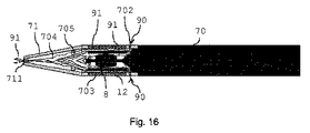
マウスピース71にはさらに、環境からの空気90が装置に入り、エアロゾル発生物品12とマウスピース壁の間、またエアロゾル発生物品12内を通過するように、マウスピースの遠位端に放射状に配置された空気吸込み口チャネル702が提供されている。それによって、空気90は、物品12のエアロゾル形成基体を加熱することによって形成されたエアロゾルを捕らえる。エアロゾル含有空気91は、さらに下流に続く。エアロゾル発生物品12の内側を通過する空気流は、気流変更要素705の通路707を通過する。エアロゾル発生物品12の外側に沿って通過する気流は、気流変更要素705の外側に沿って通過する。混合チャンバー704では、物品12の内側を通過し気流変更要素705内の通路707を通過する気流の部分が、物品12の外側を通過し、気流変更要素705の外側を通過する気流の部分と混合される。完全に混合されたエアロゾル含有気流91はその後、マウスピースの近位端にある出口開口部711を通してマウスピース71を離れるが、この気流90、91は図16に図示されている。
The
システムを使用するために準備するには、支持要素8への開いたアクセスを提供するように、ハウジング70からマウスピース71を取り外す。
To prepare the system for use, the
エアロゾル形成物品12を支持要素8の上に取り付けた後、装置の使用準備が整うように、以前に取り外したマウスピース71をハウジング70の上へ再び位置付けてもよい。
After mounting the aerosol-forming
Claims (14)
−装置ハウジングの近位端から延びる支持要素を備えた前記装置ハウジングであって、前記支持要素がエアロゾル形成基体およびサセプタ材料を含むエアロゾル発生物品を受けるように適合されているものと、
−前記支持要素に取り付けられたエアロゾル発生物品を含めて、前記支持要素を収容するような形状の内部表面を持つくぼみを備えるマウスピースと、
−使用時に前記エアロゾル発生物品の前記サセプタ材料と誘導結合された負荷ネットワークのインダクタとを備える、エアロゾル発生装置。 Aerosol generator
-The device housing with a support element extending from the proximal end of the device housing, wherein the support element is adapted to receive an aerosol-generating article containing an aerosol-forming substrate and susceptor material.
-A mouthpiece with a recess having an internal surface shaped to accommodate the support element, including an aerosol-generating article attached to the support element.
-An aerosol generator comprising the susceptor material of the aerosol generating article and an inductively coupled load network inductor in use.
−請求項9〜11のいずれか1項に記載のエアロゾル発生装置と、
−前記エアロゾル発生装置の支持要素に取り付けられたエアロゾル形成基体およびサセプタ材料を含むエアロゾル発生物品と、
−負荷ネットワークに接続された電源であって、前記負荷ネットワークが前記エアロゾル発生物品の前記サセプタ材料に誘導結合されるためのインダクタを備えるものとを備えた、エアロゾル発生システム。 Aerosol generation system
-The aerosol generator according to any one of claims 9 to 11.
-An aerosol-generating article containing an aerosol-forming substrate and susceptor material attached to a support element of the aerosol generator.
-An aerosol generation system comprising a power source connected to a load network, comprising an inductor for inductively coupling the load network to the susceptor material of the aerosol generating article.
Applications Claiming Priority (3)
| Application Number | Priority Date | Filing Date | Title |
|---|---|---|---|
| EP15190942.1 | 2015-10-22 | ||
| EP15190942 | 2015-10-22 | ||
| PCT/EP2016/075315 WO2017068099A1 (en) | 2015-10-22 | 2016-10-21 | Aerosol-generating article and method for manufacturing such aerosol-generating article; aerosol-generating device and system |
Publications (2)
| Publication Number | Publication Date |
|---|---|
| JP2018537957A JP2018537957A (en) | 2018-12-27 |
| JP6903646B2 true JP6903646B2 (en) | 2021-07-14 |
Family
ID=54360023
Family Applications (1)
| Application Number | Title | Priority Date | Filing Date |
|---|---|---|---|
| JP2018518639A Active JP6903646B2 (en) | 2015-10-22 | 2016-10-21 | Aerosol-generating articles and methods, aerosol generators and systems for manufacturing such aerosol-generating articles. |
Country Status (10)
| Country | Link |
|---|---|
| US (2) | US11632978B2 (en) |
| EP (1) | EP3364794A1 (en) |
| JP (1) | JP6903646B2 (en) |
| KR (1) | KR20180071323A (en) |
| CN (1) | CN108348004B (en) |
| CA (1) | CA3002712A1 (en) |
| IL (1) | IL258722A (en) |
| MX (1) | MX2018004463A (en) |
| RU (1) | RU2738700C2 (en) |
| WO (1) | WO2017068099A1 (en) |
Families Citing this family (91)
| Publication number | Priority date | Publication date | Assignee | Title |
|---|---|---|---|---|
| US10244793B2 (en) | 2005-07-19 | 2019-04-02 | Juul Labs, Inc. | Devices for vaporization of a substance |
| KR101953201B1 (en) | 2011-09-06 | 2019-02-28 | 브리티시 아메리칸 토바코 (인베스트먼츠) 리미티드 | Heating smokeable material |
| GB201217067D0 (en) | 2012-09-25 | 2012-11-07 | British American Tobacco Co | Heating smokable material |
| GB2507104A (en) | 2012-10-19 | 2014-04-23 | Nicoventures Holdings Ltd | Electronic inhalation device |
| GB2507102B (en) | 2012-10-19 | 2015-12-30 | Nicoventures Holdings Ltd | Electronic inhalation device |
| US10279934B2 (en) | 2013-03-15 | 2019-05-07 | Juul Labs, Inc. | Fillable vaporizer cartridge and method of filling |
| US10159282B2 (en) | 2013-12-23 | 2018-12-25 | Juul Labs, Inc. | Cartridge for use with a vaporizer device |
| KR102256889B1 (en) | 2013-12-23 | 2021-05-31 | 쥴 랩스, 인크. | Vaporization device systems and methods |
| USD842536S1 (en) | 2016-07-28 | 2019-03-05 | Juul Labs, Inc. | Vaporizer cartridge |
| USD825102S1 (en) | 2016-07-28 | 2018-08-07 | Juul Labs, Inc. | Vaporizer device with cartridge |
| US20160366947A1 (en) | 2013-12-23 | 2016-12-22 | James Monsees | Vaporizer apparatus |
| US10076139B2 (en) | 2013-12-23 | 2018-09-18 | Juul Labs, Inc. | Vaporizer apparatus |
| US10058129B2 (en) | 2013-12-23 | 2018-08-28 | Juul Labs, Inc. | Vaporization device systems and methods |
| GB201407056D0 (en) * | 2014-04-22 | 2014-06-04 | Essentra Filter Products Dev Co Pte Ltd | Smoking article |
| KR102627987B1 (en) | 2014-12-05 | 2024-01-22 | 쥴 랩스, 인크. | Calibrated dose control |
| US20170055575A1 (en) | 2015-08-31 | 2017-03-02 | British American Tobacco (Investments) Limited | Material for use with apparatus for heating smokable material |
| US11924930B2 (en) | 2015-08-31 | 2024-03-05 | Nicoventures Trading Limited | Article for use with apparatus for heating smokable material |
| US20170055584A1 (en) | 2015-08-31 | 2017-03-02 | British American Tobacco (Investments) Limited | Article for use with apparatus for heating smokable material |
| US20170119047A1 (en) | 2015-10-30 | 2017-05-04 | British American Tobacco (Investments) Limited | Article for Use with Apparatus for Heating Smokable Material |
| US20170119046A1 (en) | 2015-10-30 | 2017-05-04 | British American Tobacco (Investments) Limited | Apparatus for Heating Smokable Material |
| DE202017007467U1 (en) | 2016-02-11 | 2021-12-08 | Juul Labs, Inc. | Fillable vaporizer cartridge |
| EP3419443A4 (en) | 2016-02-11 | 2019-11-20 | Juul Labs, Inc. | Securely attaching cartridges for vaporizer devices |
| US10405582B2 (en) | 2016-03-10 | 2019-09-10 | Pax Labs, Inc. | Vaporization device with lip sensing |
| USD849996S1 (en) | 2016-06-16 | 2019-05-28 | Pax Labs, Inc. | Vaporizer cartridge |
| USD851830S1 (en) | 2016-06-23 | 2019-06-18 | Pax Labs, Inc. | Combined vaporizer tamp and pick tool |
| USD836541S1 (en) | 2016-06-23 | 2018-12-25 | Pax Labs, Inc. | Charging device |
| BR112019001990A2 (en) * | 2016-08-31 | 2019-05-07 | Philip Morris Products S.A. | inductor aerosol generator |
| US11324258B2 (en) * | 2017-08-09 | 2022-05-10 | Philip Morris Products S.A. | Aerosol-generating device with an induction heater with a conical induction coil |
| KR102551450B1 (en) | 2017-08-09 | 2023-07-06 | 필립모리스 프로덕츠 에스.에이. | Aerosol generating device with susceptor layer |
| EP3942951B1 (en) * | 2017-08-09 | 2023-10-04 | Philip Morris Products S.A. | Aerosol-generating device with detachably insertable heating compartment |
| WO2019030363A1 (en) | 2017-08-09 | 2019-02-14 | Philip Morris Products S.A. | Aerosol-generating device with flat inductor coil |
| KR102626546B1 (en) * | 2017-08-09 | 2024-01-18 | 필립모리스 프로덕츠 에스.에이. | Aerosol-generating article having a rod equipped with multiple longitudinal elongated elements of tobacco material |
| EP3664639B1 (en) | 2017-08-09 | 2021-05-26 | Philip Morris Products S.A. | Aerosol generating system with non-circular inductor coil |
| BR112020002140A2 (en) | 2017-08-09 | 2020-08-04 | Philip Morris Products S.A. | aerosol generating device that has a reduced separation induction coil |
| CN111031819B (en) | 2017-08-09 | 2023-07-18 | 菲利普莫里斯生产公司 | Aerosol generating device with removable susceptor |
| KR102368912B1 (en) | 2017-08-09 | 2022-03-03 | 필립모리스 프로덕츠 에스.에이. | Aerosol-generating device with modular induction heater |
| EP3695735B1 (en) | 2017-08-09 | 2021-04-07 | Philip Morris Products S.a.s. | Aerosol generating system with multiple inductor coils |
| JP7353266B2 (en) | 2017-08-09 | 2023-09-29 | フィリップ・モーリス・プロダクツ・ソシエテ・アノニム | Aerosol generation system with multiple susceptors |
| USD887632S1 (en) | 2017-09-14 | 2020-06-16 | Pax Labs, Inc. | Vaporizer cartridge |
| JP7206274B2 (en) * | 2017-11-30 | 2023-01-17 | フィリップ・モーリス・プロダクツ・ソシエテ・アノニム | Cartridge with inner surface susceptor material |
| EP3727055B1 (en) | 2017-12-22 | 2021-12-15 | Philip Morris Products S.A. | Aerosol-generating device with easy clean heating chamber |
| GB201722183D0 (en) | 2017-12-28 | 2018-02-14 | British American Tobacco Investments Ltd | Apparatus for heating aerosolisable material |
| GB201722177D0 (en) * | 2017-12-28 | 2018-02-14 | British American Tobacco Investments Ltd | Heating element |
| US10750787B2 (en) * | 2018-01-03 | 2020-08-25 | Cqens Technologies Inc. | Heat-not-burn device and method |
| EP3749120A1 (en) * | 2018-02-09 | 2020-12-16 | Nerudia Limited | A substitute smoking consumable |
| US11019850B2 (en) | 2018-02-26 | 2021-06-01 | Rai Strategic Holdings, Inc. | Heat conducting substrate for electrically heated aerosol delivery device |
| CN112135533B (en) * | 2018-05-21 | 2022-12-02 | Jt国际股份公司 | Aerosol-generating article, method of manufacturing the same, and aerosol-generating system |
| EA202092776A1 (en) * | 2018-05-21 | 2021-03-15 | ДжейТи ИНТЕРНЭШНЛ СА | AEROSOL GENERATING DEVICE |
| BR112020021443A2 (en) | 2018-05-25 | 2021-01-19 | Philip Morris Products S.A. | SUSCEPTOR SET FOR AEROSOL GENERATION UNDERSTANDING A SUSCEPTOR TUBE |
| US11191298B2 (en) | 2018-06-22 | 2021-12-07 | Rai Strategic Holdings, Inc. | Aerosol source member having combined susceptor and aerosol precursor material |
| KR20210024465A (en) * | 2018-06-29 | 2021-03-05 | 필립모리스 프로덕츠 에스.에이. | Cartridges for aerosol-generating systems |
| TW202011844A (en) * | 2018-07-26 | 2020-04-01 | 瑞士商Jt國際公司 | Method and apparatus for manufacturing an aerosol generating article |
| KR20210033982A (en) | 2018-07-31 | 2021-03-29 | 필립모리스 프로덕츠 에스.에이. | Aerosol-generating systems including induction-heatable cartridges and induction-heatable cartridges for aerosol-generating systems |
| GB201812489D0 (en) * | 2018-07-31 | 2018-09-12 | Nicoventures Trading Ltd | Consumable |
| GB201812492D0 (en) * | 2018-07-31 | 2018-09-12 | Nicoventures Trading Ltd | Consumable for use with apparatus for heating aerosolisable material |
| EP3829360B1 (en) * | 2018-08-02 | 2023-11-01 | Philip Morris Products S.A. | System comprising aerosol-generating device and adapter element |
| US11265974B2 (en) * | 2018-08-27 | 2022-03-01 | Rai Strategic Holdings, Inc. | Aerosol delivery device with integrated thermal conductor |
| US20210259308A1 (en) * | 2018-09-14 | 2021-08-26 | Nerudia Limited | Consumable for a smoking substitute device |
| GB201815471D0 (en) * | 2018-09-24 | 2018-11-07 | Nerudia Ltd | Aerosol delivery device |
| US20210204606A1 (en) * | 2018-09-24 | 2021-07-08 | Nerudia Limited | Aerosol delivery device |
| KR20210089683A (en) | 2018-11-05 | 2021-07-16 | 쥴 랩스, 인크. | Cartridge for carburetor device |
| BR112021010471A2 (en) * | 2018-12-17 | 2021-08-24 | Philip Morris Products S.A. | Tubular element comprising porous medium for use with an aerosol generating article |
| KR20210101213A (en) * | 2018-12-17 | 2021-08-18 | 필립모리스 프로덕츠 에스.에이. | A tubular element comprising a porous medium and a wrapper for use with an aerosol-generating article |
| GB201900627D0 (en) * | 2019-01-16 | 2019-03-06 | British American Tobacco Investments Ltd | Tobacco constituent releasing components, methods of making the components and articles comprising the components |
| KR102486921B1 (en) * | 2019-02-14 | 2023-01-10 | 주식회사 아모센스 | heater for electronic cigarette device and electronic cigarette device including the same |
| KR20210129118A (en) * | 2019-02-21 | 2021-10-27 | 제이티 인터내셔널 소시에떼 아노님 | Steam-generating articles, methods for making steam-generating articles, and steam-generating systems |
| US20220142253A1 (en) * | 2019-03-11 | 2022-05-12 | Nicoventures Trading Limited | Aerosol provision device |
| CA3132767A1 (en) * | 2019-03-11 | 2020-09-17 | Nicoventures Trading Limited | Aerosol provision device |
| US20220192249A1 (en) * | 2019-04-08 | 2022-06-23 | Philip Morris Products S.A. | Aerosol-generating article comprising an aerosol-generating film |
| CN111838739B (en) * | 2019-04-30 | 2022-06-21 | 贵州中烟工业有限责任公司 | Method for manufacturing heating non-combustion smoke body |
| RU2720904C1 (en) * | 2019-07-11 | 2020-05-14 | Общество с ограниченной ответственностью "Н-Бёрн Лтд." | Aerosol generation device |
| RU2720903C1 (en) * | 2019-07-11 | 2020-05-14 | Общество с ограниченной ответственностью "Н-Бёрн Лтд." | Aerosol generation device |
| FR3099030B1 (en) * | 2019-07-23 | 2022-11-11 | Philippe Teboul | Mouthpiece for electronic cigarette and electronic cigarette incorporating this mouthpiece |
| CN112493528B (en) * | 2019-08-26 | 2023-03-14 | 湖南中烟工业有限责任公司 | Composite functional tobacco sheet, preparation thereof and application thereof in heating non-combustible cigarettes |
| CN213045192U (en) | 2019-12-13 | 2021-04-27 | 安德烈斯·唐·塞巴斯蒂安 | Heating non-combustible smoking article |
| US11712059B2 (en) | 2020-02-24 | 2023-08-01 | Nicoventures Trading Limited | Beaded tobacco material and related method of manufacture |
| EP3942945A3 (en) * | 2020-07-08 | 2022-06-01 | Ysq International Pte. Ltd. | Tobacco unit, apparatus and method for producing the tobacco unit |
| US10932491B1 (en) * | 2020-08-06 | 2021-03-02 | Bidi Vapor, LLC | Vaporization device with nozzle cap |
| PL3984383T3 (en) * | 2020-10-15 | 2024-02-12 | Jt International Sa | A smoking article with a heated segment comprising a tobacco product |
| KR102640828B1 (en) * | 2020-10-23 | 2024-02-23 | 주식회사 케이티앤지 | Induction heating type aerosol-generating article and apparatus |
| TW202235013A (en) * | 2021-02-02 | 2022-09-16 | 瑞士商傑太日煙國際股份有限公司 | Aerosol generating device |
| GB202101466D0 (en) * | 2021-02-03 | 2021-03-17 | Nicoventures Trading Ltd | Non-combustible aerosol provision |
| JP2023517280A (en) * | 2021-02-22 | 2023-04-25 | ケーティー アンド ジー コーポレイション | Aerosol-generating article and method of making same |
| US20220312846A1 (en) * | 2021-04-02 | 2022-10-06 | R. J. Reynolds Tobacco Company | Aerosol delivery device consumable unit |
| WO2023050756A1 (en) * | 2021-09-30 | 2023-04-06 | 湖北中烟工业有限责任公司 | Induction heating tobacco section and tobacco product |
| WO2023117991A1 (en) * | 2021-12-22 | 2023-06-29 | Nicoventures Trading Limited | Aerosol generating device |
| WO2023223423A1 (en) * | 2022-05-17 | 2023-11-23 | 日本たばこ産業株式会社 | Method for manufacturing flavor rod used in non-combustible heating-type flavor inhalation article |
| WO2023223422A1 (en) * | 2022-05-17 | 2023-11-23 | 日本たばこ産業株式会社 | Production method for flavor rod for use in non-combustion heating-type flavor inhaler |
| GB202207682D0 (en) * | 2022-05-25 | 2022-07-06 | Skalene Ltd | Methods and systems for determining resonant frequencies |
| WO2024003396A1 (en) * | 2022-06-30 | 2024-01-04 | Philip Morris Products S.A. | Aerosol-generating device comprising airflow guiding element extending into heating chamber |
| JP7398591B1 (en) * | 2022-07-28 | 2023-12-14 | Future Technology株式会社 | Cartridge for smoking devices |
Family Cites Families (17)
| Publication number | Priority date | Publication date | Assignee | Title |
|---|---|---|---|---|
| US5119834A (en) * | 1985-04-15 | 1992-06-09 | R. J. Reynolds Tobacco Company | Smoking article with improved substrate |
| US5144962A (en) | 1989-12-01 | 1992-09-08 | Philip Morris Incorporated | Flavor-delivery article |
| US5396911A (en) * | 1990-08-15 | 1995-03-14 | R. J. Reynolds Tobacco Company | Substrate material for smoking articles |
| US5388594A (en) * | 1991-03-11 | 1995-02-14 | Philip Morris Incorporated | Electrical smoking system for delivering flavors and method for making same |
| US5613505A (en) * | 1992-09-11 | 1997-03-25 | Philip Morris Incorporated | Inductive heating systems for smoking articles |
| EP1972215A1 (en) * | 2007-03-20 | 2008-09-24 | Wedegree GmbH | Smoke-free cigarette substitute |
| ES2625304T3 (en) * | 2007-09-10 | 2017-07-19 | Ehc Canada, Inc. | Extrusion method and apparatus of a thermoplastic handrail |
| EP2201850A1 (en) * | 2008-12-24 | 2010-06-30 | Philip Morris Products S.A. | An article including identification information for use in an electrically heated smoking system |
| EP2338361A1 (en) | 2009-12-23 | 2011-06-29 | Philip Morris Products S.A. | An elongate heater for an electrically heated aerosol-generating system |
| US20120042885A1 (en) * | 2010-08-19 | 2012-02-23 | James Richard Stone | Segmented smoking article with monolithic substrate |
| EP2647300B1 (en) | 2010-05-06 | 2019-04-24 | R.J. Reynolds Tobacco Company | Segmented smoking article |
| HUE045286T2 (en) * | 2011-09-28 | 2019-12-30 | Philip Morris Products Sa | Permeable electric heat resistant foil for evaporating liquids out of disposable mouthpieces with evaporator nozzles |
| US20130255702A1 (en) * | 2012-03-28 | 2013-10-03 | R.J. Reynolds Tobacco Company | Smoking article incorporating a conductive substrate |
| GB201320231D0 (en) * | 2013-11-15 | 2014-01-01 | British American Tobacco Co | Aerosol generating material and devices including the same |
| CA3205347A1 (en) | 2014-02-28 | 2015-09-03 | Altria Client Services Llc | Electronic vaping device with induction heating |
| TWI666992B (en) | 2014-05-21 | 2019-08-01 | 瑞士商菲利浦莫里斯製品股份有限公司 | Aerosol-generating system and cartridge for usein the aerosol-generating system |
| TWI692274B (en) | 2014-05-21 | 2020-04-21 | 瑞士商菲利浦莫里斯製品股份有限公司 | Inductive heating device for heating an aerosol-forming substrate and method of operating an inductive heating system |
-
2016
- 2016-10-21 RU RU2018118557A patent/RU2738700C2/en active
- 2016-10-21 CN CN201680060369.9A patent/CN108348004B/en active Active
- 2016-10-21 US US15/769,440 patent/US11632978B2/en active Active
- 2016-10-21 WO PCT/EP2016/075315 patent/WO2017068099A1/en active Application Filing
- 2016-10-21 CA CA3002712A patent/CA3002712A1/en not_active Abandoned
- 2016-10-21 EP EP16785140.1A patent/EP3364794A1/en active Pending
- 2016-10-21 KR KR1020187013999A patent/KR20180071323A/en not_active Application Discontinuation
- 2016-10-21 JP JP2018518639A patent/JP6903646B2/en active Active
- 2016-10-21 MX MX2018004463A patent/MX2018004463A/en unknown
-
2018
- 2018-04-16 IL IL258722A patent/IL258722A/en unknown
-
2023
- 2023-03-06 US US18/179,218 patent/US20230200429A1/en active Pending
Also Published As
| Publication number | Publication date |
|---|---|
| IL258722A (en) | 2018-06-28 |
| JP2018537957A (en) | 2018-12-27 |
| US11632978B2 (en) | 2023-04-25 |
| MX2018004463A (en) | 2018-05-11 |
| CN108348004A (en) | 2018-07-31 |
| US20230200429A1 (en) | 2023-06-29 |
| RU2018118557A3 (en) | 2020-03-16 |
| RU2738700C2 (en) | 2020-12-15 |
| RU2018118557A (en) | 2019-11-22 |
| CN108348004B (en) | 2022-03-11 |
| KR20180071323A (en) | 2018-06-27 |
| WO2017068099A1 (en) | 2017-04-27 |
| EP3364794A1 (en) | 2018-08-29 |
| US20180279681A1 (en) | 2018-10-04 |
| CA3002712A1 (en) | 2017-04-27 |
Similar Documents
| Publication | Publication Date | Title |
|---|---|---|
| JP6903646B2 (en) | Aerosol-generating articles and methods, aerosol generators and systems for manufacturing such aerosol-generating articles. | |
| JP6876716B2 (en) | Aerosol-generating articles | |
| JP6946328B2 (en) | Hybrid aerosol generators and methods for manufacturing hybrid aerosol generators | |
| JP6876039B2 (en) | Aerosol-generating articles, aerosol-generating systems and methods for manufacturing aerosol-generating articles. | |
| JP2022522157A (en) | Induction heating aerosol forming rods and molding equipment for use in the manufacture of such rods | |
| JP2022521617A (en) | Induction heating aerosol forming rods and molding equipment for use in the manufacture of such rods | |
| JP2022522156A (en) | Induction heating aerosol forming rods and molding equipment for use in the manufacture of such rods | |
| JP2023516468A (en) | Aerosol generating system with air entry zone | |
| TW202045038A (en) | A vapour generating article, a method for manufacturing the same, and a vapour generating system | |
| JP2023517068A (en) | Aerosol-generating article with multiple air entry zones | |
| JP2023544745A (en) | Aerosol-generating articles with ventilation | |
| JP2023544746A (en) | Aerosol-generating articles with ventilation | |
| RU2816150C1 (en) | Aerosol generating system with ventilation chamber | |
| CN216393062U (en) | Aerosol-generating article | |
| JP2023517067A (en) | Aerosol-generating article with multiple air entry zones | |
| JP2023517915A (en) | Aerosol-generating article with multiple air entry zones | |
| KR20230080455A (en) | Aerosol-generating article having a non-homogenized tobacco substrate | |
| JP2023544040A (en) | Aerosol generating article with front end plug | |
| JP2023544039A (en) | Aerosol-generating articles with low withdrawal resistance and improved flavor delivery |
Legal Events
| Date | Code | Title | Description |
|---|---|---|---|
| A621 | Written request for application examination |
Free format text: JAPANESE INTERMEDIATE CODE: A621 Effective date: 20191021 |
|
| A977 | Report on retrieval |
Free format text: JAPANESE INTERMEDIATE CODE: A971007 Effective date: 20201023 |
|
| A131 | Notification of reasons for refusal |
Free format text: JAPANESE INTERMEDIATE CODE: A131 Effective date: 20201126 |
|
| A521 | Request for written amendment filed |
Free format text: JAPANESE INTERMEDIATE CODE: A523 Effective date: 20210224 |
|
| TRDD | Decision of grant or rejection written | ||
| A01 | Written decision to grant a patent or to grant a registration (utility model) |
Free format text: JAPANESE INTERMEDIATE CODE: A01 Effective date: 20210524 |
|
| A61 | First payment of annual fees (during grant procedure) |
Free format text: JAPANESE INTERMEDIATE CODE: A61 Effective date: 20210623 |
|
| R150 | Certificate of patent or registration of utility model |
Ref document number: 6903646 Country of ref document: JP Free format text: JAPANESE INTERMEDIATE CODE: R150 |