KR20210024465A - Cartridges for aerosol-generating systems - Google Patents
Cartridges for aerosol-generating systems Download PDFInfo
- Publication number
- KR20210024465A KR20210024465A KR1020207036064A KR20207036064A KR20210024465A KR 20210024465 A KR20210024465 A KR 20210024465A KR 1020207036064 A KR1020207036064 A KR 1020207036064A KR 20207036064 A KR20207036064 A KR 20207036064A KR 20210024465 A KR20210024465 A KR 20210024465A
- Authority
- KR
- South Korea
- Prior art keywords
- cartridge
- carrier material
- compartment
- aerosol
- nicotine
- Prior art date
Links
Images


Classifications
-
- A—HUMAN NECESSITIES
- A61—MEDICAL OR VETERINARY SCIENCE; HYGIENE
- A61M—DEVICES FOR INTRODUCING MEDIA INTO, OR ONTO, THE BODY; DEVICES FOR TRANSDUCING BODY MEDIA OR FOR TAKING MEDIA FROM THE BODY; DEVICES FOR PRODUCING OR ENDING SLEEP OR STUPOR
- A61M11/00—Sprayers or atomisers specially adapted for therapeutic purposes
- A61M11/04—Sprayers or atomisers specially adapted for therapeutic purposes operated by the vapour pressure of the liquid to be sprayed or atomised
- A61M11/041—Sprayers or atomisers specially adapted for therapeutic purposes operated by the vapour pressure of the liquid to be sprayed or atomised using heaters
- A61M11/042—Sprayers or atomisers specially adapted for therapeutic purposes operated by the vapour pressure of the liquid to be sprayed or atomised using heaters electrical
-
- A—HUMAN NECESSITIES
- A24—TOBACCO; CIGARS; CIGARETTES; SIMULATED SMOKING DEVICES; SMOKERS' REQUISITES
- A24B—MANUFACTURE OR PREPARATION OF TOBACCO FOR SMOKING OR CHEWING; TOBACCO; SNUFF
- A24B15/00—Chemical features or treatment of tobacco; Tobacco substitutes, e.g. in liquid form
- A24B15/10—Chemical features of tobacco products or tobacco substitutes
- A24B15/16—Chemical features of tobacco products or tobacco substitutes of tobacco substitutes
- A24B15/167—Chemical features of tobacco products or tobacco substitutes of tobacco substitutes in liquid or vaporisable form, e.g. liquid compositions for electronic cigarettes
-
- A—HUMAN NECESSITIES
- A24—TOBACCO; CIGARS; CIGARETTES; SIMULATED SMOKING DEVICES; SMOKERS' REQUISITES
- A24B—MANUFACTURE OR PREPARATION OF TOBACCO FOR SMOKING OR CHEWING; TOBACCO; SNUFF
- A24B15/00—Chemical features or treatment of tobacco; Tobacco substitutes, e.g. in liquid form
- A24B15/18—Treatment of tobacco products or tobacco substitutes
- A24B15/24—Treatment of tobacco products or tobacco substitutes by extraction; Tobacco extracts
- A24B15/241—Extraction of specific substances
- A24B15/243—Nicotine
-
- A—HUMAN NECESSITIES
- A24—TOBACCO; CIGARS; CIGARETTES; SIMULATED SMOKING DEVICES; SMOKERS' REQUISITES
- A24B—MANUFACTURE OR PREPARATION OF TOBACCO FOR SMOKING OR CHEWING; TOBACCO; SNUFF
- A24B15/00—Chemical features or treatment of tobacco; Tobacco substitutes, e.g. in liquid form
- A24B15/18—Treatment of tobacco products or tobacco substitutes
- A24B15/28—Treatment of tobacco products or tobacco substitutes by chemical substances
- A24B15/30—Treatment of tobacco products or tobacco substitutes by chemical substances by organic substances
-
- A—HUMAN NECESSITIES
- A24—TOBACCO; CIGARS; CIGARETTES; SIMULATED SMOKING DEVICES; SMOKERS' REQUISITES
- A24F—SMOKERS' REQUISITES; MATCH BOXES; SIMULATED SMOKING DEVICES
- A24F40/00—Electrically operated smoking devices; Component parts thereof; Manufacture thereof; Maintenance or testing thereof; Charging means specially adapted therefor
- A24F40/10—Devices using liquid inhalable precursors
-
- A—HUMAN NECESSITIES
- A24—TOBACCO; CIGARS; CIGARETTES; SIMULATED SMOKING DEVICES; SMOKERS' REQUISITES
- A24F—SMOKERS' REQUISITES; MATCH BOXES; SIMULATED SMOKING DEVICES
- A24F40/00—Electrically operated smoking devices; Component parts thereof; Manufacture thereof; Maintenance or testing thereof; Charging means specially adapted therefor
- A24F40/30—Devices using two or more structurally separated inhalable precursors, e.g. using two liquid precursors in two cartridges
-
- A—HUMAN NECESSITIES
- A24—TOBACCO; CIGARS; CIGARETTES; SIMULATED SMOKING DEVICES; SMOKERS' REQUISITES
- A24F—SMOKERS' REQUISITES; MATCH BOXES; SIMULATED SMOKING DEVICES
- A24F40/00—Electrically operated smoking devices; Component parts thereof; Manufacture thereof; Maintenance or testing thereof; Charging means specially adapted therefor
- A24F40/40—Constructional details, e.g. connection of cartridges and battery parts
- A24F40/42—Cartridges or containers for inhalable precursors
-
- A—HUMAN NECESSITIES
- A24—TOBACCO; CIGARS; CIGARETTES; SIMULATED SMOKING DEVICES; SMOKERS' REQUISITES
- A24F—SMOKERS' REQUISITES; MATCH BOXES; SIMULATED SMOKING DEVICES
- A24F40/00—Electrically operated smoking devices; Component parts thereof; Manufacture thereof; Maintenance or testing thereof; Charging means specially adapted therefor
- A24F40/40—Constructional details, e.g. connection of cartridges and battery parts
- A24F40/44—Wicks
-
- A—HUMAN NECESSITIES
- A24—TOBACCO; CIGARS; CIGARETTES; SIMULATED SMOKING DEVICES; SMOKERS' REQUISITES
- A24F—SMOKERS' REQUISITES; MATCH BOXES; SIMULATED SMOKING DEVICES
- A24F40/00—Electrically operated smoking devices; Component parts thereof; Manufacture thereof; Maintenance or testing thereof; Charging means specially adapted therefor
- A24F40/40—Constructional details, e.g. connection of cartridges and battery parts
- A24F40/46—Shape or structure of electric heating means
- A24F40/465—Shape or structure of electric heating means specially adapted for induction heating
-
- A—HUMAN NECESSITIES
- A24—TOBACCO; CIGARS; CIGARETTES; SIMULATED SMOKING DEVICES; SMOKERS' REQUISITES
- A24F—SMOKERS' REQUISITES; MATCH BOXES; SIMULATED SMOKING DEVICES
- A24F40/00—Electrically operated smoking devices; Component parts thereof; Manufacture thereof; Maintenance or testing thereof; Charging means specially adapted therefor
- A24F40/40—Constructional details, e.g. connection of cartridges and battery parts
- A24F40/48—Fluid transfer means, e.g. pumps
- A24F40/485—Valves; Apertures
-
- A—HUMAN NECESSITIES
- A61—MEDICAL OR VETERINARY SCIENCE; HYGIENE
- A61M—DEVICES FOR INTRODUCING MEDIA INTO, OR ONTO, THE BODY; DEVICES FOR TRANSDUCING BODY MEDIA OR FOR TAKING MEDIA FROM THE BODY; DEVICES FOR PRODUCING OR ENDING SLEEP OR STUPOR
- A61M15/00—Inhalators
- A61M15/06—Inhaling appliances shaped like cigars, cigarettes or pipes
-
- H—ELECTRICITY
- H05—ELECTRIC TECHNIQUES NOT OTHERWISE PROVIDED FOR
- H05B—ELECTRIC HEATING; ELECTRIC LIGHT SOURCES NOT OTHERWISE PROVIDED FOR; CIRCUIT ARRANGEMENTS FOR ELECTRIC LIGHT SOURCES, IN GENERAL
- H05B6/00—Heating by electric, magnetic or electromagnetic fields
- H05B6/02—Induction heating
- H05B6/10—Induction heating apparatus, other than furnaces, for specific applications
- H05B6/105—Induction heating apparatus, other than furnaces, for specific applications using a susceptor
-
- A—HUMAN NECESSITIES
- A61—MEDICAL OR VETERINARY SCIENCE; HYGIENE
- A61M—DEVICES FOR INTRODUCING MEDIA INTO, OR ONTO, THE BODY; DEVICES FOR TRANSDUCING BODY MEDIA OR FOR TAKING MEDIA FROM THE BODY; DEVICES FOR PRODUCING OR ENDING SLEEP OR STUPOR
- A61M15/00—Inhalators
- A61M15/0001—Details of inhalators; Constructional features thereof
- A61M15/0003—Details of inhalators; Constructional features thereof with means for dispensing more than one drug
-
- A—HUMAN NECESSITIES
- A61—MEDICAL OR VETERINARY SCIENCE; HYGIENE
- A61M—DEVICES FOR INTRODUCING MEDIA INTO, OR ONTO, THE BODY; DEVICES FOR TRANSDUCING BODY MEDIA OR FOR TAKING MEDIA FROM THE BODY; DEVICES FOR PRODUCING OR ENDING SLEEP OR STUPOR
- A61M15/00—Inhalators
- A61M15/0001—Details of inhalators; Constructional features thereof
- A61M15/0021—Mouthpieces therefor
-
- A—HUMAN NECESSITIES
- A61—MEDICAL OR VETERINARY SCIENCE; HYGIENE
- A61M—DEVICES FOR INTRODUCING MEDIA INTO, OR ONTO, THE BODY; DEVICES FOR TRANSDUCING BODY MEDIA OR FOR TAKING MEDIA FROM THE BODY; DEVICES FOR PRODUCING OR ENDING SLEEP OR STUPOR
- A61M2205/00—General characteristics of the apparatus
- A61M2205/02—General characteristics of the apparatus characterised by a particular materials
- A61M2205/0233—Conductive materials, e.g. antistatic coatings for spark prevention
-
- A—HUMAN NECESSITIES
- A61—MEDICAL OR VETERINARY SCIENCE; HYGIENE
- A61M—DEVICES FOR INTRODUCING MEDIA INTO, OR ONTO, THE BODY; DEVICES FOR TRANSDUCING BODY MEDIA OR FOR TAKING MEDIA FROM THE BODY; DEVICES FOR PRODUCING OR ENDING SLEEP OR STUPOR
- A61M2205/00—General characteristics of the apparatus
- A61M2205/02—General characteristics of the apparatus characterised by a particular materials
- A61M2205/0238—General characteristics of the apparatus characterised by a particular materials the material being a coating or protective layer
-
- A—HUMAN NECESSITIES
- A61—MEDICAL OR VETERINARY SCIENCE; HYGIENE
- A61M—DEVICES FOR INTRODUCING MEDIA INTO, OR ONTO, THE BODY; DEVICES FOR TRANSDUCING BODY MEDIA OR FOR TAKING MEDIA FROM THE BODY; DEVICES FOR PRODUCING OR ENDING SLEEP OR STUPOR
- A61M2205/00—General characteristics of the apparatus
- A61M2205/50—General characteristics of the apparatus with microprocessors or computers
- A61M2205/502—User interfaces, e.g. screens or keyboards
- A61M2205/505—Touch-screens; Virtual keyboard or keypads; Virtual buttons; Soft keys; Mouse touches
-
- A—HUMAN NECESSITIES
- A61—MEDICAL OR VETERINARY SCIENCE; HYGIENE
- A61M—DEVICES FOR INTRODUCING MEDIA INTO, OR ONTO, THE BODY; DEVICES FOR TRANSDUCING BODY MEDIA OR FOR TAKING MEDIA FROM THE BODY; DEVICES FOR PRODUCING OR ENDING SLEEP OR STUPOR
- A61M2205/00—General characteristics of the apparatus
- A61M2205/82—Internal energy supply devices
- A61M2205/8206—Internal energy supply devices battery-operated
Abstract
니코틴 염 입자를 포함하는 에어로졸의 발생을 위해 에어로졸 발생 시스템(10)에 사용하기 위한 카트리지(100)가 제공된다. 카트리지(100)는 니코틴으로 함침된 제1 캐리어 재료(211)를 포함하는 니코틴 공급원(210)을 포함하는 제1 구획부(110)를 포함하며, 제1 구획부(110)는 제1 공기 유입구(132) 및 제1 공기 배출구(133)를 갖는다. 제1 구획부(110)는 제1 공기 유입구(132)와 제1 공기 배출구(133) 사이에서 제1 캐리어 재료(211)의 제1 표면(213)에 걸쳐 연장되는 제1 기류 경로(217)를 정의한다. 카트리지(100)는 또한 산으로 함침된 제2 캐리어 재료(221)를 포함하는 산 공급원(220)을 포함하는 제2 구획부(120)를 포함하며, 제2 구획부(220)는 제2 공기 유입구(134) 및 제2 공기 배출구(135)를 갖는다. 제2 구획부(220)는 제2 공기 유입구(134)와 제2 공기 배출구(135) 사이에서 제2 캐리어 재료(221)의 제1 표면(223)에 걸쳐 연장되는 제2 기류 경로(227)를 정의한다. 제1 구획부(110) 및 제2 구획부(220)는 카트리지(100) 내에 병렬로 배열된다. 제1 캐리어 재료(211) 및 제2 캐리어 재료(221) 중 적어도 하나의 두께는 제1 기류 경로(217) 또는 제2 기류 경로(227)를 각각 따르는 방향으로 각각 변화된다.A cartridge 100 is provided for use in an aerosol-generating system 10 for the generation of an aerosol comprising nicotine salt particles. The cartridge 100 comprises a first compartment 110 comprising a nicotine source 210 comprising a first carrier material 211 impregnated with nicotine, the first compartment 110 being a first air inlet (132) and a first air outlet (133). The first compartment 110 is a first air flow path 217 extending over the first surface 213 of the first carrier material 211 between the first air inlet 132 and the first air outlet 133 Is defined. The cartridge 100 also includes a second compartment 120 comprising an acid source 220 comprising a second carrier material 221 impregnated with acid, and the second compartment 220 It has an inlet port 134 and a second air outlet port 135. The second compartment 220 is a second airflow path 227 extending over the first surface 223 of the second carrier material 221 between the second air inlet 134 and the second air outlet 135 Is defined. The first partition 110 and the second partition 220 are arranged in parallel in the cartridge 100. The thickness of at least one of the first carrier material 211 and the second carrier material 221 is respectively changed in a direction along the first airflow path 217 or the second airflow path 227, respectively.
Description
본 발명은 에어로졸 발생 시스템에 사용하기 위한 카트리지에 관한 것이며, 카트리지는 가변 두께를 갖는 적어도 하나의 캐리어 재료를 포함한다. 본 발명은 또한 카트리지를 포함하는 에어로졸 발생 시스템에 관한 것이다.The present invention relates to a cartridge for use in an aerosol-generating system, the cartridge comprising at least one carrier material having a variable thickness. The invention also relates to an aerosol-generating system comprising a cartridge.
일부 핸드헬드 에어로졸 발생 시스템에서, 니코틴 공급원 및 휘발성 전달 강화 화합물, 예를 들어 산 공급원을 가열하기 위해 전기 히터가 사용된다. 이러한 에어로졸 발생 장치에서, 기화된 니코틴 및 산은 기상(gas phase)으로 서로 반응하여, 사용자가 흡입하는 니코틴 염 입자의 에어로졸을 형성한다.In some handheld aerosol-generating systems, electric heaters are used to heat nicotine sources and volatile delivery enhancing compounds, such as acid sources. In such an aerosol-generating device, vaporized nicotine and acid react with each other in a gas phase, forming an aerosol of nicotine salt particles inhaled by the user.
이러한 시스템에서 니코틴 및 산의 증기 농도 사이의 차이는 불리하게도 사용자에게 미반응 니코틴 증기 또는 미반응 산 증기와 같은 과잉 반응물의 전달 또는 바람직하지 않은 반응 화학량론을 초래할 수 있다. 따라서, 산 증기 및 니코틴 증기의 농도를 제어하고 밸런싱하여 니코틴 공급원 및 산 공급원의 시차 가열을 통해 효율적인 반응 화학량론을 야기하는 것이 공지되어 있다.The difference between the vapor concentrations of nicotine and acid in such systems can unfavorably lead to the delivery of excess reactants such as unreacted nicotine vapor or unreacted acid vapor to the user or undesirable reaction stoichiometry. Accordingly, it is known to control and balance the concentration of acid vapor and nicotine vapor to result in an efficient reaction stoichiometry through differential heating of the nicotine source and the acid source.
예를 들어, WO 2014/140230 A1은 제1 구획부를 제2 구획부보다 낮은 온도로 가열함으로써 산 공급원을 포함하는 제1 구획부 및 니코틴 공급원을 포함하는 제2 구획부를 포함하는 에어로졸 발생 물품을 포함하는 에어로졸 발생 시스템에 의해 니코틴 염 입자의 에어로졸의 형성을 제어하는 것을 개시한다.For example, WO 2014/140230 A1 includes an aerosol-generating article comprising a first compartment comprising an acid source and a second compartment comprising a nicotine source by heating the first compartment to a lower temperature than the second compartment. And controlling the formation of aerosols of nicotine salt particles by means of an aerosol-generating system.
또한 산 증기 및 니코틴 증기의 농도를 제어하고 밸런싱하여 효율적인 반응 화학량론을 니코틴 공급원 및 산 공급원을 포함하는 구획부를 통한 체적 기류의 변형을 통해 야기하는 것이 공지되어 있다. 예를 들어, WO 2017/108987 A1은 적절한 반응 화학량론을 달성하는 데 필요한 니코틴 및 락트산의 비율이 카트리지의 제2 구획부를 통한 체적 기류에 대한 카트리지의 제1 구획부를 통한 체적 기류의 변형을 통해 제어되고 밸런싱될 수 있는 것을 교시한다. WO 2017/108987 A1은 제2 구획부를 통한 체적 기류에 대한 제1 구획부를 통한 체적 기류의 비율이 카트리지의 제2 구획부의 제2 공기 유입구의 유동 면적에 대한 카트리지의 제1 구획부의 제1 공기 유입구의 유동 면적의 변형을 통해 제어될 수 있는 것을 교시한다.It is also known to control and balance the concentrations of acid vapors and nicotine vapors resulting in an efficient reaction stoichiometry through modification of the volumetric airflow through the compartment containing the nicotine source and the acid source. For example, WO 2017/108987 A1 states that the ratio of nicotine and lactic acid required to achieve an appropriate reaction stoichiometry is controlled through the modification of the volumetric airflow through the first compartment of the cartridge to the volumetric airflow through the second compartment of the cartridge. It teaches what can be done and balanced. WO 2017/108987 A1 is that the ratio of the volumetric airflow through the first compartment to the volumetric airflow through the second compartment is the first air inlet of the cartridge to the flow area of the second air inlet of the second compartment of the cartridge It teaches that it can be controlled through the transformation of the flow area of
그러나, 본 발명자들은 다른 인자가 효율적인 반응 화학량론에서 떨어져서 니코틴 증기 및 산 증기의 상대적인 양을 유도하는 역할을 할 수 있는 것을 인식하였다. 예를 들어, 공지된 시스템은 통상적으로 니코틴으로 함침된 제1 평면형 캐리어 재료를 포함하는 니코틴 공급원을 포함하는 제1 구획부 및 산으로 함침된 제2 평면형 캐리어 재료를 포함하는 산 공급원을 포함하는 제2 구획부를 포함한다. 본 발명자들은, 예를 들어 제조 공차로 인해 발생할 수 있는 제1 및 제2 캐리어 재료의 치수의 균일한 변형이 제1 및 제2 구획부의 흡인 저항에 영향을 미칠 수 있으며, 이는 제1 및 제2 구획부를 통한 체적 기류를 바람직하지 않게 변경시킬 수 있는 것을 발견하였다. 제조 공차로 인해 제1 및 제2 구획부를 통한 일관되지 않은 체적 기류는 니코틴 증기 대 산 증기의 비율에 악영향을 미칠 수 있다. 제조 공차로 인해 제1 및 제2 구획부를 통한 일관되지 않은 체적 기류는 복수의 카트리지의 사용에 걸쳐 일관되지 않은 사용자 경험을 초래할 수 있다.However, the inventors have recognized that other factors may play a role in deriving the relative amounts of nicotine vapor and acid vapor away from the efficient reaction stoichiometry. For example, known systems typically include a first compartment comprising a nicotine source comprising a first planar carrier material impregnated with nicotine and an acid source comprising a second planar carrier material impregnated with an acid. Includes 2 divisions. The inventors believe that uniform deformation of the dimensions of the first and second carrier materials, which may occur due for example due to manufacturing tolerances, may affect the suction resistance of the first and second compartments, which It has been found that the volumetric airflow through the compartment can be undesirably altered. Due to manufacturing tolerances, inconsistent volumetric airflow through the first and second compartments can adversely affect the ratio of nicotine vapor to acid vapor. Inconsistent volumetric airflow through the first and second compartments due to manufacturing tolerances can lead to inconsistent user experiences across the use of multiple cartridges.
니코틴 염 입자를 포함하는 에어로졸의 발생을 위해 에어로졸 발생 시스템용 카트리지를 제공하는 것이 바람직할 것이며, 카트리지는 캐리어 재료의 치수의 제조 공차의 효과를 감소시키거나 완화한다.It would be desirable to provide a cartridge for an aerosol-generating system for the generation of an aerosol comprising nicotine salt particles, the cartridge reducing or mitigating the effect of manufacturing tolerances in the dimensions of the carrier material.
본 발명의 제1 양태에 따르면, 니코틴 염 입자를 포함하는 에어로졸의 발생을 위해 에어로졸 발생 시스템에 사용하기 위한 카트리지가 제공된다. 카트리지는 니코틴으로 함침된 제1 캐리어 재료를 포함하는 니코틴 공급원을 포함하는 제1 구획부를 포함하며, 제1 구획부는 제1 공기 유입구 및 제1 공기 배출구를 갖는다. 제1 구획부는 제1 공기 유입구와 제1 공기 배출구 사이에서 제1 캐리어 재료의 제1 표면에 걸쳐 연장되는 제1 기류 경로를 정의한다. 카트리지는 또한 산으로 함침된 제2 캐리어 재료를 포함하는 산 공급원을 포함하는 제2 구획부를 포함하며, 제2 구획부는 제2 공기 유입구 및 제2 공기 배출구를 갖는다. 제2 구획부는 제2 공기 유입구와 제2 공기 배출구 사이에서 제2 캐리어 재료의 제1 표면에 걸쳐 연장되는 제2 기류 경로를 정의한다. 제1 구획부 및 제2 구획부는 카트리지 내부에 병렬로 배열된다. 제1 캐리어 재료 및 제2 캐리어 재료 중 적어도 하나의 두께는 제1 기류 경로 또는 제2 기류 경로를 각각 따르는 방향으로 변화된다.According to a first aspect of the present invention, there is provided a cartridge for use in an aerosol-generating system for the generation of an aerosol comprising nicotine salt particles. The cartridge includes a first compartment comprising a nicotine source comprising a first carrier material impregnated with nicotine, the first compartment having a first air inlet and a first air outlet. The first partition defines a first airflow path extending over the first surface of the first carrier material between the first air inlet and the first air outlet. The cartridge also includes a second compartment comprising an acid source comprising a second carrier material impregnated with acid, the second compartment having a second air inlet and a second air outlet. The second partition defines a second airflow path extending over the first surface of the second carrier material between the second air inlet and the second air outlet. The first partition and the second partition are arranged in parallel inside the cartridge. The thickness of at least one of the first carrier material and the second carrier material is varied in a direction along the first airflow path or the second airflow path, respectively.
본 발명을 참조하여 본원에서 사용되는 바와 같이, 용어 "공기 유입구"는, 카트리지의 구성요소 또는 구성요소의 일부 내로 공기가 흡인될 수 있는 하나 이상의 애퍼처를 설명하는 데 사용된다.As used herein with reference to the present invention, the term “air inlet” is used to describe one or more apertures through which air may be drawn into a component or portion of a cartridge.
본 발명을 참조하여 본원에서 사용되는 바와 같이, 용어 "공기 배출구"는, 카트리지의 구성요소 또는 구성요소의 일부의 외부로 공기가 흡인될 수 있는 하나 이상의 애퍼처를 설명하는 데 사용된다.As used herein with reference to the present invention, the term “air outlet” is used to describe one or more apertures through which air may be drawn out of a component or portion of a cartridge.
본 발명을 참조하여 본원에서 사용되는 바와 같이, "병렬"은 사용 시 카트리지를 통해 흡인되는 제1 공기 스트림이 제1 공기 유입구를 통해 제1 구획부 내로 통과하고, 제1 구획부를 통해 하류로 통과하고 제1 공기 배출구를 통해 제1 구획부의 외부로 통과하고 카트리지를 통해 흡인되는 제2 공기 스트림이 제2 공기 유입구를 통해 제2 구획부 내로 통과하고, 제2 구획부를 통해 하류로 통과하고 제2 공기 배출구를 통해 제2 구획부의 외부로 통과하도록 제1 구획부 및 제2 구획부가 카트리지 내에 배열되는 것을 의미한다. 니코틴 증기는 제1 구획부의 니코틴 공급원으로부터 카트리지를 통해 흡인되는 제1 공기 스트림 내로 방출되고, 산 증기는 제2 구획부의 산 공급원으로부터 카트리지를 통해 흡인되는 제2 공기 스트림 내로 방출된다. 제1 공기 스트림의 니코틴 증기는 기상 상태에서 제2 공기 스트림의 산 증기와 반응하여 니코틴 염 입자의 에어로졸을 형성하게 된다.As used herein with reference to the present invention, "parallel" means that a first air stream drawn through the cartridge when in use passes into the first compartment through the first air inlet, and passes downstream through the first compartment. And a second air stream that passes through the first air outlet to the outside of the first compartment and sucked through the cartridge passes through the second air inlet into the second compartment, passes downstream through the second compartment, and a second air stream. It means that the first compartment and the second compartment are arranged in the cartridge to pass through the air outlet to the outside of the second compartment. Nicotine vapor is discharged from a nicotine source in the first compartment into a first air stream that is drawn through the cartridge, and acid vapor is released from an acid source in the second compartment into a second air stream that is drawn through the cartridge. The nicotine vapor of the first air stream reacts with the acid vapor of the second air stream in the gas phase to form an aerosol of nicotine salt particles.
본 발명에 따른 카트리지는 제1 및 제2 캐리어 재료를 포함하며, 제1 및 제2 캐리어 재료 중 적어도 하나의 두께는 제1 기류 경로 또는 제2 기류 경로를 각각 따르는 방향으로 변화된다.The cartridge according to the invention comprises a first and a second carrier material, wherein the thickness of at least one of the first and second carrier materials is varied in a direction along the first airflow path or the second airflow path respectively.
유리하게는, 본 발명자들은 캐리어 재료의 표면에 걸친 기류 경로를 따라 가변 두께를 갖는 캐리어 재료를 사용하는 것이 균일한 평면 형상을 갖는 캐리어 재료를 포함하는 공지된 시스템과 비교할 때 캐리어 재료의 두께의 제조 공차의 효과를 감소시키거나 완화하는 것을 인식하였다. 즉, 제조 공차로 인한 캐리어 재료의 두께의 균일한 변화는 캐리어 재료가 캐리어 재료의 표면에 걸친 기류 경로의 길이를 따라 가변 두께로 형성될 때 캐리어 재료를 포함하는 구획부를 통한 체적 기류에 대한 감소되거나 완화된 효과를 갖는다.Advantageously, the present inventors find that using a carrier material having a variable thickness along the airflow path across the surface of the carrier material is the production of the thickness of the carrier material when compared to known systems comprising a carrier material having a uniform planar shape. It was recognized to reduce or mitigate the effect of tolerance. That is, a uniform change in the thickness of the carrier material due to manufacturing tolerances is reduced to the volumetric airflow through the compartment containing the carrier material when the carrier material is formed to a variable thickness along the length of the airflow path across the surface of the carrier material. It has a moderate effect.
유리하게는, 본 발명자들은 캐리어 재료의 표면에 걸친 기류 경로를 따라 가변 두께를 갖는 캐리어 재료를 사용하는 것이 캐리어 재료를 포함하는 구획부를 통한 흡인 저항의 보다 정밀한 제어를 용이하게 하는 것을 인식하였다. 유리하게는, 제1 및 제2 구획부 중 적어도 하나를 통한 흡인 저항의 보다 정밀한 제어는 니코틴 증기 및 산 증기의 비율의 제어를 용이하게 하며, 이는 효율적인 반응 화학량론을 용이하게 한다.Advantageously, the inventors have recognized that the use of a carrier material having a variable thickness along the airflow path across the surface of the carrier material facilitates a more precise control of the suction resistance through the compartment containing the carrier material. Advantageously, a more precise control of the suction resistance through at least one of the first and second compartments facilitates control of the ratio of nicotine vapor and acid vapor, which facilitates efficient reaction stoichiometry.
바람직하게는, 제1 캐리어 재료의 두께는 제1 기류 경로를 따르는 방향으로 변화되고, 제2 캐리어 재료의 두께는 제2 기류 경로를 따르는 방향으로 변화된다. 유리하게는, 각각의 기류 경로의 길이를 따라 가변 두께를 갖는 제1 및 제2 캐리어 재료 각각을 제공하는 것은 제1 및 제2 구획부 둘 모두를 통한 체적 기류 상의 캐리어 재료의 두께에서의 제조 공차의 효과를 감소시키거나 완화할 수 있다.Preferably, the thickness of the first carrier material is changed in a direction along the first airflow path, and the thickness of the second carrier material is changed in a direction along the second airflow path. Advantageously, providing each of the first and second carrier materials having a variable thickness along the length of the respective airflow path is a manufacturing tolerance in the thickness of the carrier material on the volumetric airflow through both the first and second compartments. Can reduce or mitigate the effect of
제1 캐리어 재료가 제1 기류 경로의 길이를 따라 가변 두께를 갖는 구현예에서, 제1 캐리어 재료는 테이퍼진 형상을 가질 수 있다.In embodiments where the first carrier material has a variable thickness along the length of the first airflow path, the first carrier material may have a tapered shape.
제1 캐리어 재료가 제1 기류 경로의 길이를 따라 가변 두께를 갖는 구현예에서, 바람직하게는 제1 캐리어 재료의 제1 표면의 적어도 일부는 비평면 형상을 갖는다. 유리하게는, 제1 캐리어 재료의 비평면 제1 표면은 제1 캐리어 재료의 두께에서 제조 공차의 효과의 감소 또는 완화를 최적화할 수 있다. 제1 캐리어 재료의 제1 표면의 적어도 일부는 볼록한 형상, 오목한 형상, 파형 형상, 다면적 형상, 하나 이상의 함몰부, 및 하나 이상의 돌출부 중 적어도 하나를 가질 수 있다. 제1 캐리어 재료의 제1 표면은 대칭 형상을 가질 수 있다. 제1 캐리어 재료의 제1 표면은 비대칭 형상을 가질 수 있다.In embodiments in which the first carrier material has a variable thickness along the length of the first airflow path, preferably at least a portion of the first surface of the first carrier material has a non-planar shape. Advantageously, the non-planar first surface of the first carrier material can optimize the reduction or relaxation of the effect of manufacturing tolerances in the thickness of the first carrier material. At least a portion of the first surface of the first carrier material may have at least one of a convex shape, a concave shape, a corrugated shape, a multi-faceted shape, one or more depressions, and one or more protrusions. The first surface of the first carrier material can have a symmetrical shape. The first surface of the first carrier material may have an asymmetric shape.
제1 캐리어 재료의 제1 표면의 적어도 일부가 하나 이상의 돌출부를 갖는 구현예에서, 하나 이상의 돌출부는 임의의 적합한 크기 및 형상을 가질 수 있다.In embodiments in which at least a portion of the first surface of the first carrier material has one or more protrusions, the one or more protrusions may have any suitable size and shape.
하나 이상의 돌출부는 각각 직육면체 형상을 가질 수 있다. 하나 이상의 돌출부는 각각 돔형 형상을 가질 수 있다. 하나 이상의 돌출부는 각각 반구형 형상을 가질 수 있다. 하나 이상의 돌출부는 제1 캐리어 재료의 제1 표면의 적어도 일부에 걸쳐 그리드 또는 어레이로 배열될 수 있다.Each of the one or more protrusions may have a rectangular parallelepiped shape. Each of the one or more protrusions may have a dome shape. Each of the one or more protrusions may have a hemispherical shape. The one or more protrusions may be arranged in a grid or array over at least a portion of the first surface of the first carrier material.
하나 이상의 돌출부는 하나 이상의 세장형 융기부를 포함할 수 있다. 바람직하게는, 하나 이상의 세장형 융기부는 제1 기류 경로에 대해 수직으로 연장된다.The one or more protrusions may include one or more elongate protrusions. Preferably, the one or more elongated ridges extend perpendicular to the first airflow path.
제1 캐리어 재료의 제1 표면의 적어도 일부가 하나 이상의 함몰부를 갖는 구현예에서, 하나 이상의 함몰부는 임의의 적합한 크기 및 형상을 가질 수 있다.In embodiments in which at least a portion of the first surface of the first carrier material has one or more depressions, the one or more depressions can have any suitable size and shape.
하나 이상의 함몰부는 각각 직육면체 형상을 가질 수 있다. 하나 이상의 함몰부는 각각 볼(bowl) 형상을 가질 수 있다. 하나 이상의 함몰부는 각각 반구형 형상을 가질 수 있다. 하나 이상의 함몰부는 제1 캐리어 재료의 제1 표면의 적어도 일부에 걸쳐 그리드 또는 어레이로 배열될 수 있다.Each of the one or more depressions may have a rectangular parallelepiped shape. Each of the one or more depressions may have a bowl shape. Each of the one or more depressions may have a hemispherical shape. The one or more depressions may be arranged in a grid or array over at least a portion of the first surface of the first carrier material.
하나 이상의 함몰부는 하나 이상의 세장형 홈을 포함할 수 있다. 바람직하게는, 하나 이상의 세장형 홈은 제1 기류 경로에 대해 수직으로 연장된다.The one or more depressions may include one or more elongated grooves. Preferably, the at least one elongate groove extends perpendicular to the first airflow path.
제1 캐리어 재료의 제1 표면의 적어도 일부가 다면적 형상을 갖는 구현예에서, 다면적 형상은 경사 부분 및 감소 부분 중 적어도 하나를 포함할 수 있다. 본원에서 사용되는 바와 같이, "경사 부분"은 제1 표면에 걸친 기류 경로를 따라 기류의 방향으로 캐리어 재료의 두께의 선형 증가를 나타내는 캐리어 재료의 일부이다. 본원에서 사용되는 바와 같이, "감소 부분"은 제1 표면에 걸친 기류 경로를 따라 기류의 방향으로 캐리어 재료의 두께의 선형 감소를 나타내는 캐리어 재료의 일부이다.In embodiments in which at least a portion of the first surface of the first carrier material has a multi-faceted shape, the multi-faceted shape may comprise at least one of an inclined portion and a reduced portion. As used herein, a "sloping portion" is a portion of a carrier material that exhibits a linear increase in the thickness of the carrier material in the direction of the airflow along the airflow path over the first surface. As used herein, a “reduced portion” is a portion of a carrier material that exhibits a linear decrease in the thickness of the carrier material in the direction of the airflow along the airflow path over the first surface.
제2 캐리어 재료가 제2 기류 경로의 길이를 따라 가변 두께를 갖는 구현예에서, 제2 캐리어 재료는 테이퍼진 형상을 가질 수 있다.In embodiments where the second carrier material has a variable thickness along the length of the second airflow path, the second carrier material may have a tapered shape.
제2 캐리어 재료가 제2 기류 경로의 길이를 따라 가변 두께를 갖는 구현예에서, 바람직하게는 제2 캐리어 재료의 제1 표면의 적어도 일부는 비평면 형상을 갖는다. 유리하게는, 제2 캐리어 재료의 비평면 제1 표면은 제2 캐리어 재료의 두께에서 제조 공차의 효과의 감소 또는 완화를 최적화할 수 있다. 제2 캐리어 재료의 제1 표면의 적어도 일부는 볼록한 형상, 오목한 형상, 파형 형상, 다면적 형상, 하나 이상의 함몰부, 및 하나 이상의 돌출부 중 적어도 하나를 가질 수 있다. 제2 캐리어 재료의 제1 표면은 대칭 형상을 가질 수 있다. 제2 캐리어 재료의 제1 표면은 비대칭 형상을 가질 수 있다.In embodiments in which the second carrier material has a variable thickness along the length of the second airflow path, preferably at least a portion of the first surface of the second carrier material has a non-planar shape. Advantageously, the non-planar first surface of the second carrier material can optimize the reduction or relaxation of the effect of manufacturing tolerances in the thickness of the second carrier material. At least a portion of the first surface of the second carrier material may have at least one of a convex shape, a concave shape, a corrugated shape, a multi-faceted shape, one or more depressions, and one or more protrusions. The first surface of the second carrier material can have a symmetrical shape. The first surface of the second carrier material may have an asymmetric shape.
제2 캐리어 재료의 제1 표면의 적어도 일부가 하나 이상의 돌출부를 갖는 구현예에서, 하나 이상의 돌출부는 임의의 적합한 크기 및 형상을 가질 수 있다.In embodiments in which at least a portion of the first surface of the second carrier material has one or more protrusions, the one or more protrusions may have any suitable size and shape.
하나 이상의 돌출부는 각각 직육면체 형상을 가질 수 있다. 하나 이상의 돌출부는 각각 돔형 형상을 가질 수 있다. 하나 이상의 돌출부는 각각 반구형 형상을 가질 수 있다. 하나 이상의 돌출부는 제2 캐리어 재료의 제1 표면의 적어도 일부에 걸쳐 그리드 또는 어레이로 배열될 수 있다.Each of the one or more protrusions may have a rectangular parallelepiped shape. Each of the one or more protrusions may have a dome shape. Each of the one or more protrusions may have a hemispherical shape. The one or more protrusions may be arranged in a grid or array over at least a portion of the first surface of the second carrier material.
하나 이상의 돌출부는 하나 이상의 세장형 융기부를 포함할 수 있다. 바람직하게는, 하나 이상의 세장형 융기부는 제2 기류 경로에 대해 수직으로 연장된다.The one or more protrusions may include one or more elongate protrusions. Preferably, the one or more elongate ridges extend perpendicular to the second airflow path.
제2 캐리어 재료의 제1 표면의 적어도 일부가 하나 이상의 함몰부를 갖는 구현예에서, 하나 이상의 함몰부는 임의의 적합한 크기 및 형상을 가질 수 있다.In embodiments in which at least a portion of the first surface of the second carrier material has one or more depressions, the one or more depressions may have any suitable size and shape.
하나 이상의 함몰부는 각각 직육면체 형상을 가질 수 있다. 하나 이상의 함몰부는 각각 볼 형상을 가질 수 있다. 하나 이상의 함몰부는 각각 반구형 형상을 가질 수 있다. 하나 이상의 함몰부는 제2 캐리어 재료의 제1 표면의 적어도 일부에 걸쳐 그리드 또는 어레이로 배열될 수 있다.Each of the one or more depressions may have a rectangular parallelepiped shape. Each of the one or more depressions may have a ball shape. Each of the one or more depressions may have a hemispherical shape. The one or more depressions may be arranged in a grid or array over at least a portion of the first surface of the second carrier material.
하나 이상의 함몰부는 하나 이상의 세장형 홈을 포함할 수 있다. 바람직하게는, 하나 이상의 세장형 홈은 제2 기류 경로에 대해 수직으로 연장된다.The one or more depressions may include one or more elongated grooves. Preferably, the one or more elongated grooves extend perpendicular to the second airflow path.
제1 캐리어 재료의 제1 표면의 적어도 일부가 다면적 형상을 갖는 구현예에서, 다면적 형상은 경사 부분 및 감소 부분 중 적어도 하나를 포함할 수 있다.In embodiments in which at least a portion of the first surface of the first carrier material has a multi-faceted shape, the multi-faceted shape may comprise at least one of an inclined portion and a reduced portion.
바람직하게는, 카트리지는 제1 구획부 및 제2 구획부를 정의하는 카트리지 하우징을 포함한다. 바람직하게는, 제1 캐리어 재료는 제1 캐리어 재료의 제2 표면에서 카트리지 하우징에 고정되고, 제2 캐리어 재료는 제2 캐리어 재료의 제2 표면에서 카트리지 하우징에 고정된다.Preferably, the cartridge comprises a cartridge housing defining a first compartment and a second compartment. Preferably, the first carrier material is secured to the cartridge housing at the second surface of the first carrier material, and the second carrier material is secured to the cartridge housing at the second surface of the second carrier material.
바람직하게는, 제1 캐리어 재료의 제1 표면은 제1 캐리어 재료의 제2 표면과 대향한다. 즉, 바람직하게는 제1 및 제2 표면은 제1 캐리어 재료의 대향 측부를 정의한다. 제1 캐리어 재료의 두께는 제1 캐리어 재료의 제1 및 제2 표면 사이에서 연장된다.Preferably, the first surface of the first carrier material faces the second surface of the first carrier material. That is, preferably the first and second surfaces define opposite sides of the first carrier material. The thickness of the first carrier material extends between the first and second surfaces of the first carrier material.
바람직하게는, 제2 캐리어 재료의 제1 표면은 제2 캐리어 재료의 제2 표면과 대향한다. 즉, 바람직하게는 제1 및 제2 표면은 제2 캐리어 재료의 대향 측부를 정의한다. 제2 캐리어 재료의 두께는 제2 캐리어 재료의 제1 및 제2 표면 사이에서 연장된다.Preferably, the first surface of the second carrier material faces the second surface of the second carrier material. That is, preferably the first and second surfaces define opposite sides of the second carrier material. The thickness of the second carrier material extends between the first and second surfaces of the second carrier material.
카트리지의 제1 구획부의 제1 공기 유입구 및 카트리지의 제2 구획부의 제2 공기 유입구는 하나 이상의 애퍼처를 각각 포함할 수 있다. 예를 들어, 카트리지의 제1 구획부의 제1 공기 유입구와 카트리지의 제2 구획부의 제2 공기 유입구는 각각 1개, 2개, 3개, 4개, 5개, 6개, 또는 7개의 애퍼처를 포함할 수 있다.The first air inlet of the first compartment of the cartridge and the second air inlet of the second compartment of the cartridge may each include one or more apertures. For example, the first air inlet of the first compartment of the cartridge and the second air inlet of the second compartment of the cartridge are 1, 2, 3, 4, 5, 6, or 7 apertures, respectively. It may include.
카트리지의 제1 구획부의 제1 공기 유입구와 카트리지의 제2 구획부의 제2 공기 유입구는, 동일하거나 상이한 수의 애퍼처를 포함할 수 있다.The first air inlet of the first compartment of the cartridge and the second air inlet of the second compartment of the cartridge may comprise the same or a different number of apertures.
본 발명에 관하여 본원에서 사용되는 바와 같이, 용어 "니코틴"은 니코틴, 니코틴 염기, 또는 니코틴 염을 설명하는 데 사용된다. 제1 캐리어 재료가 니코틴 염기 또는 니코틴 염으로 함침된 구현예에서, 본원에서 나열되는 니코틴의 양은 각각 니코틴 염기의 양 또는 이온화된 니코틴의 양이다.As used herein in connection with the present invention, the term “nicotine” is used to describe nicotine, nicotine base, or nicotine salt. In embodiments in which the first carrier material is impregnated with a nicotine base or a nicotine salt, the amount of nicotine listed herein is the amount of nicotine base or the amount of ionized nicotine, respectively.
제1 캐리어 재료는, 수성 또는 비수성 용매 내에서 액체 니코틴 또는 니코틴의 용액으로 함침될 수 있다.The first carrier material may be impregnated with liquid nicotine or a solution of nicotine in an aqueous or non-aqueous solvent.
제1 캐리어 재료는 천연 니코틴 또는 합성 니코틴으로 함침될 수 있다.The first carrier material may be impregnated with natural nicotine or synthetic nicotine.
제1 캐리어 재료와 제2 캐리어 재료는 동일하거나 상이할 수 있다.The first carrier material and the second carrier material may be the same or different.
유리하게는, 제1 캐리어 재료와 제2 캐리어 재료는, 약 0.1 g/cm3 내지 약 0.3 g/cm3의 밀도를 가진다.Advantageously, the first carrier material and the second carrier material have a density of about 0.1 g/cm3 to about 0.3 g/cm3.
유리하게는, 제1 캐리어 재료와 제2 캐리어 재료는, 약 15% 내지 약 55%의 다공성을 가진다.Advantageously, the first and second carrier materials have a porosity of about 15% to about 55%.
제1 캐리어 재료와 제2 캐리어 재료는, 유리, 셀룰로스, 세라믹, 스테인리스 스틸, 알루미늄, 폴리에틸렌(PE), 폴리프로필렌, 폴리에틸렌 테레프탈레이트(PET), 폴리(사이클로헥산디메틸렌 테레프탈레이트)(PCT), 폴리부틸렌 테레프탈레이트(PBT), 폴리테트라플루오로에틸렌(PTFE), 팽창 폴리테트라플루오로에틸렌(ePTFE), 및 BAREX® 중 하나 이상을 포함할 수 있다.The first carrier material and the second carrier material are glass, cellulose, ceramic, stainless steel, aluminum, polyethylene (PE), polypropylene, polyethylene terephthalate (PET), poly(cyclohexanedimethylene terephthalate) (PCT), polybutylene terephthalate may include (PBT), polytetrafluoroethylene (PTFE), ethylene-expanded polytetrafluoroethylene (ePTFE), and at least one of the BAREX ®.
제1 캐리어 재료는 니코틴을 위한 저장소로서의 역할을 한다.The first carrier material serves as a reservoir for nicotine.
유리하게는, 제1 캐리어 재료는 니코틴에 대해 화학적으로 불활성이다.Advantageously, the first carrier material is chemically inert to nicotine.
유리하게는, 니코틴 공급원은 약 1 mg 내지 약 50 mg의 니코틴으로 함침된 제1 캐리어 재료를 포함할 수 있다.Advantageously, the nicotine source may comprise a first carrier material impregnated with about 1 mg to about 50 mg of nicotine.
바람직하게는, 니코틴 공급원은 약 3 mg 내지 약 30 mg의 니코틴으로 함침된 제1 캐리어 재료를 포함한다. 더 바람직하게는, 니코틴 공급원은 약 6 mg 내지 약 20 mg의 니코틴으로 함침된 제1 캐리어 재료를 포함한다. 가장 바람직하게는, 니코틴 공급원은 약 8 mg 내지 약 18 mg의 니코틴으로 함침된 제1 캐리어 재료를 포함한다.Preferably, the nicotine source comprises a first carrier material impregnated with about 3 mg to about 30 mg of nicotine. More preferably, the nicotine source comprises a first carrier material impregnated with about 6 mg to about 20 mg of nicotine. Most preferably, the nicotine source comprises a first carrier material impregnated with about 8 mg to about 18 mg of nicotine.
유리하게는, 카트리지의 제1 구획부는 향미제를 더 포함할 수 있다. 적합한 향미제는 멘톨을 포함하지만, 이에 한정되지 않는다.Advantageously, the first compartment of the cartridge may further comprise a flavoring agent. Suitable flavoring agents include, but are not limited to, menthol.
유리하게는, 제1 캐리어 재료는 약 3 mg 내지 약 12 mg의 향미제로 함침될 수 있다.Advantageously, the first carrier material may be impregnated with about 3 mg to about 12 mg of flavor.
바람직하게는, 제2 캐리어 재료 내로 함침된 산은 카르복실산이다. 바람직하게는, 산은 락트산이다.Preferably, the acid impregnated into the second carrier material is a carboxylic acid. Preferably, the acid is lactic acid.
유리하게는, 산 공급원은 약 2 mg 내지 약 60 mg의 락트산으로 함침된 제2 캐리어 재료를 포함한다.Advantageously, the acid source comprises a second carrier material impregnated with about 2 mg to about 60 mg of lactic acid.
바람직하게는, 산 공급원은 약 5 mg 내지 약 50 mg의 락트산으로 함침된 제2 캐리어 재료를 포함한다. 더 바람직하게는, 산 공급원은 약 8 mg 내지 약 40 mg의 락트산으로 함침된 제2 캐리어 재료를 포함한다. 가장 바람직하게는, 산 공급원은 약 10 mg 내지 약 30 mg의 락트산으로 함침된 제2 캐리어 재료를 포함한다.Preferably, the acid source comprises a second carrier material impregnated with about 5 mg to about 50 mg of lactic acid. More preferably, the acid source comprises a second carrier material impregnated with about 8 mg to about 40 mg of lactic acid. Most preferably, the acid source comprises a second carrier material impregnated with about 10 mg to about 30 mg of lactic acid.
카트리지의 제1 구획부의 형상 및 치수는, 원하는 양의 니코틴이 카트리지에 수용될 수 있도록 선택될 수 있다.The shape and dimensions of the first compartment of the cartridge can be selected so that the desired amount of nicotine can be accommodated in the cartridge.
카트리지의 제2 구획부의 형상 및 치수는, 원하는 양의 산이 카트리지에 수용될 수 있도록 선택될 수 있다.The shape and dimensions of the second compartment of the cartridge can be selected so that a desired amount of acid can be accommodated in the cartridge.
제1 구획부 및 제2 구획부는 실질적으로 동일한 형상 및 크기를 가질 수 있다.The first and second partitions may have substantially the same shape and size.
유리하게는, 카트리지는 세장형 카트리지이다. 카트리지가 세장형 카트리지인 구현예에서, 카트리지의 제1 구획부 및 제2 구획부는 카트리지의 길이방향 축을 중심으로 대칭적으로 배열될 수 있다.Advantageously, the cartridge is an elongate cartridge. In embodiments where the cartridge is an elongate cartridge, the first and second compartments of the cartridge may be arranged symmetrically about the longitudinal axis of the cartridge.
카트리지는 임의의 적합한 형상을 가질 수 있다. 예를 들어, 카트리지는 실질적으로 원통형일 수 있다.The cartridge can have any suitable shape. For example, the cartridge can be substantially cylindrical.
카트리지는 임의의 적합한 가로방향 단면 형상을 가질 수 있다. 예를 들어, 카트리지의 가로방향 단면 형상은 원형, 반원형, 타원형, 삼각형, 정사각형, 직사각형, 또는 사다리꼴일 수 있다.The cartridge can have any suitable transverse cross-sectional shape. For example, the cross-sectional shape in the transverse direction of the cartridge may be circular, semicircular, elliptical, triangular, square, rectangular, or trapezoid.
카트리지는 임의의 적합한 크기를 가질 수 있다.The cartridge can have any suitable size.
예를 들어, 카트리지는 약 5 mm 내지 약 50 mm의 길이를 가질 수 있다. 유리하게는, 카트리지는 약 10 mm 내지 약 20 mm의 길이를 가질 수 있다.For example, the cartridge can have a length of about 5 mm to about 50 mm. Advantageously, the cartridge can have a length of about 10 mm to about 20 mm.
예를 들어, 카트리지는, 약 4 mm 내지 약 10 mm의 폭, 및 약 4 mm 내지 약 10 mm의 높이를 가질 수 있다. 유리하게는, 카트리지는, 약 6 mm 내지 약 8 mm의 폭, 및 약 6 mm 내지 약 8 mm의 높이를 가질 수 있다.For example, the cartridge may have a width of about 4 mm to about 10 mm, and a height of about 4 mm to about 10 mm. Advantageously, the cartridge may have a width of about 6 mm to about 8 mm, and a height of about 6 mm to about 8 mm.
본 발명을 참조하여 본원에서 사용되는 바와 같이, 용어 "근위", "원위", "상류", 및 "하류"는, 에어로졸 발생 시스템과 카트리지의 구성요소 또는 구성요소의 일부의 상대 위치를 설명하는 데 사용된다.As used herein with reference to the present invention, the terms "proximal", "distal", "upstream", and "downstream" describe the relative position of an aerosol-generating system and a component or portion of a component of the cartridge. Used to
본 발명에 따른 에어로졸 발생 시스템은, 사용 시, 니코틴 염 입자의 에어로졸이 사용자에게 전달되도록 에어로졸 발생 시스템으로부터 빠져나가는 근위 단부를 포함한다. 근위 단부는, 또한 마우스 단부로 지칭될 수 있다. 사용 시, 에어로졸 발생 시스템에 의해 발생된 에어로졸을 흡입하기 위해, 사용자는 에어로졸 발생 시스템의 근위 단부를 흡인한다. 에어로졸 발생 시스템은 근위 단부와 대향하는 원위 단부를 포함한다.The aerosol-generating system according to the present invention includes a proximal end that, when in use, exits the aerosol-generating system so that the aerosol of nicotine salt particles is delivered to the user. The proximal end may also be referred to as the mouth end. In use, in order to inhale the aerosol generated by the aerosol-generating system, the user aspirates the proximal end of the aerosol-generating system. The aerosol-generating system includes a proximal end and an opposite distal end.
사용자가 에어로졸 발생 시스템의 근위 단부를 흡인할 때, 공기는 에어로졸 발생 시스템 내로 흡인되고, 카트리지를 통과하여 에어로졸 발생 시스템의 근위 단부에서 에어로졸 발생 시스템으로 빠져나간다. 에어로졸 발생 시스템의 구성요소, 또는 구성요소의 일부는, 에어로졸 발생 시스템의 근위 단부와 원위 단부 사이의 상대 위치에 기초하여 서로의 상류 또는 하류에 있는 것으로 설명될 수 있다.When the user aspirates the proximal end of the aerosol-generating system, air is drawn into the aerosol-generating system, passes through the cartridge and exits the aerosol-generating system at the proximal end of the aerosol-generating system. The components of the aerosol-generating system, or portions of the components, may be described as being upstream or downstream of each other based on the relative position between the proximal and distal ends of the aerosol-generating system.
카트리지의 제1 구획부의 제1 공기 배출구는 카트리지의 제1 구획부의 근위 단부에 위치된다. 카트리지의 제1 구획부의 제1 공기 유입구는 카트리지의 제1 구획부의 제1 공기 배출구의 상류에 위치된다. 카트리지의 제2 구획부의 제2 공기 배출구는 카트리지의 제2 구획부의 근위 단부에 위치된다. 카트리지의 제2 구획부의 제2 공기 유입구는 카트리지의 제2 구획부의 제2 공기 배출구의 상류에 위치된다.The first air outlet of the first compartment of the cartridge is located at the proximal end of the first compartment of the cartridge. The first air inlet of the first compartment of the cartridge is located upstream of the first air outlet of the first compartment of the cartridge. The second air outlet of the second compartment of the cartridge is located at the proximal end of the second compartment of the cartridge. The second air inlet of the second compartment of the cartridge is located upstream of the second air outlet of the second compartment of the cartridge.
본 발명을 참조하여 본원에서 사용되는 바와 같이, 용어 "길이방향"은 카트리지 또는 에어로졸 발생 시스템의 근위 단부와 대향하는 원위 단부 간의 방향을 설명하는 데 사용되고, 용어 "가로방향"은 길이방향에 수직인 방향을 설명하는 데 사용된다.As used herein with reference to the present invention, the term "longitudinal" is used to describe the direction between the proximal and opposite distal ends of the cartridge or aerosol-generating system, and the term "transverse" is perpendicular to the longitudinal direction. Used to describe the direction.
유리하게는, 카트리지는, 몸체 부분 및 하나 이상의 단부 캡을 포함한다.Advantageously, the cartridge comprises a body portion and one or more end caps.
카트리지는, 몸체 부분 및 원위 단부 캡을 포함할 수 있다.The cartridge may include a body portion and a distal end cap.
카트리지는, 몸체 부분 및 근위 단부 캡을 포함할 수 있다.The cartridge may include a body portion and a proximal end cap.
카트리지는, 몸체 부분, 원위 단부 캡, 및 근위 단부 캡을 포함할 수 있다.The cartridge may include a body portion, a distal end cap, and a proximal end cap.
카트리지가 원위 단부 캡을 포함하는 구현예에서, 카트리지의 제1 구획부의 제1 공기 유입구를 형성하는 하나 이상의 애퍼처 및 카트리지의 제2 구획부의 제2 공기 유입구를 형성하는 하나 이상의 애퍼처가 원위 단부 캡에 제공될 수 있다.In embodiments in which the cartridge comprises a distal end cap, the at least one aperture forming a first air inlet of the first compartment of the cartridge and the at least one aperture forming a second air inlet of the second compartment of the cartridge are distal end caps. Can be provided on.
카트리지가 근위 단부 캡을 포함하는 구현예에서는, 카트리지의 제1 구획부의 제1 공기 배출구를 형성하는 하나 이상의 애퍼처 및 카트리지의 제2 구획부의 제2 공기 배출구를 형성하는 하나 이상의 애퍼처가 근위 단부 캡에 제공될 수 있다.In embodiments in which the cartridge comprises a proximal end cap, one or more apertures forming a first air outlet of the first compartment of the cartridge and one or more apertures forming a second air outlet of the second compartment of the cartridge are the proximal end caps. Can be provided on.
카트리지가 카트리지 하우징을 포함하는 구현예에서, 바람직하게는 카트리지 하우징은 몸체 부분 및 하나 이상의 단부 캡을 포함한다.In embodiments in which the cartridge comprises a cartridge housing, preferably the cartridge housing comprises a body portion and one or more end caps.
카트리지 하우징은 임의의 적합한 재료 또는 재료의 조합으로 형성될 수 있다. 적합한 재료는, 알루미늄, 폴리에테르 에테르 케톤(PEEK), 폴리이미드, 예컨대 Kapton®, 폴리에틸렌 테레프탈레이트(PET), 폴리에틸렌(PE), 고밀도 폴리에틸렌(HDPE), 폴리프로필렌(PP), 폴리스티렌(PS), 불화 에틸렌 프로필렌(FEP), 폴리테트라플루오로에틸렌(PTFE), 폴리옥시메틸렌(POM), 에폭시 수지, 폴리우레탄 수지, 및 비닐 수지를 포함하지만, 이에 한정되지 않는다.The cartridge housing can be formed from any suitable material or combination of materials. Suitable materials include aluminum, polyether ether ketone (PEEK), polyimides such as Kapton®, polyethylene terephthalate (PET), polyethylene (PE), high density polyethylene (HDPE), polypropylene (PP), polystyrene (PS), Fluorinated ethylene propylene (FEP), polytetrafluoroethylene (PTFE), polyoxymethylene (POM), epoxy resins, polyurethane resins, and vinyl resins.
카트리지가 몸체 부분 및 하나 이상의 단부 캡을 포함하는 구현예에서, 몸체 부분 및 하나 이상의 단부 캡은 동일하거나 다른 재료로 형성될 수 있다.In embodiments where the cartridge includes a body portion and one or more end caps, the body portion and one or more end caps may be formed of the same or different materials.
카트리지 하우징은 내니코틴성(nicotine-resistant) 및 내산성(acid-resistant)인 하나 이상의 재료로 형성될 수 있다.The cartridge housing may be formed of one or more materials that are nicotine-resistant and acid-resistant.
카트리지의 제1 구획부는 하나 이상의 니코틴-저항성 재료로 코팅될 수 있고, 카트리지의 제2 구획부는 산-저항성 재료로 코팅될 수 있다.The first compartment of the cartridge may be coated with one or more nicotine-resistant materials, and the second compartment of the cartridge may be coated with an acid-resistant material.
적합한 내니코틴성 재료 및 내산성 재료의 예는 폴리에틸렌(PE), 폴리프로필렌(PP), 폴리스티렌(PS), 불화 에틸렌 프로필렌(FEP), 폴리테트라플루오로에틸렌(PTFE), 에폭시 수지, 폴리우레탄 수지, 비닐 수지, 액정 폴리머(LCP) 및 그래파이트 또는 유리 섬유를 갖는 LCP와 같은 변형된 LCP를 포함하지만 이에 한정되지 않는다.Examples of suitable nicotinic and acid-resistant materials are polyethylene (PE), polypropylene (PP), polystyrene (PS), fluorinated ethylene propylene (FEP), polytetrafluoroethylene (PTFE), epoxy resins, polyurethane resins, Vinyl resins, liquid crystal polymers (LCPs) and modified LCPs such as LCPs with graphite or glass fibers.
카트리지 하우징의 형성 및 카트리지의 제1 구획부의 내부 코팅 중 하나 또는 둘 모두에 하나 이상의 내니코틴성 재료의 사용은 카트리지의 저장 수명을 유리하게 향상시킬 수 있다.The use of one or more nicotine resistant materials in one or both of the formation of the cartridge housing and the inner coating of the first compartment of the cartridge can advantageously improve the shelf life of the cartridge.
카트리지 하우징의 형성 및 카트리지의 제2 구획부의 내부 코팅 중 하나 또는 둘 모두에 하나 이상의 내산성 재료의 사용은 카트리지의 저장 수명을 유리하게 향상시킬 수 있다.The use of one or more acid-resistant materials in one or both of the formation of the cartridge housing and the inner coating of the second compartment of the cartridge can advantageously improve the shelf life of the cartridge.
카트리지 하우징은 하나 이상의 열 전도성 재료로 형성될 수 있다.The cartridge housing may be formed from one or more thermally conductive materials.
카트리지의 제1 구획부와 카트리지의 제2 구획부는 하나 이상의 열 전도성 재료로 코팅될 수 있다.The first compartment of the cartridge and the second compartment of the cartridge may be coated with one or more thermally conductive materials.
카트리지 하우징의 형성 및 카트리지의 제1 구획부 및 제2 구획부의 내부 코팅 중 하나 또는 둘 모두에 하나 이상의 열 전도성 재료의 사용은 히터로부터 니코틴 공급원 및 락트산 공급원으로의 열 전달을 유리하게 증가시킬 수 있다.The formation of the cartridge housing and the use of one or more thermally conductive materials in one or both of the inner coatings of the first and second compartments of the cartridge can advantageously increase heat transfer from the heater to the nicotine source and the lactic acid source. .
적합한 열 전도성 재료는, 예를 들어 알루미늄, 크롬, 구리, 금, 철, 니켈 및 은과 같은 금속, 황동 및 강철과 같은 합금, 및 이들의 조합을 포함하지만, 이에 한정되지 않는다.Suitable thermally conductive materials include, but are not limited to, metals such as aluminum, chromium, copper, gold, iron, nickel and silver, alloys such as brass and steel, and combinations thereof.
카트리지 하우징은 제1 구획부 및 제2 구획부가 전도에 의해 또는 유도에 의해 가열되는 지에 따라 저 저항성 또는 고 저항성을 갖는 하나 이상의 재료로 형성될 수 있다.The cartridge housing may be formed of one or more materials having low or high resistivity depending on whether the first compartment and the second compartment are heated by conduction or by induction.
카트리지의 제1 구획부와 카트리지의 제2 구획부는, 제1 구획부와 제2 구획부가 전도성에 의해 또는 유도성에 의해 가열되는지의 여부에 따라 저 저항성 또는 고 저항성을 갖는 하나 이상의 재료로 코팅될 수 있다.The first compartment of the cartridge and the second compartment of the cartridge may be coated with one or more materials having low or high resistivity depending on whether the first compartment and the second compartment are heated by conductive or inductively. have.
카트리지 하우징은 임의의 적합한 방법에 의해 형성될 수 있다. 적합한 방법은, 딥 드로잉(deep drawing), 사출 성형, 블리스터링(blistering), 블로우 형성 및 압출을 포함하지만 이에 한정되지 않는다.The cartridge housing can be formed by any suitable method. Suitable methods include, but are not limited to, deep drawing, injection molding, blistering, blow forming and extrusion.
카트리지는, 일단 제1 구획부의 니코틴과 제2 구획부의 산이 고갈되면 폐기되도록 설계될 수 있다.The cartridge may be designed to be discarded once the nicotine in the first compartment and the acid in the second compartment are depleted.
카트리지는 재충진 가능하도록 설계될 수 있다.The cartridge may be designed to be refillable.
카트리지는 히터를 수용하기 위한 카트리지 공동을 포함할 수 있다. 바람직하게는, 카트리지 공동은 제1 구획부와 제2 구획부 사이에 위치된다. 히터는 카트리지와 함께 사용하도록 구성된 에어로졸 발생 장치의 일부를 형성할 수 있다.The cartridge may include a cartridge cavity for receiving the heater. Preferably, the cartridge cavity is located between the first and second compartments. The heater may form part of an aerosol-generating device configured for use with the cartridge.
카트리지는 제1 구획부 및 제2 구획부를 가열하도록 구성된 히터를 포함할 수 있다. 이러한 구현예에서, 히터는, 유리하게는 제1 구획부 및 제2 구획부 사이에 위치된다. 즉, 제1 구획부 및 제2 구획부는 히터의 어느 하나의 측면 상에 배치된다.The cartridge may include a heater configured to heat the first and second compartments. In this embodiment, the heater is advantageously located between the first and second compartments. That is, the first partition and the second partition are disposed on either side of the heater.
히터는 전기 히터일 수 있다. 히터는 저항성 히터일 수 있다.The heater can be an electric heater. The heater may be a resistive heater.
히터는 서셉터를 포함할 수 있다. 사용 동안, 유도성 히터는 서셉터를 유도 가열하는 데 사용된다.The heater may include a susceptor. During use, an inductive heater is used to induction heat the susceptor.
유리하게는, 히터는, 카트리지의 제1 구획부와 제2 구획부를 약 250℃ 미만의 온도까지 가열하도록 구성된다. 바람직하게, 히터는, 카트리지의 제1 구획부와 제2 구획부를 약 80℃ 내지 약 150℃의 온도까지 가열하도록 구성된다.Advantageously, the heater is configured to heat the first and second compartments of the cartridge to a temperature of less than about 250°C. Preferably, the heater is configured to heat the first and second compartments of the cartridge to a temperature of about 80°C to about 150°C.
유리하게는, 히터는, 카트리지의 제1 구획부와 제2 구획부를 실질적으로 동일한 온도까지 가열하도록 구성된다.Advantageously, the heater is configured to heat the first and second compartments of the cartridge to substantially the same temperature.
본 발명을 참조하여 본원에서 사용되는 바와 같이, "실질적으로 동일한 온도"라는 것은 히터에 대한 대응하는 위치에서 측정되는 카트리지의 제1 구획부와 제2 구획부 사이의 온도 차이가 3℃ 미만인 것을 의미한다.As used herein with reference to the present invention, "substantially the same temperature" means that the temperature difference between the first and second compartments of the cartridge measured at the corresponding position relative to the heater is less than 3°C. do.
사용 시, 유리하게는, 주위 온도를 초과하는 온도로 카트리지의 제1 구획부와 제2 구획부를 가열함으로써, 카트리지의 제1 구획부의 증기 농도와 카트리지의 제2 구획부의 증기 압력을 비례적으로 제어 및 밸런싱하여 니코틴과 산 간의 효율적인 반응 화학량론을 야기할 수 있다. 유리하게는, 이를 통해 니코틴 염 입자가 더 효율적으로 형성되어 더 일관되게 사용자에게 전달될 수 있다. 유리하게는, 이를 통해 반응되지 않은 니코틴과 반응되지 않은 산이 사용자에게 전달되는 것을 감소시킬 수 있다.In use, advantageously, by heating the first and second compartments of the cartridge to a temperature above the ambient temperature, proportionally controlling the vapor concentration of the first compartment of the cartridge and the vapor pressure of the second compartment of the cartridge And balancing can result in an efficient reaction stoichiometry between nicotine and acid. Advantageously, this allows the nicotine salt particles to be formed more efficiently and delivered to the user more consistently. Advantageously, this can reduce the delivery of unreacted nicotine and unreacted acid to the user.
카트리지는 제1 구획부 및 제2 구획부의 하류에 있고 제1 구획부의 제1 공기 배출구 및 제2 구획부의 제2 공기 배출구와 유체 연통하는 제3 구획부를 더 포함할 수 있다. 사용 동안, 제1 공기 배출구를 통해 제1 구획부 밖으로 통과하는 니코틴 증기는 제3 구획부 내의 제2 공기 배출구를 통해 제2 구획부 밖으로 통과하는 산 증기와 반응하여 니코틴 염 입자의 에어로졸을 형성할 수 있다.The cartridge may further include a third compartment downstream of the first compartment and the second compartment and in fluid communication with the first air outlet of the first compartment and the second air outlet of the second compartment. During use, the nicotine vapor passing out of the first compartment through the first air outlet reacts with the acid vapor passing out of the second compartment through the second air outlet in the third compartment to form an aerosol of nicotine salt particles. I can.
카트리지는 마우스피스를 포함할 수 있다. 카트리지가 카트리지 하우징을 포함하는 구현예에서, 마우스피스는 카트리지 하우징과 일체로 형성될 수 있다. 마우스피스는 카트리지 하우징과 별도로 형성될 수 있다. 마우스피스는 카트리지 하우징에 제거 가능하게 부착될 수 있다. 카트리지 하우징 및 마우스피스의 조합은 궐련, 엽궐련, 또는 가는 엽궐련과 같은 가연성 흡연 물품의 형상 및 치수와 유사할 수 있다. 카트리지 하우징 및 마우스피스의 조합은 궐련의 형상 및 치수와 유사할 수 있다.The cartridge may comprise a mouthpiece. In embodiments where the cartridge comprises a cartridge housing, the mouthpiece may be integrally formed with the cartridge housing. The mouthpiece may be formed separately from the cartridge housing. The mouthpiece can be removably attached to the cartridge housing. The combination of the cartridge housing and mouthpiece may resemble the shape and dimensions of a combustible smoking article such as a cigarette, cigar, or fine cigar. The combination of cartridge housing and mouthpiece may be similar to the shape and dimensions of a cigarette.
카트리지가 제3 구획부를 포함하는 구현예에서, 마우스피스는 제3 구획부를 적어도 부분적으로 정의할 수 있다.In embodiments where the cartridge comprises a third compartment, the mouthpiece may at least partially define the third compartment.
본 발명의 제2 양태에 따르면, 본원에서 설명된 임의의 구현예에 따라, 본 발명의 제1 양태에 따른 카트리지를 포함하는 에어로졸 발생 시스템이 제공된다. 에어로졸 발생 시스템은 카트리지의 적어도 일부를 수용하기 위한 공동을 정의하는 장치 하우징을 포함하는 에어로졸 발생 장치를 더 포함한다. 에어로졸 발생 장치는 또한 카트리지의 제1 구획부 및 제2 구획부를 가열하기 위한 히터를 포함한다.According to a second aspect of the invention, an aerosol-generating system comprising a cartridge according to the first aspect of the invention is provided, according to any embodiment described herein. The aerosol-generating system further includes an aerosol-generating device comprising a device housing defining a cavity for receiving at least a portion of the cartridge. The aerosol-generating device also includes a heater for heating the first and second compartments of the cartridge.
에어로졸 발생 시스템은 마우스피스를 포함할 수 있다.The aerosol-generating system can include a mouthpiece.
마우스피스는 본 발명의 제1 양태와 관련하여 본원에서 설명되는 바와 같은 카트리지의 일부를 형성할 수 있다.The mouthpiece may form part of a cartridge as described herein in connection with the first aspect of the invention.
마우스피스는 에어로졸 발생 장치의 일부를 형성할 수 있다. 바람직하게는, 마우스피스는 장치 하우징에 제거 가능하게 부착될 수 있다. 마우스피스는 본 발명의 제1 양태와 관련하여 본원에서 설명되는 바와 같은 제3 구획부를 적어도 부분적으로 정의할 수 있다.The mouthpiece can form part of an aerosol-generating device. Preferably, the mouthpiece can be removably attached to the device housing. The mouthpiece may at least partially define a third compartment as described herein in connection with the first aspect of the invention.
마우스피스는, 일단 제1 구획부의 니코틴과 제2 구획부의 산이 고갈되면 폐기되도록 설계될 수 있다.The mouthpiece may be designed to be discarded once the nicotine in the first compartment and the acid in the second compartment are depleted.
마우스피스는 재사용 가능하도록 설계될 수 있다. 마우스피스가 재사용 가능하도록 설계된 구현예에서, 마우스피스는 유리하게는 에어로졸 발생 장치의 하우징 또는 카트리지에 제거 가능하게 부착될 수 있다.The mouthpiece can be designed to be reusable. In embodiments in which the mouthpiece is designed to be reusable, the mouthpiece can advantageously be removably attached to the housing or cartridge of the aerosol-generating device.
히터는 전기 히터일 수 있다. 히터는 저항성 히터일 수 있다.The heater can be an electric heater. The heater may be a resistive heater.
히터는, 카트리지가 공동 내에 수용될 때 카트리지의 적어도 일부를 제한하도록 배치될 수 있다.The heater may be arranged to limit at least a portion of the cartridge when the cartridge is received within the cavity.
본원에서 설명되는 바와 같이, 히터는 에어로졸 발생 장치의 공동 내에 위치될 수 있고, 카트리지는 히터를 수용하기 위한 카트리지 공동을 포함할 수 있다. 이러한 구현예에서, 에어로졸 발생 장치의 히터는, 유리하게는 히터 블레이드의 형태의 세장형 히터일 수 있다. 히터 블레이드는 그의 두께보다 큰 폭을 가질 수 있다. 카트리지 공동은 세장형 슬롯으로서 구성될 수 있다.As described herein, the heater may be located within the cavity of the aerosol-generating device, and the cartridge may include a cartridge cavity for receiving the heater. In this embodiment, the heater of the aerosol-generating device may advantageously be an elongate heater in the form of a heater blade. The heater blade may have a width greater than its thickness. The cartridge cavity can be configured as an elongated slot.
본원에서 설명되는 바와 같이, 히터는 유도성 히터일 수 있고, 카트리지는 카트리지의 제1 구획부 및 제2 구획부를 가열하기 위한 서셉터를 포함할 수 있다.As described herein, the heater may be an inductive heater, and the cartridge may include a susceptor for heating the first and second compartments of the cartridge.
바람직하게는, 에어로졸 발생 시스템은 히터에 전력을 공급하기 위한 전력 공급부 및 전력 공급부로부터 히터로 전력의 공급을 제어하도록 구성된 컨트롤러를 포함한다.Preferably, the aerosol-generating system includes a power supply for supplying power to the heater and a controller configured to control the supply of power from the power supply to the heater.
전력 공급부는 임의의 적합한 전력 공급, 예를 들어 배터리와 같은 DC 전압원일 수 있다. 전력 공급부는 리튬 이온 배터리, 니켈-수소 합금 배터리, 니켈 카드뮴 배터리, 또는 리튬계 배터리, 예를 들어 리튬-코발트, 리튬-철-인산염, 리튬 티탄산염 또는 리튬-폴리머 배터리일 수 있다.The power supply may be any suitable power supply, for example a DC voltage source such as a battery. The power supply may be a lithium ion battery, a nickel-hydrogen alloy battery, a nickel cadmium battery, or a lithium-based battery such as lithium-cobalt, lithium-iron-phosphate, lithium titanate or lithium-polymer battery.
전력 공급부는 재충전 가능한 리튬 이온 배터리를 포함할 수 있다. 전기 전력 공급부는 커패시터와 같은 다른 형태의 전하 저장 장치를 포함할 수 있다. 전기 전력 공급부는 재충전을 필요로 할 수 있다. 전기 전력 공급부는 에어로졸 발생 장치의 하나 이상의 사용을 위해 충분한 에너지의 저장을 허용하는 용량을 가질 수 있다. 예를 들어, 전기 전력 공급부는 통상의 궐련을 흡연하는 데 걸리는 통상적인 시간에 상응하는 약 6분의 기간 동안, 또는 6분의 여러 배의 기간 동안 연속적으로 에어로졸을 발생시키기에 충분한 용량을 가질 수 있다. 다른 실시예에서, 전기 전력 공급부는 미리 결정된 수의 퍼프 또는 개별적인 활성화를 허용하기에 충분한 용량을 가질 수 있다.The power supply may include a rechargeable lithium ion battery. The electrical power supply may include other types of charge storage devices such as capacitors. The electrical power supply may require recharging. The electrical power supply may have a capacity that allows storage of sufficient energy for one or more uses of the aerosol-generating device. For example, the electrical power supply may have sufficient capacity to continuously generate the aerosol for a period of about 6 minutes, or several times as many as 6 minutes, corresponding to the typical time it takes to smoke a conventional cigarette. have. In other embodiments, the electrical power supply may have sufficient capacity to allow for a predetermined number of puffs or individual activations.
컨트롤러는 가열 사이클의 시작 시에 전기 전력 공급부로부터 히터로 전기 전력의 공급을 시작하도록 구성될 수 있다. 컨트롤러는 가열 사이클의 종료 시에 전기 전력 공급부로부터 히터로 전기 전력의 공급을 종료하도록 구성될 수 있다.The controller may be configured to start supply of electric power from the electric power supply to the heater at the start of the heating cycle. The controller may be configured to terminate the supply of electric power from the electric power supply to the heater at the end of the heating cycle.
컨트롤러는 전기 전력 공급부로부터 히터로 전기 전력의 연속 공급을 제공하도록 구성될 수 있다.The controller may be configured to provide a continuous supply of electrical power from the electrical power supply to the heater.
컨트롤러는 전기 전력 공급부로부터 히터로 전기 전력의 간헐적인 공급을 제공하도록 구성될 수 있다. 컨트롤러는 전기 전력 공급부로부터 히터로 전기 전력의 펄스 공급을 제공하도록 구성될 수 있다. 히터로의 전기 전력의 펄스 공급은 기간 동안 히터로부터 총 출력의 제어를 용이하게 할 수 있다. 기간 동안 히터로부터 총 출력을 제어하는 것은 온도 제어를 용이하게 할 수 있다.The controller may be configured to provide an intermittent supply of electrical power from the electrical power supply to the heater. The controller may be configured to provide a pulsed supply of electrical power from the electrical power supply to the heater. Pulsed supply of electric power to the heater can facilitate control of the total output from the heater during the period. Controlling the total output from the heater during the period can facilitate temperature control.
컨트롤러는 전기 전력 공급부로부터 히터로 전기 전력의 공급을 변화시키도록 구성될 수 있다. 컨트롤러는 전기 전력의 펄스 공급의 듀티 사이클을 변화시키도록 구성될 수 있다. 컨트롤러는 펄스 폭 및 듀티 사이클의 기간 중 적어도 하나를 변화시키도록 구성될 수 있다.The controller may be configured to change the supply of electric power from the electric power supply to the heater. The controller can be configured to change the duty cycle of a pulsed supply of electrical power. The controller may be configured to change at least one of the pulse width and the duration of the duty cycle.
에어로졸 발생 장치는 히터, 카트리지의 제1 구획부 및 제2 구획부 중 적어도 하나의 온도를 감지하도록 구성된 하나 이상의 온도 센서를 포함할 수 있다. 컨트롤러는 감지된 온도에 기초하여 히터에 전력의 공급을 제어하도록 구성될 수 있다.The aerosol-generating device may include one or more temperature sensors configured to sense a temperature of at least one of a heater, a first compartment, and a second compartment of the cartridge. The controller may be configured to control the supply of power to the heater based on the sensed temperature.
에어로졸 발생 장치는 사용자 입력 장치를 포함할 수 있다. 사용자 입력 장치는 푸시 버튼, 스크롤 휠, 터치 버튼, 터치 스크린, 및 마이크로폰 중 적어도 하나를 포함할 수 있다. 사용자 입력 장치는 사용자가 에어로졸 발생 장치의 작동의 하나 이상의 양태를 제어할 수 있게 한다. 사용자 입력 장치는 사용자가 히터로의 전기 전력 공급을 활성화하거나, 히터로의 전기 전력의 공급을 비활성화하거나, 둘 모두를 할 수 있게 한다.The aerosol-generating device may comprise a user input device. The user input device may include at least one of a push button, a scroll wheel, a touch button, a touch screen, and a microphone. The user input device allows a user to control one or more aspects of the operation of the aerosol-generating device. The user input device allows the user to activate the supply of electric power to the heater, deactivate the supply of electric power to the heater, or both.
의심을 피하기 위해, 본 발명의 일 양태에 관하여 상술한 특징은 본 발명의 다른 양태에도 적용될 수 있다. 구체적으로, 본 발명의 카트리지에 관하여 상술한 특징 또한, 적절한 경우, 본 발명의 에어로졸 발생 시스템에 관한 것일 수 있고, 그 반대일 수 있다.For the avoidance of doubt, features described above with respect to one aspect of the present invention can be applied to other aspects of the present invention. Specifically, the features described above with respect to the cartridge of the present invention may also, if appropriate, relate to the aerosol generating system of the present invention and vice versa .
이제 본 발명의 구현예는 첨부된 도면을 참조하여 단지 예시하기 위한 목적으로 설명될 것이며, 여기서:
도 1는 본 발명의 일 구현예에 따른 에어로졸 발생 시스템의 사시도이다.
도 2는 도 1의 에어로졸 발생 시스템의 단면도이다.
도 3은 도 1의 카트리지의 분해 사시도이다.
도 4는 도 3의 카트리지의 단면도이며;
도 5 내지 도 10은 도 4의 카트리지의 캐리어 재료에 대한 대안적인 구성을 예시한다.Embodiments of the invention will now be described for purposes of illustration only with reference to the accompanying drawings, wherein:
1 is a perspective view of an aerosol generating system according to an embodiment of the present invention.
2 is a cross-sectional view of the aerosol-generating system of FIG. 1.
3 is an exploded perspective view of the cartridge of FIG. 1.
Figure 4 is a cross-sectional view of the cartridge of Figure 3;
5-10 illustrate an alternative configuration for the carrier material of the cartridge of FIG. 4.
도 1 및 도 2는 에어로졸 발생 장치(20) 및 에어로졸 발생 장치(20)와 함께 사용하기 위한 카트리지(100)를 포함하는 에어로졸 발생 시스템(10)을 도시한다. 에어로졸 발생 시스템은 에어로졸 발생 장치(20)의 근위 단부(24)에 해제 가능하게 부착되도록 구성된 마우스피스(30)를 더 포함한다.1 and 2 show an aerosol-generating
에어로졸 발생 장치(20)는 에어로졸 발생 장치(20)의 근위 단부(24)에서 개구부를 통해 카트리지(100)를 수용하기 위한 공동(22)을 정의하는 하우징을 포함한다. 에어로졸 발생 장치(20)는 공동(22) 내의 인덕터 코일(28)의 형태의 히터를 포함한다. 인덕터 코일은 도 2에 도시된 바와 같이 공동(22)의 내부 벽에 대해 유지된다.The aerosol-generating
에어로졸 발생 장치(20)는 하우징 내의 전기 에너지 공급부(40), 이 예에서 재충전 가능한 리튬 이온 배터리를 포함한다. 장치(10)는 전기 에너지 공급부(40), 인덕터 코일(28) 및 사용자 인터페이스(미도시)에 연결된 컨트롤러(42)를 더 포함한다. 이 구현예에서, 사용자 인터페이스는 기계식 버튼을 포함한다. 사용자 인터페이스를 활성화할 시, 컨트롤러(42)는 고주파 발진 전류를 인덕터 코일(28)에 공급하여 진동 자기장을 생성한다. 본원에서 더 설명되는 바와 같이, 발진 자기장은 하나 이상의 서셉터에서 유도된 와전류 및 히스테리시스 손실의 결과로서 카트리지(100) 내의 하나 이상의 서셉터를 가열한다. 서셉터를 유도 가열하는 것은 카트리지(100) 내에 포함된 니코틴 공급원 및 산 공급원을 가열하여 니코틴 증기 및 산 증기를 생성한다. 사용자가 마우스피스(30)를 퍼핑할 때, 공기의 흐름이 장치 공기 유입구(26)로부터 카트리지(100)를 통해 흡인되어 기화된 니코틴 및 산을 마우스피스(30)를 향해 운반한다. 기화된 니코틴 및 산은 마우스피스(30)에서 각각 기상으로 반응하고 냉각되어 니코틴 염 입자를 함유하는 에어로졸을 형성한다. 퍼프 동안, 사용자는 마우스피스 공기 배출구(32)를 통해 에어로졸의 체적을 수용한다.The aerosol-generating
도 3은 카트리지(100)의 분해도이다. 카트리지(100)는 약 15 mm의 길이, 약 7.1 mm의 폭, 및 약 6.75 mm의 높이를 갖는다. 이러한 예시된 예에서 카트리지(100)는 단부 캡(130, 131)에 의해 그의 원위 단부(104) 및 그의 근위 단부(106)에서 폐쇄된 세장형 카트리지 몸체(102)를 포함한다. 몸체(102) 및 단부 캡(130, 131)은 카트리지 하우징을 함께 형성한다. 몸체(102)는 약 11 mm의 길이, 약 7.1 mm의 폭, 및 약 6.75 mm의 높이를 갖는다. 각각의 단부 캡(130. 131)은 약 2 mm의 길이, 약 7.1 mm의 폭, 및 약 6.75 mm의 높이를 갖는다. 카트리지(100)는 제1 구획부(110)에 포함된 니코틴 공급원(210) 및 카트리지(100)의 제2 구획부(120)에 포함된 산 공급원(220)을 포함한다. 이 구현예에서, 산 공급원(220)은 락트산 공급원이다. 제1 구획부(110) 및 제2 구획부(120)는 각각 카트리지 몸체(102) 내에서 길이방향으로 연장된다. 제1 구획부(110) 및 제2 구획부(120)는 단부 캡(130, 131)에 의해 그들의 각각의 원위 단부(104) 및 근위 단부(106)에서 폐쇄되도록 배열된다. 제1 구획부(110) 및 제2 구획부(120)는 약 1 mm의 깊이를 갖는 실질적으로 직사각형 단면을 각각 갖는 동일한 구획부이다.3 is an exploded view of the
제1 구획부(110) 및 제2 구획부(120)는 병렬 구성으로 배열된다. 유입 공기 스트림은 제1 구획부(110) 및 제2 구획부(120)에 들어가기 전에 분할된다. 니코틴 증기 및 락트산 증기는 별도의 구획부(110, 120) 내에서 동시에 발생된다.The
원위 단부 캡(130)은 유입 공기 흐름(108)과 제1 및 제2 구획부(110, 120) 사이에 흐름 통로를 제공하는 복수의 공기 유입구(132, 134)를 포함한다. 공기 유입구는 원위 단부 캡(130)을 통해 동일한 애퍼처이다. 복수의 공기 유입구(132, 134)는 제1 구획부(110)와 유체 연통하는 제1 공기 유입구(132), 및 제2 구획부(120)와 유체 연통하는 제2 공기 유입구(134)를 포함한다. 예시된 예에서, 제1 공기 유입구(132)보다 더 많은 제2 공기 유입구(134)가 있으며, 이는 제1 공기 유입구(132)를 통하는 것보다 제2 공기 유입구(134)를 통해 더 큰 총 횡단면 유동 면적을 초래한다. 제2 공기 유입구(134)를 통한 더 큰 총 횡단면 유동 면적은 제1 구획부(110)보다 제2 구획부(120)를 통한 더 높은 큰 체적 기류를 가능하게 한다. 제2 구획부(120)를 통한 더 높은 체적 기류는 더 적은 제2 공기 유입구(134)가 있는 경우보다 더 많은 산이 제2 구획부(120)에서 기화되게 한다.The
근위 단부 캡(131)은 원위 단부 캡(130)에서 공기 유입구(132, 134)를 미러링하는 공기 배출구(133, 135)를 포함한다. 근위 단부 캡(131)에서의 공기 배출구(133, 135)는 마우스피스(30)에서 마우스피스 공기 배출구(32)뿐만 아니라 제1 및 제2 구획부(110, 120)와 유체 연통한다. 제1 구획부(110) 및 제2 구획부(120)는 각각 원위 단부 캡(130)으로부터 근위 단부 캡(131)으로 연장된다. 즉, 제1 구획부(110) 및 제2 구획부(120)는 둘 모두 카트리지 몸체(102)의 길이를 따라 완전히 연장된다.The
카트리지 몸체(102)는 카트리지(100)의 길이방향 축을 따라 각각 연장되는 복수의 히터 공동(140)을 포함한다. 히터 공동 각각은 0.4 mm의 깊이를 갖는다. 히터 공동(140)은 제1 구획부(110) 및 제2 구획부(120)와 병렬이다. 히터 공동(140) 각각 및 그의 대응하는 제1 구획부(110) 또는 제2 구획부(120)는 0.4 mm만큼 분리된다. 복수의 히터 공동(140) 각각은 서셉터(141)를 포함한다. 복수의 히터 공동(140)은 원위 단부 캡(130) 및 근위 단부 캡(131)에 의해 원위 단부(104) 및 근위 단부(106) 둘 모두에서 폐쇄된다. 예시된 예에서, 제1 구획부(110) 및 제2 구획부(120) 각각은 한 쌍의 히터 공동(140) 사이에 끼워진다. 이 구현예에서, 복수의 동일한 서셉터(141)가 사용되며, 하나는 각각의 히터 공동(140) 내에 배치된다. 사용 동안, 니코틴 공급원(210) 및 산 공급원(220) 둘 모두는 서셉터(141)의 유도 가열에 의해 동일한 온도로 가열된다.The
니코틴 공급원(210)은 제1 구획부(110)에 위치되고 니코틴으로 함침된 제1 캐리어 재료(211)를 포함한다. 이 예에서, 제1 캐리어 재료(211)는 니코틴 액체로 함침된 다공성 세라믹 기재를 포함한다. 니코틴 액체는 또한 니코틴 공급원(210)이 가열될 때 니코틴으로 기화하는 향료를 포함한다. 향료는 발생된 에어로졸에서 바람직한 맛을 생성할 수 있다. 이 예에서, 제1 캐리어 재료(211)는 약 10 mg의 니코틴 및 약 4 mg의 멘톨로 함침된 다공성 세라믹 기재를 포함한다.The
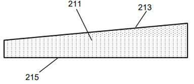
제1 캐리어 재료(211)는 제1 표면(213) 및 제1 표면(213)과 대향하는 제2 표면(215)을 포함한다. 제1 구획부(110)를 통한 제1 기류 경로(217)는 제1 캐리어 재료(211)의 제1 표면(213)에 걸쳐 연장된다.The
산 공급원(220)은 제2 구획부(120)에 위치되고 락트산으로 함침된 제2 캐리어 재료(221)를 포함한다. 이 예에서, 제2 캐리어 재료(221)는 약 20 mg의 락트산으로 함침된 다공성 세라믹 기재를 포함한다.The
제2 캐리어 재료(221)는 제1 표면(223) 및 제1 표면(223)과 대향하는 제2 표면(225)을 포함한다. 제2 구획부(120)를 통한 제2 기류 경로(227)는 제2 캐리어 재료(221)의 제1 표면(223)에 걸쳐 연장된다.The
도 4에 도시된 바와 같이, 제1 캐리어 재료(211) 및 제2 캐리어 재료(221) 각각은 제1 기류 경로(217) 및 제2 기류 경로(227)를 각각 따르는 방향으로 변화되는 두께를 갖는다. 도 4에 도시된 구현예에서, 제1 캐리어 재료(211)의 제1 표면(213) 및 제2 캐리어 재료(221)의 제1 표면(223) 각각을 볼록한 형상으로 제공함으로써, 제1 및 제2 캐리어 재료(211, 221)의 가변 두께가 달성된다.As shown in FIG. 4, each of the
도 5는 파형 형상을 갖는 제1 캐리어 재료(211)의 제1 표면(213)을 제공함으로써 제1 캐리어 재료(211)의 가변 두께가 달성되는 제1 캐리어 재료(211)에 대한 대안적인 형상을 도시한다. 동일한 형상이 제2 캐리어 재료(221)의 제1 표면(223)에 적용될 수 있다는 것을 이해할 것이다.5 shows an alternative shape for the
도 6은 오목한 형상을 갖는 제1 캐리어 재료(211)의 제1 표면(213)을 제공함으로써 제1 캐리어 재료(211)의 가변 두께가 달성되는 제1 캐리어 재료(211)에 대한 대안적인 형상을 도시한다. 동일한 형상이 제2 캐리어 재료(221)의 제1 표면(223)에 적용될 수 있다는 것을 이해할 것이다.6 shows an alternative shape for the
도 7은 제1 캐리어 재료(211)가 테이퍼진 형상을 갖도록 제1 캐리어 재료(211)의 제2 표면(215)에 대해 제1 캐리어 재료(211)의 제1 표면(213)을 경사지게 함으로써 제1 캐리어 재료(211)의 가변 두께가 달성되는 제1 캐리어 재료(211)에 대한 대안적인 형상을 도시한다. 동일한 형상이 제2 캐리어 재료(221)에 적용될 수 있다는 것을 이해할 것이다.7 shows a
도 8은 다면적 형상을 갖는 제1 표면(213)을 제공함으로써 제1 캐리어 재료(211)의 가변 두께가 달성되는 제1 캐리어 재료(211)에 대한 대안적인 형상을 도시한다. 특히, 제1 표면(213)은 경사 부분(270), 편평한 부분(272), 및 감소 부분(274)을 갖는다. 도 9에 도시된 예에서, 경사 부분(270)는 감소 부분(274)보다 짧아서 제1 표면(213)은 비대칭 형상을 갖는다. 동일한 형상이 제2 캐리어 재료(221)에 적용될 수 있다는 것을 이해할 것이다.FIG. 8 shows an alternative shape for the
도 9는 반구형 형상을 각각 갖는 복수의 함몰부(280)를 가진 제1 표면(213)을 제공함으로써 제1 캐리어 재료(211)의 가변 두께가 달성되는 제1 캐리어 재료(211)에 대한 대안적인 형상을 도시한다. 동일한 형상이 제2 캐리어 재료(221)에 적용될 수 있다는 것을 이해할 것이다.9 is an alternative to the
도 10은 반구형 형상을 각각 갖는 복수의 돌출부(290)를 가진 제1 표면(213)을 제공함으로써 제1 캐리어 재료(211)의 가변 두께가 달성되는 제1 캐리어 재료(211)에 대한 대안적인 형상을 도시한다. 동일한 형상이 제2 캐리어 재료(221)에 적용될 수 있다는 것을 이해할 것이다.FIG. 10 shows an alternative shape for the
Claims (15)
니코틴으로 함침된 제1 캐리어 재료를 포함하는 니코틴 공급원을 포함하는 제1 구획부로서, 상기 제1 구획부는 제1 공기 유입구 및 제1 공기 배출구를 갖고, 상기 제1 구획부는 상기 제1 공기 유입구와 상기 제1 공기 배출구 사이에서 상기 제1 캐리어 재료의 제1 표면에 걸쳐 연장되는 제1 기류 경로를 정의하는, 제1 구획부; 및
산(acid)으로 함침된 제2 캐리어 재료를 포함하는 산 공급원을 포함하는 제2 구획부로서, 상기 제2 구획부는 제2 공기 유입구 및 제2 공기 배출구를 갖고, 상기 제2 구획부는 상기 제2 공기 유입구와 상기 제2 공기 배출구 사이에서 상기 제2 캐리어 재료의 제1 표면에 걸쳐 연장되는 제2 기류 경로를 정의하는, 제2 구획부를 포함하며;
상기 제1 구획부 및 상기 제2 구획부는 상기 카트리지 내에 병렬로 배열되고;
상기 제1 캐리어 재료 및 상기 제2 캐리어 재료 중 적어도 하나의 두께는 상기 제1 기류 경로 또는 상기 제2 기류 경로를 각각 따르는 방향으로 변화되는, 카트리지.A cartridge for use in an aerosol-generating system for the generation of an aerosol comprising nicotine salt particles, the cartridge comprising:
A first compartment comprising a nicotine source comprising a first carrier material impregnated with nicotine, the first compartment having a first air inlet and a first air outlet, the first compartment and the first air inlet and A first compartment defining a first airflow path extending over the first surface of the first carrier material between the first air outlets; And
A second compartment comprising an acid source comprising a second carrier material impregnated with acid, the second compartment having a second air inlet and a second air outlet, and the second compartment A second partition defining a second airflow path extending over the first surface of the second carrier material between the air inlet and the second air outlet;
The first partition and the second partition are arranged in parallel in the cartridge;
The cartridge, wherein the thickness of at least one of the first carrier material and the second carrier material is varied in a direction along the first airflow path or the second airflow path, respectively.
제1항 내지 제13항 중 어느 한 항에 따른 카트리지; 및
에어로졸 발생 장치를 포함하며, 상기 에어로졸 발생 장치는:
상기 카트리지의 적어도 일부를 수용하기 위한 공동을 정의하는 장치 하우징; 및
상기 카트리지의 제1 구획부 및 제2 구획부를 가열하기 위한 히터를 포함하는, 에어로졸 발생 시스템.As an aerosol-generating system:
A cartridge according to any one of claims 1 to 13; And
An aerosol-generating device comprising:
An apparatus housing defining a cavity for receiving at least a portion of the cartridge; And
A heater for heating the first and second compartments of the cartridge.
Applications Claiming Priority (3)
| Application Number | Priority Date | Filing Date | Title |
|---|---|---|---|
| EP18180841 | 2018-06-29 | ||
| EP18180841.1 | 2018-06-29 | ||
| PCT/EP2019/067465 WO2020002671A1 (en) | 2018-06-29 | 2019-06-28 | A cartridge for an aerosol-generating system |
Publications (1)
| Publication Number | Publication Date |
|---|---|
| KR20210024465A true KR20210024465A (en) | 2021-03-05 |
Family
ID=62837759
Family Applications (1)
| Application Number | Title | Priority Date | Filing Date |
|---|---|---|---|
| KR1020207036064A KR20210024465A (en) | 2018-06-29 | 2019-06-28 | Cartridges for aerosol-generating systems |
Country Status (6)
| Country | Link |
|---|---|
| US (1) | US11937632B2 (en) |
| EP (1) | EP3813578B1 (en) |
| JP (1) | JP7393356B2 (en) |
| KR (1) | KR20210024465A (en) |
| CN (1) | CN112272524B (en) |
| WO (1) | WO2020002671A1 (en) |
Families Citing this family (2)
| Publication number | Priority date | Publication date | Assignee | Title |
|---|---|---|---|---|
| US11937632B2 (en) * | 2018-06-29 | 2024-03-26 | Philip Morris Products S.A. | Cartridge for an aerosol-generating system |
| KR20210032949A (en) * | 2018-07-24 | 2021-03-25 | 필립모리스 프로덕츠 에스.에이. | Carrier material with inner channel |
Family Cites Families (25)
| Publication number | Priority date | Publication date | Assignee | Title |
|---|---|---|---|---|
| US4765348A (en) | 1986-12-12 | 1988-08-23 | Brown & Williamson Tobacco Corporation | Non-combustible simulated cigarette device |
| US20140350668A1 (en) | 2013-03-13 | 2014-11-27 | Symetis Sa | Prosthesis Seals and Methods for Sealing an Expandable Prosthesis |
| MX360805B (en) | 2013-03-15 | 2018-11-16 | Philip Morris Products Sa | Aerosol-generating system with differential heating. |
| WO2014140087A1 (en) * | 2013-03-15 | 2014-09-18 | Philip Morris Products S.A. | Aerosol-generating system having a piercing element |
| US11426544B2 (en) | 2013-05-21 | 2022-08-30 | Philip Morris Products S.A. | Aerosol-generating system comprising a delivery enhancing compound source and a medicament source |
| UA117370C2 (en) * | 2013-07-03 | 2018-07-25 | Філіп Морріс Продактс С.А. | AEROSOL GENERATING MULTIPLE APPLICATION |
| GB201423316D0 (en) | 2014-12-29 | 2015-02-11 | British American Tobacco Co | Cartridge for use with apparatus for heating smokable material |
| GB201501429D0 (en) | 2015-01-28 | 2015-03-11 | British American Tobacco Co | Apparatus for heating aerosol generating material |
| CN108601397A (en) * | 2015-08-17 | 2018-09-28 | 菲利普莫里斯生产公司 | Aerosol generates system and the aerosol for this kind of system generates product |
| JP6903646B2 (en) * | 2015-10-22 | 2021-07-14 | フィリップ・モーリス・プロダクツ・ソシエテ・アノニム | Aerosol-generating articles and methods, aerosol generators and systems for manufacturing such aerosol-generating articles. |
| KR20240042236A (en) * | 2015-12-22 | 2024-04-01 | 필립모리스 프로덕츠 에스.에이. | A cartridge for an aerosol-generating system and an aerosol-generating system comprising a cartridge |
| LT3183979T (en) | 2015-12-22 | 2018-07-10 | Philip Morris Products S.A. | Cartridge for an aerosol-generating system and an aerosol-generating system comprising a cartridge |
| PL3183980T3 (en) | 2015-12-22 | 2019-02-28 | Philip Morris Products S.A. | A cartridge for an aerosol-generating system and an aerosol-generating system comprising a cartridge |
| RU2730149C2 (en) | 2016-06-08 | 2020-08-19 | Филип Моррис Продактс С.А. | Electrically controlled system which generates aerosol with multi-component aerosol-generating article |
| US10306927B2 (en) | 2016-07-28 | 2019-06-04 | Altria Client Services Llc | Venturi effect-driven formulation delivery in e-vaping devices |
| CA3038236A1 (en) * | 2016-11-30 | 2018-06-07 | Philip Morris Products S.A. | Aerosol-generating system having an outer housing |
| EP3801090B1 (en) | 2018-06-07 | 2022-08-03 | Philip Morris Products S.A. | An aerosol generating system, aerosol forming device and a cartridge therefor |
| ES2933564T3 (en) | 2018-06-21 | 2023-02-10 | Philip Morris Products Sa | Resealable cartridge unit for an aerosol generating system |
| CN112261883B (en) * | 2018-06-29 | 2024-04-02 | 菲利普莫里斯生产公司 | Aerosol generating system with enhanced aerosol delivery |
| US11937632B2 (en) * | 2018-06-29 | 2024-03-26 | Philip Morris Products S.A. | Cartridge for an aerosol-generating system |
| KR20210031895A (en) | 2018-07-24 | 2021-03-23 | 필립모리스 프로덕츠 에스.에이. | Cartridges with non-uniform cavities |
| KR20210032949A (en) | 2018-07-24 | 2021-03-25 | 필립모리스 프로덕츠 에스.에이. | Carrier material with inner channel |
| CN112423611B (en) | 2018-07-26 | 2024-03-01 | 菲利普莫里斯生产公司 | Improved aerosol-generating system comprising individually activatable heating elements |
| BR112022011593A2 (en) * | 2019-12-18 | 2022-08-30 | Philip Morris Products Sa | FORMULATION FOR USE IN AN AEROSOL GENERATING SYSTEM |
| EP4076025A1 (en) * | 2019-12-18 | 2022-10-26 | Philip Morris Products, S.A. | A formulation for use in an aerosol-generating system |
-
2019
- 2019-06-28 US US16/973,826 patent/US11937632B2/en active Active
- 2019-06-28 CN CN201980037882.XA patent/CN112272524B/en active Active
- 2019-06-28 JP JP2020568770A patent/JP7393356B2/en active Active
- 2019-06-28 KR KR1020207036064A patent/KR20210024465A/en unknown
- 2019-06-28 WO PCT/EP2019/067465 patent/WO2020002671A1/en active Application Filing
- 2019-06-28 EP EP19734790.9A patent/EP3813578B1/en active Active
Also Published As
| Publication number | Publication date |
|---|---|
| US11937632B2 (en) | 2024-03-26 |
| JP2021528056A (en) | 2021-10-21 |
| EP3813578B1 (en) | 2022-04-27 |
| WO2020002671A1 (en) | 2020-01-02 |
| US20210244091A1 (en) | 2021-08-12 |
| EP3813578A1 (en) | 2021-05-05 |
| CN112272524A (en) | 2021-01-26 |
| JP7393356B2 (en) | 2023-12-06 |
| CN112272524B (en) | 2024-04-02 |
Similar Documents
| Publication | Publication Date | Title |
|---|---|---|
| RU2651452C1 (en) | Cartridge for aerosol-generating system and aerosol generating system comprising a cartridge | |
| RU2644107C1 (en) | Cartridge for aerosol-generating system and system, generating aerosol, containing cartridge | |
| RU2702397C2 (en) | Aerosol-generating system and aerosol-generating article for use in such system | |
| CN108289509B (en) | Cartridge for an aerosol-generating system and aerosol-generating system comprising a cartridge | |
| CN108289511B (en) | Cartridge for an aerosol-generating system and aerosol-generating system comprising a cartridge | |
| JP7204691B2 (en) | Cartridge assembly with vent airflow | |
| RU2763273C2 (en) | Aerosol generating system with ventilation air flow | |
| US11857717B2 (en) | Aerosol generating system with enhanced aerosol delivery | |
| JP7467405B2 (en) | Carrier material having internal channels | |
| EP3813578B1 (en) | A cartridge for an aerosol-generating system | |
| EP3826490B1 (en) | A cartridge having a non-uniform cavity | |
| RU2795758C2 (en) | Aerosol-generating system and cartridge for aerosol-generating system | |
| RU2792868C2 (en) | Cartridge with a heterogeneous cavity | |
| RU2803207C2 (en) | Aerosol generating system and cartridge for such system | |
| RU2784753C2 (en) | Repeatedly sealed cartridge assembly for aerosol generating system |