JP2023544040A - Aerosol generating article with front end plug - Google Patents
Aerosol generating article with front end plug Download PDFInfo
- Publication number
- JP2023544040A JP2023544040A JP2023520186A JP2023520186A JP2023544040A JP 2023544040 A JP2023544040 A JP 2023544040A JP 2023520186 A JP2023520186 A JP 2023520186A JP 2023520186 A JP2023520186 A JP 2023520186A JP 2023544040 A JP2023544040 A JP 2023544040A
- Authority
- JP
- Japan
- Prior art keywords
- aerosol
- generating
- section
- generating article
- downstream
- Prior art date
- Legal status (The legal status is an assumption and is not a legal conclusion. Google has not performed a legal analysis and makes no representation as to the accuracy of the status listed.)
- Pending
Links
- 239000000443 aerosol Substances 0.000 title claims abstract description 414
- 239000000758 substrate Substances 0.000 claims abstract description 248
- 238000011144 upstream manufacturing Methods 0.000 claims abstract description 198
- 238000009423 ventilation Methods 0.000 claims description 107
- 229920002301 cellulose acetate Polymers 0.000 claims description 20
- 238000010586 diagram Methods 0.000 abstract 1
- 239000000463 material Substances 0.000 description 112
- 235000002637 Nicotiana tabacum Nutrition 0.000 description 106
- 241000208125 Nicotiana Species 0.000 description 102
- 241000196324 Embryophyta Species 0.000 description 75
- 238000010438 heat treatment Methods 0.000 description 47
- 239000000945 filler Substances 0.000 description 46
- 239000000123 paper Substances 0.000 description 39
- PEDCQBHIVMGVHV-UHFFFAOYSA-N Glycerine Chemical compound OCC(O)CO PEDCQBHIVMGVHV-UHFFFAOYSA-N 0.000 description 33
- 239000002245 particle Substances 0.000 description 31
- 239000000499 gel Substances 0.000 description 28
- 239000000203 mixture Substances 0.000 description 28
- SNICXCGAKADSCV-JTQLQIEISA-N (-)-Nicotine Chemical compound CN1CCC[C@H]1C1=CC=CN=C1 SNICXCGAKADSCV-JTQLQIEISA-N 0.000 description 23
- 150000001875 compounds Chemical class 0.000 description 21
- SNICXCGAKADSCV-UHFFFAOYSA-N nicotine Natural products CN1CCCC1C1=CC=CN=C1 SNICXCGAKADSCV-UHFFFAOYSA-N 0.000 description 20
- 229960002715 nicotine Drugs 0.000 description 20
- 229930013930 alkaloid Natural products 0.000 description 18
- DNIAPMSPPWPWGF-UHFFFAOYSA-N Propylene glycol Chemical compound CC(O)CO DNIAPMSPPWPWGF-UHFFFAOYSA-N 0.000 description 15
- -1 alkaloid compound Chemical class 0.000 description 14
- 229930003827 cannabinoid Natural products 0.000 description 14
- 239000003557 cannabinoid Substances 0.000 description 14
- 235000011187 glycerol Nutrition 0.000 description 13
- 229920002678 cellulose Polymers 0.000 description 11
- 239000001913 cellulose Substances 0.000 description 11
- 238000004519 manufacturing process Methods 0.000 description 11
- 238000013022 venting Methods 0.000 description 11
- 238000010899 nucleation Methods 0.000 description 10
- 230000006911 nucleation Effects 0.000 description 10
- QGZKDVFQNNGYKY-UHFFFAOYSA-N Ammonia Chemical compound N QGZKDVFQNNGYKY-UHFFFAOYSA-N 0.000 description 9
- 238000001816 cooling Methods 0.000 description 9
- 238000000034 method Methods 0.000 description 8
- 235000019504 cigarettes Nutrition 0.000 description 7
- 230000002093 peripheral effect Effects 0.000 description 7
- 239000012071 phase Substances 0.000 description 7
- 230000000391 smoking effect Effects 0.000 description 7
- 244000061176 Nicotiana tabacum Species 0.000 description 6
- 125000003118 aryl group Chemical group 0.000 description 6
- 230000015572 biosynthetic process Effects 0.000 description 6
- 238000009833 condensation Methods 0.000 description 6
- 230000005494 condensation Effects 0.000 description 6
- 230000005672 electromagnetic field Effects 0.000 description 6
- 238000012546 transfer Methods 0.000 description 6
- 238000001704 evaporation Methods 0.000 description 5
- 230000008020 evaporation Effects 0.000 description 5
- 239000007788 liquid Substances 0.000 description 5
- 239000011148 porous material Substances 0.000 description 5
- 239000007787 solid Substances 0.000 description 5
- 235000000346 sugar Nutrition 0.000 description 5
- XLYOFNOQVPJJNP-UHFFFAOYSA-N water Substances O XLYOFNOQVPJJNP-UHFFFAOYSA-N 0.000 description 5
- PUPZLCDOIYMWBV-UHFFFAOYSA-N (+/-)-1,3-Butanediol Chemical compound CC(O)CCO PUPZLCDOIYMWBV-UHFFFAOYSA-N 0.000 description 4
- IJGRMHOSHXDMSA-UHFFFAOYSA-N Atomic nitrogen Chemical compound N#N IJGRMHOSHXDMSA-UHFFFAOYSA-N 0.000 description 4
- PXHVJJICTQNCMI-UHFFFAOYSA-N Nickel Chemical compound [Ni] PXHVJJICTQNCMI-UHFFFAOYSA-N 0.000 description 4
- 239000004372 Polyvinyl alcohol Substances 0.000 description 4
- 229910052782 aluminium Inorganic materials 0.000 description 4
- XAGFODPZIPBFFR-UHFFFAOYSA-N aluminium Chemical compound [Al] XAGFODPZIPBFFR-UHFFFAOYSA-N 0.000 description 4
- 229910021529 ammonia Inorganic materials 0.000 description 4
- 230000008901 benefit Effects 0.000 description 4
- 229920000704 biodegradable plastic Polymers 0.000 description 4
- 229920003086 cellulose ether Polymers 0.000 description 4
- ZDJFDFNNEAPGOP-UHFFFAOYSA-N dimethyl tetradecanedioate Chemical compound COC(=O)CCCCCCCCCCCCC(=O)OC ZDJFDFNNEAPGOP-UHFFFAOYSA-N 0.000 description 4
- 238000001125 extrusion Methods 0.000 description 4
- 230000005294 ferromagnetic effect Effects 0.000 description 4
- 239000000835 fiber Substances 0.000 description 4
- 239000007789 gas Substances 0.000 description 4
- 230000001976 improved effect Effects 0.000 description 4
- 230000001965 increasing effect Effects 0.000 description 4
- 230000006698 induction Effects 0.000 description 4
- 230000014759 maintenance of location Effects 0.000 description 4
- 229910052757 nitrogen Inorganic materials 0.000 description 4
- 125000004433 nitrogen atom Chemical group N* 0.000 description 4
- 229920002451 polyvinyl alcohol Polymers 0.000 description 4
- 235000019422 polyvinyl alcohol Nutrition 0.000 description 4
- 230000008569 process Effects 0.000 description 4
- 230000001953 sensory effect Effects 0.000 description 4
- 230000004888 barrier function Effects 0.000 description 3
- 238000002485 combustion reaction Methods 0.000 description 3
- 230000000694 effects Effects 0.000 description 3
- 238000001914 filtration Methods 0.000 description 3
- 239000000796 flavoring agent Substances 0.000 description 3
- 239000012530 fluid Substances 0.000 description 3
- 230000002209 hydrophobic effect Effects 0.000 description 3
- 230000001939 inductive effect Effects 0.000 description 3
- 229910052751 metal Inorganic materials 0.000 description 3
- 239000002184 metal Substances 0.000 description 3
- 229920000747 poly(lactic acid) Polymers 0.000 description 3
- 239000004626 polylactic acid Substances 0.000 description 3
- 230000009467 reduction Effects 0.000 description 3
- 230000035807 sensation Effects 0.000 description 3
- 235000019615 sensations Nutrition 0.000 description 3
- 150000005846 sugar alcohols Polymers 0.000 description 3
- KMZHZAAOEWVPSE-UHFFFAOYSA-N 2,3-dihydroxypropyl acetate Chemical compound CC(=O)OCC(O)CO KMZHZAAOEWVPSE-UHFFFAOYSA-N 0.000 description 2
- 241000218236 Cannabis Species 0.000 description 2
- OKTJSMMVPCPJKN-UHFFFAOYSA-N Carbon Chemical compound [C] OKTJSMMVPCPJKN-UHFFFAOYSA-N 0.000 description 2
- 229920002134 Carboxymethyl cellulose Polymers 0.000 description 2
- XEEYBQQBJWHFJM-UHFFFAOYSA-N Iron Chemical compound [Fe] XEEYBQQBJWHFJM-UHFFFAOYSA-N 0.000 description 2
- CYQFCXCEBYINGO-UHFFFAOYSA-N THC Natural products C1=C(C)CCC2C(C)(C)OC3=CC(CCCCC)=CC(O)=C3C21 CYQFCXCEBYINGO-UHFFFAOYSA-N 0.000 description 2
- QHMBSVQNZZTUGM-UHFFFAOYSA-N Trans-Cannabidiol Natural products OC1=CC(CCCCC)=CC(O)=C1C1C(C(C)=C)CCC(C)=C1 QHMBSVQNZZTUGM-UHFFFAOYSA-N 0.000 description 2
- 239000002253 acid Substances 0.000 description 2
- 150000007513 acids Chemical class 0.000 description 2
- 238000005273 aeration Methods 0.000 description 2
- 230000002776 aggregation Effects 0.000 description 2
- 125000001931 aliphatic group Chemical group 0.000 description 2
- 230000009286 beneficial effect Effects 0.000 description 2
- QHMBSVQNZZTUGM-ZWKOTPCHSA-N cannabidiol Chemical compound OC1=CC(CCCCC)=CC(O)=C1[C@H]1[C@H](C(C)=C)CCC(C)=C1 QHMBSVQNZZTUGM-ZWKOTPCHSA-N 0.000 description 2
- 229950011318 cannabidiol Drugs 0.000 description 2
- ZTGXAWYVTLUPDT-UHFFFAOYSA-N cannabidiol Natural products OC1=CC(CCCCC)=CC(O)=C1C1C(C(C)=C)CC=C(C)C1 ZTGXAWYVTLUPDT-UHFFFAOYSA-N 0.000 description 2
- 229940065144 cannabinoids Drugs 0.000 description 2
- 238000005266 casting Methods 0.000 description 2
- 239000000919 ceramic Substances 0.000 description 2
- 238000004891 communication Methods 0.000 description 2
- 230000003750 conditioning effect Effects 0.000 description 2
- 238000010276 construction Methods 0.000 description 2
- 238000005520 cutting process Methods 0.000 description 2
- 230000007423 decrease Effects 0.000 description 2
- CYQFCXCEBYINGO-IAGOWNOFSA-N delta1-THC Chemical compound C1=C(C)CC[C@H]2C(C)(C)OC3=CC(CCCCC)=CC(O)=C3[C@@H]21 CYQFCXCEBYINGO-IAGOWNOFSA-N 0.000 description 2
- PCXRACLQFPRCBB-ZWKOTPCHSA-N dihydrocannabidiol Natural products OC1=CC(CCCCC)=CC(O)=C1[C@H]1[C@H](C(C)C)CCC(C)=C1 PCXRACLQFPRCBB-ZWKOTPCHSA-N 0.000 description 2
- 238000010790 dilution Methods 0.000 description 2
- 239000012895 dilution Substances 0.000 description 2
- 238000009826 distribution Methods 0.000 description 2
- 238000005553 drilling Methods 0.000 description 2
- 229960004242 dronabinol Drugs 0.000 description 2
- 238000001035 drying Methods 0.000 description 2
- 238000005265 energy consumption Methods 0.000 description 2
- 150000002148 esters Chemical class 0.000 description 2
- 239000003302 ferromagnetic material Substances 0.000 description 2
- 235000019634 flavors Nutrition 0.000 description 2
- 238000009472 formulation Methods 0.000 description 2
- 239000012634 fragment Substances 0.000 description 2
- 230000004927 fusion Effects 0.000 description 2
- 239000003349 gelling agent Substances 0.000 description 2
- 239000007791 liquid phase Substances 0.000 description 2
- 229920001684 low density polyethylene Polymers 0.000 description 2
- 239000004702 low-density polyethylene Substances 0.000 description 2
- 230000005291 magnetic effect Effects 0.000 description 2
- 238000005259 measurement Methods 0.000 description 2
- 229910052759 nickel Inorganic materials 0.000 description 2
- 230000035699 permeability Effects 0.000 description 2
- 229920000642 polymer Polymers 0.000 description 2
- 229920001296 polysiloxane Polymers 0.000 description 2
- 239000000047 product Substances 0.000 description 2
- 239000000779 smoke Substances 0.000 description 2
- 241000894007 species Species 0.000 description 2
- 239000010935 stainless steel Substances 0.000 description 2
- 229910001220 stainless steel Inorganic materials 0.000 description 2
- 238000003860 storage Methods 0.000 description 2
- 239000000126 substance Substances 0.000 description 2
- ILJSQTXMGCGYMG-UHFFFAOYSA-N triacetic acid Chemical compound CC(=O)CC(=O)CC(O)=O ILJSQTXMGCGYMG-UHFFFAOYSA-N 0.000 description 2
- ZIBGPFATKBEMQZ-UHFFFAOYSA-N triethylene glycol Chemical compound OCCOCCOCCO ZIBGPFATKBEMQZ-UHFFFAOYSA-N 0.000 description 2
- 235000013311 vegetables Nutrition 0.000 description 2
- LNAZSHAWQACDHT-XIYTZBAFSA-N (2r,3r,4s,5r,6s)-4,5-dimethoxy-2-(methoxymethyl)-3-[(2s,3r,4s,5r,6r)-3,4,5-trimethoxy-6-(methoxymethyl)oxan-2-yl]oxy-6-[(2r,3r,4s,5r,6r)-4,5,6-trimethoxy-2-(methoxymethyl)oxan-3-yl]oxyoxane Chemical compound CO[C@@H]1[C@@H](OC)[C@H](OC)[C@@H](COC)O[C@H]1O[C@H]1[C@H](OC)[C@@H](OC)[C@H](O[C@H]2[C@@H]([C@@H](OC)[C@H](OC)O[C@@H]2COC)OC)O[C@@H]1COC LNAZSHAWQACDHT-XIYTZBAFSA-N 0.000 description 1
- HYXZLSCUMKOHAE-UHFFFAOYSA-N 2,2-dimethyldodecanedioic acid Chemical compound OC(=O)C(C)(C)CCCCCCCCCC(O)=O HYXZLSCUMKOHAE-UHFFFAOYSA-N 0.000 description 1
- 240000005475 Abelmoschus moschatus Species 0.000 description 1
- SOPPBXUYQGUQHE-JTQLQIEISA-N Anatabine Chemical compound C1C=CCN[C@@H]1C1=CC=CN=C1 SOPPBXUYQGUQHE-JTQLQIEISA-N 0.000 description 1
- SOPPBXUYQGUQHE-UHFFFAOYSA-N Anatabine Natural products C1C=CCNC1C1=CC=CN=C1 SOPPBXUYQGUQHE-UHFFFAOYSA-N 0.000 description 1
- 244000025254 Cannabis sativa Species 0.000 description 1
- 235000008697 Cannabis sativa Nutrition 0.000 description 1
- 229920003043 Cellulose fiber Polymers 0.000 description 1
- 239000001856 Ethyl cellulose Substances 0.000 description 1
- ZZSNKZQZMQGXPY-UHFFFAOYSA-N Ethyl cellulose Chemical compound CCOCC1OC(OC)C(OCC)C(OCC)C1OC1C(O)C(O)C(OC)C(CO)O1 ZZSNKZQZMQGXPY-UHFFFAOYSA-N 0.000 description 1
- RFSUNEUAIZKAJO-ARQDHWQXSA-N Fructose Chemical compound OC[C@H]1O[C@](O)(CO)[C@@H](O)[C@@H]1O RFSUNEUAIZKAJO-ARQDHWQXSA-N 0.000 description 1
- 229930091371 Fructose Natural products 0.000 description 1
- 239000005715 Fructose Substances 0.000 description 1
- 241000233866 Fungi Species 0.000 description 1
- WQZGKKKJIJFFOK-GASJEMHNSA-N Glucose Natural products OC[C@H]1OC(O)[C@H](O)[C@@H](O)[C@@H]1O WQZGKKKJIJFFOK-GASJEMHNSA-N 0.000 description 1
- UXDDRFCJKNROTO-UHFFFAOYSA-N Glycerol 1,2-diacetate Chemical compound CC(=O)OCC(CO)OC(C)=O UXDDRFCJKNROTO-UHFFFAOYSA-N 0.000 description 1
- UFHFLCQGNIYNRP-UHFFFAOYSA-N Hydrogen Chemical compound [H][H] UFHFLCQGNIYNRP-UHFFFAOYSA-N 0.000 description 1
- 229920000663 Hydroxyethyl cellulose Polymers 0.000 description 1
- 241000218922 Magnoliophyta Species 0.000 description 1
- 235000006679 Mentha X verticillata Nutrition 0.000 description 1
- 235000002899 Mentha suaveolens Nutrition 0.000 description 1
- 235000001636 Mentha x rotundifolia Nutrition 0.000 description 1
- ZOKXTWBITQBERF-UHFFFAOYSA-N Molybdenum Chemical compound [Mo] ZOKXTWBITQBERF-UHFFFAOYSA-N 0.000 description 1
- 229920002472 Starch Polymers 0.000 description 1
- 229910000831 Steel Inorganic materials 0.000 description 1
- 235000016639 Syzygium aromaticum Nutrition 0.000 description 1
- 244000223014 Syzygium aromaticum Species 0.000 description 1
- 244000269722 Thea sinensis Species 0.000 description 1
- RTAQQCXQSZGOHL-UHFFFAOYSA-N Titanium Chemical compound [Ti] RTAQQCXQSZGOHL-UHFFFAOYSA-N 0.000 description 1
- 238000010521 absorption reaction Methods 0.000 description 1
- 238000010669 acid-base reaction Methods 0.000 description 1
- 230000009471 action Effects 0.000 description 1
- 230000001154 acute effect Effects 0.000 description 1
- 239000000853 adhesive Substances 0.000 description 1
- 230000001070 adhesive effect Effects 0.000 description 1
- 230000002411 adverse Effects 0.000 description 1
- 238000005054 agglomeration Methods 0.000 description 1
- 238000004220 aggregation Methods 0.000 description 1
- 150000003797 alkaloid derivatives Chemical class 0.000 description 1
- 229910045601 alloy Inorganic materials 0.000 description 1
- 239000000956 alloy Substances 0.000 description 1
- 150000001412 amines Chemical class 0.000 description 1
- QVGXLLKOCUKJST-UHFFFAOYSA-N atomic oxygen Chemical compound [O] QVGXLLKOCUKJST-UHFFFAOYSA-N 0.000 description 1
- 239000002585 base Substances 0.000 description 1
- 230000006399 behavior Effects 0.000 description 1
- WQZGKKKJIJFFOK-VFUOTHLCSA-N beta-D-glucose Chemical compound OC[C@H]1O[C@@H](O)[C@H](O)[C@@H](O)[C@@H]1O WQZGKKKJIJFFOK-VFUOTHLCSA-N 0.000 description 1
- 239000006227 byproduct Substances 0.000 description 1
- 244000213578 camo Species 0.000 description 1
- 235000009120 camo Nutrition 0.000 description 1
- 229910052799 carbon Inorganic materials 0.000 description 1
- 239000001768 carboxy methyl cellulose Substances 0.000 description 1
- 235000010948 carboxy methyl cellulose Nutrition 0.000 description 1
- 239000008112 carboxymethyl-cellulose Substances 0.000 description 1
- 230000008859 change Effects 0.000 description 1
- 235000005607 chanvre indien Nutrition 0.000 description 1
- 230000001055 chewing effect Effects 0.000 description 1
- 235000019506 cigar Nutrition 0.000 description 1
- 239000011248 coating agent Substances 0.000 description 1
- 238000000576 coating method Methods 0.000 description 1
- 230000001427 coherent effect Effects 0.000 description 1
- 230000000295 complement effect Effects 0.000 description 1
- 239000002131 composite material Substances 0.000 description 1
- 238000005336 cracking Methods 0.000 description 1
- 125000004122 cyclic group Chemical group 0.000 description 1
- 238000013461 design Methods 0.000 description 1
- IZMOTZDBVPMOFE-UHFFFAOYSA-N dimethyl dodecanedioate Chemical compound COC(=O)CCCCCCCCCCC(=O)OC IZMOTZDBVPMOFE-UHFFFAOYSA-N 0.000 description 1
- 238000006073 displacement reaction Methods 0.000 description 1
- 239000000428 dust Substances 0.000 description 1
- 230000007613 environmental effect Effects 0.000 description 1
- 229920001249 ethyl cellulose Polymers 0.000 description 1
- 235000019325 ethyl cellulose Nutrition 0.000 description 1
- 230000002349 favourable effect Effects 0.000 description 1
- 239000002657 fibrous material Substances 0.000 description 1
- 239000012467 final product Substances 0.000 description 1
- 235000013355 food flavoring agent Nutrition 0.000 description 1
- 239000012458 free base Substances 0.000 description 1
- 239000000446 fuel Substances 0.000 description 1
- 230000006870 function Effects 0.000 description 1
- 239000008246 gaseous mixture Substances 0.000 description 1
- 239000008103 glucose Substances 0.000 description 1
- 239000008187 granular material Substances 0.000 description 1
- 229910002804 graphite Inorganic materials 0.000 description 1
- 239000010439 graphite Substances 0.000 description 1
- 238000000227 grinding Methods 0.000 description 1
- 239000003779 heat-resistant material Substances 0.000 description 1
- 125000000623 heterocyclic group Chemical group 0.000 description 1
- 239000001866 hydroxypropyl methyl cellulose Substances 0.000 description 1
- 229920003088 hydroxypropyl methyl cellulose Polymers 0.000 description 1
- 235000010979 hydroxypropyl methyl cellulose Nutrition 0.000 description 1
- UFVKGYZPFZQRLF-UHFFFAOYSA-N hydroxypropyl methyl cellulose Chemical compound OC1C(O)C(OC)OC(CO)C1OC1C(O)C(O)C(OC2C(C(O)C(OC3C(C(O)C(O)C(CO)O3)O)C(CO)O2)O)C(CO)O1 UFVKGYZPFZQRLF-UHFFFAOYSA-N 0.000 description 1
- 238000007654 immersion Methods 0.000 description 1
- 238000011065 in-situ storage Methods 0.000 description 1
- 230000000977 initiatory effect Effects 0.000 description 1
- 238000002347 injection Methods 0.000 description 1
- 239000007924 injection Substances 0.000 description 1
- 238000001746 injection moulding Methods 0.000 description 1
- 230000003993 interaction Effects 0.000 description 1
- 229910052742 iron Inorganic materials 0.000 description 1
- 239000002648 laminated material Substances 0.000 description 1
- 238000003475 lamination Methods 0.000 description 1
- 210000004072 lung Anatomy 0.000 description 1
- 240000004308 marijuana Species 0.000 description 1
- 230000007246 mechanism Effects 0.000 description 1
- 239000007769 metal material Substances 0.000 description 1
- 229920000609 methyl cellulose Polymers 0.000 description 1
- 239000001923 methylcellulose Substances 0.000 description 1
- 235000010981 methylcellulose Nutrition 0.000 description 1
- 238000002156 mixing Methods 0.000 description 1
- 229910052750 molybdenum Inorganic materials 0.000 description 1
- 239000011733 molybdenum Substances 0.000 description 1
- 238000000465 moulding Methods 0.000 description 1
- 229910052758 niobium Inorganic materials 0.000 description 1
- 239000010955 niobium Substances 0.000 description 1
- GUCVJGMIXFAOAE-UHFFFAOYSA-N niobium atom Chemical compound [Nb] GUCVJGMIXFAOAE-UHFFFAOYSA-N 0.000 description 1
- 230000009965 odorless effect Effects 0.000 description 1
- 150000002894 organic compounds Chemical class 0.000 description 1
- 239000001301 oxygen Substances 0.000 description 1
- 229910052760 oxygen Inorganic materials 0.000 description 1
- 239000002907 paramagnetic material Substances 0.000 description 1
- 239000011088 parchment paper Substances 0.000 description 1
- 239000013618 particulate matter Substances 0.000 description 1
- 239000008188 pellet Substances 0.000 description 1
- 239000005014 poly(hydroxyalkanoate) Substances 0.000 description 1
- 238000002360 preparation method Methods 0.000 description 1
- 238000012545 processing Methods 0.000 description 1
- 239000005871 repellent Substances 0.000 description 1
- 238000012827 research and development Methods 0.000 description 1
- 238000000926 separation method Methods 0.000 description 1
- HBMJWWWQQXIZIP-UHFFFAOYSA-N silicon carbide Chemical compound [Si+]#[C-] HBMJWWWQQXIZIP-UHFFFAOYSA-N 0.000 description 1
- 229910010271 silicon carbide Inorganic materials 0.000 description 1
- 239000000243 solution Substances 0.000 description 1
- 238000005507 spraying Methods 0.000 description 1
- 239000008107 starch Substances 0.000 description 1
- 235000019698 starch Nutrition 0.000 description 1
- 239000010959 steel Substances 0.000 description 1
- 150000008163 sugars Chemical class 0.000 description 1
- 238000004381 surface treatment Methods 0.000 description 1
- 210000004243 sweat Anatomy 0.000 description 1
- 230000009967 tasteless effect Effects 0.000 description 1
- 235000013616 tea Nutrition 0.000 description 1
- 238000010998 test method Methods 0.000 description 1
- 238000012360 testing method Methods 0.000 description 1
- 238000005979 thermal decomposition reaction Methods 0.000 description 1
- 239000010936 titanium Substances 0.000 description 1
- 229910052719 titanium Inorganic materials 0.000 description 1
- 210000003462 vein Anatomy 0.000 description 1
- 239000000341 volatile oil Substances 0.000 description 1
- 239000000080 wetting agent Substances 0.000 description 1
- 230000037303 wrinkles Effects 0.000 description 1
- 239000010457 zeolite Substances 0.000 description 1
- 229910000859 α-Fe Inorganic materials 0.000 description 1
Images

Classifications
-
- A—HUMAN NECESSITIES
- A24—TOBACCO; CIGARS; CIGARETTES; SIMULATED SMOKING DEVICES; SMOKERS' REQUISITES
- A24D—CIGARS; CIGARETTES; TOBACCO SMOKE FILTERS; MOUTHPIECES FOR CIGARS OR CIGARETTES; MANUFACTURE OF TOBACCO SMOKE FILTERS OR MOUTHPIECES
- A24D1/00—Cigars; Cigarettes
- A24D1/20—Cigarettes specially adapted for simulated smoking devices
-
- A—HUMAN NECESSITIES
- A24—TOBACCO; CIGARS; CIGARETTES; SIMULATED SMOKING DEVICES; SMOKERS' REQUISITES
- A24C—MACHINES FOR MAKING CIGARS OR CIGARETTES
- A24C5/00—Making cigarettes; Making tipping materials for, or attaching filters or mouthpieces to, cigars or cigarettes
- A24C5/14—Machines of the continuous-rod type
- A24C5/18—Forming the rod
- A24C5/1885—Forming the rod for cigarettes with an axial air duct
-
- A—HUMAN NECESSITIES
- A24—TOBACCO; CIGARS; CIGARETTES; SIMULATED SMOKING DEVICES; SMOKERS' REQUISITES
- A24D—CIGARS; CIGARETTES; TOBACCO SMOKE FILTERS; MOUTHPIECES FOR CIGARS OR CIGARETTES; MANUFACTURE OF TOBACCO SMOKE FILTERS OR MOUTHPIECES
- A24D3/00—Tobacco smoke filters, e.g. filter-tips, filtering inserts; Filters specially adapted for simulated smoking devices; Mouthpieces for cigars or cigarettes
- A24D3/02—Manufacture of tobacco smoke filters
- A24D3/0275—Manufacture of tobacco smoke filters for filters with special features
- A24D3/0279—Manufacture of tobacco smoke filters for filters with special features with tubes
-
- A—HUMAN NECESSITIES
- A24—TOBACCO; CIGARS; CIGARETTES; SIMULATED SMOKING DEVICES; SMOKERS' REQUISITES
- A24D—CIGARS; CIGARETTES; TOBACCO SMOKE FILTERS; MOUTHPIECES FOR CIGARS OR CIGARETTES; MANUFACTURE OF TOBACCO SMOKE FILTERS OR MOUTHPIECES
- A24D3/00—Tobacco smoke filters, e.g. filter-tips, filtering inserts; Filters specially adapted for simulated smoking devices; Mouthpieces for cigars or cigarettes
- A24D3/04—Tobacco smoke filters characterised by their shape or structure
- A24D3/043—Tobacco smoke filters characterised by their shape or structure with ventilation means, e.g. air dilution
-
- A—HUMAN NECESSITIES
- A24—TOBACCO; CIGARS; CIGARETTES; SIMULATED SMOKING DEVICES; SMOKERS' REQUISITES
- A24D—CIGARS; CIGARETTES; TOBACCO SMOKE FILTERS; MOUTHPIECES FOR CIGARS OR CIGARETTES; MANUFACTURE OF TOBACCO SMOKE FILTERS OR MOUTHPIECES
- A24D3/00—Tobacco smoke filters, e.g. filter-tips, filtering inserts; Filters specially adapted for simulated smoking devices; Mouthpieces for cigars or cigarettes
- A24D3/06—Use of materials for tobacco smoke filters
- A24D3/08—Use of materials for tobacco smoke filters of organic materials as carrier or major constituent
- A24D3/10—Use of materials for tobacco smoke filters of organic materials as carrier or major constituent of cellulose or cellulose derivatives
-
- A—HUMAN NECESSITIES
- A24—TOBACCO; CIGARS; CIGARETTES; SIMULATED SMOKING DEVICES; SMOKERS' REQUISITES
- A24D—CIGARS; CIGARETTES; TOBACCO SMOKE FILTERS; MOUTHPIECES FOR CIGARS OR CIGARETTES; MANUFACTURE OF TOBACCO SMOKE FILTERS OR MOUTHPIECES
- A24D3/00—Tobacco smoke filters, e.g. filter-tips, filtering inserts; Filters specially adapted for simulated smoking devices; Mouthpieces for cigars or cigarettes
- A24D3/17—Filters specially adapted for simulated smoking devices
-
- A—HUMAN NECESSITIES
- A24—TOBACCO; CIGARS; CIGARETTES; SIMULATED SMOKING DEVICES; SMOKERS' REQUISITES
- A24F—SMOKERS' REQUISITES; MATCH BOXES; SIMULATED SMOKING DEVICES
- A24F40/00—Electrically operated smoking devices; Component parts thereof; Manufacture thereof; Maintenance or testing thereof; Charging means specially adapted therefor
- A24F40/20—Devices using solid inhalable precursors
Abstract
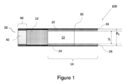
エアロゾル発生物品は、エアロゾル発生基体(12)と、エアロゾル発生基体の下流端からエアロゾル発生物品の下流端まで延在する下流セクション(14)と、を備える。エアロゾル発生物品は、エアロゾル発生基体の上流端からエアロゾル発生物品の下流端まで延びる上流セクション(40)をさらに備える。上流セクションの引き出し抵抗と下流セクションの引き出し抵抗の比は、1より大きく、上流セクションの引き出し抵抗は、150mmH2O以下である。【選択図】図1The aerosol-generating article includes an aerosol-generating substrate (12) and a downstream section (14) extending from the downstream end of the aerosol-generating substrate to the downstream end of the aerosol-generating article. The aerosol generating article further comprises an upstream section (40) extending from the upstream end of the aerosol generating substrate to the downstream end of the aerosol generating article. The ratio of the upstream section withdrawal resistance to the downstream section withdrawal resistance is greater than 1, and the upstream section withdrawal resistance is less than or equal to 150 mmH2O. [Selection diagram] Figure 1
Description
本発明は、エアロゾル発生基体を含み、かつ加熱に伴い吸入可能なエアロゾルを生成するように適合された、エアロゾル発生物品に関する。 The present invention relates to an aerosol-generating article comprising an aerosol-generating substrate and adapted to generate an inhalable aerosol upon heating.
タバコ含有基体などのエアロゾル発生基体が燃焼されるのではなく加熱されるエアロゾル発生物品は、当技術分野で公知である。典型的に、こうした加熱式喫煙物品においてエアロゾルは、熱源からの熱を、物理的に分離されたエアロゾル発生基体または材料に伝達することによって発生され、このエアロゾル発生基体または材料は熱源に接触して、または熱源内に、または熱源の周囲に、または熱源の下流に位置してもよい。エアロゾル発生物品の使用中、揮発性化合物は、熱源からの熱伝達によってエアロゾル発生基体から放出され、エアロゾル発生物品を通して引き出された空気中に同伴される。放出された化合物が冷却されると凝縮してエアロゾルを形成する。 Aerosol-generating articles in which an aerosol-generating substrate, such as a tobacco-containing substrate, is heated rather than combusted are known in the art. Typically, in such heated smoking articles, an aerosol is generated by transferring heat from a heat source to a physically separated aerosol-generating substrate or material that is in contact with the heat source. , or within, around, or downstream of the heat source. During use of the aerosol-generating article, volatile compounds are released from the aerosol-generating substrate by heat transfer from a heat source and entrained into the air drawn through the aerosol-generating article. When the released compounds cool, they condense to form an aerosol.
数多くの先行技術文書は、エアロゾル発生物品を消費するためのエアロゾル発生装置を開示している。こうした装置としては、例えばエアロゾル発生装置の一つ以上の電気ヒーター要素から加熱式エアロゾル発生物品のエアロゾル発生基体への熱伝達によってエアロゾルが発生される、電気加熱式のエアロゾル発生装置が挙げられる。例えば、エアロゾル発生基体に挿入されるように適合された内部ヒーターブレードを含む、電気加熱式のエアロゾル発生装置が提案されている。代替として、エアロゾル発生基体と、エアロゾル発生基体内に配置されたサセプタと、を含む、誘導性発熱性エアロゾル発生物品が、WO2015/176898によって提案されている。別の代替は、WO2020/115151に記載されており、これは、エアロゾル発生物品の外面の周りに配置される一つ以上の発熱体を備える外部加熱システムと組み合わせて使用される一つまたは複数エアロゾル発生物品を開示する。 Numerous prior art documents disclose aerosol generating devices for consuming aerosol generating articles. Such devices include, for example, electrically heated aerosol generating devices in which the aerosol is generated by heat transfer from one or more electric heater elements of the aerosol generating device to an aerosol generating substrate of a heated aerosol generating article. For example, electrically heated aerosol generation devices have been proposed that include internal heater blades adapted to be inserted into an aerosol generation substrate. Alternatively, an inductively exothermic aerosol-generating article comprising an aerosol-generating substrate and a susceptor disposed within the aerosol-generating substrate is proposed by WO2015/176898. Another alternative is described in WO 2020/115151, which describes one or more aerosol generators used in combination with an external heating system comprising one or more heating elements arranged around the outer surface of the aerosol-generating article. Disclose generated items.
タバコ含有基体が燃焼されるのではなく加熱されるエアロゾル発生物品は、従来の喫煙物品とは遭遇しなかったいくつかの課題を呈する。第一に、タバコ含有基体は、典型的には、従来のタバコの燃焼前部が到達する温度と比較して、著しく低い温度まで加熱される。これは、タバコ含有基体からのニコチン放出および消費者へのニコチン送達に影響を及ぼす可能性がある。同時に、ニコチン送達を促進する試みで加熱温度が上昇する場合、生成されるエアロゾルは、典型的には、消費者に到達する前に、より広範囲かつより迅速に冷却される必要がある。しかしながら、タバコの口側端部に高濾過効率セグメントを提供するなど、従来の喫煙物品において主流煙を冷却するために一般的に使用された技術的解決策は、タバコ含有基体がニコチン送達を減少させ得るため、燃焼されるよりもむしろ加熱されるエアロゾル発生物品において望ましくない効果を有し得る。 Aerosol-generating articles in which the tobacco-containing substrate is heated rather than combusted present several challenges not encountered with conventional smoking articles. First, the tobacco-containing substrate is typically heated to significantly lower temperatures compared to the temperatures reached by the combustion front of conventional tobacco. This can affect nicotine release from the tobacco-containing substrate and nicotine delivery to the consumer. At the same time, when heating temperatures are increased in an attempt to enhance nicotine delivery, the aerosol produced typically needs to be cooled more extensively and more quickly before reaching the consumer. However, technological solutions commonly used to cool mainstream smoke in conventional smoking articles, such as providing a high filtration efficiency segment at the mouth end of the cigarette, reduce nicotine delivery in tobacco-containing substrates. This can have undesirable effects in aerosol-generating articles that are heated rather than burned.
エアロゾルを発生させるためにエアロゾル発生基体の燃焼ではなく、特に加熱に関連する課題のうちの一つまたは複数に対処するために、多くのエアロゾル発生物品が提案されており、複数の要素が、例えば長手方向に整列して、エアロゾル発生基体を備えるエアロゾル発生要素と組み合わされる。一例として、エアロゾル発生要素は、物品に改善された構造強度を付与する支持要素、エアロゾルの温度を下げるように構成されたエアロゾル冷却要素、低濾過マウスピース要素等と組み合わされている。 A number of aerosol-generating articles have been proposed to address one or more of the challenges particularly associated with heating, rather than burning, an aerosol-generating substrate to generate an aerosol, and where multiple elements are involved, e.g. It is assembled in longitudinal alignment with an aerosol-generating element comprising an aerosol-generating substrate. By way of example, the aerosol generating element is combined with a support element that provides improved structural strength to the article, an aerosol cooling element configured to reduce the temperature of the aerosol, a low filtration mouthpiece element, etc.
一般的に、使いやすく、実用性が向上し、より環境に優しいエアロゾル発生物品が必要とされている。さらに、製造がより容易であり、生産チェーン全体をより持続可能で費用対効果が高いものにするエアロゾル発生物品を提供することが望ましいであろう。また、外部加熱システムと組み合わせて使用するのに特に好適なエアロゾル発生物品、特にエアロゾル発生およびエアロゾル形成体送達を改良したエアロゾル発生物品が必要である。 There is a general need for aerosol-generating articles that are easier to use, more practical, and more environmentally friendly. Furthermore, it would be desirable to provide an aerosol-generating article that is easier to manufacture and makes the entire production chain more sustainable and cost-effective. There is also a need for aerosol-generating articles that are particularly suitable for use in conjunction with external heating systems, particularly aerosol-generating articles that have improved aerosol generation and aerosol former delivery.
したがって、上記の必要性のうちの少なくとも一つを満たすように構成された、新規で改良されたエアロゾル発生物品を提供することが望ましいであろう。さらに、効率的かつ高速で製造でき、好ましくは製品間のRTD変動が十分に低いエアロゾル発生物品を提供することが望ましいであろう。 Accordingly, it would be desirable to provide new and improved aerosol generating articles configured to meet at least one of the above needs. Additionally, it would be desirable to provide an aerosol-generating article that can be manufactured efficiently and quickly, and preferably with sufficiently low RTD variation from product to product.
本開示は、加熱に伴い吸入可能なエアロゾルを生成するためのエアロゾル発生物品に関する。エアロゾル発生物品は、エアロゾル発生基体を備えてもよい。エアロゾル発生物品は、エアロゾル発生基体の下流端からエアロゾル発生物品の下流端まで延びる下流セクションを備え得る。エアロゾル発生物品は、エアロゾル発生基体の上流端からエアロゾル発生物品の下流端まで延びる上流セクションを備え得る。上流セクションの引き出し抵抗と下流セクションの引き出し抵抗の比は1より大きくてもよい。 The present disclosure relates to an aerosol-generating article for producing an inhalable aerosol upon heating. The aerosol generating article may include an aerosol generating substrate. The aerosol-generating article may include a downstream section extending from the downstream end of the aerosol-generating substrate to the downstream end of the aerosol-generating article. The aerosol generating article may include an upstream section extending from the upstream end of the aerosol generating substrate to the downstream end of the aerosol generating article. The ratio of the withdrawal resistance of the upstream section to the withdrawal resistance of the downstream section may be greater than 1.
本発明によれば、加熱時に吸入可能なエアロゾルを生成するためのエアロゾル発生物品が提供され、エアロゾル発生物品は、エアロゾル発生基体、エアロゾル発生基体の下流端からエアロゾル発生物品の下流端に延在する下流セクション、およびエアロゾル発生基体の上流端からエアロゾル発生物品の上流端に延在する上流セクションを含む。上流セクションの引き出し抵抗と下流セクションの引き出し抵抗の比は1より大きい。 According to the present invention, an aerosol-generating article for producing an inhalable aerosol upon heating is provided, the aerosol-generating article comprising an aerosol-generating substrate, extending from a downstream end of the aerosol-generating substrate to a downstream end of the aerosol-generating article. a downstream section, and an upstream section extending from the upstream end of the aerosol generating substrate to the upstream end of the aerosol generating article. The ratio of the withdrawal resistance of the upstream section to the withdrawal resistance of the downstream section is greater than 1.
本発明の実施形態では、上流セクションのRTDは、下流セクションのRTDよりも高い。下流セクションが比較的低いRTD、例えば約10mmH2O未満のRTDを有する場合、比較的高いRTDを有する上流要素を設けることは、有利なことに、エアロゾル発生基体の下流のフィルターなどの高いRTD要素を必要とすることなく、許容可能な全体的なRTDを提供することができる。これは、エアロゾル発生物品の全体的なRTDを許容不能なほどに低下させることなく、ユーザーへのエアロゾルの送達を最大化し得る。使用中、空気は、上流セクションの上流端を通ってエアロゾル発生物品に入り、上流セクションを通過して、エアロゾル発生基体内に入る。そして、空気は下流セクション内に入って通過し、その後下流セクションの下流端から出る。 In embodiments of the invention, the RTD of the upstream section is higher than the RTD of the downstream section. If the downstream section has a relatively low RTD, e.g. an RTD of less than about 10 mm H2O , it is advantageous to provide an upstream element with a relatively high RTD, such as a high RTD element, such as a filter downstream of the aerosol-generating substrate. can provide an acceptable overall RTD without the need for This may maximize delivery of aerosol to the user without unacceptably lowering the overall RTD of the aerosol-generating article. In use, air enters the aerosol-generating article through the upstream end of the upstream section, passes through the upstream section, and into the aerosol-generating substrate. The air then enters and passes through the downstream section and then exits from the downstream end of the downstream section.
上流セクションのRTDが、エアロゾル発生物品全体のRTDの大部分を占めてもよい。 The RTD of the upstream section may account for the majority of the RTD of the entire aerosol generating article.
本発明によると、加熱に伴い吸入可能なエアロゾルを発生させるためのエアロゾル発生物品が提供されている。エアロゾル発生物品は、エアロゾル発生基体を備える要素を備える。 According to the present invention, an aerosol-generating article for generating an inhalable aerosol upon heating is provided. The aerosol-generating article includes an element that includes an aerosol-generating substrate.
本明細書で使用する用語「エアロゾル発生物品」は、エアロゾル発生基体を加熱して吸入可能なエアロゾルを生成して消費者に送達する物品を示す。本明細書で使用される「エアロゾル発生基体」という用語は、加熱に伴い揮発性化合物を放出してエアロゾルを発生する能力を有する基体を意味する。 As used herein, the term "aerosol-generating article" refers to an article that heats an aerosol-generating substrate to produce an inhalable aerosol for delivery to a consumer. As used herein, the term "aerosol-generating substrate" refers to a substrate that has the ability to generate an aerosol by releasing volatile compounds upon heating.
従来の紙巻たばこは、ユーザーが紙巻たばこの一方の端に炎を当て、もう一方の端を通して空気を引き出す時に点火される。炎と、紙巻タバコを通して引き出された空気中の酸素とによってもたらされた局在化した熱は、紙巻タバコの端を点火させ、その結果生じる燃焼は吸入可能な煙を発生する。これに反して、加熱式エアロゾル発生物品において、エアロゾルは風味発生基体(タバコなど)を加熱することによって発生される。公知の加熱式エアロゾル発生物品としては、例えば電気加熱式エアロゾル発生物品と、可燃性燃料要素または熱源から、物理的に分離されたエアロゾル形成材料への熱伝達によってエアロゾルが発生するエアロゾル発生物品とが挙げられる。例えば、本発明によるエアロゾル発生物品は、エアロゾル発生基体のロッドの中に挿入されるように適合されている内部ヒーターブレードを有する電気加熱式のエアロゾル発生装置を備えるエアロゾル発生システムにおいて特定の用途がある。このタイプのエアロゾル発生物品は、先行技術、例えばEP0822670に記載されている。 Traditional cigarettes are lit when a user applies a flame to one end of the cigarette and draws air through the other end. The localized heat provided by the flame and the oxygen in the air drawn through the cigarette ignites the end of the cigarette and the resulting combustion produces inhalable smoke. In contrast, in heated aerosol-generating articles, the aerosol is generated by heating a flavor-generating substrate (such as tobacco). Known heated aerosol generating articles include, for example, electrically heated aerosol generating articles and aerosol generating articles in which an aerosol is generated by heat transfer from a combustible fuel element or heat source to a physically separated aerosol forming material. Can be mentioned. For example, an aerosol-generating article according to the invention has particular application in an aerosol-generating system comprising an electrically heated aerosol-generating device having an internal heater blade adapted to be inserted into a rod of an aerosol-generating substrate. . Aerosol-generating articles of this type are described in the prior art, for example in EP0822670.
本明細書で使用される場合、「エアロゾル発生装置」という用語は、エアロゾル発生物品のエアロゾル発生基体と相互作用してエアロゾルを発生するヒーター要素を備える装置を指す。 As used herein, the term "aerosol generating device" refers to a device that includes a heater element that interacts with an aerosol generating substrate of an aerosol generating article to generate an aerosol.
エアロゾル発生要素は、エアロゾル発生基体を備えるか、またはそれで作られるロッドの形態であってもよい。本発明に関連して本明細書で使用される「ロッド」という用語は、実質的に円形、長円形または楕円形の断面の一般的に円柱状の要素を示すために使用される。 The aerosol generating element may be in the form of a rod comprising or made of an aerosol generating substrate. The term "rod" as used herein in connection with the present invention is used to denote a generally cylindrical element of substantially circular, oval or elliptical cross section.
本明細書で使用される「長手方向」という用語は、エアロゾル発生物品の上流端と下流端の間に延びる、エアロゾル発生物品の主要長手方向軸に対応する方向を指す。本明細書で使用される「上流」および「下流」という用語は、使用中にエアロゾル発生物品を通してエアロゾルが搬送される方向に関してエアロゾル発生物品の要素(または要素の部分)の相対的な位置を説明する。 As used herein, the term "longitudinal" refers to a direction corresponding to the main longitudinal axis of the aerosol-generating article, extending between the upstream and downstream ends of the aerosol-generating article. The terms "upstream" and "downstream" as used herein describe the relative position of an element (or portion of an element) of an aerosol-generating article with respect to the direction in which aerosol is conveyed through the aerosol-generating article during use. do.
使用中、空気はエアロゾル発生物品を通して長手方向に引き出される。「横断方向」という用語は、長手方向軸に対して直角をなす方向を指す。エアロゾル発生物品またはエアロゾル発生物品の構成要素の「断面」への任意の言及は、別途記載のない限り、横断断面を指す。 During use, air is drawn longitudinally through the aerosol generating article. The term "transverse" refers to a direction perpendicular to the longitudinal axis. Any reference to a "cross-section" of an aerosol-generating article or a component of an aerosol-generating article refers to a cross-section, unless otherwise specified.
「長さ」という用語は、長手方向におけるエアロゾル発生物品の構成要素の寸法を意味する。例えば、長手方向におけるロッドまたは細長い管状要素の寸法を意味するために使用されてもよい。 The term "length" refers to the dimension of a component of an aerosol generating article in the longitudinal direction. For example, it may be used to mean the dimension of a rod or elongated tubular element in the longitudinal direction.
エアロゾル発生物品は、エアロゾル発生基体の下流の位置に下流セクションをさらに備える。本発明のエアロゾル発生物品の異なる実施形態の以下の説明から明らかになるように、下流セクションは、一つ以上の下流要素を含み得る。 The aerosol generating article further comprises a downstream section at a location downstream of the aerosol generating substrate. As will become apparent from the following description of different embodiments of the aerosol generating article of the present invention, the downstream section may include one or more downstream elements.
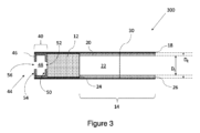
いくつかの実施形態では、下流セクションは、エアロゾル発生物品の口側端とエアロゾル発生要素との間の中空セクションを備えることができる。中空セクションは、中空の管状要素を備えてもよい。 In some embodiments, the downstream section can include a hollow section between the mouth end of the aerosol-generating article and the aerosol-generating element. The hollow section may comprise a hollow tubular element.
本明細書で使用する場合、用語「中空の管状要素」は、その長手方向軸に沿った空洞または気流通路を画成する一般的に細長い要素を示す。特に、「管状」という用語は以下において、実質的に円筒状の断面を有する、かつ管状要素の上流端と管状要素の下流端との間の途切れることのない流体連通を確立する少なくとも一つの気流導管を画定する、管状要素に関して使用される。しかし、当然のことながら、管状要素の代替の形状(例えば、代替の断面形状)が可能である場合がある。 As used herein, the term "hollow tubular element" refers to a generally elongate element that defines a cavity or airflow passageway along its longitudinal axis. In particular, the term "tubular" hereinafter refers to at least one air flow having a substantially cylindrical cross-section and establishing uninterrupted fluid communication between the upstream end of the tubular element and the downstream end of the tubular element. Used in connection with tubular elements that define conduits. However, it will be appreciated that alternative shapes of the tubular element (eg, alternative cross-sectional shapes) may be possible.
本発明の文脈において、中空の管状要素は、制限のない流路を提供する。これは、中空の管状要素が、無視できるレベルの引き出し抵抗(RTD)を提供することを意味する。用語「無視できるレベルのRTD」は、中空の管状要素の長さ10ミリメートル当たり1mmH2O未満のRTD、好ましくは中空の管状要素の長さ10ミリメートル当たり0.4mmH2O未満、より好ましくは中空の管状要素の長さ10ミリメートル当たり0.1mmH2O未満のRTDを表すために使用される。 In the context of the present invention, hollow tubular elements provide an unrestricted flow path. This means that the hollow tubular element provides a negligible level of resistance to withdrawal (RTD). The term "negligible RTD" means an RTD of less than 1 mm H2O per 10 mm of length of a hollow tubular element, preferably less than 0.4 mm H2O per 10 mm of length of a hollow tubular element, more preferably a hollow is used to express an RTD of less than 0.1 mm H 2 O per 10 mm of length of the tubular element.
したがって、流れチャネルは、長手方向の空気の流れを妨害するであろういかなる構成要素も含むべきではない。好ましくは、流れチャネルは、実質的に空である。 Therefore, the flow channels should not include any components that would obstruct longitudinal air flow. Preferably the flow channel is substantially empty.
エアロゾル発生物品は、下流セクションに沿った位置に第一の通気ゾーンを備え得る。より詳細には、エアロゾル発生物品は、中空の管状要素に沿った位置に第一の通気ゾーンを備え得る。このように、中空の管状要素によって内部に画成された流路と外部環境との間に流体連通が確立される。 The aerosol generating article may include a first ventilation zone at a location along the downstream section. More particularly, the aerosol generating article may include a first ventilation zone located along the hollow tubular element. In this way, fluid communication is established between the flow path defined therein by the hollow tubular element and the external environment.
エアロゾル発生物品は、エアロゾル発生基体のロッドの上流の位置に上流セクションをさらに備える。上流セクションは、一つ以上の上流要素を備え得る。いくつかの実施形態では、上流セクションは、エアロゾル発生要素のすぐ上流に配置される上流要素を備えることができる。 The aerosol generating article further comprises an upstream section at a location upstream of the rod of the aerosol generating substrate. The upstream section may include one or more upstream elements. In some embodiments, the upstream section can include an upstream element positioned immediately upstream of the aerosol generating element.
簡潔に上述されるように、本発明に従うエアロゾル発生物品は、エアロゾル発生基体を備える。 As briefly described above, an aerosol-generating article according to the present invention comprises an aerosol-generating substrate.
いくつかの実施形態では、エアロゾル発生要素は、エアロゾル発生基体を備えるロッドの形態で設けられることができる。一例として、エアロゾル発生要素は、ラッパーによって取り囲まれたエアロゾル発生基体のロッドを備えてもよい。 In some embodiments, the aerosol-generating element can be provided in the form of a rod that includes an aerosol-generating substrate. As an example, the aerosol generating element may comprise a rod of aerosol generating substrate surrounded by a wrapper.
エアロゾル発生基体は、少なくとも約5ミリメートルの長さを有することができる。エアロゾル発生基体は、少なくとも約7ミリメートルの長さを有することが好ましい。エアロゾル発生基体は、少なくとも約10ミリメートルの長さを有することがより好ましい。特に好ましい実施形態では、エアロゾル発生基体は、少なくとも約12ミリメートルの長さを有する。 The aerosol generating substrate can have a length of at least about 5 millimeters. Preferably, the aerosol generating substrate has a length of at least about 7 millimeters. More preferably, the aerosol generating substrate has a length of at least about 10 millimeters. In particularly preferred embodiments, the aerosol generating substrate has a length of at least about 12 millimeters.
エアロゾル発生基体は、最大で約80ミリメートルの長さを有することができる。エアロゾル発生基体は、約65ミリメートル以下の長さを有することが好ましい。エアロゾル発生基体は、約60ミリメートル以下の長さを有することがより好ましい。エアロゾル発生基体は、約55ミリメートル以下の長さを有することがさらにより好ましい。 The aerosol generating substrate can have a length of up to about 80 millimeters. Preferably, the aerosol generating substrate has a length of about 65 millimeters or less. More preferably, the aerosol generating substrate has a length of about 60 millimeters or less. Even more preferably, the aerosol generating substrate has a length of about 55 millimeters or less.
特に好ましい実施形態では、エアロゾル発生基体は、約50ミリメートル以下、より好ましくは約35ミリメートル以下、さらにより好ましくは約25ミリメートル以下の長さを有する。特に好ましい実施形態では、エアロゾル発生基体は、約20ミリメートル以下、または約15ミリメートル以下の長さを有する。 In particularly preferred embodiments, the aerosol generating substrate has a length of about 50 millimeters or less, more preferably about 35 millimeters or less, and even more preferably about 25 millimeters or less. In particularly preferred embodiments, the aerosol generating substrate has a length of about 20 millimeters or less, or about 15 millimeters or less.
いくつかの実施形態では、エアロゾル発生基体は、約5ミリメートル~約60ミリメートルの長さを有し、約6ミリメートル~約60ミリメートルが好ましく、約7ミリメートル~約60ミリメートルがより好ましく、約10ミリメートル~約60ミリメートルがさらにより好ましく、約12ミリメートル~約60ミリメートルが最も好ましい。別の実施形態では、エアロゾル発生基体は、約5ミリメートル~約55ミリメートルの長さを有し、約6ミリメートル~約55ミリメートルが好ましく、約7ミリメートル~約55ミリメートルがより好ましく、約10ミリメートル~約55ミリメートルがさらにより好ましく、約12ミリメートル~約55ミリメートルが最も好ましい。別の実施形態では、エアロゾル発生基体は、約5ミリメートル~約50ミリメートルの長さを有し、約6ミリメートル~約50ミリメートルが好ましく、約7ミリメートル~約50ミリメートルがより好ましく、約10ミリメートル~約50ミリメートルがさらにより好ましく、約12ミリメートル~約50ミリメートルが最も好ましい。 In some embodiments, the aerosol-generating substrate has a length of about 5 mm to about 60 mm, preferably about 6 mm to about 60 mm, more preferably about 7 mm to about 60 mm, and more preferably about 10 mm. Even more preferred is from about 60 millimeters, and most preferred is from about 12 millimeters to about 60 millimeters. In another embodiment, the aerosol-generating substrate has a length from about 5 mm to about 55 mm, preferably from about 6 mm to about 55 mm, more preferably from about 7 mm to about 55 mm, and from about 10 mm to about 55 mm. Even more preferred is about 55 millimeters, and most preferred is from about 12 millimeters to about 55 millimeters. In another embodiment, the aerosol-generating substrate has a length of about 5 millimeters to about 50 millimeters, preferably about 6 millimeters to about 50 millimeters, more preferably about 7 millimeters to about 50 millimeters, and about 10 millimeters to about 50 millimeters. Even more preferably about 50 millimeters, and most preferably from about 12 millimeters to about 50 millimeters.
いくつかの特に好ましい実施形態では、エアロゾル発生基体は、約5ミリメートル~約30ミリメートルの長さを有し、約6ミリメートル~約30ミリメートルが好ましく、約7ミリメートル~約30ミリメートルがより好ましく、約10ミリメートル~約30ミリメートルがさらにより好ましい。別の特に好ましい実施形態では、エアロゾル発生基体は、約5ミリメートル~約20ミリメートルの長さを有し、約6ミリメートル~約20ミリメートルが好ましく、約7ミリメートル~約20ミリメートルがより好ましく、約10ミリメートル~約20ミリメートルがさらにより好ましい。別の特に好ましい実施形態では、エアロゾル発生基体は、約5ミリメートル~約15ミリメートルの長さを有し、約7ミリメートル~約20ミリメートルが好ましく、約9ミリメートル~約16ミリメートルがより好ましく、約10ミリメートル~約15ミリメートルがさらにより好ましい。 In some particularly preferred embodiments, the aerosol-generating substrate has a length of about 5 millimeters to about 30 millimeters, preferably about 6 millimeters to about 30 millimeters, more preferably about 7 millimeters to about 30 millimeters, and about Even more preferred is from 10 millimeters to about 30 millimeters. In another particularly preferred embodiment, the aerosol generating substrate has a length of about 5 mm to about 20 mm, preferably about 6 mm to about 20 mm, more preferably about 7 mm to about 20 mm, and more preferably about 10 mm to about 20 mm. Even more preferred are millimeters to about 20 millimeters. In another particularly preferred embodiment, the aerosol generating substrate has a length of about 5 millimeters to about 15 millimeters, preferably about 7 millimeters to about 20 millimeters, more preferably about 9 millimeters to about 16 millimeters, and more preferably about 10 millimeters to about 10 millimeters. Even more preferred are millimeters to about 15 millimeters.
エアロゾル発生基体は、エアロゾル発生物品の外径にほぼ等しい外径を有することが好ましい。 Preferably, the aerosol-generating substrate has an outer diameter approximately equal to the outer diameter of the aerosol-generating article.
好ましくは、エアロゾル発生基体は、少なくとも約3ミリメートル、少なくとも約4ミリメートルまたは少なくとも約5ミリメートルの外径を有する。エアロゾル発生基体は、少なくとも約6ミリメートルの外径を有することがより好ましい。エアロゾル発生基体は、少なくとも約7ミリメートルの外径を有することが更により好ましい。 Preferably, the aerosol generating substrate has an outer diameter of at least about 3 millimeters, at least about 4 millimeters or at least about 5 millimeters. More preferably, the aerosol generating substrate has an outer diameter of at least about 6 millimeters. Even more preferably, the aerosol generating substrate has an outer diameter of at least about 7 millimeters.
エアロゾル発生基体は、約12ミリメートル以下の外径を有することが好ましい。エアロゾル発生基体は、約10ミリメートル以下の外径を有することがより好ましい。エアロゾル発生基体は、約8ミリメートル以下の外径を有することが更により好ましい。 Preferably, the aerosol generating substrate has an outer diameter of about 12 millimeters or less. More preferably, the aerosol generating substrate has an outer diameter of about 10 millimeters or less. Even more preferably, the aerosol generating substrate has an outer diameter of about 8 millimeters or less.
一般的に、エアロゾル発生基体の直径が小さいほど、エアロゾル発生要素のコア温度を上昇させるのに必要な温度が低くなり、十分な量の気化種がエアロゾル発生基体から放出されて、所望の量のエアロゾルを形成する。同時に、理論に拘束されることを意図するものではないが、エアロゾル発生基体の直径が小さいほど、エアロゾル発生物品に供給される熱が、エアロゾル形成基体の全容量により速く浸透することが可能になることは理解される。それにもかかわらず、エアロゾル発生基体の直径が小さすぎる場合、エアロゾル発生基体の容量対表面積比は、利用可能なエアロゾル形成基体の量が減少するにつれて、好ましくなくなる。 Generally, the smaller the diameter of the aerosol-generating substrate, the lower the temperature required to raise the core temperature of the aerosol-generating element and ensure that a sufficient amount of vaporized species is released from the aerosol-generating substrate to produce the desired amount. Forms an aerosol. At the same time, without intending to be bound by theory, a smaller diameter of the aerosol-generating substrate allows the heat supplied to the aerosol-generating article to penetrate faster into the entire volume of the aerosol-forming substrate. That is understood. Nevertheless, if the diameter of the aerosol-generating substrate is too small, the volume to surface area ratio of the aerosol-generating substrate becomes unfavorable as the amount of available aerosol-forming substrate decreases.
本明細書に記載の範囲内に入るエアロゾル発生基体の直径は、エネルギー消費とエアロゾル送達との間のバランスという点では、特に有利である。この利点は、本明細書に記載の直径を有するエアロゾル発生基体を備えるエアロゾル発生物品が、エアロゾル発生物品の周辺の周りに配置される外部ヒーターと組み合わせて使用される場合、特に実感される。このような動作条件下で、十分に高い温度を、エアロゾル発生基体のコアで、一般的には、物品のコアで達成するのに必要な熱エネルギーが少ないことが観察された。これにより、より低い温度で動作する場合、エアロゾル発生基体のコアにおける所望の目標温度は、望ましく短縮された時間枠内で、かつより低いエネルギー消費によって達成されることができる。 Aerosol-generating substrate diameters falling within the ranges described herein are particularly advantageous in terms of the balance between energy consumption and aerosol delivery. This advantage is particularly realized when an aerosol generating article comprising an aerosol generating substrate having a diameter as described herein is used in combination with an external heater positioned around the periphery of the aerosol generating article. Under such operating conditions, it has been observed that less thermal energy is required to achieve a sufficiently high temperature at the core of the aerosol-generating substrate, and generally at the core of the article. Thereby, when operating at lower temperatures, the desired target temperature in the core of the aerosol-generating substrate can be achieved within a desirably shortened time frame and with lower energy consumption.
いくつかの実施形態では、エアロゾル発生基体のロッドは、約5ミリメートル~約12ミリメートル、好ましくは約6ミリメートル~約12ミリメートル、より好ましくは約7ミリメートル~約12ミリメートルの外径を有する。他の実施形態では、エアロゾル発生基体は、約5ミリメートル~約12ミリメートル、好ましくは約6ミリメートル~約10ミリメートル、より好ましくは約7ミリメートル~約10ミリメートルの外径を有する。更なる実施形態では、エアロゾル発生基体は、約5ミリメートル~約8ミリメートル、好ましくは約6ミリメートル~約8ミリメートル、より好ましくは約7ミリメートル~約8ミリメートルの外径を有する。 In some embodiments, the rod of the aerosol generating substrate has an outer diameter of about 5 mm to about 12 mm, preferably about 6 mm to about 12 mm, more preferably about 7 mm to about 12 mm. In other embodiments, the aerosol-generating substrate has an outer diameter of about 5 mm to about 12 mm, preferably about 6 mm to about 10 mm, more preferably about 7 mm to about 10 mm. In further embodiments, the aerosol generating substrate has an outer diameter of about 5 mm to about 8 mm, preferably about 6 mm to about 8 mm, more preferably about 7 mm to about 8 mm.
エアロゾル発生基体は、3.7ミリメートル~9ミリメートル、または5.7ミリメートル~7.9ミリメートルの外径を有し得る。 The aerosol generating substrate may have an outer diameter of 3.7 mm to 9 mm, or 5.7 mm to 7.9 mm.
特に好ましい実施形態では、エアロゾル発生基体は、約7.5ミリメートル未満の外径を有する。一例として、エアロゾル発生基体は、約7.2ミリメートルの外径を有し得る。 In particularly preferred embodiments, the aerosol generating substrate has an outer diameter of less than about 7.5 millimeters. As an example, the aerosol generating substrate may have an outer diameter of about 7.2 millimeters.
エアロゾル発生要素の長さの直径に対する比は、少なくとも約0.5とすることができる。エアロゾル発生要素の長さの直径に対する比は、少なくとも約0.75であることが好ましい。エアロゾル発生要素の長さの直径に対する比は、少なくとも約1.0であることがより好ましい。エアロゾル発生要素の長さの直径に対する比は、少なくとも約1.25であることがさらにより好ましい。 The length to diameter ratio of the aerosol generating element can be at least about 0.5. Preferably, the length to diameter ratio of the aerosol generating element is at least about 0.75. More preferably, the length to diameter ratio of the aerosol generating element is at least about 1.0. Even more preferably, the length to diameter ratio of the aerosol generating element is at least about 1.25.
エアロゾル発生要素の長さの直径に対する比は、約3.0以下とすることができる。エアロゾル発生要素の長さの直径に対する比は、約2.75以下であることが好ましい。エアロゾル発生要素の長さの直径に対する比は、約2.5以下であることがより好ましい。エアロゾル発生要素の長さの直径に対する比は、約2.25以下であることがさらにより好ましい。 The length to diameter ratio of the aerosol generating element can be about 3.0 or less. Preferably, the length to diameter ratio of the aerosol generating element is about 2.75 or less. More preferably, the length to diameter ratio of the aerosol generating element is about 2.5 or less. Even more preferably, the length to diameter ratio of the aerosol generating element is about 2.25 or less.
いくつかの実施形態では、エアロゾル発生要素の長さの直径に対する比は、約0.5~約3.0とすることができる。エアロゾル発生要素の長さの直径に対する比は、約0.75~約3.0であることが好ましい。エアロゾル発生要素の長さの直径に対する比は、約1.0~約3.0であることがより好ましい。エアロゾル発生要素の長さの直径に対する比は、約1.25~約3.0であることがさらにより好ましい。 In some embodiments, the length to diameter ratio of the aerosol generating element can be from about 0.5 to about 3.0. Preferably, the length to diameter ratio of the aerosol generating element is from about 0.75 to about 3.0. More preferably, the length to diameter ratio of the aerosol generating element is from about 1.0 to about 3.0. Even more preferably, the length to diameter ratio of the aerosol generating element is from about 1.25 to about 3.0.
別の実施形態では、エアロゾル発生要素の長さの直径に対する比は、約0.5~約2.75とすることができる。エアロゾル発生要素の長さの直径に対する比は、約0.75~約2.75であることが好ましい。エアロゾル発生要素の長さの直径に対する比は、約1.0~約2.75であることがより好ましい。エアロゾル発生要素の長さの直径に対する比は、約1.25~約2.75であることがさらにより好ましい。 In another embodiment, the length to diameter ratio of the aerosol generating element can be from about 0.5 to about 2.75. Preferably, the length to diameter ratio of the aerosol generating element is from about 0.75 to about 2.75. More preferably, the length to diameter ratio of the aerosol generating element is from about 1.0 to about 2.75. Even more preferably, the length to diameter ratio of the aerosol generating element is from about 1.25 to about 2.75.
別の実施形態では、エアロゾル発生要素の長さの直径に対する比は、約0.5~約2.5とすることができる。エアロゾル発生要素の長さの直径に対する比は、約0.75~約2.5であることが好ましい。エアロゾル発生要素の長さの直径に対する比は、約1.0~約2.5であることがより好ましい。エアロゾル発生要素の長さの直径に対する比は、約1.25~約2.5であることがさらにより好ましい。 In another embodiment, the length to diameter ratio of the aerosol generating element can be from about 0.5 to about 2.5. Preferably, the length to diameter ratio of the aerosol generating element is from about 0.75 to about 2.5. More preferably, the length to diameter ratio of the aerosol generating element is from about 1.0 to about 2.5. Even more preferably, the length to diameter ratio of the aerosol generating element is from about 1.25 to about 2.5.
さらに別の実施形態では、エアロゾル発生要素の長さの直径に対する比は、約0.5~約2.25とすることができる。エアロゾル発生要素の長さの直径に対する比は、約0.75~約2.25であることが好ましい。エアロゾル発生要素の長さの直径に対する比は、約1.0~約2.25であることがより好ましい。エアロゾル発生要素の長さの直径に対する比は、約1.25~約2.25であることがさらにより好ましい。 In yet another embodiment, the length to diameter ratio of the aerosol generating element can be from about 0.5 to about 2.25. Preferably, the length to diameter ratio of the aerosol generating element is from about 0.75 to about 2.25. More preferably, the length to diameter ratio of the aerosol generating element is from about 1.0 to about 2.25. Even more preferably, the length to diameter ratio of the aerosol generating element is from about 1.25 to about 2.25.
特に好ましい実施形態では、エアロゾル発生要素の長さの直径に対する比は、少なくとも約1.3とすることができ、約1.4がより好ましく、約1.5がさらにより好ましい。 In particularly preferred embodiments, the length to diameter ratio of the aerosol generating element can be at least about 1.3, more preferably about 1.4, and even more preferably about 1.5.
特に好ましい実施形態では、エアロゾル発生要素の長さの直径に対する比は、約2.0以下とすることができ、約1.9以下がより好ましく、約1.8以下がさらにより好ましい。 In particularly preferred embodiments, the length to diameter ratio of the aerosol generating element can be about 2.0 or less, more preferably about 1.9 or less, and even more preferably about 1.8 or less.
いくつかの実施形態では、エアロゾル発生要素の長さの直径に対する比は、約1.3~約2.0であることが好ましく、約1.4~約2.0がより好ましく、約1.5~約2.0がさらにより好ましい。別の実施形態では、エアロゾル発生要素の長さの直径に対する比は、約1.3~約1.9であることが好ましく、約1.4~約1.7がより好ましく、約1.5~約1.9がさらにより好ましい。別の実施形態では、エアロゾル発生要素の長さの直径に対する比は、約1.3~約1.8であることが好ましく、約1.4~約1.8がより好ましく、約1.5~約1.8がさらにより好ましい。 In some embodiments, the length to diameter ratio of the aerosol generating element is preferably from about 1.3 to about 2.0, more preferably from about 1.4 to about 2.0, and more preferably from about 1.3 to about 2.0. 5 to about 2.0 is even more preferred. In another embodiment, the length to diameter ratio of the aerosol generating element is preferably from about 1.3 to about 1.9, more preferably from about 1.4 to about 1.7, and more preferably from about 1.5 to about 1.9 is even more preferred. In another embodiment, the length to diameter ratio of the aerosol generating element is preferably from about 1.3 to about 1.8, more preferably from about 1.4 to about 1.8, and more preferably from about 1.5 to about 1.8 is even more preferred.
エアロゾル発生要素の長さとエアロゾル発生物品の全長との比は、少なくとも約0.10とすることができる。エアロゾル発生要素の長さとエアロゾル発生物品の全長との比は、少なくとも約0.15であることが好ましい。エアロゾル発生要素の長さとエアロゾル発生物品の全長との比は、少なくとも約0.20であることがより好ましい。エアロゾル発生要素の長さとエアロゾル発生物品の全長との比は、少なくとも約0.25であることがさらにより好ましい。 The ratio of the length of the aerosol generating element to the overall length of the aerosol generating article can be at least about 0.10. Preferably, the ratio of the length of the aerosol generating element to the overall length of the aerosol generating article is at least about 0.15. More preferably, the ratio of the length of the aerosol generating element to the overall length of the aerosol generating article is at least about 0.20. Even more preferably, the ratio of the length of the aerosol generating element to the overall length of the aerosol generating article is at least about 0.25.
通常、エアロゾル発生要素の長さとエアロゾル発生物品の全長との比は、約0.60以下とすることができる。エアロゾル発生要素の長さとエアロゾル発生物品の全長との比は、約0.50以下であることが好ましい。エアロゾル発生要素の長さとエアロゾル発生物品の全長との比は、約0.45以下であることがより好ましい。エアロゾル発生要素の長さとエアロゾル発生物品の全長との比は、約0.40以下であることがさらにより好ましい。特に好ましい実施形態では、エアロゾル発生要素の長さとエアロゾル発生物品の全長との比は、約0.35以下であり、約0.30以下が最も好ましい。 Typically, the ratio of the length of the aerosol generating element to the overall length of the aerosol generating article can be about 0.60 or less. Preferably, the ratio of the length of the aerosol generating element to the overall length of the aerosol generating article is about 0.50 or less. More preferably, the ratio of the length of the aerosol generating element to the total length of the aerosol generating article is about 0.45 or less. Even more preferably, the ratio of the length of the aerosol generating element to the overall length of the aerosol generating article is about 0.40 or less. In particularly preferred embodiments, the ratio of the length of the aerosol generating element to the overall length of the aerosol generating article is about 0.35 or less, most preferably about 0.30 or less.
いくつかの実施形態では、エアロゾル発生要素の長さとエアロゾル発生物品の全長との比は、約0.10~約0.45であり、約0.15~約0.45が好ましく、約0.20~約0.45がより好ましく、約0.25~約0.45がさらにより好ましい。別の実施形態では、エアロゾル発生要素の長さとエアロゾル発生物品の全長との比は、約0.10~約0.40であり、約0.15~約0.40が好ましく、約0.20~約0.40がより好ましく、約0.25~約0.40がさらにより好ましい。別の実施形態では、エアロゾル発生要素の長さとエアロゾル発生物品の全長との比は、約0.10~約0.35であり、約0.15~約0.35が好ましく、約0.20~約0.35がより好ましく、約0.25~約0.35がさらにより好ましい。さらに別の実施形態では、エアロゾル発生要素の長さとエアロゾル発生物品の全長との比は、約0.10~約0.30であり、約0.15~約0.30が好ましく、約0.20~約0.30がより好ましく、約0.25~約0.30がさらにより好ましい。 In some embodiments, the ratio of the length of the aerosol-generating element to the total length of the aerosol-generating article is about 0.10 to about 0.45, preferably about 0.15 to about 0.45, and about 0.15 to about 0.45, preferably about 0.15 to about 0.45. More preferably from 20 to about 0.45, and even more preferably from about 0.25 to about 0.45. In another embodiment, the ratio of the length of the aerosol-generating element to the total length of the aerosol-generating article is about 0.10 to about 0.40, preferably about 0.15 to about 0.40, and about 0.20. More preferably, from about 0.40 to about 0.40, and even more preferably from about 0.25 to about 0.40. In another embodiment, the ratio of the length of the aerosol-generating element to the total length of the aerosol-generating article is about 0.10 to about 0.35, preferably about 0.15 to about 0.35, and about 0.20. More preferably, from about 0.35 to about 0.35, and even more preferably from about 0.25 to about 0.35. In yet another embodiment, the ratio of the length of the aerosol-generating element to the overall length of the aerosol-generating article is about 0.10 to about 0.30, preferably about 0.15 to about 0.30, and about 0.10 to about 0.30. More preferably from 20 to about 0.30, and even more preferably from about 0.25 to about 0.30.
エアロゾル発生要素は、ロッドの長さに沿って実質的に均一な断面を有するエアロゾル発生基体のロッドを備えることが好ましい。エアロゾル発生基体のロッドは、実質的に円形の断面を有することが特に好ましい。 Preferably, the aerosol-generating element comprises a rod of aerosol-generating substrate having a substantially uniform cross-section along the length of the rod. It is particularly preferred that the rod of the aerosol-generating substrate has a substantially circular cross-section.
以下でより詳細に説明するように、本発明によるエアロゾル発生物品は、中空の管状要素を備える下流セクションを備える。本発明によるエアロゾル発生物品では、エアロゾル発生要素の長さと中空の管状要素の長さとの比は、約0.66以下とすることができる。好ましくは、エアロゾル発生要素の長さと中空の管状要素の長さとの比は、約0.60以下であってもよい。より好ましくは、エアロゾル発生要素の長さと中空の管状要素の長さとの比は、約0.50以下であってもよい。さらにより好ましくは、エアロゾル発生要素の長さと中空の管状要素の長さとの比は、約0.40以下であってもよい。 As explained in more detail below, an aerosol-generating article according to the invention comprises a downstream section comprising a hollow tubular element. In an aerosol generating article according to the present invention, the ratio of the length of the aerosol generating element to the length of the hollow tubular element can be about 0.66 or less. Preferably, the ratio of the length of the aerosol generating element to the length of the hollow tubular element may be about 0.60 or less. More preferably, the ratio of the length of the aerosol generating element to the length of the hollow tubular element may be about 0.50 or less. Even more preferably, the ratio of the length of the aerosol generating element to the length of the hollow tubular element may be about 0.40 or less.
本発明によるエアロゾル発生物品では、エアロゾル発生要素の長さと中空の管状要素の長さとの比は、少なくとも約0.10とすることができる。好ましくは、エアロゾル発生要素の長さと中空の管状要素の長さとの比は、少なくとも約0.15であってもよい。より好ましくは、エアロゾル発生要素の長さと中空の管状要素の長さとの比は、少なくとも約0.20であってもよい。さらにより好ましくは、エアロゾル発生要素の長さと中空の管状要素の長さとの比は、少なくとも約0.25であってもよい。特に好ましい実施形態では、エアロゾル発生要素の長さと中空の管状要素の長さとの比は、少なくとも約0.30であってもよい。 In an aerosol generating article according to the present invention, the ratio of the length of the aerosol generating element to the length of the hollow tubular element can be at least about 0.10. Preferably, the ratio of the length of the aerosol generating element to the length of the hollow tubular element may be at least about 0.15. More preferably, the ratio of the length of the aerosol generating element to the length of the hollow tubular element may be at least about 0.20. Even more preferably, the ratio of the length of the aerosol generating element to the length of the hollow tubular element may be at least about 0.25. In particularly preferred embodiments, the ratio of the length of the aerosol generating element to the length of the hollow tubular element may be at least about 0.30.
いくつかの実施形態では、エアロゾル発生要素の長さと中空の管状要素の長さとの比は、約0.15~約0.60であり、約0.20~約0.60が好ましく、約0.25~約0.60がより好ましく、約0.30~約0.60がさらにより好ましい。別の実施形態では、エアロゾル発生要素の長さと中空の管状要素の長さとの比は、約0.15~約0.50であり、約0.20~約0.50が好ましく、約0.25~約0.50がより好ましく、約0.30~約0.50がさらにより好ましい。別の実施形態では、エアロゾル発生要素の長さと中空の管状要素の長さとの比は、約0.15~約0.40であり、約0.20~約0.40が好ましく、約0.25~約0.40がより好ましく、約0.30~約0.40がさらにより好ましい。一例として、エアロゾル発生要素の長さと中空の管状要素の長さとの比は、約0.35とすることができる。 In some embodiments, the ratio of the length of the aerosol generating element to the length of the hollow tubular element is about 0.15 to about 0.60, preferably about 0.20 to about 0.60, and about 0. More preferably, from .25 to about 0.60, and even more preferably from about 0.30 to about 0.60. In another embodiment, the ratio of the length of the aerosol generating element to the length of the hollow tubular element is about 0.15 to about 0.50, preferably about 0.20 to about 0.50, and about 0.50. More preferably from 25 to about 0.50, and even more preferably from about 0.30 to about 0.50. In another embodiment, the ratio of the length of the aerosol generating element to the length of the hollow tubular element is about 0.15 to about 0.40, preferably about 0.20 to about 0.40, and about 0.20 to about 0.40. More preferably, from 25 to about 0.40, and even more preferably from about 0.30 to about 0.40. As an example, the ratio of the length of the aerosol generating element to the length of the hollow tubular element can be about 0.35.
エアロゾル発生基体の密度は、少なくとも約100マイクログラム/立方センチメートルとすることができる。エアロゾル発生基体の密度は、少なくとも約115マイクログラム/立方センチメートルであることが好ましい。エアロゾル発生基体の密度は、少なくとも約130マイクログラム/立方センチメートルであることがより好ましい。エアロゾル発生基体の密度は、少なくとも約140マイクログラム/立方センチメートルであることがさらにより好ましい。 The density of the aerosol-generating substrate can be at least about 100 micrograms per cubic centimeter. Preferably, the density of the aerosol-generating substrate is at least about 115 micrograms per cubic centimeter. More preferably, the density of the aerosol-generating substrate is at least about 130 micrograms per cubic centimeter. Even more preferably, the density of the aerosol-generating substrate is at least about 140 micrograms per cubic centimeter.
エアロゾル発生基体の密度は、約200マイクログラム/立方センチメートル以下とすることができる。エアロゾル発生基体の密度は、約185マイクログラム/立方センチメートル以下であることが好ましい。エアロゾル発生基体の密度は、約170マイクログラム/立方センチメートル以下であることがより好ましい。エアロゾル発生基体の密度は、約160マイクログラム/立方センチメートル以下であることがさらにより好ましい。 The density of the aerosol-generating substrate can be about 200 micrograms per cubic centimeter or less. Preferably, the density of the aerosol-generating substrate is less than or equal to about 185 micrograms per cubic centimeter. More preferably, the density of the aerosol-generating substrate is less than or equal to about 170 micrograms per cubic centimeter. Even more preferably, the density of the aerosol-generating substrate is less than or equal to about 160 micrograms per cubic centimeter.
いくつかの実施形態では、エアロゾル発生基体の密度は、100マイクログラム/立方センチメートル~200マイクログラム/立方センチメートルであり、100マイクログラム/立方センチメートル~185マイクログラム/立方センチメートルが好ましく、100マイクログラム/立方センチメートル~170マイクログラム/立方センチメートルがより好ましく、100マイクログラム/立方センチメートル~160マイクログラム/立方センチメートルがさらにより好ましい。別の実施形態では、エアロゾル発生基体の密度は、115マイクログラム/立方センチメートル~200マイクログラム/立方センチメートルであり、115マイクログラム/立方センチメートル~185マイクログラム/立方センチメートルが好ましく、115マイクログラム/立方センチメートル~170マイクログラム/立方センチメートルがより好ましく、115マイクログラム/立方センチメートル~160マイクログラム/立方センチメートルがさらにより好ましい。別の実施形態では、エアロゾル発生基体の密度は、130マイクログラム/立方センチメートル~200マイクログラム/立方センチメートルであり、130マイクログラム/立方センチメートル~185マイクログラム/立方センチメートルが好ましく、130マイクログラム/立方センチメートル~170マイクログラム/立方センチメートルがより好ましく、130マイクログラム/立方センチメートル~160マイクログラム/立方センチメートルがさらにより好ましい。さらに別の実施形態では、エアロゾル発生基体の密度は、140マイクログラム/立方センチメートル~200マイクログラム/立方センチメートルであり、140マイクログラム/立方センチメートル~185マイクログラム/立方センチメートルが好ましく、140マイクログラム/立方センチメートル~170マイクログラム/立方センチメートルがより好ましく、140マイクログラム/立方センチメートル~160マイクログラム/立方センチメートルがさらにより好ましい。いくつかの特に好ましい実施形態では、エアロゾル発生基体の密度は、約150マイクログラム/立方センチメートルである。 In some embodiments, the density of the aerosol-generating substrate is between 100 micrograms per cubic centimeter and 200 micrograms per cubic centimeter, preferably between 100 micrograms per cubic centimeter and 185 micrograms per cubic centimeter, and between 100 micrograms per cubic centimeter and 170 micrograms per cubic centimeter. Grams per cubic centimeter are more preferred, and 100 micrograms per cubic centimeter to 160 micrograms per cubic centimeter are even more preferred. In another embodiment, the density of the aerosol-generating substrate is between 115 micrograms per cubic centimeter and 200 micrograms per cubic centimeter, preferably between 115 micrograms per cubic centimeter and 185 micrograms per cubic centimeter, and between 115 micrograms per cubic centimeter and 170 micrograms per cubic centimeter. /cubic centimeter is more preferred, and 115 micrograms/cubic centimeter to 160 micrograms/cubic centimeter is even more preferred. In another embodiment, the density of the aerosol-generating substrate is between 130 micrograms per cubic centimeter and 200 micrograms per cubic centimeter, preferably between 130 micrograms per cubic centimeter and 185 micrograms per cubic centimeter, and between 130 micrograms per cubic centimeter and 170 micrograms per cubic centimeter. /cubic centimeter is more preferred, and 130 micrograms/cubic centimeter to 160 micrograms/cubic centimeter is even more preferred. In yet another embodiment, the density of the aerosol-generating substrate is between 140 micrograms per cubic centimeter and 200 micrograms per cubic centimeter, preferably between 140 micrograms per cubic centimeter and 185 micrograms per cubic centimeter, and between 140 micrograms per cubic centimeter and 170 micrograms per cubic centimeter. Grams/cubic centimeter is more preferred, and 140 micrograms/cubic centimeter to 160 micrograms/cubic centimeter is even more preferred. In some particularly preferred embodiments, the density of the aerosol-generating substrate is about 150 micrograms per cubic centimeter.
エアロゾル発生基体の密度は、少なくとも約100ミリグラム/立方センチメートルとすることができる。エアロゾル発生基体の密度は、少なくとも約115ミリグラム/立方センチメートルであることが好ましい。エアロゾル発生基体の密度は、少なくとも約130ミリグラム/立方センチメートルであることがより好ましい。エアロゾル発生基体の密度は、少なくとも約140ミリグラム/立方センチメートルであることがさらにより好ましい。 The density of the aerosol-generating substrate can be at least about 100 milligrams per cubic centimeter. Preferably, the density of the aerosol-generating substrate is at least about 115 milligrams per cubic centimeter. More preferably, the density of the aerosol-generating substrate is at least about 130 milligrams per cubic centimeter. Even more preferably, the density of the aerosol-generating substrate is at least about 140 milligrams per cubic centimeter.
エアロゾル発生基体の密度は、約200ミリグラム/立方センチメートル以下とすることができる。エアロゾル発生基体の密度は、約185ミリグラム/立方センチメートル以下であることが好ましい。エアロゾル発生基体の密度は、約170ミリグラム/立方センチメートル以下であることがより好ましい。エアロゾル発生基体の密度は、約160ミリグラム/立方センチメートル以下であることがさらにより好ましい。 The density of the aerosol-generating substrate can be about 200 milligrams per cubic centimeter or less. Preferably, the density of the aerosol-generating substrate is less than or equal to about 185 milligrams per cubic centimeter. More preferably, the density of the aerosol-generating substrate is less than or equal to about 170 milligrams per cubic centimeter. Even more preferably, the density of the aerosol-generating substrate is less than or equal to about 160 milligrams per cubic centimeter.
いくつかの実施形態では、エアロゾル発生基体の密度は、100ミリグラム/立方センチメートル~200ミリグラム/立方センチメートルであり、100ミリグラム/立方センチメートル~185ミリグラム/立方センチメートルが好ましく、100ミリグラム/立方センチメートル~170ミリグラム/立方センチメートルがより好ましく、100ミリグラム/立方センチメートル~160ミリグラム/立方センチメートルがさらにより好ましい。別の実施形態では、エアロゾル発生基体の密度は、115ミリグラム/立方センチメートル~200ミリグラム/立方センチメートルであり、115ミリグラム/立方センチメートル~185ミリグラム/立方センチメートルが好ましく、115ミリグラム/立方センチメートル~170ミリグラム/立方センチメートルがより好ましく、115ミリグラム/立方センチメートル~160ミリグラム/立方センチメートルがさらにより好ましい。別の実施形態では、エアロゾル発生基体の密度は、130ミリグラム/立方センチメートル~200ミリグラム/立方センチメートルであり、130ミリグラム/立方センチメートル~185ミリグラム/立方センチメートルが好ましく、130ミリグラム/立方センチメートル~170ミリグラム/立方センチメートルがより好ましく、130ミリグラム/立方センチメートル~160ミリグラム/立方センチメートルがさらにより好ましい。さらに別の実施形態では、エアロゾル発生基体の密度は、140ミリグラム/立方センチメートル~200ミリグラム/立方センチメートルであり、140ミリグラム/立方センチメートル~185ミリグラム/立方センチメートルが好ましく、140ミリグラム/立方センチメートル~170ミリグラム/立方センチメートルがより好ましく、140ミリグラム/立方センチメートル~160ミリグラム/立方センチメートルがさらにより好ましい。いくつかの特に好ましい実施形態では、エアロゾル発生基体の密度は、150ミリグラム/立方センチメートルである。 In some embodiments, the density of the aerosol-generating substrate is between 100 milligrams per cubic centimeter and 200 milligrams per cubic centimeter, preferably between 100 milligrams per cubic centimeter and 185 milligrams per cubic centimeter, and more preferably between 100 milligrams per cubic centimeter and 170 milligrams per cubic centimeter. , 100 milligrams per cubic centimeter to 160 milligrams per cubic centimeter are even more preferred. In another embodiment, the density of the aerosol-generating substrate is between 115 milligrams per cubic centimeter and 200 milligrams per cubic centimeter, preferably between 115 milligrams per cubic centimeter and 185 milligrams per cubic centimeter, and more preferably between 115 milligrams per cubic centimeter and 170 milligrams per cubic centimeter; Even more preferred are from 115 milligrams per cubic centimeter to 160 milligrams per cubic centimeter. In another embodiment, the density of the aerosol-generating substrate is between 130 milligrams per cubic centimeter and 200 milligrams per cubic centimeter, preferably between 130 milligrams per cubic centimeter and 185 milligrams per cubic centimeter, and more preferably between 130 milligrams per cubic centimeter and 170 milligrams per cubic centimeter; Even more preferred are 130 milligrams per cubic centimeter to 160 milligrams per cubic centimeter. In yet another embodiment, the density of the aerosol-generating substrate is between 140 milligrams per cubic centimeter and 200 milligrams per cubic centimeter, preferably between 140 milligrams per cubic centimeter and 185 milligrams per cubic centimeter, and more preferably between 140 milligrams per cubic centimeter and 170 milligrams per cubic centimeter. , 140 milligrams per cubic centimeter to 160 milligrams per cubic centimeter are even more preferred. In some particularly preferred embodiments, the density of the aerosol-generating substrate is 150 milligrams per cubic centimeter.
一例として、エアロゾル発生要素は、約100ミリグラム~約250ミリグラムのエアロゾル発生基体を備えることができる。いくつかの実施形態では、エアロゾル発生要素は、約210ミリグラム~約230ミリグラムのエアロゾル発生基体を備え、215ミリグラム~約220ミリグラムのエアロゾル発生基体が好ましい。別の実施形態では、エアロゾル発生要素は、約150ミリグラム~約180ミリグラムのエアロゾル発生基体を備え、160ミリグラム~約165ミリグラムのエアロゾル発生基体が好ましい。 By way of example, an aerosol-generating element can include about 100 milligrams to about 250 milligrams of aerosol-generating substrate. In some embodiments, the aerosol-generating element comprises from about 210 milligrams to about 230 milligrams of aerosol-generating substrate, with 215 milligrams to about 220 milligrams of aerosol-generating substrate being preferred. In another embodiment, the aerosol-generating element comprises from about 150 milligrams to about 180 milligrams of aerosol-generating substrate, with 160 milligrams to about 165 milligrams of aerosol-generating substrate being preferred.
エアロゾル発生基体は固体エアロゾル発生基体であり得る。 The aerosol-generating substrate can be a solid aerosol-generating substrate.
ある特定の好ましい実施形態では、エアロゾル発生基体は、均質化された植物材料、好ましくは、均質化されたたばこ材料を含む。 In certain preferred embodiments, the aerosol-generating substrate comprises homogenized plant material, preferably homogenized tobacco material.
本明細書で使用される「均質化された植物材料」という用語は、植物の粒子の凝集によって形成された任意の植物材料を包含する。例えば、本発明のエアロゾル発生基体のための均質化されたたばこ材料のシートまたはウェブは、植物材料および任意選択的に、タバコ葉ラミナおよびたばこ葉茎のうちの一つ以上をすり潰す、粉砕する、または細分することによって取得されたたばこ材料の粒子を凝集することによって形成され得る。均質化された植物材料は、キャスティング、押出成形、製紙プロセス、または当技術分野で公知の他の任意の好適なプロセスによって生成されてもよい。 As used herein, the term "homogenized plant material" encompasses any plant material formed by agglomeration of plant particles. For example, sheets or webs of homogenized tobacco material for the aerosol-generating substrates of the present invention are prepared by grinding or crushing the plant material and, optionally, one or more of the tobacco leaf lamina and the tobacco leaf stalk. , or by agglomerating particles of tobacco material obtained by comminution. Homogenized plant material may be produced by casting, extrusion, a papermaking process, or any other suitable process known in the art.
均質化された植物材料は、任意の好適な形態で提供され得る。 Homogenized plant material may be provided in any suitable form.
いくつかの実施形態では、均質化された植物材料は、一つ以上のシートの形態であることができる。本発明に関して本明細書で使用される「シート」という用語は、その厚さよりも実質的に大きい幅および長さを有する薄層状の要素を説明する。 In some embodiments, the homogenized plant material can be in the form of one or more sheets. The term "sheet" as used herein in connection with the present invention describes a laminar element having a width and length substantially greater than its thickness.
均質化された植物材料は、複数のペレットまたは顆粒の形態であることができる。 The homogenized plant material can be in the form of multiple pellets or granules.
均質化された植物材料は、複数のストランド、細片、または断片の形態であってもよい。本明細書で使用される「ストランド」という用語は、その幅および厚さより実質的に大きい長さを有する材料の細長い要素を説明する。「ストランド」という用語は、細片、断片、および類似の形態を有する任意のその他の均質化された植物材料を包含するものと見なされる。均質化された植物材料のストランドは、例えば、切断もしくは細断によって、または他の方法、例えば、押出成形方法によって、均質化された植物材料のシートから形成されてもよい。 The homogenized plant material may be in the form of multiple strands, strips, or pieces. The term "strand" as used herein describes an elongated element of material having a length substantially greater than its width and thickness. The term "strand" is considered to include strips, fragments, and any other homogenized plant material having a similar morphology. Strands of homogenized plant material may be formed from sheets of homogenized plant material, for example by cutting or shredding, or by other methods, such as extrusion methods.
一部の実施形態では、ストランドは、エアロゾル発生基体の形成中の均質化された植物材料のシートの分割またはひびの結果として、例えば、捲縮の結果として、エアロゾル発生基体内でin situで形成され得る。エアロゾル発生基体内の均質化された植物材料のストランドは、相互から分離されてもよい。別の方法として、エアロゾル発生基体内の均質化された植物材料のストランドそれぞれは、ストランドの長さに沿った隣接したストランドに少なくとも部分的に接続されてもよい。例えば、隣接したストランドは、一つ以上の繊維によって接続されてもよい。これは、例えば、上述したエアロゾル発生基体の製造中の均質化された植物材料のシートの分割に起因してストランドが形成される場合に生じ得る。 In some embodiments, the strands form in situ within the aerosol-generating substrate as a result of splitting or cracking of a sheet of homogenized plant material during formation of the aerosol-generating substrate, e.g., as a result of crimp. can be done. Strands of homogenized plant material within the aerosol-generating substrate may be separated from each other. Alternatively, each strand of homogenized plant material within the aerosol-generating substrate may be at least partially connected to adjacent strands along the length of the strand. For example, adjacent strands may be connected by one or more fibers. This can occur, for example, when strands are formed due to the splitting of a sheet of homogenized plant material during the production of the aerosol-generating substrate described above.
エアロゾル発生基体が均質化された植物材料を含む場合、均質化された植物材料は通常、一つ以上のシートの形態で提供されてもよい。特に、均質化された植物材料のシートは、キャスティングプロセスによって製造されることができる。好ましくは、均質化された植物材料のシートは、製紙プロセスによって製造されてもよい。 When the aerosol-generating substrate comprises homogenized plant material, the homogenized plant material may typically be provided in the form of one or more sheets. In particular, sheets of homogenized plant material can be produced by a casting process. Preferably, the sheet of homogenized plant material may be produced by a papermaking process.
いくつかの好ましい実施形態では、エアロゾル発生基体はカットフィラーを含む。本明細書の文脈内で、用語「カットフィラー」は、細断された植物材料、例えば、特に、葉の薄片、加工された茎および葉脈、均質化された植物材料のうちの一つ以上を含むタバコ植物材料、のブレンドを説明するために使用される。 In some preferred embodiments, the aerosol-generating substrate includes cut filler. Within the context of this specification, the term "cut filler" refers to one or more of chopped plant material, such as, in particular, leaf flakes, processed stems and veins, homogenized plant material. Used to describe a blend of tobacco plant material, including:
カットフィラーはまた、他の切断されたもの、フィラーたばこまたはケーシングを含んでもよい。 Cut fillers may also include other cut pieces, filler tobacco or casings.
好ましくは、カットフィラーは、少なくとも25パーセントの植物葉ラミナ、より好ましくは少なくとも50パーセントの植物葉ラミナ、さらにより好ましくは少なくとも75パーセントの植物葉ラミナ、最も好ましくは少なくとも90パーセントの植物葉ラミナを含む。好ましくは、植物材料は、たばこ、ミント、茶、およびクローブのうちの一つである。しかし、本発明は、以下により詳細に記載するように、加熱すると、その後エアロゾルを形成することができる物質を放出する能力を有する他の植物材料に等しく適用可能である。 Preferably, the cut filler comprises at least 25% plant leaf lamina, more preferably at least 50% plant leaf lamina, even more preferably at least 75% plant leaf lamina, most preferably at least 90% plant leaf lamina. . Preferably, the plant material is one of tobacco, mint, tea, and cloves. However, the invention is equally applicable to other plant materials that, when heated, have the ability to release substances that can then form an aerosol, as described in more detail below.
カットフィラーは、ブライトたばこ、ダークたばこ、アロマティックたばこ、およびフィラーたばこのうちの一つ以上のラミナを含むたばこ植物材料を含むことが好ましい。本発明に関連して、「タバコ」という用語は、Nicotiana属の任意の植物メンバーを指す。 Preferably, the cut filler comprises tobacco plant material comprising lamina of one or more of bright tobacco, dark tobacco, aromatic tobacco, and filler tobacco. In the context of the present invention, the term "tobacco" refers to any plant member of the genus Nicotiana.
ブライトタバコは、概ね大きくて明るい色の葉を有するタバコである。本明細書を通して、「ブライトたばこ」という用語はフルーキュアリングされたたばこに対して使用される。ブライトたばこの例としては、中国産のフルキュアたばこ、フルキュアブラジルたばこ、米国産のフルキュアたばこ(バージニアたばこなど)、インド産のフルキュアたばこ、タンザニア産のフルキュアたばこ、または他のアフリカ産のフルキュアたばこが挙げられる。ブライトたばこは、糖対窒素の比が高いことによって特徴付けられる。感覚的な見方からは、ブライトたばこはキュアリング後に、スパイスが効いていて活気のある感覚を伴うたばこタイプである。本発明の状況において、ブライトたばこは、還元糖の含有量が葉の乾燥重量基準で約2.5パーセント~約20パーセントであり、かつ総アンモニア含有量が葉の乾燥重量基準で約0.12パーセント未満であるたばこである。還元糖は、例えばグルコースまたはフルクトースを含む。総アンモニアは、例えばアンモニアおよびアンモニア塩を含む。 Bright tobacco is a tobacco with generally large, light-colored leaves. Throughout this specification, the term "bright tobacco" is used for full-cured tobacco. Examples of bright cigarettes include full cure tobacco from China, full cure Brazilian tobacco, full cure tobacco from the United States (such as Virginia tobacco), full cure tobacco from India, full cure tobacco from Tanzania, or full cure tobacco from other African sources. Can be mentioned. Bright tobacco is characterized by a high sugar to nitrogen ratio. From a sensory perspective, Bright tobacco is a type of tobacco with a spicy and lively sensation after curing. In the context of the present invention, bright tobacco has a reducing sugar content of about 2.5 percent to about 20 percent on a leaf dry weight basis and a total ammonia content of about 0.12 percent on a leaf dry weight basis. tobacco that is less than %. Reducing sugars include, for example, glucose or fructose. Total ammonia includes, for example, ammonia and ammonia salts.
ダークたばこは、概して大きく暗い色の葉を有するたばこである。本明細書を通して、「ダークたばこ」という用語はエアキュアリングしたたばこに対して使用される。追加的に、ダークたばこは発酵していてもよい。主として噛みたばこ、嗅ぎたばこ、葉巻たばこ、およびパイプブレンド用に使用されるたばこもこの範疇に含まれる。典型的には、これらのダークたばこは、空気乾燥処理され、発酵される可能性がある。感覚的な見方からは、ダークたばこは、乾燥処理後、スモーキーでダークシガータイプの感覚を伴うたばこタイプである。ダークたばこは糖対窒素の比が低いことによって特徴付けられる。ダークたばこの例は、バーレーマラウイまたは他のアフリカンバーレー、ダークキュアブラジルガルパオ、サンキュアまたはエアキュアインドネシアカストリ(Kasturi)である。本発明によると、ダークたばこは、還元糖の含有量が葉の乾燥重量基準で約5パーセント未満、かつ総アンモニア含有量が葉の乾燥重量基準で約0.5パーセント以下であるたばこである。 Dark tobacco is tobacco that generally has large, dark-colored leaves. Throughout this specification, the term "dark tobacco" is used for air-cured tobacco. Additionally, dark tobacco may be fermented. Also included in this category are tobaccos used primarily for chewing tobacco, snuff, cigar tobacco, and pipe blending. Typically, these dark tobaccos are air-dried and may be fermented. From a sensory perspective, dark tobacco is a type of tobacco with a smoky, dark cigar-type sensation after drying. Dark tobacco is characterized by a low sugar to nitrogen ratio. Examples of dark tobaccos are Burley Malawi or other African Burley, Dark Cure Brazilian Garpao, Sun Cure or Air Cure Indonesia Kasturi. According to the present invention, dark tobacco is tobacco that has a reducing sugar content of less than about 5 percent, based on the dry weight of the leaves, and a total ammonia content of about 0.5 percent or less, based on the dry weight of the leaves.
アロマティックたばこは、しばしば小さい明るい色の葉を有するたばこである。本明細書を通して、用語「アロマティックたばこ」は、芳香成分含有量、例えば精油の含有量が高いその他のたばこに対して使用される。感覚的な見方からは、アロマティックたばこは、乾燥処理後、スパイスが効いていて芳しい感覚を伴うたばこタイプである。アロマティックたばこの例には、グリークオリエント、オリエントターキー、セミオリエント葉たばこであるが火力乾燥処理されたたばこ、ペリクなどのUSバーレー、ルスティカ、USバーレーまたはメリーランドがある。フィラーたばこは具体的なたばこタイプではないが、ブレンドで使用され、かつ最終生成物に特定の特徴的な芳香の方向性をもたらさないその他のたばこタイプを補完するために主に使用されるたばこタイプを含む。フィラーたばこの例は、他のたばこタイプの茎、中央脈、または葉柄である。具体的な例は、ブラジル産の熱風送管乾燥された葉柄下部の熱風送管乾燥処理された茎であり得る。 Aromatic tobacco is tobacco that often has small, light-colored leaves. Throughout this specification, the term "aromatic tobacco" is used for other tobaccos that have a high aroma content, such as a high content of essential oils. From a sensory perspective, aromatic tobacco is a type of tobacco with a spicy and aromatic sensation after drying. Examples of aromatic tobaccos include Greek Orient, Orient Turkey, semi-orient tobacco but fire-cured, US Burley such as Perique, Rustica, US Burley or Maryland. Filler tobacco is not a specific tobacco type, but a tobacco type used primarily to complement other tobacco types that are used in blends and do not provide a specific characteristic aroma direction to the final product. including. Examples of filler tobacco are the stems, midribs, or petioles of other tobacco types. A specific example may be hot air flue dried lower petiole hot air flue dried stems from Brazil.
本発明で使用するのに好適なカットフィラーは、一般的に、従来の喫煙物品に使用されるカットフィラーに類似する場合がある。カットフィラーのカット幅は、0.3ミリメートル~2.0ミリメートルであることが好ましく、カットフィラーのカット幅は、0.5ミリメートル~1.2ミリメートルであることがより好ましく、カットフィラーのカット幅は、0.6ミリメートル~0.9ミリメートルであることが最も好ましい。カット幅は、エアロゾル発生要素内の熱の分布に影響を与える可能性がある。また、カット幅は、物品の引き出し抵抗に役割を果たし得る。さらに、全体として、カット幅は、エアロゾル発生基体全体の密度に影響を与える可能性がある。 Cut fillers suitable for use in the present invention may generally be similar to cut fillers used in conventional smoking articles. The cut width of the cut filler is preferably 0.3 mm to 2.0 mm, and the cut width of the cut filler is more preferably 0.5 mm to 1.2 mm. is most preferably between 0.6 mm and 0.9 mm. The width of the cut can affect the distribution of heat within the aerosol generating element. Also, cut width can play a role in the withdrawal resistance of the article. Additionally, overall, the cut width can affect the density of the entire aerosol-generating substrate.
ストランドの長さはストランドが切断される物体の全体的なサイズに依存するため、カットフィラーのストランド長さはある程度ランダムな値である。それにもかかわらず、切断前に材料をコンディショニングすることによって、例えば、材料の水分含量および全体的な繊細さを制御することによって、より長いストランドを切断することができる。好ましくは、ストランドは、約10ミリメートル~約40ミリメートルの長さを有し、その後ストランドが束ねられてエアロゾル発生要素を形成する。明らかに、ストランドが、セクションの長手方向の延在部分が40ミリメートル未満であるエアロゾル発生要素に長手方向に配置されている場合、最終的なエアロゾル発生要素は最初のストランド長さよりも平均的に短いストランドを備えることができる。カットフィラーのストランド長さは、約20パーセント~60パーセントのストランドがエアロゾル発生要素の全長に沿って延びることが好ましい。これにより、ストランドがエアロゾル発生要素から容易に脱落するのを防ぐ。 The strand length of the cut filler is a somewhat random value since the length of the strand depends on the overall size of the object from which the strand is cut. Nevertheless, longer strands can be cut by conditioning the material before cutting, for example by controlling the moisture content and overall fineness of the material. Preferably, the strands have a length of about 10 mm to about 40 mm, after which the strands are bundled to form the aerosol generating element. Obviously, if the strands are arranged longitudinally in an aerosol-generating element whose section has a longitudinal extension of less than 40 millimeters, the final aerosol-generating element is on average shorter than the initial strand length. A strand can be provided. The strand length of the cut filler is preferably such that about 20 percent to 60 percent of the strands extend along the entire length of the aerosol generating element. This prevents the strands from falling off easily from the aerosol generating element.
好ましい実施形態では、カットフィラーの重量は、80ミリグラム~400ミリグラム、好ましくは150ミリグラム~250ミリグラム、より好ましくは170ミリグラム~220ミリグラムである。この量のカットフィラーは、通常、エアロゾルの形成のための十分な材料を可能にする。さらに、直径およびサイズに関する前述の制約の観点から、これにより、エアロゾル発生基体が植物材料を含むエアロゾル発生要素内のエネルギー吸収、引き出し抵抗、および流体通路の間でエアロゾル発生要素のバランスの取れた密度が可能になる。 In preferred embodiments, the weight of the cut filler is between 80 milligrams and 400 milligrams, preferably between 150 milligrams and 250 milligrams, and more preferably between 170 milligrams and 220 milligrams. This amount of cut filler usually allows enough material for aerosol formation. Additionally, in view of the aforementioned constraints on diameter and size, this allows the aerosol-generating substrate to balance density of the aerosol-generating element between energy absorption, withdrawal resistance, and fluid passages within the aerosol-generating element containing plant material. becomes possible.
好ましくは、カットフィラーはエアロゾル形成体に浸漬されている。カットフィラーの浸漬は、噴霧またはその他の好適な適用方法によって行うことができる。エアロゾル形成体は、カットフィラーの調製中にブレンドに加えることができる。例えば、エアロゾル形成体は、直接コンディショニングケーシング円筒(DCCC)中のブレンドに適用されてもよい。エアロゾル形成体をカットフィラーに加えるために、従来の機械を使用することができる。エアロゾル形成体は、使用時に密度の高い安定したエアロゾルの形成を促進する、任意の適切な既知の化合物または化合物の混合物とすることができる。エアロゾル形成体は、エアロゾル発生物品の使用中に典型的に適用される温度において、エアロゾルが熱分解に対して実質的に耐性であることを促進し得る。適切なエアロゾル形成体は例えば、多価アルコール(例えば、トリエチレングリコール、1,3-ブタンジオール、プロピレングリコールおよびグリセリンなど)、多価アルコールのエステル(例えば、グリセロールモノアセテート、ジアセテートまたはトリアセテートなど)、モノカルボン酸、ジカルボン酸またはポリカルボン酸の脂肪族エステル(例えば、ドデカン二酸ジメチルおよびテトラデカン二酸ジメチルなど)、およびそれらの組み合わせである。 Preferably, the cut filler is immersed in the aerosol former. Immersion of the cut filler can be done by spraying or other suitable application method. Aerosol formers can be added to the blend during the preparation of the cut filler. For example, an aerosol former may be applied to the blend in a direct conditioning casing cylinder (DCCC). Conventional machinery can be used to add the aerosol former to the cut filler. The aerosol former can be any suitable known compound or mixture of compounds that promotes the formation of a dense and stable aerosol during use. The aerosol former may facilitate the aerosol to be substantially resistant to thermal decomposition at the temperatures typically encountered during use of the aerosol generating article. Suitable aerosol formers are, for example, polyhydric alcohols (such as triethylene glycol, 1,3-butanediol, propylene glycol and glycerin), esters of polyhydric alcohols (such as glycerol monoacetate, diacetate or triacetate). , aliphatic esters of monocarboxylic, dicarboxylic, or polycarboxylic acids, such as dimethyl dodecanedioate and dimethyl tetradecanedioate, and combinations thereof.
エアロゾル形成体は、グリセリンおよびプロピレングリコールのうちの一つ以上を含むことが好ましい。エアロゾル形成体は、グリセリンもしくはプロピレングリコール、またはグリセリンおよびプロピレングリコールの組み合わせから成り得る。 Preferably, the aerosol former contains one or more of glycerin and propylene glycol. The aerosol former may consist of glycerin or propylene glycol or a combination of glycerin and propylene glycol.
エアロゾル形成体の量は、カットフィラーの乾燥重量基準で6重量パーセント~20重量パーセントであることが好ましく、エアロゾル形成体の量は、カットフィラーの乾燥重量基準で8重量パーセント~18重量パーセントであることがより好ましく、エアロゾル形成体の量は、カットフィラーの乾燥重量基準で10重量パーセント~15重量パーセントであることが最も好ましい。エアロゾル形成体が上記の量でカットフィラーに添加される場合、カットフィラーが比較的粘着性となる場合がある。これは、カットフィラーの粒子が周囲のカットフィラー粒子および周囲の表面(例えば、カットフィラーを取り囲むラッパーの内面)に付着する傾向を示すので、物品内の所定の位置にカットフィラーを保持するのに有利に役立つ。 Preferably, the amount of aerosol former is from 6 weight percent to 20 weight percent based on the dry weight of the cut filler, and the amount of aerosol former is from 8 weight percent to 18 weight percent based on the dry weight of the cut filler. More preferably, the amount of aerosol former is from 10 weight percent to 15 weight percent based on the dry weight of the cut filler. When the aerosol former is added to the cut filler in the above amounts, the cut filler may become relatively sticky. This is because particles of cut filler tend to adhere to surrounding cut filler particles and surrounding surfaces (e.g., the inner surface of the wrapper surrounding the cut filler), which helps to hold the cut filler in place within the article. Useful to your advantage.
いくつかの実施形態では、エアロゾル形成体の量は、カットフィラーの乾燥重量基準で約13重量パーセントの目標値を有する。エアロゾル形成体の最も効率的な量は、カットフィラーにも依存し、カットフィラーが植物ラミナを含むかまたは均質化された植物材料を含むかどうかにも依存する。例えば、要因の中でも特に、カットフィラーのタイプは、エアロゾル形成体がカットフィラーからの物質の放出をどの程度促進できるかを決定することになる。 In some embodiments, the amount of aerosol former has a target value of about 13 weight percent based on the dry weight of the cut filler. The most efficient amount of aerosol former also depends on the cut filler and whether it contains plant lamina or homogenized plant material. For example, the type of cut filler, among other factors, will determine the extent to which the aerosol former can facilitate the release of substances from the cut filler.
これらの理由により、上記のカットフィラーを含むエアロゾル発生要素は、比較的低温で十分な量のエアロゾルを効率的に発生させることができる。加熱チャンバー内の150℃~200℃の温度は、このようなカットフィラーが十分な量のエアロゾルを生成するのに十分であるが、タバコキャストリーフシートを使用するエアロゾル発生装置では、通常、摂氏約250度の温度が使用される。 For these reasons, the aerosol generating element containing the cut filler described above can efficiently generate a sufficient amount of aerosol at a relatively low temperature. Temperatures of 150°C to 200°C in the heating chamber are sufficient for such cut fillers to generate sufficient amounts of aerosol, but aerosol generators using tobacco cast leaf sheets typically have temperatures of about A temperature of 250 degrees is used.
より低温での操作に関連するさらなる利点は、エアロゾルを冷却する必要性が減少することである。概して低温が使用されるため、より単純な冷却機能で十分であり得る。これは、次に、エアロゾル発生物品のより単純で複雑性の低い構造の使用を可能にする。 A further advantage associated with operating at lower temperatures is the reduced need to cool the aerosol. Since generally lower temperatures are used, simpler cooling functions may be sufficient. This, in turn, allows for the use of simpler and less complex constructions of aerosol-generating articles.
上で簡単に説明したように、エアロゾル発生基体が均質化された植物材料を含む場合、均質化された植物材料は、一つ以上のシートの形態で提供されてもよい。 As briefly discussed above, when the aerosol-generating substrate includes homogenized plant material, the homogenized plant material may be provided in the form of one or more sheets.
本明細書に記載の一つ以上のシートは、各々個別に、100マイクロメートル~600マイクロメートル、好ましくは150マイクロメートル~300マイクロメートル、最も好ましくは200マイクロメートル~250マイクロメートルの厚さを有し得る。個々の厚さは個々のシートの厚さを指し、組み合わされた厚さはエアロゾル発生基体を構成するすべてのシートの合計厚さを指す。例えば、エアロゾル発生基体が二つの個々のシートから形成される場合、組み合わされた厚さは、二つの個々のシートの厚さ、または二つのシートの測定された厚さの合計であり、二つのシートはエアロゾル発生基体内に積み重ねられる。 The one or more sheets described herein each individually have a thickness of 100 micrometers to 600 micrometers, preferably 150 micrometers to 300 micrometers, most preferably 200 micrometers to 250 micrometers. It is possible. Individual thickness refers to the thickness of the individual sheets, and combined thickness refers to the total thickness of all sheets that make up the aerosol-generating substrate. For example, if the aerosol-generating substrate is formed from two individual sheets, the combined thickness is the sum of the two individual sheet thicknesses or the measured thicknesses of the two sheets; The sheets are stacked within the aerosol generating substrate.
本明細書に記載の一つ以上のシートは、各々個別に、平方メートル当たり約100グラム~平方メートル当たり約600グラムの坪量を有することができる。 One or more sheets described herein can each individually have a basis weight of about 100 grams per square meter to about 600 grams per square meter.
本明細書に記載されるような一つ以上のシートは各々個別に、約0.3グラム/立方センチメートル~約1.3グラム/立方センチメートル、好ましくは約0.7グラム/立方センチメートル~約1.0グラム/立方センチメートルの密度を有し得る。 One or more sheets as described herein each individually weigh from about 0.3 grams per cubic centimeter to about 1.3 grams per cubic centimeter, preferably from about 0.7 grams per cubic centimeter to about 1.0 grams per cubic centimeter. / cubic centimeter.
エアロゾル発生基体が均質化された植物材料の一つ以上のシートを含む本発明の実施形態では、シートは、一つ以上のシートの集合体の形態であることが好ましい。本明細書で使用される「集合」という用語は、均質化された植物材料のシートが、プラグまたはロッドの円筒軸に対して実質的に横断方向に渦巻き状にされる、折り畳まれる、または別の方法で圧縮または収縮されていることを意味する。 In embodiments of the invention in which the aerosol-generating substrate comprises one or more sheets of homogenized plant material, the sheet is preferably in the form of a collection of one or more sheets. As used herein, the term "aggregation" means that a sheet of homogenized plant material is coiled, folded, or otherwise means compressed or contracted in the manner of
均質化された植物材料の一つ以上のシートは、その長手方向軸に対して横断方向に集合され、ラッパーで取り囲まれて連続ロッドまたはプラグを形成し得る。 One or more sheets of homogenized plant material may be assembled transversely to its longitudinal axis and surrounded by a wrapper to form a continuous rod or plug.
均質化された植物材料の一つ以上のシートは、有利なことに捲縮され得る、または同様に処理され得る。本明細書で使用される「捲縮」という用語は、複数の実質的に平行な隆起または波形を有するシートを意味する。捲縮されることとは別の方法として、または追加的に、均質化された植物材料の一つ以上のシートは、エンボス加工、デボス加工、穿孔、または別の方法で変形されて、シートの一方または両側にテクスチャを提供し得る。 One or more sheets of homogenized plant material may advantageously be crimped or similarly treated. The term "crimped" as used herein means a sheet having a plurality of substantially parallel ridges or corrugations. Alternatively or in addition to being crimped, one or more sheets of homogenized plant material may be embossed, debossed, perforated, or otherwise deformed to form a sheet of Texture may be provided on one or both sides.
均質化された植物材料の各シートは、実質的にプラグの円筒軸に平行な複数の隆起または波形を有するように捲縮され得ることが好ましい。この処理は、有利なことに、均質化された植物材料の捲縮したシートを集合してプラグを形成することを容易にする。均質化された植物材料の一つ以上のシートが集合され得ることが好ましい。均質化された植物材料の捲縮したシートは、プラグの円筒軸に対して鋭角または鈍角をなす複数の実質的に平行な隆起または波形を有し得ることが理解されるであろう。シートは、シートの完全性が複数の平行な隆起部または皺で中断されて材料の分離を引き起こし、均質化された植物材料の断片、ストランド、または細片の形成をもたらす程度に捲縮されていてもよい。 Preferably, each sheet of homogenized plant material may be crimped to have a plurality of ridges or corrugations substantially parallel to the cylindrical axis of the plug. This treatment advantageously facilitates assembling crimped sheets of homogenized plant material to form plugs. Preferably, one or more sheets of homogenized plant material can be assembled. It will be appreciated that the crimped sheet of homogenized plant material may have a plurality of substantially parallel ridges or corrugations at acute or obtuse angles to the cylindrical axis of the plug. The sheet is crimped to such an extent that the integrity of the sheet is interrupted by multiple parallel ridges or wrinkles, causing separation of the material and resulting in the formation of fragments, strands, or strips of homogenized plant material. It's okay.
別の方法として、均質化された植物材料の一つ以上のシートは、上記で言及されるように、ストランドに切断されてもよい。こうした実施形態では、エアロゾル発生基体は、均質化された植物材料の複数のストランドを含む。ストランドは、プラグを形成するために使用され得る。典型的には、こうしたストランドの幅は、約5ミリメートル、または約4ミリメートル、または約3ミリメートル、または約2ミリメートル、またはそれ以下である。ストランドの長さは、約5ミリメートルより長くてもよく、約5ミリメートル~約15ミリメートルであってもよく、約8ミリメートル~約12ミリメートルであってもよく、または約12ミリメートルであってもよい。ストランドは、実質的に相互に同じ長さを有することが好ましい。 Alternatively, one or more sheets of homogenized plant material may be cut into strands as mentioned above. In such embodiments, the aerosol-generating substrate comprises multiple strands of homogenized plant material. The strands can be used to form a plug. Typically, the width of such strands is about 5 mm, or about 4 mm, or about 3 mm, or about 2 mm, or less. The length of the strands may be greater than about 5 millimeters, about 5 millimeters to about 15 millimeters, about 8 millimeters to about 12 millimeters, or about 12 millimeters long. . Preferably, the strands have substantially the same length as each other.
均質化された植物材料は、乾燥重量基準で、最大で約95重量パーセントの植物粒子を含んでもよい。均質化された植物材料は、乾燥重量基準で、最大で約90重量パーセントの植物粒子を含むことが好ましく、最大で約80重量パーセントの植物粒子を含むことがより好ましく、最大で約70重量パーセントの植物粒子を含むことがより好ましく、最大で約60重量パーセントの植物粒子を含むことがより好ましく、最大で約50重量パーセントの植物粒子を含むことがより好ましい。 The homogenized plant material may contain up to about 95 weight percent plant particles on a dry weight basis. Preferably, the homogenized plant material comprises at most about 90 weight percent plant particles, more preferably at most about 80 weight percent, and more preferably at most about 70 weight percent plant particles, on a dry weight basis. of plant particles, more preferably up to about 60 weight percent plant particles, more preferably up to about 50 weight percent plant particles.
例えば、均質化された植物材料は、乾燥重量基準で、約2.5重量パーセント~約95重量パーセントとの植物粒子、または約5重量パーセント~約90重量パーセントの植物粒子、または約10重量パーセント~約80重量パーセントの植物粒子、または約15重量パーセント~約70重量パーセントの植物粒子、または約20重量パーセント~約60重量パーセントの植物粒子、または約30重量パーセント~約50重量パーセントの植物粒子を含み得る。 For example, the homogenized plant material may have from about 2.5 weight percent to about 95 weight percent plant particles, or from about 5 weight percent to about 90 weight percent plant particles, or from about 10 weight percent, on a dry weight basis. to about 80 weight percent plant particles, or about 15 weight percent to about 70 weight percent plant particles, or about 20 weight percent to about 60 weight percent plant particles, or about 30 weight percent to about 50 weight percent plant particles. may include.
本発明の特定の実施形態では、均質化された植物材料は、たばこ粒子を含む均質化されたたばこ材料である。本発明のそのような実施形態で使用する均質化されたたばこ材料のシートは、乾燥重量基準で少なくとも約40重量パーセントのたばこ含有量を有してもよく、乾燥重量基準で少なくとも約50重量パーセントのたばこ含有量を有することがより好ましく、乾燥重量基準で少なくとも約70重量パーセントのたばこ含有量を有することがより好ましく、乾燥重量基準で少なくとも約90重量パーセントのたばこ含有量を有することが最も好ましい。 In certain embodiments of the invention, the homogenized plant material is homogenized tobacco material comprising tobacco particles. Sheets of homogenized tobacco material used in such embodiments of the invention may have a tobacco content of at least about 40 weight percent on a dry weight basis, and at least about 50 weight percent on a dry weight basis. more preferably have a tobacco content of at least about 70 weight percent on a dry weight basis, and most preferably have a tobacco content of at least about 90 weight percent on a dry weight basis. .
本発明に関して「たばこ粒子」という用語は、Nicotiana種の任意の植物メンバーの粒子を説明する。「たばこ粒子」という用語は、たばこの処理、取り扱い、および発送中に形成された粉砕または粉末タバコ葉ラミナ、粉砕または粉末たばこ葉茎、たばこダスト、たばこの微粉、およびその他の粒子状たばこ副産物を包含する。好ましい実施形態では、たばこ粒子は実質的にすべてがタバコ葉ラミナに由来する。対照的に、分離されたニコチンおよびニコチン塩は、たばこに由来する化合物であるが、本発明の目的上、たばこ粒子とは見なされず、粒子状植物材料の割合には含まれない。 The term "tobacco particles" in the context of the present invention describes particles of any plant member of the Nicotiana species. The term "tobacco particles" refers to crushed or powdered tobacco leaf lamina, crushed or powdered tobacco stalks, tobacco dust, tobacco fines, and other particulate tobacco by-products formed during tobacco processing, handling, and shipping. include. In a preferred embodiment, the tobacco particles are derived substantially entirely from tobacco leaf lamina. In contrast, isolated nicotine and nicotine salts, although compounds derived from tobacco, are not considered tobacco particles for the purposes of this invention and are not included in the proportion of particulate plant material.
エアロゾル発生基体は一つ以上のエアロゾル形成体をさらに含んでもよい。揮発に伴い、エアロゾル形成体は、エアロゾル中のニコチンおよび風味剤などの、加熱に伴いエアロゾル発生基体から放出される他の気化した化合物を搬送することができる。均質化された植物材料に含めるのに好適なエアロゾル形成体は当技術分野で公知であり、多価アルコール(トリエチレングリコール、プロピレングリコール、1,3-ブタンジオールおよびグリセロールなど)、多価アルコールのエステル(グリセロールモノ-、ジ-またはトリアセテート)、およびモノ-、ジ-またはポリカルボン酸の脂肪族エステル(ドデカン二酸およびテトラデカン二酸ジメチルなど)を含むが、これらに限定されない。 The aerosol generating substrate may further include one or more aerosol formers. Upon volatilization, the aerosol former can carry other vaporized compounds, such as nicotine and flavoring agents, in the aerosol that are released from the aerosol-generating substrate upon heating. Aerosol formers suitable for inclusion in the homogenized plant material are known in the art and include polyhydric alcohols such as triethylene glycol, propylene glycol, 1,3-butanediol and glycerol; These include, but are not limited to, esters (glycerol mono-, di- or triacetate), and aliphatic esters of mono-, di- or polycarboxylic acids (such as dimethyl dodecanedioic acid and dimethyl tetradecanedioate).
エアロゾル発生基体は、乾燥重量基準で約5重量パーセント~約30重量パーセント、例えば乾燥重量基準で約10重量パーセント~約25重量パーセント、または乾燥重量基準で、約15重量パーセント~約20重量パーセントのエアロゾル形成体含有量を有することができる。 The aerosol-generating substrate may contain about 5 weight percent to about 30 weight percent on a dry weight basis, such as about 10 weight percent to about 25 weight percent on a dry weight basis, or about 15 weight percent to about 20 weight percent on a dry weight basis. It can have an aerosol former content.
例えば、基体が発熱体を有する電気的に作動するエアロゾル発生システムのためのエアロゾル発生物品での使用が意図されている場合、乾燥重量基準で約5重量パーセント~約30重量パーセントのエアロゾル形成体含有量を含み得ることが好ましい。基体が発熱体を有する電気的に作動するエアロゾル発生システムのためのエアロゾル発生物品での使用が意図されている場合、エアロゾル形成体はグリセロールであることが好ましい。 For example, if the substrate is intended for use in an aerosol-generating article for an electrically operated aerosol-generating system having a heating element, it may contain from about 5 weight percent to about 30 weight percent aerosol former on a dry weight basis. Preferably, the amount may be included. When the substrate is intended for use in an aerosol-generating article for an electrically operated aerosol-generating system having a heating element, the aerosol former is preferably glycerol.
別の実施形態では、エアロゾル発生基体は、乾燥重量基準で、約1重量パーセント~約5重量パーセントのエアロゾル形成体含有量を有することができる。例えば、基体が、エアロゾル形成体が基体から分離された貯蔵部内に保持されるエアロゾル発生物品での使用を意図される場合、基体は、1パーセントよりも大きく、約5パーセントよりも小さいエアロゾル形成体含有量を有してもよい。こうした実施形態では、エアロゾル形成体は加熱に伴い揮発し、エアロゾル形成体の流れは、エアロゾル中のエアロゾル発生基体からの風味を混入するようにエアロゾル発生基体と接触する。 In another embodiment, the aerosol-generating substrate can have an aerosol former content of about 1 weight percent to about 5 weight percent on a dry weight basis. For example, if the substrate is intended for use in an aerosol-generating article in which the aerosol former is held in a reservoir separate from the substrate, the substrate may contain more than 1 percent and less than about 5 percent aerosol former. It may have a content. In such embodiments, the aerosol-forming body volatilizes upon heating and the stream of aerosol-forming body contacts the aerosol-generating substrate so as to incorporate flavor from the aerosol-generating substrate into the aerosol.
他の実施形態では、エアロゾル発生基体は、約30重量パーセント~約45重量パーセントのエアロゾル形成体含有量を有してもよい。この比較的高レベルのエアロゾル形成体は、摂氏275度未満の温度で加熱されることを意図したエアロゾル発生基体に特に好適である。こうした実施形態では、エアロゾル発生基体は、好ましくは、乾燥重量基準で、約2重量パーセント~約10重量パーセントのセルロースエーテルと、乾燥重量基準で約5重量パーセント~約50重量パーセントの追加のセルロースとを更に含む。セルロースエーテルと追加のセルロースとの組み合わせの使用は、30重量パーセント~45重量パーセントのエアロゾル形成体含有量を有するエアロゾル発生基体で使用される場合、エアロゾルの特に効果的な送達をもたらすことが見出された。 In other embodiments, the aerosol generating substrate may have an aerosol former content of about 30 weight percent to about 45 weight percent. This relatively high level aerosol former is particularly suitable for aerosol generating substrates intended to be heated at temperatures below 275 degrees Celsius. In such embodiments, the aerosol-generating substrate preferably comprises about 2 weight percent to about 10 weight percent cellulose ether on a dry weight basis and about 5 weight percent to about 50 weight percent additional cellulose on a dry weight basis. further including. It has been found that the use of a combination of cellulose ether and additional cellulose results in particularly effective delivery of aerosol when used in an aerosol generating substrate having an aerosol former content of 30 weight percent to 45 weight percent. It was done.
好適なセルロースエーテルには、メチルセルロース、ヒドロキシプロピルメチルセルロース、エチルセルロース、ヒドロキシルエチルセルロース、ヒドロキシルプロピルセルロース、エチルヒドロキシルエチルセルロースおよびカルボキシメチルセルロース(CMC)が含まれるが、これらに限定されない。特に好ましい実施形態では、セルロースエーテルは、カルボキシメチルセルロースである。 Suitable cellulose ethers include, but are not limited to, methylcellulose, hydroxypropylmethylcellulose, ethylcellulose, hydroxylethylcellulose, hydroxylpropylcellulose, ethylhydroxylethylcellulose, and carboxymethylcellulose (CMC). In particularly preferred embodiments, the cellulose ether is carboxymethylcellulose.
本明細書で使用される場合、「追加のセルロース」という用語は、エアロゾル発生基体に組み込まれた任意のセルロース系材料を包含し、これは、エアロゾル発生基体に提供される非タバコ植物粒子またはタバコ粒子に由来しない。したがって、追加のセルロースは、非たばこ植物材料またはたばこ材料に加えて、非たばこ植物粒子またはたばこ粒子内に本質的に提供される任意のセルロースに対する個々の、かつ別個のセルロース源として、エアロゾル発生基体に組み込まれる。追加のセルロースは、典型的には、非たばこ植物粒子またはたばこ粒子とは異なる植物に由来する。好ましくは、追加のセルロースは、不活性なセルロース材料の形態であり、これは、感覚的に不活性であり、したがって、エアロゾル発生基体から発生したエアロゾルの官能特性に実質的に影響を与えない。例えば、追加のセルロースは、好ましくは、無味かつ無臭の材料である。 As used herein, the term "additional cellulose" encompasses any cellulosic material incorporated into the aerosol-generating substrate, which includes non-tobacco plant particles or tobacco that are provided to the aerosol-generating substrate. Not derived from particles. Thus, the additional cellulose is added to the aerosol-generating substrate as a separate and distinct source of cellulose for any cellulose inherently provided within the non-tobacco plant material or tobacco particles, in addition to the non-tobacco plant material or tobacco material. be incorporated into. The additional cellulose is typically derived from non-tobacco plant particles or a different plant than the tobacco particles. Preferably, the additional cellulose is in the form of an inert cellulosic material, which is sensory inert and therefore does not substantially affect the organoleptic properties of the aerosol generated from the aerosol-generating substrate. For example, the additional cellulose is preferably a tasteless and odorless material.
追加のセルロースは、セルロース粉末、セルロース繊維、またはそれらの組み合わせを含み得る。 Additional cellulose may include cellulose powder, cellulose fibers, or combinations thereof.
エアロゾル形成体は、エアロゾル発生基体において湿潤剤として作用し得る。 The aerosol former can act as a wetting agent in the aerosol generating substrate.
均質化された植物材料のロッドを囲むラッパーは、紙ラッパーまたは非紙ラッパーであり得る。本発明の特定の実施形態で使用するための適切な紙ラッパーは当技術分野で公知であり、紙巻たばこペーパーおよびフィルタープラグラップを含むが、これに限定されない。
本発明の特定の実施形態で使用するための好適な紙以外のラッパーは当技術分野で公知であり、均質化しタバコ材料のシートを含むがこれに限定されない。特定の好ましい実施形態では、ラッパーは、複数の層を含む積層材料から形成されてもよい。ラッパーは、アルミニウム共積層シートから形成されることが好ましい。アルミニウムを含む共積層シートの使用は、エアロゾル発生基体が意図される方法で加熱されるのではなく、点火されるべき場合に、エアロゾル発生基体の燃焼を有利に防止する。
The wrapper surrounding the rod of homogenized plant material may be a paper wrapper or a non-paper wrapper. Suitable paper wrappers for use with certain embodiments of the invention are known in the art and include, but are not limited to, cigarette paper and filter plug wrap.
Suitable non-paper wrappers for use in certain embodiments of the invention are known in the art and include, but are not limited to, sheets of homogenized tobacco material. In certain preferred embodiments, the wrapper may be formed from a laminated material that includes multiple layers. Preferably, the wrapper is formed from aluminum co-laminated sheets. The use of a co-laminated sheet containing aluminum advantageously prevents combustion of the aerosol-generating substrate in the event that the aerosol-generating substrate is to be ignited rather than heated in the intended manner.
本発明のいくつかの別の実施形態では、エアロゾル発生基体は、アルカロイド化合物、またはカンナビノイド化合物、またはアルカロイド化合物およびカンナビノイド化合物の両方を含む、ゲル組成物を含む。特に好ましい実施形態では、エアロゾル発生基体は、ニコチンを含むゲル組成物を含む。 In some other embodiments of the invention, the aerosol-generating substrate includes a gel composition that includes an alkaloid compound, or a cannabinoid compound, or both an alkaloid compound and a cannabinoid compound. In particularly preferred embodiments, the aerosol-generating substrate comprises a gel composition that includes nicotine.
好ましくは、ゲル組成物は、アルカロイド化合物、またはカンナビノイド化合物、またはアルカロイド化合物およびカンナビノイド化合物の両方、エアロゾル形成体、ならびに少なくとも一つのゲル化剤を含む。好ましくは、少なくとも一つのゲル化剤は、固体媒体を形成し、グリセロールは、固体媒体中に分散し、アルカロイドまたはカンナビノイドはグリセロール中に分散する。ゲル組成物は、安定ゲル相であることが好ましい。 Preferably, the gel composition comprises an alkaloid compound, or a cannabinoid compound, or both an alkaloid compound and a cannabinoid compound, an aerosol former, and at least one gelling agent. Preferably, the at least one gelling agent forms a solid medium, the glycerol is dispersed within the solid medium, and the alkaloid or cannabinoid is dispersed within the glycerol. Preferably, the gel composition is in a stable gel phase.
有利なことに、ニコチンを含む安定なゲル組成物は、保管の際に、または製造から消費者への移行の際に、予測可能な組成物形態を提供する。ニコチンを含む安定なゲル組成物は、その形状を実質的に維持する。ニコチンを含む安定なゲル組成物は、保管の際に、または製造から消費者への移行の際に、液相を実質的に放出しない。ニコチンを含む安定なゲル組成物は、単純な消耗品設計を提供する場合がある。この消耗品は、液体を収容するように設計される必要がない場合があり、それ故に、より広い範囲の材料および容器構造が企図されてもよい。 Advantageously, stable gel compositions containing nicotine provide a predictable composition form during storage or in transit from manufacture to consumer. A stable gel composition containing nicotine substantially maintains its shape. Stable gel compositions containing nicotine do not substantially release liquid phase during storage or in transit from manufacture to consumer. Stable gel compositions containing nicotine may provide a simple consumable design. The consumable may not need to be designed to contain liquid, and therefore a wider range of materials and container constructions may be contemplated.
本明細書に記載のゲル組成物は、ニコチンエアロゾルを、従来の喫煙方法の吸入速度または気流速度内の吸入速度または気流速度にて肺に提供するために、エアロゾル発生装置と組み合わせられてもよい。エアロゾル発生装置は、ゲル組成物を連続的に加熱し得る。消費者は、各々の「吸煙」がニコチンエアロゾルの量を送達する複数の吸入または「吸煙」を摂ることができる。ゲル組成物は、加熱時、好ましくは連続的な方法で、高ニコチン/低粒子状物質総量(TPM)エアロゾルを消費者に送達することができる。 The gel compositions described herein may be combined with an aerosol generator to deliver nicotine aerosol to the lungs at an inhalation rate or airflow rate that is within the inhalation rate or airflow rate of traditional smoking methods. . The aerosol generator may continuously heat the gel composition. A consumer can take multiple inhalations or "vapes" with each "puff" delivering an amount of nicotine aerosol. The gel composition is capable of delivering a high nicotine/low total particulate matter (TPM) aerosol to the consumer upon heating, preferably in a continuous manner.
「安定ゲル相」または「安定ゲル」という語句は、様々な環境条件に曝露された時にその形状および質量を実質的に維持するゲルを指す。安定ゲルは、相対湿度を約10パーセント~約60パーセントに変化させながら、標準的な温度および圧力に晒された場合、実質的に水(汗)を放出または吸収し得ない。例えば、安定ゲルは、相対湿度を約10パーセント~約60パーセントに変化させながら、標準的な温度および圧力に晒された場合、その形状および質量を実質的に維持し得る。 The phrase "stable gel phase" or "stable gel" refers to a gel that substantially maintains its shape and mass when exposed to various environmental conditions. Stable gels are substantially incapable of releasing or absorbing water (sweat) when exposed to standard temperatures and pressures while varying relative humidity from about 10 percent to about 60 percent. For example, a stable gel can substantially maintain its shape and mass when exposed to standard temperatures and pressures while varying relative humidity from about 10 percent to about 60 percent.
ゲル組成物は、アルカロイド化合物、またはカンナビノイド化合物、またはアルカロイド化合物およびカンナビノイド化合物の両方を含む。ゲル組成物は、一つ以上のアルカロイドを含み得る。ゲル組成物は、一つ以上のカンナビノイドを含み得る。ゲル組成物は、一つ以上のアルカロイドと一つ以上のカンナビノイドの組み合わせを含み得る。 The gel composition includes an alkaloid compound, or a cannabinoid compound, or both an alkaloid compound and a cannabinoid compound. Gel compositions may include one or more alkaloids. Gel compositions may include one or more cannabinoids. Gel compositions may include a combination of one or more alkaloids and one or more cannabinoids.
「アルカロイド化合物」という用語は、一つ以上の塩基性窒素原子を含む自然発生的有機化合物の任意の一つのクラスを意味する。一般的に、アルカロイドは、アミンタイプ構造にある少なくとも一つの窒素原子を含有する。アルカロイド化合物の分子内のこの窒素原子または別の窒素原子は、酸塩基反応における塩基として活性であることができる。大半のアルカロイド化合物は、例えば複素環などの環状系の一部として、その窒素原子のうちの一つ以上を有する。自然界において、アルカロイド化合物は主に植物に見られ、ある特定の科の顕花植物において特に一般的である。しかしながら、一部のアルカロイド化合物は動物種および真菌に見られる。本開示において、「アルカロイド化合物」という用語は、天然由来のアルカロイド化合物と、合成的に製造されたアルカロイド化合物との両方を指す。 The term "alkaloid compound" refers to any one class of naturally occurring organic compounds that contain one or more basic nitrogen atoms. Generally, alkaloids contain at least one nitrogen atom in an amine type structure. This or another nitrogen atom within the molecule of the alkaloid compound can be active as a base in acid-base reactions. Most alkaloid compounds have one or more of their nitrogen atoms as part of a ring system, such as a heterocycle. In nature, alkaloid compounds are found primarily in plants, and are particularly common in certain families of flowering plants. However, some alkaloid compounds are found in animal species and fungi. In this disclosure, the term "alkaloid compound" refers to both naturally occurring and synthetically produced alkaloid compounds.
ゲル組成物は、好ましくは、ニコチン、アナタビン、およびその組み合わせからなる群から選択されるアルカロイド化合物を含む。 The gel composition preferably comprises an alkaloid compound selected from the group consisting of nicotine, anatabine, and combinations thereof.
好ましくは、ゲル組成物はニコチンを含む。 Preferably, the gel composition includes nicotine.
「ニコチン」という用語は、ニコチンおよびニコチン誘導体(例えば、遊離塩基ニコチン、ニコチン塩、ならびにこれに類するものなど)を指す。 The term "nicotine" refers to nicotine and nicotine derivatives, such as free base nicotine, nicotine salts, and the like.
「カンナビノイド化合物」という用語は、カンナビス・サティバ(Cannabis sativa)、カンナビス・インディカ(Cannabis indica)、およびカンナビス・ルデラリス(Cannabis ruderalis)のカンナビス植物の一部に見られる天然の化合物の任意の一つの種類を意味する。カンナビノイド化合物は雌の頭状花で特に濃縮される。カンナビス植物において自然発生するカンナビノイド化合物は、カンナビジオール(CBD)およびテトラヒドロカンナビノール(THC)を含む。本開示では、「カンナビノイド化合物」という用語は、天然由来のカンナビノイド化合物および合成的に製造されたカンナビノイド化合物の両方を記載するために使用される。 The term "cannabinoid compound" refers to any one type of naturally occurring compounds found in parts of the cannabis plants Cannabis sativa, Cannabis indica, and Cannabis ruderalis. means. Cannabinoid compounds are particularly concentrated in female flower heads. Cannabinoid compounds naturally occurring in the cannabis plant include cannabidiol (CBD) and tetrahydrocannabinol (THC). In this disclosure, the term "cannabinoid compound" is used to describe both naturally occurring and synthetically produced cannabinoid compounds.
上記のように、エアロゾル発生要素がゲル組成物を含むエアロゾル発生基体を備える本発明の実施形態は、エアロゾル発生要素の上流に上流要素を有利に備えることができる。この場合、上流要素は、ゲル組成物との物理的接触を有利に防止する。上流要素はまた、例えば、使用中のエアロゾル発生要素の加熱によるゲル組成物の蒸発による、RTDのあらゆる潜在的な低下を有利に補償することができる。そのような上流要素の一つの提供に関するさらなる詳細を、以下に説明する。 As mentioned above, embodiments of the invention in which the aerosol generating element comprises an aerosol generating substrate comprising a gel composition can advantageously include an upstream element upstream of the aerosol generating element. In this case, the upstream element advantageously prevents physical contact with the gel composition. The upstream element can also advantageously compensate for any potential reduction in RTD due to, for example, evaporation of the gel composition due to heating of the aerosol generating element during use. Further details regarding the provision of one such upstream element are described below.
下流セクションは、任意の長さを有してもよい。下流セクションは、少なくとも約10ミリメートルの長さを有することができる。例えば、下流セクションは、少なくとも約15ミリメートル、少なくとも約20ミリメートル、少なくとも約25ミリメートル、または少なくとも約30ミリメートルの長さを有してもよい。 The downstream section may have any length. The downstream section can have a length of at least about 10 millimeters. For example, the downstream section may have a length of at least about 15 mm, at least about 20 mm, at least about 25 mm, or at least about 30 mm.
上記の値よりも長い長さを有する下流セクションを設けることにより、エアロゾルが消費者に到達する前に冷却および凝縮するためのスペースを有利に得ることができる。これはまた、エアロゾル発生物品がエアロゾル発生装置と連動して使用される場合、使用者が確実に発熱体から離れていることができる。 By providing a downstream section with a length greater than the above values, space can advantageously be obtained for the aerosol to cool and condense before reaching the consumer. This also ensures that the user is kept away from the heating element when the aerosol generating article is used in conjunction with an aerosol generating device.
下流セクションは、約60ミリメートル以下の長さを有してもよい。例えば、下流セクションは、約50ミリメートル以下、約55ミリメートル以下、約40ミリメートル以下、または約35ミリメートル以下の長さを有してもよい。 The downstream section may have a length of about 60 millimeters or less. For example, the downstream section may have a length of about 50 mm or less, about 55 mm or less, about 40 mm or less, or about 35 mm or less.
下流セクションは、約10ミリメートル~約60ミリメートル、約15ミリメートル~約50ミリメートル、約20ミリメートル~約55ミリメートル、約25ミリメートル~約40ミリメートル、または約30ミリメートル~約35ミリメートルの長さを有してもよい。例えば、下流セクションは約33ミリメートルの長さを有してもよい。 The downstream section has a length of about 10 mm to about 60 mm, about 15 mm to about 50 mm, about 20 mm to about 55 mm, about 25 mm to about 40 mm, or about 30 mm to about 35 mm. It's okay. For example, the downstream section may have a length of approximately 33 millimeters.
下流セクションの長さとエアロゾル発生基体の長さとの比は、約1.0~約4.5とすることができる。 The ratio of the length of the downstream section to the length of the aerosol generating substrate can be from about 1.0 to about 4.5.
好ましくは、下流セクションの長さとエアロゾル発生基体の長さとの間の比率は、少なくとも約1.5であり、より好ましくは少なくとも約2.0であり、更により好ましくは、少なくとも約2.5である。好ましい実施形態では、下流セクションの長さとエアロゾル発生基体の長さとの間の比率は、約4.0未満であり、より好ましくは、約3.5未満であり、更により好ましくは、約3.0未満である。 Preferably, the ratio between the length of the downstream section and the length of the aerosol generating substrate is at least about 1.5, more preferably at least about 2.0, and even more preferably at least about 2.5. be. In preferred embodiments, the ratio between the length of the downstream section and the length of the aerosol generating substrate is less than about 4.0, more preferably less than about 3.5, and even more preferably less than about 3.0. It is less than 0.
いくつかの実施形態では、下流セクションの長さとエアロゾル発生基体の長さとの間の比率は、約1.5~約4.0であり、好ましくは、約2.0~約3.5であり、より好ましくは、約2.5~約3.0である。 In some embodiments, the ratio between the length of the downstream section and the length of the aerosol generating substrate is from about 1.5 to about 4.0, preferably from about 2.0 to about 3.5. , more preferably about 2.5 to about 3.0.
特に好ましい実施形態では、下流セクションの長さとエアロゾル発生基体の長さとの間の比率は、約2.75である。 In particularly preferred embodiments, the ratio between the length of the downstream section and the length of the aerosol generating substrate is about 2.75.
下流セクションの長さとエアロゾル発生物品の全長との間の比率は、約0.1~約1.5であってもよい。 The ratio between the length of the downstream section and the total length of the aerosol generating article may be from about 0.1 to about 1.5.
下流セクションの長さとエアロゾル発生物品の全長との比は、少なくとも約0.25であることが好ましく、少なくとも約0.50がより好ましい。下流セクションの長さとエアロゾル発生物品の全長との比は、約1.25未満であることが好ましく、約1.0未満がより好ましい。 Preferably, the ratio of the length of the downstream section to the total length of the aerosol generating article is at least about 0.25, more preferably at least about 0.50. Preferably, the ratio of the length of the downstream section to the total length of the aerosol generating article is less than about 1.25, more preferably less than about 1.0.
いくつかの実施形態では、下流セクションの長さとエアロゾル発生物品の全長との比は、約0.25~約1.25が好ましく、約0.5~約1.0がより好ましい。 In some embodiments, the ratio of the length of the downstream section to the total length of the aerosol generating article is preferably from about 0.25 to about 1.25, more preferably from about 0.5 to about 1.0.
特に好ましい実施形態では、下流セクションの長さとエアロゾル発生物品の全長との間の比率は、約0.73または約0.64である。 In particularly preferred embodiments, the ratio between the length of the downstream section and the total length of the aerosol generating article is about 0.73 or about 0.64.
下流セクションの長さは、下流セクションを形成する個々の構成要素の長さの総計で構成されることができる。 The length of the downstream section can be made up of the sum of the lengths of the individual components forming the downstream section.
下流セクションのRTDは、約100mmH2O以下であることができる。例えば、下流セクションのRTDは、約50mmH2O以下、約25mmH2O以下、約15mmH2O以下、約10mmH2O以下、約8mmH2O以下、約5mmH2O以下、または約1mmH2O以下であってもよい。 The RTD of the downstream section can be about 100 mm H2O or less. For example, the RTD of the downstream section is less than or equal to about 50 mm H 2 O, less than or equal to about 25 mm H 2 O, less than or equal to about 15 mm H 2 O, less than or equal to about 10 mm H 2 O, less than or equal to about 8 mm H 2 O , less than or equal to about 5 mm H 2 O, or less than or equal to about 1 mm H 2 O. It may be.
下流セクションは、エアロゾル発生基体の下流端から下流セクションの下流端までの遮るものがない気流経路を備えることができる。 The downstream section can include an unobstructed airflow path from the downstream end of the aerosol-generating substrate to the downstream end of the downstream section.
エアロゾル発生基体の下流端から下流セクションの下流端までの遮るものがない気流経路は、約0.5ミリメートルの最小直径を有する。例えば、遮るものがない気流経路は、1ミリメートル、2ミリメートル、3ミリメートル、または5ミリメートルの最小直径を有することができる。 The unobstructed airflow path from the downstream end of the aerosol generating substrate to the downstream end of the downstream section has a minimum diameter of about 0.5 millimeters. For example, an unobstructed airflow path can have a minimum diameter of 1 mm, 2 mm, 3 mm, or 5 mm.
下流セクションは、中空の管状要素を備えてもよい。 The downstream section may include a hollow tubular element.
中空の管状要素の提供は、許容できないほど引き出し抵抗を増加させることなく、エアロゾル発生物品の所望の全長を有利に提供し得る。 Providing a hollow tubular element may advantageously provide the desired overall length of the aerosol generating article without unacceptably increasing withdrawal resistance.
中空の管状要素は、下流セクションの下流端から下流セクションの上流端まで延びることができる。換言すると、下流セクションの全長を、中空の管状要素が占めることができる。この場合、下流セクションに関して上に記載される長さおよび長さの比率が、中空の管状要素の長さに同等に適用可能であることが理解されるであろう。 The hollow tubular element can extend from the downstream end of the downstream section to the upstream end of the downstream section. In other words, the entire length of the downstream section can be occupied by a hollow tubular element. In this case, it will be understood that the lengths and length ratios described above for the downstream section are equally applicable to the length of the hollow tubular element.
中空の管状要素は、エアロゾル発生物品の下流端に隣接してもよい。 A hollow tubular element may be adjacent the downstream end of the aerosol generating article.
中空の管状要素は、エアロゾル発生物品の下流端から離間していてもよい。この場合、エアロゾル発生基体の下流端と中空の管状要素の上流端との間に空きスペースが存在してもよい。 The hollow tubular element may be spaced apart from the downstream end of the aerosol generating article. In this case, an empty space may exist between the downstream end of the aerosol-generating substrate and the upstream end of the hollow tubular element.
中空の管状要素は、内径を有してもよい。中空の管状要素は、中空の管状要素の長さに沿って一定の内径を有し得る。中空の管状要素の内径は、中空の管状要素の長さに沿って変化してもよい。 The hollow tubular element may have an inner diameter. The hollow tubular element may have a constant inner diameter along the length of the hollow tubular element. The inner diameter of the hollow tubular element may vary along the length of the hollow tubular element.
中空の管状要素は、少なくとも約2ミリメートルの内径を有してもよい。例えば、中空の管状要素は、少なくとも約4ミリメートル、少なくとも約5ミリメートル、または少なくとも約7ミリメートルの内径を有してもよい。 The hollow tubular element may have an inner diameter of at least about 2 millimeters. For example, the hollow tubular element may have an inner diameter of at least about 4 millimeters, at least about 5 millimeters, or at least about 7 millimeters.
上記に提示した通りの内径を有する中空の管状要素の提供は有利なことに、中空の管状要素に十分な剛直さおよび強度を提供する場合がある。 Providing a hollow tubular element with an inner diameter as presented above may advantageously provide sufficient stiffness and strength to the hollow tubular element.
中空の管状要素は、約10ミリメートル以下の内径を有してもよい。例えば、中空の管状要素は、約9ミリメートル以下、約8ミリメートル以下、または約7.5ミリメートル以下の内径を有してもよい。 The hollow tubular element may have an inner diameter of about 10 millimeters or less. For example, the hollow tubular element may have an inner diameter of about 9 mm or less, about 8 mm or less, or about 7.5 mm or less.
上記に提示した通りの内径を有する中空の管状要素の提供は有利なことに、中空の管状要素の引き出し抵抗を低減する場合がある。 Providing a hollow tubular element with an inner diameter as presented above may advantageously reduce the withdrawal resistance of the hollow tubular element.
中空の管状要素は、約2ミリメートル~約10ミリメートル、約4ミリメートル~約9ミリメートル、約5ミリメートル~約8ミリメートル、または7ミリメートル~約7.5ミリメートルの内径を有してもよい。 The hollow tubular element may have an inner diameter of about 2 mm to about 10 mm, about 4 mm to about 9 mm, about 5 mm to about 8 mm, or 7 mm to about 7.5 mm.
中空の管状要素は、約7.1ミリメートルの内径を有してもよい。 The hollow tubular element may have an inner diameter of about 7.1 millimeters.
中空の管状要素の内径と中空の管状要素の外径との間の比率は、少なくとも約0.8であってもよい。例えば、中空の管状要素の内径と中空の管状要素の外径との間の比は、少なくとも約0.85、少なくとも約0.9、または少なくとも約0.95であってもよい。 The ratio between the inner diameter of the hollow tubular element and the outer diameter of the hollow tubular element may be at least about 0.8. For example, the ratio between the inner diameter of the hollow tubular element and the outer diameter of the hollow tubular element may be at least about 0.85, at least about 0.9, or at least about 0.95.
中空の管状要素の内径と中空の管状要素の外径との間の比は、約0.99以下であってもよい。例えば、中空の管状要素の内径と中空の管状要素の外径との間の比は、約0.98以下であってもよい。 The ratio between the inner diameter of the hollow tubular element and the outer diameter of the hollow tubular element may be about 0.99 or less. For example, the ratio between the inner diameter of the hollow tubular element and the outer diameter of the hollow tubular element may be about 0.98 or less.
中空の管状要素の内径と中空の管状要素の外径との間の比率は、約0.97であってもよい。 The ratio between the inner diameter of the hollow tubular element and the outer diameter of the hollow tubular element may be about 0.97.
比較的大きな内径を設けることにより、中空の管状要素の引き出し抵抗を有利に減少させることができる。 By providing a relatively large internal diameter, the withdrawal resistance of the hollow tubular element can be advantageously reduced.
中空の管状要素の内腔は、任意の断面形状を有してもよい。中空の管状要素の管腔は、円形断面形状を有してもよい。 The lumen of the hollow tubular element may have any cross-sectional shape. The lumen of the hollow tubular element may have a circular cross-sectional shape.
中空の管状要素は、任意の材料から形成されてもよい。例えば、中空の管状要素は、セルロースアセテートトウを含む。中空の管状要素がセルロースアセテートトウを含む場合、中空の管状要素は、約0.1ミリメートル~約1ミリメートルの厚さを有し得る。中空の管状要素は、約0.5ミリメートルの厚さを有してもよい。 The hollow tubular element may be formed from any material. For example, the hollow tubular element comprises cellulose acetate tow. When the hollow tubular element comprises cellulose acetate tow, the hollow tubular element can have a thickness of about 0.1 millimeter to about 1 millimeter. The hollow tubular element may have a thickness of approximately 0.5 millimeters.
中空の管状要素がセルロースアセテートトウを含む場合、セルロースアセテートトウは、約2~約4のデニール/フィラメントおよび約25~約40の総デニールを有してもよい。 When the hollow tubular element comprises cellulose acetate tow, the cellulose acetate tow may have a denier/filament of about 2 to about 4 and a total denier of about 25 to about 40.
中空の管状要素は、紙を含んでもよい。中空の管状要素は、少なくとも一層の紙を含んでもよい。紙は、非常に硬い紙であってもよい。紙は、捲縮した紙、例えば捲縮した耐熱紙または捲縮したパーチメント紙であってもよい。紙はボール紙であってもよい。中空の管状セグメントは、紙管であってもよい。中空の管状要素は、らせん状に巻かれた紙から形成される管であり得る。中空の管状セグメントは、複数の層の紙から形成されてもよい。紙は、少なくとも約50グラム/平方メートル、少なくとも約60グラム/平方メートル、少なくとも約70グラム/平方メートル、または少なくとも約90グラム/平方メートルの坪量を有してもよい。 The hollow tubular element may include paper. The hollow tubular element may include at least one layer of paper. The paper may be a very stiff paper. The paper may be crimped paper, such as crimped heat-resistant paper or crimped parchment paper. The paper may be cardboard. The hollow tubular segment may be a paper tube. The hollow tubular element may be a tube formed from spirally wound paper. The hollow tubular segment may be formed from multiple layers of paper. The paper may have a basis weight of at least about 50 grams/square meter, at least about 60 grams/square meter, at least about 70 grams/square meter, or at least about 90 grams/square meter.
管状要素が紙を含む場合、紙は、少なくとも約50マイクロメートルの厚さを有してもよい。例えば、紙は、少なくとも約70マイクロメートル、少なくとも約90マイクロメートル、または少なくとも約100マイクロメートルの厚さを有してもよい。 If the tubular element comprises paper, the paper may have a thickness of at least about 50 micrometers. For example, the paper may have a thickness of at least about 70 micrometers, at least about 90 micrometers, or at least about 100 micrometers.
中空の管状要素は、ポリマーを含んでもよい。例えば、中空の管状要素は、高分子フィルムを含んでもよい。高分子フィルムは、セルロースフィルムを含んでもよい。中空の管状要素は、低密度ポリエチレン(LDPE)またはポリヒドロキシアルカノエート(PHA)繊維を含んでもよい。 The hollow tubular element may include a polymer. For example, the hollow tubular element may include a polymeric film. The polymeric film may include a cellulose film. The hollow tubular element may include low density polyethylene (LDPE) or polyhydroxyalkanoate (PHA) fibers.
下流セクションは、改変された管状要素を備えてもよい。改変された管状要素は、中空の管状要素の代わりに提供されてもよい。改変された管状要素は、エアロゾル発生基体のすぐ下流に提供され得る。改変された管状要素は、エアロゾル発生基体に隣接してもよい。 The downstream section may include a modified tubular element. A modified tubular element may be provided in place of a hollow tubular element. A modified tubular element may be provided immediately downstream of the aerosol generating substrate. The modified tubular element may be adjacent to the aerosol generating substrate.
改変された管状要素は、管状本体の第一の上流端から管状本体の第二の下流端まで延びる空洞を画定する管状本体を備えてもよい。改変された管状要素はまた、管状本体の第一の上流端で第一の端壁を形成する折り畳まれた端部を備えてもよい。第一の端壁は、空洞と改変された管状要素の外部との間の気流を可能にする開口部を定めることができる。好ましくは、開口部は、気流がエアロゾル発生基体から開口部を通って空洞に流れることが可能であるように構成される。 The modified tubular element may include a tubular body defining a cavity extending from a first upstream end of the tubular body to a second downstream end of the tubular body. The modified tubular element may also include a folded end forming a first end wall at the first upstream end of the tubular body. The first end wall can define an opening that allows airflow between the cavity and the exterior of the modified tubular element. Preferably, the opening is configured to allow airflow to flow from the aerosol-generating substrate through the opening and into the cavity.
管状本体の空洞は、空洞に沿った実質的に無制限の気流を可能にするために、実質的に空であってもよい。改変された管状要素のRTDは、改変された管状要素の特定の長手方向位置に局在化されてもよい。特に、改変された管状要素のRTDは、第一の端壁に局在化されてもよい。このようにして、改変された管状要素のRTDは、第一の端壁およびその対応する開口部の選択された構成を通して実質的に制御され得る。改変された管状要素のRTD(本質的には第一の端壁のRTDである)は、約5ミリメートルH2Oであってもよい。 The cavity of the tubular body may be substantially empty to allow substantially unrestricted airflow along the cavity. The RTD of the modified tubular element may be localized to a particular longitudinal location of the modified tubular element. In particular, the RTD of the modified tubular element may be localized to the first end wall. In this way, the RTD of the modified tubular element can be substantially controlled through the selected configuration of the first end wall and its corresponding opening. The RTD of the modified tubular element (essentially the RTD of the first end wall) may be about 5 millimeters H2O .
改変された管状要素は、任意の長さを有してもよい。改変された管状要素は、約10ミリメートル~約60ミリメートル、約15ミリメートル~約50ミリメートル、約20ミリメートル~約55ミリメートル、約25ミリメートル~約40ミリメートル、または約30ミリメートル~約35ミリメートルの長さを有してもよい。例えば、改変された管状要素は、約33ミリメートルの長さを有してもよい。 The modified tubular element may have any length. The modified tubular element has a length of about 10 mm to about 60 mm, about 15 mm to about 50 mm, about 20 mm to about 55 mm, about 25 mm to about 40 mm, or about 30 mm to about 35 mm. It may have. For example, the modified tubular element may have a length of about 33 millimeters.
改変された管状要素は、任意の外径(DE)を有してもよい。改変された管状要素は、約5ミリメートル~約12ミリメートル、約6ミリメートル~約12ミリメートル、または約7ミリメートル~約12ミリメートルの外径(DE)を有してもよい。改変された管状要素は、約7.3ミリメートルの外径(DE)を有してもよい。 The modified tubular element may have any outer diameter ( DE ). The modified tubular element may have an outer diameter (D E ) of about 5 mm to about 12 mm, about 6 mm to about 12 mm, or about 7 mm to about 12 mm. The modified tubular element may have an outer diameter (D E ) of about 7.3 millimeters.
改変された管状要素は、任意の内径(DI)を有してもよい。改変された管状要素は、約2ミリメートル~約10ミリメートル、約4ミリメートル~約9ミリメートル、約5ミリメートル~約8ミリメートル、または7ミリメートル~約7.5ミリメートルの内径(DI)を有してもよい。改変された管状要素は、約7.1ミリメートルの内径(DI)を有してもよい。 The modified tubular element may have any inner diameter (D I ). The modified tubular element has an inner diameter (D I ) of about 2 mm to about 10 mm, about 4 mm to about 9 mm, about 5 mm to about 8 mm, or 7 mm to about 7.5 mm. Good too. The modified tubular element may have an inner diameter (D I ) of about 7.1 millimeters.
改変された管状要素は、任意の厚さを有する周辺壁を有してもよい。改変された管状要素の周囲壁は、約0.05ミリメートル~約0.5ミリメートルの厚さを有してもよい。改変された管状要素の周囲壁は、約0.1ミリメートルの厚さを有してもよい。 The modified tubular element may have a peripheral wall of any thickness. The peripheral wall of the modified tubular element may have a thickness of about 0.05 mm to about 0.5 mm. The peripheral wall of the modified tubular element may have a thickness of about 0.1 millimeter.
下流セクションは、通気を備えてもよい。通気は、エアロゾル発生物品の外側からのより冷たい空気が下流セクションの内部に入ることができるように設けられる。 The downstream section may be provided with ventilation. Venting is provided to allow cooler air from outside the aerosol generating article to enter the interior of the downstream section.
エアロゾル発生物品は通常、少なくとも約10パーセント、好ましくは少なくとも約20パーセントの通気レベルを有し得る。 Aerosol generating articles typically will have a ventilation level of at least about 10 percent, preferably at least about 20 percent.
好ましい実施形態において、エアロゾル発生物品は、少なくとも約20パーセントまたは25パーセントまたは30パーセントの通気レベルを有する。エアロゾル発生物品は、少なくとも約35パーセントの通気レベルを有することがより好ましい。 In preferred embodiments, the aerosol generating article has a ventilation level of at least about 20 percent or 25 percent or 30 percent. More preferably, the aerosol generating article has an air permeability level of at least about 35 percent.
エアロゾル発生物品は、約80パーセント未満の通気レベルを有することが好ましい。エアロゾル発生物品は、約60パーセント未満または約50パーセント未満の通気レベルを有することがより好ましい。 Preferably, the aerosol generating article has a ventilation level of less than about 80 percent. More preferably, the aerosol generating article has a ventilation level of less than about 60 percent or less than about 50 percent.
エアロゾル発生物品は、一般的に約10パーセント~約80パーセントの通気レベルを有する。 Aerosol generating articles generally have a ventilation level of about 10 percent to about 80 percent.
いくつかの実施形態では、エアロゾル発生物品は、約20パーセント~約80パーセントの通気レベルを有し、約20パーセント~約60パーセントが好ましく、約20パーセント~約50パーセントがより好ましい。別の実施形態では、エアロゾル発生物品は、約25パーセント~約80パーセントの通気レベルを有し、約25パーセント~約60パーセントが好ましく、約25パーセント~約50パーセントがより好ましい。別の実施形態では、エアロゾル発生物品は、約30パーセント~約80パーセントの通気レベルを有し、約30パーセント~約60パーセントが好ましく、約30パーセント~約50パーセントがより好ましい。 In some embodiments, the aerosol generating article has a ventilation level of about 20 percent to about 80 percent, preferably about 20 percent to about 60 percent, and more preferably about 20 percent to about 50 percent. In another embodiment, the aerosol generating article has a ventilation level of about 25 percent to about 80 percent, preferably about 25 percent to about 60 percent, and more preferably about 25 percent to about 50 percent. In another embodiment, the aerosol generating article has a ventilation level of about 30 percent to about 80 percent, preferably about 30 percent to about 60 percent, and more preferably about 30 percent to about 50 percent.
特に好ましい実施形態では、エアロゾル発生物品は、約40パーセント~約50パーセントの通気レベルを有する。いくつかの特に好ましい実施形態では、エアロゾル発生物品は、約45パーセントの通気レベルを有する。 In particularly preferred embodiments, the aerosol generating article has a ventilation level of about 40 percent to about 50 percent. In some particularly preferred embodiments, the aerosol generating article has a ventilation level of about 45 percent.
理論に束縛されることを望むものではないが、本発明者らは、より冷たい外気を、中空の管状要素の中に入れることによって生じる温度低下が、エアロゾル粒子の核生成および成長に有利な効果を及ぼす場合があることを見出した。 While not wishing to be bound by theory, the inventors believe that the temperature reduction caused by admitting cooler outside air into the hollow tubular element has a beneficial effect on the nucleation and growth of aerosol particles. It was found that there are cases where
様々な化学種を含有する気体状混合物からのエアロゾルの形成は、蒸気濃度、温度および速度場の変化を説明する、核生成と、蒸発と、凝縮と、更には融合との間の繊細な相互作用に依存する。いわゆる古典的な核生成理論は、気相中の分子の一部が、十分な確率で(例えば、二分の一の確率など)長時間にわたりコヒーレントなままであるように十分に大きいという想定に基づいている。これらの分子は、一時的な分子凝集体の中のある種類の臨界の、閾値分子クラスターを表し、これは、より小さい分子クラスターが概して、やや迅速にガス相へと分解しやすく、一方でより大きいクラスターが概して、成長しやすいことを意味している。こうした臨界クラスターは、蒸気からの分子の凝縮に起因して液滴が成長することが期待される、主要な核生成コアとして特定される。核生成されたばかりの未処理の液滴は、ある特定の本来の直径を有して出現し、その後、数桁で成長する場合があると想定される。これは、凝縮を誘起する、周囲の蒸気の急速な冷却によって促進され、かつ強化される場合がある。この点について、蒸発および凝縮は、一つの同一のメカニズム、すなわち気液の物質移動の二つの側面であることを念頭に置くことが役立つ。蒸発は液滴から気相への正味の物質移動に関連し、凝縮は気相から液滴相への正味物質移動である。蒸発(または凝縮)によって、液滴が縮小(または成長)するが、液滴の数は変化しない。 The formation of aerosols from gaseous mixtures containing various species depends on the delicate interplay between nucleation, evaporation, condensation, and even fusion, accounting for changes in vapor concentration, temperature, and velocity fields. Depends on the action. The so-called classical nucleation theory is based on the assumption that a fraction of molecules in the gas phase is large enough such that it remains coherent for long periods of time with sufficient probability (e.g., a one-in-two probability). ing. These molecules represent a type of critical, threshold molecular cluster within a temporary molecular aggregate, meaning that smaller molecular clusters are generally more likely to break down into the gas phase somewhat quickly, while more Larger clusters generally mean easier growth. These critical clusters are identified as the main nucleation cores where droplets are expected to grow due to condensation of molecules from the vapor. It is assumed that the freshly nucleated raw droplet emerges with a certain native diameter and may subsequently grow by several orders of magnitude. This may be facilitated and enhanced by rapid cooling of the surrounding vapor, inducing condensation. In this regard, it is helpful to keep in mind that evaporation and condensation are two aspects of one and the same mechanism, gas-liquid mass transfer. Evaporation involves the net mass transfer from the droplet to the gas phase, while condensation is the net mass transfer from the gas phase to the droplet phase. Evaporation (or condensation) causes the droplets to shrink (or grow), but the number of droplets does not change.
このシナリオにおいて(シナリオは融合現象によってさらに複雑である場合)、冷却の温度および速度は、システムがどのように応答するかを決定する上で重要な役割を果たす場合がある。一般に、核生成プロセスが典型的に非線形であるため、異なる冷却速度は、液相(液滴)の形成に関して、著しく異なる温度挙動につながる場合がある。理論に束縛されることを望むものではないが、冷却は液滴の凝縮数の急速な増加を生じさせることができ、その後、この成長の短期間の強力な増加が続く(核生成バースト)と仮定される。この核生成バーストは、より低い温度にて、より著しいと思われる。さらに、より速い冷却速度は、早期の核生成の開始に有利に働く場合があると思われる。対照的に、冷却速度の減少は、エアロゾル液滴が最終的に到達する最終的なサイズに有利な効果を及ぼすと思われる。 In this scenario (where the scenario is further complicated by fusion phenomena), the temperature and rate of cooling may play an important role in determining how the system responds. In general, since the nucleation process is typically non-linear, different cooling rates may lead to significantly different temperature behavior with respect to liquid phase (droplet) formation. Without wishing to be bound by theory, it is believed that cooling can cause a rapid increase in the number of droplets condensing, followed by a short-lived strong increase in this growth (nucleation burst). It is assumed. This nucleation burst appears to be more pronounced at lower temperatures. Furthermore, it appears that faster cooling rates may favor early initiation of nucleation. In contrast, a reduction in the cooling rate appears to have a beneficial effect on the final size that the aerosol droplets ultimately reach.
したがって、中空の管状要素の中に外気を入れることによって誘起された急速な冷却は、エアロゾル液滴の有利な核生成および成長に有利なように使用することができる。しかしながら、同時に、中空の管状要素の中に外気を入れることは、消費者に送達されるエアロゾルの流れの希釈化という直接の欠点を有する。 Therefore, the rapid cooling induced by admitting outside air into the hollow tubular element can be used to advantage for favorable nucleation and growth of aerosol droplets. At the same time, however, admitting outside air into the hollow tubular element has the direct disadvantage of dilution of the aerosol stream delivered to the consumer.
発明者らは、驚くべきことに、エアロゾルに対する希釈効果(特に、エアロゾル発生基体に含まれるエアロゾル形成体(グリセロールなど)の送達に対する効果を測定することによって評価することができる)が、有利には、通気レベルが上述の範囲内である場合に最小化されることを見出した。特に、25パーセント~50パーセント、さらにより好ましくは28~42パーセントの通気レベルが、特に満足のいくグリセリン送達の値につながることが見出された。同時に、核生成の程度、および結果として、ニコチンおよびエアロゾル形成体(例えば、グリセロール)の送達が強化される。 The inventors have surprisingly found that the dilution effect on the aerosol, which can be assessed in particular by measuring the effect on the delivery of an aerosol former (such as glycerol) contained in the aerosol-generating substrate, advantageously , have found that ventilation levels are minimized when they are within the ranges mentioned above. In particular, aeration levels of 25 percent to 50 percent, even more preferably 28 to 42 percent, have been found to lead to particularly satisfactory glycerin delivery values. At the same time, the extent of nucleation and, as a result, the delivery of nicotine and aerosol formers (eg, glycerol) is enhanced.
下流セクション内への通気は、実質的に下流セクションの全長に沿って行われることができる。この場合、下流セクションは、空気が下流セクションに入ることを可能にする多孔性材料を含んでもよい。例えば、下流セクションが中空の管状要素を備える場合、中空セグメントは、中空の管状要素の内部に空気が入ることを可能にする多孔性材料から形成されてもよい。下流セクションがラッパーを備える場合、ラッパーは、空気が中空の管状要素の内部に入ることを可能にする多孔性材料から形成されてもよい。 Venting into the downstream section may occur along substantially the entire length of the downstream section. In this case, the downstream section may include a porous material that allows air to enter the downstream section. For example, if the downstream section comprises a hollow tubular element, the hollow segment may be formed from a porous material that allows air to enter the interior of the hollow tubular element. If the downstream section comprises a wrapper, the wrapper may be formed from a porous material that allows air to enter the interior of the hollow tubular element.
下流セクションは、下流セクションに通気を提供するための第一の通気ゾーンを備えてもよい。第一の通気ゾーンは下流セクションの一部を備え、この下流セクションの一部を通って下流セクションの残りの部分と比較してより多量の空気が通過できる。例えば、第一の通気ゾーンは、下流セクションの残りの部分よりも高い空隙率を有する下流セクションの一部であってもよい。 The downstream section may include a first ventilation zone for providing ventilation to the downstream section. The first ventilation zone comprises a portion of the downstream section through which a greater amount of air can pass compared to the remainder of the downstream section. For example, the first ventilation zone may be a portion of the downstream section that has a higher porosity than the remainder of the downstream section.
第一の通気ゾーンは、少なくとも5パーセントの通気を有する下流セクションの多孔質部分を備えてもよい。例えば、第一の通気ゾーンは、少なくとも10パーセント、少なくとも20パーセント、少なくとも25パーセント、少なくとも30パーセント、または少なくとも35パーセントの通気を有する下流セクションの多孔質部分を備えることができる。 The first ventilation zone may comprise a porous portion of the downstream section having at least 5 percent ventilation. For example, the first ventilation zone can comprise a porous portion of the downstream section having a ventilation of at least 10 percent, at least 20 percent, at least 25 percent, at least 30 percent, or at least 35 percent.
第一の通気ゾーンは、80パーセント以下の通気を有する下流セクションの多孔質部分を備えてもよい。例えば、第一の通気ゾーンは、60パーセント以下、または50パーセント未満の通気を有する下流セクションの多孔質部分を備えてもよい。 The first ventilation zone may comprise a porous portion of the downstream section having a ventilation of 80 percent or less. For example, the first ventilation zone may comprise a porous portion of the downstream section having a ventilation of 60 percent or less, or less than 50 percent.
第一の通気ゾーンは、10パーセント~80パーセント、20パーセント~80パーセント、20パーセント~60パーセント、または20パーセント~50パーセントの通気を有する下流セクションの多孔質部分を備えてもよい。別の実施形態では、第一の通気ゾーンは、25パーセント~80パーセント、25パーセント~60パーセント、または25パーセント~50パーセントの通気を有する下流セクションの多孔質部分を備えてもよい。別の実施形態では、第一の通気ゾーンは、30パーセント~80パーセント、30パーセント~60パーセント、または30パーセント~50パーセントの通気を有する下流セクションの多孔質部分を備えてもよい。 The first ventilation zone may comprise a porous portion of the downstream section having a ventilation of 10 percent to 80 percent, 20 percent to 80 percent, 20 percent to 60 percent, or 20 percent to 50 percent. In another embodiment, the first ventilation zone may comprise a porous portion of the downstream section having a ventilation of 25 percent to 80 percent, 25 percent to 60 percent, or 25 percent to 50 percent. In another embodiment, the first ventilation zone may comprise a porous portion of the downstream section having a ventilation of 30 percent to 80 percent, 30 percent to 60 percent, or 30 percent to 50 percent.
第一の通気ゾーンは、40パーセントから50パーセントの通気を有する下流セクションの多孔質部分を備えてもよい。いくつかの特に好ましい実施形態では、第一の通気ゾーンは、45パーセントの通気を有する下流セクションの多孔質部分を備えてもよい。 The first ventilation zone may include a porous portion of the downstream section having a ventilation of 40 percent to 50 percent. In some particularly preferred embodiments, the first ventilation zone may include a porous portion of the downstream section having 45 percent ventilation.
第一の通気ゾーンは、下流セクションの周囲を囲む第一列の穿孔を備えることができる。 The first ventilation zone may include a first row of perforations surrounding the periphery of the downstream section.
いくつかの実施形態では、第一の通気ゾーンは、二つの円周方向の穿孔列を備えてもよい。例えば、穿孔は、エアロゾル発生物品の製造中にオンラインで形成されてもよい。各円周方向の穿孔列は、約5~約40の穿孔を備えてもよく、例えば、各円周方向の穿孔列は、約8~約30の穿孔を備えてもよい。 In some embodiments, the first ventilation zone may include two circumferential rows of perforations. For example, the perforations may be formed on-line during manufacture of the aerosol-generating article. Each circumferential row of perforations may include from about 5 to about 40 perforations; for example, each circumferential row of perforations may include from about 8 to about 30 perforations.
エアロゾル発生物品が組み合わせプラグラップを備える場合、通気ゾーンは好ましくは、組み合わせプラグラップの一部を貫通して設けられた少なくとも一つの対応する円周方向の穿孔列を備える。これらは、喫煙物品の製造中にオンラインで形成され得る。好ましくは、組み合わせプラグラップの一部を貫通して設けられた一つまたは複数の円周方向の穿孔列は、下流セクションを貫通する一つまたは複数の穿孔列と実質的に整列している。 When the aerosol generating article comprises a combination plug wrap, the ventilation zone preferably comprises at least one corresponding circumferential row of perforations extending through a portion of the combination plug wrap. These may be formed on-line during manufacturing of the smoking article. Preferably, the one or more circumferential rows of perforations provided through the portion of the combination plug wrap are substantially aligned with the one or more rows of perforations extending through the downstream section.
エアロゾル発生物品がチッピングペーパーの帯を備え、チッピングペーパーの帯が下流セクションの一つまたは複数の円周方向の穿孔列にわたって延在する場合、通気ゾーンは、好ましくは、チッピングペーパーの帯を貫通して設けられる少なくとも一つの対応する円周方向の穿孔列を備える。これらは、喫煙物品の製造中にオンラインで形成され得る。好ましくは、チッピングペーパーの帯を貫通して設けられる一つまたは複数の円周方向の穿孔列は、下流セクションを貫通する一つまたは複数の穿孔列と実質的に整列している。 If the aerosol-generating article comprises a band of tipping paper, and the band of tipping paper extends over one or more circumferential rows of perforations in the downstream section, the ventilation zone preferably extends through the band of tipping paper. at least one corresponding circumferential row of perforations provided in the same direction. These may be formed on-line during manufacturing of the smoking article. Preferably, the one or more circumferential rows of perforations provided through the strip of tipping paper are substantially aligned with the one or more rows of perforations passing through the downstream section.
第一列の穿孔は、少なくとも約50マイクロメートルの幅を有する少なくとも一つの穿孔を備えることができる。例えば、第一列の穿孔は、少なくとも約65マイクロメートル、少なくとも約80マイクロメートル、少なくとも約90マイクロメートル、または少なくとも約100マイクロメートルの幅を有する少なくとも一つの穿孔を備えることができる。 The first row of perforations can include at least one perforation having a width of at least about 50 micrometers. For example, the first row of perforations can include at least one perforation having a width of at least about 65 micrometers, at least about 80 micrometers, at least about 90 micrometers, or at least about 100 micrometers.
第一列の穿孔は、約200マイクロメートル以下の幅を有する少なくとも一つの穿孔を備えることができる。例えば、第一列の穿孔は、約175マイクロメートル以下、約150マイクロメートル以下、約125マイクロメートル以下、または約120マイクロメートル以下の幅を有する少なくとも一つの穿孔を備えることができる。 The first row of perforations can include at least one perforation having a width of about 200 micrometers or less. For example, the first row of perforations can include at least one perforation having a width of about 175 micrometers or less, about 150 micrometers or less, about 125 micrometers or less, or about 120 micrometers or less.
第一列の穿孔は、約50マイクロメートル~約200マイクロメートル、約65マイクロメートル~約175マイクロメートル、約90マイクロメートル~約150マイクロメートル、または約100マイクロメートル~約120マイクロメートルの幅を有する少なくとも一つの穿孔を備えることができる。 The first row of perforations has a width of about 50 micrometers to about 200 micrometers, about 65 micrometers to about 175 micrometers, about 90 micrometers to about 150 micrometers, or about 100 micrometers to about 120 micrometers. at least one perforation having a
レーザー穿孔技術を使用して穿孔が形成される場合、穿孔の幅は、レーザーの焦点直径によって決定されることができる。 When the perforations are formed using laser drilling techniques, the width of the perforations can be determined by the focal diameter of the laser.
第一列の穿孔は、少なくとも約400マイクロメートルの長さを有する少なくとも一つの穿孔を備えることができる。例えば、第一列の穿孔は、少なくとも約425マイクロメートル、少なくとも約450マイクロメートル、少なくとも約475マイクロメートル、または少なくとも約500マイクロメートルの長さを有する少なくとも一つの穿孔を備えることができる。 The first row of perforations can include at least one perforation having a length of at least about 400 micrometers. For example, the first row of perforations can include at least one perforation having a length of at least about 425 micrometers, at least about 450 micrometers, at least about 475 micrometers, or at least about 500 micrometers.
第一列の穿孔は、約1ミリメートル以下の長さを有する少なくとも一つの穿孔を備えることができる。例えば、第一列の穿孔は、約950マイクロメートル以下、約900マイクロメートル以下、約850マイクロメートル以下、または約800マイクロメートル以下の長さを有する少なくとも一つの穿孔を備えることができる。 The first row of perforations can include at least one perforation having a length of about 1 millimeter or less. For example, the first row of perforations can include at least one perforation having a length of about 950 micrometers or less, about 900 micrometers or less, about 850 micrometers or less, or about 800 micrometers or less.
第一列の穿孔は、約400マイクロメートル~約1ミリメートル、約425マイクロメートル~約950マイクロメートル、約450マイクロメートル~約900マイクロメートル、約475マイクロメートル~約850マイクロメートル、または約500マイクロメートル~約800マイクロメートルの長さを有する少なくとも一つの穿孔を備えることができる。 The first row of perforations may be about 400 micrometers to about 1 millimeter, about 425 micrometers to about 950 micrometers, about 450 micrometers to about 900 micrometers, about 475 micrometers to about 850 micrometers, or about 500 micrometers. At least one perforation having a length of meters to about 800 micrometers can be provided.
第一列の穿孔は、少なくとも約0.01平方ミリメートルの開口面積を有する少なくとも一つの穿孔を備えることができる。例えば、第一列の穿孔は、少なくとも約0.02平方ミリメートル、少なくとも約0.03平方ミリメートル、または少なくとも約0.05平方ミリメートルの開口面積を有する少なくとも一つの穿孔を備えることができる。 The first row of perforations can include at least one perforation having an open area of at least about 0.01 square millimeters. For example, the first row of perforations can include at least one perforation having an open area of at least about 0.02 square millimeters, at least about 0.03 square millimeters, or at least about 0.05 square millimeters.
第一列の穿孔は、約0.5平方ミリメートル以下の開口面積を有する少なくとも一つの穿孔を備えることができる。例えば、第一列の穿孔は、約0.3平方ミリメートル以下、約0.25平方ミリメートル以下、または約0.1平方ミリメートル以下の開口面積を有する少なくとも一つの穿孔を備えることができる。 The first row of perforations can include at least one perforation having an open area of about 0.5 square millimeters or less. For example, the first row of perforations can include at least one perforation having an open area of about 0.3 square millimeters or less, about 0.25 square millimeters or less, or about 0.1 square millimeters or less.
第一列の穿孔は、約0.01平方ミリメートル~約0.5平方ミリメートル、約0.02平方ミリメートル~約0.3平方ミリメートル、約0.03平方ミリメートル~約0.25平方ミリメートル、または約0.05平方ミリメートル~約0.1平方ミリメートルの開口面積を有する少なくとも一つの穿孔を備えることができる。第一列の穿孔は、約0.05平方ミリメートル~約0.096平方ミリメートルの開口面積を有する少なくとも一つの穿孔を備えることができる。 The first row of perforations is about 0.01 square millimeters to about 0.5 square millimeters, about 0.02 square millimeters to about 0.3 square millimeters, about 0.03 square millimeters to about 0.25 square millimeters, or At least one perforation having an open area of about 0.05 square millimeters to about 0.1 square millimeters can be provided. The first row of perforations can include at least one perforation having an open area of about 0.05 square millimeters to about 0.096 square millimeters.
第一の通気ゾーンは、下流セクションを囲む第二列の穿孔を備えてもよい。第二列の穿孔は、第一列の穿孔に関連して上述した特性のうちのいずれかを有してもよい。 The first ventilation zone may include a second row of perforations surrounding the downstream section. The second row of perforations may have any of the characteristics described above in relation to the first row of perforations.
上記のように、エアロゾル発生物品は、下流セクションの少なくとも一部分の周囲を囲むラッパーを備えてもよく、第一の通気ゾーンは、ラッパーの多孔質部を備えてもよい。 As mentioned above, the aerosol generating article may include a wrapper surrounding at least a portion of the downstream section, and the first ventilation zone may include a porous portion of the wrapper.
ラッパーは紙ラッパーであってもよく、第一の通気ゾーンは多孔質紙の一部分を含んでもよい。 The wrapper may be a paper wrapper and the first ventilation zone may include a portion of porous paper.
上記のように、下流セクションは、エアロゾル発生基体の下流端から離間する中空の管状要素を備えてもよい。この場合、中空の管状要素は、紙ラッパーによってエアロゾル発生基体に連結してもよい。ラッパーは、多孔質紙ラッパーであってもよい。この場合、第一の通気ゾーンは、エアロゾル発生基体の下流端と中空の管状要素の上流端との間の空間を覆う多孔質紙ラッパーの部分を備えることができる。この場合、第一の通気ゾーンの上流端は、エアロゾル発生基体の下流端に隣接し、第一の通気ゾーンの下流端は、中空の管状要素の上流端に隣接する。 As mentioned above, the downstream section may include a hollow tubular element spaced from the downstream end of the aerosol-generating substrate. In this case, the hollow tubular element may be connected to the aerosol-generating substrate by a paper wrapper. The wrapper may be a porous paper wrapper. In this case, the first ventilation zone may comprise a portion of the porous paper wrapper covering the space between the downstream end of the aerosol-generating substrate and the upstream end of the hollow tubular element. In this case, the upstream end of the first ventilation zone is adjacent to the downstream end of the aerosol-generating substrate, and the downstream end of the first ventilation zone is adjacent to the upstream end of the hollow tubular element.
第一の通気ゾーンを形成するラッパーの多孔質部は、第一の通気ゾーンの一部を形成しないラッパーの一部の坪量よりも低い坪量を有してもよい。 The porous portion of the wrapper that forms the first ventilation zone may have a lower basis weight than the portion of the wrapper that does not form part of the first ventilation zone.
第一の通気ゾーンを形成するラッパーの多孔質部は、第一の通気ゾーンの一部を形成しないラッパーの一部の厚さよりも低い厚さを有してもよい。 The porous portion of the wrapper that forms the first ventilation zone may have a thickness that is less than the thickness of the portion of the wrapper that does not form part of the first ventilation zone.
第一の通気ゾーンの上流端は、エアロゾル発生基体の下流端から10ミリメートル未満であってもよい。 The upstream end of the first ventilation zone may be less than 10 millimeters from the downstream end of the aerosol generating substrate.
例えば、第一の通気ゾーンの上流端は、エアロゾル発生基体の下流端から8ミリメートル未満、5ミリメートル未満、3ミリメートル未満、または1ミリメートル未満であってもよい。 For example, the upstream end of the first ventilation zone may be less than 8 millimeters, less than 5 millimeters, less than 3 millimeters, or less than 1 millimeter from the downstream end of the aerosol-generating substrate.
第一の通気ゾーンの上流端は、エアロゾル発生基体の下流端と長手方向に整列することができる。 The upstream end of the first ventilation zone can be longitudinally aligned with the downstream end of the aerosol-generating substrate.
第一の通気ゾーンの上流端は、エアロゾル発生基体の下流端から下流要素の長さに沿った経路の25パーセント未満に配置されることができる。例えば、第一の通気ゾーンの上流端は、エアロゾル発生基体の下流端から下流要素の長さに沿った経路の20パーセント未満、18パーセント未満、15パーセント未満、10パーセント未満、5パーセント未満、または1パーセント未満に配置されることができる。 The upstream end of the first ventilation zone can be located less than 25 percent of the path along the length of the downstream element from the downstream end of the aerosol-generating substrate. For example, the upstream end of the first ventilation zone is less than 20 percent, less than 18 percent, less than 15 percent, less than 10 percent, less than 5 percent, or less than 5 percent of the path along the length of the downstream element from the downstream end of the aerosol-generating substrate. It can be placed at less than 1 percent.
第一の通気ゾーンの下流端は、エアロゾル発生基体の下流端から下流要素の長さに沿った経路の30パーセント未満に配置されることができる。例えば、第一の通気ゾーンの下流端は、エアロゾル発生基体の下流端から下流要素の長さに沿った経路の25パーセント未満、20パーセント未満、18パーセント未満、15パーセント未満、10パーセント未満、または5パーセント未満に配置されることができる。 The downstream end of the first ventilation zone can be located less than 30 percent of the path along the length of the downstream element from the downstream end of the aerosol-generating substrate. For example, the downstream end of the first vent zone is less than 25 percent, less than 20 percent, less than 18 percent, less than 15 percent, less than 10 percent of the path along the length of the downstream element from the downstream end of the aerosol-generating substrate, or It can be placed at less than 5 percent.
第一の通気ゾーンの下流端は、エアロゾル発生基体の下流端から10ミリメートル未満であってもよい。言い換えれば、第一の通気ゾーンは、エアロゾル発生基体の10ミリメートル内に完全に位置してもよい。 The downstream end of the first ventilation zone may be less than 10 millimeters from the downstream end of the aerosol generating substrate. In other words, the first ventilation zone may be located entirely within 10 millimeters of the aerosol generating substrate.
例えば、第一の通気ゾーンの下流端は、エアロゾル発生基体の下流端から8ミリメートル未満、5ミリメートル未満、または3ミリメートル未満であってもよい。 For example, the downstream end of the first ventilation zone may be less than 8 millimeters, less than 5 millimeters, or less than 3 millimeters from the downstream end of the aerosol-generating substrate.
第一の通気ゾーンは、下流セクションの長さに沿ってどこに位置してもよい。第一の通気ゾーンの下流端は、エアロゾル発生物品の下流端から約25ミリメートル以下に配置されることができる。例えば、第一の通気ゾーンは、エアロゾル発生物品の下流端から約20ミリメートル以下に配置されることができる。 The first ventilation zone may be located anywhere along the length of the downstream section. The downstream end of the first ventilation zone can be located no more than about 25 millimeters from the downstream end of the aerosol generating article. For example, the first ventilation zone can be located no more than about 20 millimeters from the downstream end of the aerosol-generating article.
上で概説したように第一の通気ゾーンを配置することで、エアロゾル発生物品がエアロゾル発生装置内に挿入される場合に、第一の通気ゾーンが塞がれるのを有利に防止することができる。 Positioning the first ventilation zone as outlined above may advantageously prevent the first ventilation zone from becoming obstructed when the aerosol-generating article is inserted into the aerosol-generating device. .
第一の通気ゾーンの下流端は、エアロゾル発生物品の下流端から少なくとも約8ミリメートルに配置されることができる。例えば、第一の通気ゾーンの下流端は、エアロゾル発生物品の下流端から少なくとも約10ミリメートル、少なくとも12ミリメートル、または少なくとも約15ミリメートルに配置されることができる。 The downstream end of the first ventilation zone can be located at least about 8 millimeters from the downstream end of the aerosol generating article. For example, the downstream end of the first ventilation zone can be located at least about 10 mm, at least 12 mm, or at least about 15 mm from the downstream end of the aerosol-generating article.
上で概説したように第一の通気ゾーンを配置することで、エアロゾル発生物品の使用中に、第一の通気ゾーンが使用者の口または唇によって塞がれるのを有利に防止することができる。 Positioning the first ventilation zone as outlined above may advantageously prevent the first ventilation zone from being occluded by the user's mouth or lips during use of the aerosol-generating article. .
第一の通気ゾーンの下流端は、エアロゾル発生物品の下流端から約8ミリメートル~約25ミリメートル、約10ミリメートル~約25ミリメートル、または約15ミリメートル~約20ミリメートルに配置されることができる。第一の通気ゾーンの下流端は、エアロゾル発生物品の下流端から約18ミリメートルに配置されることができる。 The downstream end of the first ventilation zone can be located about 8 mm to about 25 mm, about 10 mm to about 25 mm, or about 15 mm to about 20 mm from the downstream end of the aerosol-generating article. The downstream end of the first ventilation zone can be located about 18 millimeters from the downstream end of the aerosol generating article.
第一の通気ゾーンの上流端は、エアロゾル発生物品の上流端から少なくとも約20ミリメートルに配置されることができる。例えば、第一の通気ゾーンの上流端は、エアロゾル発生物品の上流端から少なくとも約25ミリメートルに配置されることができる。 The upstream end of the first ventilation zone can be located at least about 20 millimeters from the upstream end of the aerosol generating article. For example, the upstream end of the first ventilation zone can be located at least about 25 millimeters from the upstream end of the aerosol generating article.
上で概説したように第一の通気ゾーンを配置することで、エアロゾル発生物品がエアロゾル発生装置内に挿入される場合に、第一の通気ゾーンが塞がれるのを有利に防止することができる。 Positioning the first ventilation zone as outlined above may advantageously prevent the first ventilation zone from becoming obstructed when the aerosol-generating article is inserted into the aerosol-generating device. .
第一の通気ゾーンの上流端は、エアロゾル発生物品の上流端から37ミリメートル以下に配置されることができる。例えば、第一の通気ゾーンの上流端は、エアロゾル発生物品の上流端から約30ミリメートル以下に配置されることができる。 The upstream end of the first ventilation zone can be located no more than 37 millimeters from the upstream end of the aerosol generating article. For example, the upstream end of the first ventilation zone can be located no more than about 30 millimeters from the upstream end of the aerosol-generating article.
上で概説したように第一の通気ゾーンを配置することで、エアロゾル発生物品の使用中に、第一の通気ゾーンが使用者の口または唇によって塞がれるのを有利に防止することができる。 Positioning the first ventilation zone as outlined above may advantageously prevent the first ventilation zone from being occluded by the user's mouth or lips during use of the aerosol-generating article. .
第一の通気ゾーンの上流端は、エアロゾル発生物品の上流端から約20ミリメートル~約37ミリメートル、または約25ミリメートル~約30ミリメートルに配置されることができる。第一の通気ゾーンの上流端は、エアロゾル発生物品の下流端から約27ミリメートルに配置されることができる。 The upstream end of the first ventilation zone can be located about 20 mm to about 37 mm, or about 25 mm to about 30 mm from the upstream end of the aerosol-generating article. The upstream end of the first ventilation zone can be located about 27 millimeters from the downstream end of the aerosol generating article.
第一の通気ゾーンは、任意の長さを有してもよい。第一の通気ゾーンは、少なくとも0.5ミリメートルの長さを有してもよい。換言すると、第一の通気ゾーンの下流端と第一の通気ゾーンの上流端との間の長手方向の距離は、少なくとも0.5ミリメートルである。例えば、第一の通気ゾーンは、少なくとも1ミリメートル、少なくとも2ミリメートル、少なくとも5ミリメートル、または少なくとも8ミリメートルの長さを有してもよい。 The first ventilation zone may have any length. The first ventilation zone may have a length of at least 0.5 mm. In other words, the longitudinal distance between the downstream end of the first ventilation zone and the upstream end of the first ventilation zone is at least 0.5 millimeters. For example, the first ventilation zone may have a length of at least 1 mm, at least 2 mm, at least 5 mm, or at least 8 mm.
第一の通気ゾーンは、10ミリメートル以下の長さを有してもよい。例えば、第一の通気ゾーンは、8ミリメートル以下、または5ミリメートル以下の長さを有してもよい。 The first ventilation zone may have a length of 10 millimeters or less. For example, the first ventilation zone may have a length of 8 mm or less, or 5 mm or less.
第一の通気ゾーンは、約0.5ミリメートル~約10ミリメートルの長さを有してもよい。例えば、第一の通気ゾーンは、約1ミリメートル~約8ミリメートルの長さ、または約2ミリメートル~約5ミリメートルの長さを有してもよい。 The first ventilation zone may have a length of about 0.5 mm to about 10 mm. For example, the first ventilation zone may have a length of about 1 mm to about 8 mm, or about 2 mm to about 5 mm.
エアロゾル発生物品は、中空の管状要素およびエアロゾル発生要素に加えて、追加の要素または構成要素、例えばフィルターセグメントまたはマウスピースセグメントをさらに備えることができる。より好ましくは、エアロゾル発生物品の下流セクションは、中空の管状要素に加えて、フィルターセグメントまたはマウスピースセグメントなどの要素または構成要素を更に備えてもよい。 In addition to the hollow tubular element and the aerosol-generating element, the aerosol-generating article can further comprise additional elements or components, such as filter segments or mouthpiece segments. More preferably, the downstream section of the aerosol-generating article may further comprise elements or components, such as filter segments or mouthpiece segments, in addition to the hollow tubular element.
かかる追加の要素は、中空の管状要素の下流に位置してもよい。このような追加の要素は、中空の管状要素のすぐ下流に配置されることができる。このような追加の要素は、エアロゾル発生要素と中空の管状要素との間に配置されてもよい。このような追加の要素は、中空の管状要素の下流端から、エアロゾル発生物品の口側端まで、または下流セクションの下流端まで延在することができる。このような追加の要素は、好ましくは下流要素またはセグメントである。このような追加の要素は、フィルター要素もしくはセグメント、またはマウスピースセグメントであってもよい。このような追加の要素は、本開示のエアロゾル発生物品の下流セクションの一部を形成することができる。このような追加の要素は、エアロゾル発生物品の残りの構成要素、例えばエアロゾル発生要素および中空の管状要素と軸方向に整列していてもよい。さらに、追加の要素は、中空の管状要素の外径、エアロゾル発生要素の直径、またはエアロゾル発生物品の直径と類似の直径を有してもよい。 Such additional elements may be located downstream of the hollow tubular element. Such additional elements can be placed immediately downstream of the hollow tubular element. Such additional elements may be placed between the aerosol generating element and the hollow tubular element. Such additional elements may extend from the downstream end of the hollow tubular element to the mouth end of the aerosol generating article or to the downstream end of the downstream section. Such additional elements are preferably downstream elements or segments. Such additional elements may be filter elements or segments, or mouthpiece segments. Such additional elements can form part of the downstream section of the aerosol generating article of the present disclosure. Such additional elements may be axially aligned with the remaining components of the aerosol generating article, such as the aerosol generating element and the hollow tubular element. Additionally, the additional element may have a diameter similar to the outer diameter of the hollow tubular element, the diameter of the aerosol-generating element, or the diameter of the aerosol-generating article.
本開示のエアロゾル発生物品は、好ましくは、下流セクション(または下流セクションの構成要素)の周囲を囲むラッパーを備える。このようなラッパーは、下流セクションがエアロゾル発生要素に取り付けられるように、下流セクションおよびエアロゾル発生要素の一部の周囲を囲む外側チッピングラッパーであってもよい。 The aerosol-generating articles of the present disclosure preferably include a wrapper surrounding the downstream section (or components of the downstream section). Such a wrapper may be an outer tipping wrapper surrounding the downstream section and a portion of the aerosol generating element such that the downstream section is attached to the aerosol generating element.
本開示のエアロゾル発生物品の下流セクションは、凹状空洞を画成することができる。 The downstream section of the aerosol generating article of the present disclosure can define a concave cavity.
上記の「追加の要素」はまた、本開示では、「下流セクション」の「第一のセクション」または「第一のセグメント」と呼ばれる場合がある。用語「第一のセグメント」または「追加の要素」は、本開示では、代替的に、「マウスピースセグメント」、「保持セグメント」、「下流セグメント」、「マウスピース要素」、「下流要素」、「保持要素」、「フィルター要素」、もしくは「フィルターセグメント」、または「下流プラグ要素」と呼ばれる場合がある。用語「マウスピース」は、エアロゾル発生物品のエアロゾル発生要素の下流、好ましくは、物品の口側端の近傍に配置される、エアロゾル発生物品の要素を指す場合がある。 The "additional elements" described above may also be referred to in this disclosure as the "first section" or "first segment" of the "downstream section." The term "first segment" or "additional element" in this disclosure may alternatively refer to "mouthpiece segment", "retention segment", "downstream segment", "mouthpiece element", "downstream element", Sometimes referred to as a "retention element," "filter element," or "filter segment," or "downstream plug element." The term "mouthpiece" may refer to an element of an aerosol-generating article that is positioned downstream of the aerosol-generating element of the article, preferably near the mouth end of the article.
上記のように、下流セクションの長さの約5~約35パーセントは、空気が流れるための第一の空の領域を画成する第一のセクションを備えてもよく、下流セクションの長さの少なくとも約65パーセントは、空気が流れるための第二の空の領域を画成する第二のセクションを備えてもよく、第一のセクションによって画成される第一の空の領域の総断面積は、第二のセクションによって画成される第二の空の領域の総断面積よりも小さくてもよい。発明者らは、下流セクション内の第一および第二の空の領域のこのような長手方向の分布により下流セクションの比較的低いRTDが確実に達成され、同時に、RTDを著しく増加させず、かつ通常の使用中にエアロゾル発生要素からあらゆる物質が、エアロゾル発生物品の口側端から不用意に脱落するのを防ぐことができる物理的バリアが設けられる下流構成要素(第一のセクション)が提供される、ことを見出した。 As noted above, about 5 percent to about 35 percent of the length of the downstream section may include a first section defining a first empty area for air flow, and the length of the downstream section may include at least about 65 percent of the total cross-sectional area of the first empty area defined by the first section may include a second section defining a second empty area for air flow; may be less than the total cross-sectional area of the second empty region defined by the second section. The inventors have discovered that such a longitudinal distribution of the first and second empty areas within the downstream section ensures that a relatively low RTD of the downstream section is achieved, while at the same time not significantly increasing the RTD, and A downstream component (first section) is provided that is provided with a physical barrier capable of preventing inadvertent shedding of any material from the aerosol-generating element from the mouth end of the aerosol-generating article during normal use. I discovered that.
「空の領域」という用語は、空気が通って流れることができる領域または空間を指す。例えば、中空の管状要素は、空の領域を提供する空洞を画成することができる。更なるセグメントは、セグメントを通って画定される複数の空気流チャネルを備えてもよく、こうした複数の空気流チャネルは、空気が通行するための更なるセグメント内に空の領域を画定してもよい。本開示によれば、フィルターまたは保持セグメントは、フィルターまたは保持セグメントを形成する材料内に設けられた、空気が通過するための複数のギャップによって画定される空の領域を提供することもできる。 The term "empty area" refers to an area or space through which air can flow. For example, a hollow tubular element can define a cavity that provides an empty region. The further segment may include a plurality of airflow channels defined through the segment, and such plurality of airflow channels may define an empty area within the further segment for passage of air. good. In accordance with the present disclosure, a filter or retention segment may also provide an empty region defined by a plurality of gaps within the material forming the filter or retention segment for passage of air.
下流セクションの第一のセクションまたは部分は、第一の空の領域または空間を画成する下流セクションのセクション、部分、または構成要素を指す。同様に、下流セクションの第二のセクションまたは部分は、第二の空の領域または空間を画成する下流セクションのセクション、部分、または構成要素を指す。 A first section or portion of a downstream section refers to a section, portion, or component of a downstream section that defines a first empty area or space. Similarly, a second section or portion of a downstream section refers to a section, portion, or component of a downstream section that defines a second empty area or space.
下流セクションの第一のセクションは、本開示に従って、一つ以上の第一のセグメントを備えてもよい。第一のセグメントは、第一のセグメントの長手方向に沿って延在する少なくとも一つのセグメント気流チャネルを備えることができる。第一の空の領域は、少なくとも一つの(第一の)セグメント気流チャネルによって画成されてもよい。少なくとも一つのセグメント気流チャネルは、下流セクションの第一のセクション内に、およびそれによって画成されてもよい。換言すると、第一のセクションが第一のセグメントを備える場合、少なくとも一つのセグメント気流チャネルは、下流セクションの第一のセグメント内に、およびそれに沿って内部に画成されてもよい。上記のように、下流セクションの第一のセグメントは、マウスピースセグメントを備えてもよい。好ましくは、少なくとも一つのセグメント気流チャネルは、第一のセグメントの全長に沿って延在し、第一のセグメントの上流端から第一のセグメントの下流端まで延在する。 A first section of the downstream section may include one or more first segments in accordance with this disclosure. The first segment can include at least one segmental airflow channel extending along the length of the first segment. The first empty region may be defined by at least one (first) segmental airflow channel. At least one segmental airflow channel may be defined within and by the first section of the downstream section. In other words, if the first section comprises a first segment, at least one segmental airflow channel may be defined internally within and along the first segment of the downstream section. As mentioned above, the first segment of the downstream section may include a mouthpiece segment. Preferably, the at least one segmental airflow channel extends along the entire length of the first segment, from an upstream end of the first segment to a downstream end of the first segment.
第二の空の領域は、少なくとも一つの空洞を備えてもよい。少なくとも一つの空洞は、エアロゾル発生物品の長手方向に沿って延在する制限のない気流チャネルを提供することができる。下流セクションの第二のセクションは、第二のセグメントを備えてもよい。第二のセグメントは、本開示による中空の管状要素であってもよい。下流セクションの第二のセクションは、一つの中空の管状要素を備えることができる。第二の空の領域は、少なくとも一つの中空の管状要素によって画成されてもよい。下流セクションの長さの大部分を少なくとも一つの中空の管状要素で設けることにより、下流セクション、およびエアロゾル発生物品全体の比較的低いRTDが確実に達成される。 The second empty region may include at least one cavity. The at least one cavity can provide an unrestricted airflow channel extending along the length of the aerosol-generating article. A second section of the downstream section may include a second segment. The second segment may be a hollow tubular element according to the present disclosure. The second section of the downstream section may include one hollow tubular element. The second empty region may be defined by at least one hollow tubular element. Providing a majority of the length of the downstream section with at least one hollow tubular element ensures that a relatively low RTD of the downstream section, and the aerosol generating article as a whole, is achieved.
下流セクションは、二つの中空の管状要素を備える第二のセクションと、第一のセグメントを備える第一のセクションとを備えることができる。第二の空の領域は、二つの中空の管状要素によって画成されてもよい。第一のセクションは、二つの中空の管状要素の間に位置してもよい。二つの中空の管状要素は、異なる長さであってもよく、または実質的に互いに同じ長さであってもよい。このような実施例では、二つの中空の管状要素によって画成される二つの空洞は(共に)、第二の空の領域を画成する。第二の空の領域は、複数の空の領域に分割されてもよい。 The downstream section may include a second section comprising two hollow tubular elements and a first section comprising a first segment. The second empty region may be defined by two hollow tubular elements. The first section may be located between two hollow tubular elements. The two hollow tubular elements may be of different lengths or may be substantially the same length as each other. In such embodiments, the two cavities defined by the two hollow tubular elements (together) define a second empty region. The second sky region may be divided into multiple sky regions.
あるいは、下流セクションは、中空の管状要素を備える第二のセクションと、少なくとも一つの第一のセグメントを備える第一のセクションとを備えてもよい。中空の管状要素は、エアロゾル発生要素の下流端からエアロゾル発生物品の口側端まで延在することができる。第一のセクションの少なくとも一つの第一のセグメントは、中空の管状要素内に、およびそれに沿って配置されることができる。したがって、少なくとも一つの第一のセグメントは、中空の管状要素によって画成される空洞を、少なくとも一つの第一のセグメントの上流の一つと、少なくとも一つの第一のセグメントの下流のもう一つの、二つの空洞部分に分割することができる。下流セクションの第一のセクションを形成する少なくとも一つの第一のセグメントは、第一の空の領域を画成してもよく、少なくとも一つの第一のセグメントの両側に画成される二つの空洞部分は、下流セクションの第二のセクションを形成してもよく、および第二の空の領域を画成してもよい。空洞部分の最も下流の一つは、少なくとも一つの第一のセグメントの下流端から、エアロゾル発生物品の口側端まで延在する凹状空洞を画成してもよく、空洞部分の最も上流の一つは、少なくとも一つの第一のセグメント(または第一のセクション)の上流端と、エアロゾル発生要素の下流端(下流セクションの上流端であるとも見なされる)との間に空洞を画成してもよい。 Alternatively, the downstream section may comprise a second section comprising a hollow tubular element and a first section comprising at least one first segment. The hollow tubular element can extend from the downstream end of the aerosol generating element to the mouth end of the aerosol generating article. At least one first segment of the first section can be disposed within and along the hollow tubular element. Accordingly, the at least one first segment defines a cavity defined by the hollow tubular element, one upstream of the at least one first segment and another downstream of the at least one first segment. Can be divided into two hollow parts. The at least one first segment forming the first section of the downstream section may define a first empty region, and two cavities defined on opposite sides of the at least one first segment. The portion may form a second section of the downstream section and may define a second empty region. The most downstream one of the hollow portions may define a concave cavity extending from the downstream end of the at least one first segment to the mouth end of the aerosol generating article, and the most upstream one of the hollow portions may define a concave cavity extending from the downstream end of the at least one first segment to the mouth end of the aerosol generating article. one defines a cavity between the upstream end of the at least one first segment (or first section) and the downstream end of the aerosol generating element (also considered to be the upstream end of the downstream section); Good too.
第一のセグメントは、エアロゾル発生物品の口側端近傍に配置されてもよい。第一のセグメントは、エアロゾル発生物品の口側端まで延在してもよい。第一のセグメントは、中空の管状要素を備えることができる第二のセクションの下流端から、エアロゾル発生物品の口側端まで延在してもよい。あるいは、第一のセグメントは、エアロゾル発生物品の口側端の上流に配置されてもよい。好ましくは、第一のセグメントは、下流セクションに設けられる任意の通気ゾーンまたは通気ラインの下流に配置されてもよい。好ましくは、第一のセグメントは、下流セクションの下流半分に配置される。下流セクションの下流半分は、下流セクションの中央または中心から下流セクションの口側端または下流端まで延在する下流セクションの一部を指す。したがって、下流セクションの下流半分の長さは、下流セクションの長さの50パーセントに等しくてもよい。好ましくは、第一のセグメントは、通気ゾーンまたは通気ライン(または最も下流の通気ゾーンもしくは通気ライン)と物品の口側端との間の位置に配置されてもよい。 The first segment may be positioned near the mouth end of the aerosol generating article. The first segment may extend to the mouth end of the aerosol generating article. The first segment may extend from the downstream end of the second section, which may include a hollow tubular element, to the mouth end of the aerosol-generating article. Alternatively, the first segment may be positioned upstream of the mouth end of the aerosol generating article. Preferably, the first segment may be located downstream of any ventilation zone or ventilation line provided in the downstream section. Preferably, the first segment is located in the downstream half of the downstream section. The downstream half of a downstream section refers to the portion of the downstream section that extends from the center or center of the downstream section to the mouth or downstream end of the downstream section. Thus, the length of the downstream half of the downstream section may be equal to 50 percent of the length of the downstream section. Preferably, the first segment may be located at a location between the venting zone or venting line (or the most downstream venting zone or venting line) and the mouth end of the article.
エアロゾル発生物品の口側端にまたはその近傍に第一のセクションの第一のセグメントを設けることは、下流セクションの下流部分における構造的剛性および完全性を提供し、その大部分は、空洞(または第二の空の領域)を画成する少なくとも一つの中空の管状要素を備えてもよく、同時に、エアロゾル発生物品の比較的低いRTDを維持するために第一の空の領域を提供し、エアロゾル発生要素から脱落する部分が口側端を介してエアロゾル発生物品から出るのを防ぐ物理的バリアを設けることによって、一定の量の空気が通ることを可能にする。 Providing the first segment of the first section at or near the mouth end of the aerosol-generating article provides structural rigidity and integrity in the downstream portion of the downstream section, the majority of which at least one hollow tubular element defining a second empty region) while simultaneously providing the first empty region to maintain a relatively low RTD of the aerosol-generating article; Providing a physical barrier that prevents the portion that falls off the generating element from exiting the aerosol generating article via the mouth end allows a certain amount of air to pass through.
第一のセクションの第一のセグメントの上流端は、下流セクションの下流端から約18mm以下下流に配置されてもよい。第一のセクションの第一のセグメントの上流端は、下流セクションの下流端から約15mm以下下流に配置されてもよい。第一のセクションの第一のセグメントの上流端は、下流セクションの下流端から約12mm以下下流に配置されてもよい。第一のセクションの第一のセグメントの上流端は、最も下流の通気ゾーンまたはラインから少なくとも約0mm下流に配置されてもよい。第一のセクションの第一のセグメントの上流端は、最も下流の通気ゾーンまたはラインから少なくとも約1mm下流に配置されてもよい。第一のセクションの第一のセグメントの上流端は、最も下流の通気ゾーンまたはラインから少なくとも約2mm下流に配置されてもよい。 The upstream end of the first segment of the first section may be located no more than about 18 mm downstream from the downstream end of the downstream section. The upstream end of the first segment of the first section may be located no more than about 15 mm downstream from the downstream end of the downstream section. The upstream end of the first segment of the first section may be located no more than about 12 mm downstream from the downstream end of the downstream section. The upstream end of the first segment of the first section may be located at least about 0 mm downstream from the most downstream ventilation zone or line. The upstream end of the first segment of the first section may be located at least about 1 mm downstream from the most downstream ventilation zone or line. The upstream end of the first segment of the first section may be located at least about 2 mm downstream from the most downstream ventilation zone or line.
あるいは、第一のセグメントは、下流セクションに設けられる任意の通気ゾーンまたは通気ラインの上流に配置されることができる。第一のセグメントは、下流セクションの上流半分に配置されてもよい。下流セクションの上流半分は、下流セクションの中央または中心から下流セクションの上流端まで延在する下流セクションの一部を指す。したがって、下流セクションの上流半分の長さは、下流セクションの長さの50パーセントに等しくてもよい。第一のセグメントは、通気ゾーンまたはライン(または最も上流の通気ゾーンもしくはライン)と、エアロゾル発生要素の下流端との間の位置に配置されることができる。 Alternatively, the first segment can be placed upstream of any ventilation zone or ventilation line provided in the downstream section. The first segment may be located in the upstream half of the downstream section. The upstream half of a downstream section refers to the portion of the downstream section that extends from the middle or center of the downstream section to the upstream end of the downstream section. Thus, the length of the upstream half of the downstream section may be equal to 50 percent of the length of the downstream section. The first segment can be located at a location between the ventilation zone or line (or the most upstream ventilation zone or line) and the downstream end of the aerosol generating element.
第一のセグメント(または第一のセクション)の直径は、中空の管状要素の外径と実質的に同じであってもよい。本開示で述べたように、中空の管状要素の外径は約7.3mmであってもよい。 The diameter of the first segment (or first section) may be substantially the same as the outer diameter of the hollow tubular element. As mentioned in this disclosure, the outer diameter of the hollow tubular element may be about 7.3 mm.
第一のセグメントの直径は、約5mm~約10mmであってもよい。第一のセグメントの直径は、約6mm~約8mmであってもよい。第一のセグメントの直径は、約7mm~約8mmであってもよい。第一のセグメントの直径は、約7.3mmであってもよい。 The diameter of the first segment may be about 5 mm to about 10 mm. The diameter of the first segment may be about 6 mm to about 8 mm. The diameter of the first segment may be about 7 mm to about 8 mm. The diameter of the first segment may be approximately 7.3 mm.
あるいは、第一のセグメント(または第一のセクション)の直径は、第二のセクションの少なくとも一つの中空の管状要素の内径と実質的に同じであってもよい。換言すると、第一のセクションの直径は、第二のセクションの内径と同じであってもよい。本開示で述べたように、中空の管状要素の内径は約7.1mmであってもよい。第一のセグメントの直径は、約7.1mmであってもよい。代わりに、第一のセグメントは、下流セクションの第二のセクションの中空の管状要素内に配置されてもよい。したがって、第一のセグメントは、空気が中空の管状要素の内面と第一のセグメントとの間を流れず、第一のセグメントのみを通って流れることができるように、好ましくは気密に、中空の管状要素の壁の周囲を囲まれてもよい。 Alternatively, the diameter of the first segment (or first section) may be substantially the same as the inner diameter of at least one hollow tubular element of the second section. In other words, the diameter of the first section may be the same as the inner diameter of the second section. As mentioned in this disclosure, the inner diameter of the hollow tubular element may be about 7.1 mm. The diameter of the first segment may be about 7.1 mm. Alternatively, the first segment may be placed within a hollow tubular element of the second section of the downstream section. The first segment is therefore preferably air-tightly connected to the hollow It may be enclosed around the walls of the tubular element.
あるいは、下流セクションの長さの約5~約30パーセントは、空気が流れるための第一の空の領域を画成する第一のセクションを備えてもよく、下流セクションの長さの少なくとも約70パーセントは、空気が流れるための第二の空の領域を画成する第二のセクションを備えてもよい。より好ましくは、下流セクションの長さの約5~約25パーセントは、空気が流れるための第一の空の領域を画成する第一のセクションを備えてもよく、下流セクションの長さの少なくとも約75パーセントは、空気が流れるための第二の空の領域を画成する第二のセクションを備えてもよい。さらにより好ましくは、下流セクションの長さの約5~約20パーセントは、空気が流れるための第一の空の領域を画成する第一のセクションを備えてもよく、下流セクションの長さの少なくとも約80パーセントは、空気が流れるための第二の空の領域を画成する第二のセクションを備えてもよい。あるいは、下流セクションの長さの約5~約15パーセントは、空気が流れるための第一の空の領域を画成する第一のセクションを備えてもよく、下流セクションの長さの少なくとも約85パーセントは、空気が流れるための第二の空の領域を画成する第二のセクションを備えてもよい。好ましくは、下流セクションの長さの約5~約10パーセントは、空気が流れるための第一の空の領域を画成する第一のセクションを備えてもよく、下流セクションの長さの少なくとも約90パーセントは、空気が流れるための第二の空の領域を画成する第二のセクションを備えてもよい。 Alternatively, about 5 to about 30 percent of the length of the downstream section may comprise a first section defining a first empty area for air to flow, and at least about 70 percent of the length of the downstream section. The percent may include a second section defining a second empty area for air to flow. More preferably, about 5 to about 25 percent of the length of the downstream section may comprise a first section defining a first empty area for air flow, and at least about 25 percent of the length of the downstream section. Approximately 75 percent may include a second section defining a second empty area for air flow. Even more preferably, about 5 to about 20 percent of the length of the downstream section may comprise a first section defining a first empty area for air flow; At least about 80 percent may include a second section defining a second empty area for air flow. Alternatively, about 5 to about 15 percent of the length of the downstream section may comprise a first section defining a first empty area for air to flow, and at least about 85 percent of the length of the downstream section. The percent may include a second section defining a second empty area for air to flow. Preferably, about 5 to about 10 percent of the length of the downstream section may include a first section defining a first empty area for air flow, and at least about 10 percent of the length of the downstream section. The ninety percent may include a second section defining a second empty area for air flow.
他に断りがない限り、構成要素またはエアロゾル発生物品の引き出し抵抗(RTD)は、ISO6565-2015に従って測定される。RTDは、構成要素の全長を通して空気を強制するのに必要な圧力を指す。構成要素または物品の「圧力降下」または「引き出し抵抗(draw resistance)」という用語もまた、「引き出し抵抗(resistance to draw)」を指し得る。こうした用語は、通常、ISO6565-2015に従った測定が、摂氏約22度の温度、約101kPa(約760Torr)の圧力、および約60%の相対湿度で、測定される構成要素の出力または下流端において約17.5ミリリットル/秒の体積流量の試験下で実行されることを指す。 Unless otherwise specified, the resistance to withdrawal (RTD) of a component or aerosol generating article is measured according to ISO 6565-2015. RTD refers to the pressure required to force air through the length of a component. The term "pressure drop" or "draw resistance" of a component or article can also refer to "resistance to draw." These terms typically refer to the output or downstream end of a component where measurements in accordance with ISO 6565-2015 are made at a temperature of approximately 22 degrees Celsius, a pressure of approximately 760 Torr, and a relative humidity of approximately 60%. at a volumetric flow rate of approximately 17.5 milliliters per second.
エアロゾル発生物品の特定の構成要素(または要素)、例えば下流セクション、第一のセクション、または第一のセグメントの単位長さ当たりの引き出し抵抗は、測定された構成要素の引き出し抵抗を構成要素の軸方向の全長で割ることより計算されることができる。単位長さ当たりのRTDは、構成要素の単位長さを通して空気を強制して通すために必要な圧力を指す。本開示全体を通して、単位長さは1mmの長さを指す。したがって、特定の部品の単位長さあたりのRTDを導出するために、構成要素の特定の長さ、例えば15mmの試験片を測定に使用することができる。こうした標本のRTDは、ISO6565-2015に従って測定される。例えば、測定されたRTDが約15mmH2Oである場合、構成要素の単位長さ当たりのRTDは、1mm当たり約1mmH2Oである。構成要素の単位長さ当たりのRTDは、他の要因の中でも特に、構成要素に使用される材料の構造的特性、ならびに構成要素の断面形状または外形に依存する。 The withdrawal resistance per unit length of a particular component (or element) of an aerosol-generating article, e.g., the downstream section, first section, or first segment, determines the measured component withdrawal resistance along the It can be calculated by dividing by the total length in the direction. RTD per unit length refers to the pressure required to force air through a unit length of a component. Throughout this disclosure, unit length refers to a length of 1 mm. Therefore, in order to derive the RTD per unit length of a particular part, test pieces of a particular length of the component, for example 15 mm, can be used for measurements. The RTD of such specimens is measured according to ISO 6565-2015. For example, if the measured RTD is about 15 mm H2O , then the RTD per unit length of the component is about 1 mm H2O per mm. The RTD per unit length of a component depends on, among other factors, the structural properties of the materials used in the component and the cross-sectional shape or contour of the component.
下流セクションの単位長さ当たりの相対RTD、またはRTDは、mm当たり約0mmH2O~mm当たり約3mmH2Oであってもよい。下流セクションの単位長さ当たりのRTDは、mm当たり約0mmH2O~mm当たり約0.75mmH2Oであってもよい。 The relative RTD per unit length, or RTD, of the downstream section may be from about 0 mm H 2 O per mm to about 3 mm H 2 O per mm. The RTD per unit length of the downstream section may be from about 0 mm H 2 O per mm to about 0.75 mm H 2 O per mm.
上記のように、下流セクションの単位長さ当たりの相対RTDまたはRTDは、mm当たり約0mmH2O~mm当たり約3mmH2Oであってもよい。下流セクションの単位長さ当たりのRTDは、mm当たり約0mmH2Oより大きく、mm当たり約0.75mmH2O未満であってもよい。 As mentioned above, the relative RTD or RTD per unit length of the downstream section may be from about 0 mm H 2 O per mm to about 3 mm H 2 O per mm. The RTD per unit length of the downstream section may be greater than about 0 mm H2O per mm and less than about 0.75 mm H2O per mm.
下流セクションの単位長さ当たりのRTDは、mm当たり約0mmH2O以上であってもよい。したがって、下流セクションの単位長さ当たりのRTDは、mm当たり約0mmH2O~mm当たり約3mmH2Oであってもよい。下流セクションの単位長さ当たりのRTDは、mm当たり約0mmH2O~mm当たり約0.75mmH2Oであってもよい。 The RTD per unit length of the downstream section may be greater than or equal to about 0 mm H2O per mm. Thus, the RTD per unit length of the downstream section may be from about 0 mm H 2 O per mm to about 3 mm H 2 O per mm. The RTD per unit length of the downstream section may be from about 0 mm H 2 O per mm to about 0.75 mm H 2 O per mm.
下流セクションの引き出し抵抗は、約0mmH2O以上で、かつ約10mmH2O未満であってもよい。下流セクションの引き出し抵抗は、0mmH2Oより大きく、約1mmH2O未満であってもよい。 The withdrawal resistance of the downstream section may be greater than or equal to about 0 mm H2O and less than about 10 mm H2O . The withdrawal resistance of the downstream section may be greater than 0 mm H2O and less than about 1 mm H2O .
下流セクションの引き出し抵抗(RTD)特性は、下流セクションの第一のセクションのRTD特性に完全にまたはほとんど起因することができる。換言すると、下流セクションの第一のセクションのRTDは、下流セクションのRTDを完全に決定することができる。 The resistance to withdrawal (RTD) characteristic of the downstream section can be completely or mostly attributable to the RTD characteristic of the first section of the downstream section. In other words, the RTD of the first section of the downstream section can completely determine the RTD of the downstream section.
第一のセクション(または第一のセクションを画成する少なくとも第一のセグメント)の単位長さ当たりの相対RTDまたはRTDは、1mm当たり約0mmH2O~約3mmH2Oであってもよい。第一のセクションの単位長さ当たりのRTDは、mm当たり約0mmH2O~mm当たり約0.75mmH2Oであってもよい。 The relative RTD or RTD per unit length of the first section (or at least the first segment defining the first section) may be from about 0 mm H 2 O to about 3 mm H 2 O per mm. The RTD per unit length of the first section may be from about 0 mm H 2 O per mm to about 0.75 mm H 2 O per mm.
上記のように、第一のセクションの単位長さ当たりの相対RTDまたはRTDは、mm当たり約0mmH2O~mm当たり約3mmH2Oであってもよい。第一のセクションの単位長さ当たりのRTDは、mm当たり約0mmH2Oより大きく、mm当たり約0.75mmH2O未満であってもよい。 As mentioned above, the relative RTD or RTD per unit length of the first section may be from about 0 mm H 2 O per mm to about 3 mm H 2 O per mm. The RTD per unit length of the first section may be greater than about 0 mm H2O per mm and less than about 0.75 mm H2O per mm.
第一のセクションの単位長さ当たりのRTDは、mm当たり約0mmH2O以上であってもよい。したがって、第一のセクションの単位長さ当たりのRTDは、mm当たり約0mmH2O~mm当たり約3mmH2Oであってもよい。第一のセクションの単位長さ当たりのRTDは、mm当たり約0mmH2O~mm当たり約0.75mmH2Oであってもよい。 The RTD per unit length of the first section may be greater than or equal to about 0 mm H2O per mm. Accordingly, the RTD per unit length of the first section may be from about 0 mm H 2 O per mm to about 3 mm H 2 O per mm. The RTD per unit length of the first section may be from about 0 mm H 2 O per mm to about 0.75 mm H 2 O per mm.
第一のセクション(または第一のセクションを形成する第一のセグメント)の引き出し抵抗は、約0mmH2O以上、約10mmH2O未満であってもよい。第一のセクションの引き出し抵抗は、0mmH2Oより大きく、約1mmH2O未満であり得る。 The withdrawal resistance of the first section (or the first segment forming the first section) may be greater than or equal to about 0 mmH2O and less than about 10 mmH2O . The withdrawal resistance of the first section may be greater than 0 mm H2O and less than about 1 mm H2O .
第一のセグメントは、第一のセグメントに沿って延在する少なくとも一つのセグメント(気流)チャネルを備えることができる。セグメント気流チャネルはまた、本開示全体を通してセグメント気流チャネルを参照され得る。第一のセグメントにおける少なくとも一つのセグメント気流チャネルの提供は、空気が流れることを可能にすることによって、下流セクションが比較的低いRTDを提供することを可能にする一方で、第一のセグメントが、エアロゾル発生物品の口側端からのエアロゾル発生要素材料の不注意による退出を防止するための物理的バリアを提供することを確実にする。本開示で述べたように、エアロゾル発生要素材料は、植物カットフィラー、具体的にはたばこカットフィラーを含むことができる。 The first segment can include at least one segment (airflow) channel extending along the first segment. Segmented airflow channels may also be referred to throughout this disclosure. Providing at least one segmental airflow channel in the first segment allows the downstream section to provide a relatively low RTD by allowing air to flow while the first segment Ensure that a physical barrier is provided to prevent inadvertent egress of aerosol-generating element material from the mouth end of the aerosol-generating article. As mentioned in this disclosure, the aerosol generating element material can include a plant cut filler, specifically a tobacco cut filler.
少なくとも一つのセグメントチャネルの総断面積の、下流セクションの第一のセグメント(または第一のセクション)の総断面積に対する比は、少なくとも約5%であってもよい。換言すると、第一のセグメントによって画定される開放領域または第一の空の領域は、第一のセグメントの総断面積の少なくとも約5パーセントである総断面積を有してもよい。第一のセグメント、第一のセクション、第二のセクション、下流セクション、エアロゾル発生要素またはエアロゾル発生物品の総断面積は、第一のセグメント、第一のセクション、第二のセクション、下流セクション、エアロゾル発生要素またはエアロゾル発生物品の対応する外径に基づいて計算された断面積と同じであってもよい。本開示における構成要素の総断面積は、このような構成要素の(横断)断面の外周部内の総面積を指す。例えば、円筒形構成要素の総断面積は、円筒形構成要素の外径、すなわち、構成要素の断面が占める面積の量に基づいて計算される円形断面の面積と等しくてもよい。別の例として、本開示では、中空の管状要素の総断面積は、中空の管状要素の外径に基づいて計算される円形断面積と等しくてもよい。第一の空の領域の総断面積は、下流セクションの第一のセクションの第一のセグメントによって画成される少なくとも一つのセグメントチャネルの各々の断面積の総和と同じであってもよい。 The ratio of the total cross-sectional area of the at least one segment channel to the total cross-sectional area of the first segment (or first section) of the downstream section may be at least about 5%. In other words, the open or first empty area defined by the first segment may have a total cross-sectional area that is at least about 5 percent of the total cross-sectional area of the first segment. The total cross-sectional area of the first segment, first section, second section, downstream section, aerosol-generating element or aerosol-generating article is the first segment, first section, second section, downstream section, aerosol It may be the same as the cross-sectional area calculated based on the corresponding outer diameter of the generating element or aerosol generating article. The total cross-sectional area of a component in this disclosure refers to the total area within the outer periphery of a (transverse) cross-section of such component. For example, the total cross-sectional area of a cylindrical component may be equal to the outer diameter of the cylindrical component, ie, the area of a circular cross-section calculated based on the amount of area occupied by the cross-section of the component. As another example, in the present disclosure, the total cross-sectional area of the hollow tubular element may be equal to the circular cross-sectional area calculated based on the outer diameter of the hollow tubular element. The total cross-sectional area of the first empty region may be the same as the sum of the cross-sectional areas of each of the at least one segment channel defined by the first segment of the first section of the downstream section.
(第一のセグメントのうちの)少なくとも一つのセグメントチャネルの総断面積の、第一のセグメント(またはセクション)の総断面積に対する比は、少なくとも10%であってもよい。(第一のセグメントのうちの)少なくとも一つのセグメントチャネルの総断面積の、第一のセグメント(またはセクション)の総断面積に対する比は、少なくとも30%であってもよい。(第一のセグメントのうちの)少なくとも一つのセグメントチャネルの総断面積の、第一のセグメント(またはセクション)の総断面積に対する比は、少なくとも40%であってもよい。少なくとも一つのセグメントチャネルの総断面積の、第一のセグメントの総断面積に対する比は、少なくとも65%であってもよい。少なくとも一つのセグメントチャネルの総断面積の、第一のセグメントの総断面積に対する比は、少なくとも70%であってもよい。さらに、第一のセグメント自体は多孔質であってもよい。多くのセグメントチャネル、または開口領域、空の空間または空の領域を設けることにより、第一のセグメントと下流セクションのRTD、および単位長さあたりのRTDが有利に低くなり、同時に、エアロゾル発生要素のあらゆる部分も物品から漏れるのを妨げるのに十分な第一のセグメントの材料を確実に存在させる。 The ratio of the total cross-sectional area of the at least one segment channel (of the first segment) to the total cross-sectional area of the first segment (or section) may be at least 10%. The ratio of the total cross-sectional area of the at least one segment channel (of the first segment) to the total cross-sectional area of the first segment (or section) may be at least 30%. The ratio of the total cross-sectional area of the at least one segment channel (of the first segment) to the total cross-sectional area of the first segment (or section) may be at least 40%. The ratio of the total cross-sectional area of the at least one segment channel to the total cross-sectional area of the first segment may be at least 65%. The ratio of the total cross-sectional area of the at least one segment channel to the total cross-sectional area of the first segment may be at least 70%. Furthermore, the first segment itself may be porous. By providing many segment channels, or open areas, empty spaces or empty areas, the RTD of the first segment and the downstream section, and the RTD per unit length, are advantageously low, while at the same time the aerosol-generating element Ensure that there is sufficient first segment material to prevent any portion from leaking out of the article.
少なくとも一つのセグメントチャネルの総断面積の、第一のセグメントの総断面積に対する比は、最大で約95%であってもよい。少なくとも一つのセグメントチャネルの総断面積の、第一のセグメントの総断面積に対する比は、最大で約85%であってもよい。少なくとも一つのセグメントチャネルの総断面積の、第一のセグメントの総断面積に対する比は、最大で約75%であってもよい。 The ratio of the total cross-sectional area of the at least one segment channel to the total cross-sectional area of the first segment may be at most about 95%. The ratio of the total cross-sectional area of the at least one segment channel to the total cross-sectional area of the first segment may be at most about 85%. The ratio of the total cross-sectional area of the at least one segment channel to the total cross-sectional area of the first segment may be at most about 75%.
第二の空の領域の総断面積の下流セクションの、第二のセクションの総断面積に対する比は、少なくとも約25%であってもよい。換言すると、下流セクションの第二の空の領域によって画成される開口領域は、均一な断面積を有してもよい下流セクションの第二のセクションの総断面積の少なくとも約25%であってもよい。好ましくは、下流セクションの第一のセクションの総断面積は、下流セクションの第二のセクションの総断面積と同じである。したがって、下流セクションの断面積は、実質的に均一であってもよい。 The ratio of the total cross-sectional area of the second empty region of the downstream section to the total cross-sectional area of the second section may be at least about 25%. In other words, the open area defined by the second empty area of the downstream section is at least about 25% of the total cross-sectional area of the second section of the downstream section, which may have a uniform cross-sectional area. Good too. Preferably, the total cross-sectional area of the first section of the downstream section is the same as the total cross-sectional area of the second section of the downstream section. Thus, the cross-sectional area of the downstream section may be substantially uniform.
第二の空の領域の総断面積の、下流セクションの総断面積に対する比は、少なくとも約50%であってもよい。第二の空の領域の総断面積の、下流セクションの総断面積に対する比は、少なくとも約75%であってもよい。第二の空の領域の総断面積の、下流セクションの総断面積に対する比は、少なくとも約80%であってもよい。大きな開口領域または空の領域を設けることは、下流セクションならびにエアロゾル発生物品全体のRTDおよび単位長さ当たりのRTDを確実に有益に低くさせる。 The ratio of the total cross-sectional area of the second empty region to the total cross-sectional area of the downstream section may be at least about 50%. The ratio of the total cross-sectional area of the second empty region to the total cross-sectional area of the downstream section may be at least about 75%. The ratio of the total cross-sectional area of the second empty region to the total cross-sectional area of the downstream section may be at least about 80%. Providing a large open or empty area ensures that the RTD and RTD per unit length of the downstream section and the entire aerosol generating article are beneficially low.
第二の空の領域の総断面積の、第二のセクションの総断面積に対する比は、最大で約99%であってもよい。第二の空の領域の総断面積の、第二のセクションの総断面積に対する比は、最大で約95%であってもよい。第二の空の領域の総断面積の、第二のセクションの総断面積に対する比は、最大で約90%であってもよい。 The ratio of the total cross-sectional area of the second empty region to the total cross-sectional area of the second section may be at most about 99%. The ratio of the total cross-sectional area of the second empty region to the total cross-sectional area of the second section may be at most about 95%. The ratio of the total cross-sectional area of the second empty region to the total cross-sectional area of the second section may be at most about 90%.
少なくとも一つのセグメント気流チャネルによって画定され得る、第二の空の領域の総断面積対第一の空の領域の総断面積の比は、約1.1(110%)超、好ましくは約1.3(130%)超、より好ましくは約1.5(150%)、および更により好ましくは約2(200%)であってもよい。 The ratio of the total cross-sectional area of the second empty region to the total cross-sectional area of the first empty region, which may be defined by the at least one segmental airflow channel, is greater than about 1.1 (110%), preferably about 1 3 (130%), more preferably about 1.5 (150%), and even more preferably about 2 (200%).
少なくとも一つのセグメント気流チャネルの内径または幅は、約1mm~約6mmであってもよい。少なくとも一つのセグメント気流チャネルの内径または幅は、約2mm~約5mmであってもよい。少なくとも一つのセグメント気流チャネルの内径または幅は、約3mm~約4mmであってもよい。 The at least one segmental airflow channel may have an inner diameter or width of about 1 mm to about 6 mm. The at least one segmental airflow channel may have an inner diameter or width of about 2 mm to about 5 mm. The at least one segmental airflow channel may have an inner diameter or width of about 3 mm to about 4 mm.
(第一の空の領域を画成する)少なくとも一つのセグメント気流チャネルの内径または幅は、第二の空の領域の少なくとも一つの空洞によって設けられる気流チャネルの内径よりも小さくてもよい。上記のように、本開示によれば、少なくとも一つの空洞は少なくとも一つの中空の管状要素によって画成されてもよい。したがって、第二の空の領域を画成する中空の管状要素は、本開示で定義される中空の管状要素と同じ特徴、例えば、形状を有してもよい。 The inner diameter or width of the at least one segmental airflow channel (defining the first empty region) may be smaller than the inner diameter of the airflow channel provided by the at least one cavity of the second empty region. As mentioned above, according to the present disclosure, at least one cavity may be defined by at least one hollow tubular element. Accordingly, the hollow tubular element defining the second empty region may have the same characteristics, eg, shape, as the hollow tubular element defined in this disclosure.
第一のセグメントは、繊維状材料で形成されてもよい。第一のセグメントは、多孔質材料で形成されてもよい。第一のセグメントは、生分解性材料で形成されてもよい。第一のセグメントは、セルロース材料、例えばセルロースアセテートで形成されてもよい。例えば、第一のセグメントは、フィラメント当たり約10~約15のデニールを有するセルロースアセテート繊維の束から形成されてもよい。例えば、比較的低密度のセルロースアセテートトウ、例えばフィラメント当たり約12デニールの繊維を含むセルロースアセテートトウから形成される第一のセグメントは、単位長さ当たりmm当たり約0.8~約2.5mmH2OのRTDを提供することができる。 The first segment may be formed from a fibrous material. The first segment may be formed from a porous material. The first segment may be formed from a biodegradable material. The first segment may be formed from a cellulosic material, such as cellulose acetate. For example, the first segment may be formed from a bundle of cellulose acetate fibers having a denier of about 10 to about 15 per filament. For example, a first segment formed from a relatively low density cellulose acetate tow, such as a cellulose acetate tow comprising about 12 denier fibers per filament, has a density of about 0.8 to about 2.5 mm H 2 per mm per unit length. O RTDs can be provided.
第一のセグメントは、ポリ乳酸系材料で形成されてもよい。第一のセグメントは、バイオプラスチック材料、好ましくは、デンプン系バイオプラスチック材料で形成されてもよい。第一のセグメントは、射出成形または押出し成形によって作製されてもよい。バイオプラスチック系材料は、好適なRTD特性を提供する、第一のセグメント材料を貫通して延在する複数の比較的大きな気流チャネル備えることができる、特定の複雑な断面プロファイルを有する、製造が簡単かつ安価である第一のセグメント構造を提供できるため、有利である。 The first segment may be formed from a polylactic acid-based material. The first segment may be formed of a bioplastic material, preferably a starch-based bioplastic material. The first segment may be made by injection molding or extrusion. The bioplastic-based material is easy to manufacture, has a certain complex cross-sectional profile, can include a plurality of relatively large airflow channels extending through the first segment material, and provides suitable RTD properties. This is advantageous because it can provide a first segment structure that is also inexpensive.
第一のセグメントは、捲縮され、ひだを寄せられ、寄せ集められ、織られ、または折り畳まれた好適な材料のシートから、複数の長手方向に延在するチャネルを画成する要素に形成されてもよい。適切な材料のこうしたシートは、紙、厚紙、ポリ乳酸などのポリマー、または任意の他のセルロース系、紙系材料またはバイオプラスチック系材料で形成されてもよい。このような第一のセグメントの断面プロファイルは、ランダムに配向されたチャネルを示してもよい。 The first segment is formed from a sheet of suitable material that is crimped, pleated, gathered, woven, or folded into an element that defines a plurality of longitudinally extending channels. It's okay. Such sheets of suitable materials may be formed of paper, cardboard, polymers such as polylactic acid, or any other cellulosic, paper-based or bioplastic-based materials. The cross-sectional profile of such a first segment may exhibit randomly oriented channels.
第一のセグメントは、任意の他の好適な方法で形成されてもよい。例えば、第一のセグメントは、長手方向に延在する管の束から形成されてもよい。長手方向に延びる管は、ポリ乳酸から形成されてもよい。第一のセグメントは、好適な材料の押出、成形、ラミネーション、射出または細断によって形成されてもよい。したがって、第一のセグメントの上流端から第一のセグメントの下流端へと、低圧力降下(またはRTD)が存在することが好ましい。 The first segment may be formed in any other suitable manner. For example, the first segment may be formed from a bundle of longitudinally extending tubes. The longitudinally extending tube may be formed from polylactic acid. The first segment may be formed by extrusion, molding, lamination, injection or shredding of suitable materials. Therefore, it is preferred that there be a low pressure drop (or RTD) from the upstream end of the first segment to the downstream end of the first segment.
第一のセグメントは、本開示で定義されるような中空の管状要素から構成されなくてもよく、そしてそれはその上流端と下流端との間に単一の遮るものがない単一の気流チャネルを画成する。このような中空の管状要素は、0mmH2OのRTD、および単位長さ当たりのRTDを効果的に提供することができる。 The first segment may not be constructed from a hollow tubular element as defined in this disclosure, and it may have a single unobstructed airflow channel between its upstream and downstream ends. Define. Such hollow tubular elements can effectively provide an RTD of 0 mm H 2 O, and an RTD per unit length.
第一のセグメントの長さは、少なくとも約1mmであってもよい。第一のセグメントの長さは、約15mmを超えてはならない。第一のセグメントの長さは、約1mm~15mmであってもよい。第一のセグメントの長さは、約5ミリメートル~15ミリメートルであってもよい。好ましくは、第一のセグメントの長さは、約1mm~約10mmであってもよい。第一のセグメントの長さは、約6mmであってもよい。第一のセクション(または第一のセクションの第一のセグメント)の長さは、少なくとも一つの中空の管状要素によって画成されることができる下流セクションの第二のセクションの長さよりも小さく、その結果、下流セクションの比較的低いRTD特性は、下流セクションの第二のセクションまたは一部よりも高いRTDを有する比較的長い第一のセグメントによって影響を受けないことが好ましい。 The length of the first segment may be at least about 1 mm. The length of the first segment should not exceed approximately 15 mm. The length of the first segment may be about 1 mm to 15 mm. The length of the first segment may be about 5 mm to 15 mm. Preferably, the length of the first segment may be about 1 mm to about 10 mm. The length of the first segment may be approximately 6 mm. The length of the first section (or the first segment of the first section) is less than the length of the second section of the downstream section, which may be defined by at least one hollow tubular element; As a result, the relatively low RTD characteristics of the downstream section are preferably not affected by a relatively long first segment having a higher RTD than a second section or part of the downstream section.
エアロゾル発生物品の上流端は、ラッパーによって画成されることができる。エアロゾル発生物品の上流端にラッパーを設けることは、有利なことに、エアロゾル発生物品にエアロゾル形成基体を保持することができる。この特徴はまた、有利なことに、ユーザーがエアロゾル発生基体に直接接触することを防止することができる。 The upstream end of the aerosol generating article can be defined by a wrapper. Providing a wrapper at the upstream end of the aerosol-generating article can advantageously retain the aerosol-forming substrate on the aerosol-generating article. This feature may also advantageously prevent the user from directly contacting the aerosol-generating substrate.
ラッパーは、エアロゾル発生物品の上流端で機械的に閉じられてもよい。これは、ラッパーを折り畳むか、またはねじることによって達成され得る。接着剤を使用して、エアロゾル発生物品の上流端を閉じてもよい。 The wrapper may be mechanically closed at the upstream end of the aerosol generating article. This can be accomplished by folding or twisting the wrapper. An adhesive may be used to close the upstream end of the aerosol generating article.
エアロゾル発生物品の上流端を画成するラッパーは、下流セクションの少なくとも一部の周囲を囲むラッパーと同じ材料片から形成されてもよい。 The wrapper defining the upstream end of the aerosol generating article may be formed from the same piece of material as the wrapper surrounding at least a portion of the downstream section.
この提供により、有利なことに、一部品のラッパー材料のみが必要となることができるため、エアロゾル発生物品の製造は単純化されることができる。さらに、一部品のラッパー材料の使用は、二部品のラッパー材料を接続するための継ぎ目の必要性を除去し得る。これは有利なことに、製造を単純化し得る。継ぎ目のないことはまた、有利なことに、エアロゾル発生基体のいずれかがエアロゾル発生物品から漏れるのを防止または低減することができる。 With this provision, manufacturing of the aerosol generating article can advantageously be simplified as only one piece of wrapper material can be required. Additionally, the use of a one-piece wrapper material may eliminate the need for a seam to connect two pieces of wrapper material. This may advantageously simplify manufacturing. Seamlessness can also advantageously prevent or reduce leakage of any of the aerosol-generating substrate from the aerosol-generating article.
本発明のエアロゾル発生物品は、上流セクションを更に備える。上流セクションは、エアロゾル発生基体の上流の上流要素を備え得る。上流要素は、エアロゾル発生基体の上流端からエアロゾル発生物品の上流端に延び得る。上流要素は、エアロゾル発生物品の上流端に隣接してもよい。 The aerosol generating article of the present invention further comprises an upstream section. The upstream section may include an upstream element upstream of the aerosol generating substrate. The upstream element may extend from the upstream end of the aerosol generating substrate to the upstream end of the aerosol generating article. The upstream element may be adjacent the upstream end of the aerosol generating article.
エアロゾル発生物品は、エアロゾル発生物品の上流端に空気吸込み口を備えてもよい。エアロゾル発生物品が上流要素を備える場合、空気吸込み口は上流要素を通して提供されてもよい。空気吸込み口を通して入る空気は、主流エアロゾルを発生するためにエアロゾル発生基体を通過し得る。 The aerosol generating article may include an air inlet at the upstream end of the aerosol generating article. If the aerosol generating article comprises an upstream element, the air inlet may be provided through the upstream element. Air entering through the air inlet may pass through the aerosol generating substrate to generate a mainstream aerosol.
上流セクションは、高いRTDを有してもよい。 The upstream section may have a high RTD.
下流セクションが比較的低いRTD、例えば約10mmH2O未満のRTDを有する本発明の実施形態では、比較的高いRTDを有する上流セクションを設けることは、有利なことに、エアロゾル発生基体の下流のフィルターなどの高いRTD要素を必要とすることなく、許容可能な全体的なRTDを提供することができる。使用中、空気は、上流セクションの上流端を通ってエアロゾル発生物品に入り、上流セクションを通過して、エアロゾル発生基体内に入る。そして、空気は下流セクション内に入って通過し、その後下流セクションの下流端から出る。 In embodiments of the invention in which the downstream section has a relatively low RTD, such as an RTD of less than about 10 mm H 2 O, providing an upstream section with a relatively high RTD is advantageous in that the filter downstream of the aerosol-generating substrate An acceptable overall RTD can be provided without the need for high RTD factors such as. In use, air enters the aerosol-generating article through the upstream end of the upstream section, passes through the upstream section, and into the aerosol-generating substrate. The air then enters and passes through the downstream section and then exits from the downstream end of the downstream section.
上流セクションのRTDが、エアロゾル発生物品全体のRTDの大部分を占めてもよい。 The RTD of the upstream section may account for the majority of the RTD of the entire aerosol generating article.
上流セクションのRTDの下流セクションのRTDに対する比は、1を超えてもよい。例えば、上流セクションのRTD対下流セクションのRTDの比は、約2を超える、約5を超える、約8を超える、約10を超える、約15を超える、約20を超える、または約50を超えてもよい。 The ratio of the upstream section RTD to the downstream section RTD may be greater than one. For example, the ratio of upstream section RTD to downstream section RTD is greater than about 2, greater than about 5, greater than about 8, greater than about 10, greater than about 15, greater than about 20, or greater than about 50. It's okay.
上流セクションのRTDは、少なくとも約5mmH2Oであってもよい。例えば、上流セクションのRTDは、少なくとも約10mmH2O、少なくとも約12mmH2O、少なくとも約15mmH2O、少なくとも約20mmH2Oであってもよい。 The RTD of the upstream section may be at least about 5 mm H2O . For example, the RTD of the upstream section may be at least about 10 mm H2O , at least about 12 mm H2O , at least about 15 mm H2O , at least about 20 mm H2O .
上流セクションのRTDは、約150mmH2O以下であってもよい。例えば、上流セクションのRTDは、約100mmH2O以下、約80mmH2O以下、約70mmH2O以下、約60mmH2O以下、約50mmH2O以下、約40mmH2O以下であってもよい。 The RTD of the upstream section may be about 150 mm H2O or less. For example, the RTD of the upstream section may be about 100 mm H2O or less, about 80 mm H2O or less, about 70 mm H2O or less, about 60 mm H2O or less, about 50 mm H2O or less, about 40 mm H2O or less.
上流セクションのRTDは、約5mmH2O~約80mmH2Oであってもよい。例えば、上流セクションのRTDは、約10mmH2O~約70mmH2O、約12mmH2O~約60mmH2O、約15mmH2O~約50mmH2O、または約20mmH2O~約40mmH2Oであってもよい。 The RTD of the upstream section may be about 5 mm H 2 O to about 80 mm H 2 O. For example, the RTD of the upstream section may be about 10 mm H 2 O to about 70 mm H 2 O, about 12 mm H 2 O to about 60 mm H 2 O, about 15 mm H 2 O to about 50 mm H 2 O, or about 20 mm H 2 O to about 40 mm H 2 O. It's okay.
上流セクションは、有利なことに、エアロゾル発生基体の上流端に直接物理的に接触することを防止することができる。具体的には、エアロゾル発生基体がサセプタ素子を備える場合、上流セクションは、サセプタ素子の上流端に直接物理的に接触することを防止することができる。これは、エアロゾル発生物品の取り扱いまたは輸送中のサセプタ素子の変位または変形を防止するのに役立つ。これは、次に、サセプタ素子の形態および位置を固定するのに役立つ。さらに、上流セクションの存在は、例えば、基体が粒子状植物材料を含有する場合に有利であることができる、基体のいかなる損失をも防止するのに役立つ。 The upstream section can advantageously be prevented from direct physical contact with the upstream end of the aerosol-generating substrate. Specifically, when the aerosol-generating substrate comprises a susceptor element, the upstream section can be prevented from directly physically contacting the upstream end of the susceptor element. This helps prevent displacement or deformation of the susceptor element during handling or transportation of the aerosol-generating article. This in turn serves to fix the form and position of the susceptor element. Furthermore, the presence of the upstream section helps to prevent any loss of the substrate, which can be advantageous, for example, if the substrate contains particulate plant material.
上流セクションはまた、エアロゾル発生物品の上流端に改善された外観を提供することができる。さらに、所望される場合、上流セクションは、エアロゾル発生物品に関する情報、例えば、物品が使用されることが意図されるエアロゾル発生装置のブランド、風味、含有量、または詳細に関する情報を提供するために使用されることができる。 The upstream section can also provide an improved appearance to the upstream end of the aerosol generating article. Additionally, if desired, the upstream section may be used to provide information about the aerosol-generating article, such as information regarding the brand, flavor, content, or details of the aerosol-generating device for which the article is intended to be used. can be done.
上流セクションが上流要素を備える場合、上流要素は多孔性プラグ要素を備えてもよい。多孔性プラグ要素は、エアロゾル発生物品の長軸方向に少なくとも約50パーセントの空隙率を有し得る。より好ましくは、多孔質プラグ要素は、長手方向に約50パーセント~約90パーセントの空隙率を有する。長手方向の多孔質プラグ要素の空隙率は、多孔質プラグ要素の位置における、多孔質プラグ要素を形成する材料の断面積とエアロゾル発生物品の内部断面積との比によって決定される。 If the upstream section comprises an upstream element, the upstream element may comprise a porous plug element. The porous plug element can have a porosity of at least about 50 percent along the longitudinal axis of the aerosol generating article. More preferably, the porous plug element has a longitudinal porosity of about 50 percent to about 90 percent. The porosity of the longitudinal porous plug element is determined by the ratio of the cross-sectional area of the material forming the porous plug element to the internal cross-sectional area of the aerosol-generating article at the location of the porous plug element.
多孔質プラグ要素は、多孔性材料でできていてもよく、または複数の開口部を備えてもよい。これは、例えばレーザー穿孔により達成され得る。複数の開口部は、多孔質プラグ要素の断面にわたり均質に分布することが好ましい。 The porous plug element may be made of porous material or may include multiple openings. This can be achieved, for example, by laser drilling. Preferably, the plurality of openings are distributed homogeneously over the cross-section of the porous plug element.
上流要素の空隙率または浸透性は、エアロゾル発生物品の望ましい全体的な引き出し抵抗を提供するために、有利に変化し得る。 The porosity or permeability of the upstream element may be advantageously varied to provide the desired overall withdrawal resistance of the aerosol-generating article.
代替的な実施形態では、上流要素は、空気に対して不透過性である材料から形成されてもよい。こうした実施形態では、エアロゾル発生物品は、ラッパー内に提供される好適な通気手段を介して、空気がエアロゾル発生基体のロッド内に流れるように構成され得る。 In alternative embodiments, the upstream element may be formed from a material that is impermeable to air. In such embodiments, the aerosol-generating article may be configured to allow air to flow into the rods of the aerosol-generating substrate via suitable ventilation means provided within the wrapper.
上流要素は、エアロゾル発生物品での使用に好適な任意の材料で作製されてもよい。例えば、上流要素は、材料のプラグを含んでもよい。上流要素の好適な材料には、フィルター材料、セラミック、高分子材料、セルロースアセテート、厚紙、ゼオライト、またはエアロゾル発生基体が含まれる。好ましくは、上流セクションは、セルロースアセテートを含むプラグを備える。 The upstream element may be made of any material suitable for use in an aerosol generating article. For example, the upstream element may include a plug of material. Suitable materials for the upstream element include filter materials, ceramics, polymeric materials, cellulose acetate, cardboard, zeolites, or aerosol-generating substrates. Preferably, the upstream section comprises a plug containing cellulose acetate.
上流要素が材料のプラグを含む場合、材料のプラグの下流端は、エアロゾル発生基体の上流端の周りにあってもよい。例えば、上流要素は、エアロゾル発生基体の上流端に当接するセルロースアセテートを含むプラグを備え得る。これは、有利には、エアロゾル発生基体を適所に保持するのに役立ち得る。 If the upstream element includes a plug of material, the downstream end of the plug of material may be around the upstream end of the aerosol-generating substrate. For example, the upstream element can include a plug containing cellulose acetate that abuts the upstream end of the aerosol-generating substrate. This may advantageously help hold the aerosol-generating substrate in place.
上流要素が材料のプラグを備える場合、材料のプラグの下流端は、エアロゾル発生基体の上流端から間隙を介してもよい。上流要素は、繊維質の濾過材料を含むプラグを含んでもよい。 If the upstream element comprises a plug of material, the downstream end of the plug of material may be spaced apart from the upstream end of the aerosol-generating substrate. The upstream element may include a plug containing a fibrous filtration material.
好ましくは、上流要素は、耐熱性材料で形成される。例えば、上流要素は、最大摂氏350度の温度に耐える材料から形成されることが好ましい。これにより、上流要素が、エアロゾル発生基体を加熱するための加熱手段によって悪影響を受けないことを確実にする。 Preferably the upstream element is formed of a heat resistant material. For example, the upstream element is preferably formed from a material that can withstand temperatures up to 350 degrees Celsius. This ensures that the upstream element is not adversely affected by the heating means for heating the aerosol-generating substrate.
好ましくは、上流セクションは、エアロゾル発生物品の直径とほぼ等しい直径を有する。 Preferably, the upstream section has a diameter approximately equal to the diameter of the aerosol generating article.
上流セクションは、少なくとも約1ミリメートルの長さを有し得る。例えば、上流セクションは、少なくとも約2ミリメートル、少なくとも約4ミリメートル、または少なくとも約6ミリメートルの長さを有してもよい。 The upstream section may have a length of at least about 1 millimeter. For example, the upstream section may have a length of at least about 2 mm, at least about 4 mm, or at least about 6 mm.
上流セクションは、約15ミリメートル以下の長さを有してもよい。例えば、上流セクションは、約12ミリメートル以下、約10ミリメートル以下、または約8ミリメートル以下の長さを有してもよい。 The upstream section may have a length of about 15 millimeters or less. For example, the upstream section may have a length of about 12 millimeters or less, about 10 millimeters or less, or about 8 millimeters or less.
上流セクションは、約1ミリメートル~約15ミリメートルの長さを有してもよい。例えば、上流セクションは、約2ミリメートル~約12ミリメートル、約4ミリメートル~約10ミリメートル、または約6ミリメートル~約8ミリメートルの長さを有してもよい。 The upstream section may have a length of about 1 mm to about 15 mm. For example, the upstream section may have a length of about 2 mm to about 12 mm, about 4 mm to about 10 mm, or about 6 mm to about 8 mm.
上流セクションの長さは、エアロゾル発生物品の所望の全長を提供するために有利に変化することができる。例えば、エアロゾル発生物品の他の構成要素のうちの一つの長さを減少させることが望ましい場合、上流セクションの長さは、物品の同じ全長を維持するために増加されることができる。 The length of the upstream section can be advantageously varied to provide the desired overall length of the aerosol generating article. For example, if it is desired to decrease the length of one of the other components of the aerosol generating article, the length of the upstream section can be increased to maintain the same overall length of the article.
上流セクションは、実質的に均質な構造を有することが好ましい。例えば、上流セクションは、質感および外観が実質的に均質であることができる。上流セクションは、例えば、その断面全体にわたって連続的な規則的な表面を有してもよい。上流セクションは、例えば、認識可能な対称性を備えなくてもよい。 Preferably, the upstream section has a substantially homogeneous structure. For example, the upstream section can be substantially homogeneous in texture and appearance. The upstream section may, for example, have a continuous regular surface throughout its cross section. The upstream section may, for example, have no discernible symmetry.
上流セクションは、第二の管状要素を備えてもよい。第二の管状要素は、上流要素の代わりに設けられてもよい。第二の管状要素は、エアロゾル発生基体のすぐ上流に設けられてもよい。第二の管状要素は、エアロゾル発生基体に当接してもよい。 The upstream section may include a second tubular element. A second tubular element may be provided in place of the upstream element. A second tubular element may be provided immediately upstream of the aerosol generating substrate. The second tubular element may abut the aerosol-generating substrate.
第二の管状要素は、管状本体の第一の上流端から管状本体の第二の下流端まで延在する空洞を画成する管状本体を備えてもよい。第二の管状要素はまた、管状本体の第一の上流端で第一の端壁を形成する折り畳まれた端部を備えてもよい。第一の端壁は、空洞と第二の管状要素の外部との間の気流を可能にする開口部を画成することができる。好ましくは、空気は空洞から開口部を通ってエアロゾル発生基体内に流れることができる。 The second tubular element may include a tubular body defining a cavity extending from a first upstream end of the tubular body to a second downstream end of the tubular body. The second tubular element may also include a folded end forming a first end wall at the first upstream end of the tubular body. The first end wall can define an opening that allows airflow between the cavity and the exterior of the second tubular element. Preferably, air can flow from the cavity through the opening and into the aerosol generating substrate.
第二の管状要素は、その管状本体の第二の端に第二の端壁を備えることができる。この第二の端壁は、管状本体の第二の下流端で第二の管状要素の一端部を折り畳むことによって形成されることができる。第二の端壁は、空洞と第二の管状要素の外部との間の気流を可能にする開口部を画成することができる。第二の端壁の場合、開口部は、空気がエアロゾル発生物品の外部から開口部を通り、空洞内に流れることができるように構成されることができる。したがって、開口部は、空気がエアロゾル発生物品内に、そしてエアロゾル発生基体を通って引き込まれることができる導管を設けることができる。 The second tubular element can include a second end wall at a second end of its tubular body. This second end wall may be formed by folding one end of the second tubular element at the second downstream end of the tubular body. The second end wall can define an opening that allows airflow between the cavity and the exterior of the second tubular element. In the case of the second end wall, the opening can be configured to allow air to flow from outside the aerosol generating article through the opening and into the cavity. Thus, the opening may provide a conduit through which air can be drawn into the aerosol-generating article and through the aerosol-generating substrate.
上流要素または第二の管状要素は、好ましくは、ラッパーによって囲まれている。上流要素または第二の管状要素を囲むラッパーは、硬いプラグラップ、例えば、少なくとも平方メートル当たり約80グラム(gsm)、または少なくとも約100gsm、または少なくとも約110gsmの坪量を有するプラグラップであることが好ましい。これにより、上流要素に構造的剛性が提供される。 The upstream element or second tubular element is preferably surrounded by a wrapper. Preferably, the wrapper surrounding the upstream element or second tubular element is a rigid plug wrap, such as a plug wrap having a basis weight of at least about 80 grams per square meter (gsm), or at least about 100 gsm, or at least about 110 gsm. . This provides structural rigidity to the upstream element.
上述のように、本開示はまた、遠位端および口側端を有するエアロゾル発生装置を備えるエアロゾル発生システムに関する。エアロゾル発生装置は、本体を備える。エアロゾル発生装置の本体は、装置の口側端でエアロゾル発生物品を取り外し可能に受容するための装置空洞を画定し得る。エアロゾル発生装置は、エアロゾル発生物品が、装置空洞内に受容されたときに、エアロゾル発生基体を加熱するための発熱体またはヒーターを備える。 As mentioned above, the present disclosure also relates to an aerosol generation system that includes an aerosol generation device having a distal end and a proximal end. The aerosol generator includes a main body. The body of the aerosol generating device may define a device cavity for removably receiving an aerosol generating article at the oral end of the device. The aerosol generating device includes a heating element or heater for heating the aerosol generating substrate when the aerosol generating article is received within the device cavity.
装置空洞は、エアロゾル発生装置の加熱チャンバーと称され得る。装置空洞は、遠位端と口側端または近位端との間に延び得る。装置空洞の遠位端は、閉鎖端であってもよく、装置空洞の口側端または近位端は、開放端であってもよい。エアロゾル発生物品は、装置空洞の開放端を介して、装置空洞または加熱チャンバーの中に挿入されてもよい。装置空洞は、エアロゾル発生物品の同じ形状に適合するように、円筒形状であってもよい。 The device cavity may be referred to as the heating chamber of the aerosol generator. The device cavity may extend between the distal end and the proximal or proximal end. The distal end of the device cavity may be a closed end and the proximal or proximal end of the device cavity may be an open end. The aerosol generating article may be inserted into the device cavity or heating chamber through the open end of the device cavity. The device cavity may be cylindrical in shape to match the same shape of the aerosol generating article.
「内に受容」という表現は、構成要素または要素が、別の構成要素または要素内に、完全にまたは部分的に受容されるという事実を指す場合がある。例えば、「エアロゾル発生物品が装置空洞内に受容されている」という表現は、エアロゾル発生物品がエアロゾル発生物品の装置空洞内に、完全にまたは部分的に受容されていることを指す。エアロゾル発生物品が装置空洞内に受容されたときに、エアロゾル発生物品は、装置空洞の遠位端に当接し得る。エアロゾル発生物品が装置空洞内に受容されたときに、エアロゾル発生物品は、装置空洞の遠位端に実質的に近接し得る。装置空洞の遠位端は、端壁によって画定され得る。 The expression "received within" may refer to the fact that a component or element is fully or partially received within another component or element. For example, the phrase "an aerosol-generating article is received within the device cavity" refers to the aerosol-generating article being fully or partially received within the device cavity of the aerosol-generating article. When the aerosol-generating article is received within the device cavity, the aerosol-generating article may abut the distal end of the device cavity. When the aerosol-generating article is received within the device cavity, the aerosol-generating article may be substantially proximate the distal end of the device cavity. A distal end of the device cavity may be defined by an end wall.
エアロゾル発生装置は、エアロゾル発生物品が装置空洞内に収容される場合、エアロゾル発生物品内に挿入されるように配置された細長いヒーター(または発熱体)を備えることができる。細長いヒーターは、装置空洞とともに配置され得る。細長いヒーターは、装置空洞内に延び得る。代替的な加熱配置について、以下でさらに考察する。 The aerosol generating device can include an elongated heater (or heating element) positioned to be inserted into the aerosol generating article when the aerosol generating article is housed within the device cavity. An elongated heater may be positioned with the device cavity. An elongate heater may extend into the device cavity. Alternative heating arrangements are discussed further below.
ヒーターは、適切な任意のタイプのヒーターとし得る。 The heater may be any suitable type of heater.
ヒーターは、エアロゾル発生装置内に収容される場合、エアロゾル発生物品を外部から加熱することができることが好ましい。かかる外部ヒーターは、エアロゾル発生装置内に挿入または受容されたときに、エアロゾル発生物品を囲むことができる。 Preferably, the heater is capable of externally heating the aerosol-generating article when housed within the aerosol-generating device. Such an external heater can surround the aerosol generating article when inserted or received within the aerosol generating device.
一部の実施形態では、ヒーターは、エアロゾル形成基体の外表面を加熱するように配置されている。一部の実施形態では、ヒーターは、エアロゾル形成基体が空洞内に受容されたときに、エアロゾル形成基体に挿入されるように配置されている。ヒーターは、装置空洞または加熱チャンバー内に配置されてもよい。 In some embodiments, the heater is positioned to heat the outer surface of the aerosol-forming substrate. In some embodiments, the heater is positioned to be inserted into the aerosol-forming substrate when the aerosol-forming substrate is received within the cavity. The heater may be placed within the device cavity or heating chamber.
ヒーターは、少なくとも一つの発熱体を備えてもよい。少なくとも一つの発熱体は、任意の適切なタイプの発熱体であり得る。一部の実施形態では、装置は、一つの発熱体のみを備える。一部の実施形態では、装置は、複数の発熱体を備える。ヒーターは、少なくとも一つの抵抗発熱体を含み得る。ヒーターは、複数の抵抗発熱体を含むことが好ましい。抵抗発熱体は、平行な配置で電気的に接続されていることが好ましい。有利なことに、平行な配置で電気的に接続された複数の抵抗発熱体を提供することは、望ましい電力を提供するために必要とされる電圧を減少させるか、または最小化しながら、ヒーターへの望ましい電力の送達を容易にし得る。有利なことに、ヒーターを動作させるために必要とされる電圧を減少させるか、または最小化することは、電源の物理的なサイズを減少させるか、または最小化することを容易にし得る。 The heater may include at least one heating element. The at least one heating element may be any suitable type of heating element. In some embodiments, the device includes only one heating element. In some embodiments, the device includes multiple heating elements. The heater may include at least one resistive heating element. Preferably, the heater includes a plurality of resistance heating elements. Preferably, the resistance heating elements are electrically connected in a parallel arrangement. Advantageously, providing multiple resistive heating elements electrically connected in a parallel arrangement reduces or minimizes the voltage required to provide the desired power to the heater. may facilitate the delivery of desired power. Advantageously, reducing or minimizing the voltage required to operate the heater may facilitate reducing or minimizing the physical size of the power supply.
一部の実施形態では、ヒーターは、誘導加熱配置を備える。誘導加熱配置は、インダクタコイルと、高周波振動電流をインダクタコイルに提供するように構成された電源と、を備え得る。本明細書で使用される高周波振動電流とは、500kHz~30MHzの周波数を有する振動電流を意味する。ヒーターは、有利なことに、DC電源によって供給されるDC電流を交流電流に変換するためのDC/ACインバータを含み得る。インダクタコイルは、電源から高周波振動電流を受信すると高周波振動電磁場を発生させるように配置され得る。インダクタコイルは、装置空洞内に高周波振動電磁場を発生させるように配置され得る。一部の実施形態では、インダクタコイルは、装置空洞を実質的に囲むことができる。インダクタコイルは、装置空洞の長さに沿って少なくとも部分的に延び得る。 In some embodiments, the heater comprises an induction heating arrangement. The induction heating arrangement may include an inductor coil and a power source configured to provide a high frequency oscillating current to the inductor coil. High frequency oscillating current as used herein refers to oscillating current having a frequency of 500 kHz to 30 MHz. The heater may advantageously include a DC/AC inverter for converting the DC current provided by the DC power source into alternating current. The inductor coil may be arranged to generate a high frequency oscillating electromagnetic field upon receiving a high frequency oscillating current from a power source. The inductor coil may be positioned to generate a high frequency oscillating electromagnetic field within the device cavity. In some embodiments, the inductor coil can substantially surround the device cavity. The inductor coil may extend at least partially along the length of the device cavity.
ヒーターは、誘導発熱体を含んでもよい。誘導発熱体は、サセプタ素子であってもよい。本明細書で使用される「サセプタ素子」という用語は、電磁エネルギーを熱に変換する能力を有する材料を含む要素を指す。サセプタ素子が交流電磁場内に位置しているときに、サセプタは加熱される。サセプタ素子の加熱は、サセプタ材料の電気的特性および磁性に依存して、サセプタ内で誘発されるヒステリシス損失および渦電流のうちの少なくとも一つの結果であり得る。 The heater may include an induction heating element. The induction heating element may be a susceptor element. As used herein, the term "susceptor element" refers to an element that includes a material that has the ability to convert electromagnetic energy into heat. When the susceptor element is placed in an alternating electromagnetic field, the susceptor is heated. Heating of the susceptor element may be the result of at least one of hysteresis losses and eddy currents induced within the susceptor, depending on the electrical properties and magnetic properties of the susceptor material.
サセプタ素子は、エアロゾル発生物品がエアロゾル発生装置の空洞内に受容されたときに、インダクタコイルによって発生した振動電磁場がサセプタ素子内に電流を誘発し、サセプタ素子を加熱するように配置され得る。これらの実施形態では、エアロゾル発生装置は、1~5キロアンペア/メートル(kA/m)、好ましくは2~3kA/m、例えば約2.5kA/mの磁界強度(H場の強度)を有する変動電磁場を発生させる能力があることが好ましい。電気的に動作するエアロゾル発生装置は、周波数が1~30MHz、例えば1~10MHz、例えば5~7MHzである、変動電磁場を発生させる能力があることが好ましい。 The susceptor element may be arranged such that the oscillating electromagnetic field generated by the inductor coil induces a current in the susceptor element and heats the susceptor element when the aerosol generating article is received within the cavity of the aerosol generating device. In these embodiments, the aerosol generator has a magnetic field strength (H field strength) of 1 to 5 kiloamperes per meter (kA/m), preferably 2 to 3 kA/m, such as about 2.5 kA/m. Preferably, it is capable of generating a fluctuating electromagnetic field. Preferably, the electrically operated aerosol generator is capable of generating a fluctuating electromagnetic field with a frequency of 1 to 30 MHz, such as 1 to 10 MHz, such as 5 to 7 MHz.
一部の実施形態では、サセプタ素子は、エアロゾル発生物品内に位置する。これらの実施形態では、サセプタ素子は、エアロゾル形成基体に接触して位置することが好ましい。サセプタ素子は、エアロゾル形成基体内に位置し得る。 In some embodiments, the susceptor element is located within the aerosol generating article. In these embodiments, the susceptor element is preferably positioned in contact with the aerosol-forming substrate. A susceptor element may be located within the aerosol-forming substrate.
一部の実施形態では、サセプタ素子は、エアロゾル発生装置内に位置する。これらの実施形態では、サセプタ素子は、空洞内に位置してもよい。エアロゾル発生装置は、一つのサセプタ素子のみを含み得る。エアロゾル発生装置は、複数のサセプタ素子を備え得る。 In some embodiments, the susceptor element is located within the aerosol generator. In these embodiments, the susceptor element may be located within the cavity. The aerosol generating device may include only one susceptor element. The aerosol generator may include multiple susceptor elements.
一部の実施形態では、サセプタ素子は、エアロゾル形成基体の外表面を加熱するように配置されている。一部の実施形態では、サセプタ素子は、エアロゾル形成基体が空洞内に受容されたときに、エアロゾル形成基体に挿入されるように配置されている。 In some embodiments, the susceptor element is positioned to heat the outer surface of the aerosol-forming substrate. In some embodiments, the susceptor element is positioned to be inserted into the aerosol-forming substrate when the aerosol-forming substrate is received within the cavity.
サセプタ素子は、任意の適切な材料を含み得る。サセプタ素子は、エアロゾル形成基体から揮発性化合物を放出するのに十分な温度に誘導加熱され得る任意の材料から形成されてもよい。細長いサセプタ素子に適した材料には、黒鉛、モリブデン、炭化ケイ素、ステンレス鋼、ニオブ、アルミニウム、ニッケル、ニッケル含有化合物、チタン、および金属材料の複合体が含まれる。いくつかのサセプタ素子は、金属または炭素を含む。有利なことに、サセプタ素子は、例えばフェライト鉄、強磁性鋼またはステンレス鋼などの強磁性合金、強磁性粒子、およびフェライトなどの強磁性材料を含む、またはその強磁性材料からなり得る。適切なサセプタ素子はアルミニウムであってよく、またはアルミニウムを含んでもよい。サセプタ素子は好ましくは、約5パーセント超、好ましくは約20パーセント超、より好ましくは約50パーセント超もしくは約90パーセント超の強磁性材料または常磁性材料を含む。いくつかの細長いサセプタ素子は、摂氏約250度を超える温度に加熱されてもよい。 The susceptor element may include any suitable material. The susceptor element may be formed from any material that can be inductively heated to a temperature sufficient to release volatile compounds from the aerosol-forming substrate. Suitable materials for the elongated susceptor element include graphite, molybdenum, silicon carbide, stainless steel, niobium, aluminum, nickel, nickel-containing compounds, titanium, and composites of metallic materials. Some susceptor elements include metal or carbon. Advantageously, the susceptor element may comprise or consist of a ferromagnetic material, such as ferromagnetic alloys, ferromagnetic particles, and ferrites, such as ferritic iron, ferromagnetic steel or stainless steel. A suitable susceptor element may be or include aluminum. The susceptor element preferably comprises greater than about 5 percent, preferably greater than about 20 percent, more preferably greater than about 50 percent or greater than about 90 percent ferromagnetic or paramagnetic material. Some elongated susceptor elements may be heated to temperatures in excess of about 250 degrees Celsius.
サセプタ素子は、非金属コア上に配列された金属層を有する非金属コアを備え得る。例えば、サセプタ素子は、セラミックコアまたは基体の外表面上に形成された金属トラックを含み得る。 The susceptor element may include a non-metallic core with a metal layer arranged on the non-metallic core. For example, the susceptor element may include a ceramic core or metal tracks formed on the outer surface of the substrate.
一部の実施形態では、エアロゾル発生装置は、少なくとも一つの抵抗発熱体および少なくとも一つの誘導発熱体を備え得る。一部の実施形態では、エアロゾル発生装置は、抵抗発熱体と誘導発熱体との組み合わせを備え得る。 In some embodiments, the aerosol generating device may include at least one resistive heating element and at least one inductive heating element. In some embodiments, the aerosol generation device may include a combination of resistive and inductive heating elements.
使用中、ヒーターは、最大動作温度未満の決められた動作温度範囲内で動作するように制御されることができる。加熱チャンバー(または装置空洞)内の動作温度範囲は、摂氏約150度~摂氏約250度が好ましい。ヒーターの動作温度範囲は、摂氏約150度~摂氏約250度であってもよい。ヒーターの動作温度範囲は、摂氏約180度~摂氏約200度であってもよい。 In use, the heater can be controlled to operate within a defined operating temperature range below a maximum operating temperature. The operating temperature range within the heating chamber (or device cavity) is preferably about 150 degrees Celsius to about 250 degrees Celsius. The operating temperature range of the heater may be about 150 degrees Celsius to about 250 degrees Celsius. The operating temperature range of the heater may be about 180 degrees Celsius to about 200 degrees Celsius.
エアロゾル発生物品が下流セクションまたは中空の管状要素に沿った位置に通気ゾーンを備える実施形態では、通気ゾーンは、エアロゾル発生物品が装置空洞内に収容される場合、露出されるように配置されることができる。 In embodiments where the aerosol-generating article comprises a venting zone at a location along the downstream section or hollow tubular element, the venting zone may be arranged to be exposed when the aerosol-generating article is housed within the device cavity. I can do it.
エアロゾル発生装置は、電源を備えてもよい。電源はDC電源であってもよい。一部の実施形態において、電源は電池である。 The aerosol generator may include a power source. The power source may be a DC power source. In some embodiments, the power source is a battery.
エアロゾル発生物品は、約35ミリメートル~約100ミリメートルの長さを有してもよい。 The aerosol generating article may have a length of about 35 millimeters to about 100 millimeters.
本発明によるエアロゾル発生物品の全長は、少なくとも約38ミリメートルであることが好ましい。本発明によるエアロゾル発生物品の全長は、少なくとも約40ミリメートルであることがより好ましい。本発明によるエアロゾル発生物品の全長は、少なくとも約42ミリメートルであることがさらにより好ましい。 Preferably, the overall length of an aerosol generating article according to the present invention is at least about 38 millimeters. More preferably, the overall length of an aerosol generating article according to the invention is at least about 40 millimeters. Even more preferably, the overall length of an aerosol generating article according to the invention is at least about 42 millimeters.
本発明によるエアロゾル発生物品の全長は、70ミリメートル以下であることが好ましい。より好ましくは、本発明によるエアロゾル発生物品の全長は、60ミリメートル以下であることが好ましい。さらにより好ましくは、本発明によるエアロゾル発生物品の全長は、50ミリメートル以下であることが好ましい。 Preferably, the overall length of the aerosol generating article according to the invention is 70 millimeters or less. More preferably, the total length of the aerosol generating article according to the invention is 60 millimeters or less. Even more preferably, the overall length of the aerosol generating article according to the invention is 50 millimeters or less.
一部の実施形態では、エアロゾル発生物品の全長は、約38ミリメートル~約70ミリメートルであることが好ましく、約40ミリメートル~約70ミリメートルであることがより好ましく、約42ミリメートル~約70ミリメートルであることがさらにより好ましい。他の実施形態では、エアロゾル発生物品の全長は、約38ミリメートル~約60ミリメートルであることが好ましく、約40ミリメートル~約60ミリメートルであることがより好ましく、約42ミリメートル~約60ミリメートルであることがさらにより好ましい。さらなる実施形態では、エアロゾル発生物品の全長は、約38ミリメートル~約50ミリメートルであることが好ましく、約40ミリメートル~約50ミリメートルであることがより好ましく、約42ミリメートル~約50ミリメートルであることがさらにより好ましい。例示的な実施形態では、エアロゾル発生物品の全長は、約45ミリメートルである。 In some embodiments, the overall length of the aerosol generating article is preferably from about 38 mm to about 70 mm, more preferably from about 40 mm to about 70 mm, and more preferably from about 42 mm to about 70 mm. Even more preferred. In other embodiments, the overall length of the aerosol generating article is preferably from about 38 mm to about 60 mm, more preferably from about 40 mm to about 60 mm, and more preferably from about 42 mm to about 60 mm. is even more preferred. In further embodiments, the overall length of the aerosol generating article is preferably from about 38 mm to about 50 mm, more preferably from about 40 mm to about 50 mm, and more preferably from about 42 mm to about 50 mm. Even more preferred. In an exemplary embodiment, the total length of the aerosol generating article is approximately 45 millimeters.
エアロゾル発生物品は、少なくとも5ミリメートルの外径を有する。エアロゾル発生物品は、少なくとも6ミリメートルの外径を有することが好ましい。エアロゾル発生物品は、少なくとも7ミリメートルの外径を有することがより好ましい。 The aerosol generating article has an outer diameter of at least 5 millimeters. Preferably, the aerosol generating article has an outer diameter of at least 6 millimeters. More preferably, the aerosol generating article has an outer diameter of at least 7 millimeters.
エアロゾル発生物品は、約12ミリメートル以下の外径を有することが好ましい。エアロゾル発生物品は、約10ミリメートル以下の外径を有することがより好ましい。エアロゾル発生物品は、約8ミリメートル以下の外径を有することがさらにより好ましい。 Preferably, the aerosol generating article has an outer diameter of about 12 millimeters or less. More preferably, the aerosol generating article has an outer diameter of about 10 millimeters or less. Even more preferably, the aerosol generating article has an outer diameter of about 8 millimeters or less.
一部の実施形態では、エアロゾル発生物品は、約5ミリメートル~約12ミリメートル、好ましくは約6ミリメートル~約12ミリメートル、より好ましくは約7ミリメートル~約12ミリメートルの外径を有する。他の実施形態では、エアロゾル発生物品は、約5ミリメートル~約10ミリメートル、好ましくは約6ミリメートル~約10ミリメートル、より好ましくは約7ミリメートル~約10ミリメートルの外径を有する。さらなる実施形態では、エアロゾル発生物品は、約5ミリメートル~約8ミリメートル、好ましくは約6ミリメートル~約8ミリメートル、より好ましくは約7ミリメートル~約8ミリメートルの外径を有する。 In some embodiments, the aerosol generating article has an outer diameter of about 5 mm to about 12 mm, preferably about 6 mm to about 12 mm, more preferably about 7 mm to about 12 mm. In other embodiments, the aerosol generating article has an outer diameter of about 5 mm to about 10 mm, preferably about 6 mm to about 10 mm, more preferably about 7 mm to about 10 mm. In further embodiments, the aerosol generating article has an outer diameter of about 5 mm to about 8 mm, preferably about 6 mm to about 8 mm, more preferably about 7 mm to about 8 mm.
エアロゾル発生物品は、3.7ミリメートル~9ミリメートル、または5.7ミリメートル~7.9ミリメートルの長さを有して得る。 The aerosol generating article may have a length of 3.7 mm to 9 mm, or 5.7 mm to 7.9 mm.
エアロゾル発生物品の構成要素のうちの一つ以上は、ラッパーによって個別に周囲を囲まれてもよい。好ましい実施形態では、エアロゾル発生物品のすべての構成要素は、それら自体のラッパーによって個別に周囲を囲まれている。好ましくは、エアロゾル発生物品の構成要素のうちの少なくとも一つは、疎水性ラッパーで包まれる。 One or more of the components of the aerosol-generating article may be individually surrounded by a wrapper. In a preferred embodiment, all components of the aerosol generating article are individually surrounded by their own wrapper. Preferably, at least one of the components of the aerosol generating article is wrapped in a hydrophobic wrapper.
「疎水性」という用語は撥水特性を呈する表面を指す。これを決定するための一つの有用なやり方は、水接触角を測定することである。「水接触角」は、従来的に液体を通して測定された角度であり、液体/蒸気界面が固体表面と交わる所である。これは液体による固体表面の湿潤性を、ヤングの式を介して定量化する。疎水性または水接触角は、TAPPI T558試験方法を利用することによって決定されてもよく、また結果は界面接触角として表されて「度」で報告され、ほぼ0からほぼ180度の範囲にわたることができる。 The term "hydrophobic" refers to a surface that exhibits water-repellent properties. One useful way to determine this is to measure the water contact angle. "Water contact angle" is the angle conventionally measured through a liquid where the liquid/vapor interface meets a solid surface. It quantifies the wettability of a solid surface by a liquid via Young's equation. Hydrophobicity or water contact angle may be determined by utilizing the TAPPI T558 test method, and results are expressed as interfacial contact angle and are reported in "degrees", ranging from approximately 0 to approximately 180 degrees. I can do it.
好ましい実施形態では、疎水性ラッパーは、約30度以上、好ましくは約35度以上、または約40度以上、または約45度以上の水接触角を有する紙層を含む。 In preferred embodiments, the hydrophobic wrapper comprises a paper layer having a water contact angle of about 30 degrees or more, preferably about 35 degrees or more, or about 40 degrees or more, or about 45 degrees or more.
例として、紙層は、PVOH(ポリビニルアルコール)またはシリコンを含んでもよい。PVOHは、表面コーティングとして紙層に施されてもよく、または紙層は、PVOHまたはシリコンを含む表面処理を含み得る。 By way of example, the paper layer may include PVOH (polyvinyl alcohol) or silicone. PVOH may be applied to the paper layer as a surface coating, or the paper layer may include a surface treatment that includes PVOH or silicone.
特に好ましい実施形態では、本発明によるエアロゾル発生物品は、直線状の連続配置で、エアロゾル発生基体を備えるロッドを備えるエアロゾル発生要素と、エアロゾル発生要素のすぐ下流に配置される中空の管状要素とを備える。 In a particularly preferred embodiment, the aerosol-generating article according to the invention comprises, in a linear sequential arrangement, an aerosol-generating element comprising a rod with an aerosol-generating substrate and a hollow tubular element arranged immediately downstream of the aerosol-generating element. Be prepared.
より詳細には、中空の管状要素は、エアロゾル発生要素に当接してもよい。 More particularly, the hollow tubular element may abut the aerosol generating element.
エアロゾル発生物品は、実質的に円筒形の形状、および約7.3ミリメートルの外径を有する。 The aerosol generating article has a substantially cylindrical shape and an outer diameter of about 7.3 millimeters.
中空の管状要素は、中空のセルロースアセテートチューブの形態であり、約7.1ミリメートルの内径を有する。したがって、中空の管状要素の周壁の厚さは、約0.1ミリメートルである。通気ゾーンは、中空の管状要素に沿った位置に設けられる。 The hollow tubular element is in the form of a hollow cellulose acetate tube and has an inner diameter of approximately 7.1 millimeters. The thickness of the peripheral wall of the hollow tubular element is therefore approximately 0.1 mm. Venting zones are provided at locations along the hollow tubular element.
エアロゾル発生要素は、紙ラッパーによって周囲を囲まれたエアロゾル発生基体のロッドの形態であり、上記のエアロゾル発生基体のタイプ、例えば植物カットフィラー、特にたばこカットフィラー、均質化されたたばこ、ゲル製剤、またはタバコ以外の植物の粒子を含む均質化された植物材料のうちの少なくとも一つを含む。 The aerosol-generating element is in the form of a rod of aerosol-generating substrate surrounded by a paper wrapper, and is of the type of aerosol-generating substrate mentioned above, such as vegetable cut fillers, especially tobacco cut fillers, homogenized tobacco, gel formulations, or homogenized plant material containing particles of plants other than tobacco.
外側チッピングラッパーは、中空の管状要素およびエアロゾル発生要素の一部分の周囲を囲み、中空の管状要素がエアロゾル発生要素に取り付けられる。 An outer tipping wrapper surrounds the hollow tubular element and a portion of the aerosol generating element, with the hollow tubular element being attached to the aerosol generating element.
エアロゾル発生基体のロッドは約12ミリメートルの長さを有し、中空の管状要素は約33ミリメートルまたは約29ミリメートルの長さを有する。したがって、エアロゾル発生物品の全長は、約45ミリメートルまたは約41ミリメートルである。 The rod of the aerosol generating substrate has a length of about 12 millimeters and the hollow tubular element has a length of about 33 millimeters or about 29 millimeters. Thus, the total length of the aerosol generating article is about 45 millimeters or about 41 millimeters.
別の好ましい実施形態では、本発明によるエアロゾル発生物品は、直線状の連続配置で、上流要素、上流要素のすぐ下流に配置されるエアロゾル発生要素、エアロゾル発生基体を備えるロッドを備えるエアロゾル発生要素、およびエアロゾル発生要素のすぐ下流に配置される中空の管状要素を備える。 In another preferred embodiment, an aerosol-generating article according to the invention comprises, in a linear continuous arrangement, an aerosol-generating element comprising an upstream element, an aerosol-generating element located immediately downstream of the upstream element, a rod comprising an aerosol-generating substrate; and a hollow tubular element positioned immediately downstream of the aerosol generating element.
より詳細には、エアロゾル発生基体のロッドは、上流要素に当接してもよい。さらに、中空の管状要素は、エアロゾル発生要素に当接してもよい。 More particularly, the rod of the aerosol generating substrate may abut the upstream element. Additionally, the hollow tubular element may abut the aerosol generating element.
エアロゾル発生物品は、実質的に円筒形の形状、および約7.3ミリメートルの外径を有する。 The aerosol generating article has a substantially cylindrical shape and an outer diameter of about 7.3 millimeters.
中空の管状要素は、中空のセルロースアセテートチューブの形態であり、約7.1ミリメートルの内径を有する。したがって、中空の管状要素の周壁の厚さは、約0.1ミリメートルである。通気ゾーンは、中空の管状要素に沿った位置に設けられる。 The hollow tubular element is in the form of a hollow cellulose acetate tube and has an inner diameter of approximately 7.1 millimeters. The thickness of the peripheral wall of the hollow tubular element is therefore approximately 0.1 mm. Venting zones are provided at locations along the hollow tubular element.
エアロゾル発生要素は、紙ラッパーによって周囲を囲まれたエアロゾル発生基体のロッドの形態であり、上記のエアロゾル発生基体のタイプ、例えば植物カットフィラー、特にたばこカットフィラー、均質化されたたばこ、ゲル製剤、またはタバコ以外の植物の粒子を含む均質化された植物材料のうちの少なくとも一つを含む。 The aerosol-generating element is in the form of a rod of aerosol-generating substrate surrounded by a paper wrapper, and is of the type of aerosol-generating substrate mentioned above, such as vegetable cut fillers, especially tobacco cut fillers, homogenized tobacco, gel formulations, or homogenized plant material containing particles of plants other than tobacco.
外側チッピングラッパーは、中空の管状要素およびエアロゾル発生要素の一部分の周囲を囲み、中空の管状要素がエアロゾル発生要素に取り付けられる。 An outer tipping wrapper surrounds the hollow tubular element and a portion of the aerosol generating element, with the hollow tubular element being attached to the aerosol generating element.
上流要素の長さは5ミリメートル、エアロゾル発生基体のロッドの長さは約12ミリメートル、中空の管状要素の長さは約28ミリメートルである。したがって、エアロゾル発生物品の全長は、約45ミリメートルである。 The length of the upstream element is 5 mm, the length of the rod of the aerosol generating substrate is approximately 12 mm, and the length of the hollow tubular element is approximately 28 mm. Therefore, the total length of the aerosol generating article is approximately 45 millimeters.
本発明は特許請求の範囲に定義されている。しかしながら、以下に非限定的な実施例の非網羅的なリストを提供する。これらの実施例の特徴のうちのいずれか一つ以上は、本明細書に記載の別の実施例、実施形態、または態様のうちのいずれか一つ以上の特徴と組み合わされてもよい。 The invention is defined in the claims. However, a non-exhaustive list of non-limiting examples is provided below. The features of any one or more of these examples may be combined with the features of any one or more of the other examples, embodiments, or aspects described herein.
実施例1:
エアロゾル発生物品であって、エアロゾル発生物品が、エアロゾル発生基体、エアロゾル発生基体の下流端からエアロゾル発生物品の下流端に延在する下流セクション、およびエアロゾル発生基体の上流端からエアロゾル発生物品の上流端に延在する上流セクションを含み、上流セクションの引き出し抵抗と下流セクションの引き出し抵抗の比が、1より大きい、エアロゾル発生物品。
実施例2:
下流セクションの引き出し抵抗が、150mmH2O未満である、実施例1に記載のエアロゾル発生物品。
実施例3:
上流セクションの引き出し抵抗が、少なくとも5mmH2Oである、実施例1または2に記載のエアロゾル発生物品。
実施例4:
上流セクションの引き出し抵抗が、5mmH2O~80mmH2Oである、実施例1~3のいずれかに記載のエアロゾル発生物品。
実施例5:
上流セクションが、セルロースアセテートを含むプラグを備える、実施例1~4のいずれかに記載のエアロゾル発生物品。
実施例6:
プラグが、エアロゾル発生基体の上流端に当接するセルロースアセテートを含む、実施例5に記載のエアロゾル発生物品。
実施例7:
上流セクションが、1ミリメートル~15ミリメートルの長さを有する、実施例1~6のいずれかに記載のエアロゾル発生物品。
実施例8:
エアロゾル発生物品の全引き出し抵抗が、1mmH2O~25mmH2Oである、実施例1~7のいずれかに記載のエアロゾル発生物品。
実施例9:
下流セクションが、エアロゾル発生基体の下流端から下流セクションの下流端までの遮られない気流経路を備える、実施例1~8のいずれかに記載のエアロゾル発生物品。
実施例10:
エアロゾル発生基体の下流端から下流セクションの下流端までの遮られない気流経路が、3ミリメートルの最小直径を有する、実施例9に記載のエアロゾル発生物品。
実施例11:
下流セクションが、中空の管状要素を備える、実施例1~10のいずれかに記載のエアロゾル発生物品。
実施例12:
下流セクションが、少なくとも15ミリメートルの長さを有する、実施例1~11のいずれかに記載のエアロゾル発生物品。
実施例13:
下流セクションが、下流セクション中に通気を提供するための第一の通気ゾーンを備える、実施例1~12のいずれかに記載のエアロゾル発生物品。
実施例14:
第一の通気ゾーンが、下流セクションを囲む第一列の穿孔を含む、実施例13に記載のエアロゾル発生物品。
実施例15:
エアロゾル発生システムであって、
ヒーターを備えるエアロゾル発生装置と、
実施例1~14のいずれかに記載のエアロゾル発生物品と、を備える、エアロゾル発生システム。
Example 1:
an aerosol-generating article, the aerosol-generating article comprising an aerosol-generating substrate, a downstream section extending from a downstream end of the aerosol-generating substrate to a downstream end of the aerosol-generating article, and an upstream end of the aerosol-generating article from an upstream end of the aerosol-generating substrate; an aerosol-generating article, the aerosol-generating article comprising an upstream section extending in the direction of the arrow, wherein the ratio of the withdrawal resistance of the upstream section to the withdrawal resistance of the downstream section is greater than 1.
Example 2:
The aerosol-generating article of Example 1, wherein the downstream section has a withdrawal resistance of less than 150 mm H2O .
Example 3:
The aerosol generating article of Example 1 or 2, wherein the upstream section has a withdrawal resistance of at least 5 mm H2O .
Example 4:
The aerosol-generating article according to any of Examples 1 to 3, wherein the upstream section has a withdrawal resistance of 5 mm H 2 O to 80 mm H 2 O.
Example 5:
The aerosol-generating article of any of Examples 1-4, wherein the upstream section comprises a plug comprising cellulose acetate.
Example 6:
The aerosol-generating article of Example 5, wherein the plug comprises cellulose acetate abutting the upstream end of the aerosol-generating substrate.
Example 7:
An aerosol-generating article according to any of Examples 1-6, wherein the upstream section has a length of 1 mm to 15 mm.
Example 8:
The aerosol-generating article according to any one of Examples 1 to 7, wherein the aerosol-generating article has a total withdrawal resistance of 1 mmH 2 O to 25 mm H 2 O.
Example 9:
The aerosol-generating article of any of Examples 1-8, wherein the downstream section comprises an unobstructed airflow path from the downstream end of the aerosol-generating substrate to the downstream end of the downstream section.
Example 10:
The aerosol-generating article of Example 9, wherein the unobstructed airflow path from the downstream end of the aerosol-generating substrate to the downstream end of the downstream section has a minimum diameter of 3 millimeters.
Example 11:
An aerosol-generating article according to any of Examples 1-10, wherein the downstream section comprises a hollow tubular element.
Example 12:
An aerosol-generating article according to any of Examples 1-11, wherein the downstream section has a length of at least 15 millimeters.
Example 13:
The aerosol-generating article of any of Examples 1-12, wherein the downstream section comprises a first ventilation zone for providing ventilation into the downstream section.
Example 14:
The aerosol-generating article of Example 13, wherein the first ventilation zone includes a first row of perforations surrounding the downstream section.
Example 15:
An aerosol generation system,
an aerosol generator equipped with a heater;
An aerosol generation system comprising the aerosol generation article according to any one of Examples 1 to 14.
以下では、添付図面を参照しながら本発明をさらに説明する。 In the following, the invention will be further explained with reference to the accompanying drawings.
図1に示すエアロゾル発生物品100は、エアロゾル発生基体12のロッドと、エアロゾル発生基体のロッド12の下流の位置にある下流セクション14と、を備える。
The
エアロゾル発生物品100は、エアロゾル発生要素の上流の位置に上流セクションをさらに備える。
エアロゾル発生物品100は、エアロゾル発生基体12の上流の位置にただ一つの上流セクション40を備える。したがって、エアロゾル発生物品100は、上流要素40の上流端と実質的に一致する遠位端16から、下流セクション14の下流端と実質的に一致する口側端または下流端18まで延在する。
上流セクション40は、エアロゾル発生基体のロッド12のすぐ上流に配置される上流要素42を備え、上流要素42は、ロッド12と長手方向に整列している。図1の実施形態では、上流要素42の下流端は、エアロゾル発生基体のロッド12の上流端に当接する。上流要素42は、硬質ラッパーによって周囲を囲まれたセルロースアセテートの円筒形プラグの形態で提供される。上流要素42は、約5ミリメートルの長さを有する。上流要素42のRTDは、約30ミリメートルH2Oである。
エアロゾル発生物品100は、約45ミリメートルの全長を有する。
エアロゾル発生基体12は、グリセリンなど、約12重量パーセントのエアロゾル形成体を含浸させたたばこカットフィラーを含む。たばこカットフィラーは、90重量パーセントのタバコ葉ラミナを含む。たばこカットフィラーのカット幅は約0.7ミリメートルである。エアロゾル発生基体12のロッドは、約130ミリグラムのたばこカットフィラーを備える。
下流セクション14は、エアロゾル発生基体12のすぐ下流に位置する中空の管状要素20を備え、中空の管状要素20は、エアロゾル発生基体12と長軸方向に整列している。図1の実施形態では、中空の管状要素20の上流端は、エアロゾル発生基体のロッド12の下流端に当接する。
The
中空の管状要素20は、エアロゾル発生物品100の中空セクションを画成する。中空の管状要素は、エアロゾル発生物品の全体的なRTDに実質的に寄与しない。より詳細には、下流セクションのRTDは約0mmH2Oである。
Hollow
中空の管状要素20が、セルロースアセテートまたは硬い紙、例えば、少なくとも約90g/sqmのグラム数を有する紙で作られた中空の円筒管の形態で提供される。中空の管状要素20は、中空の管状要素の上流端24から中空の管状要素20の下流端26までずっと延在する、内部空洞22を画定する。内部空洞22は、実質的に空であり、したがって、実質的に制限のない気流が内部空洞22に沿って可能になる。中空の管状要素20は、エアロゾル発生物品100の全体的なRTDに実質的に寄与しない。
Hollow
中空の管状要素20は、約33ミリメートルの長さ、約7.3ミリメートルの外径(DE)、および約7.1ミリメートルの内径(DI)を有する。したがって、中空の管状要素20の周壁の厚さは、約0.1ミリメートルである。
Hollow
エアロゾル発生物品100は、中空の管状要素20に沿った位置に設けられる通気ゾーン30を備える。より詳細には、通気ゾーン30は、中空の管状要素20の下流端26から約18ミリメートルのところに設けられる。つまり、図1の実施形態では、通気ゾーン30は、エアロゾル発生物品100の口側端18から18ミリメートルのところに効果的に設けられる。エアロゾル発生物品100の通気レベルは、約40パーセントである。
図1の実施形態では、エアロゾル発生物品は、中空の管状要素20の下流に追加の構成要素を備えない。
In the embodiment of FIG. 1, the aerosol-generating article comprises no additional components downstream of hollow
図2は、上に記載のエアロゾル発生物品10の変形である、エアロゾル発生物品200を示す。エアロゾル発生物品200は、第一の実施形態の変形のエアロゾル発生物品200が、上に記載されるように円筒形の中空の管状要素20を含まないことを除いて、図1の実施形態のエアロゾル発生物品10と概して同一である。代わりに、第一の実施形態の変形のエアロゾル発生物品200は、エアロゾル発生要素12のすぐ下流に位置する改変された管状要素220を備える。
FIG. 2 shows an aerosol-generating
改変された管状要素220は、管状本体222の第一の端から管状本体222の第二の端まで延びる空洞224を画定する管状本体222を備える。改変された管状要素220はまた、管状本体222の第一の端で第一の端壁226を形成する折り畳まれた端部分を備える。第一の端壁226は、空洞224と改変された管状要素220の外部との間の気流を可能にする開口部228を定める。具体的には、図3の実施形態は、エアロゾルが、エアロゾル発生要素12から開口部228を通って空洞224内に流れ得るように構成されている。
Modified
図1に示される第一の実施形態の空洞22とほぼ同様に、管状本体222の空洞224は実質的に空であり、したがって実質的に無制限の気流が空洞222に沿って可能になる。結果として、改変された管状要素220のRTDは、改変された管状要素220の特定の長軸方向位置、すなわち、第一の端壁226に局在することができ、第一の端壁226およびその対応する開口部228の選択された構成を通して制御することができる。図3の実施形態では、改変された管状要素220のRTD(本質的に第一の端壁226のRTDである)は、約5ミリメートルH2Oである。
Much like the
図2の実施形態では、改変された管状要素220は、約33ミリメートルの長さ、約7.3ミリメートルの外径(DE)、および約7.1ミリメートルの内径(DFTS)を有する。したがって、管状本体222の周壁の厚さは、約0.1ミリメートルである。
In the embodiment of FIG. 2, modified
図3は、上に記載のエアロゾル発生物品10の変形である、エアロゾル発生物品300を示す。エアロゾル発生物品300は、第二の実施形態のバリアントのエアロゾル発生物品300が、硬質のラッパーによって囲まれたセルロースアセテートの円筒形プラグの形態で提供される上流要素42を備えないことを除いて、図1の実施形態のエアロゾル発生物品100と概して同一である。代わりに、エアロゾル発生物品300は、エアロゾル発生要素12のすぐ上流に位置する第二の管状要素44を備える。したがって、エアロゾル発生要素12のすぐ下流に位置する中空の管状要素20は、第一の管状要素20と称され得る。
FIG. 3 shows an aerosol-generating
第二の管状要素44は、管状本体46の第一の端から管状本体46の第二の端まで延びる空洞48を画定する管状本体46を備える。第二の管状要素44はまた、管状本体46の第一の端で第一の端壁50を形成する折り畳まれた端部分を備える。第一の端壁50は、空洞48と第二の管状要素44の外部との間の気流を可能にする開口部52を定める。具体的には、図3の実施形態は、空気が空洞48から開口部52を通って、エアロゾル発生要素12内に流れ得るように構成されている。
Second
更に、第二の管状要素44は、その管状本体46の第二の端に第二の端壁54を備える。この第二の端壁54は、管状本体46の第二の端で第二の管状要素44の端部分を折り畳むことによって形成される。第二の端壁54は、空洞48と第二の管状要素44の外部との間の気流を可能にする開口部56を定める。第二の端壁54の場合、開口部56は、空気が開口部56を通ってエアロゾル発生物品300の外部から空洞48に流れ得るように構成される。したがって、開口部56は、空気がエアロゾル発生物品300内に、およびエアロゾル発生要素12を通して引き込まれ得る導管を提供する。
Additionally, second
図3の変形では、第二の管状要素44の下流端は、エアロゾル発生基体12の上流端に当接する。第二の管状要素44は、約5ミリメートルの長さを有する。第二の管状要素44のRTDは、約5ミリメートルH2Oである。
In the variant of FIG. 3 , the downstream end of the second
Claims (15)
エアロゾル発生基体、
前記エアロゾル発生基体の下流端から前記エアロゾル発生物品の下流端まで延びる下流セクション、
および
前記エアロゾル発生基体の上流端から前記エアロゾル発生物品の上流端に延在する上流セクションを備え、
前記上流セクションの引き出し抵抗と前記下流セクションの引き出し抵抗の比が1より大きく、
前記上流セクションの引き出し抵抗が、150mmH2O以下である、エアロゾル発生物品。 An aerosol-generating article, the aerosol-generating article comprising:
an aerosol-generating substrate;
a downstream section extending from the downstream end of the aerosol-generating substrate to the downstream end of the aerosol-generating article;
and an upstream section extending from the upstream end of the aerosol-generating substrate to the upstream end of the aerosol-generating article,
the ratio of the pull-out resistance of the upstream section to the pull-out resistance of the downstream section is greater than 1;
An aerosol-generating article, wherein the upstream section has a withdrawal resistance of 150 mmH 2 O or less.
ヒーターを備えるエアロゾル発生装置と、
請求項1~14のいずれかに記載のエアロゾル発生物品と、を備える、エアロゾル発生システム。 An aerosol generation system,
an aerosol generator equipped with a heater;
An aerosol generation system comprising the aerosol generation article according to any one of claims 1 to 14.
Applications Claiming Priority (3)
| Application Number | Priority Date | Filing Date | Title |
|---|---|---|---|
| EP20201052 | 2020-10-09 | ||
| EP20201052.6 | 2020-10-09 | ||
| PCT/EP2021/077720 WO2022074131A1 (en) | 2020-10-09 | 2021-10-07 | Aerosol generating article with front end plug |
Publications (1)
| Publication Number | Publication Date |
|---|---|
| JP2023544040A true JP2023544040A (en) | 2023-10-19 |
Family
ID=72826740
Family Applications (1)
| Application Number | Title | Priority Date | Filing Date |
|---|---|---|---|
| JP2023520186A Pending JP2023544040A (en) | 2020-10-09 | 2021-10-07 | Aerosol generating article with front end plug |
Country Status (11)
| Country | Link |
|---|---|
| US (1) | US20230346009A1 (en) |
| EP (1) | EP4225069A1 (en) |
| JP (1) | JP2023544040A (en) |
| KR (1) | KR20230080456A (en) |
| CN (1) | CN116348000A (en) |
| AU (1) | AU2021357750A1 (en) |
| BR (1) | BR112023005582A2 (en) |
| CA (1) | CA3195194A1 (en) |
| IL (1) | IL301862A (en) |
| MX (1) | MX2023003946A (en) |
| WO (1) | WO2022074131A1 (en) |
Family Cites Families (6)
| Publication number | Priority date | Publication date | Assignee | Title |
|---|---|---|---|---|
| US5774493A (en) | 1996-08-02 | 1998-06-30 | General Electric Company | Sequence constructions for delay-and-correlate transmitted reference signaling |
| UA118858C2 (en) * | 2013-12-05 | 2019-03-25 | Філіп Морріс Продактс С.А. | Aerosol-generating article with rigid hollow tip |
| MY182297A (en) | 2014-05-21 | 2021-01-18 | Philip Morris Products Sa | Aerosol-generating article with internal susceptor |
| KR102630379B1 (en) * | 2016-03-09 | 2024-01-29 | 필립모리스 프로덕츠 에스.에이. | Aerosol-generating article |
| KR20200098515A (en) * | 2017-12-21 | 2020-08-20 | 필립모리스 프로덕츠 에스.에이. | Reduction of aerosol ammonia in heated aerosol-generating articles |
| EP3890517A1 (en) | 2018-12-06 | 2021-10-13 | Philip Morris Products, S.A. | Aerosol-generating article with high aerosol former content |
-
2021
- 2021-10-07 US US18/247,769 patent/US20230346009A1/en active Pending
- 2021-10-07 CN CN202180067068.XA patent/CN116348000A/en active Pending
- 2021-10-07 EP EP21789692.7A patent/EP4225069A1/en active Pending
- 2021-10-07 WO PCT/EP2021/077720 patent/WO2022074131A1/en unknown
- 2021-10-07 JP JP2023520186A patent/JP2023544040A/en active Pending
- 2021-10-07 BR BR112023005582A patent/BR112023005582A2/en unknown
- 2021-10-07 AU AU2021357750A patent/AU2021357750A1/en active Pending
- 2021-10-07 IL IL301862A patent/IL301862A/en unknown
- 2021-10-07 KR KR1020237014907A patent/KR20230080456A/en unknown
- 2021-10-07 MX MX2023003946A patent/MX2023003946A/en unknown
- 2021-10-07 CA CA3195194A patent/CA3195194A1/en active Pending
Also Published As
| Publication number | Publication date |
|---|---|
| US20230346009A1 (en) | 2023-11-02 |
| CN116348000A (en) | 2023-06-27 |
| KR20230080456A (en) | 2023-06-07 |
| BR112023005582A2 (en) | 2023-05-09 |
| IL301862A (en) | 2023-06-01 |
| WO2022074131A1 (en) | 2022-04-14 |
| EP4225069A1 (en) | 2023-08-16 |
| CA3195194A1 (en) | 2022-04-14 |
| MX2023003946A (en) | 2023-04-26 |
| AU2021357750A1 (en) | 2023-05-04 |
Similar Documents
| Publication | Publication Date | Title |
|---|---|---|
| JP2023544736A (en) | Aerosol-generating articles with low density substrates | |
| JP2023544746A (en) | Aerosol-generating articles with ventilation | |
| JP2023544745A (en) | Aerosol-generating articles with ventilation | |
| JP2023544747A (en) | Aerosol-generating articles with low withdrawal resistance and improved flavor delivery | |
| JP2023544040A (en) | Aerosol generating article with front end plug | |
| JP2023544039A (en) | Aerosol-generating articles with low withdrawal resistance and improved flavor delivery | |
| US20230397666A1 (en) | Aerosol-generating system with low resistance to draw and improved flavour delivery | |
| JP2023544739A (en) | Aerosol-generating article having non-homogenized tobacco substrate |