JP6900239B2 - Image processing equipment, image processing methods and programs - Google Patents
Image processing equipment, image processing methods and programs Download PDFInfo
- Publication number
- JP6900239B2 JP6900239B2 JP2017107453A JP2017107453A JP6900239B2 JP 6900239 B2 JP6900239 B2 JP 6900239B2 JP 2017107453 A JP2017107453 A JP 2017107453A JP 2017107453 A JP2017107453 A JP 2017107453A JP 6900239 B2 JP6900239 B2 JP 6900239B2
- Authority
- JP
- Japan
- Prior art keywords
- recording
- recorded
- convex portion
- region
- colored
- Prior art date
- Legal status (The legal status is an assumption and is not a legal conclusion. Google has not performed a legal analysis and makes no representation as to the accuracy of the status listed.)
- Active
Links
Images


Classifications
-
- B—PERFORMING OPERATIONS; TRANSPORTING
- B41—PRINTING; LINING MACHINES; TYPEWRITERS; STAMPS
- B41J—TYPEWRITERS; SELECTIVE PRINTING MECHANISMS, i.e. MECHANISMS PRINTING OTHERWISE THAN FROM A FORME; CORRECTION OF TYPOGRAPHICAL ERRORS
- B41J2/00—Typewriters or selective printing mechanisms characterised by the printing or marking process for which they are designed
- B41J2/005—Typewriters or selective printing mechanisms characterised by the printing or marking process for which they are designed characterised by bringing liquid or particles selectively into contact with a printing material
- B41J2/01—Ink jet
- B41J2/205—Ink jet for printing a discrete number of tones
- B41J2/2056—Ink jet for printing a discrete number of tones by ink density change
-
- B—PERFORMING OPERATIONS; TRANSPORTING
- B41—PRINTING; LINING MACHINES; TYPEWRITERS; STAMPS
- B41J—TYPEWRITERS; SELECTIVE PRINTING MECHANISMS, i.e. MECHANISMS PRINTING OTHERWISE THAN FROM A FORME; CORRECTION OF TYPOGRAPHICAL ERRORS
- B41J2/00—Typewriters or selective printing mechanisms characterised by the printing or marking process for which they are designed
- B41J2/005—Typewriters or selective printing mechanisms characterised by the printing or marking process for which they are designed characterised by bringing liquid or particles selectively into contact with a printing material
- B41J2/01—Ink jet
- B41J2/205—Ink jet for printing a discrete number of tones
- B41J2/2054—Ink jet for printing a discrete number of tones by the variation of dot disposition or characteristics, e.g. dot number density, dot shape
-
- B—PERFORMING OPERATIONS; TRANSPORTING
- B41—PRINTING; LINING MACHINES; TYPEWRITERS; STAMPS
- B41J—TYPEWRITERS; SELECTIVE PRINTING MECHANISMS, i.e. MECHANISMS PRINTING OTHERWISE THAN FROM A FORME; CORRECTION OF TYPOGRAPHICAL ERRORS
- B41J2/00—Typewriters or selective printing mechanisms characterised by the printing or marking process for which they are designed
- B41J2/005—Typewriters or selective printing mechanisms characterised by the printing or marking process for which they are designed characterised by bringing liquid or particles selectively into contact with a printing material
- B41J2/01—Ink jet
- B41J2/21—Ink jet for multi-colour printing
- B41J2/2132—Print quality control characterised by dot disposition, e.g. for reducing white stripes or banding
- B41J2/2135—Alignment of dots
-
- B—PERFORMING OPERATIONS; TRANSPORTING
- B41—PRINTING; LINING MACHINES; TYPEWRITERS; STAMPS
- B41J—TYPEWRITERS; SELECTIVE PRINTING MECHANISMS, i.e. MECHANISMS PRINTING OTHERWISE THAN FROM A FORME; CORRECTION OF TYPOGRAPHICAL ERRORS
- B41J3/00—Typewriters or selective printing or marking mechanisms characterised by the purpose for which they are constructed
- B41J3/407—Typewriters or selective printing or marking mechanisms characterised by the purpose for which they are constructed for marking on special material
-
- B—PERFORMING OPERATIONS; TRANSPORTING
- B42—BOOKBINDING; ALBUMS; FILES; SPECIAL PRINTED MATTER
- B42D—BOOKS; BOOK COVERS; LOOSE LEAVES; PRINTED MATTER CHARACTERISED BY IDENTIFICATION OR SECURITY FEATURES; PRINTED MATTER OF SPECIAL FORMAT OR STYLE NOT OTHERWISE PROVIDED FOR; DEVICES FOR USE THEREWITH AND NOT OTHERWISE PROVIDED FOR; MOVABLE-STRIP WRITING OR READING APPARATUS
- B42D25/00—Information-bearing cards or sheet-like structures characterised by identification or security features; Manufacture thereof
Landscapes
- Engineering & Computer Science (AREA)
- Quality & Reliability (AREA)
- Ink Jet (AREA)
- Particle Formation And Scattering Control In Inkjet Printers (AREA)
- Color, Gradation (AREA)
- Facsimile Image Signal Circuits (AREA)
Description
本発明は、凹凸が形成された記録媒体上で色を再現するための画像処理技術に関する。 The present invention relates to an image processing technique for reproducing colors on a recording medium having irregularities formed therein.
近年、紫外線硬化樹脂インク(以下、UVインクと称す)を搭載したプリンタ(以下、UVプリンタと称す)が市場に登場した。UVプリンタは、紫外線を照射することによってUVインクを硬化させることができる。このUVプリンタを用いてUVインクの塗布と硬化を繰り返すことによって、プリント物表面に凹凸を形成する事ができる。プリント物表面の凹凸は、入射光の反射方向や反射強度などの反射特性に影響を与える。そのため、従来の色の制御に加えてプリント物表面の凹凸を制御することによって、プリント物の反射特性をコントロールすることができる。 In recent years, a printer (hereinafter referred to as a UV printer) equipped with an ultraviolet curable resin ink (hereinafter referred to as UV ink) has appeared on the market. A UV printer can cure UV ink by irradiating it with ultraviolet rays. By repeating application and curing of UV ink using this UV printer, unevenness can be formed on the surface of the printed matter. The unevenness on the surface of the printed matter affects the reflection characteristics such as the reflection direction and the reflection intensity of the incident light. Therefore, the reflection characteristics of the printed matter can be controlled by controlling the unevenness of the surface of the printed matter in addition to the conventional color control.
凹凸と色とを制御することによってプリント物の反射特性をコントロールする技術として、特許文献1がある。特許文献1では、万線状の微細な凹凸を形成し、当該凹凸の凹部、凸部をそれぞれ異なる色で着色する技術が開示されている。特許文献1の技術によって形成されたプリント物は、観察角度によって観察者が視認する凸部と凹部との面積比が変わる。よって、プリント物を観察すると観察角度に伴い色の見えが変化する。
しかしながら、記録媒体上に記録する記録材は塗布後に濡れ拡がる特性があるため、凹凸の凸部の上に塗布された記録材は凹部に流れてしまう。このため、凸部と凹部とにおいて記録材を塗り分けることによって再現しようとした色を高精度に再現できないという課題がある。 However, since the recording material to be recorded on the recording medium has a property of getting wet and spreading after coating, the recording material coated on the convex portion of the unevenness flows into the concave portion. Therefore, there is a problem that the color to be reproduced cannot be reproduced with high accuracy by painting the recording material separately on the convex portion and the concave portion.
本発明は、上記課題に鑑みてなされたものであり、表面に凹凸形状が形成された記録媒体において色を高精度に再現するための画像処理を提供することを目的とする。 The present invention has been made in view of the above problems, and an object of the present invention is to provide image processing for reproducing colors with high accuracy in a recording medium having an uneven shape formed on the surface.
上記課題を解決するために、本発明に係る画像処理装置は、記録媒体の表面における凹凸の少なくとも凸部の上に有色記録材を記録することによって前記凹凸の凸部と凹部との色を異ならせるためのデータを生成する画像処理装置であって、前記有色記録材の記録量を表す記録量データを取得する第1取得手段と、前記凹凸の凸部の上に記録する前記有色記録材のドットを前記凸部の端より前記凸部の中央に多く配置するための第1ハーフトーン処理を前記記録量データに対して行うハーフトーン処理手段と、を有することを特徴とする。 In order to solve the above problems, the image processing apparatus according to the present invention records a colored recording material on at least the convex portion of the uneven surface on the surface of the recording medium so that the convex portion and the concave portion of the uneven surface have different colors. An image processing device that generates data for making the color recording material, the first acquisition means for acquiring the recording amount data representing the recording amount of the colored recording material, and the colored recording material for recording on the convex portion of the unevenness. It is characterized by having a halftone processing means for performing a first halftone processing on the recorded amount data for arranging more dots in the center of the convex portion than the end of the convex portion.
本発明によれば、表面に凹凸形状が形成された記録媒体において色を高精度に再現することができる。 According to the present invention, colors can be reproduced with high accuracy on a recording medium having an uneven shape formed on the surface.
[実施例1]
<異方性を有するプリント物の構造>
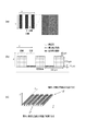
本実施例を説明するにあたり、まず異方性を有するプリント物の構造について図1に示す模式図を用いて説明する。図1(a)は、記録媒体上のxy二次元平面において形成された凹凸形状を表している。x軸方向に凹部と凸部とが繰り返し配置されており、印刷面に正対して観察すると、いわゆる縦の万線パターンになっている。図1(b)は、xz平面における凹凸形状の断面構造を表している。本実施例では、プリンタ解像度が約600dpiであり、1ドットの幅が40μmであるとする。凸部がx軸方向に4ドット、凹部がx軸方向に4ドットの繰り返しの場合、凹凸1サイクルは320μmである。また、この例では、一層(1ドット)の厚さ(高さ)は15μmであり、凸部はz軸方向に10ドット積層して形成される。よって凸部の高さは150μmである。このような微小な凸部と凹部とを有する凹凸層は、観察者からは視認されず、紙や布のような平面的なプリント物に見える。図1(c)は、本実施例により形成されたプリント物において、観察角度の変化に応じて異なる色が観察されることを例示する模式図である。凸部と凹部との表面に形成される画像層の色をそれぞれ指定することによって、視点1で観察するとオクルージョンにより凸部の色のみが観察され、視点2で観察すると凸部と凹部との両面の色が混色された色が観察される。このようなプリント物の構造は一見平面でありながら、観察方向の方位角を変えると、凸部の上に記録された色と凹部の上に記録された色とによって色の見え方が変化する。
[Example 1]
<Structure of printed matter with anisotropy>
In explaining this embodiment, first, the structure of the printed matter having anisotropy will be described with reference to the schematic diagram shown in FIG. FIG. 1A shows a concave-convex shape formed in an xy two-dimensional plane on a recording medium. The concave portion and the convex portion are repeatedly arranged in the x-axis direction, and when observed facing the printed surface, a so-called vertical universal line pattern is formed. FIG. 1B shows a cross-sectional structure having a concavo-convex shape in the xz plane. In this embodiment, it is assumed that the printer resolution is about 600 dpi and the width of one dot is 40 μm. When the convex portion has 4 dots in the x-axis direction and the concave portion has 4 dots in the x-axis direction, one cycle of unevenness is 320 μm. Further, in this example, the thickness (height) of one layer (1 dot) is 15 μm, and the convex portion is formed by laminating 10 dots in the z-axis direction. Therefore, the height of the convex portion is 150 μm. The uneven layer having such minute convex portions and concave portions is not visible to the observer and looks like a flat printed matter such as paper or cloth. FIG. 1 (c) is a schematic view illustrating that different colors are observed in the printed matter formed by this embodiment according to a change in the observation angle. By designating the colors of the image layers formed on the surfaces of the convex and concave parts, only the color of the convex part is observed by occlusion when observed from the
観察角度の変化に応じた観察される色の変化を記録媒体上で表現する場合、有色記録材によって凸部の表面と凹部の表面とに異なる色を記録する。この場合、凸部の表面に記録した有色記録材が凹部の表面に流れ込み、色の再現精度が低下してしまう。本実施例では、凹凸形状に応じて処理を凸部と凹部とで切り替えることによって、凸部の表面に記録した有色記録材が凹部の表面に流れ込むのを抑制する例を説明する。 When expressing the change in the observed color according to the change in the observation angle on the recording medium, different colors are recorded on the surface of the convex portion and the surface of the concave portion by the colored recording material. In this case, the colored recording material recorded on the surface of the convex portion flows into the surface of the concave portion, and the color reproduction accuracy is lowered. In this embodiment, an example will be described in which the colored recording material recorded on the surface of the convex portion is suppressed from flowing into the surface of the concave portion by switching the treatment between the convex portion and the concave portion according to the uneven shape.
<画像処理装置1のハードウェア構成>
画像処理装置1のハードウェア構成を図2(a)を用いて説明する。画像処理装置1は、例えばコンピュータであり、CPU201、ROM202、RAM203を備える。CPU201は、RAM203をワークメモリとして、ROM202、HDD(ハードディスクドライブ)213などに格納されたOS(オペレーティングシステム)や各種プログラムを実行する。また、CPU201は、システムバス208を介して各構成を制御する。尚、後述するフローチャートによる処理は、ROM202やHDD213などに格納されたプログラムコードがRAM203に展開され、CPU201によって実行される。VC(ビデオカード)204には、ディスプレイ215が接続される。汎用I/F(インターフェース)205には、シリアルバス209を介して、マウスやキーボードなどの入力デバイス210や画像形成装置211が接続される。SATA(シリアルATA)I/F206には、シリアルバス212を介して、HDD213や各種記録メディアの読み書きを行う汎用ドライブ214が接続される。NIC(ネットワークインターフェースカード)207は、外部装置との間で情報の入出力を行う。CPU201は、HDD213や汎用ドライブ214にマウントされた各種記録メディアを各種データの格納場所として使用する。CPU201は、プログラムによって提供されるUI(ユーザインターフェース)をディスプレイ215に表示し、入力デバイス210を介して受け付けるユーザ指示などの入力を受信する。
<Hardware configuration of
The hardware configuration of the
<画像処理装置1の論理構成>
図2(b)は、実施例1における画像処理装置1の論理構成を示す図である。画像処理装置1は、第1取得部301と、第2取得部302と、保持部303と、色分解部304と、解析部305と、ハーフトーン処理部306と、形成制御部307と、を有する。
<Logical configuration of
FIG. 2B is a diagram showing a logical configuration of the
第1取得部301は、記録媒体上に形成する画像を表す画像データを取得する。第2取得部302は、記録媒体上に形成する凹凸形状を表す形状データを取得する。保持部303は、画像データが有する色情報と画像形成装置211が備える有色インクの記録量とが対応づけられた色分解LUT(ルックアップテーブル)などのテーブルを保持している。色分解部304は、色情報を有する画像データに対して色分解LUTを用いた色分解処理を行うことによって、有色インクの記録量を表す記録量データを生成する。解析部305は、形状データの解析を行う。ハーフトーン処理部306は、記録量データに対してハーフトーン処理を行うことによって、有色インクのドット配置に対応するドット配置データを生成する。形成制御部307は、ドット配置データが表すドット配置をパス分解することによって、記録走査(パス)ごとのインクドットの配置を決定する。画像形成装置211は、決定された記録走査(パス)ごとのインクドットの配置に基づいて、記録媒体上に凹凸層及び画像層を記録媒体上に形成する。
The
<画像形成装置211の構成>
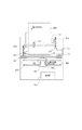
図3は、画像形成装置211の構成図である。画像形成装置211は、インクを用いて、凹凸形状(凹凸層)を形成し、当該凹凸形状の上に色(画像層)を記録するインクジェットプリンタである。ヘッドカートリッジ401は、複数の吐出口からなる記録ヘッドと、この記録ヘッドへインクを供給するインクタンクを有し、また、記録ヘッドの各吐出口を駆動する信号などを受信するためのコネクタが設けられている。インクタンクには、凹凸層を形成するためのクリア(透明)インクと、画像層を形成するためのシアン、マゼンタ、イエロー、ブラックの有色インクと、の計5種が独立に設けられている。これらのインクは紫外線(UV)を照射することにより硬化するUVインクである。尚、クリアインクはわずかな色や濁りがあっても良い。ヘッドカートリッジ401はキャリッジ402に位置決めして交換可能に搭載されており、キャリッジ402には、コネクタを介してヘッドカートリッジ401に駆動信号等を伝達するためのコネクタホルダが設けられている。また、キャリッジ402には、紫外光(UV)照射装置403が搭載されており、吐出されたインクを硬化させ記録媒体上に固着させるために制御される。キャリッジ402は、ガイドシャフト404に沿って往復移動可能となっている。具体的には、キャリッジ402は、主走査モータ405を駆動源としてモータプーリ406、従動プーリ407およびタイミングベルト408等の駆動機構を介して駆動されるとともに、その位置及び移動が制御される。尚、本実施例において、このキャリッジ402のガイドシャフト404に沿った移動を「主走査」といい、移動方向を「主走査方向」と称す。プリント用紙等の記録媒体409は、オートシートフィーダ(以下、ASFと称す)411に載置されている。凹凸層及び画像層を形成する際、給紙モータ412の駆動によってギアを介してピックアップローラ413が回転し、ASF411から記録媒体409が一枚ずつ分離され、給紙される。更に、記録媒体409は、搬送ローラ410の回転によりキャリッジ402上のヘッドカートリッジ401の吐出口面と対向する記録開始位置に搬送される。搬送ローラ410は、ラインフィード(LF)モータ414を駆動源としてギアを介して駆動される。記録媒体409が給紙されたか否かの判定と給紙時位置の確定は、記録媒体409がペーパエンドセンサ415を通過した時点で行われる。キャリッジ402に搭載されたヘッドカートリッジ401は、吐出口面がキャリッジ402から下方へ突出して記録媒体409と平行になるように保持されている。制御部416は、CPUや記憶手段等から構成されており、外部からデータを受け取り、当該データに基づいて画像形成装置211の各パーツの動作を制御する。
<Configuration of
FIG. 3 is a configuration diagram of the
<凹凸層及び画像層の形成動作>
以下、図3に示す構成の画像形成装置211における凹凸層及び画像層を記録媒体上に形成するための動作について説明する。まず、凹凸層を形成するために、記録媒体409が所定の記録開始位置に搬送されると、キャリッジ402がガイドシャフト404に沿って記録媒体409上を移動し、その移動の際に記録ヘッドの吐出口よりクリアインクが吐出される。紫外光照射装置403は記録ヘッドの移動に合わせて紫外光を照射し、吐出されたクリアインクを硬化させ、記録媒体上に固着させる。そして、キャリッジ402がガイドシャフト404の一端まで移動すると、搬送ローラ410が所定量だけ記録媒体409をキャリッジ402の走査方向に垂直な方向に搬送する。本実施例において、この記録媒体409の搬送を「紙送り」または「副走査」と称し、この搬送方向を「紙送り方向」または「副走査方向」と称す。記録媒体409の所定量の搬送が終了すると、再度キャリッジ402はガイドシャフト404に沿って移動する。このように、記録ヘッドのキャリッジ402による走査と紙送りとを繰り返すことにより記録媒体409に凹凸層が形成される。凹凸層が形成された後は、搬送ローラ410が記録媒体409を記録開始位置に戻し、凹凸層の形成と同様のプロセスで凹凸層上にシアン、マゼンタ、イエロー、ブラックの各有色インクを吐出し、画像層を形成する。
<Formation operation of uneven layer and image layer>
Hereinafter, the operation for forming the uneven layer and the image layer on the recording medium in the
本実施例において、記録ヘッドは、説明を簡易にするため、インクドットを吐出するか否かの二値で制御される。これはクリアインクについても有色インクについても同じである。本実施例では、画像形成装置211の出力解像度で定義される画素毎にインクのオンとオフとを制御するものとし、単位面積において全画素をオンにした状態をインクの記録量100%として扱うものとする。ここで、「オン」はインクドットを吐出することを表し、「オフ」はインクを吐出しないことを表す。尚、インクの吐出量が変調可能な記録ヘッドが一般的に使用されているが、上述の二値化処理を変調可能な複数レベルへの多値化処理に拡張すれば適用可能であり、二値化に限定されるものではない。
In this embodiment, the recording head is controlled by a binary value of whether or not to eject ink dots for the sake of simplicity. This is the same for clear ink and colored ink. In this embodiment, the on / off of ink is controlled for each pixel defined by the output resolution of the
本実施例の凹凸層の形成では、上述したようにクリアインクを吐出することによって、位置毎に高さの制御を行う。凹凸層の形成においてクリアインクの記録量100%でほぼ均一な層を記録媒体上に形成した場合、吐出したクリアインクの体積に応じて、層はある高さを有する。例えば、記録量100%で形成された層が15μmの高さを有する場合、75μmの高さを再現するためには、層を5回重ねればよい。つまり、75μmの高さが必要な位置においてクリアインクの記録量は500%となる。 In the formation of the uneven layer of this embodiment, the height is controlled for each position by ejecting the clear ink as described above. When a substantially uniform layer is formed on the recording medium with a recording amount of 100% of the clear ink in the formation of the uneven layer, the layer has a certain height according to the volume of the discharged clear ink. For example, when the layer formed with a recording amount of 100% has a height of 15 μm, the layers may be stacked five times in order to reproduce the height of 75 μm. That is, the recording amount of the clear ink is 500% at the position where the height of 75 μm is required.
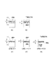
図4は、記録媒体409上を記録ヘッドが走査することによって、凹凸層及び画像層を形成するための動作を説明する図である。キャリッジ402による主走査で記録ヘッドの幅Lだけ層の形成を行い、1ラインの記録が終了する毎に記録媒体409を副走査方向に距離Lずつ搬送する。説明を平易にするため、本実施例における画像形成装置211は一回の走査で記録量100%までのインク吐出しかできないものとし、記録量100%を超える層の形成の場合には、搬送は行わずに同じ領域を複数回走査する。例えば、インクの記録量が最大500%の場合は、同じラインを5回走査する。図4を用いて説明すると、領域Aを記録ヘッドで5回走査した(図4(a))後、記録媒体409を副走査方向に搬送し、領域Bの主走査を5回繰り返す(図4(b))ことになる。
FIG. 4 is a diagram illustrating an operation for forming an uneven layer and an image layer by scanning the recording head on the
尚、記録量100%以下でも複数回の走査、いわゆる多パス印字(マルチパス)を行う場合がある。図4(c)〜(e)に2パス記録の例を示す。この例では、キャリッジ402による主走査で記録ヘッドの幅Lだけ画像の形成を行い、1ラインの記録が終了する毎に記録媒体409を副走査方向に距離L/2ずつ搬送する。領域Aは記録ヘッドのm回目の主走査(図4(c))とm+1回目の主走査(図4(d))により記録され、領域Bは記録ヘッドのm+1回目の主走査(図4(d))とm+2回目の主走査(図4(e))により記録される。ここで、2パス記録の動作を説明したが、何回のパス数で記録するかは、所望の精度に応じて変えることができる。nパス記録を行う場合は、例えば、1ラインの記録が終了する毎に記録媒体409を副走査方向に距離L/Nずつ搬送する。この場合、記録量が100%以下でも複数の印字パターンに分割し、記録媒体409の同一ライン上を記録ヘッドがn回主走査することで凹凸層及び画像層を形成する。尚、本実施例においては、記録媒体409に特に限定はなく、記録ヘッドによる層の形成に対応できるものであれば、紙やプラスチックフィルム等、各種の材料が利用可能である。
Even if the recording amount is 100% or less, scanning may be performed a plurality of times, so-called multi-pass printing (multi-pass). FIGS. 4 (c) to 4 (e) show an example of 2-pass recording. In this example, an image is formed by the width L of the recording head by the main scanning by the
<画像処理装置1が実行する処理の流れ>
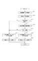
図5は画像処理装置1が実行する処理の流れを示すフローチャートである。
<Flow of processing executed by the
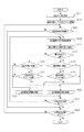
FIG. 5 is a flowchart showing a flow of processing executed by the
ステップS1において、第1取得部301は、色情報としてRGB値が各画素に記録された画像データを取得する。画像データは、画素毎に、視点1においてプリント物を観察することによって視認する色を表す色情報Rφ1,Gφ1,Bφ1、視点2においてプリント物を観察することによって視認する色を表す色情報Rφ2,Gφ2,Bφ2が記録されている。つまり、第1取得部301で取得する画像データは、各画素に異なる2色を表す色情報が記録された6チャンネルの画像データである。ここで、Rφ1,Gφ1,Bφ1,Rφ2,Gφ2,Bφ2は、sRGB空間上で定義されるRGB値とする。尚、画像データが表す色情報は、AdobeRGB空間上で定義されるRGB値あるいはL*a*b*空間上で定義されるL*a*b*値でもよいし、色の三刺激値であるXYZ値、分光反射率などでもよい。また、ステップS1において取得する画像データは1つである必要はない。例えば、画素値としてRφ1,Gφ1,Bφ1が各画素に記録された3チャンネルの画像データと、画素値としてRφ2,Gφ2,Bφ2が各画素に記録された3チャンネルの画像データとを取得してもよい。
In step S1, the
ステップS2において、第2取得部302は、記録媒体上に形成する凹凸形状の高さを表す高さ情報が各画素に記録された形状データを取得する。本実施例において、形状データが表す形状は、図1(a)に示すように所定の方向に凹凸を繰り返すパターンを用いるが、方位角方向に観察角度を変化させた場合に色の見えが異なるプリント物を形成できればどのような凹凸形状であってもよい。例えば、画像の領域ごとに底面の縦横比が異なる凸部が複数配置されて形成される凹凸形状であってもよい。
In step S2, the
ステップS3において、色分解部304は、保持部303より色分解LUTを取得し、取得した色分解LUTを用いた式(1)に示す色分解処理を画像データに対して行うことによって、有色インクの記録量CMYKを表す記録量データを生成する。
In step S3, the

ここで、LUTC,LUTM,LUTY,LUTKは各有色インクについての色分解LUTである。尚、CMYKそれぞれ別々の色分解LUTを用いるのではなく、RGB値とCMYK値とが対応付けられた1つの色分解LUTを用いて色分解処理を行ってもよい。
Here, LUT C , LUT M , LUT Y , and LUT K are color-separated LUTs for each colored ink. Instead of using separate color separation LUTs for each CMYK, the color separation processing may be performed using one color separation LUT in which the RGB value and the CMYK value are associated with each other.
尚、色情報を有する画像データの解像度と高さ情報を有する形状データの解像度とが異なる場合、色分解処理を行う前に、画像データの解像度と形状データの解像度とを一致させる。解像度変換には、公知の二アレストネイバー法やバイリニア法などを用いる。 When the resolution of the image data having the color information and the resolution of the shape data having the height information are different, the resolution of the image data and the resolution of the shape data are matched before the color separation processing is performed. A known two-arrest neighbor method, bilinear method, or the like is used for the resolution conversion.
ステップS4において、解析部305は、ステップS2において取得した形状データを解析する。本ステップの処理の詳細は後述する。ステップS5において、ハーフトーン処理部306は、形状データの解析結果に応じたハーフトーン処理を行う。本ステップの処理の詳細は後述する。ステップS6において、形成制御部307は、ステップS5において得られたドット配置データが表すドット配置をパス分解し、記録走査(パス)ごとのインクドットの配置を決定する。さらに、記録走査(パス)ごとのインクドットの配置を表すプリントデータを画像形成装置211に送信する。また、形状データに基づいて、クリアインクの使用に関するパラメータを算出し、当該パラメータを画像形成装置211に送信した後処理を終了する。ここで、クリアインクの使用に関するパラメータは、クリアインクの記録量やクリアインクのパスごとのドット配置である。当該パラメータは、形状データが表す高さと当該パラメータとが対応付けられたテーブルを用いて算出すればよい。
In step S4, the
<ステップS4において解析部305が実行する処理>
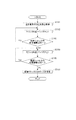
図6はステップS4において解析部305が実行する処理のフローチャートである。
<Process executed by
FIG. 6 is a flowchart of the process executed by the
ステップS411において、ステップS2において取得された形状データを取得する。ステップS412において、ステップS411において取得した形状データが表す形状を複数の領域(ブロック)に分割し、分割後の領域それぞれにデジタルフーリエ変換を行う。尚、本実施例では、縦32画素×横32画素のブロックに領域分割するが、ブロックのサイズはこの一例には限定されない。また、形状データ全体に対してフーリエ変換を行った後、領域分割を行ってもよい。 In step S411, the shape data acquired in step S2 is acquired. In step S412, the shape represented by the shape data acquired in step S411 is divided into a plurality of regions (blocks), and digital Fourier transform is performed on each of the divided regions. In this embodiment, the area is divided into blocks of 32 pixels in length and 32 pixels in width, but the size of the blocks is not limited to this example. Further, the region may be divided after performing the Fourier transform on the entire shape data.
ステップS413において、ステップS412における領域分割により得られた領域のうち1つの領域(注目領域)について、高周波成分を含むか否かを判定する。高周波成分を含む場合はステップS414の処理へ進む。高周波成分を含まない場合は、注目領域には凹凸がないと判定し、注目領域内の画素に凸部でないことを示すフラグ情報0を記録し、ステップS424の処理へ進む。高周波成分を含むか否かの判定は、フーリエ変換によって得られた周波数が所定の閾値より大きいか否かで判定すればよい。
In step S413, it is determined whether or not one region (region of interest) among the regions obtained by the region division in step S412 contains a high frequency component. If it contains a high frequency component, the process proceeds to step S414. When the high frequency component is not included, it is determined that there is no unevenness in the region of interest,
ステップS414において、ステップS413において高周波成分が含まれると判定された領域内の画素のうち注目画素の高さ情報を取得する。ステップS415において、式(2)により、注目画素の高さ情報が表す高さと隣接画素(前の注目画素)の高さ情報が表す高さとの差分値ha(x,y)及びhb(x,y)、及び、傾斜角度θa及びθbを算出する。 In step S414, the height information of the pixel of interest among the pixels in the region determined to contain the high frequency component in step S413 is acquired. In step S415, the difference values h a (x, y) and h b (x, y) and h b (difference values) between the height represented by the height information of the pixel of interest and the height represented by the height information of the adjacent pixel (previous pixel of interest) according to the equation (2). x, y) and the inclination angles θ a and θ b are calculated.
ここで、h(x,y)は画素位置(x,y)の高さを表し、ha(x,y)及びhb(x,y)は注目画素と隣接画素との高さの差分値を表す。また、Dは注目画素と隣接画素との距離を表し、θa及びθbは注目画素の高さから隣接画素の高さへの傾斜角度を表す。尚、距離Dは、プリンタ解像度に応じて決まる値を予めHDD213などの記憶装置に記憶させておくことで用いる。
Here, h (x, y) is the height of the pixel position (x, y), h a (x, y) and h b (x, y) is the difference in height between the target pixel and the adjacent pixels Represents a value. Further, D represents the distance between the pixel of interest and the adjacent pixel, and θ a and θ b represent the inclination angle from the height of the pixel of interest to the height of the adjacent pixel. The distance D is used by storing a value determined according to the printer resolution in a storage device such as
ステップS416において、前の注目画素が凸部に対応する領域であるか否かを判定する。凸部に対応する領域である場合はステップS417へ進み、凹部に対応する領域である場合はステップS419へ進む。尚、最初の注目画素の判定は、隣接画素との高さの比較によって行う。尚、形状データの全画素の高さの平均値と注目画素の高さとの比較によって、注目画素が凸部であるか凹部であるかを判定してもよい。 In step S416, it is determined whether or not the previous pixel of interest is a region corresponding to the convex portion. If the area corresponds to the convex portion, the process proceeds to step S417, and if the area corresponds to the concave portion, the process proceeds to step S419. The first pixel of interest is determined by comparing the height with the adjacent pixel. It should be noted that it may be determined whether the pixel of interest is a convex portion or a concave portion by comparing the average value of the heights of all the pixels of the shape data with the height of the pixel of interest.
ステップS417において、傾斜角度θa及びθbが所定の閾値よりも大きいか否かを判定し、閾値よりも大きい場合はステップS418へと進み、閾値以下の場合は傾斜が小さく前の注目領域と同じ凸部であるためステップS422へと進む。ステップS418において、高さの差分値ha(x,y)及びhb(x,y)を参照し、傾斜方向がプラス方向か否かを判定する。ここでプラス方向は、注目画素の高さを有する形状から隣接画素の高さを有する形状への傾斜が上る方向であり、マイナス方向は、注目画素の高さを有する形状から隣接画素の高さを有する形状への傾斜が下る方向である。プラス方向である場合はステップS421へと進み、マイナス方向である場合はステップS422へと進む。 In step S417, it is determined whether or not the inclination angles θ a and θ b are larger than the predetermined threshold value, and if it is larger than the threshold value, the process proceeds to step S418. Since it is the same convex portion, the process proceeds to step S422. In step S418, it is determined whether or not the inclination direction is the plus direction with reference to the height difference values h a (x, y) and h b (x, y). Here, the plus direction is the direction in which the inclination from the shape having the height of the attention pixel to the shape having the height of the adjacent pixel is increased, and the minus direction is the direction in which the shape having the height of the attention pixel is the height of the adjacent pixel. It is the direction in which the inclination to the shape having is lowered. If it is in the positive direction, the process proceeds to step S421, and if it is in the negative direction, the process proceeds to step S422.
ステップS419において、傾斜角度θa及びθbが所定の閾値よりも大きいか否かを判定し、閾値よりも大きい場合はステップS420へと進み、閾値以下の場合は傾斜が小さく前の注目領域と同じ凹部であるためステップS421へと進む。ステップS420において、高さの差分値ha(x,y)及びhb(x,y)を参照し、傾斜方向がマイナス方向か否かを判定する。マイナス方向である場合はステップS422へと進み、プラス方向である場合はステップS421へと進む。 In step S419, it is determined whether or not the inclination angles θ a and θ b are larger than the predetermined threshold value, and if it is larger than the threshold value, the process proceeds to step S420. Since it is the same recess, the process proceeds to step S421. In step S420, it is determined whether or not the inclination direction is the minus direction with reference to the height difference values h a (x, y) and h b (x, y). If it is in the negative direction, the process proceeds to step S422, and if it is in the positive direction, the process proceeds to step S421.
ステップS421において、注目画素が凹部領域に位置すると判定し、注目画素に凸部でないことを示すフラグ情報0を記録する。ステップS422において、注目画素が凸部領域に位置すると判定し、注目画素に凸部であることを示すフラグ情報1を記録する。
In step S421, it is determined that the pixel of interest is located in the concave region, and the
ステップS423において、高周波成分を含むと判定された領域の全画素について凸部であるか凹部であるか判定を行ったかを判定し、行っていればステップS424の処理へ進み、行っていない場合はステップS414へ戻り処理を進める。ステップS424において、ステップS412において領域分割によって得られた領域全てについて処理を行ったか否かを判定し、行っていれば処理を終了し、行っていない場合はステップS413へ戻り処理を進める。 In step S423, it is determined whether all the pixels in the region determined to contain the high frequency component are convex or concave, and if so, the process proceeds to step S424, and if not, the process proceeds to step S424. Return to step S414 and proceed with the process. In step S424, it is determined whether or not the processing has been performed on all the regions obtained by the area division in step S412, and if it has been performed, the processing is terminated. If not, the process returns to step S413 and the processing proceeds.
尚、本実施例においては、形状が上述の万線パターンのように凹部と凸部とで構成されるとして凹凸のフラグ情報を2値で表した。しかし、別途高さ情報を参照してフラグ情報にステップ数を持たせることで、凸部が連続して連なるような形状データに対応することもできる。 In this embodiment, the flag information of the unevenness is represented by a binary value assuming that the shape is composed of the concave portion and the convex portion as in the above-mentioned Mansen pattern. However, by separately referring to the height information and giving the flag information the number of steps, it is possible to deal with the shape data in which the convex portions are continuously connected.
<ステップS5においてハーフトーン処理部306が実行する処理>
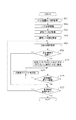
図7はステップS5においてハーフトーン処理部306が実行する処理のフローチャートである。
<Process executed by
FIG. 7 is a flowchart of the process executed by the
ステップS511において、ステップS3において生成された有色インクの記録量データを取得する。ステップS512において、ステップS4における形状データの解析によって得られた解析データを取得する。解析データは、図9(a)に示すように、形状データの画素毎に解析結果であるフラグ情報が記録されている。フラグ情報は、凸部であることを示すフラグ情報1と凹部であることを示すフラグ情報0との2値である。ステップS513において、解析データに基づいて、記録量データにおける注目画素が凸部に対応する領域であるか否かを判定し、凸部に対応する領域である場合はステップS514へ進み、凸部に対応する領域でない場合はステップS517へ進む。
In step S511, the recording amount data of the colored ink generated in step S3 is acquired. In step S512, the analysis data obtained by the analysis of the shape data in step S4 is acquired. As shown in FIG. 9A, the analysis data records flag information, which is an analysis result, for each pixel of the shape data. The flag information is a binary value of
ステップS514において、ステップS513において、記録量データにおける注目画素が含まれる凸部領域とその他の領域との境界位置に対応する記録量と、注目画素の記録量と、を用いて凸部領域とその近傍領域との色差を算出する。境界位置に対応する記録量としては、境界位置のうち注目画素に最も近い画素の記録量を用いればよい。本実施例においては、有色インクの記録量と色値(L*a*b*値)とが対応付けられたLUTを参照することによって、記録量データが表す記録量CMYKをL*a*b*値へと変換し、L*a*b*空間上のユークリッド距離を色差として算出する。尚、境界位置に対応する記録量としては、境界位置における画素値の平均値や最大値などの統計値を用いてもよい。境界位置は、解析データを参照して特定すればよい。 In step S514, in step S513, the convex region and its addition are used by using the recording amount corresponding to the boundary position between the convex region including the pixel of interest and the other region in the recording amount data and the recording amount of the pixel of interest. Calculate the color difference from the neighboring area. As the recording amount corresponding to the boundary position, the recording amount of the pixel closest to the pixel of interest among the boundary positions may be used. In this embodiment, the recording amount CMYK represented by the recording amount data is set to L * a * b by referring to the LUT in which the recording amount of the colored ink and the color value (L * a * b * value) are associated with each other. Convert to * value and calculate the Euclidean distance in L * a * b * space as the color difference. As the recording amount corresponding to the boundary position, a statistical value such as an average value or a maximum value of pixel values at the boundary position may be used. The boundary position may be specified by referring to the analysis data.
ステップS515において、ステップS514において算出した色差が所定の閾値よりも大きいか否かを判定し、閾値よりも大きい場合はステップS517の処理へ進み、閾値以下である場合はステップS516の処理へ進む。本実施例では閾値として3の数値を用いるが、他の数値を用いることもできる。例えば、色差についての閾値は日本色彩学会が定める許容色差に基づいて設定することができる。隣接比較で色差が感じられるレベルにする場合は、閾値を0.8〜1.6に設定する。また、離間比較でほとんど気づかないレベルにするには、閾値を1.6〜3.2に設定する。さらに、印象レベルで同じ色として扱えるレベルにするには、閾値を3.2〜6.5に設定する。 In step S515, it is determined whether or not the color difference calculated in step S514 is larger than a predetermined threshold value, and if it is larger than the threshold value, the process proceeds to step S517, and if it is equal to or less than the threshold value, the process proceeds to step S516. In this embodiment, a numerical value of 3 is used as the threshold value, but other numerical values can also be used. For example, the threshold value for color difference can be set based on the permissible color difference set by the Japan Color Society. Set the threshold to 0.8 to 1.6 if you want to make the color difference noticeable in the adjacency comparison. In addition, the threshold value is set to 1.6 to 3.2 in order to make the level almost unnoticed in the separation comparison. Further, in order to make the impression level treatable as the same color, the threshold value is set to 3.2 to 6.5.
ステップS516において、凸部領域であり、かつ、近傍領域との色差が所定の閾値より大きい領域に対する第1ハーフトーン処理のための第1閾値マトリクスのサイズを決定する。第1ハーフトーン処理は、凸部の端よりも凸部の中央にインクドットを多く配置するためハーフトーン処理である。本ステップの処理の詳細は後述する。 In step S516, the size of the first threshold matrix for the first halftone processing for the convex region and the region whose color difference from the neighboring region is larger than a predetermined threshold is determined. The first halftone process is a halftone process because more ink dots are arranged in the center of the convex portion than at the edge of the convex portion. Details of the processing in this step will be described later.
ステップS517において、凹部領域又は、凸部領域であり、かつ、近傍領域との色差が所定の閾値以下である領域に対する第2ハーフトーン処理のための第2閾値マトリクスのサイズを決定する。第2ハーフトーン処理は、インクドットを離散的に配置するためのハーフトーン処理である。本ステップの処理の詳細は後述する。 In step S517, the size of the second threshold matrix for the second halftone processing for the concave region or the convex region and the region whose color difference from the neighboring region is equal to or less than a predetermined threshold is determined. The second halftone process is a halftone process for arranging the ink dots discretely. Details of the processing in this step will be described later.
ステップS518において、凹部領域又は、凸部領域であり、かつ、近傍領域との色差が所定の閾値以下である領域に対して第2閾値マトリクスを用いた第2ハーフトーン処理を実行し、第2ドット配置データを生成する。ドット配置データは、インクを吐出することを表す0とインクを吐出しないことを表す1との2値を各画素に記録した2値データである。本実施例における第2閾値マトリクスはブルーノイズ特性を有する。図9(a)にブルーノイズ特性を有するドット分散型の第2閾値マトリクスを例示する。 In step S518, the second halftone process using the second threshold matrix is executed for the concave region or the convex region and the region where the color difference from the neighboring region is equal to or less than a predetermined threshold value, and the second halftone processing is performed. Generate dot placement data. The dot arrangement data is binary data in which two values, 0 indicating that ink is ejected and 1 indicating that ink is not ejected, are recorded in each pixel. The second threshold matrix in this embodiment has a blue noise characteristic. FIG. 9A illustrates a dot-dispersed second threshold matrix having a blue noise characteristic.
ステップS519において、凸部領域であり、かつ、近傍領域との色差が所定の閾値より大きい領域に対して第1閾値マトリクスを用いた第1ハーフトーン処理を実行し、第1ドット配置データを生成する。図9(a)にドット集中型の第1閾値マトリクスを例示する。図9(a)における第1閾値マトリクスは、凸部に対応する領域が横方向(x軸方向)に8ドットの幅であるため、凸部の中央は閾値1である2ドット幅の領域である。凸部の中央は、インクの記録量が低い領域で最初にドットを打つことになる領域である。また、凸部の端は閾値255である1ドット幅の領域である。凸部の端は、インクの記録量が高い領域で最後にドットを打つことになる領域である。尚、第1閾値マトリクスは、凸部の中央から凸部の端へ閾値が大きくなるマトリクスであればどのようなものであってもよい。例えば、図9(b)に示すように、横方向(x軸方向)と同様に縦方向(y軸方向)にも閾値が大きくなるようにしてもよいし、凸部の中央から渦巻き状に閾値が大きくなっていてもよい。また、本実施例では凸部の中央の位置が、8ドットうち中央の2ドット幅の領域であったが、上記一例には限定されない。例えば、凸部の幅が5(奇数)ドットであった場合は、中央の1ドット幅の領域を凸部の中央としてもよい。 In step S519, the first halftone process using the first threshold matrix is executed for the region which is the convex region and the color difference from the neighboring region is larger than the predetermined threshold value, and the first dot arrangement data is generated. To do. FIG. 9A illustrates a dot-concentrated first threshold matrix. In the first threshold matrix in FIG. 9A, since the region corresponding to the convex portion has a width of 8 dots in the lateral direction (x-axis direction), the center of the convex portion is a region having a width of 2 dots having a threshold value of 1. is there. The center of the convex portion is an area where dots are first struck in a region where the amount of ink recorded is low. Further, the end of the convex portion is a region having a width of 1 dot, which is a threshold value of 255. The edge of the convex portion is an area where a dot is finally struck in a region where the amount of ink recorded is high. The first threshold matrix may be any matrix as long as the threshold increases from the center of the convex portion to the edge of the convex portion. For example, as shown in FIG. 9B, the threshold value may be increased in the vertical direction (y-axis direction) as well as in the horizontal direction (x-axis direction), or spirally from the center of the convex portion. The threshold value may be large. Further, in this embodiment, the position of the center of the convex portion is a region having a width of 2 dots in the center of the 8 dots, but the present invention is not limited to the above example. For example, when the width of the convex portion is 5 (odd) dots, the region having a width of 1 dot in the center may be the center of the convex portion.
上述したステップS5の処理は、注目画素を含む領域の閾値マトリクスのサイズが決まると、異なる領域における注目画素を選択してS513〜S519まで処理を行う。この処理を全領域のハーフトーン処理が実行されるまで繰り返す。尚、閾値マトリクスのサイズ及び閾値を画像データ及び形状データに基づいて予め決めておいてもよい。この場合、ステップS516及びステップS517の処理は行わず、予め決められた閾値マトリクスを用いてハーフトーン処理を行う。 In the process of step S5 described above, when the size of the threshold matrix of the region including the pixel of interest is determined, the pixels of interest in different regions are selected and the processes are performed from S513 to S519. This process is repeated until the halftone process of the entire area is executed. The size and threshold of the threshold matrix may be determined in advance based on the image data and the shape data. In this case, the processing of step S516 and step S517 is not performed, but the halftone processing is performed using a predetermined threshold matrix.
<ステップS516及びステップS517におけるハーフトーン処理部306が実行する処理>
図8はステップS516及びステップS517においてハーフトーン処理部306が実行する処理のフローチャートである。ステップS513及びステップS515の判定結果が連続して同一である領域を算出し、当該領域のサイズを閾値マトリクスのサイズに設定する。
<Processes executed by the
FIG. 8 is a flowchart of processing executed by the
ステップS5161において、ステップS513及びステップS515において判定された注目画素(x、y)についてその判定結果を取得する。ステップS5162において、カウンタdxを1インクリメントする。ステップS5163において、注目画素(x、y)と画素(x+dx、y)の判定結果を参照し、判定結果が同一であるか否かを判定する。同一である場合はステップS5162へと進み、同一でない場合はステップS5164へと進む。ステップS5164において、カウンタdyを1インクリメントする。 In step S5161, the determination result is acquired for the attention pixel (x, y) determined in step S513 and step S515. In step S5162, the counter dx is incremented by 1. In step S5163, the determination results of the pixel of interest (x, y) and the pixel (x + dx, y) are referred to, and it is determined whether or not the determination results are the same. If they are the same, the process proceeds to step S5162, and if they are not the same, the process proceeds to step S5164. In step S5164, the counter dy is incremented by 1.
ステップS5165において、注目画素(x、y)と画素(x、y+dy)の判定結果を参照し、判定結果が同一であるか否かを判定する。同一である場合はステップS5164へと進み、同一でない場合はステップS5166へと進む。ステップS5166において、閾値マトリクスのサイズを横方向dx−1、縦方向dy−1と設定する。 In step S5165, the determination results of the pixel of interest (x, y) and the pixel (x, y + dy) are referred to, and it is determined whether or not the determination results are the same. If they are the same, the process proceeds to step S5164, and if they are not the same, the process proceeds to step S5166. In step S5166, the size of the threshold matrix is set to dx-1 in the horizontal direction and dy-1 in the vertical direction.
尚、以上のステップS516及びステップS517の処理は、解析データに対して公知のラプラシアンフィルタ等を用いたエッジ検出を行うことによって注目画素を含む領域を特定してもよい。 In the above steps S516 and S517, the region including the pixel of interest may be specified by performing edge detection on the analysis data using a known Laplacian filter or the like.
以上説明したように実施例1によれば、凹凸形状の凸部の上に有色インクを記録する際に、凸部の端よりも中央に多く有色インクが記録されるようにハーフトーン処理を行うことによって、異方性を有するプリント物の色の再現精度を向上させることができる。また、本実施例では、ハーフトーン処理によって凸部の上に記録した有色記録材が凹部に流れ込むのを抑制しているため、凸部の上に記録する有色記録材の記録量に制限がなく、高彩度色の再現を行うことができる。また、予め色情報に対する有色インクの記録量の組み合わせを1つに定めておくことによって、テーブルが複数の記録量の組み合わせを保持しておく必要がない。 As described above, according to the first embodiment, when the colored ink is recorded on the convex portion of the concave-convex shape, the halftone processing is performed so that more colored ink is recorded in the center than the edge of the convex portion. Thereby, the color reproduction accuracy of the printed matter having anisotropy can be improved. Further, in this embodiment, since the colored recording material recorded on the convex portion is suppressed from flowing into the concave portion by the halftone processing, there is no limit to the recording amount of the colored recording material recorded on the convex portion. , Highly saturated colors can be reproduced. Further, by predetermining one combination of the recording amount of the colored ink with respect to the color information, it is not necessary for the table to hold a plurality of combinations of the recording amount.
[実施例2]
実施例1では、凸部の中央にインクドットが集中する閾値マトリクスを設定することにより、色の再現精度を向上させる方法について説明した。実施例2では、パス分解処理によって、凸部の中央に複数のドットを重ねる例について説明する。以下に、実施例1との差分であるステップS6における処理を主に説明する。
[Example 2]
In Example 1, a method of improving the color reproduction accuracy by setting a threshold matrix in which ink dots are concentrated in the center of the convex portion has been described. In the second embodiment, an example in which a plurality of dots are overlapped in the center of the convex portion by the path decomposition process will be described. The process in step S6, which is a difference from the first embodiment, will be mainly described below.
<ステップS6における形成制御部307が実行する処理>
図10はステップS6において形成制御部307が実行する処理のフローチャートである。
<Process executed by the
FIG. 10 is a flowchart of the process executed by the
ステップS621において、ステップS5において生成された有色インクのドット配置データを取得する。尚、ここで取得するドット配置データは、ステップS5において生成されたデータに限らず、記録量データに対して公知のハーフトーン処理を行って得られたデータであってもよい。ステップS622において、ドット配置データに基づいて、パス分解処理を行う。本実施例では、4パスに分解を行う。ステップS623において、ステップS4における形状データの解析によって得られた解析データを取得する。ステップS624において、ステップS516及びステップS517の処理と同様に処理により、凸部又は凹部が連続した領域を特定する。ステップS625において、ステップS624において特定された領域のうち注目領域を設定する。ステップS626において、解析データを参照し、注目領域が凸部であるか凹部であるかを判定する。凸部である場合はステップS627に進み、凹部である場合はステップS630に進む。 In step S621, the dot arrangement data of the colored ink generated in step S5 is acquired. The dot arrangement data acquired here is not limited to the data generated in step S5, and may be data obtained by performing a known halftone process on the recorded amount data. In step S622, path decomposition processing is performed based on the dot arrangement data. In this embodiment, decomposition is performed in 4 passes. In step S623, the analysis data obtained by the analysis of the shape data in step S4 is acquired. In step S624, a region in which the convex portion or the concave portion is continuous is specified by the same processing as in the processing of step S516 and step S517. In step S625, the region of interest among the regions specified in step S624 is set. In step S626, the analysis data is referred to, and it is determined whether the region of interest is a convex portion or a concave portion. If it is a convex portion, the process proceeds to step S627, and if it is a concave portion, the process proceeds to step S630.
ステップS627において、ステップS622におけるパス分解処理によって得られたパスごとのドット配置について、凸部領域の端(凸部と凹部との境界領域)に位置するドットを0にする。尚、凸部の端に配置する配置するドットを0にするのではなく、予め決められたドット数分減少させる補正を行ってもよい。ステップS628において、注目領域において記録量データが表す記録量とステップS627における処理によって得られたドット配置に応じて有色インクを記録した場合の記録量との差分を算出する。差分値が所定の閾値よりも小さい場合はステップS629の処理へ進み、閾値以上の場合はS630の処理へ進む。ステップS629において、凸部領域の中央におけるドット数を増やし、ステップS628の処理へ戻る。 In step S627, regarding the dot arrangement for each path obtained by the path decomposition process in step S622, the dots located at the end of the convex portion region (the boundary region between the convex portion and the concave portion) are set to 0. In addition, instead of setting the dots to be arranged at the end of the convex portion to 0, a correction may be performed to reduce the number of dots by a predetermined number of dots. In step S628, the difference between the recording amount represented by the recording amount data in the region of interest and the recording amount when the colored ink is recorded according to the dot arrangement obtained by the processing in step S627 is calculated. If the difference value is smaller than the predetermined threshold value, the process proceeds to step S629, and if the difference value is greater than or equal to the threshold value, the process proceeds to S630. In step S629, the number of dots in the center of the convex region is increased, and the process returns to step S628.
ステップS630において、全ての領域について処理を終了したかどうかを判定する。処理を終えている場合、ステップS6において決められた有色インクのドット配置を表すプリントデータとクリアインクの使用に関するパラメータとを画像形成装置211に送信し、処理を終了する。終えていない場合、ステップS625の処理へ戻る。クリアインクの使用に関するパラメータは、ステップS630において、形状データに基づいて算出する。
In step S630, it is determined whether or not the processing has been completed for all the areas. When the processing is completed, the print data representing the dot arrangement of the colored ink determined in step S6 and the parameters related to the use of the clear ink are transmitted to the
以上説明したように実施例2によれば、パス分解処理によって、凸部の端に配置されたドットを減少させることによって、凸部の上に記録された有色インクが凹部に流れ込むことを抑制し、異方性を有するプリント物の色の再現精度を向上させることができる。 As described above, according to the second embodiment, the path decomposition process reduces the number of dots arranged at the edges of the convex portion, thereby suppressing the colored ink recorded on the convex portion from flowing into the concave portion. , It is possible to improve the color reproduction accuracy of printed matter having anisotropy.
[実施例3]
実施例1及び実施例2では、凸部の中央に有色インクのドットが集中するようなハーフトーン処理、または、パス分解処理を行うことにより、色の再現精度を向上させる方法について説明した。実施例3では、凸部の上に記録された有色インクが凹部に流れ込むことを抑制するために、図12のように凸部の端にクリアインクを盛り上げるようパス分解処理を行う例を説明する。以下に、実施例1との差分であるステップS6における処理を主に説明する。
[Example 3]
In Examples 1 and 2, a method of improving the color reproduction accuracy by performing a halftone process or a path decomposition process in which dots of colored ink are concentrated in the center of the convex portion has been described. In the third embodiment, in order to prevent the colored ink recorded on the convex portion from flowing into the concave portion, an example in which the pass decomposition process is performed so as to raise the clear ink on the edge of the convex portion as shown in FIG. 12 will be described. .. The process in step S6, which is a difference from the first embodiment, will be mainly described below.
<ステップS6における形成制御部307が実行する処理>
図11は、ステップS6において生成制御部307が実行する処理のフローチャートである。
<Process executed by the
FIG. 11 is a flowchart of the process executed by the
ステップS621において、ステップS5において生成された有色インクのドット配置データを取得する。尚、ここで取得するドット配置データは、ステップS5において生成されたデータに限らず、記録量データに対して公知のハーフトーン処理を行って得られたデータであってもよい。さらに、クリアインクのドット配置データを取得する。クリアインクのドット配置データは、形状データに基づいて予め生成しておく。ステップS622において、ドット配置データに基づいて、パス分解処理を行う。本実施例では、4パスに分解を行う。ステップS623において、ステップS4における形状データの解析によって得られた解析データを取得する。ステップS624において、ステップS516及びステップS517の処理と同様に処理により、凸部又は凹部が連続した領域を特定する。ステップS625において、ステップS624において特定された領域のうち注目領域を設定する。ステップS626において、解析データを参照し、注目領域が凸部であるか凹部であるかを判定する。凸部である場合はステップS627に進み、凹部である場合はステップS630に進む。 In step S621, the dot arrangement data of the colored ink generated in step S5 is acquired. The dot arrangement data acquired here is not limited to the data generated in step S5, and may be data obtained by performing a known halftone process on the recorded amount data. Further, the dot arrangement data of the clear ink is acquired. The clear ink dot arrangement data is generated in advance based on the shape data. In step S622, path decomposition processing is performed based on the dot arrangement data. In this embodiment, decomposition is performed in 4 passes. In step S623, the analysis data obtained by the analysis of the shape data in step S4 is acquired. In step S624, a region in which the convex portion or the concave portion is continuous is specified by the same processing as in the processing of step S516 and step S517. In step S625, the region of interest among the regions specified in step S624 is set. In step S626, the analysis data is referred to, and it is determined whether the region of interest is a convex portion or a concave portion. If it is a convex portion, the process proceeds to step S627, and if it is a concave portion, the process proceeds to step S630.
ステップS627において、ステップS622におけるパス分解処理によって得られたパスごとの有色インクのドット配置について、凸部領域の端(凸部と凹部との境界領域)に位置するドットを0にする。さらに、クリアインクのドット配置において、凸部の端の位置のドット数を1増加させる。尚、凸部の端に配置する配置する有色インクのドットを0にするのではなく、予め決められたドット数分減少させる補正を行ってもよい。ステップS628において、注目領域において記録量データが表す記録量とステップS627における処理によって得られたドット配置に応じて有色インクを記録した場合の記録量との差分を算出する。差分値が所定の閾値よりも小さい場合はステップS629の処理へ進み、閾値以上の場合はS630の処理へ進む。ステップS629において、凸部領域の中央におけるドット数を増やし、ステップS628の処理へ戻る。 In step S627, regarding the dot arrangement of the colored ink for each path obtained by the path decomposition process in step S622, the dots located at the end of the convex region (the boundary region between the convex and the concave) are set to 0. Further, in the dot arrangement of the clear ink, the number of dots at the position of the edge of the convex portion is increased by 1. In addition, instead of setting the dots of the colored ink arranged at the end of the convex portion to 0, a correction may be performed to reduce the dots by a predetermined number of dots. In step S628, the difference between the recording amount represented by the recording amount data in the region of interest and the recording amount when the colored ink is recorded according to the dot arrangement obtained by the processing in step S627 is calculated. If the difference value is smaller than the predetermined threshold value, the process proceeds to step S629, and if the difference value is greater than or equal to the threshold value, the process proceeds to S630. In step S629, the number of dots in the center of the convex region is increased, and the process returns to step S628.
ステップS630において、全ての領域について処理を終了したかどうかを判定する。処理を終えている場合、ステップS6において決められた有色インクのドット配置を表すプリントデータとクリアインクの使用に関するパラメータとを画像形成装置211に送信し、処理を終了する。終えていない場合、ステップS625の処理へ戻る。
In step S630, it is determined whether or not the processing has been completed for all the areas. When the processing is completed, the print data representing the dot arrangement of the colored ink determined in step S6 and the parameters related to the use of the clear ink are transmitted to the
以上説明したように実施例3によれば、凸部の端をクリアインクを用いて盛り上げることによって、凸部の上に記録された有色インクが凹部に流れ込むことを抑制し、色の再現精度を向上させることが可能となる。 As described above, according to the third embodiment, by raising the edge of the convex portion with clear ink, the colored ink recorded on the convex portion is suppressed from flowing into the concave portion, and the color reproduction accuracy is improved. It is possible to improve.
[実施例4]
上述した実施例では、凸部の上に記録された有色インクが凹部に流れ込みにくくするためのハーフトーン処理及びパス分解処理を行った。実施例4では、色分解処理において、凸部の上に記録する有色インクの複数の記録量の組み合わせから、凹部に流れ込みにくい記録量の組み合わせを選択する例について説明する。以下に、実施例1との差分であるステップS3における処理を主に説明する。尚、本実施例のステップS1において取得する画像データは色情報としてCIE三刺激値XYZを有することとする。つまり、画素毎に、視点1においてプリント物を観察することによって視認する色を表す色情報XYZ1、視点2においてプリント物を観察することによって視認する色を表す色情報XYZ2が記録されている。
[Example 4]
In the above-described embodiment, a halftone treatment and a path decomposition treatment were performed to prevent the colored ink recorded on the convex portion from flowing into the concave portion. In the fourth embodiment, an example of selecting a combination of recording amounts that are difficult to flow into the concave portion from a combination of a plurality of recording amounts of the colored ink recorded on the convex portion in the color separation process will be described. The process in step S3, which is a difference from the first embodiment, will be mainly described below. The image data acquired in step S1 of this embodiment has a CIE tristimulus value XYZ as color information. That is, for each pixel, the color information XYZ1 representing the color visually recognized by observing the printed matter at the
<ステップS3において色分解部304が実行する処理>
図13は、ステップS3において色分解部304が実行する処理のフローチャートである。
<Process executed by the
FIG. 13 is a flowchart of the process executed by the
ステップS321において、色分解LUTを取得する。図14に示すように、本実施例における色分LUTは、画像形成装置211が搭載する有色インクC(シアン)、M(マゼンタ)、Y(イエロー)、K(ブラック)に対し、各有色インクの記録量に応じて再現される色(CIE三刺激値XYZ)を表す。つまり、色分解LUTは、有色インクの記録量CMYKとCIE三刺激値XYZとが対応付けられたデータである。尚、この色分解LUTは、有色インクの記録量を変えながら記録媒体上にパッチを形成し、形成されたパッチの色を測定することで予め作成しておき、HDD213等の記憶装置に記憶させておく。
In step S321, the color separation LUT is acquired. As shown in FIG. 14, the color component LUT in this embodiment is different from the colored inks C (cyan), M (magenta), Y (yellow), and K (black) mounted on the
ステップS322において、ステップS1で取得した画像データの色情報に基づいて、凸部に記録する有色インクの色(XYZ凸)と凹部に記録する有色インクの色(XYZ凹)とを算出する。図15における組み合わせ1のように、視点1で色情報が表す色(XYZ1)、視点2で色情報が表す色(XYZ2)を再現するためには、凸部に記録する有色インクの色(XYZ凸)によってXYZ1を表現する必要がある。さらに、凸部と凹部とに記録する有色インクの色の混色((XYZ凸+XYZ凹)/2)によってXYZ2を表現する必要がある。よって、凸部と凹部との面積が同一である場合、XYZ凸とXYZ凹は式(3)によって算出される。
In step S322, based on the color information of the image data acquired in step S1, the color of the colored ink recorded in the convex portion (XYZ convex ) and the color of the colored ink recorded in the concave portion (XYZ concave ) are calculated. In order to reproduce the color represented by the color information at the viewpoint 1 (XYZ1) and the color represented by the color information at the viewpoint 2 (XYZ2) as in the
ステップS323において、ステップS322で算出したXYZ凸とXYZ凹とに基づいて、凸部に記録する有色インクの記録量CMYK凸と凹部に記録する有色インクのCMYK凹を取得する。取得は、図14に示す色変換テーブルから、立方体補間や四面体補間などの公知の補間処理を用いて、逆引きを行う。ここで扱う色変換テーブルは有色インクの記録量CMYKに対するCIE三刺激値XYZを表し、有色インクCMYに対して公知のUCR処理を行ったものである。そのため、XYZに対して複数のCMYKが存在することとなる。そこで、取得したXYZに対するCMYKの全ての候補から、ステップS324において適切な組み合わせを選択する。
In step S323, based on the XYZ convex and XYZ concave calculated in step S322, the recording amount of the colored ink recorded in the convex portion and the CMYK concave of the colored ink recorded in the concave portion are acquired. The acquisition is performed by reverse lookup from the color conversion table shown in FIG. 14 using known interpolation processing such as cubic interpolation and tetrahedral interpolation. The color conversion table handled here represents the CIE tristimulus value XYZ for the recording amount CMYK of the colored ink, and the colored ink CMY is subjected to a known UCR process. Therefore, there are a plurality of CMYKs for XYZ. Therefore, an appropriate combination is selected in step S324 from all the CMYK candidates for the acquired XYZ.
ステップS324において、ステップS323において取得されたCMYKの候補のうち、適切な記録量CMYKの組み合わせを選択する。具体的には、凸部については、凸部に記録した有色インクが凹部に流れこむのを抑制するために、凸部に記録する有色インクそれぞれの記録量の総記録量が最も少なくなるCMYK凸を選択する。凹部については、粒状性を悪化させないために、凹部に記録する有色インクそれぞれの記録量の総記録量が最も多くなるCMYK凹を選択する。本実施例において、総記録量はC、M、Y、Kの各記録量を加算した総量とする。以上の処理により、凸部に記録する有色インクが凹部に流れづらくなるため、2つの異なる方向で再現したい色の差が小さくなるのを抑制し、観察角度に伴う色の見えの変化を視認しやすくなる。 In step S324, an appropriate combination of recording amount CMYK is selected from the CMYK candidates acquired in step S323. Specifically, for the convex portion, in order to prevent the colored ink recorded in the convex portion from flowing into the concave portion, the total recording amount of each colored ink recorded in the convex portion is the smallest CMYK convex. Select. As for the concave portion, the CMYK concave portion that maximizes the total recording amount of each colored ink recorded in the concave portion is selected so as not to deteriorate the graininess. In this embodiment, the total recorded amount is the total amount obtained by adding the recorded amounts of C, M, Y, and K. By the above processing, it becomes difficult for the colored ink to be recorded in the convex portion to flow into the concave portion, so that the difference between the colors to be reproduced in the two different directions is suppressed from becoming small, and the change in the appearance of the color with the observation angle is visually recognized. It will be easier.
以上説明したように、CMYK4色を搭載したプリンタでは、UCR処理により有色インクの記録量の組み合わせが複数算出される。本実施例では、このプリンタを用いて表面に凹凸形状を有するプリント物を形成する際に、凸部の上に記録する有色インクの記録量を削減するため、総記録量が最少となる有色インクの組み合わせを選択した。これにより、凸部の上に記録したインクが凹部に流れづらくなるため、所望の色を高精度で再現できる。さらに、凹凸形状の上に異なる方向から観察した場合に色が異なって見えるように有色インクを記録することで、記録媒体上で色の異方性を再現することが可能となる。 As described above, in the printer equipped with CMYK 4 colors, a plurality of combinations of the recording amounts of the colored inks are calculated by the UCR process. In this embodiment, in order to reduce the recording amount of the colored ink recorded on the convex portion when forming a printed matter having an uneven shape on the surface using this printer, the colored ink that minimizes the total recording amount. I chose the combination of. This makes it difficult for the ink recorded on the convex portion to flow into the concave portion, so that the desired color can be reproduced with high accuracy. Further, by recording the colored ink on the uneven shape so that the colors look different when observed from different directions, it is possible to reproduce the anisotropy of the color on the recording medium.
[変形例]
上述した実施例では、形状データを解析することによって、凸部であるか凹部であるかを判定したが、上記一例には限定されない。予め凸と凹部とが特定された形状データを取得してもよいし、形状データとは別に凹部と凸部とを特定するマスクデータを取得してもよい。マスクデータを取得する場合、マスクデータに基づいてハーフトーン処理における閾値マトリクスを切り替える。尚、形状データを予め生成しておく際に、凸部の幅を凹部の幅より広くしておくことによって、凸部の上に記録したインクが凹部に流れづらくすることができる。
[Modification example]
In the above-described embodiment, it is determined whether the portion is a convex portion or a concave portion by analyzing the shape data, but the present invention is not limited to the above-mentioned example. The shape data in which the convex and the concave portion are specified in advance may be acquired, or the mask data for specifying the concave portion and the convex portion may be acquired separately from the shape data. When acquiring mask data, the threshold matrix in halftone processing is switched based on the mask data. When the shape data is generated in advance, by making the width of the convex portion wider than the width of the concave portion, it is possible to make it difficult for the ink recorded on the convex portion to flow into the concave portion.
また、上述した実施例では、インクジェット方式を採用して凹凸層及び画像層を形成する例を示したが、電子写真方式などその他の記録方式であってもよい。 Further, in the above-described embodiment, an example in which the concave-convex layer and the image layer are formed by adopting the inkjet method is shown, but other recording methods such as the electrophotographic method may be used.
また、上述した実施例では、ハーフトーン処理を閾値マトリクスを用いて行ったが、誤差拡散法を用いてもよい。この場合、凸部の端に対応する記録量は0にするか、又は、凸部の中央に加算し、凸部の中央領域のみに誤差が拡散するように拡散係数を決定する。 Further, in the above-described embodiment, the halftone processing is performed using the threshold matrix, but an error diffusion method may be used. In this case, the recording amount corresponding to the edge of the convex portion is set to 0, or is added to the center of the convex portion, and the diffusion coefficient is determined so that the error is diffused only in the central region of the convex portion.
また、上述した実施例では、凹凸を形成するためのクリアインクをUVインクとしたが、上記一例には限定されない。例えば、UV以外の光で硬化するインクであってもよいし、熱で硬化するインクであってもよい。また、削ることで凹凸を形成してもよく、樹脂以外に木材や金属を用いてもよい。 Further, in the above-described embodiment, the clear ink for forming the unevenness is UV ink, but the present invention is not limited to the above-mentioned example. For example, it may be an ink that is cured by light other than UV, or an ink that is cured by heat. Further, unevenness may be formed by scraping, and wood or metal may be used in addition to the resin.
また、上述した実施例では、画像形成装置211に搭載されている有色インクがC、M、Y、Kの4種として説明したが、上記一例に限定されない。C、M、Y、Kに加えてLc(ライトシアン)、Lm(ライトマゼンタ)等の低濃度インクを用いてもよい。この場合、LcをCに、LmをMに置き換えるなどの濃淡分解を行うことによって、有色インクの記録量の組み合わせが増えることになる。実施例4においては、その組み合わせから総記録量が最少となる有色インクの記録量の組み合わせを選択すればよい。尚、上述した低濃度インク以外にもR(赤)インク、G(緑)インク、B(青)インクなどの特色インクを用いてもよい。
Further, in the above-described embodiment, the colored inks mounted on the
また、上述した実施例では、方位角が異なる2つの視点からプリント物を観察した場合に再現する色情報を有する画像データを取得したが、上記一例には限定されない。表面に凹凸形状を有するプリント物は視点の仰角方向の変化によっても見え方が変化するため、仰角が異なる2つの視点からプリント物を観察した場合に再現する色情報を画像データが有していても良い。 Further, in the above-described embodiment, image data having color information to be reproduced when the printed matter is observed from two viewpoints having different azimuth angles is acquired, but the present invention is not limited to the above-mentioned example. Since the appearance of a printed matter having an uneven shape on the surface changes depending on the change in the elevation angle direction of the viewpoint, the image data has color information to be reproduced when the printed matter is observed from two viewpoints having different elevation angles. Is also good.
また、上述した実施例では、有色記録材として有色インクを用いたが、上記一例に限定されない。例えば、有色記録材として有色トナーを用いてもよい。凹凸を形成するための記録材についても、クリアインクに限定されず、クリアトナーであってもよい。 Further, in the above-described embodiment, colored ink is used as the colored recording material, but the present invention is not limited to the above-mentioned example. For example, colored toner may be used as the colored recording material. The recording material for forming the unevenness is not limited to the clear ink, and may be a clear toner.
また、上述した実施例では、画像データに対して色分解処理を行うことによって、記録量データを生成したが、上記一例には限定されない。画像データに基づいて生成した記録量データを予めHDD213などの記憶装置に記憶させておき、そこから記録量データを取得して用いてもよい。この場合、画像処理装置1は、画像データの取得と色分解処理を行わない。
Further, in the above-described embodiment, the recording amount data is generated by performing the color separation processing on the image data, but the present invention is not limited to the above-mentioned example. The recorded amount data generated based on the image data may be stored in a storage device such as
また、上述した実施例では、形状データの各画素には高さ情報が記録されていたが、記録媒体上に形成する凹凸形状を表すことができればどのような形式であってもよい。例えば、各画素に形状表面の法線方向が記録されていてもよい。また、形状データは、点群データやポリゴンデータであってもよい。 Further, in the above-described embodiment, the height information is recorded in each pixel of the shape data, but any format may be used as long as the uneven shape formed on the recording medium can be represented. For example, the normal direction of the shape surface may be recorded in each pixel. Further, the shape data may be point cloud data or polygon data.
また、上述した実施例では、形状データに基づいて、クリアインクの使用に関するパラメータを算出する例を示したが、上記一例には限定されない。例えば、形状データに基づいて算出されたクリアインクの使用に関するパラメータを予めHDD213などの記憶装置に記憶させておき、そこから当該パラメータを取得して用いてもよい。
Further, in the above-described embodiment, an example of calculating parameters related to the use of clear ink based on the shape data has been shown, but the present invention is not limited to the above-mentioned example. For example, a parameter related to the use of clear ink calculated based on the shape data may be stored in a storage device such as
また、上述した実施例では、凸部と凹部とでハーフトーン処理を切り替えたが、どちらも同じドット集中型の第1閾値マトリクスを用いた第1ハーフトーン処理を行ってもよい。 Further, in the above-described embodiment, the halftone processing is switched between the convex portion and the concave portion, but the first halftone processing using the same dot-concentrated first threshold matrix may be performed in both cases.
また、実施例4では、凸部に記録する有色インクそれぞれの記録量の総記録量が最も少なくなるCMYK凸を選択する例を説明した。しかし、凸部に記録する有色インクが凹部に流れづらくなる所定の条件に応じてCMYK凸を選択するのであればどのような選択方法でもよい。例えば、平均粘度が最大となるCMYK凸を選択してもよい。また、UCR処理による粒状性の悪化を考慮し、所定の閾値以下の総記録量となる組み合わせのうち総記録量が最も多い組み合わせを選択してもよい。 Further, in Example 4, an example of selecting the CMYK convex that minimizes the total recording amount of each of the colored inks recorded on the convex portion has been described. However, any selection method may be used as long as the CMYK convex is selected according to a predetermined condition that makes it difficult for the colored ink to be recorded in the convex portion to flow into the concave portion. For example, the CMYK convex that maximizes the average viscosity may be selected. Further, in consideration of deterioration of graininess due to the UCR treatment, the combination having the largest total recording amount among the combinations having the total recording amount equal to or less than a predetermined threshold value may be selected.
[その他の実施例]
本発明は、上述の実施例の1以上の機能を実現するプログラムを、ネットワーク又は記憶媒体を介してシステム又は装置に供給し、そのシステム又は装置のコンピュータにおける1つ以上のプロセッサーがプログラムを読出し実行する処理でも実現可能である。また、1以上の機能を実現する回路(例えば、ASIC)によっても実現可能である。
[Other Examples]
The present invention supplies a program that realizes one or more functions of the above-described embodiment to a system or device via a network or storage medium, and one or more processors in the computer of the system or device reads and executes the program. It can also be realized by the processing to be performed. It can also be realized by a circuit (for example, ASIC) that realizes one or more functions.
1 画像処理装置
306 ハーフトーン処理部
1
Claims (19)
前記有色記録材の記録量を表す記録量データを取得する第1取得手段と、
前記凹凸の凸部の上に記録する前記有色記録材のドットを前記凸部の端より前記凸部の中央に多く配置するための第1ハーフトーン処理を前記記録量データに対して行うハーフトーン処理手段と、
を有することを特徴とする画像処理装置。 An image processing device that generates data for different colors of the convex and concave portions of the unevenness by recording a colored recording material on at least the convex portions of the uneven surface on the surface of the recording medium.
A first acquisition means for acquiring recording amount data representing the recording amount of the colored recording material, and
A halftone that performs a first halftone process on the recording amount data for arranging more dots of the colored recording material to be recorded on the convex portion of the unevenness in the center of the convex portion than the edge of the convex portion. Processing means and
An image processing device characterized by having.
前記形状データを解析することによって、前記凹凸における注目領域が前記第1ハーフトーン処理を行う領域か否かを判定する解析手段と、をさらに有し、
前記ハーフトーン処理手段は、前記解析手段による判定の結果に基づいて、前記第1ハーフトーン処理を行うことを特徴とする請求項1に記載の画像処理装置。 A second acquisition means for acquiring shape data representing the shape of the unevenness, and
By analyzing the shape data, the analysis means for determining whether or not the region of interest in the unevenness is the region where the first halftone processing is performed is further provided.
The image processing apparatus according to claim 1, wherein the halftone processing means performs the first halftone processing based on the result of determination by the analysis means.
前記形状データを解析することによって、前記凹凸における注目領域が前記凸部に対応する領域であるか、又は、前記凹凸の凹部に対応する領域であるかを判定する解析手段と、をさらに有し、
前記ハーフトーン処理手段は、前記解析手段によって前記注目領域が前記凸部に対応する領域であると判定された場合、前記記録量データにおける前記注目領域に対応する領域に対して前記第1ハーフトーン処理を行うことを特徴とする請求項1に記載の画像処理装置。 A second acquisition means for acquiring shape data representing the shape of the unevenness, and
By analyzing the shape data, it further has an analysis means for determining whether the region of interest in the unevenness is a region corresponding to the convex portion or a region corresponding to the concave portion of the unevenness. ,
When the analysis means determines that the region of interest is a region corresponding to the convex portion, the halftone processing means refers to the first halftone with respect to the region corresponding to the region of interest in the recorded amount data. The image processing apparatus according to claim 1, wherein processing is performed.
前記ハーフトーン処理手段は、前記解析手段によって前記差分が前記所定の閾値より大きいと判定された場合は、前記記録量データにおける前記注目領域に対応する領域に対して前記第1ハーフトーン処理を行い、前記解析手段によって前記差分が前記所定の閾値以下であると判定された場合は、前記記録量データにおける前記注目領域に対応する領域に対して前記第2ハーフトーン処理を行うことを特徴とする請求項4に記載の画像処理装置。 When the analysis means determines that the region of interest is a region corresponding to the convex portion, the analysis means determines the difference between the color recorded in the region of interest and the color recorded in the region near the region of interest by the colored recording material. It is a means for calculating and determining whether or not the difference is larger than a predetermined threshold value.
When the analysis means determines that the difference is larger than the predetermined threshold value, the halftone processing means performs the first halftone processing on the region corresponding to the region of interest in the recorded amount data. When the analysis means determines that the difference is equal to or less than the predetermined threshold value, the second halftone process is performed on the region corresponding to the region of interest in the recorded amount data. The image processing apparatus according to claim 4.
前記色情報に基づいて、前記記録量データを生成する色分解手段と、をさらに有し、
前記第1取得手段は、前記色分解手段によって生成された前記記録量データを取得することを特徴とする請求項1乃至請求項6のいずれか一項に記載の画像処理装置。 A third acquisition means for acquiring color information representing two different colors for each of the uneven regions, and
Further, it has a color separation means for generating the recorded amount data based on the color information.
The image processing apparatus according to any one of claims 1 to 6, wherein the first acquisition means acquires the recorded amount data generated by the color separation means.
前記記録量データは、前記凹凸の上に前記有色記録材を記録するためのデータであり、前記記録量データが表す前記画像の各画素は、前記凹凸の凸部と凹部とのいずれかに対応する記録量が記録されており、
前記凸部の端は、前記記録量データが表す画像における前記凸部に対応する領域のうち、前記凸部に対応する領域と前記凹部に対応する領域との境界の近傍領域であって、
前記凸部の中央は、前記記録量データが表す画像における前記凸部に対応する領域のうち、前記境界の近傍領域以外の領域であることを特徴とする請求項1乃至請求項14のいずれか一項に記載の画像処理装置。 The first acquisition means acquires recording amount data representing an image having a plurality of pixels and the recording amount of the colored recording material recorded in each pixel.
The recording amount data is data for recording the colored recording material on the unevenness, and each pixel of the image represented by the recording amount data corresponds to either a convex portion or a concave portion of the unevenness. The amount of data to be recorded is recorded,
The end of the convex portion is a region near the boundary between the region corresponding to the convex portion and the region corresponding to the concave portion in the region corresponding to the convex portion in the image represented by the recorded amount data.
Any of claims 1 to 14, wherein the center of the convex portion is a region other than the region near the boundary in the region corresponding to the convex portion in the image represented by the recorded amount data. The image processing apparatus according to claim 1.
前記記録媒体上における前記有色記録材のドット配置に対応するドット配置データを取得する取得手段と、
前記凹凸の凸部の上に記録する前記有色記録材のドットを前記凸部の端より前記凸部の中央に多く配置するためのパス分解処理を前記ドット配置データに対して行うパス分解手段と、
を有することを特徴とする画像処理装置。 An image processing device that generates data for different colors of the convex and concave portions of the unevenness by recording a colored recording material on at least the convex portions of the uneven surface on the surface of the recording medium.
An acquisition means for acquiring dot arrangement data corresponding to the dot arrangement of the colored recording material on the recording medium, and
A path decomposition means for performing a path decomposition process for arranging more dots of the colored recording material to be recorded on the convex portion of the unevenness in the center of the convex portion than the edge of the convex portion on the dot arrangement data. ,
An image processing device characterized by having.
前記有色記録材の記録量を表す記録量データを取得する取得ステップと、
前記凹凸の凸部の上に記録する前記有色記録材のドットを前記凸部の端より前記凸部の中央に多く配置するためのハーフトーン処理を前記記録量データに対して行うハーフトーン処理ステップと、
を有することを特徴とする画像処理方法。 An image processing method for generating data for different colors of the convex and concave portions of the unevenness by recording a colored recording material on at least the convex portions of the uneven surface on the surface of the recording medium.
The acquisition step of acquiring the recording amount data representing the recording amount of the colored recording material, and
A halftone processing step of performing halftone processing on the recording amount data for arranging more dots of the colored recording material to be recorded on the convex portion of the unevenness in the center of the convex portion than the edge of the convex portion. When,
An image processing method characterized by having.
前記記録媒体上における前記有色記録材のドット配置に対応するドット配置データを取得する取得ステップと、
前記凹凸の凸部の上に記録する前記有色記録材のドットを前記凸部の端より前記凸部の中央に多く配置するためのパス分解処理を前記ドット配置データに対して行うパス分解ステップと、
を有することを特徴とする画像処理方法。 An image processing method for generating data for different colors of the convex and concave portions of the unevenness by recording a colored recording material on at least the convex portions of the uneven surface on the surface of the recording medium.
An acquisition step of acquiring dot arrangement data corresponding to the dot arrangement of the colored recording material on the recording medium, and
A path decomposition step for arranging more dots of the colored recording material to be recorded on the convex portion of the unevenness in the center of the convex portion than the edge of the convex portion on the dot arrangement data. ,
An image processing method characterized by having.
Priority Applications (2)
| Application Number | Priority Date | Filing Date | Title |
|---|---|---|---|
| JP2017107453A JP6900239B2 (en) | 2017-05-31 | 2017-05-31 | Image processing equipment, image processing methods and programs |
| US15/987,644 US10486432B2 (en) | 2017-05-31 | 2018-05-23 | Image processing apparatus, image processing method, and storage medium |
Applications Claiming Priority (1)
| Application Number | Priority Date | Filing Date | Title |
|---|---|---|---|
| JP2017107453A JP6900239B2 (en) | 2017-05-31 | 2017-05-31 | Image processing equipment, image processing methods and programs |
Publications (3)
| Publication Number | Publication Date |
|---|---|
| JP2018202635A JP2018202635A (en) | 2018-12-27 |
| JP2018202635A5 JP2018202635A5 (en) | 2020-07-30 |
| JP6900239B2 true JP6900239B2 (en) | 2021-07-07 |
Family
ID=64458345
Family Applications (1)
| Application Number | Title | Priority Date | Filing Date |
|---|---|---|---|
| JP2017107453A Active JP6900239B2 (en) | 2017-05-31 | 2017-05-31 | Image processing equipment, image processing methods and programs |
Country Status (2)
| Country | Link |
|---|---|
| US (1) | US10486432B2 (en) |
| JP (1) | JP6900239B2 (en) |
Families Citing this family (3)
| Publication number | Priority date | Publication date | Assignee | Title |
|---|---|---|---|---|
| US10430974B2 (en) * | 2016-10-28 | 2019-10-01 | Canon Kabushiki Kaisha | Image processing apparatus, image processing method, and storage medium |
| EP3591954A1 (en) * | 2018-07-04 | 2020-01-08 | OCE Holding B.V. | Method for improving mechanical robustness of a color print |
| JPWO2022102074A1 (en) | 2020-11-13 | 2022-05-19 |
Family Cites Families (7)
| Publication number | Priority date | Publication date | Assignee | Title |
|---|---|---|---|---|
| US20090091591A1 (en) * | 2007-10-07 | 2009-04-09 | Yohanan Sivan | Printing Systems And Methods For Generating Relief Images |
| JP2010162695A (en) * | 2009-01-13 | 2010-07-29 | Seiko Epson Corp | Inkjet printer |
| JP6287352B2 (en) * | 2014-03-04 | 2018-03-07 | 株式会社リコー | Image processing apparatus, image processing program, image processing method, and image processing system |
| JP2016013671A (en) * | 2014-07-03 | 2016-01-28 | キヤノン株式会社 | Convexoconcave formation device and convexoconcave formation method |
| JP2017052124A (en) * | 2015-09-07 | 2017-03-16 | 大日本印刷株式会社 | Transfer foil and manufacturing method of printed matter |
| JP6765794B2 (en) | 2015-09-08 | 2020-10-07 | キヤノン株式会社 | Image processing equipment, image processing methods, and programs |
| JP6755739B2 (en) * | 2016-07-28 | 2020-09-16 | キヤノン株式会社 | Image processing equipment, image processing methods and programs |
-
2017
- 2017-05-31 JP JP2017107453A patent/JP6900239B2/en active Active
-
2018
- 2018-05-23 US US15/987,644 patent/US10486432B2/en active Active
Also Published As
| Publication number | Publication date |
|---|---|
| US10486432B2 (en) | 2019-11-26 |
| JP2018202635A (en) | 2018-12-27 |
| US20180345680A1 (en) | 2018-12-06 |
Similar Documents
| Publication | Publication Date | Title |
|---|---|---|
| CN108025557B (en) | Print product, image processing apparatus, image processing method, and computer-readable storage medium | |
| JP5729950B2 (en) | Image processing apparatus and image processing method | |
| JP2016013671A (en) | Convexoconcave formation device and convexoconcave formation method | |
| JP6900239B2 (en) | Image processing equipment, image processing methods and programs | |
| US10459325B2 (en) | Image processing apparatus, image processing method, and storage medium | |
| US10538113B2 (en) | Image processing apparatus, image processing method, and storage medium | |
| JP5147862B2 (en) | Inkjet recording apparatus and inkjet recording method | |
| JP5616719B2 (en) | Image forming apparatus and image forming method | |
| US10005289B2 (en) | Printing apparatus, printing method, and non-transitory computer readable medium for storing program | |
| JP6755739B2 (en) | Image processing equipment, image processing methods and programs | |
| US9855764B2 (en) | Recording apparatus, recording system, and recording method | |
| JP6442294B2 (en) | Image data generation method, image recording method, image data generation device, and image recording device | |
| JP2019107880A (en) | Image processing device, image processing method and program | |
| US10481476B2 (en) | Image processing apparatus, image processing method, and storage medium | |
| JP6891011B2 (en) | Image processing equipment, image processing methods and programs | |
| US20120314234A1 (en) | Image processing apparatus, image printing apparatus and image processing method | |
| WO2019124137A1 (en) | Image processing device, image processing method, and program | |
| JP2012111183A (en) | Recording apparatus, and recording method | |
| JP6855293B2 (en) | Image processing equipment, image processing methods and programs | |
| JP6461255B2 (en) | Image processing apparatus, image processing method, and program | |
| JP2020069699A (en) | Image processing device, image processing method and program | |
| JP2022050987A (en) | Image processing device, image processing method, and program | |
| JP2018074383A (en) | Image processing apparatus, image processing method and program | |
| US20180079212A1 (en) | Printing apparatus, printing method, and non-transitory computer readable medium for storing program | |
| JP2018078537A (en) | Image processing device, image processing method and program |
Legal Events
| Date | Code | Title | Description |
|---|---|---|---|
| A521 | Request for written amendment filed |
Free format text: JAPANESE INTERMEDIATE CODE: A523 Effective date: 20170621 |
|
| A521 | Request for written amendment filed |
Free format text: JAPANESE INTERMEDIATE CODE: A523 Effective date: 20200528 |
|
| A621 | Written request for application examination |
Free format text: JAPANESE INTERMEDIATE CODE: A621 Effective date: 20200528 |
|
| A977 | Report on retrieval |
Free format text: JAPANESE INTERMEDIATE CODE: A971007 Effective date: 20210325 |
|
| A131 | Notification of reasons for refusal |
Free format text: JAPANESE INTERMEDIATE CODE: A131 Effective date: 20210406 |
|
| A521 | Request for written amendment filed |
Free format text: JAPANESE INTERMEDIATE CODE: A523 Effective date: 20210510 |
|
| TRDD | Decision of grant or rejection written | ||
| A01 | Written decision to grant a patent or to grant a registration (utility model) |
Free format text: JAPANESE INTERMEDIATE CODE: A01 Effective date: 20210518 |
|
| A61 | First payment of annual fees (during grant procedure) |
Free format text: JAPANESE INTERMEDIATE CODE: A61 Effective date: 20210616 |
|
| R151 | Written notification of patent or utility model registration |
Ref document number: 6900239 Country of ref document: JP Free format text: JAPANESE INTERMEDIATE CODE: R151 |