JP6765794B2 - Image processing equipment, image processing methods, and programs - Google Patents
Image processing equipment, image processing methods, and programs Download PDFInfo
- Publication number
- JP6765794B2 JP6765794B2 JP2015177011A JP2015177011A JP6765794B2 JP 6765794 B2 JP6765794 B2 JP 6765794B2 JP 2015177011 A JP2015177011 A JP 2015177011A JP 2015177011 A JP2015177011 A JP 2015177011A JP 6765794 B2 JP6765794 B2 JP 6765794B2
- Authority
- JP
- Japan
- Prior art keywords
- color
- color material
- amount
- image processing
- printed matter
- Prior art date
- Legal status (The legal status is an assumption and is not a legal conclusion. Google has not performed a legal analysis and makes no representation as to the accuracy of the status listed.)
- Active
Links
- 238000012545 processing Methods 0.000 title claims description 18
- 238000003672 processing method Methods 0.000 title claims description 5
- 239000000463 material Substances 0.000 claims description 60
- 239000003086 colorant Substances 0.000 claims description 8
- 238000006243 chemical reaction Methods 0.000 claims description 6
- 238000004590 computer program Methods 0.000 claims 1
- 239000000976 ink Substances 0.000 description 84
- 238000000034 method Methods 0.000 description 35
- 230000008569 process Effects 0.000 description 23
- 238000010586 diagram Methods 0.000 description 17
- 230000007704 transition Effects 0.000 description 14
- 230000015572 biosynthetic process Effects 0.000 description 10
- 239000013598 vector Substances 0.000 description 8
- 230000008859 change Effects 0.000 description 7
- 238000012546 transfer Methods 0.000 description 5
- 238000012937 correction Methods 0.000 description 4
- 230000004044 response Effects 0.000 description 4
- 238000004040 coloring Methods 0.000 description 3
- 230000000694 effects Effects 0.000 description 3
- 238000004891 communication Methods 0.000 description 2
- 230000006866 deterioration Effects 0.000 description 2
- 230000006870 function Effects 0.000 description 2
- 230000007246 mechanism Effects 0.000 description 2
- 239000000203 mixture Substances 0.000 description 2
- 238000002834 transmittance Methods 0.000 description 2
- PXFBZOLANLWPMH-UHFFFAOYSA-N 16-Epiaffinine Natural products C1C(C2=CC=CC=C2N2)=C2C(=O)CC2C(=CC)CN(C)C1C2CO PXFBZOLANLWPMH-UHFFFAOYSA-N 0.000 description 1
- 239000000853 adhesive Substances 0.000 description 1
- 230000001070 adhesive effect Effects 0.000 description 1
- 230000007423 decrease Effects 0.000 description 1
- 238000011161 development Methods 0.000 description 1
- 230000001747 exhibiting effect Effects 0.000 description 1
- 239000004744 fabric Substances 0.000 description 1
- 238000007429 general method Methods 0.000 description 1
- 230000010365 information processing Effects 0.000 description 1
- 230000001678 irradiating effect Effects 0.000 description 1
- 238000010030 laminating Methods 0.000 description 1
- 230000000737 periodic effect Effects 0.000 description 1
- 230000002093 peripheral effect Effects 0.000 description 1
- 239000002985 plastic film Substances 0.000 description 1
- 229920006255 plastic film Polymers 0.000 description 1
- 239000011347 resin Substances 0.000 description 1
- 229920005989 resin Polymers 0.000 description 1
- 230000035945 sensitivity Effects 0.000 description 1
- 230000007480 spreading Effects 0.000 description 1
- 230000009466 transformation Effects 0.000 description 1
- 238000009281 ultraviolet germicidal irradiation Methods 0.000 description 1
- 230000000007 visual effect Effects 0.000 description 1
- 238000009736 wetting Methods 0.000 description 1
- 239000002759 woven fabric Substances 0.000 description 1
Images


Classifications
-
- B—PERFORMING OPERATIONS; TRANSPORTING
- B41—PRINTING; LINING MACHINES; TYPEWRITERS; STAMPS
- B41J—TYPEWRITERS; SELECTIVE PRINTING MECHANISMS, i.e. MECHANISMS PRINTING OTHERWISE THAN FROM A FORME; CORRECTION OF TYPOGRAPHICAL ERRORS
- B41J2/00—Typewriters or selective printing mechanisms characterised by the printing or marking process for which they are designed
- B41J2/005—Typewriters or selective printing mechanisms characterised by the printing or marking process for which they are designed characterised by bringing liquid or particles selectively into contact with a printing material
- B41J2/01—Ink jet
- B41J2/21—Ink jet for multi-colour printing
- B41J2/2107—Ink jet for multi-colour printing characterised by the ink properties
- B41J2/2114—Ejecting transparent or white coloured liquids, e.g. processing liquids
-
- B—PERFORMING OPERATIONS; TRANSPORTING
- B41—PRINTING; LINING MACHINES; TYPEWRITERS; STAMPS
- B41J—TYPEWRITERS; SELECTIVE PRINTING MECHANISMS, i.e. MECHANISMS PRINTING OTHERWISE THAN FROM A FORME; CORRECTION OF TYPOGRAPHICAL ERRORS
- B41J2/00—Typewriters or selective printing mechanisms characterised by the printing or marking process for which they are designed
- B41J2/005—Typewriters or selective printing mechanisms characterised by the printing or marking process for which they are designed characterised by bringing liquid or particles selectively into contact with a printing material
- B41J2/01—Ink jet
- B41J2/205—Ink jet for printing a discrete number of tones
- B41J2/2054—Ink jet for printing a discrete number of tones by the variation of dot disposition or characteristics, e.g. dot number density, dot shape
-
- B—PERFORMING OPERATIONS; TRANSPORTING
- B41—PRINTING; LINING MACHINES; TYPEWRITERS; STAMPS
- B41J—TYPEWRITERS; SELECTIVE PRINTING MECHANISMS, i.e. MECHANISMS PRINTING OTHERWISE THAN FROM A FORME; CORRECTION OF TYPOGRAPHICAL ERRORS
- B41J2/00—Typewriters or selective printing mechanisms characterised by the printing or marking process for which they are designed
- B41J2/005—Typewriters or selective printing mechanisms characterised by the printing or marking process for which they are designed characterised by bringing liquid or particles selectively into contact with a printing material
- B41J2/01—Ink jet
- B41J2/21—Ink jet for multi-colour printing
- B41J2/2107—Ink jet for multi-colour printing characterised by the ink properties
- B41J2/2114—Ejecting transparent or white coloured liquids, e.g. processing liquids
- B41J2/2117—Ejecting white liquids
-
- B—PERFORMING OPERATIONS; TRANSPORTING
- B42—BOOKBINDING; ALBUMS; FILES; SPECIAL PRINTED MATTER
- B42D—BOOKS; BOOK COVERS; LOOSE LEAVES; PRINTED MATTER CHARACTERISED BY IDENTIFICATION OR SECURITY FEATURES; PRINTED MATTER OF SPECIAL FORMAT OR STYLE NOT OTHERWISE PROVIDED FOR; DEVICES FOR USE THEREWITH AND NOT OTHERWISE PROVIDED FOR; MOVABLE-STRIP WRITING OR READING APPARATUS
- B42D25/00—Information-bearing cards or sheet-like structures characterised by identification or security features; Manufacture thereof
- B42D25/30—Identification or security features, e.g. for preventing forgery
- B42D25/324—Reliefs
-
- B—PERFORMING OPERATIONS; TRANSPORTING
- B42—BOOKBINDING; ALBUMS; FILES; SPECIAL PRINTED MATTER
- B42D—BOOKS; BOOK COVERS; LOOSE LEAVES; PRINTED MATTER CHARACTERISED BY IDENTIFICATION OR SECURITY FEATURES; PRINTED MATTER OF SPECIAL FORMAT OR STYLE NOT OTHERWISE PROVIDED FOR; DEVICES FOR USE THEREWITH AND NOT OTHERWISE PROVIDED FOR; MOVABLE-STRIP WRITING OR READING APPARATUS
- B42D25/00—Information-bearing cards or sheet-like structures characterised by identification or security features; Manufacture thereof
- B42D25/30—Identification or security features, e.g. for preventing forgery
- B42D25/328—Diffraction gratings; Holograms
-
- B—PERFORMING OPERATIONS; TRANSPORTING
- B44—DECORATIVE ARTS
- B44F—SPECIAL DESIGNS OR PICTURES
- B44F1/00—Designs or pictures characterised by special or unusual light effects
- B44F1/08—Designs or pictures characterised by special or unusual light effects characterised by colour effects
- B44F1/14—Iridescent effects
-
- H—ELECTRICITY
- H04—ELECTRIC COMMUNICATION TECHNIQUE
- H04N—PICTORIAL COMMUNICATION, e.g. TELEVISION
- H04N1/00—Scanning, transmission or reproduction of documents or the like, e.g. facsimile transmission; Details thereof
- H04N1/46—Colour picture communication systems
-
- H—ELECTRICITY
- H04—ELECTRIC COMMUNICATION TECHNIQUE
- H04N—PICTORIAL COMMUNICATION, e.g. TELEVISION
- H04N1/00—Scanning, transmission or reproduction of documents or the like, e.g. facsimile transmission; Details thereof
- H04N1/46—Colour picture communication systems
- H04N1/54—Conversion of colour picture signals to a plurality of signals some of which represent particular mixed colours, e.g. for textile printing
-
- B—PERFORMING OPERATIONS; TRANSPORTING
- B41—PRINTING; LINING MACHINES; TYPEWRITERS; STAMPS
- B41J—TYPEWRITERS; SELECTIVE PRINTING MECHANISMS, i.e. MECHANISMS PRINTING OTHERWISE THAN FROM A FORME; CORRECTION OF TYPOGRAPHICAL ERRORS
- B41J2/00—Typewriters or selective printing mechanisms characterised by the printing or marking process for which they are designed
- B41J2/005—Typewriters or selective printing mechanisms characterised by the printing or marking process for which they are designed characterised by bringing liquid or particles selectively into contact with a printing material
- B41J2/01—Ink jet
- B41J2/21—Ink jet for multi-colour printing
-
- B—PERFORMING OPERATIONS; TRANSPORTING
- B41—PRINTING; LINING MACHINES; TYPEWRITERS; STAMPS
- B41J—TYPEWRITERS; SELECTIVE PRINTING MECHANISMS, i.e. MECHANISMS PRINTING OTHERWISE THAN FROM A FORME; CORRECTION OF TYPOGRAPHICAL ERRORS
- B41J3/00—Typewriters or selective printing or marking mechanisms characterised by the purpose for which they are constructed
- B41J3/407—Typewriters or selective printing or marking mechanisms characterised by the purpose for which they are constructed for marking on special material
-
- B—PERFORMING OPERATIONS; TRANSPORTING
- B41—PRINTING; LINING MACHINES; TYPEWRITERS; STAMPS
- B41M—PRINTING, DUPLICATING, MARKING, OR COPYING PROCESSES; COLOUR PRINTING
- B41M3/00—Printing processes to produce particular kinds of printed work, e.g. patterns
- B41M3/14—Security printing
- B41M3/148—Transitory images, i.e. images only visible from certain viewing angles
-
- H—ELECTRICITY
- H04—ELECTRIC COMMUNICATION TECHNIQUE
- H04N—PICTORIAL COMMUNICATION, e.g. TELEVISION
- H04N1/00—Scanning, transmission or reproduction of documents or the like, e.g. facsimile transmission; Details thereof
- H04N1/46—Colour picture communication systems
- H04N1/56—Processing of colour picture signals
- H04N1/60—Colour correction or control
Description
本発明は、観察方向で色の変化する対象物の色再現に関する。 The present invention relates to color reproduction of an object whose color changes in the observation direction.
ベルベットに代表されるような織物は、表面の複雑な微細形状に起因して、観察する角度を変えると見え方が大きく変化する異方性反射特性を持つ。一般的な異方性反射特性の実現にはレンチキュラーレンズの利用が考えられる。特許文献1では、光硬化樹脂を含むインクを吐出して任意の凹凸が形成可能なUV硬化型インクジェットプリンタを用いることで、レンチキュラーレンズ及びレンチキュラーレンズに接着する画像を同時に形成する技術が開示されている。
Woven fabrics such as velvet have anisotropic reflection characteristics in which the appearance changes significantly when the observation angle is changed due to the complicated fine shape of the surface. The use of a lenticular lens can be considered to realize general anisotropic reflection characteristics.
しかしながら、レンチキュラーレンズを用いた方法では、観察角度を変えた際に滑らかに色を変化させたい場合には、接着画像を高解像度に印刷する必要がある。また、特許文献1のように、インクジェットプリンタを用いてレンチキュラーレンズの曲面形状を高解像度に精度良く形成することは容易ではない。
However, in the method using a lenticular lens, if it is desired to change the color smoothly when the observation angle is changed, it is necessary to print the adhesive image at a high resolution. Further, as in
そこで本発明は、異方性反射特性を有する対象物を、レンチキュラーレンズを用いずに得ることを目的とする。 Therefore, an object of the present invention is to obtain an object having anisotropic reflection characteristics without using a lenticular lens.
また、上記課題を解決するために、本発明に係る画像処理装置は、印刷媒体上の凹凸の上に色材を記録することによって、異なる方向から観察した場合に異なる色が視認される印刷物を形成するために、前記色材の量を決定する画像処理装置であって、前記印刷物を第1観察方向から観察した場合に視認される第1色を表す第1色情報を取得する第1取得手段と、前記印刷物を前記第1観察方向とは異なる第2観察方向から観察した場合に視認され、前記第1色とは異なる第2色を表す第2色情報を取得する第2取得手段と、前記印刷物を前記第1観察方向から観察した場合に前記第1色が視認され、前記印刷物を前記第2観察方向から観察した場合に前記第2色が視認されるように、前記凹凸の凹部の上に記録する第1色材量と前記凹凸の凸部の上に記録する第2色材量とを決定する決定手段と、を有し、前記第1色と前記第2色との少なくとも一方は、前記第1色材量の色材が記録された前記凹部の色と、前記第2色材量の色材が記録された前記凸部の色と、の混色により表現されることを特徴とする。 Further, in order to solve the above problems, the image processing apparatus according to the present invention records a coloring material on unevenness on a print medium, so that a printed matter in which different colors are visually recognized when observed from different directions can be obtained. The first acquisition which is an image processing apparatus which determines the amount of the color material for forming, and acquires the 1st color information which represents the 1st color which is visually recognized when the printed matter is observed from the 1st observation direction. Means and second acquisition means for acquiring second color information that is visually recognized when the printed matter is observed from a second observation direction different from the first observation direction and represents a second color different from the first color. The concave and convex recesses so that the first color is visually recognized when the printed matter is observed from the first observation direction, and the second color is visually recognized when the printed matter is observed from the second observation direction. determining means for determining a second color material amount to be recorded on the protruding portion of the first color material amount and the uneven recording, it was perforated over at least between the second color and the first color One is expressed by a mixture of the color of the concave portion in which the color material of the first color material amount is recorded and the color of the convex portion in which the color material of the second color material amount is recorded. It is a feature.
また、上記課題を解決するために、本発明に係る画像処理方法は、印刷媒体上の凹凸の上に色材を記録することによって、異なる方向から観察した場合に異なる色が視認される印刷物を形成するために、前記色材の量を決定する画像処理方法であって、前記印刷物を第1観察方向から観察した場合に視認される第1色を表す第1色情報を取得する第1取得工程と、前記印刷物を前記第1観察方向とは異なる第2観察方向から観察した場合に視認され、前記第1色とは異なる第2色を表す第2色情報を取得する第2取得工程と、前記印刷物を前記第1観察方向から観察した場合に前記第1色が視認され、前記印刷物を前記第2観察方向から観察した場合に前記第2色が視認されるように、前記凹凸の凹部の上に記録する第1色材量と前記凹凸の凸部の上に記録する第2色材量とを決定する決定工程と、を有し、前記第1色と前記第2色との少なくとも一方は、前記第1色材量の色材が記録された前記凹部の色と、前記第2色材量の色材が記録された前記凸部の色と、の混色により表現されることを特徴とする。 Further, in order to solve the above problems, the image processing method according to the present invention records a coloring material on unevenness on a print medium, so that a printed matter in which different colors are visually recognized when observed from different directions can be obtained. First acquisition, which is an image processing method for determining the amount of the color material for forming, and acquires first color information representing the first color that is visually recognized when the printed matter is observed from the first observation direction. A step and a second acquisition step of acquiring second color information that is visually recognized when the printed matter is observed from a second observation direction different from the first observation direction and represents a second color different from the first color. The concave and convex recesses so that the first color is visually recognized when the printed matter is observed from the first observation direction, and the second color is visually recognized when the printed matter is observed from the second observation direction. a determination step of determining a second color material amount to be recorded on the protruding portion of the first color material amount and the uneven recording, was perforated over at least between the second color and the first color One is expressed by a mixture of the color of the concave portion in which the color material of the first color material amount is recorded and the color of the convex portion in which the color material of the second color material amount is recorded. It is a feature.
本発明は、異方性反射特性を有する対象物を、レンチキュラーレンズを用いずに得ることができる。 According to the present invention, an object having anisotropic reflection characteristics can be obtained without using a lenticular lens.
以下、図面を参照して本発明を詳細に説明する。 Hereinafter, the present invention will be described in detail with reference to the drawings.
本実施例では、異方性の情報として、二つの観察方向とそれぞれの方向から画像を観察した際の色情報を入力し、この情報に応じて凹凸形状と色画像を形成する画像形成装置および方法について記載する。 In this embodiment, as the anisotropy information, an image forming apparatus that inputs two observation directions and color information when observing an image from each direction and forms a concave-convex shape and a color image according to this information. Describe the method.
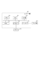
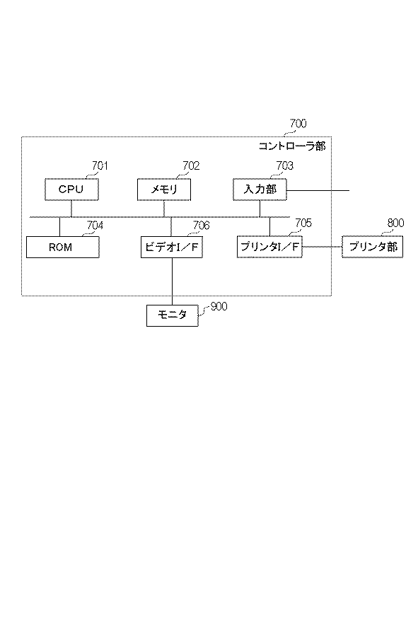
(画像形成装置のハードウエア構成)
図1は、画像形成装置のハードウエア構成を示すブロック図である。図1において、情報処理装置としてのホスト700は、例えばコンピュータであり、マイクロプロセッサ(CPU)701と、ランダムアクセスメモリなどのメモリ702を備える。また、キーボードなどの入力部703、ハードディスクドライブなどのROM704を備える。ホスト700はさらに画像形成手段としてのプリンタ部800との間の通信インタフェイス(以下「プリンタI/F」)705と、モニタ900との間の通信インタフェイス(以下「ビデオI/F」)706を備える。
(Hardware configuration of image forming apparatus)
FIG. 1 is a block diagram showing a hardware configuration of an image forming apparatus. In FIG. 1, the
CPU701は、ROM704から読み出されメモリ702に格納されたプログラムに従って後述する種々の処理を実行する。これらのプログラムはROM704に記憶しておくか、或いは不図示の外部装置から供給される。また、ホスト700はビデオI/F706を介してモニタ900に種々の情報を出力させると共に、入力部703を通じて各種情報を入力する。また、ホスト700はプリンタI/F705を介してプリンタ部800と接続されており、後述する処理によって生成された信号をプリンタ部800に送信して記録を行わせると共に、プリンタ部800から各種情報を受け取る。
The
(プリンタ部の概略構成)
図2は、本実施例に示すプリンタ部の構成図である。プリンタ部800としては、画像形成材であるインクを用いて形状、色の記録を行うインクジェットプリンタを想定する。ヘッドカートリッジ801は、複数の吐出口からなる記録ヘッドと、この記録ヘッドへインクを供給するインクタンクを有し、また、記録ヘッドの各吐出口を駆動する信号などを受信するためのコネクタが設けられている。
(Outline configuration of printer section)
FIG. 2 is a configuration diagram of the printer unit shown in this embodiment. As the
以降、インクにより形成され、凸部と凹部とを繰り返す構造である凹凸形状を表す層、画像の色を表す層をそれぞれ、凹凸層、画像層と称する。インクタンクは、凹凸層を形成するためのクリアインク、画像層を形成するためのシアン、マゼンタ、イエロー、ブラックの色インクの計5種が独立に設けられている。これらのインクは紫外線を照射することにより硬化するUV硬化性インクである。 Hereinafter, a layer representing an uneven shape and a layer representing an image color, which are formed of ink and have a structure in which convex portions and concave portions are repeated, are referred to as an uneven layer and an image layer, respectively. The ink tank is independently provided with a total of five types of clear ink for forming an uneven layer and cyan, magenta, yellow, and black color inks for forming an image layer. These inks are UV curable inks that are cured by irradiating with ultraviolet rays.
ヘッドカートリッジ801はキャリッジ802に位置決めして交換可能に搭載されており、キャリッジ802には、コネクタを介してヘッドカートリッジ801に駆動信号等を伝達するためのコネクタホルダが設けられている。また、キャリッジ802には、紫外光照射部815が搭載されており、吐出されたインクを硬化させ記録媒体(印刷媒体)上に固着させるために制御される。キャリッジ802は、ガイドシャフト803に沿って往復移動可能となっている。具体的には、キャリッジ802は、主走査モータ804を駆動源としてモータプーリ805、従動プーリ806およびタイミングベルト807等の駆動機構を介して駆動されるとともに、その位置及び移動が制御される。尚、このキャリッジ802のガイドシャフト803に沿った移動を「主走査」といい、移動方向を「主走査方向」という。
The
プリント用紙等の記録媒体808は、オートシートフィーダ(以下「ASF」)810に載置されている。画像形成時、給紙モータ811の駆動によってギアを介してピックアップローラ812が回転し、ASF810から記録媒体808が一枚ずつ分離され、給紙される。更に、記録媒体808は、搬送ローラ809の回転によりキャリッジ802上のヘッドカートリッジ801の吐出口面と対向する記録開始位置に搬送される。搬送ローラ809は、ラインフィード(LF)モータ813を駆動源としてギアを介して駆動される。
A
記録媒体808が給紙されたか否かの判定と給紙時位置の確定は、記録媒体808がペーパエンドセンサ814を通過した時点で行われる。キャリッジ802に搭載されたヘッドカートリッジ801は、吐出口面がキャリッジ802から下方へ突出して記録媒体808と平行になるように保持されている。制御部820は、CPUや記憶手段等から構成されており、外部から観察条件とその条件での色情報を含む画像データを受け取り、画像データに基づいてプリンタ部800の各パーツの動作を制御する。
The determination of whether or not the
(凹凸層、画像層の形成動作)
以下、図2に示す構成のインクジェットプリンタにおける凹凸層、画像層の形成動作について説明する。まず、凹凸層を形成するために、記録媒体808が所定の記録開始位置に搬送されると、キャリッジ802がガイドシャフト803に沿って記録媒体808上を移動し、その移動の際に記録ヘッドの吐出口よりインクが吐出される。紫外光照射部815は記録ヘッドの移動に合わせて紫外光を照射し、吐出されたクリアインクを硬化させ、記録媒体上に固着させる。そして、キャリッジ802がガイドシャフト803の一端まで移動すると、搬送ローラ809が所定量だけ記録媒体808をキャリッジ802の走査方向に垂直な方向に搬送する。この記録媒体808の搬送を「紙送り」または「副走査」といい、この搬送方向を「紙送り方向」または「副走査方向」という。記録媒体808の所定量の搬送が終了すると、再度キャリッジ802はガイドシャフト803に沿って移動する。このように、記録ヘッドのキャリッジ802による走査と紙送りとを繰り返すことにより記録媒体808全体に凹凸層が形成される。凹凸層が形成された後は、搬送ローラ809が記録媒体808を記録開始位置に戻し、凹凸層形成と同様のプロセスで凹凸層上にシアン、マゼンタ、イエロー、ブラックの各色インクを吐出し、画像層を形成する。
(Formation operation of uneven layer and image layer)
Hereinafter, the operation of forming the uneven layer and the image layer in the inkjet printer having the configuration shown in FIG. 2 will be described. First, when the
本実施例において、記録ヘッドは、説明を簡易にするため、基本的にインク滴を吐出するか否かの二値の制御で表現される。これはクリアインクについても色インクについても同じである。本実施例では、プリンタ部の出力解像度で定義される画素毎にインクのオン・オフを制御するものとし、単位面積において全画素をオンにした状態をインク量100%として扱うものとする。なお、インクの吐出量が変調可能な記録ヘッドが一般的に使用されているが、上述の二値化処理を変調可能な複数レベルへの多値化処理に拡張すれば適用可能であり、二値化に限定されるものではない。 In this embodiment, the recording head is basically represented by binary control of whether or not to eject ink droplets for the sake of simplicity. This is the same for clear ink and color ink. In this embodiment, the on / off of ink is controlled for each pixel defined by the output resolution of the printer unit, and the state in which all the pixels are turned on in a unit area is treated as 100% of the ink amount. A recording head in which the ink ejection amount can be modulated is generally used, but it can be applied by extending the above-mentioned binarization process to a multi-valued process having multiple levels that can be modulated. It is not limited to digitization.
本実施例の凹凸層形成では、前述のインク量の概念を用いて位置毎に高さの制御を行う。凹凸層形成においてインク量100%でほぼ均一な層を形成した場合、吐出したインクの体積に応じて、層はある厚さ=高さを有する。例えば、インク量100%で形成された層が15μmの厚さを有する場合、75μmの厚さを再現するには、層を5回重ねればよい。つまり、75μmの高さが必要な位置に打ち込むインク量は500%となる。 In the formation of the uneven layer of this embodiment, the height is controlled for each position using the above-mentioned concept of ink amount. When a substantially uniform layer is formed with an amount of ink of 100% in the uneven layer formation, the layer has a certain thickness = height according to the volume of the ejected ink. For example, when the layer formed with 100% ink amount has a thickness of 15 μm, the layers may be stacked five times in order to reproduce the thickness of 75 μm. That is, the amount of ink to be applied to a position where a height of 75 μm is required is 500%.
図3は、記録媒体808上を記録ヘッドが走査することで凹凸層、画像層を形成する動作を説明する図である。
FIG. 3 is a diagram illustrating an operation of forming an uneven layer and an image layer by scanning the
キャリッジ802による主走査で記録ヘッドの幅Lだけ層形成を行い、1ラインの記録が終了する毎に記録媒体808を副走査方向に距離Lずつ搬送する。説明を平易にするため、本実施例におけるプリンタ部は一回の走査でインク量100%までのインク吐出しかできないものとし、インク量100%を超える層形成の場合には、搬送は行わずに同じ領域を複数回走査する。例えば、打ち込むインク量が最大500%の場合は、同じラインを5回走査する。図3を用いて説明すると、領域Aを記録ヘッドで5回走査した(図3(a))後、記録媒体808を副走査方向に搬送し、領域Bの主走査を5回繰り返す(図3(b))ことになる。
A layer is formed by the width L of the recording head by the main scanning by the
なお、記録ヘッドの駆動精度に起因する周期ムラ等の画質劣化を抑制するために、インク量100%以下でも複数回の走査、いわゆる多パス印字を行う場合がある。図3(c)〜(e)に2パス記録の例を示す。この例では、キャリッジ802による主走査で記録ヘッドの幅Lだけ画像形成を行い、1ラインの記録が終了する毎に記録媒体808を副走査方向に距離L/2ずつ搬送する。領域Aは記録ヘッドのm回目の主走査(図3(c))とm+1回目の主走査(図3(d))により記録され、領域Bは記録ヘッドのm+1回目の主走査(図3(d))とm+2回目の主走査(図3(e))により記録される。ここで、2パス記録の動作を説明したが、何回のパス数で記録するかは、所望の精度に応じて変えることができる。nパス記録を行う場合は、例えば、1ラインの記録が終了する毎に記録媒体808を副走査方向に距離L/nずつ搬送する。この場合、インク量が100%以下でも複数の印字パターンに分割し記録媒体の同一ライン上を記録ヘッドがn回主走査することで凹凸層、画像層を形成する。本実施例では、上述の多パス印字による走査と100%以上のインクを打ち込むための走査との混同を防ぐため、多パス印字は行わないものとし、複数回の走査は、層を積層するためのものとして説明する。なお、本実施例においては、記録媒体に特に限定はなく、記録ヘッドによる画像形成に対応できるものであれば、紙やプラスチックフィルム等、各種の材料が利用可能である。
In addition, in order to suppress image quality deterioration such as periodic unevenness due to the driving accuracy of the recording head, scanning a plurality of times, so-called multi-pass printing, may be performed even if the ink amount is 100% or less. FIGS. 3 (c) to 3 (e) show an example of 2-pass recording. In this example, an image is formed by the width L of the recording head by the main scanning by the
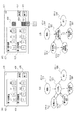
(形成されたプリント物の構造)
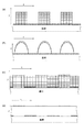
図4は、本実施例における画像形成装置にて形成する印刷物の構造の一例を示す模式図である。図4(a)は、xy二次元平面における凹凸データおよび色データを表している。x軸方向に凹部と凸部が交互に繰り返し配置されており、図4(a)において印刷面に正対してみると、いわゆる縦の万線パターンになっている。
(Structure of formed printed matter)
FIG. 4 is a schematic view showing an example of the structure of the printed matter formed by the image forming apparatus in this embodiment. FIG. 4A shows unevenness data and color data in the xy two-dimensional plane. The concave portions and the convex portions are alternately and repeatedly arranged in the x-axis direction, and when facing the printed surface in FIG. 4A, it is a so-called vertical universal line pattern.
図4(b)は、xz面における凹凸形状データ、すなわち図4(a)の断面構造を示している。本実施例では、プリンタ解像度が約600dpiであり、1ドットの幅は40μmとする。凸部が4ドット、凹部が4ドットの繰り返しであるため、凹凸1サイクルは320μmである。また、この例では、一層の厚さは15μmであり、凸部はz方向に10ドット積層して形成され、高さが150μmである。このような微小な凹凸層は、観察者からは視認されず、紙や布のような平面的な印刷物に見える。 FIG. 4B shows the uneven shape data on the xz plane, that is, the cross-sectional structure of FIG. 4A. In this embodiment, the printer resolution is about 600 dpi, and the width of one dot is 40 μm. Since the convex portion has 4 dots and the concave portion has 4 dots repeatedly, one cycle of unevenness is 320 μm. Further, in this example, the thickness of one layer is 15 μm, the convex portions are formed by laminating 10 dots in the z direction, and the height is 150 μm. Such a minute uneven layer is not visible to the observer and looks like a flat printed matter such as paper or cloth.
図4(c)は、(b)に示すデータを画像形成装置にて出力したプリント物の構造の一例を示す図である。図4(b)に示すデータを前述した図2に示す画像形成装置にてプリントすることで、図4(c)に示す形状が形成される。画像形成装置による凹凸形状の形成過程において、吐出されたUV硬化インクは、着弾からUV照射による硬化までの間、記録媒体の面方向に所謂、濡れ広がる。そのため、最終的に形成される凹凸形状は、図4(c)に示すように、図4(b)に示すデータ形状と比較して低周波な凹凸形状となる。なお、図4(c)に示す凹凸形状は一例であり、たとえば、濡れ広がりの度合いが低い高粘度のインクを用いることにより、より図4(a)に近い高周波な凹凸形状を形成することも可能である。 FIG. 4C is a diagram showing an example of the structure of a printed matter obtained by outputting the data shown in FIG. 4B by an image forming apparatus. By printing the data shown in FIG. 4B with the image forming apparatus shown in FIG. 2 described above, the shape shown in FIG. 4C is formed. In the process of forming the concave-convex shape by the image forming apparatus, the ejected UV-curable ink spreads in the surface direction of the recording medium from landing to curing by UV irradiation. Therefore, as shown in FIG. 4C, the finally formed uneven shape has a lower frequency than the data shape shown in FIG. 4B. The uneven shape shown in FIG. 4 (c) is an example. For example, by using a high-viscosity ink having a low degree of wetting and spreading, a high-frequency uneven shape closer to that of FIG. 4 (a) can be formed. It is possible.
図4(d)は、本実施例により形成されたプリント物により異方性が発現するメカニズムを説明するための模式図である。前述のようにプリント物は正確な矩形とはならないが、説明を簡易にするため、凹凸形状が矩形であるものとする。また、観察方向は、回転角θと仰角φで表現することができるが、本実施例では、回転角θは0°、すなわち、記録媒体表面をxy二次元平面とした際のx軸と並行であるものとする。また、仰角は、上記二次元平面の鉛直方向(法線)が成す角度をφ=0°とし、後述の入力処理における角度情報は、この値を用いる。 FIG. 4D is a schematic diagram for explaining the mechanism by which anisotropy is developed by the printed matter formed in this example. As described above, the printed matter does not have an accurate rectangle, but for the sake of simplicity, the uneven shape is assumed to be a rectangle. The observation direction can be expressed by a rotation angle θ and an elevation angle φ, but in this embodiment, the rotation angle θ is 0 °, that is, parallel to the x-axis when the surface of the recording medium is an xy two-dimensional plane. Suppose that. Further, as the elevation angle, the angle formed by the vertical direction (normal) of the two-dimensional plane is set to φ = 0 °, and this value is used for the angle information in the input processing described later.
まず、仰角φ=0°の場合、凸部の画像層と凹部の画像層との表面上の全領域について色を視認することができる。しかし、観察方向を変え、仰角φ=45°とした場合、凸部が凹部から上記法線方向に離れているため、凹部の一部が凸部により遮蔽され視認できなくなる。なお、凸部は遮蔽されることはない。 First, when the elevation angle φ = 0 °, the color can be visually recognized for the entire region on the surface of the convex image layer and the concave image layer. However, when the observation direction is changed and the elevation angle is φ = 45 °, since the convex portion is separated from the concave portion in the normal direction, a part of the concave portion is shielded by the convex portion and cannot be visually recognized. The convex portion is not shielded.
観察方向φで観察可能な単位面積あたりのインク量Vφは以下の式で表すことができる。 The amount of ink Vφ per unit area that can be observed in the observation direction φ can be expressed by the following equation.
ここで、Vtopは凸部の画像層の単位面積あたりのインク量、Vbotは凹部の画像層の単位面積あたりのインク量、aは凹凸1サイクルの幅、bは凸部の幅、cは凸部の高さを表す。式中の分母は、凹凸1サイクルを観察方向φから観察した面積と等しく、分子の第一項および第二項は、凸部の画像層と凹部の観察可能な画像層の面積比を表している。第二項のc・tan(φ)により遮蔽により観察できない面積を勘案している。なお、式中のa−b−c・tan(φ)がマイナスの場合は、遮蔽により凹部が見えない状態であるため、第二項は0とし、凸部のみが観察される。上記の式では、凸部の側面の露出が考慮されていない。しかし、通常は(c)に例示したように形状が鈍るため、上記の式で近似することが可能である。また、形状の鈍り、すなわち上述した濡れ広がりの特性により観察方向による遮蔽面積が大きく変わる場合は、予めプリンタの凹凸形成時の周波数応答特性などから補正量を求めておくことで、補正することが可能である。なお、遮蔽面積が大きく変わらない場合は、補正は不要である。
Here, Vtop is the amount of ink per unit area of the image layer of the convex portion, Vbot is the amount of ink per unit area of the image layer of the concave portion, a is the width of one cycle of unevenness, b is the width of the convex portion, and c is convex. Represents the height of the part. The denominator in the formula is equal to the area where one cycle of unevenness is observed from the observation direction φ, and the first and second terms of the numerator represent the area ratio of the image layer of the convex part and the observable image layer of the concave part. There is. The area that cannot be observed due to shielding is taken into consideration according to c · tan (φ) in the second term. When abc · tan (φ) in the equation is negative, the concave portion cannot be seen due to shielding, so the second term is set to 0 and only the convex portion is observed. In the above equation, the exposure of the side surface of the convex portion is not considered. However, since the shape is usually dull as illustrated in (c), it can be approximated by the above equation. In addition, if the shape is dull, that is, the shielding area varies greatly depending on the observation direction due to the above-mentioned wet spread characteristics, it can be corrected by obtaining the correction amount from the frequency response characteristics at the time of forming the unevenness of the printer in advance. It is possible. If the shielding area does not change significantly, no correction is required.
ここで、Fは遮蔽量を補正する関数である。補正にはルックアップテーブルLUTなどを利用することも可能である。
Here, F is a function for correcting the shielding amount. It is also possible to use a look-up table LUT or the like for the correction.
例えば、単純のため画像層はシアンインクのみ使うものとし、VtopがシアンインクC100%、VbotがC0%であるとする。a、b、cをそれぞれ図4(b)に例示したように、320μm、160μm、150μmとする。この時の観察方向φ=0°のVφは、遮蔽分tan(φ)=0となるため、式(1)より、 For example, for simplicity, it is assumed that only cyan ink is used for the image layer, Vtop is cyan ink C100%, and Vbot is C0%. As illustrated in FIG. 4B, a, b, and c are set to 320 μm, 160 μm, and 150 μm, respectively. At this time, Vφ in the observation direction φ = 0 ° has a shielding component tan (φ) = 0, so from equation (1),
つまり、Vφは、VtopとVbotが同じ面積で観察できるため、領域全体としては、シアンインクC50%として観察できる。
That is, since Vφ can be observed in the same area as Vtop and Vbot, the entire region can be observed as cyan ink C50%.
同様に、観察方向φ=45°のVφは、遮蔽分tan(φ)=1.0となり、式(1)より、 Similarly, Vφ in the observation direction φ = 45 ° has a shielding component tan (φ) = 1.0, and from the equation (1),
つまり、Vφは、シアンインクC 16/17≒94%として観察できる。すなわち、図4(c)に示すプリント物は、マクロの視点で観察すると、一見平面でありながら観察方向の仰角を変えると、シアンの濃淡が大きく変わる。このような見え方は、ベルベット生地のような質感を与える。
That is, Vφ can be observed as cyan ink C 16/17≈94%. That is, when the printed matter shown in FIG. 4C is observed from a macro perspective, the shade of cyan changes significantly when the elevation angle in the observation direction is changed even though it is seemingly flat. This appearance gives a velvet-like texture.
シアンインクのみを用いた場合の説明をしたが、一般的なプリンタで用いられるインク色であれば利用することが可能であり、凹部と凸部の観察可能な面積比を変えることで任意の異方性を再現することが可能である。例えば、凸部はシアンC100%、凹部はマゼンタM100%とすれば、観察方向に応じてブルーからマゼンタに変化する印刷物を形成することが可能になる。 The case where only cyan ink is used has been explained, but any ink color used in a general printer can be used, and any difference can be made by changing the observable area ratio of the concave portion and the convex portion. It is possible to reproduce the directionality. For example, if the convex portion is made of 100% cyan C and the concave portion is made of 100% magenta, it is possible to form a printed matter that changes from blue to magenta depending on the observation direction.
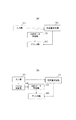
(画像形成装置の動作)
図5(a)は、実施例1における画像形成装置の機能構成を表すブロック図である。
(Operation of image forming device)
FIG. 5A is a block diagram showing a functional configuration of the image forming apparatus according to the first embodiment.
入力部101は、2つの観察方向とそれぞれの観察方向から画像を観察した際の色情報を画像データとして取得する。図6は、入力部101に入力される画像データの構成を表す模式図である。画像データは、任意の解像度であり、画素毎に、第一の観察方向φ1とその色情報Rφ1、Gφ1、Bφ1、第二の観察方向φ2とその色情報Rφ2、Gφ2、Bφ2が含まれている計8チャンネルのデータである。ここで、Rφ1、Gφ1、Bφ1およびRφ2、Gφ2、Bφ2は、sRGBで定義されるRGB値とする。他にも一般的に使用されているAdobeRGBで定義されるRGB画像や、CIELABに対応したLab画像などが利用できる。
The
画像データは、例えば、図に示す二つの幾何条件で対象物を撮影した画像をアフィン変換するなどして形状をそろえたものを利用することが可能である。この場合、二つの幾何条件が固定のため、φ1チャンネルには全画素に同じ値が、格納される。同様に、φ2チャンネルにも全画素に同じ値が格納される。こうした場合には、φ1、φ2の情報を画像データのヘッダ情報として保持するなどして、6チャンネルのデータとすることも可能である。入力部101は、色材量決定部103へ画像データを出力する。
As the image data, for example, it is possible to use data having the same shape by performing an affine transformation of an image obtained by photographing an object under the two geometric conditions shown in the figure. In this case, since the two geometric conditions are fixed, the same value is stored in all pixels in the φ1 channel. Similarly, the same value is stored in all pixels in the φ2 channel. In such a case, it is possible to obtain 6-channel data by holding the information of φ1 and φ2 as the header information of the image data. The
凹凸データ取得部102は、予めメモリなどに記憶されている凹凸データを取得し、色材量決定部103およびプリンタ部800へデータ出力する。ここで、凹凸データは、図4にて例示したようなx方向に凹凸を繰り返すパターンである。前述の通り、本実施例ではプリンタ解像度が約600dpiであり、1ドットの幅は40μmとし、凹凸データは、凸部幅4ドット、凹部幅4ドットである。
The unevenness
ここで、凹凸データの要件について説明する。前述の通り、本画像形成装置にて印刷物に異方性反射特性を発現させるためには、凸部の陰により凹部を隠す、いわゆるオクルージョンを利用することが必要である。画像形成装置にて凹凸層を形成する場合、画像形成装置の凹凸形成精度を要する。前述の通り、通常は形状の鈍りが発生し、この特性は周波数応答特性MTF(Modulation Transfer Function)として表現されることが広く知られている。MTF特性の典型的な例として、高周波成分の応答の劣化が挙げられる。これは、ある凹凸高低差を有する波形、例えば正弦波の入力があり、低周波では入力と同じ凹凸高低差が得られていても、周波数が上がるに従い凹凸高低差が低下していく現象である。凹凸高低差を得られなければ、凸部による陰が得られないため、本実施例で形成される凹凸は十分な応答が得られる周波数であることが必要である。本実施例で用いる凹凸データの周波数は75dpiであるため、例えば、画像形成装置の75dpiでのMTFが0.5以上であることが望まれる。なお、人間の視覚感度特性からより高周波なパターンほど目につきにくい。このため、画像形成装置のMTFが所定の値(例えば0.5)以上となる最も高周波なパターンを予めメモリなどに記憶しておき、凹凸データとして利用することが好ましい。 Here, the requirements for unevenness data will be described. As described above, in order for the image forming apparatus to exhibit anisotropic reflection characteristics in printed matter, it is necessary to use so-called occlusion in which the concave portion is hidden by the shadow of the convex portion. When forming the uneven layer with the image forming apparatus, the unevenness forming accuracy of the image forming apparatus is required. As described above, it is widely known that the shape is usually dull and this characteristic is expressed as a frequency response characteristic MTF (Modulation Transfer Function). A typical example of MTF characteristics is deterioration of the response of high frequency components. This is a phenomenon in which there is an input of a waveform having a certain unevenness height difference, for example, a sine wave, and even if the same unevenness height difference as the input is obtained at a low frequency, the unevenness height difference decreases as the frequency increases. .. If the difference in height of the unevenness cannot be obtained, the shadow due to the convex portion cannot be obtained. Therefore, the unevenness formed in this embodiment needs to have a frequency at which a sufficient response can be obtained. Since the frequency of the unevenness data used in this embodiment is 75 dpi, it is desirable that the MTF of the image forming apparatus at 75 dpi is 0.5 or more, for example. Due to human visual sensitivity characteristics, higher frequency patterns are less noticeable. Therefore, it is preferable to store the highest frequency pattern in which the MTF of the image forming apparatus is at least a predetermined value (for example, 0.5) in a memory or the like in advance and use it as unevenness data.
また、凸部による陰を発生させるための凸部の高さについて説明する。例えば、観察方向φ=0°からφ=45°で大きな色の変化を得るには、φ=45°で凹部が完全に見えなくなればよいので、凸部の高さは、凹部幅以上であることが望ましい。凸部の高さが凹部幅より低くても遮蔽領域があれば異方性を発現できるが、高さが低くなるほど観察方向による色の差、すなわち異方性が弱くなる。 In addition, the height of the convex portion for generating the shadow due to the convex portion will be described. For example, in order to obtain a large color change from φ = 0 ° to φ = 45 ° in the observation direction, it is sufficient that the concave portion is completely invisible at φ = 45 °, so that the height of the convex portion is equal to or greater than the concave width. Is desirable. Even if the height of the convex portion is lower than the width of the concave portion, anisotropy can be exhibited if there is a shielding region, but the lower the height, the weaker the color difference depending on the observation direction, that is, the anisotropy.
色材量決定部103は、入力部101からの画像データと凹凸データ取得部102から凹凸データを受け取る。色情報は凹凸1セットに対して、二つの観察方向と二つの色情報が与えられる。このため、画像データはx方向解像度600/8=75dpi、y方向解像度600dpiに変換される。解像度変換により高い解像度の複数の観察方向φを低い解像度へ変換する際は、単純に各方向の単位ベクトルの平均を求めればよい。逆に低い解像度から高い解像度に変換する場合は、一般的なニアレストネイバー法などを用いればよい。色情報の解像度変換処理は、プリンタで用いられている一般的な方法が利用できるため、説明を省略する。さらに、色材量決定部103は、入力された凹凸データと画像データから、凹部と凸部に対応するインク量を算出する。算出されたインク量は、プリンタ解像度で規定される各画素のCMYKインク量に変換され、プリンタ部へ送信される。インク量算出の詳細については後述する。
The color material
プリンタ部800は、凹凸データ取得部102から凹凸データを受け取った凹凸データをもとにクリアインクを用いて凹凸層を形成する。また、プリンタ部800は、色材量決定部103から受け取った各画素のCMYKインク量に基づき、先に形成された凹凸層上に画像層を形成する。
The
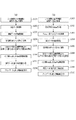
図7(a)は、実施例1の画像形成装置が出力物を形成するまでの流れを示すフローチャートである。 FIG. 7A is a flowchart showing a flow until the image forming apparatus of the first embodiment forms an output.
まず、ステップS201において、入力部102は2つの観察方向とそれぞれの観察方向から観察した際の色情報を画像データとして取得する。
First, in step S201, the
次に、ステップS202において、凹凸データ取得部102は、凹凸データを取得し、色材量決定部103およびプリンタ部800へ送信する。
Next, in step S202, the unevenness
次に、ステップS203において、色材量決定部103は、画像データを凹凸データの周期に基づく解像度に変換する。
Next, in step S203, the color material
次に、ステップS204において、色情報Rφ1、Gφ1、Bφ1とRφ2、Gφ2、Bφ2をそれぞれCMYKインク値Vφ1とVφ2に変換する。RGBからCMYKへの変換は一般的に使われているLUTを使った変換方法などが利用できる。 Next, in step S204, the color information Rφ1, Gφ1, Bφ1 and Rφ2, Gφ2, and Bφ2 are converted into CMYK ink values Vφ1 and Vφ2, respectively. For the conversion from RGB to CMYK, a commonly used conversion method using a LUT or the like can be used.
次に、ステップS205において、インク値Vφ1およびVφ2と観察方向φ1およびφ2から凸部インク量Vtopおよび凹部インク量Vbotを算出する。VtopおよびVbotは、式(1)を用いた連立方程式で算出することができる。ステップS204にて算出されたVφ1と観察方向φ1を式(1)のVφとφへ代入する。同様に算出されたVφ2と観察方向φ2を式(1)のVφとφへ代入する。上記二つを連立方程式として解くことで凸部インク量Vtopおよび凹部インク量Vbotが算出される。 Next, in step S205, the convex ink amount Vtop and the concave ink amount Vbot are calculated from the ink values Vφ1 and Vφ2 and the observation directions φ1 and φ2. Vtop and Vbot can be calculated by simultaneous equations using the equation (1). Substitute Vφ1 and the observation direction φ1 calculated in step S204 into Vφ and φ in the equation (1). Substituting Vφ2 and the observation direction φ2 calculated in the same manner into Vφ and φ in the equation (1). By solving the above two as simultaneous equations, the convex ink amount Vtop and the concave ink amount Vbot are calculated.
ここで、算出した凸部インク量Vtopおよび凹部インク量Vbotは、CMYKのインク値Ctop、Mtop、Ytop、Ktop、Cbot、Mbot、Ybot、Kbotから構成される。各CMYKインク値は通常0%から100%の範囲で利用される。しかし、上記連立方程式の解が0未満もしくは100より大きい場合がある。これは、CMYKインク値0%から100%の範囲では、入力された観察方向と色情報を満たす印刷物を得ることができないことを示している。例えば、正対した際に、すなわちφ=0°で白に、斜めから見た際に黒に見える印刷物は、本実施例のプリント構造では得ることができない。こうした場合は、0%未満の値を0%へ、100%より大きい値を100%へ、所謂丸める処理を入れることで、所望の特性に近い印刷物を得ることが可能である。なお、画像層の形成において、CMYKの各インクを100%より大きく載せることが可能な場合は、100%への丸め処理は不要である。また、解が0%から100%の範囲から著しく外れている場合は、入力条件を満たせない旨をユーザに知らせ画像形成処理を終了するなどの方法も考えられる。 Here, the calculated convex ink amount Vtop and concave ink amount Vbot are composed of CMYK ink values Ctop, Mtop, Ytop, Ktop, Cbot, Mbot, Ybot, and Kbot. Each CMYK ink value is usually used in the range of 0% to 100%. However, the solution of the simultaneous equations may be less than 0 or greater than 100. This indicates that it is not possible to obtain a printed matter satisfying the input observation direction and color information in the range of 0% to 100% of the CMYK ink value. For example, a printed matter that looks white when facing each other, that is, when φ = 0 ° and black when viewed from an angle, cannot be obtained with the printed structure of the present embodiment. In such a case, it is possible to obtain a printed matter having desired characteristics by adding a so-called rounding process in which a value less than 0% is reduced to 0% and a value larger than 100% is reduced to 100%. In forming the image layer, if it is possible to place each CMYK ink larger than 100%, the rounding process to 100% is unnecessary. Further, when the solution is significantly out of the range of 0% to 100%, a method of notifying the user that the input condition cannot be satisfied and ending the image forming process can be considered.
次に、ステップS206において、凸部インク量Vtopおよび凹部インク量Vbotをプリンタ解像度に変換し、画像層形成用のプリントデータとしてプリント部800へ送信する。
Next, in step S206, the convex ink amount Vtop and the concave ink amount Vbot are converted into printer resolutions and transmitted to the
次に、ステップS207において、プリント部800は凹凸データに基づいて凹凸層を形成する。
Next, in step S207, the printed
次に、ステップS208において、プリント部800は画像層形成用プリントデータに基づいて画像層を形成する。
Next, in step S208, the
以上により、図4に例示した構造の印刷物を形成することが可能であり、形成された印刷物は所望の異方性反射を発現することが可能である。 As described above, it is possible to form a printed matter having the structure illustrated in FIG. 4, and the formed printed matter can exhibit a desired anisotropic reflection.
以上説明したように本実施例の画像形成装置は、印刷物の凹凸と色を制御することで異方性を有する印刷物を得ることが可能である。 As described above, the image forming apparatus of this embodiment can obtain a printed matter having anisotropy by controlling the unevenness and color of the printed matter.
なお、本実施例においては、先に凹凸層を形成し、その後、凹凸層上に画像層を形成すると記載した。この際、画像形成装置の印字位置の精度、つまり着弾精度によっては、凹部と凸部に精度よく画像層を形成することができず、所望の結果を得られない場合がある。こうした場合、本実施例で算出した凹部インク量にて、メディア全面に第一の画像層を形成し、この後に凹凸層、凸部画像層を形成する方法も考えられる。図11(a)は、前記方法における凹凸データおよび色データの関係を示す模式図、図11(b)は、形成される印刷物の断面のイメージ図である。こうすることで、少なくとも凹凸層と凹部画像層の相対的な位置精度を無視でき、且つ同様の効果を得ることが可能になる。また、凸部画像層の光透過性が高く、下層画像層の影響を大きく受ける場合は、凹凸層形成時にクリアインクに変わってホワイトインクを用いることでも同様の効果を得ることができる。これは、ホワイトインクの光透過性が一般的に低く、下層の影響を受けにくいためである。また、画像層形成時の色インク量の算出は、通常、白色の印字メディアが下地であることを想定したものであるため、他の色インクで凹凸層を形成するよりホワイトインクで形成した方が、発色の変化が少ないためである。画像層を形成する色インクの透過性が低く、発色に下地の影響を受けない画像層が形成できるインクであれば、凹凸層を形成するインクは、クリアインクやホワイトインクに限られない。 In this embodiment, it is described that the uneven layer is formed first, and then the image layer is formed on the uneven layer. At this time, depending on the accuracy of the printing position of the image forming apparatus, that is, the landing accuracy, the image layer may not be formed accurately in the concave portion and the convex portion, and a desired result may not be obtained. In such a case, a method of forming the first image layer on the entire surface of the medium with the concave ink amount calculated in this embodiment and then forming the uneven layer and the convex image layer can be considered. FIG. 11A is a schematic view showing the relationship between the unevenness data and the color data in the method, and FIG. 11B is an image view of a cross section of the printed matter to be formed. By doing so, at least the relative positional accuracy between the uneven layer and the concave image layer can be ignored, and the same effect can be obtained. Further, when the convex image layer has high light transmittance and is greatly affected by the lower image layer, the same effect can be obtained by using white ink instead of clear ink when forming the uneven layer. This is because the light transmittance of the white ink is generally low and it is not easily affected by the lower layer. In addition, since the calculation of the amount of color ink at the time of forming the image layer is usually based on the assumption that the white print medium is the base, it is better to use white ink than to form the uneven layer with other color inks. However, this is because there is little change in color development. The ink that forms the concavo-convex layer is not limited to clear ink and white ink, as long as the color ink that forms the image layer has low transparency and can form an image layer that is not affected by the background color.
さらに、凹凸層の高低差を設けず、印刷物表面をほぼ平面にして同様の効果を得る構造も考えられる。図11(c)はメディア表面の一部に第一の画像層を形成し、その上のクリアインクにて一定の厚みを持った凹凸層を形成し、さらに凹凸層上部の一部に第二の画像層を形成した例である。また(d)はその断面構造の一例の模式図である。この例では、観察方向の変化に応じて、上部画像層と下部画像層と基材であるメディアの3つの面積比率が変わる。これにより異方性を有する印刷物を得ることが可能である。 Further, a structure in which the height difference of the uneven layer is not provided and the surface of the printed matter is made substantially flat to obtain the same effect can be considered. In FIG. 11C, a first image layer is formed on a part of the surface of the media, an uneven layer having a certain thickness is formed on the clear ink on the image layer, and a second image layer is formed on a part of the upper part of the uneven layer. This is an example of forming the image layer of. Further, (d) is a schematic view of an example of the cross-sectional structure. In this example, the three area ratios of the upper image layer, the lower image layer, and the medium as the base material change according to the change in the observation direction. This makes it possible to obtain a printed matter having anisotropy.
なお、ステップS205のインク量算出処理において、0%未満の値を0%へ、100%より大きい値を100%へ丸める処理を記載した。この処理の代わりに、ステップS202へ戻り凹部と凸部の面積比の異なるパターンを用いることで、入力条件を満たす凹凸およびインク色データを作成することも可能である。 In the ink amount calculation process of step S205, a process of rounding a value less than 0% to 0% and a value larger than 100% to 100% is described. Instead of this process, it is possible to return to step S202 and create unevenness and ink color data satisfying the input conditions by using patterns having different area ratios of the concave portion and the convex portion.
また、プリント部の例としてUV硬化型インクジェット方式を例に挙げたが、算出した凹凸データとプリントデータに応じて、凹凸層および画像層を形成できるものであれば構わない。 Further, although the UV curable inkjet method is taken as an example of the printed portion, any one that can form the concave-convex layer and the image layer according to the calculated unevenness data and the print data may be used.
また、式(1)を用いたインク量算出において、観察時の光源は全方位の拡散光を想定して記載しているが、特定方向からの光を考慮し、凸部と凹部のインク量に補正係数を掛けてもよい。 Further, in the calculation of the ink amount using the equation (1), the light source at the time of observation is described assuming diffused light in all directions, but the ink amount of the convex portion and the concave portion is described in consideration of the light from a specific direction. May be multiplied by a correction coefficient.
実施例1において形成する凹凸層は、あらかじめ設定した固定のパターン、例えば、縦万線パターンで配置された溝構造であるものとして説明した。本実施例では、入力された観察方向に基づき凹凸パターンを形成することで、異方性を発現する印刷物を得る方法について記載する。なお、本実施例における画像形成装置の構成および動作は、特に説明のない限り実施例1に示したものと同じである場合は省略する。 The uneven layer formed in the first embodiment has been described as having a groove structure arranged in a fixed pattern set in advance, for example, a vertical universal line pattern. In this embodiment, a method of obtaining a printed matter exhibiting anisotropy by forming an uneven pattern based on an input observation direction will be described. Unless otherwise specified, the configuration and operation of the image forming apparatus in this embodiment will be omitted if they are the same as those shown in Example 1.
図5(b)は、本実施例における画像形成装置の機能構成を表すブロック図である。 FIG. 5B is a block diagram showing a functional configuration of the image forming apparatus in this embodiment.
入力部101’は、2つの観察方向とそれぞれの観察方向から画像を観察した際の色情報を画像データとして取得する。実施例1では、観察方向を回転角θは0°固定で仰角φのみを指定するものとして説明した。本実施例では、観察方向を回転角θおよび仰角φの二つのパラメータとして入力する。色情報については実施例1と同じである。 The input unit 101'acquires color information when observing an image from two observation directions and each observation direction as image data. In the first embodiment, the observation direction is described as assuming that the rotation angle θ is fixed at 0 ° and only the elevation angle φ is specified. In this embodiment, the observation direction is input as two parameters of rotation angle θ and elevation angle φ. The color information is the same as in the first embodiment.
ベクトル演算部104’は、入力部101から二つの観察方向を受け取り、後に形成する凹凸データの方向性θshapeを決定する。本実施例でも実施例1と同様に凹凸の陰を利用して、異方性を発現させる。このため、周辺領域に少なくとも2サイクル以上の複数の凹凸が繰り返し配置されていることが望ましい。そこで、ベクトル演算部104’は、後述の凹凸データ取得部103’で利用する各方向の凹凸パターンの周期に応じた解像度で凹凸方向性θshapeを設定する。例えば、凹凸データ取得部103’で利用する各凹凸パターンの周期がプリンタ解像度にて8pixelであれば、xyともに600/(8×2)=37.5dpiの凹凸方向性θshapeの画像データを生成する。観察方向の解像度変換については実施例1と同様に二次元の単位ベクトル(θ、φ)の平均を求めればよい。本実施例では、凹凸方向性算出をθshape=(θ1+θ2)/2とする。これは、観察方向1(θ1、φ1)から観察方向2(θ2、φ2)に視点が移動した際に、陰の変化量が大きく変化し、大きな異方性を発現させるためである。ベクトル演算部104’は、算出した凹凸方向性θshapeを凹凸データ取得部102’に送信する。
The vector calculation unit 104'receives two observation directions from the
凹凸データ取得部102’は、予めメモリなどに記憶してある複数の方向性を持った凹凸データから、受け取った画素毎の凹凸方向性θshapeに近い方向性の凹凸データを取得し、色材量決定部103’へ送信する。 The unevenness data acquisition unit 102'acquires the unevenness data having a plurality of directions stored in a memory or the like in advance, and acquires the unevenness data having a direction close to the unevenness direction θshape for each received pixel, and the amount of coloring material. It is transmitted to the determination unit 103'.
色材量決定部103’は、入力部101’からの画像データと凹凸データ取得部102’からの凹凸データに基づき、実施例1と同様に凹凸周期毎に凹部と凸部のCMYKインク量を算出し、プリンタ部800へ送信する。
Based on the image data from the input unit 101'and the unevenness data from the unevenness data acquisition unit 102', the color material amount determining unit 103'sets the CMYK ink amount of the concave and convex parts for each unevenness cycle as in the first embodiment. It is calculated and transmitted to the
図7(b)は、本実施例の画像形成装置が出力物を形成するまでの流れを示すフローチャートである。 FIG. 7B is a flowchart showing a flow until the image forming apparatus of this embodiment forms an output.
まず、ステップS301において、入力部102は2つの観察方向とそれぞれの観察方向から観察した際の色情報を画像データとして取得し、ベクトル演算部104’へ観察方向データを、色材量決定部103’へ色情報データを送信する。
First, in step S301, the
次に、ステップS302において、ベクトル演算部104’は、2つの観察方向データに基づき凹凸方向性θspaheを算出する。 Next, in step S302, the vector calculation unit 104'calculates the unevenness direction θspahe based on the two observation direction data.
次に、ステップS303において、凹凸データ取得部102は、凹凸方向性θspaheに基づき凹凸データを取得し、色材量決定部103’およびプリンタ部800へ送信する。
Next, in step S303, the unevenness
次に、ステップS304において、色材量決定部103’は、画像データを凹凸データの周期に基づく解像度に変換する。 Next, in step S304, the color material amount determining unit 103'converts the image data into a resolution based on the period of the uneven data.
次に、ステップS305において、色情報Rφ1、Gφ1、Bφ1とRφ2、Gφ2、Bφ2をそれぞれCMYKインク値Vφ1とVφ2に変換する。 Next, in step S305, the color information Rφ1, Gφ1, Bφ1 and Rφ2, Gφ2, and Bφ2 are converted into CMYK ink values Vφ1 and Vφ2, respectively.
次に、ステップS306において、凸部インク量Vtopおよび凹部インク量Vbotをプリンタ解像度に変換し、画像層形成用のプリントデータとしてプリント部800へ送信する。
Next, in step S306, the convex ink amount Vtop and the concave ink amount Vbot are converted into printer resolution and transmitted to the
次に、ステップS307において、プリント部800は凹凸データに基づいて凹凸層を形成する。
Next, in step S307, the printed
次に、ステップS308において、プリント部800は画像層形成用プリントデータに基づいて画像層を形成する。
Next, in step S308, the
図8は、本実施例にて得られる凹凸パターンの一例を示す。 FIG. 8 shows an example of the unevenness pattern obtained in this embodiment.
以上説明したように、入力された画素毎の二つの観察方向に基づき、凹凸方向性を設定することで、領域毎に異方性反射特性の方向性の異なる印刷物を得ることができる。 As described above, by setting the unevenness directionality based on the two observation directions for each input pixel, it is possible to obtain printed matter having different directions of anisotropic reflection characteristics for each region.
実施例1および実施例2において、異方性反射特性を有する印刷物の形成方法について説明した。本実施例では、印刷物の形成におけるパラメータを設定するためのユーザインターフェースについて記載する。 In Examples 1 and 2, a method for forming a printed matter having anisotropic reflection characteristics has been described. In this embodiment, a user interface for setting parameters in the formation of printed matter will be described.
<ユーザインターフェ−ス1>
実施例1にて説明したフローチャートのステップS201において、画像データの入力のかわりに、ユーザインターフェースを使ったパラメータの指定方法について説明する。
<
In step S201 of the flowchart described in the first embodiment, a method of specifying parameters using a user interface instead of inputting image data will be described.
モニタ900は、画像処理を行うために必要な情報をユーザに入力してもらうためのユーザインタフェースを表示する。図9(a)にユーザインタフェースの例を示す。
The
指示入力部402は、第1目標色の色情報ならびに角度を指示入力する。指示入力部403は、第2目標色の色情報ならびに角度を指示入力する。設定ボタン404は、目標色の設定を決定するためのボタンである。終了ボタン405は終了に関する動作を実行しUIを閉じる。
The
以下に図9(b)の状態遷移図を用いてUIの状態遷移について説明する。なお目標色設定処理については後述する
ステート501では初期化を行った後、ユーザインターフェース401を表示しステート502へ遷移するとともにユーザの入力待ちになる。
The state transition of the UI will be described below using the state transition diagram of FIG. 9B. Regarding the target color setting process, after the
ステート502では、指示入力部402、指示入力部403にユーザからの指示が入力されるとステート503へ遷移する。ユーザによって設定ボタン404が押下されるとステート504へ遷移し目標色が再現可能かの判定を行う。さらに再現可能な場合はステート501へ、再現可能でない場合はステート505へ遷移する。ステート505では第2目標色を変更しステート501へ遷移する。ユーザによって終了ボタン405が押下されるとステート506へ遷移する。
In the
以下では図10(a)のフローチャートを用いて目標色設定処理について説明する。 Hereinafter, the target color setting process will be described with reference to the flowchart of FIG. 10A.
ステップS601において、指示入力部402から指示入力された第1目標色C1、指示入力部403から指示入力された第2目標色C2と、画像形成装置の色再現情報を取得する。
In step S601, the first target color C1 instructed and input from the
ステップS602において、ベクトルC1C2と色再現外郭色Cmを求める。 In step S602, the vector C1C2 and the color reproduction outline color Cm are obtained.
ステップS603において、次式(5)によりスカラーC1C2とスカラーC1Cm/2の大きさを比較し、条件を満たしていなければステップS604へそうでなければ終了に関する動作を行う。 In step S603, the sizes of the scalar C1C2 and the scalar C1Cm / 2 are compared by the following equation (5), and if the conditions are not satisfied, the operation for ending is performed in step S604.
ステップS604において、次式によりC2のLab値を算出しメモリに記憶するとともに終了に関する動作を行う。
In step S604, the Lab value of C2 is calculated by the following equation, stored in the memory, and the operation related to the end is performed.
<ユーザインターフェ−ス2>
モニタ900は、画像処理を行うために必要な情報をユーザに入力してもらうためのユーザインタフェースを表示する。図9(c)にユーザインタフェースの例を示す。
<
The
指示入力部402’は、第1目標色の色情報ならびに角度を指示入力する。表示部403’は、選択されている第2目標色の色情報を表示する。ウィンドウ404’は第1目標色に相当する色票を表示する。ウィンドウ405’は第2目標色として選択された色票を表示する。設定ボタン406’は、目標色の設定を決定するためのボタンである。終了ボタン407’は終了に関する動作を実行しUIを閉じる。 The instruction input unit 402'instructs and inputs the color information and the angle of the first target color. The display unit 403'displays the color information of the selected second target color. Window 404'displays a color tag corresponding to the first target color. Window 405'displays the color tag selected as the second target color. The setting button 406'is a button for determining the setting of the target color. The end button 407'executes the operation related to the end and closes the UI.
以下に図9(d)の状態遷移図を用いてUIの状態遷移について説明する。なお目標色設定処理については後述する
ステート501’では初期化を行った後、ユーザインターフェース401’を表示しステート502’へ遷移するとともにユーザの入力待ちになる。
The state transition of the UI will be described below using the state transition diagram of FIG. 9D. The target color setting process is initialized in the state 501', which will be described later, and then the user interface 401'is displayed to transition to the state 502'and waits for the user's input.
ステート502’では、指示入力部402’にユーザからの指示が入力されるとステート503’へ遷移する。ウィンドウ405’の色票が変更されるとステート505’に遷移する。ステート505’では第2目標色を変更しステート501’へ遷移する。ユーザによって設定ボタン406’が押下されると目標色を記憶する。ユーザによって終了ボタン405’が押下されるとステート506’へ遷移する。 In the state 502', when an instruction from the user is input to the instruction input unit 402', the state transitions to the state 503'. When the color tag of window 405'is changed, the state transitions to state 505'. In the state 505', the second target color is changed and the state transitions to the state 501'. When the setting button 406'is pressed by the user, the target color is stored. When the end button 405'is pressed by the user, the state transitions to the state 506'.
以下では図10(b)のフローチャートを用いて目標色設定処理について説明する。 Hereinafter, the target color setting process will be described with reference to the flowchart of FIG. 10B.
ステップS601’において、指示入力部402’から指示入力された第1目標色C1、画像形成装置の色再現情報を取得する。 In step S601', the first target color C1 instructed and input from the instruction input unit 402' and the color reproduction information of the image forming apparatus are acquired.
ステップS602’において、色再現情報の格子点のうち最外郭の色Ck(k=1〜n)と目標色C1の中点Ck’を求める。
ステップS603’において、全ての最外郭の格子点について目標色C1との中点を算出していればステップS604’へ、そうでなければステップS602’へジャンプする。
In step S602', the outermost color Ck (k = 1 to n) and the midpoint Ck'of the target color C1 among the grid points of the color reproduction information are obtained.
In step S603', if the midpoint with the target color C1 is calculated for all the outermost grid points, the process jumps to step S604', otherwise the process jumps to step S602'.
ステップS604’において、色再現情報の各格子点についてCk’で構成される色領域の内外判定を行い、内側あればステップS605’へそうでなければステップS6へ進む。 In step S604', each grid point of the color reproduction information is determined to be inside or outside the color region composed of Ck', and if it is inside, the process proceeds to step S605', otherwise the process proceeds to step S6.
ステップS605’において、格子点に相当する色票をウィンドウ405’に追加する。 In step S605', a color tag corresponding to the grid points is added to the window 405'.
ステップS606’において、全ての格子点情報について処理を行っていれば終了に関する動作を行い、そうでなければステップS604’へジャンプする。 In step S606', if all the grid point information is processed, the operation related to the end is performed, and if not, the process jumps to step S604'.
なお、補正後の第2の目標色について、第1目標色と最外郭の中点を用いたが式1を満たす範囲であればその中間の色を用いてもかまわないのはいうまでも無い。
As for the corrected second target color, the first target color and the midpoint of the outermost shell are used, but it goes without saying that an intermediate color may be used as long as the range satisfies
また、目標色候補を表示する一例として色票を用いたが、これに限定されるものではなくカラーホイール等の表示を用いても良いことは言うまでも無い。 Further, although the color tag is used as an example of displaying the target color candidate, it is needless to say that the display is not limited to this and a display such as a color wheel may be used.
以上、説明したインターフェースを用いることで、ユーザが画像形成装置の特性を把握していない場合でも、簡易に目標色を設定することができる。 By using the interface described above, the target color can be easily set even when the user does not understand the characteristics of the image forming apparatus.
Claims (11)
前記印刷物を第1観察方向から観察した場合に視認される第1色を表す第1色情報を取得する第1取得手段と、
前記印刷物を前記第1観察方向とは異なる第2観察方向から観察した場合に視認され、前記第1色とは異なる第2色を表す第2色情報を取得する第2取得手段と、
前記印刷物を前記第1観察方向から観察した場合に前記第1色が視認され、前記印刷物を前記第2観察方向から観察した場合に前記第2色が視認されるように、前記凹凸の凹部の上に記録する第1色材量と前記凹凸の凸部の上に記録する第2色材量とを決定する決定手段と、を有し、
前記第1色と前記第2色との少なくとも一方は、前記第1色材量の色材が記録された前記凹部の色と、前記第2色材量の色材が記録された前記凸部の色と、の混色により表現されることを特徴とする画像処理装置。 An image processing device that determines the amount of the color material in order to form a printed matter in which different colors are visually recognized when observed from different directions by recording the color material on the unevenness on the print medium. ,
A first acquisition means for acquiring first color information representing a first color that is visually recognized when the printed matter is observed from the first observation direction.
A second acquisition means for acquiring second color information that is visually recognized when the printed matter is observed from a second observation direction different from the first observation direction and represents a second color different from the first color.
The concave and convex recesses so that the first color is visually recognized when the printed matter is observed from the first observation direction, and the second color is visually recognized when the printed matter is observed from the second observation direction. It has a determining means for determining the amount of the first color material to be recorded above and the amount of the second color material to be recorded on the convex portion of the unevenness.
At least one of the first color and the second color is the color of the recess in which the color material of the first color material is recorded and the convex portion in which the color material of the second color material is recorded. An image processing device characterized in that it is expressed by mixing the colors of.
前記決定手段は、さらに前記データに基づいて、前記第1色材量と前記第2色材量とを決定することを特徴とする請求項1乃至請求項4のいずれか一項に記載の画像処理装置。 Further having a third acquisition means for acquiring data representing the height of the unevenness,
Said determining means is further based on said data, the image according to any one of claims 1 to 4, characterized in that determining said second color material amount and the first color material amount Processing equipment.
前記第2取得手段は、さらに、前記第2観察方向を取得し、
前記決定手段は、さらに前記第1観察方向と前記第2観察方向とに基づいて、前記第1色材量と前記第2色材量とを決定することを特徴とする請求項1乃至請求項5のいずれか一項に記載の画像処理装置。 The first acquisition means further acquires the first observation direction.
The second acquisition means further acquires the second observation direction.
Said determining means further wherein the first viewing direction based on the second observation direction, claims 1 and determines the second color material amount and the first color material amount 5. The image processing apparatus according to any one of 5 .
前記印刷物を第1観察方向から観察した場合に視認される第1色を表す第1色情報を取得する第1取得工程と、
前記印刷物を前記第1観察方向とは異なる第2観察方向から観察した場合に視認され、前記第1色とは異なる第2色を表す第2色情報を取得する第2取得工程と、
前記印刷物を前記第1観察方向から観察した場合に前記第1色が視認され、前記印刷物を前記第2観察方向から観察した場合に前記第2色が視認されるように、前記凹凸の凹部の上に記録する第1色材量と前記凹凸の凸部の上に記録する第2色材量とを決定する決定工程と、を有し、
前記第1色と前記第2色との少なくとも一方は、前記第1色材量の色材が記録された前記凹部の色と、前記第2色材量の色材が記録された前記凸部の色と、の混色により表現されることを特徴とする画像処理方法。 An image processing method for determining the amount of the color material in order to form a printed matter in which different colors are visually recognized when observed from different directions by recording the color material on the unevenness on the print medium. ,
The first acquisition step of acquiring the first color information representing the first color visually recognized when the printed matter is observed from the first observation direction, and
A second acquisition step of acquiring second color information representing a second color different from the first color, which is visually recognized when the printed matter is observed from a second observation direction different from the first observation direction.
The concave and convex recesses so that the first color is visually recognized when the printed matter is observed from the first observation direction, and the second color is visually recognized when the printed matter is observed from the second observation direction. It has a determination step of determining the amount of the first color material to be recorded above and the amount of the second color material to be recorded on the convex portion of the unevenness.
At least one of the first color and the second color is the color of the recess in which the color material of the first color material is recorded and the convex portion in which the color material of the second color material is recorded. An image processing method characterized in that it is expressed by mixing the colors of.
Priority Applications (10)
| Application Number | Priority Date | Filing Date | Title |
|---|---|---|---|
| JP2015177011A JP6765794B2 (en) | 2015-09-08 | 2015-09-08 | Image processing equipment, image processing methods, and programs |
| KR1020187009504A KR20180050694A (en) | 2015-09-08 | 2016-09-05 | Printed matter, image processing apparatus, image processing method, and program |
| EP16843933.9A EP3347205A4 (en) | 2015-09-08 | 2016-09-05 | Print product, image processing apparatus, image processing method, and program |
| CN201680052181.XA CN108025557B (en) | 2015-09-08 | 2016-09-05 | Print product, image processing apparatus, image processing method, and computer-readable storage medium |
| BR112018004367-2A BR112018004367B1 (en) | 2015-09-08 | 2016-09-05 | PRINTING PRODUCT, IMAGE PROCESSING APPARATUS,IMAGE PROCESSING METHOD AND PROGRAM |
| US15/757,319 US20180264838A1 (en) | 2015-09-08 | 2016-09-05 | Print product, image processing apparatus, image processing method, and program |
| RU2018112468A RU2689881C1 (en) | 2015-09-08 | 2016-09-05 | Printed product, image processing device and image processing method |
| PCT/JP2016/004031 WO2017043065A1 (en) | 2015-09-08 | 2016-09-05 | Print product, image processing apparatus, image processing method, and program |
| US16/831,155 US11312153B2 (en) | 2015-09-08 | 2020-03-26 | Print product, image processing apparatus, image processing method, and program |
| US17/711,967 US11912042B2 (en) | 2015-09-08 | 2022-04-01 | Print product, image processing apparatus, image processing method, and program |
Applications Claiming Priority (1)
| Application Number | Priority Date | Filing Date | Title |
|---|---|---|---|
| JP2015177011A JP6765794B2 (en) | 2015-09-08 | 2015-09-08 | Image processing equipment, image processing methods, and programs |
Publications (3)
| Publication Number | Publication Date |
|---|---|
| JP2017052154A JP2017052154A (en) | 2017-03-16 |
| JP2017052154A5 JP2017052154A5 (en) | 2018-12-06 |
| JP6765794B2 true JP6765794B2 (en) | 2020-10-07 |
Family
ID=58240762
Family Applications (1)
| Application Number | Title | Priority Date | Filing Date |
|---|---|---|---|
| JP2015177011A Active JP6765794B2 (en) | 2015-09-08 | 2015-09-08 | Image processing equipment, image processing methods, and programs |
Country Status (8)
| Country | Link |
|---|---|
| US (3) | US20180264838A1 (en) |
| EP (1) | EP3347205A4 (en) |
| JP (1) | JP6765794B2 (en) |
| KR (1) | KR20180050694A (en) |
| CN (1) | CN108025557B (en) |
| BR (1) | BR112018004367B1 (en) |
| RU (1) | RU2689881C1 (en) |
| WO (1) | WO2017043065A1 (en) |
Families Citing this family (10)
| Publication number | Priority date | Publication date | Assignee | Title |
|---|---|---|---|---|
| JP6891011B2 (en) * | 2016-06-30 | 2021-06-18 | キヤノン株式会社 | Image processing equipment, image processing methods and programs |
| JP6855293B2 (en) * | 2016-06-30 | 2021-04-07 | キヤノン株式会社 | Image processing equipment, image processing methods and programs |
| JP6900239B2 (en) | 2017-05-31 | 2021-07-07 | キヤノン株式会社 | Image processing equipment, image processing methods and programs |
| EP3498479B1 (en) * | 2017-12-18 | 2023-06-07 | Canon Production Printing Holding B.V. | A method for printing swaths of an image on a substrate |
| EP3579535B1 (en) * | 2018-06-06 | 2022-03-23 | Canon Production Printing Holding B.V. | Method of constructing a preview of an elevated lenticular print |
| JP7316829B2 (en) * | 2019-04-15 | 2023-07-28 | キヤノン株式会社 | Information processing device, information processing method, and program |
| JP7054966B2 (en) * | 2019-07-23 | 2022-04-15 | 孝司 浅尾 | Manufacturing method of viewing angle change printed matter, viewing angle changing printed matter, and printing method of viewing angle changing printed matter |
| JP7336536B2 (en) | 2019-11-27 | 2023-08-31 | 富士フイルム株式会社 | Conversion processing method, printed matter production method, and printed matter production system |
| CN112721485B (en) * | 2020-12-31 | 2022-12-27 | 东莞市图创智能制造有限公司 | Printing method and printing equipment applied to short Jiao Guangshan projection curtain |
| CN112721484B (en) * | 2020-12-31 | 2022-12-27 | 东莞市图创智能制造有限公司 | Printing method and printing equipment applied to grating projection curtain |
Family Cites Families (25)
| Publication number | Priority date | Publication date | Assignee | Title |
|---|---|---|---|---|
| JPS51119659A (en) | 1975-04-15 | 1976-10-20 | Nippon Steel Corp | Stress resistant corrosion cracking composite high tensile steel |
| US4932685A (en) * | 1987-01-13 | 1990-06-12 | Mancuso Robert J | Variable color print and method of making same |
| JPH0641225B2 (en) * | 1988-11-07 | 1994-06-01 | 大蔵省印刷局長 | Combination of offset printing and intaglio printing with latent image pattern and printing method thereof |
| JPH03122463U (en) | 1990-03-26 | 1991-12-13 | ||
| DE19541064A1 (en) * | 1995-11-03 | 1997-05-07 | Giesecke & Devrient Gmbh | Data carrier with an optically variable element |
| CN100445096C (en) * | 2002-11-27 | 2008-12-24 | 株式会社爱发科 | Industrial microdeposition system including masking to reduce the impact of droplet alignment and droplet volume tolerances and errors |
| JP4596743B2 (en) * | 2003-03-28 | 2010-12-15 | 富士フイルム株式会社 | Image forming apparatus |
| US20060001677A1 (en) * | 2003-11-06 | 2006-01-05 | Marc Webb | Color selection and coordination system |
| JP4704146B2 (en) * | 2005-08-04 | 2011-06-15 | 株式会社リコー | Apparatus operating device, image forming apparatus, apparatus operating method, and apparatus operating program |
| JP3122463U (en) * | 2006-03-28 | 2006-06-15 | 正和 内藤 | Display by printing |
| US20090091591A1 (en) * | 2007-10-07 | 2009-04-09 | Yohanan Sivan | Printing Systems And Methods For Generating Relief Images |
| US8310718B2 (en) * | 2009-03-16 | 2012-11-13 | Xerox Corporation | High resolution scalable gloss effect |
| JP5126750B2 (en) * | 2009-08-19 | 2013-01-23 | 独立行政法人 国立印刷局 | Anti-counterfeit printed matter |
| JP2011045071A (en) * | 2009-08-19 | 2011-03-03 | Toshiba Corp | Image reading device and image reading method |
| JP5440333B2 (en) * | 2009-12-15 | 2014-03-12 | セイコーエプソン株式会社 | Fluid ejecting apparatus and fluid ejecting method |
| JP2011166558A (en) * | 2010-02-12 | 2011-08-25 | Ricoh Co Ltd | Image processing apparatus, image printing system, image processing method and program |
| JP2012066482A (en) * | 2010-09-24 | 2012-04-05 | Yoshida Industry Co Ltd | Decoration structure |
| JP2012081638A (en) * | 2010-10-08 | 2012-04-26 | Canon Inc | Apparatus and method for processing image |
| JP2013052546A (en) * | 2011-09-01 | 2013-03-21 | Fujifilm Corp | Structure having liquid-repellent surface, nozzle plate of inkjet head, and method for cleaning structure and nozzle plate |
| JP2013078914A (en) * | 2011-10-05 | 2013-05-02 | Sanyo Electric Co Ltd | Surface decoration method and electronic device |
| GB201117530D0 (en) * | 2011-10-11 | 2011-11-23 | Rue De Int Ltd | Security devices |
| JP5458166B2 (en) * | 2012-12-07 | 2014-04-02 | キヤノン株式会社 | Image processing apparatus and method |
| JP5971594B2 (en) * | 2013-01-15 | 2016-08-17 | 独立行政法人 国立印刷局 | Method for producing anti-counterfeit formed body |
| US9820717B2 (en) * | 2013-02-22 | 2017-11-21 | Toshiba Medical Systems Corporation | Apparatus and method for fetal image rendering |
| JP6316074B2 (en) * | 2013-10-22 | 2018-04-25 | キヤノン株式会社 | Image processing apparatus, image processing method, and program |
-
2015
- 2015-09-08 JP JP2015177011A patent/JP6765794B2/en active Active
-
2016
- 2016-09-05 EP EP16843933.9A patent/EP3347205A4/en not_active Withdrawn
- 2016-09-05 US US15/757,319 patent/US20180264838A1/en not_active Abandoned
- 2016-09-05 RU RU2018112468A patent/RU2689881C1/en active
- 2016-09-05 KR KR1020187009504A patent/KR20180050694A/en not_active Application Discontinuation
- 2016-09-05 CN CN201680052181.XA patent/CN108025557B/en active Active
- 2016-09-05 WO PCT/JP2016/004031 patent/WO2017043065A1/en active Application Filing
- 2016-09-05 BR BR112018004367-2A patent/BR112018004367B1/en active IP Right Grant
-
2020
- 2020-03-26 US US16/831,155 patent/US11312153B2/en active Active
-
2022
- 2022-04-01 US US17/711,967 patent/US11912042B2/en active Active
Also Published As
| Publication number | Publication date |
|---|---|
| EP3347205A1 (en) | 2018-07-18 |
| US20180264838A1 (en) | 2018-09-20 |
| WO2017043065A1 (en) | 2017-03-16 |
| CN108025557B (en) | 2020-03-13 |
| CN108025557A (en) | 2018-05-11 |
| US20220288944A1 (en) | 2022-09-15 |
| US11912042B2 (en) | 2024-02-27 |
| EP3347205A4 (en) | 2019-04-03 |
| US20200254779A1 (en) | 2020-08-13 |
| KR20180050694A (en) | 2018-05-15 |
| RU2689881C1 (en) | 2019-05-29 |
| BR112018004367B1 (en) | 2024-02-20 |
| BR112018004367A2 (en) | 2018-09-25 |
| US11312153B2 (en) | 2022-04-26 |
| JP2017052154A (en) | 2017-03-16 |
Similar Documents
| Publication | Publication Date | Title |
|---|---|---|
| JP6765794B2 (en) | Image processing equipment, image processing methods, and programs | |
| US10459325B2 (en) | Image processing apparatus, image processing method, and storage medium | |
| US20100053247A1 (en) | Printing apparatus and printing method | |
| US8506034B2 (en) | Printing apparatus | |
| US20070273908A1 (en) | Image processing apparatus, printing apparatus, image processing method, color correction table setting method, and printing method. | |
| US8508797B2 (en) | Image processing device and image processing method | |
| JP6900239B2 (en) | Image processing equipment, image processing methods and programs | |
| JP6702662B2 (en) | Image processing apparatus, image processing method and program | |
| JP6755739B2 (en) | Image processing equipment, image processing methods and programs | |
| US9855764B2 (en) | Recording apparatus, recording system, and recording method | |
| US10481476B2 (en) | Image processing apparatus, image processing method, and storage medium | |
| JP6891011B2 (en) | Image processing equipment, image processing methods and programs | |
| JP6855293B2 (en) | Image processing equipment, image processing methods and programs | |
| JP6732541B2 (en) | Image processing apparatus and image processing method | |
| JP2018074383A (en) | Image processing apparatus, image processing method and program | |
| JP2022050987A (en) | Image processing device, image processing method, and program | |
| JP2020069699A (en) | Image processing device, image processing method and program | |
| JP2019093723A (en) | Image processing apparatus and method | |
| JP2018176561A (en) | Image processing method, image processing system and image forming apparatus | |
| JP2007241495A (en) | Printer, image processor, printing method, and image processing method | |
| JP2007228331A (en) | Printer, image processor, printing method and image processing method |
Legal Events
| Date | Code | Title | Description |
|---|---|---|---|
| A621 | Written request for application examination |
Free format text: JAPANESE INTERMEDIATE CODE: A621 Effective date: 20180904 |
|
| A521 | Request for written amendment filed |
Free format text: JAPANESE INTERMEDIATE CODE: A523 Effective date: 20181017 |
|
| A131 | Notification of reasons for refusal |
Free format text: JAPANESE INTERMEDIATE CODE: A131 Effective date: 20190625 |
|
| A521 | Request for written amendment filed |
Free format text: JAPANESE INTERMEDIATE CODE: A523 Effective date: 20190823 |
|
| A131 | Notification of reasons for refusal |
Free format text: JAPANESE INTERMEDIATE CODE: A131 Effective date: 20200121 |
|
| A521 | Request for written amendment filed |
Free format text: JAPANESE INTERMEDIATE CODE: A523 Effective date: 20200319 |
|
| A131 | Notification of reasons for refusal |
Free format text: JAPANESE INTERMEDIATE CODE: A131 Effective date: 20200616 |
|
| A521 | Request for written amendment filed |
Free format text: JAPANESE INTERMEDIATE CODE: A523 Effective date: 20200722 |
|
| TRDD | Decision of grant or rejection written | ||
| A01 | Written decision to grant a patent or to grant a registration (utility model) |
Free format text: JAPANESE INTERMEDIATE CODE: A01 Effective date: 20200818 |
|
| A61 | First payment of annual fees (during grant procedure) |
Free format text: JAPANESE INTERMEDIATE CODE: A61 Effective date: 20200916 |
|
| R151 | Written notification of patent or utility model registration |
Ref document number: 6765794 Country of ref document: JP Free format text: JAPANESE INTERMEDIATE CODE: R151 |