JP6889875B2 - Lining concrete curing equipment and curing trolley - Google Patents
Lining concrete curing equipment and curing trolley Download PDFInfo
- Publication number
- JP6889875B2 JP6889875B2 JP2017118176A JP2017118176A JP6889875B2 JP 6889875 B2 JP6889875 B2 JP 6889875B2 JP 2017118176 A JP2017118176 A JP 2017118176A JP 2017118176 A JP2017118176 A JP 2017118176A JP 6889875 B2 JP6889875 B2 JP 6889875B2
- Authority
- JP
- Japan
- Prior art keywords
- curing
- tunnel
- lining concrete
- carriage
- frame
- Prior art date
- Legal status (The legal status is an assumption and is not a legal conclusion. Google has not performed a legal analysis and makes no representation as to the accuracy of the status listed.)
- Active
Links
Images


Landscapes
- Lining And Supports For Tunnels (AREA)
Description
本発明は特にトンネルの覆工コンクリートの養生装置および養生台車に関するものである。 The present invention particularly relates to a curing device and a curing carriage for tunnel lining concrete.
セントルによってトンネル内周面に覆工コンクリートを打設した後、コンクリートのひび割れ等を防止するためにコンクリートの急激な乾燥や温度変化を抑える養生が行われる。従来は例えば特許文献1に示されるように、枠体の外周に養生用シートを予め張ったセントルとほぼ同長の養生台車をセントルに続いて進行させて、打設されたコンクリートの内周面を覆うように閉鎖空間を形成して養生を行うものが提案されている。 After placing lining concrete on the inner peripheral surface of the tunnel with a centre, curing is performed to suppress rapid drying and temperature changes of the concrete in order to prevent cracks in the concrete. Conventionally, as shown in Patent Document 1, for example, a curing trolley having a length substantially the same as that of a center with a curing sheet stretched on the outer periphery of the frame is advanced following the center, and the inner peripheral surface of the cast concrete is placed. It has been proposed to form a closed space so as to cover the concrete and cure it.
しかし、上記従来の養生台車を使用したものでは、一定長のセントルを使用して1スパンづつ覆工コンクリートの打設を繰り返して、数スパンの覆工コンクリートの養生を行う場合、養生台車は複数台必要であり、結果、養生区間全長に亘って鋼材の枠体を取り付けた養生台車が必要で、養生台車を構成する枠体の鋼材が多量に必要であり、トンネルの建設コストが膨大になるという問題がある。
また、多量の鋼材を使用するので、重量が重く、トンネル方向に移動する場合、移動作業が困難であるという問題がある。
さらに養生区間の断面方向に鋼材の枠体が組まれているので、トンネル作業空間断面が狭くなり作業の障害になるという問題もある。
However, in the case of using the above-mentioned conventional curing trolley, when the lining concrete is repeatedly placed one span at a time using a centur of a certain length to cure the lining concrete of several spans, there are a plurality of curing trolleys. A trolley is required, and as a result, a curing trolley with a steel frame attached over the entire length of the curing section is required, and a large amount of steel for the frame that constitutes the curing trolley is required, resulting in enormous tunnel construction costs. There is a problem.
Further, since a large amount of steel material is used, there is a problem that the weight is heavy and the moving work is difficult when moving in the tunnel direction.
Further, since the steel frame is assembled in the cross-sectional direction of the curing section, there is a problem that the cross section of the tunnel work space becomes narrow and the work is hindered.
そこで、本発明はこのような課題を解決するもので、数スパンに亘って養生する場合でも、低コストかつ軽量で、トンネル作業の支障にならない覆工コンクリートの養生装置および養生台車を提供することを目的とする。 Therefore, the present invention solves such a problem, and provides a lining concrete curing device and a curing trolley that are low cost, lightweight, and do not interfere with tunnel work even when curing over several spans. With the goal.
上記課題を解決するために、本第1発明の覆工コンクリートの養生装置(1)は、トンネル長手方向へ移動可能で互いに、所定間隔で位置させられ、トンネル内周に沿った形状の枠体(22)を有する複数の養生台車(2A〜2C)と、
前記複数の養生台車(2A〜2C)の間に、これら養生台車(2A〜2C)の枠体(22)の周方向で間隔をおいて複数張設されたワイヤ体(3)と、
前記ワイヤ体(3)に支持されて、覆工コンクリート(Cr)の内周面に沿う内方に敷設されて、覆工コンクリート(Cr)の内周面を覆う閉鎖された養生空間(S)を形成するシート体(4)と
を備える。
In order to solve the above problems, the lining concrete curing device (1) of the first invention is a frame body that is movable in the longitudinal direction of the tunnel, is positioned at predetermined intervals from each other, and has a shape along the inner circumference of the tunnel. A plurality of curing carts (2A to 2C) having (22) and
A plurality of wire bodies (3) stretched between the plurality of curing trolleys (2A to 2C) at intervals in the circumferential direction of the frame bodies (22) of the curing trolleys (2A to 2C).
A closed curing space (S) supported by the wire body (3) and laid inward along the inner peripheral surface of the lining concrete (Cr) to cover the inner peripheral surface of the lining concrete (Cr). The sheet body (4) forming the above is provided.
本第1発明における養生装置においては、養生台車を所定間隔に配して、その間はワイヤ体で連結されているので、数スパンに亘って養生する場合でも、使用する鋼材が少なく、軽量であると共にコストダウンが図れる。また、外気遮断養生に続く、覆工コンクリートの湿潤養生を行うための養生装置を簡易に実現することができる。 In the curing device according to the first aspect of the present invention, the curing trolleys are arranged at predetermined intervals and connected by a wire body between them. Therefore, even when curing over several spans, less steel material is used and the weight is lighter. At the same time, cost reduction can be achieved. In addition, it is possible to easily realize a curing device for performing wet curing of lining concrete following outside air blocking curing.
本第2発明では、前記ワイヤ体(3)の一端を前方ないし後方の前記養生台車(2A,2B)に固定するとともに、前記ワイヤ体(3)の他端にウエイト(32)を装着して当該他端(32)を後方ないし前方の前記養生台車(2B,2C)に設けた懸架部材(31)に懸架する。 In the second invention, one end of the wire body (3) is fixed to the curing carriages (2A, 2B) in the front or rear, and a weight (32) is attached to the other end of the wire body (3). The other end (32) is suspended on a suspension member (31) provided on the curing carriage (2B, 2C) in the rear or front.
本第2発明によれば、養生台車間のワイヤ体は常に一定の張力が付与されるので、シート体を常に良好に支持でき、覆工コンクリートの養生ができる。また、養生台車間の間隔が変動しあるいは当該間隔が調整変更された場合でも、これに応じてワイヤ体が繰り出されあるいは戻されて、ワイヤ体の張力はウエイトによって一定に保たれる。 According to the second invention, since a constant tension is always applied to the wire bodies between the curing carriages, the sheet body can always be well supported and the lining concrete can be cured. Further, even if the interval between the curing carriages fluctuates or the interval is adjusted and changed, the wire body is fed or returned accordingly, and the tension of the wire body is kept constant by the weight.
本第3発明の覆工コンクリートの養生台車(2A〜2C)は、トンネル長手方向へ移動可能で、トンネル内周に沿った形状の枠体(22)を有し、当該枠体(22)の周方向で間隔をおいて複数の懸架部材(31)を備えて、これら懸架部材(31)に、一端にウエイト(32)が装着されたワイヤ体(3)が懸架可能となっている。 The lining concrete curing trolley (2A to 2C) of the third invention has a frame body (22) that is movable in the longitudinal direction of the tunnel and has a shape along the inner circumference of the tunnel, and is of the frame body (22). A plurality of suspension members (31) are provided at intervals in the circumferential direction, and a wire body (3) having a weight (32) attached to one end of the suspension members (31) can be suspended.
本第3発明によれば、ワイヤ体でトンネル長手方向に長い養生装置を構成することができ、軽量で簡素な養生装置を実現できる。また、作業断面が広くなるので、トンネル作業に支障にならない養生装置を実現できる。 According to the third invention, a curing device long in the longitudinal direction of the tunnel can be configured with a wire body, and a lightweight and simple curing device can be realized. Further, since the working cross section is widened, it is possible to realize a curing device that does not interfere with the tunnel work.
本第4発明の覆工コンクリートの養生台車(2A〜2C)は、トンネル(T)底部にトンネル長手方向へ平行に敷設されたレール(R)上を走行可能な車輪を有し、トンネル幅方向の左右位置にそれぞれ設けられた一対の基台(21)を備え、前記枠体(22)を一対設けて、各枠体(22)を前記一対の基台(21)のトンネル長手方向の前端間および後端間に架設する。本第4発明によれば、一対の基台上に一対の枠体を架設するだけであるから、養生台車を製作するために必要な鋼材が少なくできる。 The lining concrete curing trolleys (2A to 2C) of the fourth invention have wheels that can run on rails (R) laid parallel to the tunnel longitudinal direction at the bottom of the tunnel (T), and have wheels that can travel in the tunnel width direction. A pair of bases (21) provided at the left and right positions of the above are provided, a pair of the frame bodies (22) are provided, and each frame body (22) is provided at the front end of the pair of bases (21) in the tunnel longitudinal direction. Install between the tunnel and the rear end. According to the fourth invention, since only a pair of frames are erected on the pair of bases, the amount of steel required for manufacturing the curing carriage can be reduced.
本第5発明の覆工コンクリートの養生台車(2A〜2C)は、トンネル(T)底部にトンネル長手方向へ平行に敷設されたレール(R)上を走行可能な車輪を有し、トンネル幅方向の左右位置にそれぞれ設けられた一対の基台(21)を備え、単一の前記枠体(22)を前記一対の基台(21)のトンネル長手方向の中央部間に架設する。本第5発明においては、単一の枠体を設けるだけなので養生台車を製作するために必要な鋼材がさらに少なくなる。 The lining concrete curing trolleys (2A to 2C) of the fifth invention have wheels that can run on rails (R) laid parallel to the tunnel longitudinal direction at the bottom of the tunnel (T), and have wheels that can travel in the tunnel width direction. A pair of bases (21) are provided at the left and right positions of the above, and a single frame (22) is erected between the central portions of the pair of bases (21) in the longitudinal direction of the tunnel. In the fifth invention, since only a single frame is provided, the amount of steel required for manufacturing the curing carriage is further reduced.
上記カッコ内の符号は、後述する実施形態に記載の具体的手段との対応関係を参考的に示すものである。 The reference numerals in parentheses indicate the correspondence with the specific means described in the embodiments described later for reference.
以上のように、本発明の覆工コンクリートの養生装置および養生台車によれば、覆工コンクリートを数スパンに亘って養生する場合でも、低コストかつ軽量で、トンネル作業の支障にならない。また、製作時の鋼材使用量が少なく、軽量であり、コンクリート打設後からコンクリートが完全に硬化するまでの長期間養生することができる。 As described above, according to the lining concrete curing device and the curing trolley of the present invention, even when the lining concrete is cured over several spans, it is low in cost and lightweight, and does not interfere with tunnel work. In addition, the amount of steel used during production is small, the weight is light, and it can be cured for a long period of time after the concrete is placed until the concrete is completely hardened.
なお、以下に説明する実施形態はあくまで一例であり、本発明の要旨を逸脱しない範囲で当業者が行う種々の設計的改良も本発明の範囲に含まれる。 The embodiments described below are merely examples, and various design improvements made by those skilled in the art within the scope of the present invention are also included in the scope of the present invention.
(第1実施形態)
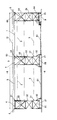
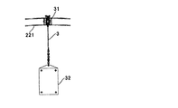
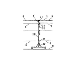
図1は湿潤養生を行う場合の養生装置1の一例を示す全体側面図である。図2は図1のII−II線に沿ったトンネルの横断面図で、この方向から見える養生台車2Bの正面を併せて描いた図であり、図3は同じくII−II線に沿ったトンネルの横断面図で、養生台車2の正面を省略した図である。養生装置1は、後述する三台の養生台車2A,2B,2Cを、長さ調整可能なジャッキ部材61,61で互いに連結したものである。そして、前側(トンネル開口から遠い側)の各養生台車2A,2Bの枠体22の円弧状部材221(図2)の後端部端縁全周に、複数のワイヤ体3の一端が周方向へ等間隔で固定されており、各ワイヤ体3はその一端から相互に平行でかつトンネル内周に略平行に後方へ延びて、その他端は、図4、図5に示すように、後側の各養生台車2B,2Cの枠体62の円弧状部材221の前端部端縁全周の対応位置に設けた懸架部材としてのシーブ31に懸架されて下方へ垂下している。垂下した各ワイヤ体3の下端にはウエイト32が装着されて、各ワイヤ体3に一定張力が付与されている。なお、最前位置の養生台車2Aは図略のモータによってレールRに沿って前後に自立移動可能である。もちろん、自立移動に代えて、前方に位置するセントルや他の養生装置に連結されて従動するものであっても良い。
(First Embodiment)
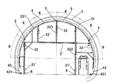
FIG. 1 is an overall side view showing an example of a curing device 1 in the case of performing wet curing. FIG. 2 is a cross-sectional view of the tunnel along the line II-II of FIG. 1, and is also a view showing the front of the
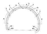
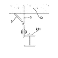
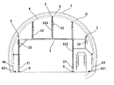
図2において、養生台車2は、車輪によってレールR上を移動可能な左右の基台21(図2)上に枠体22を架設したもので、枠体22は、トンネル形状に湾曲した円弧状部材221と、円弧状部材221を支持する柱部材222と、柱部材222と円弧状部材221とを連結する連結部材223とからなっており、円弧状部材221の外周がトンネルTの内周面に沿った円弧状をなし、トンネルTの内周面に打設されたコンクリートCrの内周面から一定距離だけ内方に位置してコンクリートCrの内周面との間に円弧断面の空間を形成している。そして、枠体22の外周部の円弧状部材221には周方向へ等間隔Eをおいて複数位置に、前方の養生台車2との間にワイヤ体3が張設されている。
In FIG. 2, the
このような構造によって、各ワイヤ体3には一定の張力が付与されている。加えて、前後の養生台車2と養生台車2の間隔が走行中に変動しあるいは当該間隔が調整変更された場合でも、これに応じてシーブ31が回転してワイヤ体3が繰り出されあるいは戻されて、ワイヤ体3の張力はウエイト32によって常に一定に保たれる。特に、レールRの敷設状態によっては養生台車2が移動時に前後左右に揺れて前後の養生台車2と養生台車2の間隔が変動することがあるが、この場合にもワイヤ体3の張力は常に一定に保たれる。
Due to such a structure, a constant tension is applied to each
そして、上記ワイヤ体3の外方には、トンネルTの内周面との間に、市販の防炎シートのようなシート体4が展開されて、図3に示すように、シート体4を複数のワイヤ体3で支持するようにこれらに被せられている。シート体4は区間D(図1)の長さとほぼ等しい長さが確保されており、トンネル周方向にもその円弧形状の長さに等しい幅の長さが確保されており、また、養生台車2のトンネル断面方向の左右下端においてはシート体4の下端42に適宜押さえ部材421が置かれている。これによって養生区間である区間Dの全域にわたって、打設されたコンクリートCrの内周面に沿った内方に円弧断面空間すなわち養生空間S(図3)が形成される。なお、シート体4には必要箇所にこれをワイヤ体3に係止固定するための係止具(図示略)が取り付けてある。
Then, a sheet body 4 such as a commercially available flameproof sheet is developed between the
なお、各養生台車2A〜2Cの枠体22の外周にはワイヤ体3は無くシート体4が直接張設される。また、最前位置の養生台車2Aの前端縁全周と最後位置の養生台車2Cの後端縁全周には,図6に示すように仕切板5が突設されていて、これらシート体4と仕切板5で養生空間Sが閉鎖されている。
There is no
養生台車2の外周にはワイヤ体3は無いので上記シート体4のみが張設されている(図1)。また、養生台車2の外周部の、トンネル入り口側端縁全周には、ウレタン等の弾性変形可能な樹脂製の仕切板5がトンネルTの内周面に向けて立設されており、養生空間Sのトンネル方向後端部を閉塞している。その詳細を図6に示す。
Since there is no
図6において、養生台車2の端縁全周に立設された仕切板5はコンクリートCrの内周面に向けて突出し、その先端部はコンクリートCrの内周面に当接して湾曲している。このような、養生台車2Aの前端と養生台車2Cの後端に設けられた仕切板5とシート体4、および押さえ部材421,421によって捲れないようにしたシート体4の両側方の下端42、42によって、コンクリートCrの内周面を覆う、区間D(図1)の長さにほぼ等しい、円弧断面の閉鎖された養生空間Sが形成される。
In FIG. 6, the
なお、養生台車2B,2Cの前方(図1の右方)の円弧状部材221,221に設けたブラケット311およびシーブ32は、養生台車2A,2Bの後方の円弧状部材221,221に設けてもよい。また、ワイヤ体3を養生台車2Aの前端に固定し、養生台車2Cの後端まで1本のワイヤ体3を張設してもよい。この場合、ワイヤ体3が枠体22の上部にも張り巡らせるので、養生台車2の上部のシート体4をワイヤ体3に支持させることができる。
The
ここで、最前位置の養生台車2Aには液体を貯留するタンク64が設けられ、さらに養生台車2A,2Bの枠体22の外周には周方向へ間隔をおいて複数の噴霧ノズル65が設けられてその先端はシート体4を貫通して養生空間S内に位置している。養生台車2Aに搭載された図略のポンプによって配管を経て各噴霧ノズル65に圧力液体が供給され、養生空間S内に細粒化された液体が噴霧される。また、養生台車2Aにはブロア(図示略)が搭載されており、ブロアから延びるダクトがシート体4を貫通して養生空間S内に開口している。これにより、養生空間S内に噴霧された液体が、ダクトから送出される気流によって満遍なく養生空間S内に行き渡る。ここで、上記液体は、水や温度調節された湯、あるいはコンクリートの養生液、スチーム等である。
Here, the curing
このような養生装置1を、外気遮断養生する養生装置に続いて設置することによって、外気遮断養生したコンクリートを、さらにコンクリート打設の長距離にわたって湿潤養生することができる。もちろん、湿潤養生することなく外気遮断養生をすることもできる。なお、本実施形態において、養生台車は必ずしも三台とする必要は無く、必要な複数台を設ければよい。 By installing such a curing device 1 following the curing device for blocking and curing the outside air, the concrete cured by blocking the outside air can be further wet-cured over a long distance of concrete placement. Of course, it is also possible to perform outdoor air blocking curing without moist curing. In this embodiment, the number of curing carriages does not necessarily have to be three, and a plurality of necessary curing carriages may be provided.
(第2実施形態)
図7には、本発明の第2実施形態における養生台車の側面図を示す。また、図8はこの場合の図2と同様のトンネルの横断面図である。第1実施形態における養生台車2は基台21のトンネル長さ方向の両端に枠体22を架設し、枠体22同士をブレースで連結しているが、本実施形態の養生台車2´では、車輪によってレールR上を移動可能な左右の基台21´(図8)上の、前後方向の略中央(図7)に枠体22´を架設している。枠体22´は、前記枠体22と同一構造である。すなわち、トンネル形状に湾曲した円弧状部材221´と、円弧状部材を前記基台21´を支える柱部材222´と、柱部材222´と円弧状部材221´とを連結する連結部材223´とからなっている。
(Second Embodiment)
FIG. 7 shows a side view of the curing carriage according to the second embodiment of the present invention. Further, FIG. 8 is a cross-sectional view of the same tunnel as in FIG. 2 in this case. In the curing
円弧状部材221´の外周がトンネルTの内周面に沿った円弧状をなし、トンネルTの内周面に打設されたコンクリートCrの内周面から一定距離だけ内方に位置してコンクリートCrの内周面との間に円弧断面の空間を形成している。そして、枠体22の外周部の円弧状部材221´には周方向へ等間隔Eをおいて複数位置に、前方の養生台車2´との間にワイヤ体3が張設されている。
The outer circumference of the arcuate member 221'forms an arc along the inner peripheral surface of the tunnel T, and the concrete is located inward by a certain distance from the inner peripheral surface of the concrete Cr placed on the inner peripheral surface of the tunnel T. A space having an arc cross section is formed between the inner peripheral surface of Cr and the inner peripheral surface of Cr. A
このような養生台車2´は、前記養生台車2Aと2B、2Bと2Cとの間に設置して、養生台車2Aと2B間のワイヤ体3やシート体4の弛みを支えることができる。また、養生台車2Aと2Cの間に設置して養生台車2Bを省略することもできる。この場合には、養生台車2´には、ワイヤ体3を固定せず、シーブ31も設けない。
Such a curing carriage 2'can be installed between the curing
(その他の実施形態)
上記各実施形態では、ワイヤ体への張力の付与をシーブとウエイトによって行っているが、例えばバネ部材等で行うようにしても良い。
なお、シーブに代えて例えば単なる棒体を、ワイヤ体を懸架する懸架部材として使用することができる。
また、養生台車と養生台車同士の間隔が変化しない場合は、ワイヤ体の両端を養生台車に固定する構造としても良い。
上記各実施形態で説明したものと異なって、養生台車2に、図9に示すように、円弧状枠部材221(図2参照)、221´(図8参照)を設けない構造としても良い。すなわち、養生台車2の上記枠体22、22´に、トンネル内周に沿った形状の枠部材221,221´を設けずに、トンネル内周方向に間隔を置いて複数の懸架部材を取り付けるようにしてもよい。たとえば、柱部材222,222´のトンネル内周面側先端や連結部材223,223´のトンネル内周面側の先端をトンネル内周に沿った形状に配して、それら先端に懸架部材を取り付けるようにしても良い。
(Other embodiments)
In each of the above embodiments, tension is applied to the wire body by a sheave and a weight, but for example, a spring member or the like may be used.
Instead of the sheave, for example, a simple rod body can be used as a suspension member for suspending the wire body.
Further, if the distance between the curing carriage and the curing carriage does not change, a structure may be used in which both ends of the wire body are fixed to the curing carriage.
As shown in FIG. 9, the curing
1…養生装置、2、2‘…養生台車、22、22’…枠体、3…ワイヤ体、31…シーブ、32…ウエイト、4…シート体、2A,2B.2C…養生台車、22,22‘…枠体、Cr…覆工コンクリート、S…養生空間、T…トンネル。 1 ... Curing device, 2, 2'... Curing trolley, 22, 22'... Frame body, 3 ... Wire body, 31 ... Sheave, 32 ... Weight, 4 ... Seat body, 2A, 2B. 2C ... Curing trolley, 22, 22'... Frame, Cr ... Lining concrete, S ... Curing space, T ... Tunnel.
Claims (5)
前記複数の養生台車の間に、これら養生台車の枠体の周方向で間隔をおいて複数張設されたワイヤ体と、
前記ワイヤ体に支持されて、覆工コンクリートの内周面に沿う内方に敷設されて、覆工コンクリートの内周面を覆う閉鎖された養生空間を形成するシート体と
を備える覆工コンクリートの養生装置。 A plurality of curing trolleys that are movable in the longitudinal direction of the tunnel, are positioned at predetermined intervals from each other, and have a frame having a shape along the inner circumference of the tunnel.
A plurality of wire bodies stretched between the plurality of curing carts at intervals in the circumferential direction of the frame of the curing carriage, and
A lining concrete provided with a sheet body supported by the wire body and laid inward along the inner peripheral surface of the lining concrete to form a closed curing space covering the inner peripheral surface of the lining concrete. Curing device.
Priority Applications (1)
| Application Number | Priority Date | Filing Date | Title |
|---|---|---|---|
| JP2017118176A JP6889875B2 (en) | 2017-06-16 | 2017-06-16 | Lining concrete curing equipment and curing trolley |
Applications Claiming Priority (1)
| Application Number | Priority Date | Filing Date | Title |
|---|---|---|---|
| JP2017118176A JP6889875B2 (en) | 2017-06-16 | 2017-06-16 | Lining concrete curing equipment and curing trolley |
Publications (2)
| Publication Number | Publication Date |
|---|---|
| JP2019002210A JP2019002210A (en) | 2019-01-10 |
| JP6889875B2 true JP6889875B2 (en) | 2021-06-18 |
Family
ID=65005738
Family Applications (1)
| Application Number | Title | Priority Date | Filing Date |
|---|---|---|---|
| JP2017118176A Active JP6889875B2 (en) | 2017-06-16 | 2017-06-16 | Lining concrete curing equipment and curing trolley |
Country Status (1)
| Country | Link |
|---|---|
| JP (1) | JP6889875B2 (en) |
Family Cites Families (7)
| Publication number | Priority date | Publication date | Assignee | Title |
|---|---|---|---|---|
| JPS63176577A (en) * | 1987-01-12 | 1988-07-20 | 株式会社竹中工務店 | Control of inflation mode in pneumatic film structure |
| JP2006089995A (en) * | 2004-09-22 | 2006-04-06 | Fukuda Corp | Tunnel lining concrete curing equipment |
| JP4552142B2 (en) * | 2005-03-17 | 2010-09-29 | 清水建設株式会社 | Lining concrete curing equipment |
| JP4750166B2 (en) * | 2008-09-30 | 2011-08-17 | 株式会社竹中土木 | Curing device and curing method for concrete continuum |
| KR101007691B1 (en) * | 2009-12-03 | 2011-01-13 | (주)이화기공 | Air balloon curing cart and curing method using the same |
| JP5073025B2 (en) * | 2010-08-19 | 2012-11-14 | 株式会社福田組 | Curing equipment |
| JP6259705B2 (en) * | 2014-04-15 | 2018-01-10 | 株式会社東宏 | Assembling structure and assembly method of tunnel curing sheet frame |
-
2017
- 2017-06-16 JP JP2017118176A patent/JP6889875B2/en active Active
Also Published As
| Publication number | Publication date |
|---|---|
| JP2019002210A (en) | 2019-01-10 |
Similar Documents
| Publication | Publication Date | Title |
|---|---|---|
| JP5818880B2 (en) | Linked vehicle for transporting rails | |
| JP6375390B2 (en) | Vehicle roof box mounting device | |
| US3337238A (en) | Splash guard structure | |
| JP2019142505A5 (en) | ||
| US10259414B2 (en) | Adjustable truck frame side guard assembly | |
| CA2422118A1 (en) | Support for a track-guided high-speed vehicle | |
| CN110356567A (en) | Guide rail covering members for the sliding seat guide rail between two passenger seats in the cabin of carrier | |
| EP2669134A1 (en) | Gangway side wall for a gangway between a first car of a multi-car vehicle and a second car of said vehicle comprising a side panel | |
| JP6889875B2 (en) | Lining concrete curing equipment and curing trolley | |
| JP4750166B2 (en) | Curing device and curing method for concrete continuum | |
| JP6860314B2 (en) | Curing device | |
| JP2010533616A5 (en) | ||
| JP5229638B2 (en) | Car wash equipment with processing equipment | |
| CN102333685A (en) | support base | |
| JP5118180B2 (en) | Curing equipment | |
| JP4444097B2 (en) | Concrete molding equipment | |
| SE535192C2 (en) | Method and device for converting vehicles | |
| JP4803907B2 (en) | Mobile assembly scaffold | |
| CN112298224B (en) | Operation vehicle for track beam | |
| JP2017025682A (en) | Concrete piping carriage and method for placing concrete | |
| JP6889443B2 (en) | Curing equipment and curing method for lining concrete | |
| JP7105439B2 (en) | Concrete placing device and concrete placing method | |
| KR101729749B1 (en) | A bracket for guide rails of elevator | |
| JP2005120746A (en) | Conveyor support device for tunnel construction equipment | |
| US1869205A (en) | Folding baby carriage |
Legal Events
| Date | Code | Title | Description |
|---|---|---|---|
| A621 | Written request for application examination |
Free format text: JAPANESE INTERMEDIATE CODE: A621 Effective date: 20200602 |
|
| A977 | Report on retrieval |
Free format text: JAPANESE INTERMEDIATE CODE: A971007 Effective date: 20210416 |
|
| TRDD | Decision of grant or rejection written | ||
| A01 | Written decision to grant a patent or to grant a registration (utility model) |
Free format text: JAPANESE INTERMEDIATE CODE: A01 Effective date: 20210511 |
|
| A61 | First payment of annual fees (during grant procedure) |
Free format text: JAPANESE INTERMEDIATE CODE: A61 Effective date: 20210512 |
|
| R150 | Certificate of patent or registration of utility model |
Ref document number: 6889875 Country of ref document: JP Free format text: JAPANESE INTERMEDIATE CODE: R150 |
|
| R250 | Receipt of annual fees |
Free format text: JAPANESE INTERMEDIATE CODE: R250 |