JP6889874B1 - Ropeway system and self-propelled ropeway equipment - Google Patents
Ropeway system and self-propelled ropeway equipment Download PDFInfo
- Publication number
- JP6889874B1 JP6889874B1 JP2021002544A JP2021002544A JP6889874B1 JP 6889874 B1 JP6889874 B1 JP 6889874B1 JP 2021002544 A JP2021002544 A JP 2021002544A JP 2021002544 A JP2021002544 A JP 2021002544A JP 6889874 B1 JP6889874 B1 JP 6889874B1
- Authority
- JP
- Japan
- Prior art keywords
- support
- rope
- ropeway
- end portion
- rail
- Prior art date
- Legal status (The legal status is an assumption and is not a legal conclusion. Google has not performed a legal analysis and makes no representation as to the accuracy of the status listed.)
- Active
Links
Images


Landscapes
- Platform Screen Doors And Railroad Systems (AREA)
Abstract
【課題】 市街地などの既存の複雑な領域であっても導入しやすい簡便且つ安価な自走式ロープウェイシステムを提供する。
【解決手段】 自走式ロープウェイシステムは、自走式ロープウェイ装置の進行方向において離隔されて設置された2つの支柱1の間の区間であり且つ接合部がない一連の支索11によって構成される区間である単位支索区間を複数連接するための中継器10を備え、中継器10は、前の単位支索区間を構成する支索11支索端部13に鋳止めされた状態で、支索端部13が支索固定具12に固定されるとともに、次の単位支索区間を構成する支索11が他の支索端部13に鋳止めされた状態で、他の支索端部13が支索固定具12に固定され、さらに、2つの支索端部13が設けられた領域を包含する領域にわたって、支索固定具12に支索端部走行用レール14が形成されている。
【選択図】 図2PROBLEM TO BE SOLVED: To provide a simple and inexpensive self-propelled ropeway system which is easy to introduce even in an existing complicated area such as an urban area.
SOLUTION: A self-propelled ropeway system is composed of a series of support ropes 11 which are a section between two columns 1 which are installed apart from each other in the traveling direction of the self-propelled ropeway device and have no joint. A repeater 10 for connecting a plurality of unit branch line sections, which is a section, is provided, and the repeater 10 is supported in a state of being cast to the support line 11 branch end portion 13 constituting the previous unit branch line section. In a state where the cable end portion 13 is fixed to the support rope fixing tool 12 and the support rope 11 constituting the next unit support line section is cast to the other support cable end portion 13, the other support rope end portion 13 is fixed to the support rope fixing tool 12, and the support cable end portion traveling rail 14 is formed on the support rope fixing tool 12 over an area including the area where the two support rope end portions 13 are provided. ..
[Selection diagram] Fig. 2
Description
本発明は、空中に架設されたワイヤロープやチェーンなどの支索に吊下された形態でロープウェイ装置が走行するロープウェイシステム、及びこのロープウェイシステムが備える自走式ロープウェイ装置に関する。 The present invention relates to a ropeway system in which a ropeway device travels in a form of being suspended from a support rope such as a wire rope or a chain erected in the air, and a self-propelled ropeway system included in the ropeway system.
現在のロープウェイシステムは、主に山間部における輸送手段として広く普及している。 The current ropeway system is widely used as a means of transportation mainly in mountainous areas.
例えば、特許文献1には、容器状のフレームの片側側面にデイスク式やドラム式の制動付きの溝付き車輪、側面を上下する溝付きの空回りする車輪、人体がぶら下がる取っ手を設定し、移動する場合制動付きの溝付き車輪と溝付きの空回りする車輪で支索の上面、下面を挟み、制動付きの溝付き車輪の制動を緩めるロープ式移動装置が開示されている。
For example, in
また、特許文献2には、ワイヤロープを挟むように対向して設けた複数組の1対のローラと、ワイヤロープに対して斜めに設けたガイドに沿って一方のローラをワイヤロープへ付勢させる付勢手段と、各ローラを回転させる駆動手段とで構成した、ワイヤロープ走行装置が開示されている。 Further, in Patent Document 2, a plurality of pairs of rollers provided so as to sandwich the wire rope and one roller are urged to the wire rope along a guide provided diagonally with respect to the wire rope. A wire rope traveling device including a urging means for urging and a driving means for rotating each roller is disclosed.
現在、人間の大量輸送手段として鉄道があるが、一部の国・地域において、ロープウェイシステムを利用することが試みられている。このようなロープウェイシステムは、建設費用が安価で済むことから、鉄道に代わるインフラストラクチャとして実現されれば、次世代のMaaS(Mobility as a Service)における輸送手段としてのポテンシャルが高いと考えられる。 Currently, there is a railroad as a means of mass transportation of human beings, but in some countries / regions, attempts are being made to use the ropeway system. Since such a ropeway system can be constructed at low cost, if it is realized as an infrastructure to replace the railway, it is considered to have high potential as a means of transportation in the next-generation MaaS (Mobility as a Service).
しかしながら、そのようなロープウェイシステムを、市街地をはじめとする様々な領域における輸送手段として実現するための具体的な技術的考察は、いまだ行われていないのが現状である。 However, at present, no concrete technical consideration has been made to realize such a ropeway system as a means of transportation in various areas including urban areas.
本発明は、このような実情に鑑みてなされたものであり、市街地などの既存の複雑な領域であっても導入しやすい簡便且つ安価な自走式ロープウェイシステム、並びに、ロープウェイシステムに用いられる中継器、分岐器、カーブ構造、及び自走式ロープウェイ装置を提供することを目的とする。 The present invention has been made in view of such circumstances, and is a simple and inexpensive self-propelled ropeway system that is easy to introduce even in an existing complicated area such as an urban area, and a relay used in a ropeway system. It is an object of the present invention to provide a vessel, a turnout, a curved structure, and a self-propelled ropeway device.
上述した目的を達成する本発明にかかるロープウェイシステムは、空中に架設された支索に吊下された形態でロープウェイ装置が走行するロープウェイシステムにおいて、ロープウェイ装置と、ロープウェイ装置の進行方向において離隔されて設置された2つの支柱間の区間であり且つ接合部がない一連の支索によって構成される区間である単位支索区間を複数連接するための中継器と、を備える。ロープウェイ装置は、客室を構成するチャンバの天面に設けられた駆動輪と、駆動輪に対応して設けられる受動輪であって、駆動輪の外周に設けられた溝と受動輪の外周に設けられた溝とによって支索を挟持して走行するように構成された受動輪と、を備える。中継器は、支柱に設けられ、支索を固定するための支索固定具を備え、前の単位支索区間を構成する支索の終端部分が所定の支索端部に鋳止めされた状態で、支索端部が支索固定具に固定されるとともに、次の単位支索区間を構成する支索の始端部分が他の支索端部に鋳止めされた状態で、他の支索端部が支索固定具に固定され、さらに、支索端部及び他の支索端部が設けられた領域を包含する領域にわたって、支索固定具に支索端部走行用レールが形成されており、支索端部走行用レールの上面の曲率半径は、支索の曲率半径と同一に形成されている。そして、駆動輪は、支索端部走行用レールの上面を介して、支索端部を越えて次の単位支索区間を構成する支索へと進行することを特徴としている。 The ropeway system according to the present invention that achieves the above-mentioned object is separated from the ropeway device in the traveling direction of the ropeway device in the ropeway system in which the ropeway device travels in a form suspended by a support rope erected in the air. It is provided with a repeater for connecting a plurality of unit cableway sections which are sections between two installed columns and which are sections composed of a series of cableways having no joints. The ropeway device is a drive wheel provided on the top surface of the chamber constituting the cabin and a passive wheel provided corresponding to the drive wheel, and is provided on a groove provided on the outer periphery of the drive wheel and on the outer periphery of the passive wheel. It is provided with a passive wheel configured to run with the support rope sandwiched between the grooves. The repeater is provided on a support column and is provided with a support rope fixing tool for fixing the support line, and a state in which the end portion of the support line constituting the previous unit support line section is cast to a predetermined support line end portion. Then, with the end of the support rail fixed to the support line fixture and the start end of the support line forming the next unit support section being cast to the other end of the support line, the other support line The end is fixed to the support, and the support rail is formed with a support rail for the end of the support over an area including the area where the end of the support and the other end of the support are provided. The radius of curvature of the upper surface of the rail for traveling at the end of the support rope is formed to be the same as the radius of curvature of the support line. The drive wheels are characterized in that they travel through the upper surface of the rail for traveling at the end of the branch to the branch that constitutes the next unit branch section beyond the end of the branch.
また、上述した目的を達成する本発明にかかるロープウェイシステムは、空中に架設された支索に吊下された形態でロープウェイ装置が走行するロープウェイシステムにおいて、ロープウェイ装置と、ロープウェイ装置を異なる進行方向に分岐するための分岐器と、を備える。ロープウェイ装置は、客室を構成するチャンバの天面に設けられた駆動輪と、駆動輪に対応して設けられる受動輪であって、駆動輪の外周に設けられた溝と受動輪の外周に設けられた溝とによって支索を挟持して走行するように構成された受動輪と、を備える。分岐器は、ロープウェイ装置の進行方向において離隔されて設置された2つの支柱間の区間であり且つ接合部がない一連の支索によって構成される区間を単位支索区間としたとき、支柱に設けられ、支索を固定するための支索固定具を備え、前の単位支索区間を構成する支索の終端部分が所定の支索端部に鋳止めされた状態で、支索端部が支索固定具に固定されるとともに、次の単位支索区間を構成する支索の始端部分が他の支索端部に鋳止めされた状態で、他の支索端部が支索固定具に固定され、さらに、支索端部及び他の支索端部が設けられた領域を包含する領域にわたって、支索固定具に支索端部走行用レールが形成されており、支索端部走行用レールの上面の曲率半径は、支索の曲率半径と同一に形成されている。そして、駆動輪は、支索端部走行用レールの上面を介して、支索端部を越えて次の単位支索区間を構成する支索へと進行することを特徴としている。 Further, the ropeway system according to the present invention that achieves the above-mentioned object is a ropeway system in which a ropeway device travels in a form of being suspended from a turnout erected in the air, and the ropeway device and the ropeway device are moved in different traveling directions. It is provided with a turnout for branching. The ropeway device is a drive wheel provided on the top surface of the chamber constituting the cabin and a passive wheel provided corresponding to the drive wheel, and is provided on a groove provided on the outer periphery of the drive wheel and on the outer periphery of the passive wheel. It is provided with a passive wheel configured to run with the support rope sandwiched between the grooves. The turnout is provided on the support column when the section between the two columns installed separated in the traveling direction of the ropeway device and composed of a series of support lines having no joint is used as the unit support section. With a turnout fixture for fixing the turnout, and the end of the turnout that constitutes the previous unit support section is cast to the predetermined turnout end, the turnout end is While being fixed to the turnout fixture, the other fulcrum ends are fixed to the other fulcrum ends while the start end of the fulcrum that constitutes the next unit branch section is cast to the other fulcrum end. A rail for traveling at the end of the support is formed on the support, and the end of the support is formed over an area including the area where the end of the support and the other end of the support are provided. The radius of curvature of the upper surface of the traveling rail is formed to be the same as the radius of curvature of the turnout. The drive wheels are characterized in that they travel through the upper surface of the rail for traveling at the end of the branch to the branch that constitutes the next unit branch section beyond the end of the branch.
さらに、上述した目的を達成する本発明にかかるロープウェイシステムは、空中に架設された支索に吊下された形態でロープウェイ装置が走行するロープウェイシステムにおいて、ロープウェイ装置と、ロープウェイ装置が支索に沿ってカーブすることを可能にするカーブ構造と、を備える。ロープウェイ装置は、客室を構成するチャンバの天面に設けられた駆動輪と、駆動輪に対応して設けられる受動輪であって、駆動輪の外周に設けられた溝と受動輪の外周に設けられた溝とによって支索を挟持して走行するように構成された受動輪と、を備える。カーブ構造は、ロープウェイ装置の進行方向において離隔されて設置された2つの支柱間の区間であり且つ接合部がない一連の支索によって構成される区間である単位支索区間を複数連接するための中継器と、カーブの始端及び終端に設けられた各中継器の間に延在し、所望の曲率に湾曲したカーブレールと、を備える。中継器は、支柱に設けられ、支索を固定するための支索固定具を備え、前の単位支索区間を構成する支索の終端部分が所定の支索端部に鋳止めされた状態で、支索端部が支索固定具に固定されるとともに、次の単位支索区間を構成する支索の始端部分が他の支索端部に鋳止めされた状態で、他の支索端部が支索固定具に固定され、さらに、支索端部及び他の支索端部が設けられた領域を包含する領域にわたって、支索固定具に支索端部走行用レールが形成されており、支索端部走行用レールの上面の曲率半径は、支索の曲率半径と同一に形成されている。そして、駆動輪は、支索端部走行用レールの上面を介して、支索端部を越えて次の単位支索区間を構成する支索へと進行することを特徴としている。 Further, the ropeway system according to the present invention that achieves the above-mentioned object is a ropeway system in which a ropeway device travels in a form of being suspended from a support line erected in the air. It has a curved structure that enables it to be curved. The ropeway device is a drive wheel provided on the top surface of the chamber constituting the cabin and a passive wheel provided corresponding to the drive wheel, and is provided on a groove provided on the outer periphery of the drive wheel and on the outer periphery of the passive wheel. It is provided with a passive wheel configured to run with the support rope sandwiched between the grooves. The curved structure is for connecting a plurality of unit branch sections, which are sections between two columns installed apart from each other in the traveling direction of the ropeway device and which are sections composed of a series of branches having no joints. It comprises a repeater and a curved rail extending between the repeaters provided at the beginning and end of the curve and curved to a desired curvature. The repeater is provided on a support column and is provided with a support rope fixing tool for fixing the support line, and a state in which the end portion of the support line constituting the previous unit support line section is cast to a predetermined support line end portion. Then, with the end of the support rail fixed to the support line fixture and the start end of the support line forming the next unit support section being cast to the other end of the support line, the other support line The end is fixed to the support, and the support rail is formed with a support rail for the end of the support over an area including the area where the end of the support and the other end of the support are provided. The radius of curvature of the upper surface of the rail for traveling at the end of the support rope is formed to be the same as the radius of curvature of the support line. The drive wheels are characterized in that they travel through the upper surface of the rail for traveling at the end of the branch to the branch that constitutes the next unit branch section beyond the end of the branch.
さらにまた、上述した目的を達成する本発明にかかる自走式ロープウェイ装置は、空中に架設された支索に吊下された形態で自走する自走式ロープウェイ装置において、客室を構成するチャンバの天面に設けられた駆動輪と、駆動輪に対応して設けられる受動輪であって、駆動輪の外周に設けられた溝と受動輪の外周に設けられた溝とによって支索を挟持して走行するように構成された受動輪と、駆動輪を回転駆動させる駆動モータに給電するバッテリと、を備え、駆動輪及び受動輪は、上述した中継器、分岐器、又はカーブ構造のうち少なくとも1つにおける支索端部を越えて次の単位支索区間を構成する支索へと進行することを特徴としている。 Furthermore, the self-propelled ropeway device according to the present invention that achieves the above-mentioned object is a self-propelled ropeway device that runs by itself in a form suspended from a turnout erected in the air. A support wheel is sandwiched between a drive wheel provided on the top surface and a passive wheel provided corresponding to the drive wheel, and a groove provided on the outer periphery of the drive wheel and a groove provided on the outer periphery of the passive wheel. The drive wheels and the passive wheels include at least one of the above-mentioned repeaters, turnouts, or curved structures, which comprises a passive wheel configured to travel and a battery that supplies power to a drive motor that rotationally drives the drive wheels. It is characterized in that it proceeds beyond one branch end to a branch that constitutes the next unit branch section.
このような本発明にかかるロープウェイシステム及び自走式ロープウェイ装置は、前の単位支索区間を構成する支索が所定の支索端部に鋳止めされた状態で、支索端部が支索固定具に固定されるとともに、支索固定具に支索端部走行用レールが形成され、支索端部走行用レールの終端には、次の単位支索区間を構成する支索が連絡しており、支索端部走行用レールの上面の曲率半径が支索の曲率半径と同一に形成されていることから、ロープウェイ装置の駆動輪及び受動輪によって支索端部走行用レールの上面を介して支索端部を越えて次の単位支索区間を構成する支索へと進行する。 In such a ropeway system and a self-propelled ropeway device according to the present invention, the branch end portion is a branch rope in a state where the branch rope constituting the previous unit branch rope section is cast to a predetermined branch end portion. Along with being fixed to the fixture, a support rail for running at the end of the support rope is formed on the support, and the end of the rail for running at the end of the support is connected to the support rope that constitutes the next unit support section. and which, since the radius of curvature of the upper surface of支索end traveling rails are formed on the same radius of curvature of支索, the upper surface of支索end traveling rail by a drive wheel and driven wheel ropeway device Through the end of the cableway, the cableway proceeds to the cableway that constitutes the next unit cableway section.
本発明においては、簡便且つ安価な構成のもとに、安定したロープウェイ装置の走行を実現することができ、市街地などの既存の複雑な領域であっても容易に導入することができる。 In the present invention, stable running of the ropeway device can be realized based on a simple and inexpensive configuration, and it can be easily introduced even in an existing complicated area such as an urban area.
以下、本発明を適用した具体的な実施の形態について図面を参照しながら詳細に説明する。 Hereinafter, specific embodiments to which the present invention is applied will be described in detail with reference to the drawings.
この実施の形態は、空中に架設されたワイヤロープやチェーンなどの支索に吊下された形態で自走式ロープウェイ装置が自走する自走式ロープウェイシステムである。 This embodiment is a self-propelled ropeway system in which a self-propelled ropeway device is self-propelled in a form of being suspended from a support rope such as a wire rope or a chain erected in the air.
この自走式ロープウェイシステムは、詳細は後述するが、空中に架設されたワイヤロープなどの支索を自走式ロープウェイ装置の駆動輪と受動輪とによって挟持して互いに押し付ける構造を基本としている。以下では、自走式ロープウェイ装置が進行する方向を「進行方向」と称し、この進行方向に直交する鉛直方向を「上下方向」と称し、進行方向に直交する面内方向を「左右方向」と称するものとする。 Although details will be described later, this self-propelled ropeway system is based on a structure in which a support rope such as a wire rope erected in the air is sandwiched between the drive wheels and passive wheels of the self-propelled ropeway device and pressed against each other. In the following, the direction in which the self-propelled ropeway device travels is referred to as the "traveling direction", the vertical direction orthogonal to the traveling direction is referred to as the "vertical direction", and the in-plane direction orthogonal to the traveling direction is referred to as the "left-right direction". It shall be referred to.
このような自走式ロープウェイシステムを市街地などの既存の複雑な領域に導入するためには、単位支索区間を複数連接するための中継器と、異なる進行方向に分岐するための分岐器と、自走式ロープウェイ装置が支索に沿って滑らかにカーブすることを可能にするカーブ構造と、を如何に構成するかが重要となる。以下では、この3つの要素について詳細に説明する。 In order to introduce such a self-propelled ropeway system into an existing complicated area such as an urban area, a repeater for connecting a plurality of unit branch sections and a turnout for branching in different traveling directions are used. It is important how to construct a curved structure that enables the self-propelled ropeway device to smoothly curve along the turnout. In the following, these three elements will be described in detail.
まず、中継器について説明する。 First, the repeater will be described.
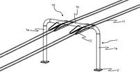
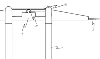
図1に、中継器部分の概略図を示す。中継器10は、地面などの基礎面に敷設された基礎2から立設される支柱1に構成される。支柱1は、2つの基礎2からそれぞれ立設される2本の脚部1aと、これら脚部1aの間をつなぐ水平部1bとを有するコ字状に形成されている。また、支柱1は、必要に応じて、図7に示すように、傾きを防止するために、脚部1aから延出された支柱固定用ロープ3を基礎面に固定することによって補強されていてもよい。自走式ロープウェイシステムにおいては、自走式ロープウェイ装置の進行方向において離隔されて設置された前後2つの支柱1の間の区間を単位支索区間、すなわち、接合部がない一連の支索11によって構成される区間とし、この単位支索区間を複数連接することによって任意距離のシステムを実現する。
FIG. 1 shows a schematic view of the repeater portion. The
前後2つの支柱1の間には、支索11が架設されている。支索11は、支柱1の水平部1bの左右方向両側に2本ずつ、計4本設けられる。このうち、片側2本の支索11は、所定の進行方向用であり、他側2本の支索11は、反対の進行方向用である。支索11は、支柱1、特に脚部1aから離隔した位置に架設されている。ここでは図示しないが、自走式ロープウェイ装置は、その駆動輪と受動輪とによって支索11を上下方向に挟持して互いに押し付けながら走行する。
A
さらに、支柱1の水平部1bには、その左右方向両側に、支索11を固定するための支索固定具12が設けられる。この支索固定具12は、支索11毎に設けられ、図1の場合には、4本の支索11に対応して4つの支索固定具12が設けられる。特に、支索固定具12は、支柱1の脚部1aから所定距離離隔した位置に設けられる。すなわち、中継器10は、支柱1の脚部1aから所定距離離隔した位置に設けられる。
Further, the
中継器10においては、前の単位支索区間から次の単位支索区間への支索11の連接形態に工夫を凝らさないと、滑らかな走行を実現することが困難となる。
In the
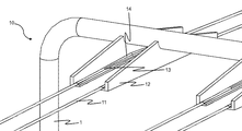
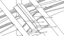
そこで、中継器10は、図2に示すように、筒状の支索端部13に形成された筒孔に、前の単位支索区間を構成する支索11の終端部分を挿入して所定の金属を流し込むことによって支索11を支索端部13に鋳止めした状態で、支索端部13を支索固定具12にネジなどによって機械的に固定するとともに、次の単位支索区間を構成する支索11の始端部分を他の支索端部13に鋳止めした状態で、他の支索端部13を支索固定具12に固定し、さらに、2つの支索端部13が設けられた領域を包含する領域にわたって、支索固定具12に支索端部走行用レール14を形成している。
Therefore, as shown in FIG. 2, the
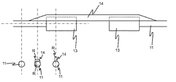
ここで、支索端部走行用レール14は、図3に示すように、支索端部13に鋳止めされた支索11よりも若干上方に形成されている。また、支索端部13は、支索11を鋳止めする構成のため、支索11よりも曲率半径が大きくなることから、そのままでは自走式ロープウェイ装置の1対の駆動輪及び受動輪によって通過することができない。そこで、支索端部走行用レール14の上面の曲率半径を支索11の曲率半径Rと同一に形成している。これにより、自走式ロープウェイ装置は、支索端部13の設置領域付近であっても、1対の駆動輪及び受動輪によって滑らかに走行することができる。なお、支索固定具12及び支索端部走行用レール14には、前後の支索11による張力が伝達されていることはいうまでもない。
Here, as shown in FIG. 3, the support rail end
このような構成により、自走式ロープウェイ装置は、その駆動輪及び受動輪によって支索端部13を越えて支索端部走行用レール14に沿って走行し、次の単位支索区間を構成する支索11へとシームレスに進行することができる。したがって、自走式ロープウェイシステムにおいては、このような簡便且つ安価な構成のもとに、走行中のがたつきを低減した滑らかな走行を実現することができる。
With such a configuration, the self-propelled ropeway device travels along the support rail
つぎに、分岐器について説明する。 Next, the turnout will be described.
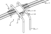
分岐器は、自走式ロープウェイ装置を異なる進行方向に分岐するためのポインタである。図4に、分岐器部分の概略図を示す。分岐器20は、中継器10と同様に、支柱1に上述した支索固定具12を設けることによって形成される。なお、支索固定具12の周辺における支索11の固定については、中継器10と同様に、図4では図示しない筒状の支索端部13に形成された筒孔に、前の単位支索区間を構成する支索11の終端部分を挿入して所定の金属を流し込むことによって支索11を支索端部13に鋳止めした状態で、支索端部13を支索固定具12にネジなどによって機械的に固定するとともに、次の単位支索区間を構成する支索11の始端部分を他の支索端部13に鋳止めした状態で、他の支索端部13を支索固定具12に固定し、さらに、2つの支索端部13が設けられた領域を包含する領域にわたって、支索固定具12に支索端部走行用レール14を形成したものである。
A turnout is a pointer for branching a self-propelled ropeway device in different directions of travel. FIG. 4 shows a schematic view of the turnout portion. The
分岐器20は、分岐器20を駆動するための分岐器駆動用モータ21と、この分岐器駆動用モータ21から延出する分岐器駆動力伝達軸22と、後述するリニアガイドを支持固定するための支柱側リニアガイド固定具23とを備える。
The
分岐器駆動用モータ21は、分岐器20、より具体的には後述するリニアガイドを駆動するための駆動力を発生する駆動源である。分岐器駆動用モータ21の回転は、分岐器駆動力伝達軸22を介してリニアガイドに伝達される。
The
支柱側リニアガイド固定具23は、進行方向前後に位置する2本1組の支柱1にわたって当該支柱1の水平部1bに設けられており、図4では図示しないリニアガイドを支柱1の側から支持固定する。
The support column side
図5及び図6に、支柱側リニアガイド固定具23を取り外した様子を示し、図7に、分岐器20の横断面図を示す。分岐器20は、分岐器駆動力伝達軸22を介して伝達される駆動力に応じて平行移動するリニアガイド24と、リニアガイド24を支持固定するための分岐器側リニアガイド固定具25と、分岐器20内における進行方向が直進のレールである分岐器内直進レール26と、分岐器20内における進行方向が直進から分岐したレールである分岐器内分岐レール27と、分岐器20内における各レールを支持する分岐器内レール支持面28とを備える。
5 and 6 show a state in which the support column side
リニアガイド24は、図5及び図6に示すように、分岐器側リニアガイド固定具25によって下方から支持固定されるとともに、図7に示すように、支柱側リニアガイド固定具23によって支柱1の側から支持固定されており、分岐器駆動力伝達軸22を介して伝達される分岐器駆動用モータ21の駆動力に応じて、左右方向(図7では、紙面に対して鉛直方向)へと平行移動する。分岐器20内では、分岐器内直進レール26及び分岐器内分岐レール27の2本のレールが延在しており、リニアガイド24の平行移動に応じて、分岐器内直進レール26及び/又は分岐器内分岐レール27が移動することにより、いずれか一方のレールのみが次の進行方向のレールとして切り替え選択されることになる。
As shown in FIGS. 5 and 6, the
このような構成により、自走式ロープウェイ装置は、リニアガイド24の平行移動に応じて切り替え選択された分岐器内直進レール26又は分岐器内分岐レール27のいずれか一方にのみ沿って走行することができる。なお、分岐器20によるレールの切り替え選択制御、すなわち分岐器駆動用モータ21の制御は、図示しないコントローラによって行われる。自走式ロープウェイ装置は、分岐器20上で一旦停止し、吊下されているレールが平行移動することによって走行すべき方向に切り替えられる。自走式ロープウェイシステムにおいては、このような簡便且つ安価な構成のもとに、進行方向の分岐を容易に実現することができる。
With such a configuration, the self-propelled ropeway device travels only along either the straight-
つぎに、カーブ構造について説明する。 Next, the curve structure will be described.
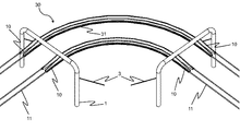
図8に、カーブ構造部分の概略図を示す。カーブ構造30は、1つの単位支索区間を構成するため、カーブの始端及び終端には上述した中継器10を用いる。そして、始端及び終端の各中継器10の間には、所望の曲率に湾曲したカーブレール31が延在している。
FIG. 8 shows a schematic view of the curve structure portion. Since the
カーブレール31は、図9に示すように、カーブレール固定具32によって支持固定されている。なお、支索固定具12における支索11の固定については、中継器10及び分岐器20と同様に、筒状の支索端部13に形成された筒孔に、カーブレール31に沿った支索11の終端部分を挿入して所定の金属を流し込むことによって支索11を支索端部13に鋳止めした状態で、支索端部13を支索固定具12にネジなどによって機械的に固定するとともに、次の単位支索区間を構成する支索11の始端部分を他の支索端部13に鋳止めした状態で、他の支索端部13を支索固定具12に固定し、さらに、2つの支索端部13が設けられた領域を包含する領域にわたって、支索固定具12に支索端部走行用レール14を形成したものである。
As shown in FIG. 9, the
このような構成により、自走式ロープウェイ装置は、カーブレール31に沿って滑らかに走行した後、支索端部13を越えて支索端部走行用レール14に沿って走行し、次の単位支索区間を構成する支索11へとシームレスに進行することができる。したがって、自走式ロープウェイシステムにおいては、このような簡便且つ安価な構成のもとに、走行中のがたつきを低減した滑らかな走行が可能なカーブ構造30を実現することができる。
With such a configuration, the self-propelled ropeway device smoothly travels along the
最後に、このような自走式ロープウェイシステムにおける走行車両としての自走式ロープウェイ装置について説明する。 Finally, a self-propelled ropeway device as a traveling vehicle in such a self-propelled ropeway system will be described.
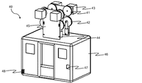
図10に、自走式ロープウェイ装置の概略図を示す。自走式ロープウェイ装置40は、客室を構成するチャンバ46の天面において上下方向に並設された駆動輪41の外周に設けられた溝と受動輪42の外周に設けられた溝とによって支索11を上下方向に挟持して走行するように構成される。ここでは、駆動輪41及び受動輪42の対は、左右の支索11に対応して左右方向に2対設けられ、且つ、進行方向にも2対設けられている。
FIG. 10 shows a schematic view of the self-propelled ropeway device. The self-propelled
駆動輪41には、自走式ロープウェイ装置40に対して着脱可能とされる交換式バッテリソケット47からの給電によって駆動する駆動モータ43が連結されており、駆動輪41は、この駆動モータ43の駆動に応じて回転駆動する。なお、駆動モータ43は、例えば、その優れた動作の滑らかさを享受するために、近年電気自動車などに用いられるインホイールモータを用いることができるが、コスト重視の場合には、通常の電気モータを用いてもよい。
A
一方、受動輪42には、駆動源は設けられておらず、代わりに、受動圧調整リニアアクチュエータ44が連結されている。受動輪42は、この受動圧調整リニアアクチュエータ44の作用によって駆動輪41に押し付けられ、駆動輪41の回転駆動にともなって連れ回るように構成される。すなわち、駆動輪41と受動輪42との間の距離は可変とされ、受動圧調整リニアアクチュエータ44の作用によってその距離を調整することができるようになっている。なお、受動圧調整リニアアクチュエータ44による押圧力は、駆動輪41及び受動輪42が支索11から外れることがない程度であり且つ支索11を圧潰しない程度に設定される。
On the other hand, the
これらの駆動輪41、受動輪42、駆動モータ43及び受動圧調整リニアアクチュエータ44は、チャンバ46の天面に設けられた駆動部固定具45によって支持固定されている。自走式ロープウェイ装置40は、このような駆動輪41と受動輪42とによって支索11を上下方向に挟持して互いに押し付けながら走行するように構成される。なお、駆動輪41及び受動輪42の対は、図10に示すように、上側が駆動輪41且つ下側が受動輪42といったように全て同じ方向に対向していてもよいが、支索11の圧潰を最低限にするために、進行方向に設けられた2対のうち、一方の対については、上側が駆動輪41且つ下側が受動輪42とし、他方の対については、下側が駆動輪41且つ上側が受動輪42とするといったように交互配置としてもよい。
These drive
このような自走式ロープウェイ装置40は、図示しない駅舎に停車しているときに、駅舎に設けられた給電設備から給電される給電用アダプタ48を備え、この給電用アダプタ48によって交換式バッテリソケット47への充電を行うように構成される。そして、自走式ロープウェイ装置40は、交換式バッテリソケット47からの電力によって駆動モータ43を駆動することによって自走する。したがって、自走式ロープウェイシステムにおいては、支索11にはいかなる給電設備も不要であり、大幅な安価化を奏することができる。
Such a self-propelled
なお、駅舎については特に図示しないが、人間が昇降可能な程度のスペースがあればよく、例えば、既存の建物の屋根やバルコニーそのものの他、建物の壁に設置した簡易的な設備などで十分に足りる。この点でも、自走式ロープウェイシステムは、極めて簡便且つ安価に構築することができ、市街地などの既存の複雑な領域にも容易に導入することができる。 Although the station building is not shown in particular, it is sufficient if there is enough space for humans to move up and down. For example, in addition to the roof and balcony of the existing building, simple equipment installed on the wall of the building is sufficient. Sufficient. In this respect as well, the self-propelled ropeway system can be constructed extremely easily and inexpensively, and can be easily introduced into existing complicated areas such as urban areas.
なお、本発明は、上述した実施の形態に限定されるものではない。 The present invention is not limited to the above-described embodiment.
例えば、上述した実施の形態では、自走式ロープウェイ装置40が駆動輪41と受動輪42とによって支索11を上下方向に挟持して互いに押し付けながら走行するものとして説明したが、本発明は、駆動輪41及び受動輪42を左右方向に並設し、支索11を左右方向に挟持して互いに押し付けながら走行するものであってもよい。また、駆動輪41及び受動輪42の対は、中掴み構造/外掴み構造のいずれであってもよい。
For example, in the above-described embodiment, the self-propelled
また、上述した実施の形態では、支索11が図1に示したように進行方向あたり片側2本ずつ設けるものとして説明したが、本発明においては、支索11が、支柱1の水平部1bの左右方向両側に少なくとも1本ずつ設けられるのであれば、その本数に限定されるものではない。ただし、支索11は、安全上及び走行安定性の理由から、片側2本ずつ設けるのが好ましい。
Further, in the above-described embodiment, it has been described that the
さらに、上述した実施の形態では、駆動輪41及び受動輪42の対が、図10に示すように、左右の支索11に対応して左右方向に2対設けられ、且つ、進行方向にも2対設けられるものとして説明したが、本発明においては、駆動輪41及び受動輪42の対として、例えば、支索11の本数が1本である場合には、進行方向に2対設けるか、又は、自走式ロープウェイ装置40の平面視中央付近に1対のみ設けるといったように、支索11の本数や必要な安定性を考慮して決めればよい。
Further, in the above-described embodiment, as shown in FIG. 10, two pairs of
さらにまた、上述した実施の形態では、支索固定具12に固定された支索端部13に、前の単位支索区間を構成する支索11が鋳止めされることにより、支索11を支索固定具12に固定しているが、支索固定具12として、例えば、鉄製基材上にゴムライナーを載置し、ゴムライナーに支索11を支持するための支持溝を刻設して構成されたものとし、支索11を、支索固定具12に完全に固定するのではなく、支索固定具12のゴムライナーに刻設された支持溝に載置するのみでもよい。
Furthermore, in the above-described embodiment, the
さらにまた、上述した実施の形態では、自走式であるものとして説明したが、中継器、分岐器、及びカーブ構造自体は、非自走式のロープウェイ装置が走行する場合にも適用可能であり、本発明は、そのような非自走式のロープウェイ装置が走行するロープウェイシステムも包含する。 Furthermore, in the above-described embodiment, it has been described as being self-propelled, but the repeater, the turnout, and the curve structure itself can be applied to the case where the non-self-propelled ropeway device travels. The present invention also includes a ropeway system on which such a non-self-propelled ropeway device runs.
また、上述した実施の形態では、駆動輪41と受動輪42との間の距離を調整する手段として受動圧調整リニアアクチュエータ44を用いるものとして説明したが、本発明は、バネなどの緩衝手段によって簡易的に構成してもよく、駆動輪41と受動輪42との間の距離を調整する距離調整手段であれば、いかなる形態のものであっても適用することができる。
Further, in the above-described embodiment, the passive pressure adjusting
さらに、上述した実施の形態では、駅舎に設けられた給電設備から給電用アダプタ48を介して給電されるものとして説明したが、本発明は、鉄道のように外部トロリー線による給電を行うようにしてもよい。
Further, in the above-described embodiment, power is supplied from the power supply equipment provided in the station building via the
このように、本発明は、その趣旨を逸脱しない範囲で適宜変更が可能であることはいうまでもない。 As described above, it goes without saying that the present invention can be appropriately modified without departing from the spirit of the present invention.
1 支柱
1a 脚部
1b 水平部
2 基礎
3 支柱固定用ロープ
10 中継器
11 支索
12 支索固定具
13 支索端部
14 支索端部走行用レール
20 分岐器
21 分岐器駆動モータ
22 分岐器動力伝達軸
23 支柱側リニアガイド固定具
24 リニアガイド
25 分岐器側リニアガイド固定具
26 分岐器内直進レール
27 分岐器内分岐レール
30 カーブ構造
31 カーブレール
32 カーブレール固定具
40 自走式ロープウェイ装置
41 駆動輪
42 受動輪
43 駆動モータ
44 受動圧調整リニアアクチュエータ
45 駆動部固定具
46 チャンバ
47 交換式バッテリソケット
48 給電用アダプタ
R 曲率半径
1
Claims (6)
前記ロープウェイ装置と、
前記ロープウェイ装置の進行方向において離隔されて設置された2つの支柱間の区間であり且つ接合部がない一連の前記支索によって構成される区間である単位支索区間を複数連接するための中継器と、を備え、
前記ロープウェイ装置は、
客室を構成するチャンバの天面に設けられた駆動輪と、
前記駆動輪に対応して設けられる受動輪であって、前記駆動輪の外周に設けられた溝と前記受動輪の外周に設けられた溝とによって前記支索を挟持して走行するように構成された受動輪と、を備え、
前記中継器は、
前記支柱に設けられ、前記支索を固定するための支索固定具を備え、
前の単位支索区間を構成する前記支索の終端部分が所定の支索端部に鋳止めされた状態で、前記支索端部が前記支索固定具に固定されるとともに、次の単位支索区間を構成する前記支索の始端部分が他の支索端部に鋳止めされた状態で、前記他の支索端部が前記支索固定具に固定され、さらに、前記支索端部及び前記他の支索端部が設けられた領域を包含する領域にわたって、前記支索固定具に支索端部走行用レールが形成されており、
前記支索端部走行用レールの上面の曲率半径は、前記支索の曲率半径と同一に形成されており、
前記駆動輪は、前記支索端部走行用レールの上面を介して、前記支索端部を越えて次の単位支索区間を構成する前記支索へと進行すること
を特徴とするロープウェイシステム。 In a ropeway system in which a ropeway device runs in a form suspended from a support rope erected in the air.
With the ropeway device
A repeater for connecting a plurality of unit branch sections, which are sections between two columns installed apart from each other in the traveling direction of the ropeway device and which are sections composed of a series of the branch ropes having no joints. And with
The ropeway device
The drive wheels provided on the top of the chamber that make up the guest room,
It is a passive wheel provided corresponding to the drive wheel, and is configured to run while sandwiching the support rope by a groove provided on the outer circumference of the drive wheel and a groove provided on the outer circumference of the passive wheel. With a passive wheel,
The repeater
Provided on the support column and provided with a support rope fixing tool for fixing the support rope.
In a state where the end portion of the support rope constituting the previous unit support line section is cast to a predetermined support line end portion, the support line end portion is fixed to the support line fixture, and the next unit In a state where the starting end portion of the supporting rope constituting the supporting rope section is cast to the other supporting rope end portion, the other supporting rope end portion is fixed to the supporting rope fixing tool, and further, the supporting rope end portion is fixed. A rail for traveling at the end of the fulcrum is formed in the fulcrum fixture over an area including the portion and the area where the other end of the fulcrum is provided.
The radius of curvature of the upper surface of the rail for traveling at the end of the support rope is formed to be the same as the radius of curvature of the support rope.
The ropeway system is characterized in that the drive wheels travel through the upper surface of the rail for traveling at the end of the branch to the branch that constitutes the next unit branch section beyond the end of the support. ..
前記ロープウェイ装置と、
前記ロープウェイ装置を異なる進行方向に分岐するための分岐器と、を備え、
前記ロープウェイ装置は、
客室を構成するチャンバの天面に設けられた駆動輪と、
前記駆動輪に対応して設けられる受動輪であって、前記駆動輪の外周に設けられた溝と前記受動輪の外周に設けられた溝とによって前記支索を挟持して走行するように構成された受動輪と、を備え、
前記分岐器は、
前記ロープウェイ装置の進行方向において離隔されて設置された2つの支柱間の区間であり且つ接合部がない一連の前記支索によって構成される区間を単位支索区間としたとき、前記支柱に設けられ、前記支索を固定するための支索固定具を備え、
前の単位支索区間を構成する前記支索の終端部分が所定の支索端部に鋳止めされた状態で、前記支索端部が前記支索固定具に固定されるとともに、次の単位支索区間を構成する前記支索の始端部分が他の支索端部に鋳止めされた状態で、前記他の支索端部が前記支索固定具に固定され、さらに、前記支索端部及び前記他の支索端部が設けられた領域を包含する領域にわたって、前記支索固定具に支索端部走行用レールが形成されており、
前記支索端部走行用レールの上面の曲率半径は、前記支索の曲率半径と同一に形成されており、
前記駆動輪は、前記支索端部走行用レールの上面を介して、前記支索端部を越えて次の単位支索区間を構成する前記支索へと進行すること
を特徴とするロープウェイシステム。 In a ropeway system in which a ropeway device runs in a form suspended from a support rope erected in the air.
With the ropeway device
The ropeway device is provided with a turnout for branching in different traveling directions.
The ropeway device
The drive wheels provided on the top of the chamber that make up the guest room,
It is a passive wheel provided corresponding to the drive wheel, and is configured to run while sandwiching the support rope by a groove provided on the outer circumference of the drive wheel and a groove provided on the outer circumference of the passive wheel. With a passive wheel,
The turnout
When a section composed of a series of the support ropes that are separated from each other in the traveling direction of the ropeway device and have no joints is defined as a unit support line section, the support columns are provided. , Equipped with a cableway fixture for fixing the cableway,
In a state where the end portion of the support rope constituting the previous unit support line section is cast to a predetermined support line end portion, the support line end portion is fixed to the support line fixture, and the next unit In a state where the starting end portion of the supporting rope constituting the supporting rope section is cast to the other supporting rope end portion, the other supporting rope end portion is fixed to the supporting rope fixing tool, and further, the supporting rope end portion is fixed. A rail for traveling at the end of the fulcrum is formed in the fulcrum fixture over an area including the portion and the area where the other end of the fulcrum is provided.
The radius of curvature of the upper surface of the rail for traveling at the end of the support rope is formed to be the same as the radius of curvature of the support rope.
The ropeway system is characterized in that the drive wheels travel through the upper surface of the rail for traveling at the end of the branch to the branch that constitutes the next unit branch section beyond the end of the support. ..
分岐器駆動用モータの駆動力に応じて平行移動するリニアガイドと、
当該分岐器内における進行方向が直進のレールである分岐器内直進レールと、
当該分岐器内における進行方向が直進から分岐したレールである分岐器内分岐レールと、を備え、
前記リニアガイドの平行移動に応じて、前記分岐器内直進レール又は前記分岐器内分岐レールのうちいずれか一方のレールのみが次の進行方向のレールとして切り替え選択されること
を特徴とする請求項2に記載のロープウェイシステム。 The turnout
A linear guide that moves in parallel according to the driving force of the turnout drive motor,
A straight rail in a turnout, which is a rail that goes straight in the direction of travel in the turnout,
A branch rail in a turnout, which is a rail in which the traveling direction in the turnout is branched from a straight line, is provided.
The claim is characterized in that, in response to the translation of the linear guide, only one of the straight rail in the turnout or the branch rail in the turnout is switched and selected as the rail in the next traveling direction. The ropeway system according to 2.
前記ロープウェイ装置と、
前記ロープウェイ装置が前記支索に沿ってカーブすることを可能にするカーブ構造と、を備え、
前記ロープウェイ装置は、
客室を構成するチャンバの天面に設けられた駆動輪と、
前記駆動輪に対応して設けられる受動輪であって、前記駆動輪の外周に設けられた溝と前記受動輪の外周に設けられた溝とによって前記支索を挟持して走行するように構成された受動輪と、を備え、
前記カーブ構造は、
前記ロープウェイ装置の進行方向において離隔されて設置された2つの支柱間の区間であり且つ接合部がない一連の前記支索によって構成される区間である単位支索区間を複数連接するための中継器と、
カーブの始端及び終端に設けられた各中継器の間に延在し、所望の曲率に湾曲したカーブレールと、を備え、
前記中継器は、
前記支柱に設けられ、前記支索を固定するための支索固定具を備え、
前の単位支索区間を構成する前記支索の終端部分が所定の支索端部に鋳止めされた状態で、前記支索端部が前記支索固定具に固定されるとともに、次の単位支索区間を構成する前記支索の始端部分が他の支索端部に鋳止めされた状態で、前記他の支索端部が前記支索固定具に固定され、さらに、前記支索端部及び前記他の支索端部が設けられた領域を包含する領域にわたって、前記支索固定具に支索端部走行用レールが形成されており、
前記支索端部走行用レールの上面の曲率半径は、前記支索の曲率半径と同一に形成されており、
前記駆動輪は、前記支索端部走行用レールの上面を介して、前記支索端部を越えて次の単位支索区間を構成する前記支索へと進行すること
を特徴とするロープウェイシステム。 In a ropeway system in which a ropeway device runs in a form suspended from a support rope erected in the air.
With the ropeway device
It comprises a curved structure that allows the ropeway device to curve along the tributary.
The ropeway device
The drive wheels provided on the top of the chamber that make up the guest room,
It is a passive wheel provided corresponding to the drive wheel, and is configured to run while sandwiching the support rope by a groove provided on the outer circumference of the drive wheel and a groove provided on the outer circumference of the passive wheel. With a passive wheel,
The curve structure is
A repeater for connecting a plurality of unit branch sections, which are sections between two columns installed apart from each other in the traveling direction of the ropeway device and which are sections composed of a series of the branch ropes having no joints. When,
A curved rail that extends between each repeater provided at the beginning and end of the curve and is curved to the desired curvature.
The repeater
Provided on the support column and provided with a support rope fixing tool for fixing the support rope.
In a state where the end portion of the support rope constituting the previous unit support line section is cast to a predetermined support line end portion, the support line end portion is fixed to the support line fixture, and the next unit In a state where the starting end portion of the supporting rope constituting the supporting rope section is cast to the other supporting rope end portion, the other supporting rope end portion is fixed to the supporting rope fixing tool, and further, the supporting rope end portion is fixed. A rail for traveling at the end of the fulcrum is formed in the fulcrum fixture over an area including the portion and the area where the other end of the fulcrum is provided.
The radius of curvature of the upper surface of the rail for traveling at the end of the support rope is formed to be the same as the radius of curvature of the support rope.
The ropeway system is characterized in that the drive wheels travel through the upper surface of the rail for traveling at the end of the branch to the branch that constitutes the next unit branch section beyond the end of the support. ..
客室を構成するチャンバの天面に設けられた駆動輪と、
前記駆動輪に対応して設けられる受動輪であって、前記駆動輪の外周に設けられた溝と前記受動輪の外周に設けられた溝とによって前記支索を挟持して走行するように構成された受動輪と、
前記駆動輪を回転駆動させる駆動モータに給電するバッテリと、を備え、
前記駆動輪及び前記受動輪は、請求項1に記載の中継器、請求項2若しくは請求項3に記載の分岐器、又は請求項4に記載のカーブ構造のうち少なくとも1つにおける前記支索端部を越えて次の単位支索区間を構成する前記支索へと進行すること
を特徴とする自走式ロープウェイ装置。 In a self-propelled ropeway device that runs on its own in the form of being suspended from a support line erected in the air
The drive wheels provided on the top of the chamber that make up the guest room,
It is a passive wheel provided corresponding to the drive wheel, and is configured to run while sandwiching the support rope by a groove provided on the outer circumference of the drive wheel and a groove provided on the outer circumference of the passive wheel. Passive wheel and
A battery that supplies power to a drive motor that rotationally drives the drive wheels is provided.
The drive wheel and the passive wheel are the cableway ends in at least one of the repeater according to claim 1, the turnout according to claim 2 or 3, or the curved structure according to claim 4. A self-propelled ropeway device characterized in that it advances beyond a section to the branch line constituting the next unit branch line section.
前記受動輪は、前記距離調整手段の作用によって前記駆動輪に押し付けられること
を特徴とする請求項5に記載の自走式ロープウェイ装置。 A distance adjusting means connected to the passive wheel and adjusting the distance between the driving wheel and the passive wheel is provided.
The self-propelled ropeway device according to claim 5, wherein the passive wheel is pressed against the drive wheel by the action of the distance adjusting means.
Priority Applications (1)
| Application Number | Priority Date | Filing Date | Title |
|---|---|---|---|
| JP2021002544A JP6889874B1 (en) | 2021-01-12 | 2021-01-12 | Ropeway system and self-propelled ropeway equipment |
Applications Claiming Priority (1)
| Application Number | Priority Date | Filing Date | Title |
|---|---|---|---|
| JP2021002544A JP6889874B1 (en) | 2021-01-12 | 2021-01-12 | Ropeway system and self-propelled ropeway equipment |
Publications (2)
| Publication Number | Publication Date |
|---|---|
| JP6889874B1 true JP6889874B1 (en) | 2021-06-18 |
| JP2022107881A JP2022107881A (en) | 2022-07-25 |
Family
ID=76429561
Family Applications (1)
| Application Number | Title | Priority Date | Filing Date |
|---|---|---|---|
| JP2021002544A Active JP6889874B1 (en) | 2021-01-12 | 2021-01-12 | Ropeway system and self-propelled ropeway equipment |
Country Status (1)
| Country | Link |
|---|---|
| JP (1) | JP6889874B1 (en) |
Cited By (3)
| Publication number | Priority date | Publication date | Assignee | Title |
|---|---|---|---|---|
| CN114812679A (en) * | 2022-04-22 | 2022-07-29 | 北京小龙潜行科技有限公司 | Rail robot, system and method for farm monitoring |
| CN115323841A (en) * | 2022-10-10 | 2022-11-11 | 成都西交华创科技有限公司 | Turnout based on high-temperature superconducting magnetic suspension traffic system and steering method thereof |
| WO2024204474A1 (en) | 2023-03-29 | 2024-10-03 | 中国電力株式会社 | Moving body management system |
Family Cites Families (11)
| Publication number | Priority date | Publication date | Assignee | Title |
|---|---|---|---|---|
| JPS6296170A (en) * | 1986-07-18 | 1987-05-02 | 株式会社日立製作所 | Track branching device for monorail transport vehicles |
| JPH0428607A (en) * | 1990-05-22 | 1992-01-31 | Juki Corp | Root switching device and control method thereof for conveying device |
| JP3020404B2 (en) * | 1994-03-08 | 2000-03-15 | 神鋼鋼線工業株式会社 | Terminal socket processing method for linear body |
| JPH08113144A (en) * | 1994-10-17 | 1996-05-07 | Meidensha Corp | Branching and joining device of railway vehicle |
| MX2007002349A (en) * | 2007-02-27 | 2007-07-11 | Gordon Thomas Quattlebaum | Self-actuated cable-transported system for people useful for performing an aerial panoramic view of the environment. |
| BRPI0908636A2 (en) * | 2008-05-23 | 2019-03-06 | C. Tilley Martin | cable transport system and method of transferring a cable-driven trolley from a first guide cable segment to a second guide cable segment. |
| US20100147180A1 (en) * | 2008-12-12 | 2010-06-17 | Donald Ray Perry | Elevated cableway for observation of nature |
| KR20130057429A (en) * | 2010-03-19 | 2013-05-31 | 고든 토마스 콰틀바움 | Multidirectional transport system |
| US10461513B2 (en) * | 2014-04-08 | 2019-10-29 | Wall Industries Inc. | Apparatus for moving a line cart along a cable |
| JP2016130121A (en) * | 2015-01-13 | 2016-07-21 | 山本 正夫 | Suspension moving pulley |
| CN107344554B (en) * | 2017-08-15 | 2023-07-14 | 广东自来物智能科技有限公司 | Shuttle driving mechanism |
-
2021
- 2021-01-12 JP JP2021002544A patent/JP6889874B1/en active Active
Cited By (5)
| Publication number | Priority date | Publication date | Assignee | Title |
|---|---|---|---|---|
| CN114812679A (en) * | 2022-04-22 | 2022-07-29 | 北京小龙潜行科技有限公司 | Rail robot, system and method for farm monitoring |
| CN114812679B (en) * | 2022-04-22 | 2024-04-30 | 北京小龙潜行科技有限公司 | Rail robot, system and method for farm monitoring |
| CN115323841A (en) * | 2022-10-10 | 2022-11-11 | 成都西交华创科技有限公司 | Turnout based on high-temperature superconducting magnetic suspension traffic system and steering method thereof |
| WO2024204474A1 (en) | 2023-03-29 | 2024-10-03 | 中国電力株式会社 | Moving body management system |
| EP4692835A1 (en) | 2023-03-29 | 2026-02-11 | The Chugoku Electric Power Co., Inc. | Moving body management system |
Also Published As
| Publication number | Publication date |
|---|---|
| JP2022107881A (en) | 2022-07-25 |
Similar Documents
| Publication | Publication Date | Title |
|---|---|---|
| JP6889874B1 (en) | Ropeway system and self-propelled ropeway equipment | |
| JP4418112B2 (en) | Monorail system | |
| US5845581A (en) | Monorail system | |
| JP4446659B2 (en) | Monorail system | |
| KR101532641B1 (en) | A running device for rail vehicle | |
| CN106255631B (en) | Continuous-moving type ropeway | |
| JP2004535321A5 (en) | ||
| JP5336491B2 (en) | Vehicle guidance and ground-based electrical energy capture device, and urban traffic vehicles equipped with such a device | |
| CN105155366B (en) | Replacing beam turnout structure and turnout switch method | |
| CN105416096A (en) | Gantry type movable electric traction line at a railway crossing | |
| JP2012528965A (en) | Tracks and bogies for suspended vehicles | |
| CN109625000B (en) | Suspension type rail train suitable for mountainous region and scenic region operation | |
| JPH10297487A (en) | Gauge variable truck for rolling stock | |
| CN215971482U (en) | Overhead rail fixed turnout and PRT (railway track traffic track) | |
| CN105040533A (en) | Pivot type turnout structure and turnout switching method | |
| CN212687158U (en) | Novel subway ring network cable wire barrow | |
| RU2464188C2 (en) | Overhead transport system | |
| JPH05131920A (en) | Hybrid-type circulation cableway usable with railway | |
| US6129028A (en) | Electrically powered transit car | |
| EP1726503A2 (en) | Monorail system | |
| KR20230169760A (en) | Moving device for rigid catenary system | |
| JP2534127B2 (en) | Retractable roof | |
| JP4566379B2 (en) | Levitation type moving body | |
| CN213323328U (en) | Trackless electric flat carriage | |
| US382347A (en) | Elevated street-raj lway system |
Legal Events
| Date | Code | Title | Description |
|---|---|---|---|
| A521 | Request for written amendment filed |
Free format text: JAPANESE INTERMEDIATE CODE: A523 Effective date: 20210113 |
|
| A621 | Written request for application examination |
Free format text: JAPANESE INTERMEDIATE CODE: A621 Effective date: 20210115 |
|
| A871 | Explanation of circumstances concerning accelerated examination |
Free format text: JAPANESE INTERMEDIATE CODE: A871 Effective date: 20210115 |
|
| A975 | Report on accelerated examination |
Free format text: JAPANESE INTERMEDIATE CODE: A971005 Effective date: 20210128 |
|
| A131 | Notification of reasons for refusal |
Free format text: JAPANESE INTERMEDIATE CODE: A131 Effective date: 20210210 |
|
| A521 | Request for written amendment filed |
Free format text: JAPANESE INTERMEDIATE CODE: A523 Effective date: 20210310 |
|
| A131 | Notification of reasons for refusal |
Free format text: JAPANESE INTERMEDIATE CODE: A131 Effective date: 20210331 |
|
| A521 | Request for written amendment filed |
Free format text: JAPANESE INTERMEDIATE CODE: A523 Effective date: 20210407 |
|
| TRDD | Decision of grant or rejection written | ||
| A01 | Written decision to grant a patent or to grant a registration (utility model) |
Free format text: JAPANESE INTERMEDIATE CODE: A01 Effective date: 20210421 |
|
| A61 | First payment of annual fees (during grant procedure) |
Free format text: JAPANESE INTERMEDIATE CODE: A61 Effective date: 20210506 |
|
| R150 | Certificate of patent or registration of utility model |
Ref document number: 6889874 Country of ref document: JP Free format text: JAPANESE INTERMEDIATE CODE: R150 |
|
| S531 | Written request for registration of change of domicile |
Free format text: JAPANESE INTERMEDIATE CODE: R313531 |
|
| R350 | Written notification of registration of transfer |
Free format text: JAPANESE INTERMEDIATE CODE: R350 |
|
| R250 | Receipt of annual fees |
Free format text: JAPANESE INTERMEDIATE CODE: R250 |