JP6889826B2 - robot - Google Patents
robot Download PDFInfo
- Publication number
- JP6889826B2 JP6889826B2 JP2018215254A JP2018215254A JP6889826B2 JP 6889826 B2 JP6889826 B2 JP 6889826B2 JP 2018215254 A JP2018215254 A JP 2018215254A JP 2018215254 A JP2018215254 A JP 2018215254A JP 6889826 B2 JP6889826 B2 JP 6889826B2
- Authority
- JP
- Japan
- Prior art keywords
- main body
- bracket
- fixed
- robot
- supported
- Prior art date
- Legal status (The legal status is an assumption and is not a legal conclusion. Google has not performed a legal analysis and makes no representation as to the accuracy of the status listed.)
- Active
Links
Images


Classifications
-
- F—MECHANICAL ENGINEERING; LIGHTING; HEATING; WEAPONS; BLASTING
- F16—ENGINEERING ELEMENTS AND UNITS; GENERAL MEASURES FOR PRODUCING AND MAINTAINING EFFECTIVE FUNCTIONING OF MACHINES OR INSTALLATIONS; THERMAL INSULATION IN GENERAL
- F16M—FRAMES, CASINGS OR BEDS OF ENGINES, MACHINES OR APPARATUS, NOT SPECIFIC TO ENGINES, MACHINES OR APPARATUS PROVIDED FOR ELSEWHERE; STANDS; SUPPORTS
- F16M13/00—Other supports for positioning apparatus or articles; Means for steadying hand-held apparatus or articles
- F16M13/02—Other supports for positioning apparatus or articles; Means for steadying hand-held apparatus or articles for supporting on, or attaching to, an object, e.g. tree, gate, window-frame, cycle
-
- B—PERFORMING OPERATIONS; TRANSPORTING
- B25—HAND TOOLS; PORTABLE POWER-DRIVEN TOOLS; MANIPULATORS
- B25J—MANIPULATORS; CHAMBERS PROVIDED WITH MANIPULATION DEVICES
- B25J9/00—Program-controlled manipulators
-
- B—PERFORMING OPERATIONS; TRANSPORTING
- B25—HAND TOOLS; PORTABLE POWER-DRIVEN TOOLS; MANIPULATORS
- B25J—MANIPULATORS; CHAMBERS PROVIDED WITH MANIPULATION DEVICES
- B25J9/00—Program-controlled manipulators
- B25J9/0009—Constructional details, e.g. manipulator supports, bases
-
- B—PERFORMING OPERATIONS; TRANSPORTING
- B25—HAND TOOLS; PORTABLE POWER-DRIVEN TOOLS; MANIPULATORS
- B25J—MANIPULATORS; CHAMBERS PROVIDED WITH MANIPULATION DEVICES
- B25J19/00—Accessories fitted to manipulators, e.g. for monitoring, for viewing; Safety devices combined with or specially adapted for use in connection with manipulators
- B25J19/0075—Means for protecting the manipulator from its environment or vice versa
-
- F—MECHANICAL ENGINEERING; LIGHTING; HEATING; WEAPONS; BLASTING
- F16—ENGINEERING ELEMENTS AND UNITS; GENERAL MEASURES FOR PRODUCING AND MAINTAINING EFFECTIVE FUNCTIONING OF MACHINES OR INSTALLATIONS; THERMAL INSULATION IN GENERAL
- F16M—FRAMES, CASINGS OR BEDS OF ENGINES, MACHINES OR APPARATUS, NOT SPECIFIC TO ENGINES, MACHINES OR APPARATUS PROVIDED FOR ELSEWHERE; STANDS; SUPPORTS
- F16M13/00—Other supports for positioning apparatus or articles; Means for steadying hand-held apparatus or articles
- F16M13/005—Other supports for positioning apparatus or articles; Means for steadying hand-held apparatus or articles integral with the apparatus or articles to be supported
-
- F—MECHANICAL ENGINEERING; LIGHTING; HEATING; WEAPONS; BLASTING
- F16—ENGINEERING ELEMENTS AND UNITS; GENERAL MEASURES FOR PRODUCING AND MAINTAINING EFFECTIVE FUNCTIONING OF MACHINES OR INSTALLATIONS; THERMAL INSULATION IN GENERAL
- F16M—FRAMES, CASINGS OR BEDS OF ENGINES, MACHINES OR APPARATUS, NOT SPECIFIC TO ENGINES, MACHINES OR APPARATUS PROVIDED FOR ELSEWHERE; STANDS; SUPPORTS
- F16M5/00—Engine beds, i.e. means for supporting engines or machines on foundations
-
- B—PERFORMING OPERATIONS; TRANSPORTING
- B25—HAND TOOLS; PORTABLE POWER-DRIVEN TOOLS; MANIPULATORS
- B25J—MANIPULATORS; CHAMBERS PROVIDED WITH MANIPULATION DEVICES
- B25J18/00—Arms
-
- F—MECHANICAL ENGINEERING; LIGHTING; HEATING; WEAPONS; BLASTING
- F16—ENGINEERING ELEMENTS AND UNITS; GENERAL MEASURES FOR PRODUCING AND MAINTAINING EFFECTIVE FUNCTIONING OF MACHINES OR INSTALLATIONS; THERMAL INSULATION IN GENERAL
- F16M—FRAMES, CASINGS OR BEDS OF ENGINES, MACHINES OR APPARATUS, NOT SPECIFIC TO ENGINES, MACHINES OR APPARATUS PROVIDED FOR ELSEWHERE; STANDS; SUPPORTS
- F16M2200/00—Details of stands or supports
- F16M2200/08—Foot or support base
Landscapes
- Engineering & Computer Science (AREA)
- Mechanical Engineering (AREA)
- General Engineering & Computer Science (AREA)
- Robotics (AREA)
- Manipulator (AREA)
Description
開示の実施形態は、ロボットに関する。 The disclosed embodiment relates to a robot.
従来、多関節アームと、多関節アームを支持する基部とを備えるロボットが知られている。また、基部を直方体状の形状とし、多関節アームを支持する面以外の5つの面を取付面とすることで、床置きにも壁掛けにも対応したロボットが提案されている(たとえば、特許文献1参照)。 Conventionally, a robot having an articulated arm and a base for supporting the articulated arm is known. Further, a robot that can be placed on the floor or hung on a wall has been proposed by forming the base into a rectangular parallelepiped shape and using five surfaces other than the surface that supports the articulated arm as mounting surfaces (for example, Patent Documents). 1).
しかしながら、上記した従来技術には、ロボットの基部が大型化しやすい点で改善の余地がある。 However, there is room for improvement in the above-mentioned conventional technique in that the base of the robot tends to be large.
実施形態の一態様は、基部を小型化したロボットを提供することを目的とする。 One aspect of the embodiment is to provide a robot with a miniaturized base.
実施形態の一態様に係るロボットは、多関節アームと、基部とを備える。基部は、前記多関節アームの基端側を支持するとともに、設置面である床面または壁面に固定される。基部は、本体部と、一対のブラケットとを備える。本体部は、前記多関節アームの前記基端側を支持するとともに、対向する側面に被支持面をそれぞれ有する。一対のブラケットは、前記本体部の前記被支持面をそれぞれ支持するとともに、前記本体部を前記設置面に対して固定する。前記本体部および前記一対のブラケットは、前記一対のブラケットをお互いに入れ替えて前記本体部へ取り付けることで、前記設置面を前記床面または前記壁面に切り替え可能な固定部をそれぞれ備える。 The robot according to one aspect of the embodiment includes an articulated arm and a base. The base portion supports the base end side of the articulated arm and is fixed to a floor surface or a wall surface which is an installation surface. The base includes a main body and a pair of brackets. The main body supports the base end side of the articulated arm and has supported surfaces on opposite side surfaces. The pair of brackets each support the supported surface of the main body and fix the main body to the installation surface. The main body and the pair of brackets each include a fixing portion capable of switching the installation surface to the floor surface or the wall surface by replacing the pair of brackets with each other and attaching the bracket to the main body.
実施形態の一態様によれば、基部を小型化したロボットを提供することができる。 According to one aspect of the embodiment, it is possible to provide a robot having a miniaturized base.
以下、添付図面を参照して、本願の開示するロボットの実施形態を詳細に説明する。なお、以下に示す実施形態によりこの発明が限定されるものではない。また、以下では、ロボットが6軸のいわゆる垂直多関節ロボットである場合について主に説明するが、ロボットの軸数や軸構成についてはこれに限られない。 Hereinafter, embodiments of the robot disclosed in the present application will be described in detail with reference to the accompanying drawings. The present invention is not limited to the embodiments shown below. Further, the case where the robot is a so-called vertical articulated robot having 6 axes will be mainly described below, but the number of axes and the axis configuration of the robot are not limited to this.
また、以下に示す実施形態では、「直交」、「垂直」、「平行」、「鉛直」、「対称」あるいは「重なる」といった表現を用いるが、厳密にこれらの状態を満たすことを要しない。すなわち、上記した各表現は、製造精度、設置精度、処理精度、検出精度などのずれを許容するものとする。 Further, in the embodiments shown below, expressions such as "orthogonal", "vertical", "parallel", "vertical", "symmetrical" or "overlapping" are used, but it is not necessary to strictly satisfy these states. That is, each of the above expressions allows for deviations in manufacturing accuracy, installation accuracy, processing accuracy, detection accuracy, and the like.
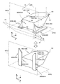
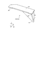
まず、実施形態に係るロボット10の概要について図1を用いて説明する。図1は、実施形態に係るロボット10の概要を示す図である。なお、図1では、ロボット10における基部10Bの形状を主に示しており、多関節アーム10ARについては取り付け部分を破線で示すにとどめ、具体的な形状の記載を省略している。なお、ロボット10全体の例については図9を用いて後述することとする。
First, an outline of the
また、図1には、説明をわかりやすくするために、鉛直上向きが正方向であるZ軸、基部10Bの背面側が負方向で正面側が正方向であるY軸を含む3次元の直交座標系を図示している。なお、X軸は基部10Bの背面側からみて「左側」を負方向、「右側」を正方向とする。以下では、「左側」または「右側」と記載することがある。また、かかる直交座標系は、以下の説明で用いる他の図面においても示す場合がある。
Further, in order to make the explanation easy to understand, FIG. 1 shows a three-dimensional Cartesian coordinate system including a Z-axis in which the vertical upward direction is a positive direction and a Y-axis in which the back side of the
図1に示すように、実施形態に係るロボット10における基部10Bは、本体部100と、一対のブラケット200(第1ブラケット200Aおよび第2ブラケット200B)とを含む。
As shown in FIG. 1, the
本体部100は、多関節アーム10ARの基端側を支持するとともに、設置面Sである床面SFまたは壁面SWに一対のブラケット200を介して固定される。一対のブラケット200は、本体部100の被支持面をそれぞれ支持するとともに、本体部100を設置面Sに対して固定する。なお、図1では、多関節アーム10ARを上面101で支持する場合を示したが、上面101以外で支持することとしてもよい。
The
このように、基部10Bは、一対のブラケット200を本体部100から分離し、一対のブラケット200をお互いに入れ替えて本体部100へ取り付けることで、設置面Sを床面SFまたは壁面SWに切り替える。
In this way, the
ここで、本体部100は、対向する側面102(側面102Aおよび側面102B)にブラケット200から支持される被支持面をそれぞれ有する。また、2つの被支持面は、それぞれ、YZ平面と平行である。つまり、2つの被支持面は、お互いに平行である。なお、図1には、壁面SW側の背面103、床面SF側の底面104を併せて示している。また、被支持面の具体例については図2等を用いて後述する。
Here, the
一方、一対のブラケット200は、本体部100の側面102における被支持面に固定される第1面201(図4参照)と、第1面201に垂直で設置面Sに固定される第2面202(図4参照)とを有している。また、一対のブラケット200は、第1面201同士を重ね合わせた姿勢において第1面201についてお互いに面対称な形状を有する。なお、第1面201および第2面202の詳細については図4等を用いて後述する。
On the other hand, the pair of
図1の上段には、本体部100の右側に第1ブラケット200Aを、左側に第2ブラケット200Bを、それぞれ固定することで、基部10Bを床面SFに設置可能とした基部10B1を示している。また、図1の下段には、本体部100の右側に第2ブラケット200Bを、左側に第1ブラケット200Aを、それぞれ固定することで、基部10Bを壁面SWに設置可能とした基部10B2を示している。
The upper part of FIG. 1 shows a base portion 10B1 in which the
また、本体部100および一対のブラケット200は、一対のブラケット200をお互いに入れ替え可能とする固定部500を備える。なお、固定部500の具体例については、図2、図4等を用いて後述する。
Further, the
まず、図1の上段に示した基部10B1について説明する。固定部500は、床面SFと壁面SWとの対称面PSに沿う第1向きD1に、本体部100と、一対のブラケット200との相対姿勢を拘束する。ここで、床面SFと壁面SWとの角度が90度の場合、床面SFと対称面PSとの角度αは、90度の半分である45度である。
First, the base portion 10B1 shown in the upper part of FIG. 1 will be described. The
このような第1向きD1とすることで、本体部100の被加工領域を背面103と底面104との角部に集約することができるので、本体部100の側面を有効利用することができる。たとえば、本体部100の側面におけるコネクタ等の配置領域を確保することができる。
By setting the first orientation D1 in this way, the work area of the
固定部500は、本体部100と一対のブラケット200との相対姿勢を第1向きD1に拘束する。なお、側面102A側が固定部500Aであり、側面102B側が固定部500Bである。
The
本実施形態では、第1向きD1が、図1に示した対称面PSに沿う場合について説明するが、床面SFと壁面SWとの対称面としては、図1に示した対称面PSの他に、対称面PSに垂直な面がある。したがって、第1向きを対称面PSに垂直な面に沿わせることとしてもよい。なお、この場合には、図1に示した角度αは、135度(45度+90度)となる。 In the present embodiment, the case where the first orientation D1 is along the symmetry plane PS shown in FIG. 1 will be described, but the symmetry plane between the floor surface SF and the wall surface SW is other than the symmetry plane PS shown in FIG. There is a plane perpendicular to the plane of symmetry PS. Therefore, the first orientation may be along the plane perpendicular to the plane of symmetry PS. In this case, the angle α shown in FIG. 1 is 135 degrees (45 degrees + 90 degrees).
次に、図1の下段に示した基部10B2について説明する。なお、上段に示した基部10B1で既に説明した内容については適宜省略する。また、基部10B2では、基部10B1に示した多関節アーム10ARの記載を省略している。 Next, the base portion 10B2 shown in the lower part of FIG. 1 will be described. The contents already described in the base portion 10B1 shown in the upper part will be omitted as appropriate. Further, in the base portion 10B2, the description of the articulated arm 10AR shown in the base portion 10B1 is omitted.
図1の下段に示したように、上段に示した一対のブラケット200を入れ替えると、設置面Sを、壁面SWとすることができる。つまり、設置面Sを床面SFから壁面SWへ切り替えることができる。また、再度、一対のブラケット200を入れ替えると、設置面Sを壁面SWから床面SFへ切り替えることができる。
As shown in the lower part of FIG. 1, by exchanging the pair of
このように、設置用の一対のブラケット200を本体部100から分離し、一対のブラケット200をお互いに入れ替えることで、本体部100の姿勢を保持しつつ、床面SFにも壁面SWにもロボット10を設置可能とすることができる。
In this way, by separating the pair of
また、本体部100の設置精度を高める加工面を、対向する側面102の被支持面に限定することができる。これにより、本体部100の形状の自由度を高めることが可能となり、本体部100の小型化を図ることができる。すなわち、基部10Bを小型化することができる。
Further, the processed surface for improving the installation accuracy of the
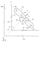
次に、基部10Bにおける本体部100の第1固定部110について、図2および図3を用いて説明する。図2は、基部10Bにおける本体部100の第1固定部110その1を示す側面図であり、図3は、その2を示す側面図である。
Next, the first fixing portion 110 of the
図2は、図1に示した本体部100をX軸正方向側からみた側面図に相当する。図2に示した第1固定部110については、第1固定部110Aのように、側面102A(図1参照)に対応する「A」を符号に付加する。また、第1固定部110Aを区別する場合には、通番を示す数字をさらに付加する。
FIG. 2 corresponds to a side view of the
図2に示すように、第1固定部110Aは、側面102AからX軸正方向側へ突出した突出部102aの被支持面102bに設けられる締結穴である。また、第1固定部110Aは、ピッチ線PLに沿って並んでいる。ピッチ線PLは、図1にも示した第1向きD1と平行である。ここで、ピッチ線PLの底面104に対する角度αは、45度である。
As shown in FIG. 2, the first fixing portion 110A is a fastening hole provided on the supported
なお、各第1固定部110Aの間隔(ピッチ)は、等間隔とすることができるが、各第1固定部110Aは、第1固定部110A列の対称線CLについて対称な位置にそれぞれ設けられていれば足りる。なお、対称線CLの底面104に対する角度β(=α+90度)は、135度である。また、対称線CLに沿う向きは、向きC1である。
The intervals (pitch) of the first fixed portions 110A can be equal, but the first fixed portions 110A are provided at positions symmetrical with respect to the symmetrical line CL of the first fixed portion 110A row. It's enough if you have it. The angle β (= α + 90 degrees) of the symmetry line CL with respect to the
突出部102aの端面は、YZ平面と平行となるように加工された被支持面102bである。また、突出部102aの周面には、被支持面102bと垂直な加工面を含んだ位置決め部102cが設けられる。位置決め部102cは、ブラケット200(図1参照)の取付精度を高めるために用いられる。また、位置決め部102cは、対称線CLについて対称な凸形状であり、先狭な一組の斜面102sを有する。なお、位置決め部102cとは反対側の周面には、ブラケット200の位置決めの際に押圧される被押圧面102dが設けられる。
The end surface of the protruding
なお、図2では、第1固定部110Aとして、第1固定部110A1、第1固定部110A2、第1固定部110A3および第1固定部110A4の4つの第1固定部110Aを例示したが、第1固定部110Aは対称線CLについて対称な位置にそれぞれ設けられることを条件として2つ以上の任意の個数とすることができる。なお、奇数個の場合には、真ん中の第1固定部110Aは対称線CL上に設けられることになる。 In FIG. 2, four first fixed portions 110A of the first fixed portion 110A1, the first fixed portion 110A2, the first fixed portion 110A3, and the first fixed portion 110A4 are illustrated as the first fixed portion 110A. 1 The number of fixed portions 110A can be any number of two or more, provided that they are provided at positions symmetrical with respect to the line of symmetry CL. In the case of an odd number, the first fixed portion 110A in the middle is provided on the symmetry line CL.
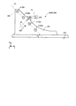
図3は、図1に示した本体部100をX軸負方向側からみた側面図に相当する。図3に示した第1固定部110については、第1固定部110Bのように、側面102B(図1参照)に対応する「B」を符号に付加する。また、第1固定部110Bを区別する場合には、通番を示す数字をさらに付加する。
FIG. 3 corresponds to a side view of the
図3に示すように、第1固定部110Bは、側面102BからX軸負方向側へ突出した突出部102aの被支持面102bに設けられる締結穴である。また、第1固定部110Bは、ピッチ線PLに沿って並んでいる。ピッチ線PLは、図1にも示した第1向きD1と平行である。ここで、ピッチ線PLの底面104に対する角度αは、45度である。
As shown in FIG. 3, the first fixing portion 110B is a fastening hole provided on the supported
なお、各第1固定部110の間隔(ピッチ)は、等間隔とすることができるが、各第1固定部110Bは、第1固定部110B列の対称線CLについて対称な位置にそれぞれ設けられていれば足りる。なお、対称線CLの角度β(=α+90度)は、135度である。また、対称線CLに沿う向きは、向きC1である。 The intervals (pitch) of the first fixed portions 110 can be equal, but the first fixed portions 110B are provided at positions symmetrical with respect to the symmetrical line CL of the first fixed portion 110B row. It's enough if you have it. The angle β (= α + 90 degrees) of the symmetry line CL is 135 degrees. The direction along the symmetry line CL is the direction C1.
突出部102aの端面は、YZ平面と平行となるように加工された被支持面102bである。また、突出部102aの周面には、被支持面102bと垂直な加工面を含んだ位置決め部102cが設けられている。位置決め部102cは、ブラケット200(図1参照)の取付精度を高めるために用いられる。また、位置決め部102cは、対称線CLについて対称な凸形状であり、先狭な一組の斜面102sを有する。なお、位置決め部102cとは反対側の周面には、ブラケット200の位置決めの際に押圧される被押圧面102dが設けられる。
The end surface of the protruding
なお、図3では、第1固定部110Bとして、第1固定部110B1、第1固定部110B2、第1固定部110B3および第1固定部110B4の4つの第1固定部110Bを例示した。しかしながら、第1固定部110Bは、図2に示した第1固定部110AとX軸に沿う向きにそれぞれ重なっていれば、第1固定部110Aの個数と同数とすることができる。 In FIG. 3, four first fixed portions 110B of the first fixed portion 110B1, the first fixed portion 110B2, the first fixed portion 110B3, and the first fixed portion 110B4 are illustrated as the first fixed portion 110B. However, the number of the first fixed portions 110B can be the same as the number of the first fixed portions 110A as long as they overlap the first fixed portions 110A shown in FIG. 2 in the direction along the X axis.
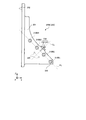
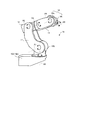
次に、床置き姿勢とした一対のブラケット200について、図4および図5を用いて説明する。図4は、床置き姿勢の第1ブラケット200Aを示す側面図であり、図5は、床置き姿勢の第2ブラケット200Bを示す側面図である。なお、図4および図5は、図1の上段に示した基部10B1における第1ブラケット200Aおよび第2ブラケット200Bの姿勢にそれぞれ対応する。また、図4および図5は、いずれもX軸正方向からみた側面図に相当し、本体部100(図1参照)および他方のブラケット200の記載については省略している。
Next, the pair of
図4に示すように、第1ブラケット200Aは、本体部100の被支持面102b(図2参照)に固定される第1面201と、第1面201に垂直で設置面Sである床面SFに固定される第2面202とを備える。なお、第1面201は、第1ブラケット200AにおけるX軸負方向側の面であり、第2面202は、第1ブラケット200AにおけるZ軸負方向側の面である。
As shown in FIG. 4, the
また、第1ブラケット200Aは、第2面202と角度α(45度)をなすピッチ線PLに沿い、図2に示した第1固定部110Aに対し、X軸に沿う向きにそれぞれ重なるように並んだ第2固定部210Aを備える。第2固定部210Aは、第1ブラケット200Aに対応する第2固定部210である。第2固定部210Aは、第1ブラケット200Aを貫通する貫通孔である。第2固定部210Aは、締結具300によって対応する第1固定部110Aに対してそれぞれ固定される。
Further, the
つまり、第2固定部210A1は第1固定部110A1に、第2固定部210A2は第1固定部110A2に、第2固定部210A3は第1固定部110A3に、第2固定部210A4は第1固定部110A4に、それぞれ固定される。 That is, the second fixed portion 210A1 is attached to the first fixed portion 110A1, the second fixed portion 210A2 is attached to the first fixed portion 110A2, the second fixed portion 210A3 is attached to the first fixed portion 110A3, and the second fixed portion 210A4 is attached to the first fixed portion 210A4. It is fixed to each of the portions 110A4.
また、第1ブラケット200Aは、図2に示した位置決め部102cに周面が接するように第1面201から突出した2つのピン220を備える。ここで、2つのピン220は、図2にも示した対称線CLについて対称な位置にそれぞれ設けられる。さらに、第1ブラケット200Aは、図2に示した被押圧面102dを押圧する押圧部230を備える。押圧部230は、ボルト231と、第1ブラケット200Aに固定されたベース232とを含む。
Further, the
ボルト231は、ベース232における対称線CLに沿うネジ孔を貫通しており、締め込むことで、図2に示した被押圧面102dを押圧する。つまり、上記した締結具300を仮止めした状態で、ボルト231を締め込むことで、2つのピン220の周面を、図2に示した位置決め部102cの一組の斜面102sにそれぞれ押し付けることができ、これにより、本体部100と第1ブラケット200Aとの位置合わせ精度を高めることができる。また、本体部100との位置合わせにピン220を用いることで、位置合わせを簡易な構成で行うことができる。
The
図5に示すように、第2ブラケット200Bは、本体部100の被支持面102b(図3参照)に固定される第1面201と、第1面201に垂直で設置面Sである床面SFに固定される第2面202とを備える。なお、第1面201は、第2ブラケット200BにおけるX軸正方向側の面であり、第2面202は、第2ブラケット200BにおけるZ軸負方向側の面である。
As shown in FIG. 5, the
また、第2ブラケット200Bは、第2面202と角度α(45度)をなすピッチ線PLに沿い、図3に示した第1固定部110Bに対し、X軸に沿う向きにそれぞれ重なるように並んだ第2固定部210Bを備える。第2固定部210Bは、第2ブラケット200Bに対応する第2固定部210である。第2固定部210Bは、第2ブラケット200Bを貫通する貫通孔である。第2固定部210Bは、締結具300によって対応する第1固定部110Bに対してそれぞれ固定される。
Further, the
つまり、第2固定部210B1は第1固定部110B1に、第2固定部210B2は第1固定部110B2に、第2固定部210B3は第1固定部110B3に、第2固定部210B4は第1固定部110B4に、それぞれ固定される。 That is, the second fixed portion 210B1 is attached to the first fixed portion 110B1, the second fixed portion 210B2 is attached to the first fixed portion 110B2, the second fixed portion 210B3 is attached to the first fixed portion 110B3, and the second fixed portion 210B4 is attached to the first fixed portion 210B4. Each is fixed to the portion 110B4.
また、第2ブラケット200Bは、図3に示した位置決め部102cに周面が接するように第1面201から突出した2つのピン220を備える。ここで、2つのピン220は、図3にも示した対称線CLについて対称な位置にそれぞれ設けられる。さらに、第2ブラケット200Bは、図3に示した被押圧面102dを押圧する押圧部230を備える。押圧部230は、ボルト231と、第2ブラケット200Bに固定されたベース232とを含む。
Further, the
ボルト231は、ベース232における対称線CLに沿うネジ孔を貫通しており、締め込むことで、図3に示した被押圧面102dを押圧する。つまり、上記した締結具300を仮止めした状態で、ボルト231を締め込むことで、2つのピン220の周面を、図3に示した位置決め部102cの一組の斜面102sにそれぞれ押し付けることができ、これにより、本体部100と第2ブラケット200Bとの位置合わせ精度を高めることができる。
The
次に、壁掛け姿勢とした一対のブラケット200について、図6および図7を用いて説明する。図6および図7は、第1ブラケット200Aと、第2ブラケット200Bをお互いに入れ替えている点で、図4および図5とは異なる。なお、以下では、図4および図5とは異なる点について主に記載することとする。
Next, a pair of
図6は、壁掛け姿勢の第2ブラケット200Bを示す側面図であり、図7は、壁掛け姿勢の第1ブラケット200Aを示す側面図である。なお、図6および図7は、図1の下段に示した基部10B2における第2ブラケット200Bおよび第1ブラケット200Aの姿勢にそれぞれ対応する。また、図6および図7は、いずれもX軸正方向からみた側面図に相当し、図4および図5と同様に本体部100(図1参照)および他方のブラケット200の記載については省略している。
FIG. 6 is a side view showing the
図6に示すように、第2ブラケット200Bは、本体部100における側面102Aにおける被支持面102b(図2参照)に第1面201が固定される。また、第2面202は、設置面Sである壁面SWに固定される。なお、第1面201は、第2ブラケット200BにおけるX軸負方向側を向き、第2面202は、Y軸負方向側を向く。
As shown in FIG. 6, in the
ここで、第2固定部210B4は第1固定部110A1に、第2固定部210B3は第1固定部110A2に、第2固定部210B2は第1固定部110A3に、第2固定部210B1は第1固定部110A4に、それぞれ固定される。 Here, the second fixed portion 210B4 is in the first fixed portion 110A1, the second fixed portion 210B3 is in the first fixed portion 110A2, the second fixed portion 210B2 is in the first fixed portion 110A3, and the second fixed portion 210B1 is in the first fixed portion 110A3. Each is fixed to the fixing portion 110A4.
図7に示すように、第1ブラケット200Aは、本体部100における側面102Bにおける被支持面102b(図3参照)に第1面201が固定される。また、第2面202は、設置面Sである壁面SWに固定される。なお、第1面201は、第1ブラケット200AにおけるX軸正方向側を向き、第2面202は、Y軸負方向側を向く。
As shown in FIG. 7, in the
ここで、第2固定部210A4は第1固定部110B1に、第2固定部210A3は第1固定部110B2に、第2固定部210A2は第1固定部110B3に、第2固定部210A1は第1固定部110B4に、それぞれ固定される。 Here, the second fixed portion 210A4 is attached to the first fixed portion 110B1, the second fixed portion 210A3 is attached to the first fixed portion 110B2, the second fixed portion 210A2 is attached to the first fixed portion 110B3, and the second fixed portion 210A1 is attached to the first fixed portion 110B1. Each is fixed to the fixing portion 110B4.
次に、ブラケット200における設置面S(図1参照)用の加工面について、図8を用いて説明する。図8は、ブラケット200の加工面を示す斜視図である。なお、図8には、第1ブラケット200Aを例示しているが、第2ブラケット200Bについては、第1面201同士を重ね合わせた場合に第1面201について面対称な形状であるので、説明を省略する。
Next, the machined surface for the installation surface S (see FIG. 1) of the
図8に示すように、ブラケット200は、第2面202を端面とする周面に第2面202と垂直でお互いに垂直な第3面203および第4面204を備える。ここで、図8には、お互いに独立した2つの第3面203を示しているが、2つの第3面203は、YZ平面と平行な1つの平面に含まれる。また、第4面204は、XZ平面と平行な平面に含まれる。
As shown in FIG. 8, the
ここで、2つの第3面203は、ブラケット200のX軸座標の位置合わせに用いられ、第4面204は、ブラケット200のY軸座標の位置合わせに用いられる。このように、第2面202と垂直な向きにも設置精度を高める加工面を設けることで、設置面Sに対するブラケット200の位置合わせ精度を高めることができる。
Here, the two
また、図8に示したように、第3面203および第4面204を、第2面202を端面とする周面の全面ではなく、一部にそれぞれ設けることで、加工面の加工面積を削減することができ、加工コストを抑えることができる。
Further, as shown in FIG. 8, the processed area of the processed surface is increased by providing the
次に、基部10Bを備えるロボット10の例について図9を用いて説明する。図9は、ロボット10の斜視図である。図9に示すように、ロボット10は、旋回軸A0〜第5軸A5の6軸を有するいわゆる垂直多関節ロボットである。このように、ロボット10は、6軸のロボットであるので、先端の位置について3つの自由度を有し、先端の向きについて3つの自由度を有する。つまり、先端を3次元の任意の位置、かつ、3次元の任意の向きに自由に変更することができる。
Next, an example of the
図9に示したように、ロボット10は、基端側から先端側へ向けて、図1等に示した基部10B(ブラケット200を省略しているので本体部100のみを図示)と、旋回部10Sと、第1アーム11と、第2アーム12と、第3アーム13と、手首部14とを備える。ここで、旋回部10S〜手首部14は、図1に示した多関節アーム10ARに相当する。また、手首部14の先端側には、作業用の任意のツールを着脱可能に取り付けることができる。
As shown in FIG. 9, the
なお、「アーム」の概念には、第1アーム11、第2アーム12および第3アーム13に加えて手首部14や旋回部10Sも含まれるものとする。つまり、ロボット10において回転や旋回などの可動部位を「アーム」と呼ぶことができる。
The concept of "arm" includes the
基部10Bは、図1等を用いて詳細に説明したのでここでの説明を省略する。旋回部10Sは、基部10Bに支持され、鉛直向きの旋回軸A0まわりに旋回する。第1アーム11は、基端側が旋回部10Sに支持され、旋回軸A0と垂直な第1軸A1まわりに旋回する。第2アーム12は、基端側が第1アーム11の先端側に支持され、第1軸A1と平行な第2軸A2まわりに旋回する。
Since the
第3アーム13は、基端側が第2アーム12の先端側に支持され、第2軸A2と垂直な第3軸A3まわりに回転する。手首部14は、旋回部14aと、回転部14bとを含む。旋回部14aは、基端側が第3アーム13の先端側に支持され、第3軸A3と垂直な第4軸A4まわりに旋回する。
The base end side of the
回転部14bは、基端側が旋回部14aの先端側に支持され、第4軸A4と直交する第5軸A5まわりに回転する。また、回転部14bの先端側には、上記したツール等を取り付けることができる。なお、旋回部14aおよび回転部14bは中空であり、ツールに接続するケーブルやチューブ等がかかる中空部分に挿通される。これにより、手首部14まわりにケーブル等を配索する必要がないので、ロボット10の作業性を向上させることができる。
The base end side of the
なお、図9に示したロボット10は、一例であり、図1等に示した基部10Bは、あらゆる軸数や軸構成の多関節アーム10ARに適用することができる。
The
上述してきたように、実施形態に係るロボット10は、多関節アーム10ARと、基部10Bとを備える。基部10Bは、多関節アーム10ARの基端側を支持するとともに、設置面Sである床面SFまたは壁面SWに固定される。基部10Bは、本体部100と、一対のブラケット200とを備える。本体部100は、多関節アーム10ARの基端側を支持するとともに、対向する側面102に被支持面102bをそれぞれ有する。
As described above, the
また、一対のブラケット200は、本体部100の被支持面102bをそれぞれ支持するとともに、本体部100を設置面Sに対して固定する。本体部100および一対のブラケット200は、一対のブラケット200をお互いに入れ替えて本体部100へ取り付けることで、設置面Sを床面SFまたは壁面SWに切り替え可能な固定部500をそれぞれ備える。
Further, the pair of
このように、ロボットは、基部を本体部と、一対のブラケットとに分離した。したがって、一対のブラケットを入れ替えることにより、本体部の姿勢を変更することなく、設置面を床面にも壁面にも切り替えることを可能としたうえで、基部を小型化したロボットを提供することができる。 In this way, the robot separated the base portion into a main body portion and a pair of brackets. Therefore, by exchanging the pair of brackets, it is possible to switch the installation surface to the floor surface or the wall surface without changing the posture of the main body, and it is possible to provide a robot with a miniaturized base. it can.
なお、上述した実施形態では、設置面を床面と壁面とで切り替えるロボットを示したが、設置面を天面と壁面とで切り替えることとしてもよい。また、上述した実施形態では、壁面と床面とが垂直である場合を示したが、壁面と床面とが垂直でない場合でも、上記した第1向きを壁面と床面との対称面に沿う向きとしていれば、そのまま上記したロボットを適用することができる。 In the above-described embodiment, the robot that switches the installation surface between the floor surface and the wall surface is shown, but the installation surface may be switched between the top surface and the wall surface. Further, in the above-described embodiment, the case where the wall surface and the floor surface are vertical is shown, but even when the wall surface and the floor surface are not vertical, the above-mentioned first direction is along the plane of symmetry between the wall surface and the floor surface. If the orientation is set, the above-mentioned robot can be applied as it is.
さらに、上述した実施形態では、固定部の例として、本体部の第1固定部を第1向きの穴列とするとともに、ブラケットの第2固定部を第1向きの貫通孔列とし、締結具で本体部とブラケットとを固定する場合を示した。しかしながら、これに限らず、たとえば、穴、ピン、埋め込みボルト等の公知のバリエーションで両者を固定することとしてもよい。また、たとえば、固定部を第1向きの凹部や凸部とし、これらを嵌め合うことで、本体部とブラケットとを固定することとしてもよい。 Further, in the above-described embodiment, as an example of the fixing portion, the first fixing portion of the main body portion has a first-facing hole row, and the second fixing portion of the bracket has a first-facing through-hole row. The case where the main body and the bracket are fixed is shown in. However, the present invention is not limited to this, and both may be fixed by known variations such as holes, pins, and embedded bolts. Further, for example, the fixing portion may be a first-facing concave portion or a convex portion, and these may be fitted to fix the main body portion and the bracket.
さらなる効果や変形例は、当業者によって容易に導き出すことができる。このため、本発明のより広範な態様は、以上のように表しかつ記述した特定の詳細および代表的な実施例に限定されるものではない。したがって、添付の特許請求の範囲およびその均等物によって定義される総括的な発明の概念の精神または範囲から逸脱することなく、様々な変更が可能である。 Further effects and variations can be easily derived by those skilled in the art. For this reason, the broader aspects of the invention are not limited to the particular details and representative examples described and described above. Therefore, various modifications can be made without departing from the spirit or scope of the general concept of the invention as defined by the appended claims and their equivalents.
10 ロボット
10AR 多関節アーム
10B 基部
10S 旋回部
11 第1アーム
12 第2アーム
13 第3アーム
14 手首部
14a 旋回部
14b 回転部
100 本体部
101 上面
102 側面
102a 突出部
102b 被支持面
102c 位置決め部
102d 被押圧面
103 背面
104 底面
110 第1固定部
200 ブラケット
201 第1面
202 第2面
203 第3面
204 第4面
210 第2固定部
220 ピン
230 押圧部
231 ボルト
232 ベース
300 締結具
500 固定部
A0 旋回軸
A1 第1軸
A2 第2軸
A3 第3軸
A4 第4軸
A5 第5軸
CL 対称線
D1 第1向き
PL ピッチ線
S 設置面
SF 床面
SW 壁面
10 Robot 10AR Articulated
Claims (9)
前記多関節アームの基端側を支持するとともに、設置面である床面または壁面に固定される基部と
を備え、
前記基部は、
前記多関節アームの前記基端側を支持するとともに、対向する側面に被支持面をそれぞれ有する本体部と、
前記本体部の前記被支持面をそれぞれ支持するとともに、前記本体部を前記設置面に対して固定する一対のブラケットと
を備え、
前記本体部および前記一対のブラケットは、
前記一対のブラケットをお互いに入れ替えて前記本体部へ取り付けることで、前記設置面を前記床面または前記壁面に切り替え可能な固定部をそれぞれ備えること
を特徴とするロボット。 With an articulated arm,
It is provided with a base portion that supports the base end side of the articulated arm and is fixed to a floor surface or a wall surface that is an installation surface.
The base is
A main body that supports the base end side of the articulated arm and has supported surfaces on opposite side surfaces, respectively.
Each of the supported surfaces of the main body is supported, and a pair of brackets for fixing the main body to the installation surface are provided.
The main body and the pair of brackets
A robot characterized in that a fixing portion capable of switching the installation surface to the floor surface or the wall surface is provided by replacing the pair of brackets with each other and attaching the robot to the main body portion.
前記床面および前記壁面の対称面に沿う第1向きに並ぶ複数の第1固定部を前記被支持面にそれぞれ有し、
前記一対のブラケットは、
前記本体部の前記被支持面に固定される第1面と、
前記第1面に垂直で前記設置面に固定される第2面と、
前記第1面に設けられ、前記第1向きに並ぶとともに前記複数の第1固定部にそれぞれ固定される複数の第2固定部と
をそれぞれ有すること
を特徴とする請求項1に記載のロボット。 The main body
Each of the supported surfaces has a plurality of first fixed portions arranged in a first direction along a symmetrical surface of the floor surface and the wall surface.
The pair of brackets
A first surface fixed to the supported surface of the main body,
A second surface perpendicular to the first surface and fixed to the installation surface,
The robot according to claim 1, further comprising a plurality of second fixing portions provided on the first surface, arranged in the first direction, and fixed to the plurality of first fixing portions, respectively.
前記第1向きに並んだ複数の締結穴であり、
前記第2固定部は、
前記複数の締結穴に対応する複数の貫通孔であり、
前記貫通孔を貫通し、前記締結穴を介して前記本体部と前記ブラケットとを締結する締結具を備えること
を特徴とする請求項2に記載のロボット。 The first fixing portion is
A plurality of fastening holes arranged in the first direction.
The second fixing portion is
A plurality of through holes corresponding to the plurality of fastening holes.
The robot according to claim 2, further comprising a fastener that penetrates the through hole and fastens the main body and the bracket through the fastening hole.
前記床面からみて上り傾斜し、前記壁面からみて下り傾斜する向きであること
を特徴とする請求項3に記載のロボット。 The first orientation is
The robot according to claim 3, wherein the robot has an upward inclination when viewed from the floor surface and a downward inclination when viewed from the wall surface.
前記対向する側面からそれぞれ突出した突出部に前記被支持面をそれぞれ備え、
前記突出部は、
前記被支持面と垂直な周面に前記ブラケットの位置決め部を備えること
を特徴とする請求項4に記載のロボット。 The main body
The supported surface is provided on each of the projecting portions protruding from the facing side surfaces.
The protrusion is
The robot according to claim 4, wherein a positioning portion of the bracket is provided on a peripheral surface perpendicular to the supported surface.
前記位置決め部に周面が接するように前記第1面から突出した複数のピンを備えること
を特徴とする請求項5に記載のロボット。 The bracket
The robot according to claim 5, further comprising a plurality of pins protruding from the first surface so that the peripheral surface is in contact with the positioning portion.
前記第1向きに並ぶ前記締結穴の列の対称線について対称な斜面を有する凸形状であり、 前記ブラケットは、
前記第1向きに並ぶ2つのピンを前記凸形状を挟む位置に有しており、
前記対称線に沿って前記位置決め部へ向かう向きに前記本体部を押圧する押圧部
を備えることを特徴とする請求項6に記載のロボット。 The positioning unit is
The bracket has a convex shape having a slope symmetrical with respect to the line of symmetry of the row of fastening holes arranged in the first direction.
The two pins arranged in the first direction are held at positions sandwiching the convex shape.
The robot according to claim 6, further comprising a pressing portion that presses the main body portion in a direction toward the positioning portion along the line of symmetry.
前記第2面を端面とする周面に前記第2面と垂直でお互いに垂直な第3面および第4面を有すること
を特徴とする請求項2〜7のいずれか一つに記載のロボット。 The bracket
The robot according to any one of claims 2 to 7, wherein the peripheral surface having the second surface as an end surface has a third surface and a fourth surface perpendicular to the second surface and perpendicular to each other. ..
お互いに垂直であること
を特徴とする請求項1〜8のいずれか一つに記載のロボット。 The floor surface and the wall surface
The robot according to any one of claims 1 to 8, wherein the robot is perpendicular to each other.
Priority Applications (5)
| Application Number | Priority Date | Filing Date | Title |
|---|---|---|---|
| JP2018215254A JP6889826B2 (en) | 2018-11-16 | 2018-11-16 | robot |
| CN201910998484.6A CN111195900B (en) | 2018-11-16 | 2019-10-21 | robot |
| KR1020190133927A KR102336093B1 (en) | 2018-11-16 | 2019-10-25 | Robot and method for mounting a rotbot on a mounting surface |
| EP19208277.4A EP3659756B1 (en) | 2018-11-16 | 2019-11-11 | Robot |
| US16/681,853 US11326737B2 (en) | 2018-11-16 | 2019-11-13 | Robot |
Applications Claiming Priority (1)
| Application Number | Priority Date | Filing Date | Title |
|---|---|---|---|
| JP2018215254A JP6889826B2 (en) | 2018-11-16 | 2018-11-16 | robot |
Publications (2)
| Publication Number | Publication Date |
|---|---|
| JP2020082216A JP2020082216A (en) | 2020-06-04 |
| JP6889826B2 true JP6889826B2 (en) | 2021-06-18 |
Family
ID=68536731
Family Applications (1)
| Application Number | Title | Priority Date | Filing Date |
|---|---|---|---|
| JP2018215254A Active JP6889826B2 (en) | 2018-11-16 | 2018-11-16 | robot |
Country Status (5)
| Country | Link |
|---|---|
| US (1) | US11326737B2 (en) |
| EP (1) | EP3659756B1 (en) |
| JP (1) | JP6889826B2 (en) |
| KR (1) | KR102336093B1 (en) |
| CN (1) | CN111195900B (en) |
Family Cites Families (18)
| Publication number | Priority date | Publication date | Assignee | Title |
|---|---|---|---|---|
| JPS4835732U (en) * | 1971-08-31 | 1973-04-28 | ||
| JPS6114880A (en) * | 1984-06-27 | 1986-01-23 | 三菱電機株式会社 | Fixing device for industrial robot |
| JP2538953B2 (en) * | 1987-11-17 | 1996-10-02 | 三菱重工業株式会社 | Balance mechanism of industrial robot |
| JPH023390U (en) * | 1988-06-16 | 1990-01-10 | ||
| US5102081A (en) * | 1991-03-15 | 1992-04-07 | Barchus David D | Telescopable pivotal mounting assembly |
| JP3041816B1 (en) * | 1999-04-14 | 2000-05-15 | 日通工株式会社 | Mechanism for adjusting the angle of the tabletop device and hanging it on the wall |
| US7267315B2 (en) * | 2005-08-29 | 2007-09-11 | Universal Scientific Industrial Co., Ltd. | Assembled type of display apparatus |
| TW200809305A (en) * | 2006-08-09 | 2008-02-16 | Benq Corp | Support structure for supporting an object |
| JP4889410B2 (en) * | 2006-08-29 | 2012-03-07 | ナカ工業株式会社 | Handrail bracket |
| JP5187182B2 (en) * | 2008-12-18 | 2013-04-24 | セイコーエプソン株式会社 | Articulated robot |
| JP5890653B2 (en) * | 2011-10-28 | 2016-03-22 | 川崎重工業株式会社 | Multi-axis robot |
| JP2016190294A (en) | 2015-03-31 | 2016-11-10 | セイコーエプソン株式会社 | Robot system |
| JP5983809B2 (en) * | 2015-04-01 | 2016-09-06 | セイコーエプソン株式会社 | Vertical articulated robot and robot cell |
| JP3202483U (en) * | 2015-11-26 | 2016-02-04 | ホームインテリアワソー株式会社 | Flat screen TV fixture |
| ITUB20159241A1 (en) * | 2015-12-23 | 2017-06-23 | Comau Spa | Multi-axis industrial robot, in particular of the SCARA type |
| JP6831198B2 (en) * | 2016-09-14 | 2021-02-17 | 株式会社ダイヘン | Industrial robot |
| EP3512450A4 (en) * | 2016-09-16 | 2020-11-04 | Mobius Imaging LLC | SYSTEM AND METHOD OF ASSEMBLING A ROBOTIC ARM IN A SURGICAL ROBOTIC SYSTEM |
| JP6677190B2 (en) | 2017-02-09 | 2020-04-08 | 株式会社安川電機 | Painting system and fixed operating robot |
-
2018
- 2018-11-16 JP JP2018215254A patent/JP6889826B2/en active Active
-
2019
- 2019-10-21 CN CN201910998484.6A patent/CN111195900B/en active Active
- 2019-10-25 KR KR1020190133927A patent/KR102336093B1/en active Active
- 2019-11-11 EP EP19208277.4A patent/EP3659756B1/en active Active
- 2019-11-13 US US16/681,853 patent/US11326737B2/en active Active
Also Published As
| Publication number | Publication date |
|---|---|
| EP3659756A1 (en) | 2020-06-03 |
| CN111195900A (en) | 2020-05-26 |
| CN111195900B (en) | 2023-04-14 |
| US20200158279A1 (en) | 2020-05-21 |
| US11326737B2 (en) | 2022-05-10 |
| JP2020082216A (en) | 2020-06-04 |
| KR20200057622A (en) | 2020-05-26 |
| KR102336093B1 (en) | 2021-12-06 |
| EP3659756B1 (en) | 2024-08-21 |
Similar Documents
| Publication | Publication Date | Title |
|---|---|---|
| US10821613B2 (en) | Robot | |
| US10744637B2 (en) | Robot | |
| US10150217B2 (en) | Tool adapter for robot wrist and robot with tool adapter attached thereto | |
| JP6889826B2 (en) | robot | |
| JP5177835B2 (en) | Double-arm robot manipulator | |
| CN118578415A (en) | Accessory mounting systems for robots | |
| JP7028330B2 (en) | robot | |
| CN108858173B (en) | Robot, robot control device, and robot system | |
| JP2002116101A (en) | Tactile sensors and sensor unit combining these sensor | |
| KR20200057621A (en) | Robot and method for connecting cables to a robot | |
| CN220128829U (en) | Connectors and robots for robots | |
| US20260054376A1 (en) | Vertical multi-joint robot wrist axis fastening structure | |
| JP5360283B2 (en) | Horizontal articulated robot | |
| JP2012240180A (en) | Double-arm robot | |
| CN116968007A (en) | Continuum robot | |
| JP2647700B2 (en) | Mechanical parts of industrial robot | |
| JP6638327B2 (en) | robot | |
| JP7706335B2 (en) | Parallel link mechanism and link actuator | |
| JP2015060583A (en) | Fire sensor attachment/detachment tool, and adaptor | |
| TW202440289A (en) | Cable Fixing Device | |
| JP2001176341A (en) | Supporter for assembling wire harness | |
| WO2026083575A1 (en) | Robot hand | |
| KR20230063176A (en) | Rotatable multi-axial shaft holder assembly | |
| JP6648491B2 (en) | Control devices, robots and robot systems | |
| JP2023135319A (en) | modular structure robot |
Legal Events
| Date | Code | Title | Description |
|---|---|---|---|
| A621 | Written request for application examination |
Free format text: JAPANESE INTERMEDIATE CODE: A621 Effective date: 20200706 |
|
| A977 | Report on retrieval |
Free format text: JAPANESE INTERMEDIATE CODE: A971007 Effective date: 20210413 |
|
| TRDD | Decision of grant or rejection written | ||
| A01 | Written decision to grant a patent or to grant a registration (utility model) |
Free format text: JAPANESE INTERMEDIATE CODE: A01 Effective date: 20210420 |
|
| A61 | First payment of annual fees (during grant procedure) |
Free format text: JAPANESE INTERMEDIATE CODE: A61 Effective date: 20210503 |
|
| R150 | Certificate of patent or registration of utility model |
Ref document number: 6889826 Country of ref document: JP Free format text: JAPANESE INTERMEDIATE CODE: R150 |
|
| R250 | Receipt of annual fees |
Free format text: JAPANESE INTERMEDIATE CODE: R250 |
|
| R250 | Receipt of annual fees |
Free format text: JAPANESE INTERMEDIATE CODE: R250 |