JP6888991B2 - Discharge cap - Google Patents
Discharge cap Download PDFInfo
- Publication number
- JP6888991B2 JP6888991B2 JP2017051534A JP2017051534A JP6888991B2 JP 6888991 B2 JP6888991 B2 JP 6888991B2 JP 2017051534 A JP2017051534 A JP 2017051534A JP 2017051534 A JP2017051534 A JP 2017051534A JP 6888991 B2 JP6888991 B2 JP 6888991B2
- Authority
- JP
- Japan
- Prior art keywords
- discharge
- container
- valve
- cap
- flow path
- Prior art date
- Legal status (The legal status is an assumption and is not a legal conclusion. Google has not performed a legal analysis and makes no representation as to the accuracy of the status listed.)
- Active
Links
Images


Landscapes
- Closures For Containers (AREA)
Description
本発明は、容器口部に嵌合され、容器内部に収容された内容物を傾斜させて吐出する吐出キャップに関する。 The present invention relates to a discharge cap that is fitted to a container mouth and that tilts and discharges the contents contained in the container.
従来、容器内部に収容された液状内容物または粘性を有する流動性内容物を傾斜させて吐出する吐出キャップとして、容器内部と吐出口(吐出通路24)との間に逆止弁が設けられている吐出キャップが公知である。この吐出キャップは、容器から内容物を吐出する際に、容器の外部から加圧された内容物が逆止弁を弁座から離脱させることで、容器内部から吐出口(吐出通路24)へ内容物が通過し吐出するとともに、内容物への加圧を解除することで、逆止弁が弁座に密着し容器を密閉するため、容器内部を外気から遮断でき、容器内部に残っている内容物の乾燥や酸化等の劣化を防ぐことができる。 Conventionally, a check valve is provided between the inside of the container and the discharge port (discharge passage 24) as a discharge cap for tilting and discharging the liquid content or the viscous fluid content contained in the container. The discharge cap is known. When the contents are discharged from the container, the contents pressurized from the outside of the container release the check valve from the valve seat, so that the contents of the discharge cap are released from the inside of the container to the discharge port (discharge passage 24). By releasing the pressure on the contents as well as passing the objects, the check valve comes into close contact with the valve seat and seals the container, so the inside of the container can be shut off from the outside air and the contents remaining inside the container. It is possible to prevent deterioration such as drying and oxidation of the product.
また、特許文献1等で公知の吐出キャップは、内容物を収容する可撓性の内部容器と、内部容器を内包する弾性を備えた外部容器とを有し、内部容器と外部容器との間に外気を吸引可能な吸入弁が設けられた容器を使用しており、内容物の吐出に伴い減少した外部容器内の体積を、吸入弁から外気を吸引することで復元できるため、容器の外観形状を変えることなく最後まで同じ使用感で内容物を吐出することができる。
しかしながら、上記特許文献1の吐出キャップでは、内容物の吐出後に逆止弁が作動して内部容器を密閉するため、吐出口(吐出通路24)から逆止弁までの空間に内容物が残留してしまう虞があった。
Further, the discharge cap known in Patent Document 1 and the like has a flexible inner container for accommodating the contents and an elastic outer container containing the inner container, and is between the inner container and the outer container. A container equipped with a suction valve capable of sucking outside air is used, and the volume inside the external container, which has decreased due to the discharge of the contents, can be restored by sucking outside air from the suction valve, so the appearance of the container The contents can be discharged with the same feeling of use until the end without changing the shape.
However, in the discharge cap of Patent Document 1, since the check valve operates after the contents are discharged to seal the internal container, the contents remain in the space from the discharge port (discharge passage 24) to the check valve. There was a risk that it would end up.
また、特許文献2にも容器内部の密閉性が高められた吐出キャップが提案されている。この吐出キャップは、弁座に浅い溝が形成されており、内容物の吐出後に逆止弁が作動しても、逆止弁と弁座との間に微小な隙間(流通溝27)が残る。
この時、外部容器が形状を復元していく間は外部容器内は負圧状態であるため、吸入弁から外気を吸引し終わるまでの間、吐出口から逆止弁までの空間に残留している内容物は逆止弁と弁座との間の微小な隙間(流通溝27)を通り、内部容器へ吸引、回収される。さらに、逆止弁と弁座との間の微小な隙間(流通溝27)は十分に薄いため、内部容器へ吸引された残液の一部が表面張力により逆止弁と弁座との間の隙間(流通溝27)に留まり、内部容器内への外気の進入を防止できる。
Further, Patent Document 2 also proposes a discharge cap having an improved airtightness inside the container. This discharge cap has a shallow groove formed in the valve seat, and even if the check valve operates after discharging the contents, a minute gap (distribution groove 27) remains between the check valve and the valve seat. ..
At this time, since the inside of the outer container is in a negative pressure state while the shape of the outer container is restored, it remains in the space from the discharge port to the check valve until the outside air is sucked from the suction valve. The contents are sucked and collected in the inner container through a minute gap (circulation groove 27) between the check valve and the valve seat. Further, since the minute gap (flow groove 27) between the check valve and the valve seat is sufficiently thin, a part of the residual liquid sucked into the internal container is between the check valve and the valve seat due to surface tension. It stays in the gap (circulation groove 27) and can prevent the outside air from entering the inner container.
しかしながら、特許文献2の吐出キャップにおいては、未だ改善の余地があった。即ち、逆止弁と弁座との当接面に浅い溝を設けて内容物が通過可能な微小な隙間(流通溝27)を形成するため、逆止弁が弁座と当接する位置関係にズレが生じた場合、隙間(流通溝27)の大きさが変化すると、隙間(流通溝27)が小さくなり過ぎて容器内部に十分に内容物を回収できなくなったり、隙間(流通溝27)が大きくなり過ぎて逆止弁が確実に作動せず、容器内部に空気を混入させてしまう虞があった。
また、特許文献2における円筒状内側壁部19と環状壁部10との接続部周辺のように吐出口(吐出通路41)から逆止弁までの空間に弁座の上端よりも低い箇所がある場合、残留した内容物を十分に容器内部に回収できずに残留してしまう虞があった。
また、微小な隙間(流通溝27)の形成領域は逆止弁と弁座との間に限定されるため、高粘度液等の流動しにくい内容物を回収したい場合、逆止弁と弁座との間に形成した微小な隙間(流通溝27)だけでは流量が十分に確保できずに内容物を容器内部へ回収しきれない虞があった。
さらに、容器内部に収容された内容物を傾斜させて吐出するため、内容物の吐出時に、吐出口(吐出通路41)から逆止弁までの空間が傾斜した際の上方に流入してきた空気が溜まりやすく、逆止弁と弁座との間に形成した隙間(流通溝27)に空気が入り込み、容器内部へ空気が流入してしまう虞があった。
However, there is still room for improvement in the discharge cap of Patent Document 2. That is, since a shallow groove is provided on the contact surface between the check valve and the valve seat to form a minute gap (circulation groove 27) through which the contents can pass, the check valve is in a positional relationship of contact with the valve seat. If the size of the gap (distribution groove 27) changes when the gap occurs, the gap (distribution groove 27) becomes too small and the contents cannot be sufficiently collected inside the container, or the gap (distribution groove 27) becomes open. It became too large and the check valve did not operate reliably, and there was a risk that air would be mixed inside the container.
Further, there is a portion lower than the upper end of the valve seat in the space from the discharge port (discharge passage 41) to the check valve, such as around the connection portion between the cylindrical inner side wall portion 19 and the annular wall portion 10 in Patent Document 2. In that case, there is a risk that the remaining contents cannot be sufficiently recovered inside the container and remain.
Further, since the region where a minute gap (flow groove 27) is formed is limited between the check valve and the valve seat, when it is desired to collect contents that are difficult to flow such as a high-viscosity liquid, the check valve and the valve seat There is a risk that the flow rate cannot be sufficiently secured only by the minute gap (distribution groove 27) formed between the two and the contents, and the contents cannot be completely collected inside the container.
Further, since the contents contained in the container are inclined and discharged, the air flowing upward when the space from the discharge port (discharge passage 41) to the check valve is inclined at the time of discharging the contents is discharged. It is easy to collect, and there is a possibility that air may enter the gap (flow groove 27) formed between the check valve and the valve seat, and the air may flow into the container.
本発明は、これらの問題点を解決するものであり、簡単な構成で、内容物回収のための流路形状を一定に保ち、吐出口から逆止弁までの空間に残留した内容物を容器内部へ十分に回収できるとともに、逆止弁を確実に作動でき、容器内へ空気が流入することがない吐出キャップを提供することを目的とするものである。 The present invention solves these problems. With a simple configuration, the shape of the flow path for collecting the contents is kept constant, and the contents remaining in the space from the discharge port to the check valve are containerized. It is an object of the present invention to provide a discharge cap which can be sufficiently recovered to the inside, the check valve can be operated reliably, and air does not flow into the container.
本発明の吐出キャップは、容器口部に嵌合され、容器内部に収容された内容物を傾斜させて吐出する吐出キャップであって、前記吐出キャップは、容器口部と嵌合する嵌合部と、容器内部に収容された内容物を吐出する吐出口とを有するとともに、容器内部と前記吐出口との間に区画された弁室をさらに有し、前記弁室には、容器内部と連通し、内容物を取り出す供給孔及び弁座を有する底部と、逆止弁と、前記弁室と容器内部とを連通する少なくとも1つの回収流路とが設けられ、前記逆止弁は前記供給孔の軸線方向に沿って摺動可能に設けられるとともに、前記弁座方向に付勢されて前記弁座と当接可能に構成され、前記回収流路は、少なくとも前記弁座よりも外周側で、かつ、吐出時に傾斜した際の前記弁室内の内容物の液面よりも下方の位置にのみ設けられ、前記吐出キャップには、前記吐出口を閉塞する閉塞栓を有した上蓋が設けられ、前記閉塞栓は、前記上蓋を閉じた際に、前記逆止弁を押圧することにより、前記課題を解決するものである。
また、本発明の吐出キャップは、容器口部に嵌合され、容器内部に収容された内容物を傾斜させて吐出する吐出キャップであって、前記吐出キャップは、キャップ本体と中栓とを有し、前記吐出キャップは、容器口部と嵌合する嵌合部と、容器内部に収容された内容物を吐出する吐出口とを有するとともに、容器内部と前記吐出口との間に区画された弁室をさらに有し、前記弁室には、容器内部と連通し、内容物を取り出す供給孔及び弁座を有する底部と、逆止弁と、前記弁室と容器内部とを連通する少なくとも1つの回収流路とが設けられ、前記逆止弁は前記供給孔の軸線方向に沿って摺動可能に設けられるとともに、前記弁座方向に付勢されて前記弁座と当接可能に構成され、前記回収流路は、少なくとも前記弁座よりも外周側で、かつ、吐出時に傾斜した際の前記弁室内の内容物の液面よりも下方の位置にのみ設けられ、前記キャップ本体には、前記キャップ本体の本体天面から上方に突出した前記吐出口と、前記本体天面の下面から円筒状に垂下した係合壁部とが設けられ、前記中栓には、前記供給孔および前記弁座を有した前記底部が設けられ、前記弁室は、前記係合壁部に前記中栓が嵌合することで形成され、前記中栓と前記係合壁部の間には、前記回収流路が設けられていることにより、前記課題を解決するものである。
Discharge cap of the present invention is fitted to the container mouth portion, a discharge cap which discharges by tilting the contents contained in the container, the discharge cap fitting portion to be fitted to the container mouth portion And a discharge port for discharging the contents contained in the container, and further having a valve chamber partitioned between the inside of the container and the discharge port, and the valve chamber communicates with the inside of the container. A bottom having a supply hole and a valve seat for taking out the contents, a check valve, and at least one recovery flow path communicating the valve chamber and the inside of the container are provided, and the check valve has the supply hole. It is provided so as to be slidable along the axial direction of the valve seat, and is configured to be urged in the valve seat direction so as to come into contact with the valve seat. In addition, the discharge cap is provided only at a position below the liquid level of the contents in the valve chamber when it is tilted at the time of discharge, and the discharge cap is provided with an upper lid having a closing plug for closing the discharge port. The obstruction plug solves the problem by pressing the check valve when the upper lid is closed.
Further, the discharge cap of the present invention is a discharge cap that is fitted to the container mouth and discharges the contents contained in the container at an angle, and the discharge cap has a cap body and an inner plug. The discharge cap has a fitting portion that fits with the container mouth portion and a discharge port that discharges the contents contained in the container, and is partitioned between the inside of the container and the discharge port. The valve chamber further has a valve chamber, and the valve chamber communicates with the inside of the container and has a bottom having a supply hole and a valve seat for taking out the contents, a check valve, and at least one communicating with the inside of the valve chamber and the inside of the container. The check valve is provided so as to be slidable along the axial direction of the supply hole, and is urged in the valve seat direction so as to be in contact with the valve seat. The recovery flow path is provided at least on the outer peripheral side of the valve seat and at a position below the liquid level of the contents in the valve chamber when tilted at the time of discharge. The discharge port protruding upward from the top surface of the main body of the cap body and an engaging wall portion cylindrically hung from the lower surface of the top surface of the main body are provided, and the inner plug has the supply hole and the valve. The bottom portion having a seat is provided, and the valve chamber is formed by fitting the inner plug into the engaging wall portion, and the recovery flow is provided between the inner plug and the engaging wall portion. By providing the road, the above-mentioned problem is solved.
請求項1に係る吐出キャップ及び、回収流路は、少なくとも弁座よりも外周側に設けられているため、逆止弁と弁座との当接位置に依存することなく、内容物回収のための流路を常に一定に保つことができるとともに、逆止弁を確実に作動させることができる。
また、弁座上に回収流路を設ける場合に比べて、容器口部よりも内側且つ弁座よりも外側に回収流路を設けた方が、回収流路の総断面積をより大きくできる。即ち、高粘度液等の流動しにくい内容物に対しても迅速に容器内部へ回収可能な回収流路を形成することができる。
さらに、回収流路は、吐出時に傾斜した際の弁室内の内容物の液面よりも下方の位置にのみ設けられているため、内容物の吐出時に、弁室内の傾斜した際、上方に空気が溜まっても、回収流路に空気が入り込むことがなく、容器内部へ空気が流入することがない。
また、吐出キャップは、キャップ本体に嵌合する上蓋を有し、上蓋には、吐出口を閉塞する閉塞栓が設けられているため、上蓋をキャップ本体に嵌合することで、内容物が吐出口から漏出することを防ぐとともに、吐出口から弁室内に外気が流入することを防止できる。
また、閉塞栓は、上蓋を閉じた際に逆止弁を押圧するため、逆止弁による供給孔の閉塞をより強固にでき、吐出時以外に内容物が容器内部からの漏出を防ぐことができる。
請求項2に記載の構成によれば、弁室は、キャップ本体の係合壁部に中栓が嵌合することで形成され、中栓と係合壁部の間に回収流路を設けることで、流路を容易に形成できるとともに、形状の設計自由度も高く、キャップ本体側のみを形状変更して回収流路の形状を変更する場合、同じ中栓を形状の異なるキャップ本体に対して使用することができる。
Since the discharge cap and the recovery flow path according to claim 1 are provided at least on the outer peripheral side of the valve seat, the contents can be recovered without depending on the contact position between the check valve and the valve seat. The flow path can be kept constant at all times, and the check valve can be operated reliably.
Further, as compared with the case where the recovery flow path is provided on the valve seat, the total cross-sectional area of the recovery flow path can be made larger by providing the recovery flow path inside the container mouth portion and outside the valve seat. That is, it is possible to form a recovery flow path that can quickly recover the contents that are difficult to flow, such as a high-viscosity liquid, into the container.
Further, since the recovery flow path is provided only at a position below the liquid level of the contents in the valve chamber when the contents are inclined at the time of discharge, air is upward when the contents are inclined at the time of discharge. Even if the liquid is accumulated, the air does not enter the recovery flow path and the air does not flow into the container.
Further, since the discharge cap has an upper lid that fits into the cap body, and the upper lid is provided with an obstruction plug that closes the discharge port, the contents are discharged by fitting the upper lid into the cap body. It is possible to prevent leakage from the outlet and prevent outside air from flowing into the valve chamber from the discharge port.
In addition, since the block plug presses the check valve when the upper lid is closed, the check valve can further block the supply hole, and the contents can be prevented from leaking from the inside of the container except when discharging. it can.
According to the configuration according to claim 2, the valve chamber is formed by fitting the inner plug to the engaging wall portion of the cap body, and a recovery flow path is provided between the inner plug and the engaging wall portion. Therefore, the flow path can be easily formed, and the degree of freedom in designing the shape is high. When changing the shape of the recovery flow path by changing the shape only on the cap body side, the same inner plug is applied to the cap body having a different shape. Can be used.
請求項3に係る吐出キャップ及び、回収流路は、少なくとも弁座よりも外周側に設けられているため、逆止弁と弁座との当接位置に依存することなく、内容物回収のための流路を常に一定に保つことができるとともに、逆止弁を確実に作動させることができる。
また、弁座上に回収流路を設ける場合に比べて、容器口部よりも内側且つ弁座よりも外側に回収流路を設けた方が、回収流路の総断面積をより大きくできる。即ち、高粘度液等の流動しにくい内容物に対しても迅速に容器内部へ回収可能な回収流路を形成することができる。
さらに、回収流路は、吐出時に傾斜した際の弁室内の内容物の液面よりも下方の位置にのみ設けられているため、内容物の吐出時に、弁室内の傾斜した際、上方に空気が溜まっても、回収流路に空気が入り込むことがなく、容器内部へ空気が流入することがない。
また、弁室は、キャップ本体の係合壁部に中栓が嵌合することで形成され、中栓と係合壁部の間に回収流路を設けることで、流路を容易に形成できるとともに、形状の設計自由度も高く、キャップ本体側のみを形状変更して回収流路の形状を変更する場合、同じ中栓を形状の異なるキャップ本体に対して使用することができる。
請求項4に記載の構成によれば、吐出キャップは、キャップ本体に嵌合する上蓋を有し、上蓋には、吐出口を閉塞する閉塞栓が設けられているため、上蓋をキャップ本体に嵌合することで、内容物が吐出口から漏出することを防ぐとともに、吐出口から弁室内に外気が流入することを防止できる。
また、閉塞栓は、上蓋を閉じた際に逆止弁を押圧するため、逆止弁による供給孔の閉塞をより強固にでき、吐出時以外に内容物が容器内部からの漏出を防ぐことができる。
請求項5に記載の構成によれば、係合壁部の内周面には、下方に開放された回収溝と、半径方向内方に突出した密着部とが設けられており、中栓と係合壁部とが嵌合し、密着部と底部の外周面とが当接することで、回収流路を形成するため、弁座に溝を形成する場合に比べて回収流路の総断面積を増加できる。
また、中栓と係合壁部との嵌合時に、中栓の周方向の位置合わせをする必要がないため、吐出キャップの組立工程を簡略化できる。
請求項6に記載の構成によれば、回収流路は吐出時に傾斜した際の弁座の上端よりも下方の位置に設けられているため、従来の弁座に隙間を設けたものよりも容器内部への空気の流入を防止できる。
請求項7に記載の構成によれば、吐出口の先端には、吐出時に傾斜した際に下方に位置する吐出誘導部が設けられており、回収流路の形成位置は吐出時において弁室内の吐出誘導部側とは反対側の弁座の上端よりも下方に形成しているため、吐出時において弁室内の空気は回収流路とは反対側に溜まり、内容物の吐出中に空気が回収流路内に入り込むことを防ぐことができる。
Since the discharge cap and the recovery flow path according to claim 3 are provided at least on the outer peripheral side of the valve seat, the contents can be recovered without depending on the contact position between the check valve and the valve seat. The flow path can be kept constant at all times, and the check valve can be operated reliably.
Further, as compared with the case where the recovery flow path is provided on the valve seat, the total cross-sectional area of the recovery flow path can be made larger by providing the recovery flow path inside the container mouth portion and outside the valve seat. That is, it is possible to form a recovery flow path that can quickly recover the contents that are difficult to flow, such as a high-viscosity liquid, into the container.
Further, since the recovery flow path is provided only at a position below the liquid level of the contents in the valve chamber when the contents are inclined at the time of discharge, air is upward when the contents are inclined at the time of discharge. Even if the liquid is accumulated, the air does not enter the recovery flow path and the air does not flow into the container.
Further, the valve chamber is formed by fitting the inner plug to the engaging wall portion of the cap body, and the flow path can be easily formed by providing the recovery flow path between the inner plug and the engaging wall portion. At the same time, the degree of freedom in designing the shape is high, and when the shape of the recovery flow path is changed by changing the shape only on the cap body side, the same inner plug can be used for cap bodies having different shapes.
According to the configuration according to claim 4, the discharge cap has an upper lid that fits into the cap body, and the upper lid is provided with a blocking plug that closes the discharge port, so that the upper lid is fitted to the cap body. By matching, it is possible to prevent the contents from leaking from the discharge port and prevent outside air from flowing into the valve chamber from the discharge port.
In addition, since the block plug presses the check valve when the upper lid is closed, the check valve can further block the supply hole, and the contents can be prevented from leaking from the inside of the container except when discharging. it can.
According to the configuration according to claim 5, the inner peripheral surface of the engaging wall portion is provided with a recovery groove opened downward and a close contact portion protruding inward in the radial direction, and is provided with an inner plug. Since the recovery flow path is formed by fitting the engaging wall portion and the contact portion and the outer peripheral surface of the bottom portion, the total cross-sectional area of the recovery flow path is larger than that in the case of forming a groove in the valve seat. Can be increased.
Further, since it is not necessary to align the inner plug in the circumferential direction when the inner plug and the engaging wall portion are fitted, the process of assembling the discharge cap can be simplified.
According to the configuration of claim 6 , since the collection flow path is provided at a position lower than the upper end of the valve seat when it is inclined at the time of discharge, the container is more than the conventional valve seat provided with a gap. It is possible to prevent the inflow of air into the interior.
According to the configuration according to claim 7 , a discharge guide portion located below when tilted at the time of discharge is provided at the tip of the discharge port, and the formation position of the recovery flow path is in the valve chamber at the time of discharge. Since it is formed below the upper end of the valve seat on the side opposite to the discharge induction part side, the air in the valve chamber collects on the side opposite to the recovery flow path at the time of discharge, and the air is collected during the discharge of the contents. It is possible to prevent it from entering the flow path.
請求項8に記載の構成によれば、上蓋は、吐出時に傾斜した際のキャップ本体の上端側にヒンジによって接続されており、回収流路の形成位置はヒンジ側の弁座の上端部よりも下方であり、吐出時において弁室内の空気はヒンジ側に溜まるため、内容物の吐出中に空気が回収流路内に入り込むことをさらに防ぐことができる。 According to the configuration according to claim 8 , the upper lid is connected to the upper end side of the cap body when tilted at the time of discharge by a hinge, and the formation position of the recovery flow path is larger than the upper end portion of the valve seat on the hinge side. Since it is downward and the air in the valve chamber collects on the hinge side at the time of discharge, it is possible to further prevent the air from entering the recovery flow path during the discharge of the contents.
請求項9に記載の構成によれば、回収流路の形成位置は、弁室と吐出口との接続部のうち、吐出時に傾斜した際の接続部の最下点を含む水平面よりも下方であるため、内容物の吐出中に空気が回収流路内に入り込むことをより一層防ぐことができる。
請求項10に記載の構成によれば、回収流路の形成位置は、吐出時に傾斜した際の弁室の下端を、底部の中心を回転中心として底部の周方向の時計回り及び反時計回りにそれぞれ45°ずつ回転させて形成した弧の両端を結んだ直線を含む、吐出時に傾斜した際の水平面よりも下方であるため、内容物の吐出中に空気が回収流路内に入り込むことを確実に防ぐことができる。
According to the configuration of claim 9 , the position of forming the recovery flow path is below the horizontal plane including the lowest point of the connection portion when the valve chamber and the discharge port are inclined at the time of discharge, among the connection portions between the valve chamber and the discharge port. Therefore, it is possible to further prevent air from entering the recovery flow path during discharge of the contents.
According to the configuration according to claim 10 , the position of forming the recovery flow path is clockwise and counterclockwise in the circumferential direction of the bottom with the lower end of the valve chamber when tilted at the time of discharge as the center of rotation. Since it is below the horizontal plane when it is tilted at the time of discharge, including the straight line connecting both ends of the arc formed by rotating each by 45 °, it is certain that air will enter the recovery flow path during discharge of the contents. Can be prevented.
請求項11に係る容器によれば、内容物を収容する可撓性の内部容器と、内部容器を内包する外部容器とを有し、外部容器には、内部容器と外部容器との間に外気を吸引可能な吸入弁が設けられているため、外部容器を押圧して内部容器内の圧力を高め内容物を吐出した後、外部容器の押圧を解除すると、内容物の吐出に伴い減少した外部容器内の体積を、吸入弁から外気を吸引することで補填し外部容器のみ復元することができるため、容器の外観形状を変えることなく最後まで同じ使用感で内容物を吐出することができる。
また、外部容器が形状を復元していく間、外部容器内は負圧状態であるため、吸入弁が外気を吸引し終わるまでの間、弁室に残留している内容物は回収流路から内部容器へ吸引され、十分に内容物を回収することができる。
According to the container according to claim 11 , a flexible inner container for accommodating the contents and an outer container containing the inner container are provided, and the outer container has outside air between the inner container and the outer container. Since the suction valve that can suck the contents is provided, when the pressure inside the inner container is increased by pressing the outer container to discharge the contents, and then the pressing of the outer container is released, the outside is reduced due to the discharge of the contents. Since the volume inside the container can be supplemented by sucking outside air from the suction valve and only the outer container can be restored, the contents can be discharged with the same feeling of use until the end without changing the appearance shape of the container.
In addition, since the inside of the outer container is in a negative pressure state while the outer container is restoring its shape, the contents remaining in the valve chamber are collected from the recovery flow path until the suction valve finishes sucking the outside air. It is sucked into the inner container and the contents can be sufficiently recovered.
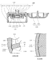
以下に、本発明の一実施形態に係る吐出キャップ100について、図面に基づいて説明する。なお、吐出キャップ100に嵌合する容器200は、容器口部201周辺のみを図示する。
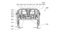
吐出キャップ100は、容器200の容器口部201に嵌合され、容器200の内部に収容された内容物Pを、容器200を吐出方向へ傾斜させて吐出するものであり、図1乃至図3に示すように、キャップ本体110と、上蓋120と、弁室130とが設けられている。
Hereinafter, the
The
キャップ本体110は、本体天面111と、本体天面111から下方に垂下する嵌合壁部112と、吐出口113a及び吐出誘導部113bを有し、本体天面111との接続部である吐出口接続部113cから突出形成された吐出筒113と、嵌合壁部112より内側で本体天面111から下方に円筒状に垂下する係合壁部114と、本体天面111の周縁部から下方に垂下するスカート壁115とを有している。
嵌合壁部112及びスカート壁115が容器口部201との嵌合部であり、キャップ本体110と容器200とは、嵌合壁部112とスカート壁115の内周面上方に設けられた係合凸部117との間に容器口部201を挿入することで嵌合し、スカート壁115の内周面下方に設けられた係止リブ116を、容器口部201の係止突条202が乗り越えた位置で吐出キャップ100と容器200との位置関係が固定される。
また、係合壁部114の下端部には内方に突出する突条114aが形成され、係合壁部114の内周面の、吐出時に傾斜した際の吐出方向側には、下方に開放した0.05mm程度の浅い溝部114bが3箇所設けられている。
The cap
The
Further, a
上蓋120は、キャップ本体110の、吐出方向とは反対側にヒンジ接続されており、上蓋天面121と、上蓋天面121から垂下した閉塞栓122とを有している。
The
中栓131は、中央に容器200の内部と連通する供給孔135を有する円環状の底部133と、底部133の外縁部から上方に延出する複数の係合柱部136と、底部133の内縁部から下方に延出する円環状の筒部137とを有している。
底部133上面から筒部137内面との弧状接続領域には後述する弁部138の弁シール面138aと当接する弁座134が形成されている。
The
A
逆止弁132は、エラストマーまたは低密度ポリエチレンの如き比較的軟質である合成樹脂から形成され、略円板形状であって下方に位置する弁部138と、円環形状であって上方に位置する基部140と、弁部138と基部140とを接続する接続片141とを有する。
弁部138の上面は上方に膨出しており、上面と下面が上方にやや膨らんだ弧状断面形状を有している。
また、弁部138の外周面下端部には半径方向内方に向かって下方に傾斜する逆円錐台形状の弁シール面138aが形成されている。
接続片141は周方向に等角度間隔を置いて3個配設される帯状部材であり、接続片141の弾性力による下向きの復元力が弁部138に常時作用する。
The
The upper surface of the
Further, an inverted truncated cone-shaped
The connecting
弁室130は、本体天面111の下面側に設けられており、本体天面111と、係合壁部114と、中栓131とで区画された空間として形成される。
弁室130内には、下方に付勢された逆止弁132の弁部138が、底部133の供給孔135の周囲に形成された弁座134に当接するように設けられている。
また、図3に示すように、底部133は半径方向外方に向かって下方へ傾斜しており、底部133及び係合柱部136と係合壁部114とが当接することで、逆止弁132が弁室130内に係合保持されるとともに、溝部114bと底部133の外周縁部とによって、弁室130と容器200の内部とを連通する細長い回収流路142が形成される。
The
In the
Further, as shown in FIG. 3, the
容器200は、内容物Pを収容する可撓性の内部容器(図示しない)と、内部容器(図示しない)を内包する弾性を備えた外部容器(図示しない)とを有し、内部容器(図示しない)と外部容器(図示しない)との間に外気Gを吸引可能な吸入弁(図示しない)が設けられており、内容物Pの吐出に伴い減少した外部容器(図示しない)内の体積を、吸入弁(図示しない)から外気Gを吸引することで復元するものである。
The
次に、本実施形態における吐出キャップ100による、内容物Pの吐出及び弁室130内に残った内容物Pの容器200内への回収動作について、図4乃至図6を用いて説明する。なお、説明のため、容器200は静置したままの図を用いる。
まず、内容物Pの吐出手順を説明する。容器200を吐出方向である吐出筒113の吐出誘導部113b側に傾け、外側から押圧すると、容器200は変形し、加圧された内容物Pが、弁座134側に付勢されている逆止弁132の弁部138を供給孔135から押し上げ、弁部138の弁シール面138aと弁座134との間を通り、弁室130内へ流入する。
さらに容器200への押圧を続けると、内容物Pは吐出口113aを通り、吐出誘導部113bに沿って吐出キャップ100外へ吐出される。このとき、回収流路142は供給孔135に比べて十分に細いため、回収流路142を通って弁室130内へ流入する内容物Pはほぼない。
Next, the discharge of the content P and the recovery operation of the content P remaining in the
First, the discharge procedure of the content P will be described. When the
Further, when the pressing on the
次に、弁室130内の内容物Pの容器200内への回収動作を説明する。内容物Pの吐出は、容器200内の内容物Pへの加圧が解除されることで止まるとともに、逆止弁132の弁部138を押し上げる力もなくなるため、供給孔135は逆止弁132の弁部138によって閉塞される。
弁室130内の内容物Pは、逆止弁132の閉塞までの僅かな時間は、供給孔135から容器200内に戻るが、全量が戻ることはなく、閉塞後にも弁室130内に内容物Pが残留する。
Next, the operation of collecting the contents P in the
The contents P in the
しかしながら、回収流路142は常に開口しているため、逆止弁132の弁部138の開閉状態に関わらず弁室130と容器200内を連通している。また、加圧を解除された外部容器(図示しない)は弾性体で構成されており、元の形状に戻ろうとするため、容器200内は一時的に負圧状態となり、容器外の流体を容器200内へ吸引する力が発生する。
However, since the
これによって、回収流路142から弁室130内に残留した内容物Pを内部容器(図示しない)内に回収することができる。なお、同時に吸入弁(図示しない)から外部容器(図示しない)内へ外気Gを吸引するため、弁室130内に残留していた内容物Pを回収した後、回収流路142から外気Gを内部容器(図示しない)内に吸引し始める前に、外部容器(図示しない)内へ外気Gが十分に吸引されることで、外部容器(図示しない)の形状及び容器200内の圧力は元の状態に戻る。さらに、回収流路142内には表面張力により内容物Pが留まるため、内部容器(図示しない)内に外気Gが流入することはなく、内部容器(図示しない)内の内容物Pの劣化を防ぐことができる。
As a result, the content P remaining in the
外部容器(図示しない)の復元後に上蓋120を閉じると、上蓋120に設けられた閉塞栓122が吐出筒113の吐出口113a内に挿入され、弁室130は外気Gと遮断される。また、逆止弁132は供給孔135を密閉しているため、回収流路142内の内容物Pに弁室130内の外気Gが接触するのみとなり、内部容器(図示しない)内の内容物Pの劣化を抑制することができる。さらに、閉塞栓122が逆止弁132の天面を押圧するように接触しているため、供給孔135の密閉を強固にできる。
When the
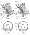
次に、容器200を吐出方向へ傾斜させながら内容物Pを吐出した際の、弁室130内における内容物Pの回収動作および外気Gの内部容器(図示しない)内への流入防止について、図7及び図8を用いて説明する。
ここで、底部133の中心から吐出時に傾斜した際の弁室130の下端に延ばした線を、底部133の周方向の時計回り及び反時計回りにそれぞれ45度ずつ回転させて形成した弧の両端を結んだ直線を、流路形成ラインLとする。
また、吐出口接続部113cのうち、吐出時に傾斜した際の最下点を、吐出時最下点Tとする。
まず、容器200を、吐出口113aの吐出方向である吐出誘導部113b側へ傾斜させ、容器200の外側から押圧すると、容器200は変形し、加圧された内容物Pが、逆止弁132を供給孔135側から押上げ、弁シール面138aと弁座134との間を通り、弁室130内へ流入する。
Next, the recovery operation of the content P in the
Here, both ends of the arc formed by rotating a line extending from the center of the bottom 133 to the lower end of the
Further, among the discharge
First, when the
このとき、弁室130内の外気Gは内容物Pの流入に伴い、吐出口113aから吐出誘導部113bに沿って容器200外へ排出されるが、容器200の吐出方向への傾斜時において、弁室130内の空間の上方に、外気Gが僅かに残ることがある。
ここで、容器200の吐出方向への傾斜時において、弁室130内の液面位置Sは、図7(a)に示すように、弁室130内の空間の、吐出口113aと弁室130との接続部である吐出口接続部113cよりも上方に位置しており、回収流路142は、図7(a′)に示すように、液面位置Sよりも下方に設けられていることから、弁室130内の外気Gは内容物Pの流動に沿って吐出口113aから吐出キャップ100外へ排出されるか、弁室130内に留まるため、内部容器内に外気Gが流入することはない。
At this time, the outside air G in the
Here, when the
次に、容器200からの内容物Pの吐出後、容器200への加圧を解除すると、内容物Pの吐出が止まり、供給孔135は逆止弁132によって弁室130との連通を解除され、内容物Pは回収流路142を介して内部容器(図示しない)内へ回収され始める。
このとき、容器200を吐出方向へ傾斜させたまま容器200への加圧を解除しても、容器200の吐出方向への傾斜時において、弁室130内の液面位置Sは、図7(b)に示すように、吐出口接続部113cよりも上方に位置しており、回収流路142は、図7(b′)に示すように、液面位置Sよりも下方に設けられていることから、弁室130内の内容物Pを回収し終えるまでは、回収流路142に外気Gが触れることがない。
Next, when the pressurization to the
At this time, even if the pressurization on the
なお、弁室130内の内容物Pを回収していくと、液面位置Sは、図8(c)に示すように、吐出時最下点Tまで下がり、徐々に回収流路142側へ近づいていくが、図8(c′)に示すように、回収流路142は液面位置Sよりも下方に位置しており、回収流路142に外気Gが触れることはなく、弁室130内の内容物Pを安定して回収することができる。
特に、図8(d)に示すように、弁室130内の内容物Pが残り僅かになった場合でも、流路形成ラインLを基準線として、弁室130の中心と対向する側に回収流路142を形成することで、図8(d′)に示すように、確実に外気Gが触れることがなく、弁室130内の内容物Pを回収することができるより好適な回収流路142を形成できる。
When the content P in the
In particular, as shown in FIG. 8D, even when the content P in the
また、弁室130内の内容物Pを回収後も、回収流路142内には表面張力により内容物Pが留まるため、内部容器(図示しない)内に外気Gが流入することはない。
これによって、内容物Pの吐出時及び回収時のどちらにおいても、弁室130内に外気Gが残っていても、内部容器(図示しない)内へ外気Gが流入することはなく、内部容器(図示しない)内の内容物Pの劣化を防ぐことが出来る。
Further, even after the content P in the
As a result, even if the outside air G remains in the
以上、本発明の実施形態を詳述したが、本発明は上記実施形態に限定されるものではなく、特許請求の範囲に記載された本発明を逸脱することなく種々の設計変更を行うことが可能である。
なお、上述した実施形態では、容器は内容物を収容する可撓性の内部容器と、内部容器を内包する弾性を備えた外部容器とで構成されているものとして説明したが、容器の構成はこれに限定されず、例えば、内部容器を用いずに外部容器のみで構成してもよく、容器底部に上下動可能なピストンを設けて、容器内容積が可変となるように構成してもよい。
また、上述した実施形態では、吐出キャップにはヒンジ接続された上蓋が設けられているものとして説明したが、吐出キャップの形態はこれに限定されず、例えば、上蓋がなくてもよく、キャップ本体とは別体のスクリューキャップ式の上蓋として設けてもよい。
また、上述した実施形態では、上蓋は、キャップ本体の、吐出方向とは反対側にヒンジ接続されているものとして説明したが、上蓋とキャップ本体との接続状態はこれに限定されず、例えば、キャップ本体の、吐出方向と90度向きを変えた位置に接続されていてもよい。
Although the embodiments of the present invention have been described in detail above, the present invention is not limited to the above embodiments, and various design changes can be made without departing from the present invention described in the claims. It is possible.
In the above-described embodiment, the container has been described as being composed of a flexible inner container for accommodating the contents and an elastic outer container containing the inner container. The present invention is not limited to this, and for example, it may be configured only by an outer container without using an inner container, or a piston that can move up and down may be provided at the bottom of the container so that the internal volume of the container can be changed. ..
Further, in the above-described embodiment, it has been described that the discharge cap is provided with a hinged upper lid, but the form of the discharge cap is not limited to this, and for example, the cap body may not have an upper lid. It may be provided as a screw cap type upper lid separate from the above.
Further, in the above-described embodiment, the upper lid is described as being hinged to the side opposite to the discharge direction of the cap body, but the connection state between the upper lid and the cap body is not limited to this, for example. It may be connected to a position on the cap body that is 90 degrees different from the discharge direction.
また、上述した実施形態では、係合壁の内周面には、下方に開放した浅い溝部が設けられており、係合壁部と底部とが当接することで回収流路が形成されているものとして説明したが、回収流路の形成方法はこれに限定されず、例えば、溝部の代わりに粗面加工を設けたり、底部の外周縁部に下方に開放したスリットを設けてもよく、係合壁部や底部に、弁室と容器とを連通する小孔を設けてもよい。
また、係合壁部の内周面に回収流路が形成されているものを説明したが、回収流路の位置はこれに限定されず、例えば、底部の外周縁部に回収流路を設けてもよい。
Further, in the above-described embodiment, a shallow groove portion opened downward is provided on the inner peripheral surface of the engaging wall, and a recovery flow path is formed by the contact between the engaging wall portion and the bottom portion. However, the method of forming the recovery flow path is not limited to this, and for example, rough surface processing may be provided instead of the groove portion, or a slit open downward may be provided at the outer peripheral edge portion of the bottom portion. A small hole for communicating the valve chamber and the container may be provided in the abutment wall or the bottom.
Further, although the recovery flow path is formed on the inner peripheral surface of the engaging wall portion, the position of the recovery flow path is not limited to this, and for example, the recovery flow path is provided on the outer peripheral edge portion of the bottom portion. You may.
また、上述した実施形態では、弁室は、本体天面と、係合壁部と、中栓とで区画された空間として形成されているものとして説明したが、弁室の形成方法はこれに限定されず、例えば、キャップ本体とは別体の弁室を用意し、キャップ本体の所定の位置に弁室を嵌合させて吐出キャップを構成するようにしてもよく、容器口部の先端に中栓を設け、キャップ本体と容器口部を嵌合することで弁室を形成してもよい。
また、上述した実施形態では、係合壁部の内周面の、吐出時に傾斜した際の吐出方向側には、下方に開放した0.05mm程度の浅い溝部が3箇所設けられ、溝部と底部の外周縁部とによって、弁室と容器の内部とを連通する細長い回収流路が形成されているものとして説明したが、溝部の数やサイズはこれに限定されず、例えば、溝部が1つでもよく、0.1mm程度の浅い溝部でもよい。
Further, in the above-described embodiment, the valve chamber has been described as being formed as a space partitioned by the top surface of the main body, the engaging wall portion, and the inner plug, but the method of forming the valve chamber is based on this. Not limited to this, for example, a valve chamber separate from the cap body may be prepared, and the valve chamber may be fitted at a predetermined position on the cap body to form a discharge cap. A valve chamber may be formed by providing an inner plug and fitting the cap body and the container mouth portion.
Further, in the above-described embodiment, three shallow groove portions of about 0.05 mm opened downward are provided on the discharge direction side of the inner peripheral surface of the engaging wall portion when tilted at the time of discharge, and the groove portion and the bottom portion are provided. Although it has been described that an elongated recovery flow path connecting the valve chamber and the inside of the container is formed by the outer peripheral edge portion of the above, the number and size of the groove portions are not limited to this, for example, one groove portion. However, a shallow groove portion of about 0.1 mm may be used.
100 ・・・ 吐出キャップ
110 ・・・ キャップ本体
111 ・・・ 本体天面
112 ・・・ 嵌合壁部
113 ・・・ 吐出筒
113a ・・・ 吐出口
113b ・・・ 吐出誘導部
113c ・・・ 吐出口接続部
114 ・・・ 係合壁部
114a ・・・ 突条
114b ・・・ 溝部
115 ・・・ スカート壁
116 ・・・ 係止リブ
117 ・・・ 係合凸部
120 ・・・ 上蓋
121 ・・・ 上蓋天面
122 ・・・ 閉塞栓
130 ・・・ 弁室
131 ・・・ 中栓
132 ・・・ 逆止弁
133 ・・・ 底部
134 ・・・ 弁座
135 ・・・ 供給孔
136 ・・・ 係合柱部
137 ・・・ 筒部
138 ・・・ 弁部
138a ・・・ 弁シール面
140 ・・・ 基部
141 ・・・ 接続片
142 ・・・ 回収流路
200 ・・・ 容器
201 ・・・ 容器口部
202 ・・・ 係止突条
P ・・・ 内容物
G ・・・ 外気
S ・・・ 液面位置
L ・・・ 流路形成ライン
T ・・・ 吐出時最下点
100 ・ ・ ・
Claims (11)
前記吐出キャップは、容器口部と嵌合する嵌合部と、容器内部に収容された内容物を吐出する吐出口とを有するとともに、容器内部と前記吐出口との間に区画された弁室をさらに有し、
前記弁室には、容器内部と連通し、内容物を取り出す供給孔及び弁座を有する底部と、逆止弁と、前記弁室と容器内部とを連通する少なくとも1つの回収流路とが設けられ、
前記逆止弁は前記供給孔の軸線方向に沿って摺動可能に設けられるとともに、前記弁座方向に付勢されて前記弁座と当接可能に構成され、
前記回収流路は、少なくとも前記弁座よりも外周側で、かつ、吐出時に傾斜した際の前記弁室内の内容物の液面よりも下方の位置にのみ設けられ、
前記吐出キャップには、前記吐出口を閉塞する閉塞栓を有した上蓋が設けられ、
前記閉塞栓は、前記上蓋を閉じた際に、前記逆止弁を押圧することを特徴とする吐出キャップ。 A discharge cap that is fitted to the mouth of the container and that tilts and discharges the contents contained inside the container.
The discharge cap has a fitting portion that fits with the container port portion and a discharge port that discharges the contents contained in the container, and a valve chamber partitioned between the inside of the container and the discharge port. Have more
The valve chamber is provided with a bottom having a supply hole and a valve seat that communicate with the inside of the container and take out the contents, a check valve, and at least one recovery flow path that communicates between the valve chamber and the inside of the container. Be,
The check valve is slidably provided along the axial direction of the supply hole, and is urged in the valve seat direction so as to be in contact with the valve seat.
The recovery flow path is provided at least on the outer peripheral side of the valve seat and at a position below the liquid level of the contents in the valve chamber when tilted at the time of discharge .
The discharge cap is provided with an upper lid having a blocking plug for closing the discharge port.
The obstruction plug is a discharge cap that presses the check valve when the upper lid is closed.
前記キャップ本体には、前記キャップ本体の本体天面から上方に突出した吐出口と、前記本体天面の下面から円筒状に垂下した係合壁部とが設けられ、 The cap body is provided with a discharge port protruding upward from the top surface of the cap body and an engaging wall portion that hangs cylindrically from the lower surface of the top surface of the main body.
前記中栓には、前記供給孔及び前記弁座を有した前記底部が設けられ、 The inner plug is provided with the supply hole and the bottom portion having the valve seat.
前記弁室は、前記係合壁部に前記中栓が嵌合することで形成され、 The valve chamber is formed by fitting the inner plug to the engaging wall portion.
前記中栓と前記係合壁部との間には、前記回収流路が設けられていることを特徴とする請求項1に記載の吐出キャップ。 The discharge cap according to claim 1, wherein a recovery flow path is provided between the inner plug and the engaging wall portion.
前記吐出キャップは、キャップ本体と中栓とを有し、 The discharge cap has a cap body and an inner plug, and has a cap body and an inner plug.
前記吐出キャップは、容器口部と嵌合する嵌合部と、容器内部に収容された内容物を吐出する吐出口とを有するとともに、容器内部と前記吐出口との間に区画された弁室をさらに有し、 The discharge cap has a fitting portion that fits with the container port portion and a discharge port that discharges the contents contained in the container, and a valve chamber partitioned between the inside of the container and the discharge port. Have more
前記弁室には、容器内部と連通し、内容物を取り出す供給孔及び弁座を有する底部と、逆止弁と、前記弁室と容器内部とを連通する少なくとも1つの回収流路とが設けられ、 The valve chamber is provided with a bottom having a supply hole and a valve seat that communicate with the inside of the container and take out the contents, a check valve, and at least one recovery flow path that communicates between the valve chamber and the inside of the container. Be,
前記逆止弁は前記供給孔の軸線方向に沿って摺動可能に設けられるとともに、前記弁座方向に付勢されて前記弁座と当接可能に構成され、 The check valve is slidably provided along the axial direction of the supply hole, and is urged in the valve seat direction so as to be in contact with the valve seat.
前記回収流路は、少なくとも前記弁座よりも外周側で、かつ、吐出時に傾斜した際の前記弁室内の内容物の液面よりも下方の位置にのみ設けられ、 The recovery flow path is provided at least on the outer peripheral side of the valve seat and at a position below the liquid level of the contents in the valve chamber when tilted at the time of discharge.
前記キャップ本体には、前記キャップ本体の本体天面から上方に突出した前記吐出口と、前記本体天面の下面から円筒状に垂下した係合壁部とが設けられ、 The cap body is provided with the discharge port protruding upward from the top surface of the main body of the cap body and an engaging wall portion cylindrically hung from the lower surface of the top surface of the main body.
前記中栓には、前記供給孔および前記弁座を有した前記底部が設けられ、 The inner plug is provided with the supply hole and the bottom portion having the valve seat.
前記弁室は、前記係合壁部に前記中栓が嵌合することで形成され、 The valve chamber is formed by fitting the inner plug to the engaging wall portion.
前記中栓と前記係合壁部の間には、前記回収流路が設けられていることを特徴とする吐出キャップ。 A discharge cap characterized in that a recovery flow path is provided between the inner plug and the engaging wall portion.
前記閉塞栓は、前記上蓋を閉じた際に、前記逆止弁を押圧することを特徴とする請求項3に記載の吐出キャップ。 The discharge cap according to claim 3, wherein the block plug presses the check valve when the upper lid is closed.
前記上蓋は、吐出時に傾斜した際の前記キャップ本体の上端側にヒンジによって接続されていることを特徴とする請求項7に記載の吐出キャップ。 The discharge cap is provided with a cap body having the fitting portion, the discharge port, and the valve chamber.
The discharge cap according to claim 7 , wherein the upper lid is connected to the upper end side of the cap body when it is tilted at the time of discharge by a hinge.
前記容器は、内容物を収容する可撓性の内部容器と、前記内部容器を内包する外部容器とを有し、
前記外部容器には、前記内部容器と前記外部容器との間に外気を吸引可能な吸入弁が設けられていることを特徴とする容器。 A container that fits into the discharge cap according to any one of claims 1 to 10.
The container has a flexible inner container for accommodating the contents and an outer container containing the inner container.
The outer container is provided with a suction valve capable of sucking outside air between the inner container and the outer container.
Priority Applications (1)
| Application Number | Priority Date | Filing Date | Title |
|---|---|---|---|
| JP2017051534A JP6888991B2 (en) | 2017-03-16 | 2017-03-16 | Discharge cap |
Applications Claiming Priority (1)
| Application Number | Priority Date | Filing Date | Title |
|---|---|---|---|
| JP2017051534A JP6888991B2 (en) | 2017-03-16 | 2017-03-16 | Discharge cap |
Publications (3)
| Publication Number | Publication Date |
|---|---|
| JP2018154356A JP2018154356A (en) | 2018-10-04 |
| JP2018154356A5 JP2018154356A5 (en) | 2019-03-07 |
| JP6888991B2 true JP6888991B2 (en) | 2021-06-18 |
Family
ID=63716193
Family Applications (1)
| Application Number | Title | Priority Date | Filing Date |
|---|---|---|---|
| JP2017051534A Active JP6888991B2 (en) | 2017-03-16 | 2017-03-16 | Discharge cap |
Country Status (1)
| Country | Link |
|---|---|
| JP (1) | JP6888991B2 (en) |
Families Citing this family (3)
| Publication number | Priority date | Publication date | Assignee | Title |
|---|---|---|---|---|
| JP6899582B2 (en) * | 2017-08-03 | 2021-07-07 | 東京ライト工業株式会社 | cap |
| KR102206401B1 (en) * | 2019-05-02 | 2021-01-22 | 주식회사 블리스팩 | The blister package with shoulder part integral flip top cap |
| WO2023048141A1 (en) * | 2021-09-22 | 2023-03-30 | 東京ライト工業株式会社 | Cap |
Family Cites Families (4)
| Publication number | Priority date | Publication date | Assignee | Title |
|---|---|---|---|---|
| US20130026196A1 (en) * | 2011-07-25 | 2013-01-31 | Jan Essebaggers | Self closing flow control device with adjustable actuator element for container closures |
| JP2013241197A (en) * | 2012-05-21 | 2013-12-05 | Daiwa Can Co Ltd | Cap |
| JP5963323B2 (en) * | 2014-08-05 | 2016-08-03 | 東京ライト工業株式会社 | cap |
| KR102067509B1 (en) * | 2016-05-20 | 2020-01-17 | 도쿄 라이트 고교 가부시키가이샤 | Cap and discharge vessel |
-
2017
- 2017-03-16 JP JP2017051534A patent/JP6888991B2/en active Active
Also Published As
| Publication number | Publication date |
|---|---|
| JP2018154356A (en) | 2018-10-04 |
Similar Documents
| Publication | Publication Date | Title |
|---|---|---|
| JP6776044B2 (en) | Discharge cap | |
| JP6710462B2 (en) | Discharge container | |
| JP6888991B2 (en) | Discharge cap | |
| KR102067509B1 (en) | Cap and discharge vessel | |
| JP5961452B2 (en) | Discharge container | |
| KR200449631Y1 (en) | Hand-operated Dropper | |
| JP2013014341A (en) | Discharging container | |
| JP2017081628A (en) | Discharge container | |
| JP5883626B2 (en) | Discharge container | |
| KR101627227B1 (en) | The Sealing structure of cream type cosmetic case | |
| JP6809883B2 (en) | Discharge cap | |
| JP6710468B2 (en) | Discharge container | |
| JP2020193026A (en) | Dispensing cap for double container and double container | |
| JP2016141428A (en) | Squeeze foamer container | |
| JP6971186B2 (en) | Discharge container | |
| JP5871731B2 (en) | Discharge container | |
| JP2007302253A (en) | Discharging container | |
| JP7074522B2 (en) | Discharge cap | |
| JP2020121751A (en) | Discharge cap | |
| JP2022171033A (en) | discharge cap | |
| JP7174556B2 (en) | discharge cap | |
| JP2018095287A (en) | Synthetic resin container lid | |
| JP7519809B2 (en) | Discharge Cap | |
| JP4666490B2 (en) | Liquid ejector | |
| JP7072987B2 (en) | Discharge container |
Legal Events
| Date | Code | Title | Description |
|---|---|---|---|
| A521 | Written amendment |
Free format text: JAPANESE INTERMEDIATE CODE: A523 Effective date: 20190123 |
|
| A625 | Written request for application examination (by other person) |
Free format text: JAPANESE INTERMEDIATE CODE: A625 Effective date: 20200214 |
|
| RD04 | Notification of resignation of power of attorney |
Free format text: JAPANESE INTERMEDIATE CODE: A7424 Effective date: 20200716 |
|
| A977 | Report on retrieval |
Free format text: JAPANESE INTERMEDIATE CODE: A971007 Effective date: 20201216 |
|
| A131 | Notification of reasons for refusal |
Free format text: JAPANESE INTERMEDIATE CODE: A131 Effective date: 20210105 |
|
| A521 | Written amendment |
Free format text: JAPANESE INTERMEDIATE CODE: A523 Effective date: 20210305 |
|
| TRDD | Decision of grant or rejection written | ||
| A01 | Written decision to grant a patent or to grant a registration (utility model) |
Free format text: JAPANESE INTERMEDIATE CODE: A01 Effective date: 20210518 |
|
| A61 | First payment of annual fees (during grant procedure) |
Free format text: JAPANESE INTERMEDIATE CODE: A61 Effective date: 20210520 |
|
| R150 | Certificate of patent or registration of utility model |
Ref document number: 6888991 Country of ref document: JP Free format text: JAPANESE INTERMEDIATE CODE: R150 |