JP6885023B2 - Image processing device and image processing method - Google Patents
Image processing device and image processing method Download PDFInfo
- Publication number
- JP6885023B2 JP6885023B2 JP2016222950A JP2016222950A JP6885023B2 JP 6885023 B2 JP6885023 B2 JP 6885023B2 JP 2016222950 A JP2016222950 A JP 2016222950A JP 2016222950 A JP2016222950 A JP 2016222950A JP 6885023 B2 JP6885023 B2 JP 6885023B2
- Authority
- JP
- Japan
- Prior art keywords
- dot
- data
- nozzle row
- corrected
- trailing
- Prior art date
- Legal status (The legal status is an assumption and is not a legal conclusion. Google has not performed a legal analysis and makes no representation as to the accuracy of the status listed.)
- Active
Links
Images


Classifications
-
- B—PERFORMING OPERATIONS; TRANSPORTING
- B41—PRINTING; LINING MACHINES; TYPEWRITERS; STAMPS
- B41J—TYPEWRITERS; SELECTIVE PRINTING MECHANISMS, i.e. MECHANISMS PRINTING OTHERWISE THAN FROM A FORME; CORRECTION OF TYPOGRAPHICAL ERRORS
- B41J2/00—Typewriters or selective printing mechanisms characterised by the printing or marking process for which they are designed
- B41J2/005—Typewriters or selective printing mechanisms characterised by the printing or marking process for which they are designed characterised by bringing liquid or particles selectively into contact with a printing material
- B41J2/01—Ink jet
- B41J2/015—Ink jet characterised by the jet generation process
- B41J2/04—Ink jet characterised by the jet generation process generating single droplets or particles on demand
- B41J2/045—Ink jet characterised by the jet generation process generating single droplets or particles on demand by pressure, e.g. electromechanical transducers
- B41J2/04501—Control methods or devices therefor, e.g. driver circuits, control circuits
- B41J2/04593—Dot-size modulation by changing the size of the drop
-
- B—PERFORMING OPERATIONS; TRANSPORTING
- B41—PRINTING; LINING MACHINES; TYPEWRITERS; STAMPS
- B41J—TYPEWRITERS; SELECTIVE PRINTING MECHANISMS, i.e. MECHANISMS PRINTING OTHERWISE THAN FROM A FORME; CORRECTION OF TYPOGRAPHICAL ERRORS
- B41J2/00—Typewriters or selective printing mechanisms characterised by the printing or marking process for which they are designed
- B41J2/005—Typewriters or selective printing mechanisms characterised by the printing or marking process for which they are designed characterised by bringing liquid or particles selectively into contact with a printing material
- B41J2/01—Ink jet
- B41J2/21—Ink jet for multi-colour printing
- B41J2/2121—Ink jet for multi-colour printing characterised by dot size, e.g. combinations of printed dots of different diameter
- B41J2/2128—Ink jet for multi-colour printing characterised by dot size, e.g. combinations of printed dots of different diameter by means of energy modulation
-
- B—PERFORMING OPERATIONS; TRANSPORTING
- B41—PRINTING; LINING MACHINES; TYPEWRITERS; STAMPS
- B41J—TYPEWRITERS; SELECTIVE PRINTING MECHANISMS, i.e. MECHANISMS PRINTING OTHERWISE THAN FROM A FORME; CORRECTION OF TYPOGRAPHICAL ERRORS
- B41J19/00—Character- or line-spacing mechanisms
- B41J19/14—Character- or line-spacing mechanisms with means for effecting line or character spacing in either direction
- B41J19/142—Character- or line-spacing mechanisms with means for effecting line or character spacing in either direction with a reciprocating print head printing in both directions across the paper width
- B41J19/145—Dot misalignment correction
-
- B—PERFORMING OPERATIONS; TRANSPORTING
- B41—PRINTING; LINING MACHINES; TYPEWRITERS; STAMPS
- B41J—TYPEWRITERS; SELECTIVE PRINTING MECHANISMS, i.e. MECHANISMS PRINTING OTHERWISE THAN FROM A FORME; CORRECTION OF TYPOGRAPHICAL ERRORS
- B41J2/00—Typewriters or selective printing mechanisms characterised by the printing or marking process for which they are designed
- B41J2/005—Typewriters or selective printing mechanisms characterised by the printing or marking process for which they are designed characterised by bringing liquid or particles selectively into contact with a printing material
- B41J2/01—Ink jet
- B41J2/015—Ink jet characterised by the jet generation process
- B41J2/04—Ink jet characterised by the jet generation process generating single droplets or particles on demand
- B41J2/045—Ink jet characterised by the jet generation process generating single droplets or particles on demand by pressure, e.g. electromechanical transducers
- B41J2/04501—Control methods or devices therefor, e.g. driver circuits, control circuits
- B41J2/04586—Control methods or devices therefor, e.g. driver circuits, control circuits controlling heads of a type not covered by groups B41J2/04575 - B41J2/04585, or of an undefined type
Description
本発明は、画像処理装置および画像処理方法に関し、特に、インク滴などの液滴を吐出して印刷を行う印刷装置用の印刷データを画像データから生成する画像処理装置および画像処理方法に関する。 The present invention relates to an image processing apparatus and an image processing method, and more particularly to an image processing apparatus and an image processing method that generate print data from image data for a printing apparatus that ejects droplets such as ink droplets for printing.
インクジェットプリンターでは、キャリッジ移動に伴い主走査方向の先行側にある空気は、相対的にキャリッジの後方に移動する。このうちペーパーギャップを通る空気によりドットが副走査方向に延びて着弾するが、この延び量は主走査方向先行側の列ほど大きくなる。
特許文献1記載の技術では、キャリッジの移動方向の前方に向かう気流を発生させる可動部材(ベルトやローラ)を設けている。これにより、キャリッジの移動速度に依存することなく、吐出口と記録媒体の間へ流入する気流を阻止する。すると、風紋を低減することが可能となるとしている。
In an inkjet printer, the air on the leading side in the main scanning direction moves relatively to the rear of the carriage as the carriage moves. Of these, the dots extend in the sub-scanning direction and land due to the air passing through the paper gap, and the amount of extension increases as the row on the leading side in the main scanning direction increases.
In the technique described in Patent Document 1, a movable member (belt or roller) for generating an air flow toward the front in the moving direction of the carriage is provided. As a result, the airflow flowing between the discharge port and the recording medium is blocked regardless of the moving speed of the carriage. Then, it is possible to reduce the wind pattern.
上述した従来の技術によれば、ベルトやローラといった可動部材を印刷装置に別途設ける必要がある。すると、印刷装置の構造が複雑になるという問題や、印刷装置の製造コストが増加するという問題があり風紋に対して改善の余地があった。
本発明は、風紋を低減する画像処理装置および画像処理方法を提供する。
According to the above-mentioned conventional technique, it is necessary to separately provide a movable member such as a belt or a roller in the printing apparatus. Then, there is a problem that the structure of the printing apparatus becomes complicated and a problem that the manufacturing cost of the printing apparatus increases, and there is room for improvement in the wind pattern.
The present invention provides an image processing apparatus and an image processing method for reducing wind patterns.
本発明は、媒体に対して相対的に主走査方向へ移動可能であり、同色のインクを吐出してドットを形成するためのノズルが前記主走査方向に複数設けられたヘッドを備える印刷装置用の印刷データを、画像データから生成する画像処理装置であって、前記画像データから、ドットデータを生成するハーフトーン処理部と、前記ドットデータに基づいて前記印刷データを生成する印刷データ生成部とを備え、第1ドットおよび前記第1ドットより大きい第2ドットを含むドットサイズおよびドット位置を有するドットデータを生成する際に、第1ドットおよび第2ドットが前記主走査方向における先行ノズル列および後行ノズル列のどちらに該当するかに応じて、第1ドットおよび第2ドットのドットデータを補正する構成としてある。 The present invention is for a printing apparatus including a head that is movable in the main scanning direction relative to the medium and has a plurality of nozzles for ejecting ink of the same color to form dots in the main scanning direction. An image processing device that generates print data from the image data, a halftone processing unit that generates dot data from the image data, and a print data generation unit that generates the print data based on the dot data. When generating dot data having a dot size and a dot position including a first dot and a second dot larger than the first dot, the first dot and the second dot are the preceding nozzle array in the main scanning direction and It is configured to correct the dot data of the first dot and the second dot according to which of the trailing nozzle rows corresponds to.
前記構成において、ハーフトーン処理部と印刷データ生成部とにより、第1ドットおよび前記第1ドットより大きい第2ドットを含むドットサイズおよびドット位置を有するドットデータを生成する際に、第1ドットおよび第2ドットが前記主走査方向における先行ノズル列および後行ノズル列のどちらに該当するかを判定し、判定の結果に応じて第1ドットおよび第2ドットのドットデータを補正する。 In the above configuration, when the halftone processing unit and the print data generation unit generate dot data having a dot size and a dot position including a first dot and a second dot larger than the first dot, the first dot and the print data generation unit It is determined whether the second dot corresponds to the leading nozzle row or the trailing nozzle row in the main scanning direction, and the dot data of the first dot and the second dot is corrected according to the result of the determination.
一例として、第1ドットを小ドットと呼び、これより大きな第2ドットを大ドットと呼ぶとすると、第1ドットが先行ノズル列にあれば、後行ノズル列に移動するように補正したり、第2ドットが後行ノズル列にあれば、先行ノズル列に移動するように補正したりすることが可能である。
本発明の他の態様として、前記ハーフトーン処理部は、前記画像データから第1ドットおよび前記第1ドットより大きい第2ドットを含むドットサイズおよびドット位置を有するドットデータを生成し、前記印刷データ生成部は、第1ドットおよび第2ドットが前記主走査方向における先行ノズル列および後行ノズル列のどちらに該当するかに応じて、第1ドットおよび第2のドットのデータを補正して補正データを生成し、当該補正データに基づいて前記印刷データを生成する構成としてある。
As an example, if the first dot is called a small dot and the second dot larger than this is called a large dot, if the first dot is in the leading nozzle row, it may be corrected to move to the trailing nozzle row. If the second dot is in the trailing nozzle row, it can be corrected to move to the leading nozzle row.
As another aspect of the present invention, the halftone processing unit generates dot data having a dot size and a dot position including a first dot and a second dot larger than the first dot from the image data, and the print data. The generation unit corrects and corrects the data of the first dot and the second dot according to whether the first dot and the second dot correspond to the leading nozzle row or the trailing nozzle row in the main scanning direction. The configuration is such that data is generated and the print data is generated based on the correction data.
前記画像データから第1ドットおよび前記第1ドットより大きい第2ドットを含むドットサイズおよびドット位置を有するドットデータを生成する処理が通常のハーフトーン処理である。前記構成においては、この通常のハーフトーン処理を、ハーフトーン処理部が行なう。このため、前記印刷データ生成部が、第1ドットおよび第2ドットが前記主走査方向における先行ノズル列および後行ノズル列のどちらに該当するかに応じて、第1ドットおよび第2のドットのデータを補正して補正データを生成し、当該補正データに基づいて前記印刷データを生成する。 A normal halftone process is a process of generating dot data having a dot size and a dot position including a first dot and a second dot larger than the first dot from the image data. In the above configuration, the halftone processing unit performs this normal halftone processing. Therefore, the print data generation unit determines that the first dot and the second dot of the first dot and the second dot correspond to either the preceding nozzle row or the trailing nozzle row in the main scanning direction. The data is corrected to generate correction data, and the print data is generated based on the correction data.
本発明の他の態様として、前記ハーフトーン処理部は、前記画像データから、第1ドットおよび前記第1ドットより大きい第2ドットを含むドットサイズおよびドット位置を有するドットデータを生成する際に、第1ドットおよび第2ドットが前記主走査方向における先行ノズル列および後行ノズル列のどちらに該当するかに応じて、第1ドットおよび第2ドットのドットデータを補正してドットデータを生成する構成としてある。 As another aspect of the present invention, the halftone processing unit generates dot data having a dot size and a dot position including a first dot and a second dot larger than the first dot from the image data. Dot data is generated by correcting the dot data of the first dot and the second dot according to whether the first dot and the second dot correspond to the leading nozzle row or the trailing nozzle row in the main scanning direction. It is a configuration.
前記構成において、前記ハーフトーン処理部が、通常のハーフトーン処理に加えて、第1ドットおよび第2ドットが前記主走査方向における先行ノズル列および後行ノズル列のどちらに該当するかに応じて、第1ドットおよび第2ドットのドットデータを補正してドットデータを生成する。 In the configuration, in addition to the normal halftone processing, the halftone processing unit determines whether the first dot and the second dot correspond to the leading nozzle row or the trailing nozzle row in the main scanning direction. , The dot data of the first dot and the second dot is corrected to generate the dot data.
本発明の画像処理装置および画像処理方法によれば、風紋を低減することができる。 According to the image processing apparatus and the image processing method of the present invention, wind patterns can be reduced.
(第1実施形態)
以下、図面にもとづいて本発明の実施形態を説明する。
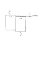
図1は、本発明が適用される印刷システムのブロック図である。
同図において、プリンター(印刷装置)10の印刷ヘッド17はインクタンクから供給される4色あるいは6色の色インクをノズルから吐出する。用紙の送り方向にノズルが配向された印刷ヘッド17は、キャリッジモーター18にて駆動されるベルト19によって所定の範囲を往復駆動される。このように印刷ヘッド17が用紙の搬送に合わせて往復動するタイプのプリンターは、各種の呼び方があるものの、ここではシリアルプリンターと呼ぶ。
(First Embodiment)
Hereinafter, embodiments of the present invention will be described with reference to the drawings.
FIG. 1 is a block diagram of a printing system to which the present invention is applied.
In the figure, the print head 17 of the printer (printing apparatus) 10 ejects four or six color inks supplied from the ink tank from a nozzle. The print head 17 whose nozzles are oriented in the paper feeding direction is reciprocated within a predetermined range by a
印刷ヘッド17は、プラテン12がプラテンモーター13によって回転駆動されることで用紙が印刷ヘッド17と交差して搬送される。印刷ヘッド17は、用紙の搬送方向に沿ってノズルが配列されており、用紙の搬送と、用紙の幅方向への印刷ヘッド17の往復動により、用紙上を相対的に移動する。用紙の幅方向への印刷ヘッド17の往復動を主走査方向と呼び、用紙が送られて相対的に印刷ヘッド17が用紙上を用紙長さ方向に移動する方向を副走査方向と呼ぶ。
フィードモーター14は所定の用紙スタッカに収容されている用紙を供給する給紙ロー
In the print head 17, the
The
ラー15を駆動する。
なお、印刷ヘッドが用紙の幅方向にわたって配置されて静止し、用紙の搬送に合わせて相対的に移動するタイプのプリンターをラインプリンターと呼ぶ。
制御回路20は、専用のICを組み合わせて構成され、機能的にはCPU、ROM、RAMを備えている。制御回路20は、印刷ヘッド17、キャリッジモーター18、プラテンモーター13、フィードモーター14の駆動を制御する。制御回路20には、操作パネル・表示部16が装着されており、操作パネル・表示部16にてユーザによる所定の操作を受け付け、また、所定の表示を行わせる。前記ハードウェアを総称して印刷機構と呼ぶ。
Drive the Ra 15.
A type of printer in which the print heads are arranged along the width direction of the paper, stand still, and move relatively in accordance with the transport of the paper is called a line printer.
The
制御回路20は、印刷ヘッド17でインク滴を吐出させる駆動信号を出力するものとし、小ドット、中ドット、大ドットという異なるサイズの複数のインク滴を吐出させる。このようなマルチサイズドットの吐出の手法はいくつか実現されているが、例えば、小ドットや中ドットを2度吐出して大ドットとさせるものも含む。一方、小ドット、中ドット、大ドットは、インク量を意味する印刷データに基づいて選択されている。
本プリンター10は、ネットワーク30に接続され、当該ネットワーク30を介してPC40などから印刷データを取得すると、同印刷データに対応した印刷を実行する。
The
When the
図2は、印刷ヘッドの構造を示している。
本実施例の印刷ヘッド17は、第1のヘッド17−1と、第2のヘッド17−2とから構成されている。それぞれの第1のヘッド17−1、第2のヘッド17−2は、300NPIのノズル密度であり、両者を主走査方向に重なるように接続してある。このとき、ノズルピッチの半分だけ副走査方向にずらしてある。これにより、両者のノズルは、互いに他方のノズルの間の位置することになるから、二つのヘッド17−1,17−2により、印刷ヘッド17は単体の300NPIのノズルピッチから2倍の精度の600NPIのノズルピッチとなっている。
FIG. 2 shows the structure of the print head.
The print head 17 of this embodiment is composed of a first head 17-1 and a second head 17-2. The first head 17-1 and the second head 17-2 have a nozzle density of 300 NPI, and they are connected so as to overlap each other in the main scanning direction. At this time, the nozzle pitch is shifted by half in the sub-scanning direction. As a result, both nozzles are located between the other nozzles, so that the two heads 17-1 and 17-2 make the print head 17 twice as accurate as the nozzle pitch of a single 300 NPI. The nozzle pitch is 600 NPI.
図3は、印刷ヘッドのノズルとインク色の配置を示している。
同図に示すように、各ヘッド17−1,17−2は、それぞれシアン、イエロー、マゼンタ、ブラックの4色が供給されるノズル列を備えている。右列からA列、B列、C列、D列、E列、F列、G列、H列と呼ぶ。また、インク色は、A列からシアン、イエロー、マゼンタ、ブラック、ブラック、マゼンタ、イエロー、シアンの順となっている。すなわち、各ヘッド17−1,17−2の接続部を境として反対の順になっている。このため、シアンを吐出するノズル列同士が最も間隔が大きく、ブラックを吐出するノズル列同士が最も間隔が小さい。
FIG. 3 shows the arrangement of the nozzles and ink colors of the print head.
As shown in the figure, each of the heads 17-1 and 17-2 has a nozzle row to which four colors of cyan, yellow, magenta, and black are supplied. From the right column, they are called A column, B column, C column, D column, E column, F column, G column, and H column. The ink colors are in the order of cyan, yellow, magenta, black, black, magenta, yellow, and cyan from column A. That is, the order is opposite with the connection portion of each head 17-1 and 17-2 as a boundary. Therefore, the distance between the nozzle rows that discharge cyan is the largest, and the distance between the nozzle rows that discharge black is the smallest.
図4は、往路と復路と先行ノズル列と後行ノズル列の関係を示す図である。
上述したように、同じインク色がヘッド17−1,17−2に割り当てられており、両者には600NPIのノズルピッチのずれがあることで、300NPIのノズルピッチの精度のヘッド17−1,17−2で、600NPIのノズルピッチの精度を実現している。この場合、ヘッド17−1,17−2には、同じインク色のノズル列が二対あり、印刷ヘッド17の移動方向により、いずれかのノズル列で先に色インクを吐出した後、もう一方のノズル列で同じ色インクを吐出する。先に吐出する方を先行ノズル列と呼び、後に吐出する方を後行ノズル列と呼ぶ。
このように構成された印刷ヘッド17は、媒体に対して相対的に主走査方向へ移動可能であり、同色のインクを吐出してドットを形成するためのノズルが主走査方向に複数設けられたことになる。
FIG. 4 is a diagram showing the relationship between the outward path, the return path, the leading nozzle row, and the trailing nozzle row.
As described above, the same ink color is assigned to the heads 17-1 and 17-2, and the two have a nozzle pitch deviation of 600 NPI, so that the heads 17-1 and 17 have a nozzle pitch accuracy of 300 NPI. At -2, the nozzle pitch accuracy of 600 NPI is realized. In this case, the heads 17-1 and 17-2 have two pairs of nozzle rows of the same ink color, and depending on the moving direction of the print head 17, one of the nozzle rows first ejects the color ink and then the other. The same color ink is ejected with the nozzle row of. The one that discharges first is called the leading nozzle row, and the one that discharges later is called the trailing nozzle row.
The print head 17 configured in this way is movable in the main scanning direction relative to the medium, and is provided with a plurality of nozzles for ejecting ink of the same color to form dots in the main scanning direction. It will be.
図4を参照すると、ノズル位置が互い違いに配置されている二つのノズル列があり、ノズル列の下に示す往路の方向と復路の方向に印刷ヘッド17が移動する。このとき、往路では、ヘッド17−2のノズル列が先行ノズルとなり、ヘッド17−1のノズル列が後行ノズルとなる。しかし、復路では、ヘッド17−1のノズル列が先行ノズルとなり、ヘッド17−2のノズル列が後行ノズルとなる。 Referring to FIG. 4, there are two nozzle rows in which the nozzle positions are staggered, and the print head 17 moves in the outward path direction and the return path direction shown below the nozzle rows. At this time, on the outward route, the nozzle row of the head 17-2 becomes the leading nozzle, and the nozzle row of the head 17-1 becomes the trailing nozzle. However, on the return trip, the nozzle row of the head 17-1 becomes the leading nozzle, and the nozzle row of the head 17-2 becomes the trailing nozzle.
それぞれのヘッド17−1,17−2のノズル列は互いに互いの隙間を埋める位置関係となっている。例えば、印刷画素のドット列について、主走査方向に延びる並びを行と呼ぶとすると、奇数行目をヘッド17−1が印字し、偶数行目をヘッド17−2が印字する。従って、画素に着目してあるドットを1ドット上または1ドット下の画素位置に移動すれば、先行ノズルから後行ノズルへあるいは後行ノズルから先行ノズルへと移動することになる。
このことは、画素に着目して、あるドットを1ドット上または1ドット下の画素位置に移動させる補正を行うことで、そのドットが吐出されるノズル列を、先行ノズルから後行ノズルへあるいは後行ノズルから先行ノズルへと補正したということができる。
The nozzle rows of the heads 17-1 and 17-2 are in a positional relationship to fill the gaps between them. For example, if a row extending in the main scanning direction is called a row for a dot string of print pixels, the head 17-1 prints the odd-numbered rows and the head 17-2 prints the even-numbered rows. Therefore, if the dot focusing on the pixel is moved to the pixel position one dot above or one dot below, it will move from the leading nozzle to the trailing nozzle or from the trailing nozzle to the leading nozzle.
This means that by paying attention to the pixels and performing correction to move a certain dot to the pixel position one dot above or one dot below, the nozzle row in which the dots are ejected can be moved from the leading nozzle to the trailing nozzle. It can be said that the correction was made from the trailing nozzle to the leading nozzle.
図5は、本発明が適用される制御プログラムのフローチャートである。
プリンター10で印刷するための印刷データを生成する過程として、PC40で実行されるアプリケーションが印刷処理を実施すると、同PC40でプリンタードライバーが起動され、同プリンタードライバーが印刷データを処理する場合と、プリンター10がネットワーク30を介して中間印刷言語を受信し、プリンター10自身が印刷データを処理する場合とがある。
FIG. 5 is a flowchart of a control program to which the present invention is applied.
In the process of generating print data for printing on the
まず、PC40のプリンタードライバーによる処理例について説明する。
プリンタードライバーでの処理では、ステップS100にて、データ入力を行なう。通常、PC40で起動されているアプリケーションは、RGB多値データを印刷データとして出力し、ステップS100ではこの印刷データを入力する。RGB多値データは、赤(R)緑(G)青(B)の各色について、各画素を256階調値で表すデータである。むろん階調数はさらに高いものであってもよく、これは一例に過ぎない。
First, an example of processing by the printer driver of PC40 will be described.
In the process by the printer driver, data is input in step S100. Normally, the application started on the PC 40 outputs RGB multi-valued data as print data, and in step S100, the print data is input. The RGB multi-valued data is data in which each pixel is represented by a 256 gradation value for each color of red (R) green (G) blue (B). Of course, the number of gradations may be higher, and this is only an example.
ステップS102では、色変換処理を実施する。正確な色変換は印刷処理において重要な処理であり、RGB多値データをCMYK多値データに変換する。CMYK多値データは、C(シアン)M(マゼンタ)Y(イエロー)K(ブラック)の各色について、各画素を256階調値で表すデータが広く利用されている。なお、これに合わせて解像度数をプリンターの解像度に合わせて変換する。一般的にはプリンター10のドット密度の方がアプリケーションの解像度よりも大きい場合が多い。
In step S102, the color conversion process is performed. Accurate color conversion is an important process in the printing process, and RGB multi-valued data is converted into CMYK multi-valued data. As the CMYK multi-valued data, data representing each pixel with 256 gradation values for each color of C (cyan) M (magenta) Y (yellow) K (black) is widely used. In addition, the number of resolutions is converted according to the resolution of the printer. In general, the dot density of the
次に、ステップS104にて、ハーフトーン処理(H/T)を行なう。ハーフトーン処理は、多値データを二値データに変換する処理に加え、プリンター10が複数のドットサイズに対応している場合には、各色、各ドットサイズごとに、二値のドットデータを生成する。このドットデータは、情報として、ドットサイズおよびドット位置を有するものとなっている。複数のドットサイズに対応しているので、小さいサイズのドットを第1ドットとすると、この第1ドットより大きい第2ドットも存在しており、前記ドットデータは、第1ドットおよび第2ドットについて前記情報を有しているといえる。このステップS104は、ハーフトーン処理部に相当する。
Next, in step S104, halftone processing (H / T) is performed. In the halftone process, in addition to the process of converting multi-value data into binary data, if the
なお、第1ドットおよび第2ドットは、二種類のドットサイズに限られるものではなく、小中大ドットがあれば、第1ドットが中ドットであり、第2ドットが大ドットの場合でも適用できる。
以上の処理において、ドットデータはノズルの密度に一致しており、各ノズルとインク滴とが対応している。従って、印刷ヘッド17を往復動させて印刷させる際、印刷ヘッドの1パス毎にドットデータを分割する処理を行ってもよい。この処理はラスター分解となる。なお、ノズル列の上流側と下流側の所定数のノズルについては2パスで重ね印刷する場合でも、1パス毎のデータに分割する必要はあり、ラスター分解は必要となる。
The first dot and the second dot are not limited to two types of dot sizes, and if there are small, medium, and large dots, the first dot is a medium dot and the second dot is a large dot. it can.
In the above processing, the dot data corresponds to the density of the nozzles, and each nozzle corresponds to the ink droplet. Therefore, when the print head 17 is reciprocated to print, the dot data may be divided for each pass of the print head. This process results in raster decomposition. It should be noted that even when the predetermined number of nozzles on the upstream side and the downstream side of the nozzle row are overprinted in two passes, it is necessary to divide the data into data for each pass, and raster decomposition is required.
次に、ステップS106では、ノズル列分解の処理を行う。上述したように、ヘッド17−1,17−2を使用する際、二つのノズル列に分けて印刷を行う。それぞれのノズル列は主走査方向において異なる位置にあるため、ドットイメージでは副走査方向に隣接する各ドットも先行ノズル列に該当する物と後行ノズル列に該当するものとでは異なるタイミングで吐出しなければならない。ノズル列分解の処理を行うことにより、これに備えることになる。 Next, in step S106, the nozzle row decomposition process is performed. As described above, when the heads 17-1 and 17-2 are used, printing is performed separately in two nozzle rows. Since each nozzle row is located at a different position in the main scanning direction, in the dot image, each dot adjacent to the sub scanning direction is also ejected at different timings between the one corresponding to the leading nozzle row and the one corresponding to the trailing nozzle row. There must be. This is prepared by performing the nozzle row disassembly process.
以上により、各サイズ毎に、ドット位置と、ノズル列とが対応した。次のステップS108では、先行列、後行列判定の処理を行なう。また、印刷ヘッド17の移動方向も図4に示す往路に該当するのか、復路に該当するのかも特定されている。
ステップS110では、ドットサイズ判定を行ない、ステップS112では、先行で小ドットに該当するものがあるか判断する。ドットサイズの判定は、各サイズ毎にドットデータが用意されているので、どのドットデータを使用するかの選択に含まれている。格別に判断する必要は無いが、潜在的には判断がなされている。
As described above, the dot position and the nozzle row correspond to each size. In the next step S108, the process of determining the front matrix and the back matrix is performed. Further, it is also specified whether the moving direction of the print head 17 corresponds to the outward route shown in FIG. 4 or the return route.
In step S110, the dot size is determined, and in step S112, it is determined whether or not there is a small dot in advance. Since the dot data is prepared for each size, the determination of the dot size is included in the selection of which dot data to use. It is not necessary to make a special judgment, but it is potentially made.
図6は、印刷ヘッドの移動に伴う気流の解析結果を示している。
印刷ヘッド17が移動する際には周囲の空気を押しのけて移動するため、ペーパーギャップにも気流が生じる。同図には、紙面上、印刷ヘッド17が左方に移動する際の気流を示しているが、左方(先行ノズルの側)では大きな気流の乱れが生じている。基本的には、印刷ヘッド17が制している空気にぶつかっていくため、空気は印刷ヘッド17から上下に逃げようとする動きが見られる。ペーパーギャップは、用紙と印刷ヘッドとに挟まれているので、正面の空気の逃げ場は上下方向にしかない。副走査方向の中央の部分の空気は逃げ場が無く、副走査方向の上流側では上流側に逃げようとし、下流側では下流側に逃げようとする。すなわち、上流と下流に広がる方向に気流が生じている。
FIG. 6 shows the analysis result of the air flow accompanying the movement of the print head.
When the print head 17 moves, it pushes away the surrounding air and moves, so that an air flow is also generated in the paper gap. The figure shows the airflow when the print head 17 moves to the left on the paper, but a large turbulence occurs on the left side (the side of the leading nozzle). Basically, since the print head 17 collides with the air controlled by the print head 17, the air tends to escape from the print head 17 up and down. Since the paper gap is sandwiched between the paper and the print head, the front air escape is only in the vertical direction. The air in the central portion in the sub-scanning direction has no escape, and tries to escape to the upstream side on the upstream side in the sub-scanning direction and to the downstream side on the downstream side. That is, an air flow is generated in the direction of spreading upstream and downstream.
これに対して、右方(後行ノズルの側)では、気流は主走査方向に沿ってほぼ平行に落ち着いており、気流の影響は少なくなっている。
この気流はインク滴の重量が小さいものほど影響を強く及ぼす。言い換えると、大ドットは影響を受けにくく、小ドットは影響を受けやすい。
On the other hand, on the right side (on the side of the trailing nozzle), the airflow is settled almost parallel to the main scanning direction, and the influence of the airflow is small.
The smaller the weight of the ink droplet, the stronger the effect of this air flow. In other words, large dots are less susceptible and small dots are more susceptible.
図7は、気流の影響を受けたインク滴が付着することによる画像の変形を示している。
気流の影響を受けやすい小ドットにおいて特に顕著に表れるのが、気流によって小ドットが上下方向に延びて用紙上に着弾する現象である。これは先行ノズルの側において顕著であり、後行ノズルの側では概ね期待どおりの位置に着弾する。図3に示すように縦方向と横方向に直交する升目状に配置されたノズル位置が、気流の影響を受けて図7に示すような台形のように歪んだノズル配置のように変化してしまう。
FIG. 7 shows the deformation of the image due to the adhesion of ink droplets affected by the air flow.
The phenomenon that the small dots extend in the vertical direction due to the air flow and land on the paper is particularly remarkable in the small dots that are easily affected by the air flow. This is remarkable on the side of the leading nozzle, and on the side of the trailing nozzle, it lands at a position almost as expected. As shown in FIG. 3, the nozzle positions arranged in a grid shape orthogonal to the vertical direction and the horizontal direction change to the nozzle arrangement distorted like a trapezoid as shown in FIG. 7 under the influence of the air flow. It ends up.
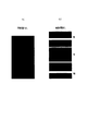
図8は、インク滴を吐出したときの印刷結果を模式的に示している。
想定している位置よりも上下にずれた位置に着弾するので、図8(a)に示すような同一濃度の矩形形状の印刷画像は、図8(b)に示すように、副走査方向において中央部分よりも上端側と下端側とで濃度が薄くなる。着弾位置上下に開く結果、濃度が粗となるからである。
FIG. 8 schematically shows a printing result when ink droplets are ejected.
Since the landing is performed at a position shifted up and down from the assumed position, a rectangular printed image having the same density as shown in FIG. 8 (a) is obtained in the sub-scanning direction as shown in FIG. 8 (b). The concentration is lower on the upper end side and the lower end side than on the central part. This is because the density becomes coarse as a result of opening up and down the landing position.
このような気流の影響を避けようとする手法として、本発明では、比較的小ドットのものが先行ノズル列から吐出されるような状況に対し、後行ノズル列から吐出されるような補正を行う。
ただし、全てのドットを対象とすると精密な処理を経て決定されたドットイメージから大きくずれてしまうこともあり得るので、あくまでも設定された割合の範囲に該当するドットだけを補正の対象とする。ステップS114では、割合判定して対象とするかを判断する。例えば、先行ノズル列から小ドットが吐出されるもののうち、60%までは補正の対象とすると設定すれば、先行ノズル列から小ドットが吐出されると判断されたときに乱数発生させて60%以内か特定し、60%以内であれば、ステップS116にて、小ドットを移動処理(補正、交換)させる。上述したように、ドットイメージ上では、一画素だけ上または下に移動させれば、先行ノズル列から吐出されるはずであった小ドットは後行ノズル列から吐出されることになるし、逆に、後行ノズル列から吐出されるはずであった小ドットは先行ノズル列から吐出されることになる。
As a method for avoiding the influence of such an air flow, in the present invention, in the situation where relatively small dots are ejected from the leading nozzle row, a correction is made so as to eject from the trailing nozzle row. Do.
However, if all the dots are targeted, the dot image determined through precise processing may deviate significantly. Therefore, only the dots corresponding to the set ratio range are targeted for correction. In step S114, the ratio is determined to determine whether or not to target. For example, if it is set that up to 60% of the small dots ejected from the preceding nozzle row are to be corrected, a random number is generated when it is determined that the small dots are ejected from the preceding nozzle row, and 60%. If it is within 60%, the small dots are moved (corrected or replaced) in step S116. As described above, on the dot image, if only one pixel is moved up or down, the small dots that should have been ejected from the preceding nozzle row will be ejected from the trailing nozzle row, and vice versa. In addition, the small dots that were supposed to be ejected from the trailing nozzle row will be ejected from the leading nozzle row.
むろん、1パス印刷していたものを2パス印刷することで、予定されていた同じノズルから吐出させつつも先行ではなく後行の状態で吐出させることは可能である。しかし、2パス印刷するので印刷時間が倍増する。
次に、ステップS118では、後行で大ドットがあるか判定する。大ドットは気流の影響を受けにくいため、後行ノズル列から吐出されるはずの大ドットを先行ノズル列から吐出させる。小ドットの場合と同様に、ステップS120では、予め設定しておいた割合に基づき、割合判定して対象とするか否かを決める。この割合は、小ドットのものと同じであっても良いし、異ならせても良い。小ドットでの判定と同様に割合判定して対象とするのであれば、ステップS122にて、移動処理(補正、交換)を行なう。すなわち、後行ノズル列の大ドットを上下の画素位置に移動させることにより、先行ノズル列から吐出させるように補正する。
以上のようにして、ステップS112〜S118の処理を経て、先行ノズルの小ドットは後行ノズルに補正し、後行ノズルの大ドットは先行ノズルに補正しており、かかる処理は、第1ドットおよび第2ドットが前記主走査方向における先行ノズル列および後行ノズル列のどちらに該当するかに応じて、第1ドットおよび第2のドットのデータを補正して補正データを生成し、当該補正データに基づいて前記印刷データを生成する印刷データ生成部に相当する。
Of course, by printing two passes of what was printed in one pass, it is possible to eject from the same nozzle as planned, but in a state of trailing instead of leading. However, since 2-pass printing is performed, the printing time is doubled.
Next, in step S118, it is determined whether or not there is a large dot in the subsequent line. Since the large dots are not easily affected by the air flow, the large dots that should be ejected from the trailing nozzle row are ejected from the leading nozzle row. As in the case of the small dots, in step S120, the ratio is determined based on the preset ratio, and it is determined whether or not to target. This ratio may be the same as that of the small dots, or may be different. If the ratio is determined and the target is determined in the same manner as the determination with small dots, the movement process (correction, exchange) is performed in step S122. That is, by moving the large dots in the trailing nozzle row to the upper and lower pixel positions, the nozzles are corrected so as to be ejected from the leading nozzle row.
As described above, through the processes of steps S112 to S118, the small dots of the leading nozzle are corrected to the trailing nozzle, and the large dots of the trailing nozzle are corrected to the leading nozzle. And, depending on whether the second dot corresponds to the leading nozzle row or the trailing nozzle row in the main scanning direction, the data of the first dot and the second dot is corrected to generate the correction data, and the correction is performed. It corresponds to a print data generation unit that generates the print data based on the data.
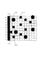
図9は、補正前のハーフトーン処理後のドットデータを模式的に示している。また、図10は、補正の処理の様子を模式的に示している。
図9の左方にはノズル列とノズル番号を示している。一番上のH1はノズル列Hの上から1番目のノズルを示している。以下、ノズル列Aの1番目のノズル、ノズル列Hの2番目のノズル、、、という具合である。右方に示す各升目は各画素の位置(ドット位置)を示している。以下、説明の便宜上、(x、y)座標で位置を示すものとし、左上の升目を原点(1,1)として、右方をx座標、下方をy座標として一升目ごとにそれぞれ1ずつ増加するものとする。
FIG. 9 schematically shows the dot data after the halftone processing before the correction. Further, FIG. 10 schematically shows a state of correction processing.
The nozzle row and the nozzle number are shown on the left side of FIG. The top H1 indicates the first nozzle from the top of the nozzle row H. Hereinafter, the first nozzle of the nozzle row A, the second nozzle of the nozzle row H, and so on. Each square shown on the right indicates the position (dot position) of each pixel. Hereinafter, for convenience of explanation, the position is indicated by the (x, y) coordinates, the upper left square is the origin (1,1), the right side is the x coordinate, and the lower side is the y coordinate, and each square is incremented by 1. It shall be.
升目をはみ出る大きな丸は大ドットであり、升目に納まる小さな丸は小ドットである。これによりドットサイズの情報を表している。
このドットデータを前提として、図3に示すように印刷ヘッド17が左方に移動する場合は、ノズル列Hが先行ノズル列であり、ノズル列Aが後行ノズル列となる。先行ノズル列に含まれるノズルH1に着目すると、(5,1)のドット位置に小ドットが付されることになる。便宜上、割合判定を無視すると、先行ノズル列に小ドットを付す状況であるから、ステップS112の判定を経て、ステップS116にて移動処理の対象となる。図10に示すように、この小ドットを(5,2)のドット位置に移動させると、ノズル列Aに割り振られるので、気流の影響を受けない後行ノズル列から吐出されることになる。
The large circles that stick out of the squares are large dots, and the small circles that fit in the squares are small dots. This represents the dot size information.
On the premise of this dot data, when the print head 17 moves to the left as shown in FIG. 3, the nozzle row H is the leading nozzle row and the nozzle row A is the trailing nozzle row. Focusing on the nozzle H1 included in the preceding nozzle row, small dots are added to the dot positions of (5, 1). For convenience, if the ratio determination is ignored, a small dot is added to the preceding nozzle row. Therefore, after the determination in step S112, the movement process is performed in step S116. As shown in FIG. 10, when the small dots are moved to the dot positions of (5, 2), they are assigned to the nozzle row A, so that they are discharged from the trailing nozzle row that is not affected by the air flow.
同様の判断を受けるのがノズルH3の(2,5)の小ドット、ノズルH4の(1,7)の小ドット、およびノズルH5の(2,9)の小ドットであり、それぞれ(2,4)、(1,6)、(2,10)のドット位置に移動させれば、後行のノズル列Aから吐出されることになる。
また、大ドットについては、図9を参照すると、(2,2)のドット位置に大ドットが付されるはずである。このドット位置はノズルA2から吐出されるので後行ノズル列からの吐出となる。従って、ステップS118の判定を経て、かつ、割合判定を無視すると、ステップS122にて移動処理の対象となる。具体的には、(2,2)のドット位置から(2,1)のドット位置へ移動させることでノズルH1からの吐出となり、先行ノズル列から吐出されるようになる。
The small dots of nozzle H3 (2, 5), the small dots of nozzle H4 (1, 7), and the small dots of nozzle H5 (2, 9) receive the same judgment, respectively (2,). If it is moved to the dot positions of 4), (1,6), and (2,10), it will be ejected from the nozzle row A in the subsequent row.
As for the large dots, referring to FIG. 9, the large dots should be added at the dot positions of (2, 2). Since this dot position is ejected from the nozzle A2, it is ejected from the trailing nozzle row. Therefore, if the determination in step S118 is passed and the ratio determination is ignored, the movement process is performed in step S122. Specifically, by moving from the dot position of (2,2) to the dot position of (2,1), the nozzle H1 is discharged, and the nozzle is discharged from the preceding nozzle row.
このような補正を経たドットデータは、通常は当該データに基づいて印刷ヘッド17の各ノズルを駆動するための駆動信号の制御に使用される。この駆動信号の制御の処理が最終的な印刷データ生成処理に相当する。PC40が前記処理を実行する場合、所定のプログラムを実施して前記処理を実現するPC40は前記ハーフトーン生成部と印刷データ生成部に相当し、これらを含む画像処理装置にも相当する。補正ドットデータの生成までをPC40で行い、その補正データをプリンター10が受けて駆動信号の生成を担当することも可能である。
The dot data that has undergone such correction is usually used for controlling a drive signal for driving each nozzle of the print head 17 based on the data. This drive signal control process corresponds to the final print data generation process. When the PC 40 executes the process, the PC 40 that implements the process by executing a predetermined program corresponds to the halftone generation unit and the print data generation unit, and also corresponds to an image processing device including these. It is also possible that the PC 40 performs up to the generation of the correction dot data, and the
以上の説明は、PC40のプリンタードライバーが印刷データを生成した。一方、プリンター10がネットワーク30を介して中間印刷言語を受信し、プリンター10自身が印刷データを処理する場合もある。この場合は、上述した処理をプリンター10内の制御回路20が担えばよい。
プリンター内の制御回路20は、上述したPC40の場合と同様、ハーフトーン生成部と印刷データ生成部に相当し、これらを含む画像処理装置にも相当する。画像処理装置が実施する前記処理の各工程により画像処理方法を構成する。また、前記PC40や制御回路20に上述した処理を実施させるプログラムは画像処理プログラムに相当し、同プログラムを記録するROMやハードディスクなどが画像処理プログラムを記録した媒体に相当する。むろん、これら以外の媒体でも実現可能である。
In the above description, the printer driver of the PC 40 generated the print data. On the other hand, the
The
(第2実施形態)
第1実施形態では、ハーフトーン処理で生成したドットデータを補正することで、気流の影響を受けにくいドットデータとしている。
一方で、このような補正をハーフトーン処理の過程で実現することも可能である。すなわち、RGB多値データである画像データから、第1ドットおよびこの第1ドットより大きい第2ドットを含むドットサイズおよびドット位置を有するCMYK二値データであるドットデータを生成する際に、第1ドットおよび第2ドットが主走査方向における先行ノズル列および後行ノズル列のどちらに該当するかに応じて、第1ドットおよび第2ドットのドットデータを補正してドットデータを生成する。
(Second Embodiment)
In the first embodiment, the dot data generated by the halftone processing is corrected so that the dot data is not easily affected by the air flow.
On the other hand, it is also possible to realize such a correction in the process of halftone processing. That is, when generating dot data which is CMYK binary data having a dot size and a dot position including a first dot and a second dot larger than the first dot from the image data which is RGB multi-value data, the first The dot data of the first dot and the second dot is corrected to generate the dot data according to whether the dot and the second dot correspond to the leading nozzle row or the trailing nozzle row in the main scanning direction.
上述した例と同様に、小ドットが先行ノズル列から吐出されるドットデータとならないように、ハーフトーン処理を行う過程で後行ノズル列から吐出される位置に小ドットを発生させる。
例えば、記録方法によっては印刷ヘッド17と用紙の相対的な移動を予め決めておくことができるため、ドットデータを生成するにあたり、各ドット位置が既に印刷ヘッド17のノズルと対応することになる。従って、ドット位置ごとに印刷ヘッド17が何パス目の往路か復路のどちらで印刷することになるか、そのときに先行ノズル列になるのか後行ノズル列になるのかも特定できる。
Similar to the above example, small dots are generated at positions ejected from the trailing nozzle row in the process of performing the halftone process so that the small dots do not become the dot data ejected from the preceding nozzle row.
For example, depending on the recording method, the relative movement of the print head 17 and the paper can be determined in advance, so that each dot position already corresponds to the nozzle of the print head 17 when generating dot data. Therefore, for each dot position, it is possible to specify on which pass the print head 17 prints on the outward path or the return path, and at that time, whether it is the leading nozzle row or the trailing nozzle row.
その「ノズルマップ」を参照してディザマスクを設計すればよい。例えば、「小ドットは、往路の後行列ノズルを使う位置から先に発生させ、大ドットは、往路の先行列ノズルの位置から先に発生させる」、というディザマスクを作ればよい。
このディザマスクを使用してハーフトーン処理をすれば、個別の補正する処理はしないものの、一度のディザマスクの適用により、上述した内容を実施したドットデータを生成することになる。
The dither mask may be designed with reference to the "nozzle map". For example, a dither mask may be created such that "small dots are generated first from the position where the back-matrix nozzle on the outbound route is used, and large dots are generated first from the position of the front-matrix nozzle on the outbound route".
If halftone processing is performed using this dither mask, individual correction processing is not performed, but by applying the dither mask once, dot data in which the above-mentioned contents are performed will be generated.
(第3の実施形態)
図3に示すように、シアンの色インクを吐出するノズル列H列とA列の間隔は比較的大きく、ブラックの色インクを吐出するノズル列E列とD列の間隔は比較的小さい。また、図7に示すように、シアンの色インクを吐出するノズル列H列とA列とではインク滴が上下に延びることによる差が比較的大きいが、ブラックの色インクを吐出するノズル列E列とD列とではインク滴が上下に延びることによる差が比較的小さい。
(Third Embodiment)
As shown in FIG. 3, the distance between the nozzle rows H and A for ejecting cyan color ink is relatively large, and the distance between the nozzle rows E and D for ejecting black color ink is relatively small. Further, as shown in FIG. 7, there is a relatively large difference between the nozzle rows H and A for ejecting cyan color ink due to the ink droplets extending vertically, but the nozzle row E for ejecting black color ink is relatively large. The difference between the row and the row D due to the ink droplets extending vertically is relatively small.
これは図7に示すようにノズル列の間隔に概ね比例している。従って、ノズル列の間隔が大きな色にだけ上述した処理を適用し、ノズル列の間隔が小さな色には上述した処理を省略して処理時間の短縮を図ることもできる。判定は、所定のしきい値を設定しておき、間隔がこのしきい値を超えるか否かで判断すればよい。
すなわち、インク色によって先行ノズル列と後行ノズル列との間隔が異なる場合、所定の距離よりも長いインク色について、ドットデータに補正する。
This is roughly proportional to the spacing of the nozzle rows as shown in FIG. Therefore, the above-mentioned processing can be applied only to the colors having a large nozzle row spacing, and the above-mentioned processing can be omitted for the colors having a small nozzle row spacing to shorten the processing time. The determination may be made by setting a predetermined threshold value and determining whether or not the interval exceeds this threshold value.
That is, when the distance between the leading nozzle row and the trailing nozzle row differs depending on the ink color, the ink color longer than a predetermined distance is corrected to dot data.
(第4の実施形態)
気流は印刷ヘッド17の移動によって生じるものであるから、印刷ヘッド17の速度も気流やそれによる風紋にも影響を及ぼす。一般に、印刷ヘッド17は速度はインク滴の着弾位置を左右するものであり、印刷ヘッド17の速度管理は制御回路20によって行っている。このため、印刷ヘッドの移動速度が大きいときに上述した処理を行うようにしてもよい。この場合も所定のしきい値を比較すればよい。
(Fourth Embodiment)
Since the airflow is generated by the movement of the print head 17, the speed of the print head 17 also affects the airflow and the resulting wind pattern. In general, the speed of the print head 17 affects the landing position of ink droplets, and the speed of the print head 17 is controlled by the
移動速度は、速度そのものを検知してもよいし、移動速度を決定する段階の指標値や制御信号に基づいて移動速度を間接的に検知してもよい。例えば、印刷ヘッド17の移動範囲が短い場合には最大速度に達しないこともあり得るし、移動範囲が長い場合には常に所定の定速度と判断して移動速度を所定値とみなしてもよい。
このように、印刷ヘッドの移動速度に対応するパラメータを検出し、移動速度が大きいときに、先行ノズル列で吐出させるドットデータを後行ノズル列で吐出させるドットデータに補正し、または、後行ノズル列で吐出させるドットデータを先行ノズル列で吐出させるドットデータに補正する。
As the moving speed, the speed itself may be detected, or the moving speed may be indirectly detected based on an index value or a control signal at a stage of determining the moving speed. For example, if the movement range of the print head 17 is short, the maximum speed may not be reached, and if the movement range is long, it may always be determined that the print head 17 has a predetermined constant speed and the movement speed may be regarded as a predetermined value. ..
In this way, the parameter corresponding to the moving speed of the print head is detected, and when the moving speed is high, the dot data discharged by the leading nozzle row is corrected to the dot data discharged by the trailing nozzle row, or the trailing row The dot data discharged by the nozzle row is corrected to the dot data discharged by the preceding nozzle row.
なお、本発明は前記実施例に限られるものでないことは言うまでもない。当業者であれば言うまでもないことであるが、
・前記実施例の中で開示した相互に置換可能な部材および構成等を適宜その組み合わせを変更して適用すること
・前記実施例の中で開示されていないが、公知技術であって前記実施例の中で開示した部材および構成等と相互に置換可能な部材および構成等を適宜置換し、またその組み合わせを変更して適用すること
・前記実施例の中で開示されていないが、公知技術等に基づいて当業者が前記実施例の中で開示した部材および構成等の代用として想定し得る部材および構成等と適宜置換し、またその組み合わせを変更して適用すること
は本発明の一実施例として開示されるものである。
Needless to say, the present invention is not limited to the above examples. Needless to say, if you are a person skilled in the art,
-Applying the mutually replaceable members and configurations disclosed in the above-described embodiment by appropriately changing the combination thereof.-Although not disclosed in the above-mentioned embodiment, it is a known technique and the above-mentioned embodiment. The members and configurations that are mutually replaceable with the members and configurations disclosed in the above are appropriately replaced, and the combinations thereof are changed and applied. It is an embodiment of the present invention to appropriately replace the members and configurations that can be assumed as substitutes for the members and configurations disclosed by those skilled in the art based on the above, and to change and apply the combinations thereof. Is disclosed as.
10…プリンター(印刷装置)、12…プラテン、13…プラテンモーター、14…フィードモーター、15…給紙ローラー、16…操作パネル・表示部、17…印刷ヘッド、17−1,17−2…ヘッド、18…キャリッジモーター、19…ベルト、20…制御回路。 10 ... Printer (printing device), 12 ... Platen, 13 ... Platen motor, 14 ... Feed motor, 15 ... Paper feed roller, 16 ... Operation panel / display, 17 ... Print head, 17-1, 17-2 ... Head , 18 ... Carriage motor, 19 ... Belt, 20 ... Control circuit.
Claims (10)
前記画像データから、ドットデータを生成するハーフトーン処理部と、前記ドットデータに基づいて前記印刷データを生成する印刷データ生成部とを備え、
第1ドットおよび前記第1ドットより大きい第2ドットを含むドットサイズおよびドット位置を有するドットデータを生成する際に、第1ドットおよび第2ドットが前記主走査方向における先行ノズル列および後行ノズル列のどちらに該当するかに応じて、第1ドットおよび第2ドットのドットデータを補正することを特徴とする画像処理装置。 It is movable in the main scanning direction relative to the medium, and has a head provided with a plurality of nozzles for ejecting ink of the same color to form dots in the main scanning direction, and each dot has a different size. An image processing device that generates print data for a printing device on which dots are formed from image data.
A halftone processing unit that generates dot data from the image data and a print data generation unit that generates the print data based on the dot data are provided.
When generating dot data having a dot size and a dot position including a first dot and a second dot larger than the first dot, the first dot and the second dot are a leading nozzle row and a trailing nozzle in the main scanning direction. An image processing apparatus characterized in that the dot data of the first dot and the second dot is corrected according to which of the columns is applicable.
前記印刷データ生成部は、第1ドットおよび第2ドットが前記主走査方向における先行ノズル列および後行ノズル列のどちらに該当するかに応じて、第1ドットおよび第2のドットのデータを補正して補正データを生成し、当該補正データに基づいて前記印刷データを生成することを特徴とする請求項1に記載の画像処理装置。 The halftone processing unit generates dot data having a dot size and a dot position including a first dot and a second dot larger than the first dot from the image data.
The print data generation unit corrects the data of the first dot and the second dot according to whether the first dot and the second dot correspond to the leading nozzle row or the trailing nozzle row in the main scanning direction. The image processing apparatus according to claim 1, wherein the correction data is generated, and the print data is generated based on the correction data.
前記画像データから、ドットデータを生成するハーフトーン処理と、前記ドットデータに基づいて、前記印刷データを生成する印刷データ生成とを実行するときに、
前記ハーフトーン処理と前記印刷データ生成とのいずれかにおいて、
第1ドットおよび前記第1ドットより大きい第2ドットを含むドットサイズおよびドット位置を有するドットデータを生成する際に、第1ドットおよび第2ドットが前記主走査方向における先行ノズル列および後行ノズル列のどちらに該当するかに応じて、第1ドットおよび第2ドットのドットデータを補正することを特徴とする画像処理方法。 Print data for a printing device that is movable in the main scanning direction relative to the medium and has a head provided with a plurality of nozzles for ejecting ink of the same color to form dots in the main scanning direction. , An image processing method generated from image data,
When executing halftone processing for generating dot data from the image data and print data generation for generating the print data based on the dot data,
In either the halftone processing or the print data generation,
When generating dot data having a dot size and a dot position including a first dot and a second dot larger than the first dot, the first dot and the second dot are a leading nozzle row and a trailing nozzle in the main scanning direction. An image processing method characterized in that the dot data of the first dot and the second dot is corrected according to which of the columns is applicable.
Priority Applications (2)
| Application Number | Priority Date | Filing Date | Title |
|---|---|---|---|
| JP2016222950A JP6885023B2 (en) | 2016-11-16 | 2016-11-16 | Image processing device and image processing method |
| US15/805,552 US10265954B2 (en) | 2016-11-16 | 2017-11-07 | Image processing apparatus and image processing method |
Applications Claiming Priority (1)
| Application Number | Priority Date | Filing Date | Title |
|---|---|---|---|
| JP2016222950A JP6885023B2 (en) | 2016-11-16 | 2016-11-16 | Image processing device and image processing method |
Publications (2)
| Publication Number | Publication Date |
|---|---|
| JP2018079614A JP2018079614A (en) | 2018-05-24 |
| JP6885023B2 true JP6885023B2 (en) | 2021-06-09 |
Family
ID=62107201
Family Applications (1)
| Application Number | Title | Priority Date | Filing Date |
|---|---|---|---|
| JP2016222950A Active JP6885023B2 (en) | 2016-11-16 | 2016-11-16 | Image processing device and image processing method |
Country Status (2)
| Country | Link |
|---|---|
| US (1) | US10265954B2 (en) |
| JP (1) | JP6885023B2 (en) |
Cited By (1)
| Publication number | Priority date | Publication date | Assignee | Title |
|---|---|---|---|---|
| US11917115B1 (en) | 2023-03-10 | 2024-02-27 | Ricoh Company, Ltd. | Shift compensation mechanism |
Families Citing this family (9)
| Publication number | Priority date | Publication date | Assignee | Title |
|---|---|---|---|---|
| US11014385B2 (en) | 2018-04-16 | 2021-05-25 | Brother Kogyo Kabushiki Kaisha | Liquid discharge apparatus |
| JP7247716B2 (en) * | 2019-04-01 | 2023-03-29 | ブラザー工業株式会社 | Liquid ejector |
| JP7196643B2 (en) * | 2019-01-30 | 2022-12-27 | ブラザー工業株式会社 | Liquid ejector |
| US10634553B1 (en) | 2019-01-30 | 2020-04-28 | Saudi Arabian Oil Company | Hybrid distributed acoustic testing |
| CN115230333B (en) * | 2020-02-27 | 2023-06-09 | 深圳市汉森软件有限公司 | Print data processing method, device, equipment and medium for increasing eclosion area |
| US11519767B2 (en) | 2020-09-08 | 2022-12-06 | Saudi Arabian Oil Company | Determining fluid parameters |
| US11920469B2 (en) | 2020-09-08 | 2024-03-05 | Saudi Arabian Oil Company | Determining fluid parameters |
| US11644351B2 (en) | 2021-03-19 | 2023-05-09 | Saudi Arabian Oil Company | Multiphase flow and salinity meter with dual opposite handed helical resonators |
| US11913464B2 (en) | 2021-04-15 | 2024-02-27 | Saudi Arabian Oil Company | Lubricating an electric submersible pump |
Family Cites Families (13)
| Publication number | Priority date | Publication date | Assignee | Title |
|---|---|---|---|---|
| JP2004142452A (en) * | 2002-10-03 | 2004-05-20 | Canon Inc | Method and apparatus for inkjet recording, and program |
| US7661791B2 (en) * | 2004-06-30 | 2010-02-16 | Lexmark International, Inc. | Apparatus and method for performing mechanical printhead alignment in an imaging apparatus |
| JP4789679B2 (en) * | 2006-03-30 | 2011-10-12 | キヤノン株式会社 | Inkjet recording apparatus and inkjet recording method |
| JP5273919B2 (en) * | 2006-12-12 | 2013-08-28 | キヤノン株式会社 | Inkjet recording method and inkjet recording apparatus |
| JP2010179626A (en) | 2009-02-09 | 2010-08-19 | Canon Inc | Inkjet recording head and inkjet recording device |
| JP5538752B2 (en) * | 2009-06-10 | 2014-07-02 | キヤノン株式会社 | Recording apparatus, recording method, and image processing apparatus |
| EP2287002B1 (en) * | 2009-08-11 | 2012-11-28 | Canon Kabushiki Kaisha | Printing apparatus and printing method |
| US20130100204A1 (en) * | 2011-10-19 | 2013-04-25 | Sam Norasak | Systems for regulating airflow velocity in print gap regions of micro-fluid ejection devices |
| JP2014172349A (en) | 2013-03-12 | 2014-09-22 | Canon Inc | Ink-jet recording apparatus |
| JP6048244B2 (en) * | 2013-03-19 | 2016-12-21 | セイコーエプソン株式会社 | Printing apparatus and printing method |
| JP2015178201A (en) * | 2014-03-19 | 2015-10-08 | セイコーエプソン株式会社 | Printer controller and print control method |
| US20160243827A1 (en) * | 2015-02-24 | 2016-08-25 | Eastman Kodak Company | Controlling air and liquid flows in a two-dimensional printhead array |
| JP6455250B2 (en) * | 2015-03-17 | 2019-01-23 | セイコーエプソン株式会社 | Print control apparatus and print control method |
-
2016
- 2016-11-16 JP JP2016222950A patent/JP6885023B2/en active Active
-
2017
- 2017-11-07 US US15/805,552 patent/US10265954B2/en active Active
Cited By (1)
| Publication number | Priority date | Publication date | Assignee | Title |
|---|---|---|---|---|
| US11917115B1 (en) | 2023-03-10 | 2024-02-27 | Ricoh Company, Ltd. | Shift compensation mechanism |
Also Published As
| Publication number | Publication date |
|---|---|
| US10265954B2 (en) | 2019-04-23 |
| US20180134036A1 (en) | 2018-05-17 |
| JP2018079614A (en) | 2018-05-24 |
Similar Documents
| Publication | Publication Date | Title |
|---|---|---|
| JP6885023B2 (en) | Image processing device and image processing method | |
| US8091977B2 (en) | Inkjet printing apparatus and inkjet printing method | |
| US9561656B2 (en) | Ink-jet printer | |
| US20080266343A1 (en) | Multipass printing method | |
| JP2016172412A5 (en) | ||
| WO2017104721A1 (en) | Printing device and printing method | |
| JP5776348B2 (en) | Image forming apparatus and image forming method | |
| JP4513346B2 (en) | Printing apparatus, printing method, and printing system | |
| CN110816059B (en) | Liquid ejecting apparatus and liquid ejecting method | |
| JP2016147421A (en) | Printing control device and printing control method | |
| JP6552982B2 (en) | Printing apparatus and printing method | |
| JP6054850B2 (en) | Recording apparatus and recording method | |
| JP5972037B2 (en) | Inkjet recording apparatus and inkjet recording method | |
| JP5748522B2 (en) | Inkjet recording apparatus and inkjet recording method | |
| JP6780286B2 (en) | Droplet ejection control device, droplet ejection control method and droplet ejection device | |
| JP6759674B2 (en) | Liquid drop control device, liquid drop control method and liquid drop model | |
| CN113320291B (en) | Data processing method, device, equipment and medium for printing color uniform image | |
| JP7047311B2 (en) | Print control device, print device and print control method | |
| US8926039B2 (en) | Printing device and printing method | |
| US8649060B2 (en) | Method of halftoning for asymmetric print resolutions and a printer | |
| JP2016175191A (en) | Image formation apparatus, image formation method and program | |
| JP2015143012A (en) | Inkjet recording device and image processing device | |
| JP2021160334A (en) | Printing system and printing method | |
| JP2010115846A (en) | Image processing method | |
| WO2016075961A1 (en) | Inkjet printer |
Legal Events
| Date | Code | Title | Description |
|---|---|---|---|
| RD05 | Notification of revocation of power of attorney |
Free format text: JAPANESE INTERMEDIATE CODE: A7425 Effective date: 20180910 |
|
| RD03 | Notification of appointment of power of attorney |
Free format text: JAPANESE INTERMEDIATE CODE: A7423 Effective date: 20190402 |
|
| A621 | Written request for application examination |
Free format text: JAPANESE INTERMEDIATE CODE: A621 Effective date: 20190904 |
|
| RD07 | Notification of extinguishment of power of attorney |
Free format text: JAPANESE INTERMEDIATE CODE: A7427 Effective date: 20200803 |
|
| A977 | Report on retrieval |
Free format text: JAPANESE INTERMEDIATE CODE: A971007 Effective date: 20200805 |
|
| A131 | Notification of reasons for refusal |
Free format text: JAPANESE INTERMEDIATE CODE: A131 Effective date: 20200915 |
|
| A521 | Request for written amendment filed |
Free format text: JAPANESE INTERMEDIATE CODE: A523 Effective date: 20201105 |
|
| TRDD | Decision of grant or rejection written | ||
| A01 | Written decision to grant a patent or to grant a registration (utility model) |
Free format text: JAPANESE INTERMEDIATE CODE: A01 Effective date: 20210413 |
|
| A61 | First payment of annual fees (during grant procedure) |
Free format text: JAPANESE INTERMEDIATE CODE: A61 Effective date: 20210426 |
|
| R150 | Certificate of patent or registration of utility model |
Ref document number: 6885023 Country of ref document: JP Free format text: JAPANESE INTERMEDIATE CODE: R150 |