JP6866135B2 - Airtight seat mounting method and airtight structure - Google Patents
Airtight seat mounting method and airtight structure Download PDFInfo
- Publication number
- JP6866135B2 JP6866135B2 JP2016233336A JP2016233336A JP6866135B2 JP 6866135 B2 JP6866135 B2 JP 6866135B2 JP 2016233336 A JP2016233336 A JP 2016233336A JP 2016233336 A JP2016233336 A JP 2016233336A JP 6866135 B2 JP6866135 B2 JP 6866135B2
- Authority
- JP
- Japan
- Prior art keywords
- sheet material
- airtight
- floor panel
- airtight sheet
- heat insulating
- Prior art date
- Legal status (The legal status is an assumption and is not a legal conclusion. Google has not performed a legal analysis and makes no representation as to the accuracy of the status listed.)
- Active
Links
- 238000000034 method Methods 0.000 title claims description 24
- 239000000463 material Substances 0.000 claims description 272
- 230000000630 rising effect Effects 0.000 claims description 39
- 239000011810 insulating material Substances 0.000 description 8
- 238000010276 construction Methods 0.000 description 4
- 238000009413 insulation Methods 0.000 description 4
- 230000004048 modification Effects 0.000 description 4
- 238000012986 modification Methods 0.000 description 4
- 239000011347 resin Substances 0.000 description 4
- 229920005989 resin Polymers 0.000 description 4
- -1 polyethylene Polymers 0.000 description 3
- 239000004743 Polypropylene Substances 0.000 description 2
- 229920001155 polypropylene Polymers 0.000 description 2
- 238000009751 slip forming Methods 0.000 description 2
- JOYRKODLDBILNP-UHFFFAOYSA-N Ethyl urethane Chemical compound CCOC(N)=O JOYRKODLDBILNP-UHFFFAOYSA-N 0.000 description 1
- 241000884009 Hyporhamphus unifasciatus Species 0.000 description 1
- 239000004698 Polyethylene Substances 0.000 description 1
- 239000000853 adhesive Substances 0.000 description 1
- 230000001070 adhesive effect Effects 0.000 description 1
- 238000005452 bending Methods 0.000 description 1
- 230000001771 impaired effect Effects 0.000 description 1
- 229920000573 polyethylene Polymers 0.000 description 1
- 239000007779 soft material Substances 0.000 description 1
- 230000002269 spontaneous effect Effects 0.000 description 1
Images


Description
本発明は、気密シート取付方法及び気密構造に係り、特に断熱基礎用の気密シート取付方法及び気密構造に関する。 The present invention relates to an airtight sheet mounting method and an airtight structure, and more particularly to an airtight sheet mounting method and an airtight structure for a heat insulating foundation.
寒冷地用の建物には、基礎に断熱材が取り付けられた断熱基礎仕様のものが一般に用いられる様になっている。
このように、建物を断熱基礎仕様とする場合には、床下空間までを気密空間とする必要がある。
このような壁の内壁側の近傍における床の取り合い部分に気密ラインの形成する技術として、特許文献1には、気密部材と断熱部材とが一体となった気密シート(同文献には、断熱気密部材と記載。)を用いる技術が開示されている。この気密シートは、基礎の上部から軸組み、床パネル、内壁枠へと断熱気密ラインを形成するものである。
For buildings for cold regions, those with a heat insulating foundation with a heat insulating material attached to the foundation are generally used.
In this way, when the building has a heat insulating foundation specification, it is necessary to make the space under the floor an airtight space.
As a technique for forming an airtight line in the floor connecting portion in the vicinity of the inner wall side of such a wall,
しかし、断熱基礎と床と壁とが取合う、納まりが複雑な部分に、特許文献1の気密シートを取り付けることは取り合いの関係上困難であり、施工性を損ねる問題があった。
また、気密シートを取り付け可能なスペースが柱等によって分断されることがあり、効率的に取付作業を行うことが困難であった。
However, it is difficult to attach the airtight sheet of
In addition, the space where the airtight sheet can be attached may be divided by pillars or the like, and it is difficult to carry out the attachment work efficiently.
本発明は、上記の課題に鑑みてなされたものであり、本発明の目的は、気密処理の施工性を高めることが可能な気密シート取付方法及び気密構造を提供することにある。
また、本発明の目的は、柱等の近傍における気密処理の施工性を高めることが可能な気密シート取付方法及び気密構造を提供することにある。
The present invention has been made in view of the above problems, and an object of the present invention is to provide an airtight sheet mounting method and an airtight structure capable of improving the workability of the airtight treatment.
Another object of the present invention is to provide an airtight sheet mounting method and an airtight structure capable of improving the workability of the airtight treatment in the vicinity of a pillar or the like.
前記課題は、本発明の気密シート取付方法によれば、建物が備える断熱基礎の立上り部と床パネルとの間、及び該床パネルと内壁との間に気密シートを取り付ける気密シート取付方法であって、第1シート材を、前記断熱基礎の前記立上り部よりも屋内側から前記立上り部の上方に渡って取り付ける第1シート材取付工程と、該第1シート材取付工程の後、前記床パネルの側面が前記第1シート材の一部である対向部に対向するように、前記床パネルを取り付ける床パネル取付工程と、該床パネル取付工程の後、第2シート材を、前記第1シート材の前記対向部に前記第2シート材の一部である重なり部を重ねつつ、前記床パネルの上面側に渡って取り付ける第2シート材取付工程と、該第2シート材取付工程の後、前記第2シート材における前記床パネルの上面の少なくとも一部を覆う部位の上に前記内壁を取り付ける内壁取付工程と、を備えること、により解決される。
上記構成によれば、建物が備える断熱基礎の立上り部よりも屋内側から立上り部の上方に第1シート材を床パネルの側面に一部が対向するように取り付け、第2のシート材を、第1シート材の対向部に重なり部が重なるように取り付け、第2シート材における床パネルの上面の少なくとも一部を覆う部位の上に内壁を取り付けることで、気密構造を容易に形成することができ、気密処理の施工性を高めることができる。
According to the airtight sheet mounting method of the present invention, the problem is an airtight sheet mounting method for mounting an airtight sheet between a rising portion of a heat insulating foundation provided in a building and a floor panel, and between the floor panel and an inner wall. After the first sheet material mounting step of mounting the first sheet material from the indoor side of the heat insulating foundation above the rising portion and the first sheet material mounting step, the floor panel After the floor panel mounting step of mounting the floor panel and the floor panel mounting step so that the side surface of the floor panel faces the facing portion which is a part of the first sheet material, the second sheet material is attached to the first sheet. After the second sheet material mounting step of mounting the overlapping portion, which is a part of the second sheet material, on the facing portion of the material over the upper surface side of the floor panel, and the second sheet material mounting step. The solution is to include an inner wall mounting step of mounting the inner wall on a portion of the second sheet material that covers at least a part of the upper surface of the floor panel.
According to the above configuration, the first sheet material is attached from the indoor side to the upper part of the rising part of the heat insulating foundation provided in the building so as to partially face the side surface of the floor panel, and the second sheet material is attached. An airtight structure can be easily formed by attaching the first sheet material so that the overlapping portion overlaps the facing portion and attaching the inner wall on the portion of the second sheet material that covers at least a part of the upper surface of the floor panel. It is possible to improve the workability of airtight treatment.
また、前記第1シート材取付工程の前において、前記第1シート材が前記断熱基礎の前記立上り部よりも屋内側から前記立上り部の上端の上方に渡って延在し、前記第1シート材の前記対向部が前記床パネルの側面に対向するように前記第1シート材を折り曲げるようにしてもよい。
上記構成によれば、第1シート材取付工程の前に、第1シート材を折り曲げることで、取り付けに適した所定の形状にして、第1シート材を所定位置に配することができる。
Further, before the first sheet material attaching step, the first sheet material extends from the indoor side of the heat insulating foundation to above the upper end of the rising portion, and the first sheet material extends above the upper end of the rising portion. The first sheet material may be bent so that the facing portion thereof faces the side surface of the floor panel.
According to the above configuration, by bending the first sheet material before the first sheet material attaching step, the first sheet material can be arranged at a predetermined position in a predetermined shape suitable for attachment.
また、前記第2シート材取付工程において、前記第2シート材が、前記重なり部で前記対向部に重なりつつ、前記床パネルの上面の少なくとも一部を覆うように前記第2シート材を折り曲げるようにするとよい。
上記構成によれば、第2シート材取付工程において、床パネルに内壁取付用の墨打ちをする際に邪魔にならないように、第2シート材が自然状態のときに床パネルの墨打ちし、その後に、第2シート材を折り曲げて取り付けに適した所定の形状にして、所定位置に配することができる。
Further, in the second sheet material attaching step, the second sheet material is bent so as to cover at least a part of the upper surface of the floor panel while overlapping the facing portion at the overlapping portion. It is good to set it to.
According to the above configuration, in the process of attaching the second sheet material, the floor panel is inked when the second sheet material is in a natural state so as not to interfere with the inking of the floor panel for attaching the inner wall. After that, the second sheet material can be bent into a predetermined shape suitable for attachment and arranged at a predetermined position.
また、前記課題は、本発明の気密構造によれば、建物が備える断熱基礎の立上り部と床パネルとの間、及び該床パネルと内壁との間に形成される気密構造であって、前記断熱基礎の前記立上り部よりも屋内側から前記立上り部の上端の上方に渡って取り付けられる部材であり、前記床パネルの側面に対向する対向部を有する第1シート材と、前記対向部に重なる重なり部を有し、前記床パネルの上面側に渡って取り付けられる第2シート材と、から構成され、前記第2シート材における前記床パネルの上面の少なくとも一部を覆う部位の上に、前記内壁が取り付けられていること、により解決される。
上記構成によれば、建物における断熱基礎の立上り部よりも屋内側から立上り部の上端の上方に渡って取り付けられる部材であり、床パネルの側面に対向する対向部を有する第1シート材と、対向部に重なる重なり部を有する第2シート材と、から構成されていることで、容易に形成することが可能な気密構造を提供して、気密処理の施工性を高めることができる。
Further, according to the airtight structure of the present invention, the problem is an airtight structure formed between the rising portion of the heat insulating foundation provided in the building and the floor panel, and between the floor panel and the inner wall. It is a member that is attached from the indoor side of the heat insulating foundation to above the upper end of the rising portion, and overlaps the first sheet material having the facing portion facing the side surface of the floor panel and the facing portion. The second sheet material having an overlapping portion and being attached over the upper surface side of the floor panel is formed on the portion of the second sheet material that covers at least a part of the upper surface of the floor panel. It is solved by the fact that the inner wall is attached.
According to the above configuration, a first sheet material which is a member attached from the indoor side to above the upper end of the rising portion of the heat insulating foundation in the building and has an facing portion facing the side surface of the floor panel. By being composed of a second sheet material having an overlapping portion overlapping the facing portions, an airtight structure that can be easily formed can be provided, and the workability of the airtight treatment can be improved.
また、前記第1シート材及び前記第2シート材が前記建物に取り付けられた状態において、前記第1シート材の前記対向部と前記第2シート材の前記重なり部は、鉛直方向に延在しており、前記建物に設けられた前記床パネルの側面に対向する位置で連結されていると好ましい。
上記構成によれば、第1シート材の対向部、及び第2シート材の重なり部が鉛直方向に延在していることで、床パネルの側面に沿う形状とすることができ、床パネルと干渉して、第1シート材及び第2シート材が変形することを抑制できる。
Further, in a state where the first sheet material and the second sheet material are attached to the building, the facing portion of the first sheet material and the overlapping portion of the second sheet material extend in the vertical direction. It is preferable that the floor panel is connected to the side surface of the floor panel provided in the building at a position facing the side surface.
According to the above configuration, the facing portion of the first sheet material and the overlapping portion of the second sheet material extend in the vertical direction, so that the shape can be formed along the side surface of the floor panel. It is possible to prevent the first sheet material and the second sheet material from being deformed due to interference.
さらに、前記第1シート材及び前記第2シート材のいずれか一方には、屈曲部分に折り目が形成されていてもよい。
上記構成によれば、第1シート材及び前記第2シート材に、折り目が形成されていることで、床パネルに内壁取付用の墨打ちをする際に邪魔にならないよう、墨打ち後に折り曲げて所定位置に配することができ、現場での施工作業を容易にすることができる。
Further, creases may be formed in the bent portion of either the first sheet material or the second sheet material.
According to the above configuration, since the first sheet material and the second sheet material are formed with creases, the floor panel is bent after being inked so as not to interfere with the inking for mounting on the inner wall. It can be placed in a predetermined position, facilitating on-site construction work.
また、前記第2シート材は、前記第1シート材よりも硬質の材料から成るものであると好ましい。
上記構成によれば、第1シート材を施工し、床パネルを施工した後に、第2シート材を床パネルと他の部材の隙間に差し込みやすくなり、施工性を高めることができる。
Further, it is preferable that the second sheet material is made of a material that is harder than the first sheet material.
According to the above configuration, after the first sheet material is installed and the floor panel is installed, the second sheet material can be easily inserted into the gap between the floor panel and other members, and the workability can be improved.
本発明によれば、気密構造を容易に形成することができ、気密処理の施工性を高めることができる。
さらに、突出部位の有無に関わらず容易に気密性を確保することができ、気密処理の施工性を高めることができる。
また、第1シート材を所定位置に配することができる。
また、床パネルに内壁取付用の墨打ちをする際に邪魔にならないよう、床パネルの墨打ち後に第2シート材を折り曲げて所定位置に配することができる。
また、本発明によれば、容易に形成することが可能な気密構造を提供して、気密処理の施工性を高めることができる。
また、床パネルと干渉して、第1シート材及び第2シート材が変形することを抑制できる。
さらに、床パネルに内壁取付用の墨打ちをする際に邪魔にならないよう、墨打ち後に折り曲げて所定位置に配することができ、現場での施工作業を容易にすることができる。
また、気密構造を形成する部分に突出部位がある場合でも、容易に気密性を確保することができる。
また、第1シート材を施工し、床パネルを施工した後に、第2シート材を床パネルと他の部材の隙間に差し込みやすくなり、施工性を高めることができる。
According to the present invention, an airtight structure can be easily formed, and the workability of the airtight treatment can be improved.
Further, the airtightness can be easily ensured regardless of the presence or absence of the protruding portion, and the workability of the airtight treatment can be improved.
In addition, the first sheet material can be arranged at a predetermined position.
In addition, the second sheet material can be bent and placed at a predetermined position after the floor panel is inked so as not to interfere with the inking of the floor panel for mounting on the inner wall.
Further, according to the present invention, it is possible to provide an airtight structure that can be easily formed and improve the workability of the airtight treatment.
In addition, it is possible to prevent the first sheet material and the second sheet material from being deformed due to interference with the floor panel.
Further, the floor panel can be bent and placed at a predetermined position so as not to interfere with the marking of the inner wall for mounting on the floor panel, so that the construction work at the site can be facilitated.
Further, even if there is a protruding portion in the portion forming the airtight structure, the airtightness can be easily ensured.
Further, after the first sheet material is installed and the floor panel is installed, the second sheet material can be easily inserted into the gap between the floor panel and other members, and the workability can be improved.
本発明は、断熱基礎を備える建物に形成される気密構造、及び気密構造を形成するための気密シートを取り付ける気密シート取付方法に関する。
以下に、本発明の実施形態に係る気密構造及び気密シート取付方法について説明する。なお、以下に示す実施形態は、本発明の理解を容易にするためのものであり、本発明を限定するものではない。本発明は、その趣旨を逸脱することなく、変更、改良され得るとともに、本発明には各実施形態、変形例に係る特徴を組み合わせたもの、その等価物が含まれることは勿論である。
The present invention relates to an airtight structure formed in a building provided with a heat insulating foundation, and a method for attaching an airtight sheet for attaching an airtight sheet for forming the airtight structure.
The airtight structure and the airtight sheet mounting method according to the embodiment of the present invention will be described below. The embodiments shown below are for facilitating the understanding of the present invention, and do not limit the present invention. The present invention can be modified and improved without departing from the spirit thereof, and it goes without saying that the present invention includes a combination of features according to each embodiment and modification, and an equivalent thereof.
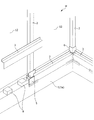
まず、図1を主に参照して外側断熱材1bを有する断熱基礎1を備える本発明に係る建物としての家屋Hにおける、本実施形態に係る気密構造を形成する部位について説明する。なお、図1は、家屋Hの屋内側において、気密構造を形成する部分を示す図であり、下側気密シート材3を取り付けている状態を示す斜視図である。なお、以下において、各部材の説明における屋内側、屋外側は、各部材が家屋Hに取り付けられた状態における屋内側、屋外側を示すものとする。
First, with reference mainly to FIG. 1, a portion forming an airtight structure according to the present embodiment in a house H as a building according to the present invention including a
気密構造は、断熱基礎1の立上り部1aと床パネル10(図12参照)との間、及び床パネル10と内壁パネル13(図14及び図15参照)との間に形成される。
そして、気密構造を構成する主な部材は、気密シート及び第1シート材としての下側気密シート材3、気密シート及び第2シート材としての上側気密シート材4(図2参照)、気密シート及び連結シート材としての柱用気密シート材5及び入隅用気密シート材6である。
The airtight structure is formed between the rising
The main members constituting the airtight structure are an airtight sheet, a lower
<気密構造の構成部材について>
次に、気密構造を構成する各部材について、図2〜図7を主に参照して説明する。ここで、図2は、上下に重ね合わせられる下側気密シート材3と上側気密シート材4とを示す斜視図である。さらに、図3(a)は、上側気密シート材4を示す模式的な側面図、図3(b)は、下側気密シート材3を示す模式的な側面図である。図4は、柱2を覆うように柱用気密シート材5を断熱基礎1に取り付けた状態を示す斜視図、図5は、柱用気密シート材5を示す斜視図であり、図6は、柱用気密シート材5における図5のVI-VI断面を示す断面矢視図である。図7は、入隅用気密シート材6を示す斜視図である。
<About the components of the airtight structure>
Next, each member constituting the airtight structure will be described mainly with reference to FIGS. 2 to 7. Here, FIG. 2 is a perspective view showing a lower
下側気密シート材3と上側気密シート材4は、断熱基礎1の上端部1aa周りにおける直線部分の気密構造を構成する部材であり、ポリエチレン等の硬質樹脂からなる。また、図2及び図3に示すように、断面クランク状に形成されて直線的に延在しており、略面対称の形状であり、上側気密シート材4が下側気密シート材3よりも小さく形成されている。
The lower
下側気密シート材3は、下部3aと、床パネル10(図12参照)の側面10bが対向する対向部としての上部3bと、下部3aの上端部と上部3bの下端部とに垂直に交差してこれらを接続する段差部3cと、から構成され、これらが連続的に形成された板状の部材である。また、下側気密シート材3は、断熱基礎1の立上り部1aよりも屋内側から立上り部1aの上端部1aaの上方に渡って取り付けられる部材である。
The lower
上側気密シート材4は、下側気密シート材3の上部3bに重なる重なり部としての下部4aと、上部4bと、下部4aの上端部と上部4bの下端部とに垂直に交差してこれらを接続する段差部4cと、から構成され、これらが連続的に形成された板状の部材である。上側気密シート材4は、図13に示すように、床パネル10と外壁パネル12との隙間から床パネル10の上面側に渡って取り付けられる部材である。
The upper
柱用気密シート材5は、柱2を覆って気密を確保するための部材である。柱用気密シート材5は、ポリプロピレン等の硬質樹脂からなり、長尺方向の延長上に柱2に跨って複数延在する下側気密シート材3及び上側気密シート材4のそれぞれを連結する部材である。
具体的には、突出部位としての柱2は、家屋Hに取り付けられた下側気密シート材3及び上側気密シート材4の延在方向に交差する方向である屋外から屋内に向かう方向に、外壁パネル12の裏面から突出して形成されている。また、柱2は、下側気密シート材3及び上側気密シート材4の取付位置である、断熱基礎1の立上り部1aの上方であって、外壁パネル12よりも屋内側のスペースに突出して形成されている。下側気密シート材3及び上側気密シート材4のみでは、柱2周りにおいて気密構造を形成するのは困難であるため、柱2周りの気密構造を確保するための特別な形状を有する柱用気密シート材5が設けられている。
The
Specifically, the
柱用気密シート材5は、図5に示すように、下側連結部5aと、ベース側水平部5bと、上側連結部5cと、外側立板部5dと、中央側立板部5eと、内壁側水平部5fと、から構成されており、幅方向における中心面に対して面対称に形成されている。
As shown in FIG. 5, the
下側連結部5aは、その幅方向両端側において、隣接する下側気密シート材3の下部3aにおける長尺方向の端部と重ね合わせられ、下側連結部5a自身を介してこれらを連結するためのものである。下側連結部5aは、略鉛直に延在する平板状に形成されており、断熱基礎1の立上り部1aにおける屋内側の側面に沿った状態で、下端部を気密テープ7によって当該側面に取り付けられる。このようにして、柱用気密シート材5における内外方向(屋内側と屋外側とを結ぶ方向)の位置決めがされて、断熱基礎1に固定される。また、下側連結部5aの上端部から、ベース側水平部5bが屋外側に延在している。
The lower connecting
ベース側水平部5bは、その幅方向両端側において、隣接する下側気密シート材3の段差部3cにおける長尺方向の端部と重ね合わせられ、ベース側水平部5b自身を介してこれらを連結するためのものである。ベース側水平部5bは、上面視凹状に形成されており、略水平に延在している。また、ベース側水平部5bの幅方向中央部から上側連結部5c及び中央側立板部5eが上方に延在しており、ベース側水平部5bの屋外側の端部から、外側立板部5dが上方に延在している。
The base-side
上側連結部5cは、柱2の屋内側を覆いつつ、その幅方向両端側において、隣接する上側気密シート材4の上部4bにおける長尺方向の端部と重ね合わせられ、上側連結部5c自身を介してこれらを連結するためのものである。上側連結部5cは、正面視T字状に形成されており、略鉛直に延在している。また、上側連結部5cの幅方向両側の下端部から内壁側水平部5fが屋外側に延在しており、上側連結部5cの中央側の幅方向両側の端部から、中央側立板部5eが屋外側に延在している。
The upper connecting
外側立板部5dは、幅方向両側において、隣接する下側気密シート材3の上部3b、及び隣接する上側気密シート材4の下部4aのそれぞれにおける長尺方向の端部と重ね合わせられ、外側立板部5d自身を介してこれらを連結するためのものである。外側立板部5dは、正面視方形状に形成されており、略鉛直に延在している。また、外側立板部5dの屋内側の端部から中央側立板部5eが屋内側に延在しており、外側立板部5dの上端部から内壁側水平部5fが屋内側に延在している。
The outer
中央側立板部5eは、柱2における屋内側に交差する側、つまり断熱基礎1の延在方向の両側、を覆うためのものである。つまり、対称に形成された対を成す中央側立板部5eの距離は、柱2における断熱基礎1の延在方向の長さと同じか、若干大きく形成されている。また、中央側立板部5eは、側面視方形状に形成されており、略鉛直に延在している。そして、中央側立板部5eの上端部から内壁側水平部5fが幅方向外側に延在している。
The central side standing
内壁側水平部5fは、幅方向両側において隣接する上側気密シート材4の段差部4cのそれぞれにおける長尺方向の端部と重ね合わせられ、内壁側水平部5f自身を介してこれらを連結するためのものである。内壁側水平部5fは、平面視方形状に形成されており、略水平に延在している。
The inner wall side
また、ベース側水平部5bと内壁側水平部5fとの距離は、下側気密シート材3の段差部3cの厚さと、上側気密シート材4の段差部4cの厚さと、床パネル10の厚さとを加えた長さよりも大きい。さらに、内外方向(屋内と屋外とを結ぶ方向)における、下側連結部5aと外側立板部5dとの距離は、下側気密シート材3の下部3aにおける屋外側の面と上部3bにおける屋外側の面との距離と略等しい。また、上側連結部5cと外側立板部5dとの距離は、上側気密シート材4の下部4aにおける屋外側の面と上部4bにおける屋外側の面との距離と略等しい。
The distance between the base side
このように柱用気密シート材5が形成されていることで、ベース側水平部5bと外側立板部5dと中央側立板部5eと内壁側水平部5fとで形成される凹部5gに、下側気密シート材3の上部3b及び段差部3c、上側気密シート材4の下部4a及び段差部4c並びに床パネル10の縁10cが配設されることとなる。このように、柱用気密シート材5に凹部5gが形成されていることで、床パネル10の縁10cが柱用気密シート材5に入り込むことを可能となる。そして、床パネル10と縁10cと外壁パネル12との間で下側気密シート材3及び上側気密シート材4を挟持できることとなるため、より気密性を高めることができる。
By forming the
入隅用気密シート材6は、家屋Hの入隅部まで延在する下側気密シート材3及び上側気密シート材4のそれぞれを連結することによって気密を確保するための部材であり、ポリプロピレン等の硬質樹脂からなる。
具体的には、家屋Hの入隅部において直交する下側気密シート材3及び上側気密シート材4のそれぞれを連結することは、下側気密シート材3及び上側気密シート材4が段差部3c又は段差部4cを有して形成されているため困難である。このため、入隅部における気密構造を確保するために特別な形状を有する入隅用気密シート材6が設けられている。
The
Specifically, connecting each of the lower
入隅用気密シート材6は、図7に示すように、略鉛直に延在する下部6aと、下部6aに平行に延在する上部6bと、略水平に延在して下部6aの上端部と上部6bの下端部とを接続する段差部6cと、から構成されている。下部6a、上部6b及び段差部6cのそれぞれは、入隅部の柱2の形状に合わせて、平面視L字状に屈曲するように形成されている。入隅用気密シート材6は、入隅部まで延在する下側気密シート材3及び上側気密シート材4が平面視L字状の下部6aの面にそれぞれ突合せられた状態で気密テープ7によって貼り付けられることで、入隅用気密シート材6自身を介してこれらを連結することとなる。
As shown in FIG. 7, the
<気密シートの取付方法について>
次に、図1に加えて、図8〜図16を主に参照して、下側気密シート材3、上側気密シート材4、柱用気密シート材5、入隅用気密シート材6等の取付方法について説明する。
なお、図8は、気密シート取付方法を示すフローチャート図である。図9は、断熱基礎1の上端部1aaに床パネル支持部材8を配置した状態を示す斜視図、図10は、柱用気密シート材5を断熱基礎1の立上り部1aに取り付け、入隅用気密シート材6を入隅部にある柱2に取り付けた状態を示す斜視図である。また、図11は、下側気密シート材3を断熱基礎1の立上り部1aに取り付けた状態を示す断面図、図12は、床パネル10を取り付けた後に、上側気密シート材4を外壁パネル12と床パネル10の間に取り付けている状態を示す斜視図である。また、図13は、上側気密シート材4を外壁パネル12と床パネル10の間に取り付けた状態を示す斜視図である。図14は、内壁パネル13を上側気密シート材4上に取り付けている状態を示す斜視図、図15は、内壁パネル13を上側気密シート材4上に取り付けた状態を示す断面図である。図16は、断熱基礎1の立上り部1aの屋内側に内側断熱材1cを取り付けた状態を示す斜視図である。
<How to attach the airtight sheet>
Next, in addition to FIG. 1, mainly referring to FIGS. 8 to 16, lower
Note that FIG. 8 is a flowchart showing a method of attaching the airtight sheet. FIG. 9 is a perspective view showing a state in which the floor
気密シート取付方法は、図8に示すように、連結シート材取付工程S1、第1シート材取付工程としての下側気密シート材取付工程S2、床パネル取付工程S3、第2シート材取付工程としての上側気密シート材取付工程S4及び内壁パネル取付工程S5によって構成されている。
まず、図9に示す状態においては、断熱基礎1における立上り部1aの上端部1aa上に、下側気密シート材3及び床パネル10を載置するための複数の床パネル支持部材8が取り付けられている。
As shown in FIG. 8, the airtight sheet mounting method includes a connecting sheet material mounting step S1, a lower airtight sheet material mounting step S2 as the first sheet material mounting step, a floor panel mounting process S3, and a second sheet material mounting step. It is composed of the upper airtight sheet material mounting step S4 and the inner wall panel mounting step S5.
First, in the state shown in FIG. 9, a plurality of floor
そして、連結シート材取付工程S1において、図10に示すように、断熱基礎1の直線部分に設けられた柱2を覆うように柱用気密シート材5を配置し、断熱基礎1の入隅に設けられた柱2を覆うように入隅用気密シート材6を配置する。
柱用気密シート材5の下側連結部5aの下端部と立上り部1aの屋内側の側面とに跨るように気密テープ7を貼り付けて、柱用気密シート材5を断熱基礎1に取り付ける。
また、入隅用気密シート材6を立上り部1aの上端部1aaに載せて、上部6bにおける平面視L字状のそれぞれの部位と、入隅部にある柱2における入隅用気密シート材6に対向する2面とに跨るように気密テープ7を貼り付けて、入隅用気密シート材6を柱2に取り付ける。
このように、家屋Hに形成された柱2を柱用気密シート材5及び入隅用気密シート材6で覆い、その後、次に説明するように、下側気密シート材3及び上側気密シート材4を柱用気密シート材5及び入隅用気密シート材6に取り付けることで、柱2の有無に関わらず容易に気密性を確保することができ、気密処理の施工性を高めることができる。
Then, in the connecting sheet material attaching step S1, as shown in FIG. 10, the
An
Further, the
In this way, the
次に、下側気密シート材取付工程S2において、図1及び図11に示すように、下部3aを断熱基礎1の立上り部1aの屋内側から立上り部1aの側面に沿わせつつ、床パネル支持部材8上に下側気密シート材3の段差部3cを載せる。このとき、下側気密シート材3の段差部3cは、立上り部1aの上端部1aaの上方に延在している。
さらに、下部3aの下端部と立上り部1aの屋内側側面に跨るように気密テープ7を貼り付けて、複数の下側気密シート材3を立上り部1aに固定する。また、下側気密シート材3と柱用気密シート材5との重なり部分、及び下側気密シート材3と入隅用気密シート材6との当接部分に、隙間が生じないように気密テープ7を貼り付ける。
Next, in the lower airtight sheet material attaching step S2, as shown in FIGS. 1 and 11, the floor panel is supported while the
Further, the
次に、床パネル取付工程S3において、図12及び図13に示すように、複数の束9の上端部に設けられた載置板9b上、及び床パネル支持部材8の上面を覆う下側気密シート材3上に床パネル10を載置する。このとき床パネル10の側面10bは、下側気密シート材3の上部3bに対向するように配置されることとなる。
なお、束9は、柱部9aと、柱部9aの上端に取り付けられた載置板9bと、から構成されており、床パネル10が取り付けられる前に、立上り部1aよりも屋内側に所定間隔を開けて複数配設されるものである。
Next, in the floor panel mounting step S3, as shown in FIGS. 12 and 13, the lower airtightness covering the mounting
The
そして、上側気密シート材取付工程S4において、上側気密シート材4の下部4aを、外壁パネル12と床パネル10の側面10bとの間に挿し込んで、下側気密シート材3の上部3bの少なくとも一部に重ねる。そして、上側気密シート材4の段差部4cを床パネル10の縁10cの上面10aに沿わせるようにして上側気密シート材4を取り付ける。
なお、上側気密シート材4は、下側気密シート材3よりも硬質の材料から成るものであると、上側気密シート材4を床パネル10と外壁パネル12との隙間に差し込みやすくなり、施工性を高めることができる。
Then, in the upper airtight sheet material attaching step S4, the
If the upper
次に、内壁パネル取付工程S5において、図14及び図15に示すように、床パネル10の墨打ちに合わせて、内壁パネル13を、外壁パネル12の屋内側の面に沿わせて、上側気密シート材4における床パネル10の上面10aの一部を覆う段差部4c上に取り付ける。この際、上側気密シート材4は、床パネル10と内壁パネル13とに上下から挟まれることになるため、取付状態が安定することとなる。
Next, in the inner wall panel mounting step S5, as shown in FIGS. 14 and 15, the
図15に示すように、断熱基礎1の屋内側側面と床パネル10の側面10bと内壁パネル13の屋内側側面とは水平方向において入り組んで配置されている。このような配置であっても、上記構成の下側気密シート材3、上側気密シート材4、柱用気密シート材5及び入隅用気密シート材6を用いた上記取付方法によって、円滑に気密構造を形成することができる。
具体的には、下側気密シート材3の上部3bは、段差部3cから屈曲して鉛直方向に延在しており、と上側気密シート材4の下部4aは、段差部4cから屈曲して鉛直方向に延在しており、それぞれは、床パネル10の側面10bに対向する位置で連結されている。
このように、上部3bが段差部3cから屈曲し、下部4aが段差部4cから屈曲して形成されていることで、床パネル10に沿う形状となり、床パネル10と干渉することによって下側気密シート材3及び上側気密シート材4が変形することを回避できる。
したがって、一旦取り付けた床パネル10及び内壁パネル13について、床パネル10を床パネル支持部材8から持ち上げたり、内壁パネル13を外壁パネル12から離したりすることを要さず、円滑に気密構造を形成でき、気密処理の施工性を高めることができる。
As shown in FIG. 15, the indoor side surface of the
Specifically, the
As described above, the
Therefore, with respect to the
さらに、寒冷地使用の家屋Hにおいては、より断熱性を高めるために、図16に示すように、断熱基礎1の立上り部1aの屋内側側面に、下側気密シート材3の下部3aの一部を覆うように、内側断熱材1cをウレタン系接着剤にて固定してもよい。内側断熱材1cを取り付けは、上側気密シート材取付工程S4の後に行うようにすればよい。
また、下側気密シート材3の下部3aを、内側断熱材1cと立上り部1aの間ではなく、内側断熱材1cの屋内側側面の一部に沿わせて取り付けることが可能な形状としてもよい。
Further, in the house H used in a cold region, in order to further improve the heat insulating property, as shown in FIG. 16, one of the
Further, the
<変形例1>
上記実施形態においては、柱2を覆う気密シートとして、柱用気密シート材5及び入隅用気密シート材6を例に説明したが、本発明はこれらの柱2を覆うものに限定されない。
例えば、図17に示すように、家屋Hの出隅部に設けられた柱2を覆うように、気密シート及び連結シート材としての出隅用気密シート材14を取り付けるようにしてもよい。なお、図17は、出隅用気密シート材14を示す斜視図である。
<Modification example 1>
In the above embodiment, as the airtight sheet for covering the
For example, as shown in FIG. 17, the airtight sheet and the
出隅用気密シート材14は、柱用気密シート材5を幅方向中央部分で二分割して、左部14aと右部14bとを形成したものであり、分割した左部14aと右部14bのそれぞれの上端部を気密テープ7で柱2に取り付けたものである。
このように柱用気密シート材5を二分割することで出隅部に沿って気密構造を容易に形成することが可能となる。さらに、分割部分を覆うように気密テープ7を貼り付けるようにしてもよい。
The
By dividing the
<変形例2>
また、図18に示すように、上側気密シート材4は、自然状態において平板状に形成されており、折り曲げ可能とするための溝状の折り目4d,4eを有するものであってもよい。
このような構成であれば、上側気密シート材取付工程S4において、床パネル10の側面10bに対向する下側気密シート材3の上部3bと外壁パネル12との間に、平板状態の上側気密シート材4を挿し込んだ状態で床パネル10に墨打ちができる。このため、床パネル10の墨打ちに合わせて内壁パネル13の位置決めができる。そして、内壁パネル13の位置決めをした後、床パネル10の縁10cの上面10aを段差部4cが覆う位置まで折り目4dを折り曲げて、上部4bが鉛直に向く位置まで折り目4eを折り曲げる。このようにして、段差部4c上に内壁パネル13を上部4bに沿うように取り付けることができるため、現場での施工作業を容易にすることができる。
<
Further, as shown in FIG. 18, the upper
With such a configuration, in the upper airtight sheet material attaching step S4, the upper airtight sheet in a flat plate state is sandwiched between the
なお、上記同様の折り目が、下側気密シート材3の屈曲部分に形成されていてもよい。下側気密シート材3については、下側気密シート材取付工程S2の前に、折り目を折り曲げるようにすればよい。具体的には、下側気密シート材3が断熱基礎1の立上り部1aよりも屋内側から立上り部1aの上端部1aaの上方に渡って延在し、下側気密シート材3の上部3bが床パネル10の側面10bに対向するように、下側気密シート材3の折り目を折り曲げるようにすればよい。
このようにすることで、下側気密シート材3の取り付けに適した所定の形状にして、下側気密シート材3を所定位置に配することができる。
また、下側気密シート材3及び上側気密シート材4に折り目が形成されていることで、下側気密シート材3及び上側気密シート材4を平板状態で変形しづらい状態で保管ができ、薄く重ね合わせることができるため、収納性を高めることができる。
The same crease as described above may be formed at the bent portion of the lower
By doing so, the lower
Further, since the lower
なお、下側気密シート材3と上側気密シート材4は、硬質樹脂から成ることで、自発的な変形を抑制できることで、周囲の部材との干渉を抑制できるため好ましい。特に、上側気密シート材4を、床パネル10と外壁パネル12との間に差し込む際に、上側気密シート材4が硬質であれば、その形状が安定するため、施工が容易となる。しかしながら、硬質であることに限定されず軟質の材料であってもよい。
Since the lower
上記実施形態においては、内壁パネル13を床パネル10に取り付ける部位の周囲の気密性を高めるための気密シート取付方法及び気密構造について説明したが、本発明は、このような構成に限定されない。例えば、内壁パネル13に限定されず、図示せぬ桟木を、床パネル10を覆う上側気密シート材上に取り付けて、パネル状ではない内壁を取り付けるようにして、その取付部位の周囲の気密性を高めるようにしてもよい。
In the above embodiment, the airtight sheet attachment method and the airtight structure for increasing the airtightness around the portion where the
H 家屋(建物)
1 断熱基礎
1a 立上り部
1aa 上端部
1b 外側断熱材
1c 内側断熱材
2 柱(突出部位)
3 下側気密シート材(気密シート、第1シート材)
3a 下部
3b 上部(対向部)
3c 段差部
4 上側気密シート材(気密シート、第2シート材)
4a 下部(重なり部)
4b 上部
4c 段差部
4d,4e 折り目
5 柱用気密シート材(気密シート、連結シート材)
5a 下側連結部
5b ベース側水平部
5c 上側連結部
5d 外側立板部
5e 中央側立板部
5f 内壁側水平部
5g 凹部
6 入隅用気密シート材(気密シート、連結シート材)
6a 下部
6b 上部
6c 段差部
7 気密テープ
8 床パネル支持部材
9 束
9a 柱部
9b 載置板
10 床パネル
10a 上面
10b 側面
10c 縁
12 外壁パネル
13 内壁パネル(内壁)
14 出隅用気密シート材(気密シート、連結シート材)
14a 左部
14b 右部
H house (building)
1
3 Lower airtight sheet material (airtight sheet, first sheet material)
3a
4a Lower part (overlapping part)
4b
5a
14 Airtight sheet material for outside corners (airtight sheet, connecting sheet material)
14a left
Claims (7)
第1シート材を、前記断熱基礎の前記立上り部よりも屋内側から前記立上り部の上方に渡って取り付ける第1シート材取付工程と、
該第1シート材取付工程の後、前記床パネルの側面が前記第1シート材の一部である対向部に対向するように、前記床パネルを取り付ける床パネル取付工程と、
該床パネル取付工程の後、第2シート材を、前記第1シート材の前記対向部に前記第2シート材の一部である重なり部を重ねつつ、前記床パネルの上面側に渡って取り付ける第2シート材取付工程と、
該第2シート材取付工程の後、前記第2シート材における前記床パネルの上面の少なくとも一部を覆う部位の上に前記内壁を取り付ける内壁取付工程と、
を備えることを特徴とする気密シート取付方法。 This is an airtight sheet mounting method for mounting an airtight sheet between the rising portion of the heat insulating foundation provided in the building and the floor panel, and between the floor panel and the inner wall.
The first sheet material attachment step of attaching the first sheet material from the indoor side to the upper part of the rising portion of the heat insulating foundation.
After the first sheet material mounting step, the floor panel mounting step of mounting the floor panel so that the side surface of the floor panel faces the facing portion which is a part of the first sheet material.
After the floor panel attaching step, the second sheet material is attached over the upper surface side of the floor panel while overlapping the overlapping portion which is a part of the second sheet material on the facing portion of the first sheet material. 2nd sheet material mounting process and
After the second sheet material mounting step, an inner wall mounting step of mounting the inner wall on a portion of the second sheet material that covers at least a part of the upper surface of the floor panel,
An airtight seat mounting method characterized by being provided with.
前記断熱基礎の前記立上り部よりも屋内側から前記立上り部の上端の上方に渡って取り付けられる部材であり、前記床パネルの側面に対向する対向部を有する第1シート材と、
前記対向部に重なる重なり部を有し、前記床パネルの上面側に渡って取り付けられる第2シート材と、から構成され、
前記第2シート材における前記床パネルの上面の少なくとも一部を覆う部位の上に、前記内壁が取り付けられていることを特徴とする気密構造。 An airtight structure formed between the rising portion of the heat insulating foundation provided in the building and the floor panel, and between the floor panel and the inner wall.
A first sheet material which is a member attached from the indoor side of the heat insulating foundation to above the upper end of the rising portion and has an facing portion facing the side surface of the floor panel.
It is composed of a second sheet material having an overlapping portion that overlaps the facing portion and is attached over the upper surface side of the floor panel.
An airtight structure characterized in that the inner wall is mounted on a portion of the second sheet material that covers at least a part of the upper surface of the floor panel.
Priority Applications (1)
| Application Number | Priority Date | Filing Date | Title |
|---|---|---|---|
| JP2016233336A JP6866135B2 (en) | 2016-11-30 | 2016-11-30 | Airtight seat mounting method and airtight structure |
Applications Claiming Priority (1)
| Application Number | Priority Date | Filing Date | Title |
|---|---|---|---|
| JP2016233336A JP6866135B2 (en) | 2016-11-30 | 2016-11-30 | Airtight seat mounting method and airtight structure |
Publications (2)
| Publication Number | Publication Date |
|---|---|
| JP2018090988A JP2018090988A (en) | 2018-06-14 |
| JP6866135B2 true JP6866135B2 (en) | 2021-04-28 |
Family
ID=62563548
Family Applications (1)
| Application Number | Title | Priority Date | Filing Date |
|---|---|---|---|
| JP2016233336A Active JP6866135B2 (en) | 2016-11-30 | 2016-11-30 | Airtight seat mounting method and airtight structure |
Country Status (1)
| Country | Link |
|---|---|
| JP (1) | JP6866135B2 (en) |
Families Citing this family (1)
| Publication number | Priority date | Publication date | Assignee | Title |
|---|---|---|---|---|
| KR102061510B1 (en) * | 2017-10-25 | 2020-01-02 | 삼성전기주식회사 | Inductor |
Family Cites Families (4)
| Publication number | Priority date | Publication date | Assignee | Title |
|---|---|---|---|---|
| JP2004076348A (en) * | 2002-08-14 | 2004-03-11 | Sekisui House Ltd | Heat insulation air-tight member |
| US20140182221A1 (en) * | 2013-01-03 | 2014-07-03 | Tony Hicks | Thermal Barrier For Building Foundation Slab |
| JP2014221975A (en) * | 2013-05-13 | 2014-11-27 | パナソニック株式会社 | Heat insulation foundation structure |
| JP2015218505A (en) * | 2014-05-19 | 2015-12-07 | トヨタホーム株式会社 | Foundation water drip member fitting structure and foundation water drip member |
-
2016
- 2016-11-30 JP JP2016233336A patent/JP6866135B2/en active Active
Also Published As
| Publication number | Publication date |
|---|---|
| JP2018090988A (en) | 2018-06-14 |
Similar Documents
| Publication | Publication Date | Title |
|---|---|---|
| JP6208795B2 (en) | Kasagi ventilation parts | |
| KR101173795B1 (en) | Assemblable Truss Structure | |
| JP6866135B2 (en) | Airtight seat mounting method and airtight structure | |
| JP6915998B2 (en) | Wall lumber fixtures, wall structures, and manufacturing methods for fixtures | |
| JP3604645B2 (en) | Equipment storage box | |
| JP5123685B2 (en) | Building eaves structure | |
| JP5286387B2 (en) | Composite lath, method for manufacturing the same, and outer wall ventilation structure | |
| JP7284676B2 (en) | floor structure | |
| JP6077197B2 (en) | Standardized building | |
| JP6339774B2 (en) | Moisture-proof structure of building | |
| JP5758668B2 (en) | Airtight structure of building | |
| JP2017025675A (en) | Load bearing wall | |
| JP5429549B2 (en) | Curved wall structure | |
| JP3759361B2 (en) | Airtight structure at the entrance or exit corner | |
| JP5965324B2 (en) | Thermal insulation structure of building | |
| JP6491534B2 (en) | Thermal insulation structure of building | |
| JP2014145193A (en) | Building outer wall panel | |
| JP7401240B2 (en) | Extruded corner structure | |
| KR102347846B1 (en) | Roof panel structure system and construction method using the same | |
| JP5775333B2 (en) | Unit for balcony, unit type building and construction method for unit type building | |
| JP7176851B2 (en) | building wall structure | |
| JP5066354B2 (en) | Building units and unit buildings | |
| KR200270186Y1 (en) | Fixing up structure of panels for construction | |
| JP3804659B2 (en) | H-shaped joiner, exterior construction structure and exterior construction method using the same | |
| JP2006214108A (en) | Building by wood frame construction |
Legal Events
| Date | Code | Title | Description |
|---|---|---|---|
| A621 | Written request for application examination |
Free format text: JAPANESE INTERMEDIATE CODE: A621 Effective date: 20190930 |
|
| A977 | Report on retrieval |
Free format text: JAPANESE INTERMEDIATE CODE: A971007 Effective date: 20200826 |
|
| A131 | Notification of reasons for refusal |
Free format text: JAPANESE INTERMEDIATE CODE: A131 Effective date: 20200915 |
|
| A521 | Request for written amendment filed |
Free format text: JAPANESE INTERMEDIATE CODE: A523 Effective date: 20201102 |
|
| TRDD | Decision of grant or rejection written | ||
| A01 | Written decision to grant a patent or to grant a registration (utility model) |
Free format text: JAPANESE INTERMEDIATE CODE: A01 Effective date: 20210316 |
|
| A61 | First payment of annual fees (during grant procedure) |
Free format text: JAPANESE INTERMEDIATE CODE: A61 Effective date: 20210407 |
|
| R150 | Certificate of patent or registration of utility model |
Ref document number: 6866135 Country of ref document: JP Free format text: JAPANESE INTERMEDIATE CODE: R150 |
|
| R250 | Receipt of annual fees |
Free format text: JAPANESE INTERMEDIATE CODE: R250 |