JP6861448B1 - Center drill - Google Patents
Center drill Download PDFInfo
- Publication number
- JP6861448B1 JP6861448B1 JP2020106948A JP2020106948A JP6861448B1 JP 6861448 B1 JP6861448 B1 JP 6861448B1 JP 2020106948 A JP2020106948 A JP 2020106948A JP 2020106948 A JP2020106948 A JP 2020106948A JP 6861448 B1 JP6861448 B1 JP 6861448B1
- Authority
- JP
- Japan
- Prior art keywords
- guide hole
- drill
- work material
- center drill
- diameter
- Prior art date
- Legal status (The legal status is an assumption and is not a legal conclusion. Google has not performed a legal analysis and makes no representation as to the accuracy of the status listed.)
- Active
Links
- 238000005553 drilling Methods 0.000 claims abstract description 5
- 238000007689 inspection Methods 0.000 claims description 4
- 238000010586 diagram Methods 0.000 abstract description 4
- 238000005452 bending Methods 0.000 description 1
- 230000001771 impaired effect Effects 0.000 description 1
- 238000000034 method Methods 0.000 description 1
- 238000012986 modification Methods 0.000 description 1
- 230000004048 modification Effects 0.000 description 1
Images
Abstract
【課題】ガイド穴の径を好適に制御するセンタードリルを提供する。【解決手段】被削材に穴開け加工するドリルが被削材に対して位置決めするためのガイド穴を形成するためのセンタードリル1であって、ガイド穴の中心軸に略一致する方向に伸びる中心軸10を有する本体と、本体の一端に形成され所定の先端角aで形成された切刃部3と、を備える。先端角aは、切刃部3の被削材に対する切込深さdと、切込深さdだけ切り込んだ切刃部3が被削材に形成するガイド穴の直径Dとを、略同一とする角度である。【選択図】図2PROBLEM TO BE SOLVED: To provide a center drill for suitably controlling a diameter of a guide hole. SOLUTION: A drill for drilling a work material is a center drill 1 for forming a guide hole for positioning with respect to the work material, and extends in a direction substantially coincide with a central axis of the guide hole. A main body having a central axis 10 and a cutting edge portion 3 formed at one end of the main body and formed at a predetermined tip angle a are provided. The tip angle a is substantially the same as the cutting depth d of the cutting edge portion 3 with respect to the work material and the diameter D of the guide hole formed in the work material by the cutting edge portion 3 cut by the cutting depth d. It is the angle to be. [Selection diagram] Fig. 2
Description
本発明は、被削材にドリルによる穴開け加工のためのガイド穴を形成するためのセンタードリルに関する。 The present invention relates to a center drill for forming a guide hole in a work material for drilling with a drill.
センタードリルは、ドリルによる穴開け加工の位置決めを容易にするためのガイド穴を被削材に形成する。ドリルは、このガイド穴にチゼルエッジを当て、位置決めすることにより、被削材に対して滑ったり、ドリルの軸が湾曲したりすることを低減している。 The center drill forms a guide hole in the work material to facilitate the positioning of the drilling process by the drill. By placing the chisel edge on the guide hole and positioning the drill, it is possible to reduce slippage with respect to the work material and bending of the drill shaft.
ガイド穴がドリルの径、すなわちチゼルエッジの寸法に対して適切でないと、作業性が損なわれる虞がある。すなわち、チゼルエッジの寸法に対してガイド穴が小さい場合、チゼルエッジがガイド穴に嵌まらず、ガイド穴の中心軸とドリルの中心軸とがずれてしまう虞がある。また、チゼルエッジの寸法に対してガイド穴が大きい場合にも同様に、ガイド穴の中心軸にドリルの中心軸を一致させることが困難である。 If the guide holes are not suitable for the diameter of the drill, that is, the dimensions of the chisel edge, workability may be impaired. That is, if the guide hole is smaller than the size of the chisel edge, the chisel edge may not fit into the guide hole, and the central axis of the guide hole and the central axis of the drill may deviate from each other. Similarly, when the guide hole is large with respect to the size of the chisel edge, it is difficult to align the central axis of the drill with the central axis of the guide hole.
本発明は、このような事情を考慮してなされたもので、ガイド穴の径を好適に制御するセンタードリルを提供することを目的とする。 The present invention has been made in consideration of such circumstances, and an object of the present invention is to provide a center drill for appropriately controlling the diameter of a guide hole.
本発明に係るセンタードリルは、上述した課題を解決するために、被削材に穴開け加工するドリルが前記被削材に対して位置決めするためのガイド穴を形成するためのセンタードリルであって、前記ガイド穴の中心軸に略一致する方向に伸びる中心軸を有する本体と、前記本体の一端に形成され所定の先端角で形成された切刃部と、を備え、前記先端角は、前記本体の前記中心軸に直交する前記被削材の表面に対して前記切刃部が距離d進入した場合、前記被削材の表面の同一面上に位置する前記切刃部の断面の直径Dと、前記距離dとを、同一とする角度である。 The center drill according to the present invention is a center drill for forming a guide hole for a drill for drilling a hole in a work material to position the work material in order to solve the above-mentioned problems. , comprising a body having a central axis extending in a direction substantially coincident with the central axis of the guide hole, and a cutting edge formed at a predetermined tip angle is formed at one end of the body, the tip angle, the When the cutting edge portion enters a distance d with respect to the surface of the work material orthogonal to the central axis of the main body, the diameter D of the cross section of the cutting edge portion located on the same surface of the surface of the work material. When, and said distance d, the angle of the same.
本発明に係るセンタードリルにおいては、ガイド穴の径を好適に制御する。 In the center drill according to the present invention, the diameter of the guide hole is suitably controlled.
本発明に係るセンタードリルの実施形態を添付図面に基づいて説明する。 An embodiment of the center drill according to the present invention will be described with reference to the accompanying drawings.
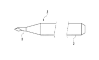
図1は、本発明のセンタードリルの実施形態としてのセンタードリル1の全体的な構成図である。
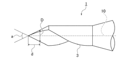
図2は、センタードリル1の切刃部3を特に示す図である。
FIG. 1 is an overall configuration diagram of a
FIG. 2 is a diagram particularly showing the
センタードリル1は、例えば、検査対象の加工精度を検査するための検査治具を被削材とする。センタードリル1は、別途のドリルが穴開け加工する被削材に対し、ドリル(ドリルの中心軸)の位置決めのためのガイド穴を形成する。センタードリル1は、本体2と、切刃部3と、を有する。
The
本体2は、円柱状の棒状部材であり、例えば直径が約3mmである。本体2は、ガイド穴の中心軸に略一致する方向に伸びる中心軸10を有する。
The
切刃部3は、本体2の一端に形成され、所定の先端角aで形成される。先端角aは、切刃部3の被削材に対する切込深さと、切り込んだ切刃部3が被削材に形成するガイド穴の直径(被削材表面の開口の直径であって、ガイド穴の最大直径)とを、略同一とする角度に設定されている。このような先端角aは、幾何学的に求められ、具体的には53.13度である。
The
すなわち、図2に示すように、被削材の表面から中心軸10方向に距離dだけ切り込んだ場合、被削材に形成されるガイド穴の直径、すなわち、被削材表面の同一面上に位置する切刃部3の断面の直径Dは、この距離dと略等しくなる。すなわち、例えば、切刃部3が0.5mm進入した場合、ガイド穴21の最大直径は、0.5mmとなる。
That is, as shown in FIG. 2, when a distance d is cut from the surface of the work material in the
ここで、別途のドリルが被削材に穴を形成する際、ドリルの直径に対応する直径(チゼルエッジの長さ)に対応するガイド穴が形成されていることが好ましい。 Here, when a separate drill forms a hole in the work material, it is preferable that a guide hole corresponding to the diameter corresponding to the diameter of the drill (the length of the chisel edge) is formed.
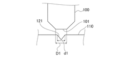
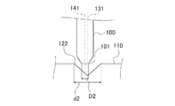
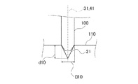
すなわち、図3に示すように、ドリル100の先端101の長さD1(チゼルエッジの長さ)に対して小さい直径d1を有するガイド穴121が形成されると、先端101がガイド穴121に嵌まり合うことができない。この場合、先端101が被削材110に対して滑ったり、ドリル100の中心軸がガイド穴121の中心軸に対して湾曲したりする虞がある。一方、図4に示すように、ドリル100の先端101の長さD2(ドリル100の直径)に対して大きい直径d2を有するガイド穴122が形成されると、ガイド穴122の中心軸131とドリル100の中心軸141とが一致せず、位置決め精度が得られない虞がある。
That is, as shown in FIG. 3, when the
以上から、ガイド穴は、ドリルの径などに対応する径を有することが好ましい。例えば、ドリルに応じて直径の異なるセンタードリル1を用いてガイド穴を形成することが考えられる。しかし、センタードリル1の交換作業が都度生じてしまい、作業効率が低下してしまう。また、センタードリル1の切込深さを計測することにより、切刃部3の形状から幾何学的にガイド穴の直径を算出することも考えられる。例えば先端角が60度のセンタードリルの場合、直径1mmのガイド穴21を開けようとすると、√3/2mm分だけ切り込めばよい。しかしながら、得たい直径に対する切込深さを毎回算出する必要があり、加工現場においては作業を複雑化してしまう。
From the above, it is preferable that the guide hole has a diameter corresponding to the diameter of the drill or the like. For example, it is conceivable to form a guide hole by using a
これに対し、本実施形態におけるセンタードリル1は、ガイド穴に形成する直径の制御に、好適に用いることができる。すなわち、センタードリル1は、図5に示すように、切込深さd10とガイド穴21の被削材110と同一面上における直径D10とが略一致する。このため、センタードリル1は、ドリル100の直径に応じて、得たいガイド穴21の直径に相当する切込深さ分だけ被削材に切り込めばよい。すなわち、切込深さを計測して切り込みさえすれば、直ちに得たい直径のガイド穴21を得ることができる。これにより、ガイド穴21の中心軸31と、ドリル100の中心軸41とを一致させることができ、高い位置決め精度を得ることができる。
On the other hand, the
なお、先端角aは、加工される穴の公差などに起因する誤差が許容されるため、完全に53.13度に一致している必要はない。例えば、先端角aは、±0.1度の誤差が許容され得る。 It should be noted that the tip angle a does not have to completely match 53.13 degrees because an error due to the tolerance of the hole to be machined or the like is allowed. For example, the tip angle a can tolerate an error of ± 0.1 degrees.
本発明のいくつかの実施形態を説明したが、これらの実施形態は、例として提示したものであり、発明の範囲を限定することは意図していない。これら新規な実施形態は、その他の様々な形態で実施されることが可能であり、発明の要旨を逸脱しない範囲で、種々の省略、置き換え、変更を行うことができる。これら実施形態やその変形は、発明の範囲や要旨に含まれるとともに、特許請求の範囲に記載された発明とその均等の範囲に含まれる。 Although some embodiments of the present invention have been described, these embodiments are presented as examples and are not intended to limit the scope of the invention. These novel embodiments can be implemented in various other embodiments, and various omissions, replacements, and changes can be made without departing from the gist of the invention. These embodiments and modifications thereof are included in the scope and gist of the invention, and are included in the scope of the invention described in the claims and the equivalent scope thereof.
1 センタードリル
2 本体
3 切刃部
10、131、141 中心軸
21、121、122 ガイド穴
100 ドリル
101 先端
110 被削材
a 先端角
1
Claims (3)
前記ガイド穴の中心軸に略一致する方向に伸びる中心軸を有する本体と、
前記本体の一端に形成され所定の先端角で形成された切刃部と、を備え、
前記先端角は、前記本体の前記中心軸に直交する前記被削材の表面に対して前記切刃部が距離d進入した場合、前記被削材の表面の同一面上に位置する前記切刃部の断面の直径Dと、前記距離dとを、同一とする角度である、センタードリル。 A drill for drilling a work material is a center drill for forming a guide hole for positioning with respect to the work material.
A main body having a central axis extending in a direction substantially matching the central axis of the guide hole,
A cutting edge portion formed at one end of the main body and formed at a predetermined tip angle is provided.
The tip angle is such that the cutting edge is located on the same surface of the surface of the work material when the cutting edge portion enters the surface of the work material orthogonal to the central axis of the main body by a distance d. the diameter D of the cross section of the part, and the distance d, the angle of the same, the center drill.
Priority Applications (1)
| Application Number | Priority Date | Filing Date | Title |
|---|---|---|---|
| JP2020106948A JP6861448B1 (en) | 2020-06-22 | 2020-06-22 | Center drill |
Applications Claiming Priority (1)
| Application Number | Priority Date | Filing Date | Title |
|---|---|---|---|
| JP2020106948A JP6861448B1 (en) | 2020-06-22 | 2020-06-22 | Center drill |
Publications (2)
| Publication Number | Publication Date |
|---|---|
| JP6861448B1 true JP6861448B1 (en) | 2021-04-21 |
| JP2022001394A JP2022001394A (en) | 2022-01-06 |
Family
ID=75521014
Family Applications (1)
| Application Number | Title | Priority Date | Filing Date |
|---|---|---|---|
| JP2020106948A Active JP6861448B1 (en) | 2020-06-22 | 2020-06-22 | Center drill |
Country Status (1)
| Country | Link |
|---|---|
| JP (1) | JP6861448B1 (en) |
Family Cites Families (5)
| Publication number | Priority date | Publication date | Assignee | Title |
|---|---|---|---|---|
| NL189365C (en) * | 1984-04-09 | 1993-03-16 | Fundex Naamloze Vennootschap | GROUND REPLACEMENT DRILL AND METHOD FOR FORMING A FOUNDATION POLE IN THE GROUND USING THAT GROUND REPLACEMENT DRILL. |
| JPH09253913A (en) * | 1996-03-22 | 1997-09-30 | Unisia Jecs Corp | Processing method of hole |
| JP4206778B2 (en) * | 2002-02-27 | 2009-01-14 | 三菱マテリアル株式会社 | Center drill |
| US7540696B1 (en) * | 2004-01-15 | 2009-06-02 | Century Tool & Design, Inc. | Spot drilling insert |
| JP2006231430A (en) * | 2005-02-22 | 2006-09-07 | Tungaloy Corp | Centering drill and machining method using the same |
-
2020
- 2020-06-22 JP JP2020106948A patent/JP6861448B1/en active Active
Also Published As
| Publication number | Publication date |
|---|---|
| JP2022001394A (en) | 2022-01-06 |
Similar Documents
| Publication | Publication Date | Title |
|---|---|---|
| US8192114B2 (en) | Combination of center drill and drill holding tool | |
| EP1319466A2 (en) | System of laser positioning of an aperture processing machine | |
| US10150168B2 (en) | Drill | |
| JP2008207327A (en) | Method and apparatus to secure component in position for fabrication | |
| US20080115860A1 (en) | Adjustable Guidebushes | |
| JP6861448B1 (en) | Center drill | |
| US3743433A (en) | Drill jig apparatus | |
| JPWO2017034032A1 (en) | 3-flute drill | |
| JPWO2007097474A1 (en) | Non-axisymmetric blade drill | |
| KR101032667B1 (en) | Center drill | |
| JP6751571B2 (en) | Hole drilling method using an end mill | |
| EP3130421B1 (en) | Apparatus for hole repair comprising a bottom cutting step up reamer | |
| JP2008049434A (en) | Cutting tool | |
| JP2000176714A (en) | Boring method | |
| JP4426407B2 (en) | Cutting device | |
| AU2018101473A4 (en) | Improvements relating to cutting devices to make internal keyways, splines and other shapes in blind bores and through bores | |
| JP2002521223A (en) | Drill bit for shallow holes | |
| US20070231090A1 (en) | Hole Saw Alignment Rod and Method of Using Same | |
| KR101907557B1 (en) | Air Coolant Hole Machining Jig For Gas Turbine, and Hole Machining Method Using The Same | |
| JP2007245295A (en) | Insert detachable-type drill | |
| KR101095245B1 (en) | Right angle drlling tool and right angle driiling method using it | |
| JP2014200898A (en) | Cutting insert and drill head | |
| RU2176176C2 (en) | Method of drilling deep openings of small diameter, and bladed drill of one-way cutting | |
| JP2010036295A (en) | Drill and method for manufacturing same | |
| JP2005103706A (en) | Cutting tool |
Legal Events
| Date | Code | Title | Description |
|---|---|---|---|
| A621 | Written request for application examination |
Free format text: JAPANESE INTERMEDIATE CODE: A621 Effective date: 20200622 |
|
| A871 | Explanation of circumstances concerning accelerated examination |
Free format text: JAPANESE INTERMEDIATE CODE: A871 Effective date: 20200622 |
|
| A975 | Report on accelerated examination |
Free format text: JAPANESE INTERMEDIATE CODE: A971005 Effective date: 20200722 |
|
| A131 | Notification of reasons for refusal |
Free format text: JAPANESE INTERMEDIATE CODE: A131 Effective date: 20201006 |
|
| A601 | Written request for extension of time |
Free format text: JAPANESE INTERMEDIATE CODE: A601 Effective date: 20201204 |
|
| A521 | Request for written amendment filed |
Free format text: JAPANESE INTERMEDIATE CODE: A523 Effective date: 20201223 |
|
| TRDD | Decision of grant or rejection written | ||
| A01 | Written decision to grant a patent or to grant a registration (utility model) |
Free format text: JAPANESE INTERMEDIATE CODE: A01 Effective date: 20210316 |
|
| A61 | First payment of annual fees (during grant procedure) |
Free format text: JAPANESE INTERMEDIATE CODE: A61 Effective date: 20210323 |
|
| R150 | Certificate of patent or registration of utility model |
Ref document number: 6861448 Country of ref document: JP Free format text: JAPANESE INTERMEDIATE CODE: R150 |
|
| R250 | Receipt of annual fees |
Free format text: JAPANESE INTERMEDIATE CODE: R250 |