JP6861447B2 - Electronic component mounting machine and electronic component mounting method - Google Patents
Electronic component mounting machine and electronic component mounting method Download PDFInfo
- Publication number
- JP6861447B2 JP6861447B2 JP2020051956A JP2020051956A JP6861447B2 JP 6861447 B2 JP6861447 B2 JP 6861447B2 JP 2020051956 A JP2020051956 A JP 2020051956A JP 2020051956 A JP2020051956 A JP 2020051956A JP 6861447 B2 JP6861447 B2 JP 6861447B2
- Authority
- JP
- Japan
- Prior art keywords
- electronic components
- tape material
- component mounting
- electronic component
- mounting machine
- Prior art date
- Legal status (The legal status is an assumption and is not a legal conclusion. Google has not performed a legal analysis and makes no representation as to the accuracy of the status listed.)
- Active
Links
- 238000000034 method Methods 0.000 title claims description 16
- 239000000463 material Substances 0.000 claims description 76
- 238000001514 detection method Methods 0.000 claims description 73
- 238000000605 extraction Methods 0.000 claims 1
- 230000007257 malfunction Effects 0.000 description 5
- 239000002390 adhesive tape Substances 0.000 description 2
- 238000012986 modification Methods 0.000 description 2
- 230000004048 modification Effects 0.000 description 2
- 230000003287 optical effect Effects 0.000 description 2
- 208000032368 Device malfunction Diseases 0.000 description 1
- 238000010586 diagram Methods 0.000 description 1
- 239000004973 liquid crystal related substance Substances 0.000 description 1
- 238000004519 manufacturing process Methods 0.000 description 1
- 238000011144 upstream manufacturing Methods 0.000 description 1
Images
Landscapes
- Supply And Installment Of Electrical Components (AREA)
Description
ここで開示する技術は、回路基板に電子部品を装着する電子部品実装機に関する。 The technique disclosed here relates to an electronic component mounting machine that mounts electronic components on a circuit board.
特開2005−116599号公報に、電子部品実装機(以下、実装機とも称する)が開示されている。この実装機は、テープ材を装着ヘッドに対して送り出すテープフィーダと、テープ材に残存する電子部品の数を計数する計数装置と、テープ材の終端に新たなテープ材の始端を繋ぎ合わせたスプライス部を検出する検出装置を備えている。計数装置は、検出装置がスプライス部を検出したときに、計数値をリセットするように構成されている。 Japanese Patent Application Laid-Open No. 2005-116599 discloses an electronic component mounting machine (hereinafter, also referred to as a mounting machine). This mounting machine has a tape feeder that sends the tape material to the mounting head, a counting device that counts the number of electronic components remaining on the tape material, and a splice that connects the end of the tape material to the start of a new tape material. It is equipped with a detection device that detects the unit. The counting device is configured to reset the counting value when the detecting device detects the splice portion.
上記した実装機によると、検出装置がスプライス部を検出したときに、計数値をリセットすることによって、これまでに生じた計数値の誤差を取り除くことができる。しかしながら、検出装置の信頼性には限界があり、検出装置がスプライス部ではない部分をスプライス部として検出することも起こり得る。このような場合に、計数装置が計数値をリセットしてしまうと、その後の計数装置による計数値には許容できない誤差が生じてしまう。 According to the above-mentioned mounting machine, when the detection device detects the splice portion, the counting value can be reset to remove the error of the counting value that has occurred so far. However, the reliability of the detection device is limited, and it is possible that the detection device detects a portion other than the splice portion as a splice portion. In such a case, if the counting device resets the counting value, an unacceptable error will occur in the counting value by the counting device thereafter.
本明細書は、上記の問題を解決又は少なくとも低減し得る技術を提供する。 The present specification provides techniques that can solve or at least reduce the above problems.
検出装置がスプライス部を検出したときに、計数装置による計数値が十分に小さな値になっていれば、実際のスプライス部が正しく検出されたと判断することができる。それに対して、計数値が未だに大きな値であるときは、スプライス部ではない部分がスプライス部として検出されるなど、検出装置が誤作動したものと推定することができる。このように、検出装置がスプライス部を検出したときに、計数装置による計数値を参照することによって、検出装置が実際のスプライシング部を正しく検出したのか否かを判別することができる。 When the detection device detects the splice unit, if the value counted by the counting device is sufficiently small, it can be determined that the actual splice unit has been detected correctly. On the other hand, when the count value is still large, it can be estimated that the detection device has malfunctioned, for example, a portion other than the splice portion is detected as a splice portion. In this way, when the detection device detects the splice unit, it is possible to determine whether or not the detection device has correctly detected the actual splicing unit by referring to the count value by the counting device.
上記した知見に基づいて、電子部品実装機が開示される。この電子部品実装機は、回路基板に電子部品を装着する装着ヘッドと、複数の電子部品を収容する第1のテープ材を装着ヘッドに対して送り出すテープフィーダと、第1のテープ材が収容する電子部品数の初期値から、電子部品実装機の動作量に応じた消費数を減算することによって、第1のテープ材に残存する電子部品数を計数する計数装置と、第1のテープ材の終端に第2のテープ材の始端を繋ぎ合わせたスプライス部を検出する検出装置と、検出装置がスプライス部を検出したときに、計数装置による計数値が所定の正常範囲内にあるのか否かを判定する判定装置とを備える。 Based on the above findings, the electronic component mounting machine will be disclosed. This electronic component mounting machine accommodates a mounting head for mounting electronic components on a circuit board, a tape feeder for feeding a first tape material for accommodating a plurality of electronic components to the mounting head, and a first tape material. A counting device that counts the number of electronic components remaining in the first tape material by subtracting the number of consumption according to the operating amount of the electronic component mounting machine from the initial value of the number of electronic components, and the first tape material. A detection device that detects the splice portion by connecting the start end of the second tape material to the end, and whether or not the count value by the counting device is within a predetermined normal range when the detection device detects the splice portion. A determination device for determining is provided.
上記した構成によれば、検出装置がスプライス部を検出したときに、計数装置による計数値を参照することによって、検出装置による検出の適否を判別することができる。これにより、例えば検出装置の誤作動によって、計数装置による計数値が不適切にリセット又は補正されることを避けることができる。 According to the above configuration, when the detection device detects the splice portion, it is possible to determine the appropriateness of the detection by the detection device by referring to the count value by the counting device. As a result, it is possible to prevent the counting value by the counting device from being improperly reset or corrected due to, for example, a malfunction of the detection device.
本技術の一実施形態において、判定装置は、第1のテープ材が収容する電子部品数の初期値に応じて、前記した正常範囲を変更することが好ましい。このような構成によると、電子部品数の初期値が異なる様々な第1のテープ材に応じて、検出装置による検出の適否を正しく判別することができる。 In one embodiment of the present technology, it is preferable that the determination device changes the above-mentioned normal range according to the initial value of the number of electronic components accommodated in the first tape material. According to such a configuration, it is possible to correctly determine the appropriateness of detection by the detection device according to various first tape materials having different initial values of the number of electronic components.
上記した実施形態において、判定装置は、第1のテープ材が収容する電子部品数の初期値に所定の係数を乗じることによって、前記した正常範囲を規定する上限又は下限の少なくとも一方を決定してもよい。あるいは、判定装置は、当該初期値から所定の数を減算することによって、当該正常範囲を規定する上限又は下限の少なくとも一方を決定してもよい。いずれの手法によっても、判定装置は、第1のテープ材が収容する電子部品数の初期値に応じて、計数装置による計数値の判定に用いる正常範囲を変更することができる。 In the above-described embodiment, the determination device determines at least one of the upper limit and the lower limit that defines the above-mentioned normal range by multiplying the initial value of the number of electronic components accommodated by the first tape material by a predetermined coefficient. May be good. Alternatively, the determination device may determine at least one of the upper limit and the lower limit that defines the normal range by subtracting a predetermined number from the initial value. By either method, the determination device can change the normal range used for determining the counting value by the counting device according to the initial value of the number of electronic components accommodated in the first tape material.
本技術の一実施形態において、電子部品実装機は、計数装置による計数値が正常範囲外にあるときに、所定の報知動作を実行する報知装置をさらに備えることが好ましい。このような構成によると、電子部品実装機は、検出装置が誤作動したときに、そのことを例えば作業者やその他の装置に知らせることができる。 In one embodiment of the present technology, it is preferable that the electronic component mounting machine further includes a notification device that executes a predetermined notification operation when the count value by the counting device is out of the normal range. According to such a configuration, the electronic component mounting machine can notify, for example, an operator or other device when the detection device malfunctions.
上記した実施形態において、報知装置は、前記した報知動作として、音、光、振動、電気信号、電波のなかの少なくとも一つを外部に発することが好ましい。具体例として、報知装置は、所定の警告音を発する、所定の警告灯を点灯する、液晶パネル等の光学的ディスプレイに所定の表示を行う、有線又は無線で外部の装置に所定の警告信号を送信する、ものであってよい。 In the above-described embodiment, the notification device preferably emits at least one of sound, light, vibration, an electric signal, and a radio wave to the outside as the notification operation described above. As a specific example, the notification device emits a predetermined warning sound, turns on a predetermined warning light, displays a predetermined display on an optical display such as a liquid crystal panel, or sends a predetermined warning signal to an external device by wire or wirelessly. It may be something to send.
本技術の一実施形態において、電子部品実装機は、計数装置による計数値が正常範囲内にあるときに、計数装置による計数値を所定の正常値に補正する補正装置をさらに備えることが好ましい。このような構成によると、検出装置がスプライス部を正しく検出したときに、計数装置による計数値(これは誤差を含み得る)を、正しい値に補正することができる。 In one embodiment of the present technology, it is preferable that the electronic component mounting machine further includes a correction device that corrects the counting value by the counting device to a predetermined normal value when the counting value by the counting device is within the normal range. According to such a configuration, when the detection device correctly detects the splice portion, the counting value by the counting device (which may include an error) can be corrected to the correct value.
上記の実施形態において、正常値は、検出装置がスプライス部を検出したときに、第1のテープ材に残存することが予定される電子部品数とするとよい。なお、当該予定される電子部品数は、検出装置がスプライス部を検出する検出位置と、装着ヘッドが第1のテープ材から電子部品を取り上げる取上位置との間の距離に基づいて、予め決定することができる。 In the above embodiment, the normal value may be the number of electronic components that are expected to remain in the first tape material when the detection device detects the splice portion. The planned number of electronic components is determined in advance based on the distance between the detection position where the detection device detects the splice portion and the pick-up position where the mounting head picks up the electronic component from the first tape material. can do.
上記の実施形態において、正常値は、第1のテープ材が単位長さあたりに収容する電子部品数に応じて変更されることが好ましい。このような構成によると、補正装置は、各種の第1のテープに応じて、計数値の補正を正しく実行することができる。 In the above embodiment, the normal value is preferably changed according to the number of electronic components accommodated in the first tape material per unit length. According to such a configuration, the correction device can correctly correct the count value according to various first tapes.
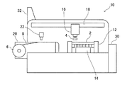
図面を参照して、実施例の電子部品実装機10(以下、実装機10とも称する)を説明する。図1に示すように、実装機10は、回路基板2に複数の電子部品4を装着する装置である。実装機10は、コンベア12と、支持装置14と、装着ヘッド16と、移動装置18と、複数のテープフィーダ20と、検出装置22と、制御装置30と、タッチパネル32とを備える。
The electronic component mounting machine 10 (hereinafter, also referred to as a mounting machine 10) of the embodiment will be described with reference to the drawings. As shown in FIG. 1, the
コンベア12は、回路基板2を実装機10に搬入するとともに、複数の電子部品4が装着された回路基板2を実装機10から搬出する装置である。支持装置14は、コンベア12が搬入した回路基板2を、所定の高さ位置で支持する装置である。装着ヘッド16は、テープフィーダ20から電子部品4を取り上げるとともに、その電子部品4を回路基板2上に装着する装置である。移動装置18は、テープフィーダ20及び支持装置14に対して、装着ヘッド16を移動させる装置である。
The
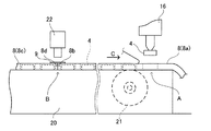
テープフィーダ20は、装着ヘッド16に電子部品4を供給する装置である。テープフィーダ20は、実装機10に対して着脱可能に構成されている。テープフィーダ20は、リール6に巻かれたテープ材8を、装着ヘッド16に対して送り出す。図2に示すように、テープ材8は、その長手方向に沿って、複数の電子部品4を等間隔で収容している。テープフィーダ20は、送り機構21によって、テープ材8を断続的に送り出す。それにより、各々の電子部品4が取上位置Aへ順次配置される。取上位置Aに配置された電子部品4は、装着ヘッド16によって取り上げられ、回路基板2へ装着される。
The
実装機10が動作を続けていくことで、リール6に巻かれていたテープ材8の残りが少なくなると、作業者によるスプライシング作業が行われる。図2に示すように、スプライシング作業とは、使用中のテープ材8a(以下、第1のテープ材8aという)の終端8bに、新たなテープ材8c(以下、第2のテープ材という)の始端8dを接続する作業である。一例ではあるが、二つのテープ材8a、8cは、例えば粘着性テープ9によって接続される。以下では、二つのテープ材8a、8cが互いに接続された部分をスプライス部と称する。
As the
検出装置22は、上述したスプライス部を検出するセンサである。検出装置22の具体的な構成は特に限定されない。一例として、検出装置22は、スプライス部の粘着性テープ9を検出する光学的なセンサとすることができる。図2に示すように、検出装置22がスプライス部を検出する検出位置Bは、テープ材8の送り方向Cに関して、電子部品4の取上位置Aよりも上流側に位置している。従って、スプライス部が検出装置22による検出位置をBに達した時点で、第1のテープ材8aには、取上位置Aから検出位置Bまでの距離に、第1のテープ材8aが単位長さあたりに収容する電子部品数を乗じた数の電子部品4が残存することが予定される。以下、この数を予定残存数と称する。
The
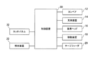
制御装置30は、実装機10の各部の動作を制御する装置である。制御装置30は、一又は複数のコンピュータによって構成することができる。図3に示すように、制御装置30は、コンベア12、支持装置14、装着ヘッド16、移動装置18、テープフィーダ20及びタッチパネル32と通信可能に接続されており、それらに各種の制御信号を出力することができる。また、制御装置30は、検出装置22と電気的に接続されており、検出装置22の検出結果(出力信号)を受信することができる。
The
タッチパネル32は、ユーザインターフェースの一種であり、作業者から各種の指示を受け付けるとともに、作業者に対して各種の情報を表示することができる。例えばタッチパネル32は、実装機10において各種のエラーが生じたときに、そのエラーを作業者に表示することができる。
The
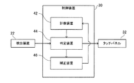
図4は、制御装置30の機能的な構成の一部を示すブロック図である。図4に示すように、制御装置30は、機能的に、計数装置42と判定装置44と補正装置46とを備える。これらの装置42、44、46は、制御装置30を構成するハードウエア及びソフトウエアによって構成することができ、必ずしも互いに独立した装置には限られない。即ち、これらの装置42、44、46の二以上が、共通のハードウエアによって構成されてもよい。
FIG. 4 is a block diagram showing a part of the functional configuration of the
計数装置42は、第1のテープ材8aに残存する電子部品数を計数する。計数装置42は、第1のテープ材8aが収容する電子部品数の初期値から、実装機10の動作量に応じた電子部品4の消費数を減算することによって、第1のテープ材8aに残存する電子部品数を計数する。なお、第1のテープ材8aが収容する電子部品数の初期値は、タッチパネル32を介して作業者によって教示されてもよいし、データサーバといった外部の装置から取得されてもよい。計数装置42は、教示又は取得された初期値を記憶することができる。また、上記した実装機10の動作量とは、例えば実装機10の動作回数であってもよいし、実装機10の動作時間であってもよい。
The
判定装置44は、検出装置22がスプライス部を検出したときに、計数装置42による計数値が所定の正常範囲内にあるのか否かを判定する。スプライス部が検出装置22による検出位置Bに達した時点で、第1のテープ材8aには、前述した予定残存数の電子部品4が残存するはずである。従って、検出装置22がスプライス部を正しく検出していれば、計数装置42による計数値は当該予定残存数に等しくなるか、それに近い値となる。なお、計数値が予定残存数に必ずしも一致しないのは、計数装置42による計数値にも避けられない誤差が生じ得るためである。それに対して、検出装置22がスプライス部を検出したときに、計数装置42による計数値が予定残存数から大きく相違していれば、検出装置22がスプライス部ではない部分をスプライス部として検出するなど、検出装置22が誤作動を起したものと推定することができる。従って、計数装置42による計数値が、所定の正常範囲内にあるのか否かを判定することで、検出装置22による検出が、スプライス部を正しく検出したものであるのか、誤作動によるものであるのかを判別することができる。
When the
上記した正常範囲は、適宜設定することができる。正常範囲は、固定された範囲であってもよいし、各種の第1のテープ材8aに応じて変更されてもよい。一例ではあるが、判定装置44は、第1のテープ材8aが収容する電子部品数の初期値に所定の係数を乗じることによって、正常範囲を規定する上限又は下限の少なくとも一方を決定してもよい。例えば、判定装置44は、下限値を0に固定した上で、上限値に関する係数を0.1としてもよい。この場合、初期値が10000個であるとすると、正常範囲の上限値は10000×0.1=1000個となり、0〜1000個の範囲が正常範囲となる。
The above-mentioned normal range can be set as appropriate. The normal range may be a fixed range or may be changed according to various
あるいは、判定装置44は、第1のテープ材8aが収容する電子部品数の初期値から所定の数を減算することによって、正常範囲を規定する上限又は下限の少なくとも一方を決定してもよい。例えば、下限値は0に固定した上で、上限値に関する減算値を9000とすることができる。この場合、初期値が10000個であるとすると、正常範囲の上限値は10000−9000=1000個となり、0〜1000個の範囲が正常範囲となる。
Alternatively, the
あるいは、判定装置44は、前述した予定残存数に応じて、正常範囲を変更することも有効である。例えば、判定装置44は、第1のテープ材8aの予定残存数に所定の係数を乗じることによって、正常範囲を規定する上限又は下限の少なくとも一方を決定することができる。また、判定装置44は、第1のテープ材8aの予定残存数に所定の数を加算又は減算することによって、正常範囲を規定する上限又は下限の少なくとも一方を決定することもできる。さらに、上記した所定の係数及び/又は所定の数は、第1のテープ材8aの態様や、第1のテープ材8aが収容する電子部品の種類に応じて、適宜変更されることも有効である。
Alternatively, it is also effective for the
計数装置42による計数値が前記した正常範囲外であると、判定装置44は、タッチパネル32を用いて報知動作を実行する。具体的には、判定装置44がタッチパネル32へ所定のエラー信号を出力し、エラー信号を受けたタッチパネル32が所定のエラー画面を表示する。それにより、検出装置22による誤作動が作業者に報知される。なお、実装機10は、タッチパネル32による表示に代えて、検出装置22が誤作動したことを示す音、その他の光、振動、電気信号、電波を外部に発してもよい。ここで、例えば検出装置22の誤作動が所定の頻度を超えて発生する場合、判定装置44は、実装機の生産動作を中止する処理を実行してもよい。
When the counting value by the
一方、計数装置42による計数値が前記した正常範囲内であれば、補正装置46が、計数装置42による計数値を補正する処理を実行する。補正装置46は、補正に用いる正常値として前述した予定残存数を記憶しており、計数装置42による計数値を当該正常値に書き換える。これにより、計数装置42による計数値に生じている誤差が排除される。前述したように、予定残存数は、検出装置22がスプライス部を検出したときに第1のテープ材8aに残存することが予定される電子部品数であって、第1のテープ材8aが単位長さあたりに収容する電子部品数に応じて変化する。従って、補正装置46は、第1のテープ材8aが単位長さあたりに収容する電子部品数に応じて、正常値を変更するとよい。この場合、第1のテープ材8aが単位長さあたりに収容する電子部品数は、作業者によって教示されてもよいし、データサーバといった外部の装置から教示されてもよい。なお、上述に限られず、補正装置46が用いる正常値は、適宜決定されるものであってもよい。
On the other hand, if the counting value by the
以上のように、本実施例の実装機10によると、検出装置22がスプライス部を検出したときに、計数装置42による計数値を参照することによって、検出装置22による検出の適否を判別することができる。これにより、例えば検出装置22が誤作動したときに、計数装置42による計数値が不適切に補正されることを避けることができる。
As described above, according to the mounting
以上、本発明の具体例を詳細に説明したが、これらは例示にすぎず、請求の範囲を限定するものではない。請求の範囲に記載の技術には、以上に例示した具体例を様々に変形、変更したものが含まれる。 Although specific examples of the present invention have been described in detail above, these are merely examples and do not limit the scope of claims. The techniques described in the claims include various modifications and modifications of the specific examples illustrated above.
例えば、検出装置22の位置は適宜変更可能であり、例えば、検出装置22が装着ヘッド16に配置されてもよい。このような構成によると、図2に示す取上位置Aと検出位置Bとを実質的に一致させることができる。この場合、検出装置22がスプライス部を検出した時点で、第1のテープ材8aに残存する電子部品数はゼロとなるので、第1のテープ材8aの態様にかかわらず、上述した補正装置46の正常値はゼロと設定することができる。
For example, the position of the
本明細書または図面に説明した技術要素は、単独であるいは各種の組み合わせによって技術的有用性を発揮するものであり、出願時の請求項に記載の組み合わせに限定されるものではない。また、本明細書または図面に例示した技術は複数目的を同時に達成するものであり、そのうちの一つの目的を達成すること自体で技術的有用性を持つものである。 The technical elements described herein or in the drawings exhibit their technical usefulness alone or in various combinations, and are not limited to the combinations described in the claims at the time of filing. In addition, the techniques illustrated in this specification or drawings achieve a plurality of objectives at the same time, and achieving one of the objectives itself has technical usefulness.
2:回路基板
4:電子部品
6:リール
8:テープ材
8a:第1のテープ材(使用中のテープ材)
8b:第1のテープ材の終端
8b:第2のテープ材(次のテープ材)
8d:第2のテープ材の始端
10:電子部品実装機
16:装着ヘッド
20:テープフィーダ
22:検出装置
30:制御装置
32:タッチパネル
42:計数装置
44:判定装置
46:補正装置
2: Circuit board 4: Electronic component 6: Reel 8:
8b: Termination of the
8d: Start end of second tape material 10: Electronic component mounting machine 16: Mounting head 20: Tape feeder 22: Detection device 30: Control device 32: Touch panel 42: Counting device 44: Judgment device 46: Correction device
Claims (7)
前記テープフィーダが送り出す第1のテープ材が収容する電子部品数の初期値から、前記電子部品実装機の動作量に応じた消費数を減算することによって、前記第1のテープ材に残存する電子部品数を計数する計数装置と、
前記第1のテープ材の終端に第2のテープ材の始端を繋ぎ合わせたスプライス部を検出位置において検出する検出装置と、
前記検出装置が前記スプライス部を検出したときに、前記計数装置による計数値が所定の正常範囲内にあるのか否かを判定する判定装置と、
前記計数装置による計数値が前記正常範囲内にあるときに、前記計数装置による計数値を所定の正常値に補正する補正装置と、
を備え、
前記正常値は、前記検出位置と前記取上位置との間の距離に基づいて予め決定された電子部品数である電子部品実装機。 It is an electronic component mounting machine that has a mounting head that mounts the electronic components picked up at the pick-up position from the tape feeder that sends out the tape material that accommodates multiple electronic components to the circuit board.
The electrons remaining in the first tape material are obtained by subtracting the consumption number according to the operating amount of the electronic component mounting machine from the initial value of the number of electronic components accommodated in the first tape material sent by the tape feeder. A counting device that counts the number of parts and
A detection device that detects at the detection position a splice portion in which the end of the first tape material and the start end of the second tape material are connected to each other.
When the detection device detects the splice portion, a determination device for determining whether or not the count value by the counting device is within a predetermined normal range, and a determination device.
A correction device that corrects the counting value by the counting device to a predetermined normal value when the counting value by the counting device is within the normal range.
Equipped with a,
The normal value is an electronic component mounting machine in which the number of electronic components is predetermined based on the distance between the detection position and the pick-up position.
前記テープフィーダが送り出す第1のテープ材が収容する電子部品数の初期値から、前記電子部品実装機の動作量に応じた消費数を減算することによって、前記第1のテープ材に残存する電子部品数を計数する計数装置と、The electrons remaining in the first tape material are obtained by subtracting the consumption number according to the operating amount of the electronic component mounting machine from the initial value of the number of electronic components accommodated in the first tape material sent by the tape feeder. A counting device that counts the number of parts and
前記第1のテープ材の終端に第2のテープ材の始端を繋ぎ合わせたスプライス部を検出位置において検出する検出装置と、A detection device that detects at the detection position a splice portion in which the end of the first tape material and the start end of the second tape material are connected to each other.
前記検出装置が前記スプライス部を検出したときに、前記計数装置による計数値が所定の正常範囲内にあるのか否かを判定する判定装置と、When the detection device detects the splice portion, a determination device for determining whether or not the count value by the counting device is within a predetermined normal range, and a determination device.
を備え、With
前記判定装置は、前記検出位置と前記取上位置との間の距離に基づいて予め決定された電子部品数に応じて前記正常範囲を変更する電子部品実装機。The determination device is an electronic component mounting machine that changes the normal range according to a predetermined number of electronic components based on a distance between the detection position and the pick-up position.
複数の電子部品を収容する第1のテープ材を、装着ヘッドが電子部品を取り上げる位置である取上位置へ送り出す送り出し工程と、 A delivery process in which the first tape material accommodating a plurality of electronic components is sent to a pick-up position where the mounting head picks up the electronic components.
前記第1のテープ材が収容する電子部品数の初期値から、前記電子部品実装機の動作量に応じた消費数を減算することによって、前記第1のテープ材に残存する電子部品数を計数する計数工程と、 The number of electronic components remaining in the first tape material is counted by subtracting the number of electronic components consumed according to the operating amount of the electronic component mounting machine from the initial value of the number of electronic components accommodated in the first tape material. Counting process and
前記第1のテープ材の終端に第2のテープ材の始端を繋ぎ合わせたスプライス部を検出位置において検出する検出工程と、 A detection step of detecting at a detection position a splice portion in which the end of the first tape material and the start end of the second tape material are connected to each other.
前記検出工程において前記スプライス部を検出したときに、前記計数工程において計数された計数値が所定の正常範囲内にあるのか否かを判定する判定工程と、 A determination step of determining whether or not the count value counted in the counting step is within a predetermined normal range when the splice portion is detected in the detection step.
前記計数値が前記正常範囲内にあるときに、前記検出位置と前記取出位置との間の距離に基づいて予め決定された電子部品数である正常値に、前記計数値を補正する補正工程と、 When the count value is within the normal range, a correction step of correcting the count value to a normal value, which is a predetermined number of electronic components based on the distance between the detection position and the take-out position. ,
を含む電子部品実装方法。 Electronic component mounting method including.
複数の電子部品を収容する第1のテープ材を、装着ヘッドが電子部品を取り上げる位置である取上位置へ送り出す送り出し工程と、 A delivery process in which the first tape material accommodating a plurality of electronic components is sent to a pick-up position where the mounting head picks up the electronic components.
前記第1のテープ材が収容する電子部品数の初期値から、前記電子部品実装機の動作量に応じた消費数を減算することによって、前記第1のテープ材に残存する電子部品数を計数する計数工程と、 The number of electronic components remaining in the first tape material is counted by subtracting the number of electronic components consumed according to the operating amount of the electronic component mounting machine from the initial value of the number of electronic components accommodated in the first tape material. Counting process and
前記第1のテープ材の終端に第2のテープ材の始端を繋ぎ合わせたスプライス部を検出位置において検出する検出工程と、 A detection step of detecting at a detection position a splice portion in which the end of the first tape material and the start end of the second tape material are connected to each other.
前記検出工程において前記スプライス部を検出したときに、前記計数工程において計数された計数値が、所定の正常範囲内にあるのか否かを判定する判定工程と、 A determination step of determining whether or not the count value counted in the counting step is within a predetermined normal range when the splice portion is detected in the detection step.
前記判定工程の判定に用いられる前記正常範囲を、前記検出位置と前記取出位置との間の距離に基づいて予め決定された電子部品数に応じて変更する変更工程と、 A changing step of changing the normal range used for determining the determination step according to a predetermined number of electronic components based on the distance between the detection position and the extraction position.
を含む電子部品実装方法。 Electronic component mounting method including.
Priority Applications (1)
| Application Number | Priority Date | Filing Date | Title |
|---|---|---|---|
| JP2020051956A JP6861447B2 (en) | 2020-03-24 | 2020-03-24 | Electronic component mounting machine and electronic component mounting method |
Applications Claiming Priority (1)
| Application Number | Priority Date | Filing Date | Title |
|---|---|---|---|
| JP2020051956A JP6861447B2 (en) | 2020-03-24 | 2020-03-24 | Electronic component mounting machine and electronic component mounting method |
Related Parent Applications (1)
| Application Number | Title | Priority Date | Filing Date |
|---|---|---|---|
| JP2015174265A Division JP6684016B2 (en) | 2015-09-04 | 2015-09-04 | Electronic component mounter |
Publications (2)
| Publication Number | Publication Date |
|---|---|
| JP2020107906A JP2020107906A (en) | 2020-07-09 |
| JP6861447B2 true JP6861447B2 (en) | 2021-04-21 |
Family
ID=71449501
Family Applications (1)
| Application Number | Title | Priority Date | Filing Date |
|---|---|---|---|
| JP2020051956A Active JP6861447B2 (en) | 2020-03-24 | 2020-03-24 | Electronic component mounting machine and electronic component mounting method |
Country Status (1)
| Country | Link |
|---|---|
| JP (1) | JP6861447B2 (en) |
Family Cites Families (1)
| Publication number | Priority date | Publication date | Assignee | Title |
|---|---|---|---|---|
| WO2016002029A1 (en) * | 2014-07-02 | 2016-01-07 | 富士機械製造株式会社 | Electronic-component mounter |
-
2020
- 2020-03-24 JP JP2020051956A patent/JP6861447B2/en active Active
Also Published As
| Publication number | Publication date |
|---|---|
| JP2020107906A (en) | 2020-07-09 |
Similar Documents
| Publication | Publication Date | Title |
|---|---|---|
| JP6348591B2 (en) | Electronic component mounting machine | |
| US10058020B2 (en) | Electronic component mounting system | |
| JP2014110322A (en) | Carrier tape set correct/incorrect determination system and carrier tape set correct/incorrect determination method in electronic component part mounting apparatus | |
| WO2012172715A1 (en) | Set-up method, component mounting method, and component mounting system | |
| JP5358494B2 (en) | Substrate transfer device, substrate transfer method, and surface mounter | |
| US7054707B2 (en) | Electronic component mounting system and electronic component mounting method | |
| JP6861447B2 (en) | Electronic component mounting machine and electronic component mounting method | |
| JP4074147B2 (en) | Parts feeder and component mounting equipment | |
| JP5100684B2 (en) | Management method in electronic component mounting apparatus management system | |
| US10667446B2 (en) | Component pickup rate calculating system for a component mounter | |
| JP6620306B2 (en) | Component mounting method and component mounting apparatus | |
| CN111034385B (en) | Manufacturing system and control method of manufacturing system | |
| JP6684016B2 (en) | Electronic component mounter | |
| JP3860512B2 (en) | Component supply feeder, component mounting apparatus, component mounting system, and mounting confirmation method | |
| JP5342374B2 (en) | Electronic component mounting device | |
| US11494278B2 (en) | Service system and server | |
| JP7345130B2 (en) | Component tape management device, component tape management system, and component tape management method | |
| JP7223136B2 (en) | Component mounter | |
| JP6698319B2 (en) | Parts supply feeder | |
| JP5452444B2 (en) | Electronic component mounting method and electronic component mounting apparatus | |
| WO2017145625A1 (en) | Inventory management apparatus, inventory management system, inventory management method, and program | |
| JP4340607B2 (en) | Control device used for mounting maintenance | |
| JP3078648B2 (en) | Component mounting method | |
| JP7531152B2 (en) | Method and component mounting device | |
| JP2019096803A (en) | Component recognition device and component mounting device |
Legal Events
| Date | Code | Title | Description |
|---|---|---|---|
| A521 | Request for written amendment filed |
Free format text: JAPANESE INTERMEDIATE CODE: A523 Effective date: 20200414 |
|
| A621 | Written request for application examination |
Free format text: JAPANESE INTERMEDIATE CODE: A621 Effective date: 20200414 |
|
| A521 | Request for written amendment filed |
Free format text: JAPANESE INTERMEDIATE CODE: A523 Effective date: 20200407 |
|
| A977 | Report on retrieval |
Free format text: JAPANESE INTERMEDIATE CODE: A971007 Effective date: 20210212 |
|
| TRDD | Decision of grant or rejection written | ||
| A01 | Written decision to grant a patent or to grant a registration (utility model) |
Free format text: JAPANESE INTERMEDIATE CODE: A01 Effective date: 20210302 |
|
| A61 | First payment of annual fees (during grant procedure) |
Free format text: JAPANESE INTERMEDIATE CODE: A61 Effective date: 20210323 |
|
| R150 | Certificate of patent or registration of utility model |
Ref document number: 6861447 Country of ref document: JP Free format text: JAPANESE INTERMEDIATE CODE: R150 |
|
| R250 | Receipt of annual fees |
Free format text: JAPANESE INTERMEDIATE CODE: R250 |
|
| R250 | Receipt of annual fees |
Free format text: JAPANESE INTERMEDIATE CODE: R250 |