JP6861416B2 - Chlorine dioxide gas concentration measuring instrument - Google Patents
Chlorine dioxide gas concentration measuring instrument Download PDFInfo
- Publication number
- JP6861416B2 JP6861416B2 JP2017204641A JP2017204641A JP6861416B2 JP 6861416 B2 JP6861416 B2 JP 6861416B2 JP 2017204641 A JP2017204641 A JP 2017204641A JP 2017204641 A JP2017204641 A JP 2017204641A JP 6861416 B2 JP6861416 B2 JP 6861416B2
- Authority
- JP
- Japan
- Prior art keywords
- electrode
- gas
- chlorine dioxide
- electrolytic solution
- current
- Prior art date
- Legal status (The legal status is an assumption and is not a legal conclusion. Google has not performed a legal analysis and makes no representation as to the accuracy of the status listed.)
- Active
Links
Images


Landscapes
- Electrolytic Production Of Non-Metals, Compounds, Apparatuses Therefor (AREA)
Description
本発明は、 空気中の含まれる二酸化塩素ガスの濃度測定器に係り、更に詳細には、2電極式定電位電解方式の二酸化塩素ガスの濃度測定器に関する。 The present invention relates to a chlorine dioxide gas concentration measuring device contained in air, and more particularly to a two-electrode constant potential electrolysis type chlorine dioxide gas concentration measuring device.
二酸化塩素ガス(ClO2)は強力な酸化剤であり、例えば、室内空気環境において、悪臭成分の分解・消臭や、室内に浮遊して空気感染する虞のあるウイルスや細菌の除去・殺菌などに使用されている。 Chlorine dioxide gas (ClO 2 ) is a powerful oxidizing agent. For example, in an indoor air environment, it decomposes and deodorizes malodorous components, and removes and sterilizes viruses and bacteria that may float in the room and infect the air. Is used for.
二酸化塩素ガスの化学的性質、生物化学的性質、および安全性についての知見は少ないが、米国労働安全衛生局(U.S. OSHA)は、労働安全衛生の観点から二酸化塩素の吸入暴露について、許容暴露濃度を8時間加重平均値(PEL−TWA)で0.1ppmの基準を設定している。
また、世界保健機関(WHO)も、0.1ppmが職場で二酸化塩素に暴露されている作業員の気道や眼の刺激を懸念する必要のない数値であるとしている。
Although little is known about the chemistry, biochemical properties, and safety of chlorine dioxide gas, the US Occupational Safety and Health Administration (US OSHA) has stated that inhalation exposure to chlorine dioxide from an occupational health and safety perspective. A standard of 0.1 ppm is set for the allowable exposure concentration as an 8-hour weighted average value (PEL-TWA).
The World Health Organization (WHO) also states that 0.1 ppm is a value that does not require concern for airway and eye irritation of workers exposed to chlorine dioxide in the workplace.
日本においては、二酸化塩素工業会が、安全幅を設けて室内濃度指針値を0.01ppm(自主基準)に定め、新しい知見が得られた際にはその結果に基づき変更するとしており、室内空気環境中の二酸化塩素ガスの濃度を測定し把握する必要がある。 In Japan, the Chlorine Dioxide Industry Association has set a safety margin and set the indoor concentration guideline value to 0.01 ppm (voluntary standard), and when new findings are obtained, it will be changed based on the results. It is necessary to measure and understand the concentration of chlorine dioxide gas in the environment.
室内空気環境中の二酸化塩素ガス濃度を測定する方法としては、ヨウ素溶液を使用するガス吸収法や、酸化還元反応を利用した電解式センサを使用する方法などを挙げることができる。 Examples of the method for measuring the chlorine dioxide gas concentration in the indoor air environment include a gas absorption method using an iodine solution and a method using an electrolytic sensor using a redox reaction.
上記ガス吸収法は、二酸化塩素ガスと、ヨウ素溶液中のヨウ化物とが反応することによってヨウ素が遊離し、このヨウ素をヨウ素滴定法や比色法等により分析することによって、二酸化塩素ガスの濃度を測定するものであり、低濃度の二酸化塩素ガスをヨウ素溶液に吸収させるために長時間を要し、かつ測定者の実験技術・知識の違いに基づく不確定要因を生じる。 In the above gas absorption method, iodine is liberated by reacting chlorine dioxide gas with iodide in an iodine solution, and the iodine is analyzed by an iodine titration method, a colorimetric method, or the like to obtain a concentration of chlorine dioxide gas. It takes a long time to absorb the low-concentration chlorine dioxide gas into the iodine solution, and uncertain factors are generated based on the difference in the experimental technique and knowledge of the measurer.
電解式センサを使用する方法は、電解質溶液(以下、電解液ということがある。)に電極を浸した構造で、ガス透過膜により電解液中に気相中の二酸化塩素ガスを取り込み、二酸化塩素に電気化学反応を起こさせて、作用電極に流れる電解電流を測定する方法である。 The method of using an electrolytic sensor is a structure in which an electrode is immersed in an electrolyte solution (hereinafter, may be referred to as an electrolytic solution), and chlorine dioxide gas in the gas phase is taken into the electrolytic solution by a gas permeable film to obtain chlorine dioxide. This is a method of measuring the electrolytic current flowing through the working electrode by causing an electrochemical reaction in the body.
例えば、特許文献1 、2には、作用電極と対極の2電極を定電圧に保って、流れる電流値を計測する2電極・定電圧方式の装置が開示されている。
しかし、上記2電極・定電圧方式は、制御回路を簡素化できる一方で、電位の基準となる参照電極を持たないため、結果として設定電位が一定しないという不可避的な問題がある。
For example,
However, while the above-mentioned two-electrode / constant voltage method can simplify the control circuit, it does not have a reference electrode as a reference for the potential, and as a result, there is an unavoidable problem that the set potential is not constant.
そのため、例えば、特許文献3、4には、基準となる電位を発生する参照電極を用いて、参照電極に対する作用電極の電位を所定の電位に制御して濃度測定を行う3電極定電位電解方式による装置が開示されている。
Therefore, for example, in
また、電解式センサを使用する方法は、センサを標準ガスで校正する必要があるが、二酸化塩素ガスは不安定で分解し易いため、標準ガスに塩素ガスを使用して二酸化塩素ガスに換算することが行われており、その換算係数は、pHや塩素ガスの発生条件等の影響を受けて変化するため測定誤差が生じ易い。
このため、従来の濃度測定装置では、製造会社などの専門業者に預けて校正を行う必要があり、ユーザーが校正することができず、実用性に劣る。
Also, in the method using an electrolytic sensor, it is necessary to calibrate the sensor with a standard gas, but since chlorine dioxide gas is unstable and easily decomposed, chlorine gas is used as the standard gas and converted to chlorine dioxide gas. This is done, and the conversion coefficient changes under the influence of pH, chlorine gas generation conditions, and the like, so measurement errors are likely to occur.
Therefore, in the conventional concentration measuring device, it is necessary to entrust the calibration to a specialized contractor such as a manufacturing company, and the user cannot calibrate the device, which is inferior in practicality.
しかしながら、特許文献3、4に記載の3電極定電位電解装置は、参照電極を通じて作用電極の電位を制御するフィードバック回路が必要である。
そして、フィードバック回路が入ると微量電流の制御は困難となり、参照電極を用いる3電極式電解回路では、電位制御の限界がμAオーダーと高くなることから、ppbオーダーの極低濃度の二酸化塩素ガスと測定するには、大面積の作用極が必要となって装置が大型になる。
また、大面積の作用極を用いた電極定電位電解装置では、高濃度の二酸化塩素を測定する場合に複雑化・性能低下・高価格化などの大きな問題を生じる。
However, the three-electrode constant potential electrolyzer described in
Then, when a feedback circuit is inserted, it becomes difficult to control a small amount of current, and in a three-electrode electrolytic circuit using a reference electrode, the limit of potential control becomes as high as μA order, so that the concentration of chlorine dioxide gas is extremely low on the order of ppb. A large working electrode is required for measurement, and the device becomes large.
In addition, an electrode constant potential electrolyzer using a large-area working electrode causes major problems such as complexity, performance deterioration, and high price when measuring high-concentration chlorine dioxide.
本発明は、このような従来技術の有する課題に鑑みてなされたものであり、その目的とするところは、極低濃度から高濃度までの二酸化塩素ガスを測定でき、かつコンパクトな2電極式の二酸化塩素濃度測定器を提供することにある。 The present invention has been made in view of the problems of the prior art, and an object of the present invention is a compact two-electrode type capable of measuring chlorine dioxide gas from an extremely low concentration to a high concentration. The purpose is to provide a chlorine dioxide concentration measuring device.
本発明者は、上記目的を達成すべく、二酸化塩素(ClO2)の電極反応を詳細に調べた結果、作用電極に二酸化塩素の電気化学的還元反応の電極反応が速い電極系を用い、対極が非分極界面とみなすことができる条件で電解すると、作用電極に二酸化塩素の還元電流のみが流れ、限界電流が一定(平坦)になる範囲が存在した。 As a result of investigating the electrode reaction of chlorine dioxide (ClO 2 ) in detail in order to achieve the above object, the present inventor uses an electrode system in which the electrode reaction of the electrochemical reduction reaction of chlorine dioxide is fast as a working electrode, and the opposite electrode. When electrolyzed under the condition that can be regarded as a non-polarized interface, only the reducing current of chlorine dioxide flows through the working electrode, and there is a range in which the critical current becomes constant (flat).
そして、定電位電源と見なすことができる所定の条件下で、限界電流が一定(平坦)な範囲内、すなわち、作用電極に二酸化塩素の還元電流のみが流れる電位で定電位電解すると、二酸化塩素の濃度と電流値とが、電位変動に関係なく広い電位範囲で厳密に比例関係を示し、電気回路全体が極めて単純な2電極式の定電位電解によって、安定かつ再現性良く二酸化塩素ガスの濃度を測定できることを見出し、本発明を完成するに至った。 Then, under a predetermined condition that can be regarded as a constant potential power source, constant potential electrolysis is performed within a constant (flat) range of the critical current, that is, at a potential at which only the reduction current of chlorine dioxide flows through the working electrode. The concentration and current value show a strict proportional relationship over a wide potential range regardless of potential fluctuations, and the concentration of chlorine dioxide gas can be stably and reproducibly achieved by two-electrode constant-potential electrolysis in which the entire electric circuit is extremely simple. We have found that it can be measured, and have completed the present invention.
即ち、上記課題は、以下の本発明の2電極式・定電位二酸化塩素濃度測定器により解決される。
(1)ガス透過膜を有する容器内に、電解液と対極と作用電極とを備えるセンサヘッド部と、
上記作用電極の電位を規制する定電圧電源部と、
上記作用電極を流れる電流値を検出する電流検出部と、を備える2電極式定電位電解二酸化塩素濃度測定器であって、
上記電解液が、塩化物イオン(Cl−)を含み、
上記対極が、上記電解液との接触面積が上記作用電極と上記電解液との接触面積の100倍以上である参照電極を兼ねたAgCl/Ag系の電極であり、
上記作用電極の電位を二酸化塩素の限界拡散電流の範囲内で一定に保ち、定電位電解することを特徴とする2電極式・定電位電解二酸化塩素濃度測定器。
(2)さらに、校正用標準ガス発生器を備え、
上記校正用標準ガス発生器が、
ガス通過性を有するガス発生電極と、
上記ガス発生電極と逆極性の対電極と、
上記両電極間に直流電流を印加する定電流電源部と、
NaClO2およびNaClを含む電解液と、
上記電解液を貯留する電解液槽と、
上記電解液槽からの電解液を上記ガス発生電極に導く電解液導通部材と、を備えるものであり、
上記対電極が上記電解液に接触する一方で、上記ガス発生電極の一方の面が上記電解液導通部材に導かれた電解液に接触し他方の面が気相に部分的に露出しており、
上記直流電流と、発生した二酸化塩素ガスを運ぶキャリアガスの流量とで二酸化塩素の濃度を制御することを特徴とする上記(1)に記載の2電極式・定電位電解二酸化塩素濃度測定器。
(3)上記定電流電源部が、電流波形を変更可能なプログラマブル電流規制電源であり、
上記電流波形が、通電初期に大電流を流した後に級数的に減少させ、その後一定であることを特徴とする上記(2)に記載の2電極式・定電位電解二酸化塩素濃度測定器。
That is, the above problem is solved by the following two-electrode type constant potential chlorine dioxide concentration measuring device of the present invention.
(1) A sensor head portion having an electrolytic solution, a counter electrode, and a working electrode in a container having a gas permeable membrane.
A constant voltage power supply that regulates the potential of the working electrode,
A two-electrode constant-potential electrolytic chlorine dioxide concentration measuring device including a current detection unit that detects a current value flowing through the working electrode.
The above electrolyte contains chloride ion (Cl − ) and contains
The counter electrode is an AgCl / Ag-based electrode that also serves as a reference electrode whose contact area with the electrolytic solution is 100 times or more the contact area between the working electrode and the electrolytic solution.
A two-electrode, constant-potential electrolysis chlorine dioxide concentration measuring device characterized in that the potential of the working electrode is kept constant within the range of the limit diffusion current of chlorine dioxide and constant-potential electrolysis is performed.
(2) In addition, it is equipped with a standard gas generator for calibration.
The above standard gas generator for calibration
Gas generating electrodes with gas permeability and
A counter electrode having the opposite polarity to the gas generating electrode,
A constant current power supply unit that applies a direct current between the two electrodes,
An electrolytic solution containing NaClO 2 and NaCl,
An electrolyte tank for storing the electrolyte and
It includes an electrolytic solution conducting member that guides the electrolytic solution from the electrolytic solution tank to the gas generating electrode.
While the counter electrode is in contact with the electrolytic solution, one surface of the gas generating electrode is in contact with the electrolytic solution guided to the electrolytic solution conductive member, and the other surface is partially exposed to the gas phase. ,
The two-electrode constant-potential electrolytic chlorine dioxide concentration measuring device according to (1) above, wherein the chlorine dioxide concentration is controlled by the direct current and the flow rate of the carrier gas carrying the generated chlorine dioxide gas.
(3) The constant current power supply unit is a programmable current regulation power supply that can change the current waveform.
The two-electrode constant-potential electrolytic chlorine dioxide concentration measuring device according to (2) above, wherein the current waveform is serially reduced after a large current is applied at the initial stage of energization, and then is constant.
本発明によれば、ガス透過膜を有する容器内に電解液と対極と作用電極とを備え、上記作用電極の電位を二酸化塩素の還元反応の限界拡散電流の範囲内の一定の電位に保って、定電位電解することとしたため、1ppb〜1000ppmオーダーの二酸化塩素ガスを測定でき、かつコンパクトな2電極式・定電位二酸化塩素濃度測定器を提供することができる。 According to the present invention, an electrolytic solution, a counter electrode, and a working electrode are provided in a container having a gas permeable film, and the potential of the working electrode is maintained at a constant potential within the limit diffusion current of the reduction reaction of chlorine dioxide. Since constant potential electrolysis is performed, it is possible to provide a compact two-electrode type constant potential chlorine dioxide concentration measuring device capable of measuring chlorine dioxide gas on the order of 1 ppb to 1000 ppm.
本発明の2電極式・二酸化塩素濃度測定器について詳細に説明する。
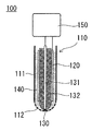
上記二酸化塩素濃度測定器100は、センサヘッド部110と電位規制部150とを備える2電極式の定電位電気化学式濃度測定器であり、必要に応じて、校正用標準ガス発生器を有して成る。
The two-electrode chlorine dioxide concentration measuring device of the present invention will be described in detail.
The chlorine dioxide
上記二酸化塩素濃度測定器は、上記センサヘッド部110内部の電解液140中に二酸化塩素ガスを取り込む。そして電位規制部によって、作用電極130の電位を、作用電極における電気化学反応が選択的に二酸化塩素の反応となる電位に規制すると共に、上記作用電極130に流れる電解電流を検出して二酸化塩素の濃度を測定する。
The chlorine dioxide concentration measuring device takes in chlorine dioxide gas into the
<センサヘッド部>
図1にセンサヘッド部の断面図を示す。
上記センサヘッド部110は、図1に示すように、ガス透過膜112を有する容器111内に、電解液140と対極120と作用電極130とを備え、対極と作用電極とが電解液中に浸された構造を有する。
そして、上記ガス透過膜112を介して電解液中に二酸化塩素を取り込み、上記対極120と上記作用電極130とが上記電解液を介して電子の授受を行う。
<Sensor head part>
FIG. 1 shows a cross-sectional view of the sensor head portion.
As shown in FIG. 1, the
Then, chlorine dioxide is taken into the electrolytic solution through the gas
本発明においては、対極と電解液との界面での電極反応に速い電極系を選択し、かつ対極の面積を作用極の面積に比べて充分大きくすることで対極における電極−電解液界面が非分極であるとみなすことができ、2電極式において、定電圧電解方式ではなく、定電位電解方式による二酸化塩素の濃度測定が可能である。 In the present invention, by selecting an electrode system that has a fast electrode reaction at the interface between the counter electrode and the electrolytic solution and making the area of the counter electrode sufficiently larger than the area of the working electrode, the electrode-electrolyte solution interface at the counter electrode is not formed. It can be regarded as polarization, and in the two-electrode method, it is possible to measure the concentration of chlorine dioxide by a constant potential electrolysis method instead of a constant voltage electrolysis method.
(対極)
本発明においては、上記対極120としては、AgCl/Ag系の電極を用いる。
AgCl/Ag系の電極は、電極反応が非常に速く、後述する作用電極と電解液との接触面積に対して大きく、対極と電解液との接触面積が充分大きいことで、対極と電解液との界面が非分極界面であるとみなすことができ、参照電極を兼ねることができる。
なお、理論的には、AgCl/Ag系の電極に代えて、Br/(AgBr)や、I/(AgI)などの、難溶性でかつ電極反応が速い電極を用いることもできるが、ClO2−のAg側への流入を避ける工夫が必要となる。
(Opposite pole)
In the present invention, an AgCl / Ag-based electrode is used as the
The AgCl / Ag-based electrode has a very fast electrode reaction, is large with respect to the contact area between the working electrode and the electrolytic solution, which will be described later, and the contact area between the counter electrode and the electrolytic solution is sufficiently large. The interface can be regarded as a non-polarizing interface and can also serve as a reference electrode.
Theoretically, instead of the AgCl / Ag-based electrode, an electrode such as Br / (AgBr) or I / (AgI), which is sparingly soluble and has a fast electrode reaction, can be used, but ClO 2 It is necessary to devise to avoid the inflow of − to the Ag side.
上記対極と電解液との接触面積は、作用電極と電解液との接触面積の100倍以上であれば、特に上限はないが、例えば5000倍を超えるとセンサヘッド部が大きくなるため、実用上は5000倍以下であることが好ましい。 If the contact area between the counter electrode and the electrolytic solution is 100 times or more the contact area between the working electrode and the electrolytic solution, there is no particular upper limit, but if it exceeds 5000 times, for example, the sensor head portion becomes large, so that it is practically used. Is preferably 5000 times or less.
上記対極の形状は、電解液との接触面積を大きくできればよく、波板形状や円筒形状など特に制限はないが、例えば、直径が5mm〜10mm、長さが30mm〜50mmの円筒形であるとセンサヘッド部を小型化することができる。
また、センサヘッド部内の後述する電解液の量を少なくすることができ、電解液中の二酸化塩素濃度が短時間で平衡になり、測定時間を短縮することができる。
The shape of the counter electrode is not particularly limited as long as the contact area with the electrolytic solution can be increased, such as a corrugated plate shape or a cylindrical shape. For example, the shape of the counter electrode is a cylindrical shape having a diameter of 5 mm to 10 mm and a length of 30 mm to 50 mm. The sensor head portion can be miniaturized.
Further, the amount of the electrolytic solution described later in the sensor head portion can be reduced, the chlorine dioxide concentration in the electrolytic solution becomes equilibrated in a short time, and the measurement time can be shortened.
(作用電極)
上記作用電極130は、ガス透過膜112の近傍で電極反応を行うものであり、図1に示すように、ガラスなどの絶縁体132によって絶縁された導線131の先端に設けられて、上記容器のガス透過膜の近傍に配置される。
(Working electrode)
The working
上記作用電極としては、ClO2の電極反応が速く、化学的に安定で200〜500mVの範囲において電気化学測定が可能であればよく、例えば、白金(Pt)、二酸化ルテニウム(RuO2)やボロンドープダイヤモンド等を使用することができる。 As the working electrode, it is sufficient that the electrode reaction of ClO 2 is fast, chemically stable, and electrochemical measurement is possible in the range of 200 to 500 mV. For example, platinum (Pt), ruthenium dioxide (RuO 2 ), or boron. Dope diamond or the like can be used.
また、上記作用電極は、直径0.3mm〜1mmの円盤状などの面積が小さな電極であることが好ましい。
作用電極の大きさが上記範囲であることで、センサヘッド部の大きさを長さ10cm程度にすることができ、2電極式・定電位電解二酸化塩素濃度測定器を小型化することができる。
Further, the working electrode is preferably an electrode having a small area such as a disk shape having a diameter of 0.3 mm to 1 mm.
When the size of the working electrode is within the above range, the size of the sensor head portion can be set to about 10 cm in length, and the two-electrode type constant potential electrolytic chlorine dioxide concentration measuring device can be miniaturized.
(電解液)
上記電解液140は、塩化物イオン(Cl−)を含む。電解液が塩化物イオンを含むことで、上記対極との界面を非分極界面であるとみなすことができる。
(Electrolytic solution)
The
塩化物イオンを解離発生する支持電解質としては、塩化ナトリウム(NaCl)、塩化カリウム(KCl)などを使用でき、上記電解液中の濃度は、常識的な範囲であれば良く例えば、0.1〜1.0mol/L 程度である。 Sodium chloride (NaCl), potassium chloride (KCl), or the like can be used as the supporting electrolyte that dissociates chloride ions, and the concentration in the electrolytic solution may be within a range of common sense, for example, 0.1. It is about 1.0 mol / L.
センサヘッド部内の電解液の量は、上記対極との接触面積を確保できればよく、特に制限はないが、電解液の量が少ないことで二酸化塩素が短時間で平衡に達するため、例えば、1〜5mLであることが好ましい。 The amount of the electrolytic solution in the sensor head portion is not particularly limited as long as the contact area with the counter electrode can be secured. However, since chlorine dioxide reaches equilibrium in a short time due to the small amount of the electrolytic solution, for example, 1 to 1 It is preferably 5 mL.
(容器)
上記ガスセンサの容器111は、少なくとも一部にガス透過膜112を有する。上記ガス透過膜112は、例えば、円筒形の容器の底部などの先端部に設けられ、二酸化塩素は上記ガス透過膜を透過して電解液に溶け込む。
(container)
The
上記容器としては、絶縁性であるものを使用でき、例えば、ガラス製、樹脂製、セラミックス製の容器を使用できる。
また、上記ガス透過膜としては、ガスを通し、かつ電解液を通さないものを使用することができ、例えば、シリコン製のガス透過膜等を挙げることができる。
As the container, an insulating container can be used, and for example, a container made of glass, resin, or ceramics can be used.
Further, as the gas permeable membrane, a membrane that allows gas to pass through and does not allow the electrolytic solution to pass through can be used, and examples thereof include a gas permeable membrane made of silicon.
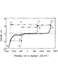
ここで、塩化物イオン(Cl−)を含む電解液中のAgCl/Ag電極を対極兼参照電極とし、作用電極の電位を直線的に掃引したときのサイクリックボルタモグラムを図2に示す。
図2の形状から、ClO2/ClO2 −系の電極反応速度は非常に速く、かつ広い限界拡散電流領域を持つことがわかる。
Here, FIG. 2 shows a cyclic voltammogram when the AgCl / Ag electrode in the electrolytic solution containing chloride ion (Cl − ) is used as a counter electrode and a reference electrode, and the potential of the working electrode is swept linearly.
From the shape of FIG. 2, it can be seen that the electrode reaction rate of the ClO 2 / ClO 2 - system is very fast and has a wide critical diffusion current region.
そして、本発明においては、AgCl/Ag電極(対極)と電解液との接触面積が、上記作用電極と上記電解液との接触面積の100倍以上であって充分大きいため、分極抵抗が大幅に低下し、AgCl/Ag電極(対極)と電解液との界面が非分極界面であるとみなすことができる。 In the present invention, the contact area between the AgCl / Ag electrode (counter electrode) and the electrolytic solution is 100 times or more the contact area between the working electrode and the electrolytic solution, which is sufficiently large, so that the polarization resistance is significantly increased. It decreases, and the interface between the AgCl / Ag electrode (counter electrode) and the electrolytic solution can be regarded as a non-polarizing interface.
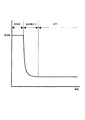
また、上記電極系でClO2をClO2−に還元するときの電気化学的還元反応を通常の3電極式ポテンショスタットで測定した白金電極(作用電極)の電流−電位曲線を図3に示す。 Further, FIG. 3 shows a current-potential curve of the platinum electrode (working electrode) obtained by measuring the electrochemical reduction reaction when reducing ClO 2 to ClO 2- in the above electrode system with a normal three-electrode potentiostat.
図3から、およそ200mV〜500mVの範囲において、電流値がほほ一定(ほぼ平坦)であり、ClO2/ClO2 −系の電極反応は、上記範囲内において、Cl2、ClO−やClO3 −などの他の原子価の塩素を含まず、作用電極に二酸化塩素の還元電流のみが流れ、電流が電位に依存しない限界拡散電流となっていることがわかる。
なお、上記限界拡散電流が流れる電位の範囲外、およそ200mV以下の電位では酸素の還元が起こり易くなり、500mVを超える電位では電流値が電位依存的に急激に減少するので電流値とClO2濃度の比例関係が保証できなくなる。
From FIG. 3, the current value is almost constant (almost flat) in the range of about 200 mV to 500 mV, and the electrode reaction of the ClO 2 / ClO 2 - system is within the above range of Cl 2 , ClO − and ClO 3 −. It can be seen that chlorine dioxide with other valences such as chlorine is not contained, and only the reduction current of chlorine dioxide flows through the working electrode, and the current is a limit diffusion current independent of the potential.
Incidentally, out of the range of potential where the limiting diffusion current flows, is likely to occur oxygen reduction approximately 200mV below potential, current because the potential of more than 500mV current value decreases the potential-dependent manner rapidly and ClO 2 concentration Proportional relationship cannot be guaranteed.
したがって、作用電極の電位を限界拡散電流の範囲内で電位を設定し作用電極に流れる電流を測定したときの二酸化塩素の濃度と電流値は、1pA〜1000mAの範囲で厳密に比例関係を示す。 Therefore, when the potential of the working electrode is set within the range of the limit diffusion current and the current flowing through the working electrode is measured, the concentration of chlorine dioxide and the current value show a strict proportional relationship in the range of 1 pA to 1000 mA.
このように、作用電極の電位が限界拡散電流の範囲内においては、作用電極に二酸化塩素の還元電流のみが流れることから、第3の参照電極による電位制御が不要となり、本発明においては、対極が参照電極を兼ねることができ、2電極式の定電位電解方式により、安定かつ再現性良く二酸化塩素ガスの濃度を測定することができる。 As described above, when the potential of the working electrode is within the limit diffusion current range, only the reduction current of chlorine dioxide flows through the working electrode, so that the potential control by the third reference electrode becomes unnecessary, and in the present invention, the counter electrode Can also serve as a reference electrode, and the concentration of chlorine dioxide gas can be measured stably and with good reproducibility by the two-electrode constant-potential electrolysis method.
上記センサヘッド部は、図1に示すように、対極と作用電極とが電位規制部150に接続している。
In the sensor head portion, as shown in FIG. 1, the counter electrode and the working electrode are connected to the
(電位規制部)
上記電位規制部は、図示しない定電圧電源部と電流検出部とを備え、作用電極130の電位を、作用電極における電気化学反応が選択的に二酸化塩素の反応となる電位に規制すると共に、上記作用電極130に流れる電解電流を検出して二酸化塩素の濃度を測定するものである。
(Potential regulation part)
The potential regulating unit includes a constant voltage power supply unit and a current detecting unit (not shown), and regulates the potential of the working
上記定電圧電源部は、上記作用電極で電気分解を生じさせる直流電源であり、常法にしたがって電圧を規制する適切な信号波形を印加することにより、出力電圧の制御が可能なものである。そして、本発明のセンサヘッド部の上記2電極間の電圧を限界拡散電流の範囲内に規制した定電圧とすることで、作用電極の電位が一定になって定電位電解となる。 The constant voltage power supply unit is a DC power supply that causes electrolysis at the working electrode, and the output voltage can be controlled by applying an appropriate signal waveform that regulates the voltage according to a conventional method. Then, by setting the voltage between the two electrodes of the sensor head portion of the present invention to a constant voltage regulated within the range of the limit diffusion current, the potential of the working electrode becomes constant and constant potential electrolysis is performed.
また、上記電流検出部は、上記作用電極における電気分解によって生じた電流を検出して、これを電圧として出力する電流計を有する。 Further, the current detection unit has an ammeter that detects the current generated by electrolysis in the working electrode and outputs the current as a voltage.
<校正用標準ガス発生器>
校正用標準ガス発生器は、二酸化塩素濃度測定器を校正する標準ガスを供給するものであり、電流値とキャリアガスの流量により発生する二酸化塩素ガスの濃度を制御できるものである。
<Standard gas generator for calibration>
The calibration standard gas generator supplies the standard gas for calibrating the chlorine dioxide concentration measuring device, and can control the concentration of chlorine dioxide gas generated by the current value and the flow rate of the carrier gas.
上記校正用標準ガス発生器は、ガス通過性を有するガス発生電極と、上記ガス発生電極と逆極性の対電極と、上記両電極間に直流電流を印加する定電流電源部と、原料のNaClO2および支持電解質としてのNaClを含む電解液と、上記電解液を貯留する電解液槽と、上記電解液槽からの電解液を上記ガス発生電極に導く電解液導通部材と、を備える。 The standard gas generator for calibration includes a gas generating electrode having gas permeability, a counter electrode having a polarity opposite to that of the gas generating electrode, a constant current power supply unit for applying a DC current between both electrodes, and a raw material NaClO. 2. An electrolytic solution containing NaCl as a supporting electrolyte, an electrolytic solution tank for storing the electrolytic solution, and an electrolytic solution conducting member for guiding the electrolytic solution from the electrolytic solution tank to the gas generating electrode are provided.
上記校正用標準ガス発生器は、ガス発生電極と対電極との間に直流電流を印加すると、NaClO2およびNaClを含む電解液の電気分解が起こり、ファラデーの法則に遵って電流効率がほぼ100%で二酸化塩素を発生し、さらに後述する適切な装置的工夫をすることにより、水への溶解度が高い二酸化塩素を気体として得ることができる。 In the above standard gas generator for calibration, when a DC current is applied between the gas generating electrode and the counter electrode, electrolysis of the electrolytic solution containing NaClO 2 and NaCl occurs, and the current efficiency is almost in accordance with Faraday's law. Chlorine dioxide is generated at 100%, and chlorine dioxide having high solubility in water can be obtained as a gas by further devising an appropriate device described later.
ここで、ClO2/ClO2 −系の可逆電極反応について説明する。
図4は、NaClを支持電解質とし、NaClO2を含む電解液中での白金電極の電流−電位曲線(図4中のA〜B)と、NaClのみを含む電解液の電流−電位曲線(図4中のC〜D)である。
Here, the reversible electrode reaction of the ClO 2 / ClO 2 - system will be described.
FIG. 4 shows a current-potential curve (A to B in FIG. 4) of a platinum electrode in an electrolytic solution containing NaCl O 2 and a current-potential curve of an electrolytic solution containing only NaCl (FIG. 4). C to D) in 4.
図4から、NaClO2とNaClを含む溶液に酸化電流を流すとClO2 −の電解酸化によりClO2ガスを選択的に発生(図4中のA)させることができ、このClO2ガスにはCl2ガスはほとんど含まれないことがわかる。
また、NaClだけを含む溶液に酸化電流を流すとCl2のみが発生(図4中のC)して、ClO2ガスを含まれないことがわかる。
なお、図4中、Dは、H2ガスの発生であり、ClO2−の電解還元ではH2が殆ど発生しないことを保証している。また0V付近より卑の電位で観測される還元電流は(大気に含まれる)酸素の還元電流を表わす。
4, when supplying an oxygen current in a solution containing NaClO 2 and NaCl ClO 2 - of the ClO 2 gas selectively generated can be (A in FIG. 4) by electrolytic oxidation, this ClO 2 gas It can be seen that Cl 2 gas is hardly contained.
Further, it can be seen that when an oxidation current is passed through a solution containing only NaCl, only Cl 2 is generated (C in FIG. 4), and ClO 2 gas is not contained.
In FIG. 4, D is the generation of H 2 gas, and it is guaranteed that H 2 is hardly generated by the electrolytic reduction of ClO 2-. The reduction current observed at a potential lower than around 0 V represents the reduction current of oxygen (contained in the atmosphere).
図4に示すように、ClO2ガスの発生時、およびCl2ガスの発生時においては、いずれも他の反応を含まない。
そして、ClO2ガスを発生する電位とCl2ガスを発生する電位とは、1V以上離れているので、電解液中にNaClO2が含まれるかぎり、ClO2ガスとCl2ガスとが同時に発生することはなく、NaClO2とNaClを含む電解液中で定電流電解(図4中、P→Q)を行うと、電流効率がほぼ100%でClO2を発生させることができる。
As shown in FIG. 4, upon the occurrence of ClO 2 gas, and Cl 2 in the event of a gas, both free of other reactions.
Since the potential for generating ClO 2 gas and the potential for generating Cl 2 gas are separated by 1 V or more , Cl O 2 gas and Cl 2 gas are generated at the same time as long as NaCl O 2 is contained in the electrolytic solution. However, when constant current electrolysis (P → Q in FIG. 4) is performed in an electrolytic solution containing NaClO 2 and NaCl, ClO 2 can be generated with a current efficiency of almost 100%.
つまり、ClO2 −を含む電解液中で電流規制電解をおこなうことにより、陽極(作用極)ではClO2 −の電解酸化反応のみが起こってClO2が発生し、陰極(対極)ではClO2 −の還元反応(最終生成物はCl−)が起こって、水素は発生しない。 That, ClO 2 - by performing current regulation electrolysis in an electrolyte containing an anode (working electrode), the ClO 2 - only electrolytic oxidation reaction ClO 2 is generated happening of a cathode (counter electrode) in ClO 2 - (The final product is Cl − ) occurs and hydrogen is not generated.
また、上記校正用標準ガス発生器は、上記対電極が上記電解液に接触する一方で、上記ガス発生電極は、一方の面が上記電解液導通部材に導かれた電解液に接触し他方の面が気相に部分的に露出している。 Further, in the calibration standard gas generator, the counter electrode is in contact with the electrolytic solution, while the gas generating electrode is in contact with the electrolytic solution in which one surface is guided to the electrolytic solution conductive member and the other. The surface is partially exposed to the gas phase.
上記校正用標準ガス発生器においては、ガス発生電極と電解液との接触部位、すなわち、気相、液相(電解液)及び固相(電極)の三相が接触する部位、及び、液相(電解液)と固相(電極)との二相が接触する部位で二酸化塩素ガスが発生する。 In the above standard gas generator for calibration, the contact portion between the gas generating electrode and the electrolytic solution, that is, the portion where the three phases of the gas phase, the liquid phase (electrolyte solution) and the solid phase (electrode) contact, and the liquid phase. Chlorine dioxide gas is generated at the site where the two phases of the (electrolyte) and the solid phase (electrode) come into contact with each other.
そして、上記ガス発生電極がガス通気性を有するものであるため、上記三相が接触する部位で発生した二酸化塩素ガスは直ちに気相に放出される。
また、上記二相が接触する部位で発生した二酸化塩素ガスは、理論上、電解液に溶解するが、ガス発生電極の上方には電解液(特に電解液の層)が存在しないので、実質的に遅延することなく二酸化塩素ガスが気相に放出される。
Since the gas generating electrode has gas permeability, chlorine dioxide gas generated at the site where the three phases come into contact is immediately released to the gas phase.
Further, the chlorine dioxide gas generated at the site where the two phases come into contact is theoretically dissolved in the electrolytic solution, but since the electrolytic solution (particularly the layer of the electrolytic solution) does not exist above the gas generating electrode, it is substantially present. Chlorine dioxide gas is released into the gas phase without delay.
したがって、本発明の校正用標準ガス発生器は、上記電流効率がほぼ100%でClO2を発生させることができることと、発生したClO2が実質的に遅延することなく気相に放出されることとが相俟って、印可電流とガス発生電極で発生する二酸化塩素ガスの濃度とが厳密に比例関係を示すため、印可電流とキャリアガスの流量とから、発生する二酸化塩素ガスの濃度を厳密に制御することができ、濃度が既知の標準ガスを容易に得ることができる。 Therefore, the standard gas generator for calibration of the present invention can generate ClO 2 with the above current efficiency of almost 100%, and the generated ClO 2 is released to the gas phase without substantially delaying. In combination with, the applied current and the concentration of chlorine dioxide gas generated at the gas generating electrode show a strict proportional relationship, so the concentration of chlorine dioxide gas generated is strictly determined from the applied current and the flow rate of the carrier gas. It is possible to easily obtain a standard gas having a known concentration.
上記校正用標準ガス発生器の具体的な構造について説明する。
図5は、本発明の校正用標準ガス発生器の一例を示す断面図である。
上記校正用標準ガス発生器は、図5に示すように、ガス発生電極10と、ガス発生電極10とは極性が逆の対電極20と、この両極間に直流電流を印加する定電流電源部(図示せず)と、NaClO2およびNaClを含む電解液30と、電解液30を貯留する有底円筒状の電解液槽40と、電解液導通部材50を備えている。
The specific structure of the standard gas generator for calibration will be described.
FIG. 5 is a cross-sectional view showing an example of the calibration standard gas generator of the present invention.
As shown in FIG. 5, the calibration standard gas generator includes a
上記電解液導通部材50は、電解液を含んでガス発生電極10に電解液を接触させる保液部と、上記保液部に電解液を供給する液絡部(以下、「ジャンクション」ということがある。)と、を備えている。
The electrolytic solution
電解液槽40には中央に凹部を有する円板状の液相蓋70が装着され、さらに液相蓋70の中央凹部に円板状の気相蓋71が装着されている。
A disk-shaped
上記液相蓋70は、対電極ガス出口23を有し、対電極20から発生するガスを放出し、かつ電解液槽40内を外圧と同圧に保つ。
The
上記気相蓋71は、エア等のキャリアガスを取り込むキャリアガス入口13と、二酸化塩素とキャリアガスの混合ガスを放出する標準ガス出口14を有している。
The
液相蓋70は電解液槽40を覆っており、液相蓋70の外周面と電解液槽40の内周面との間にはOリング80が装着され、両者間の気密性が担保されている。
The
一方、気相蓋71が液相蓋70の中央凹部を覆うことにより、電解液槽40の上方にガス発生室60が形成されており、気相蓋71の外周面と液相蓋70の内周面との間にはOリング81が装着されており、両者間の気密性が担保されている。
なお、電解液30は、後述する電解液導通部材50を介してガス発生電極10に導かれるが、ガス発生室60には直接進入できない。このことは、電解液30の液面30fと液相蓋70の底部70bとの間に間隙を設けることにより、簡易に実現することができる。
On the other hand, since the
Although the
対電極20は、対電極板21に対電極リード22を連結して形成され、電解液30に浸漬されている。対電極リード22は液相蓋70を貫通し、図示しない定電流電源部と電気接続されている。
The
一方、ガス発生電極10は、例えばメッシュ状でガス通過性を有するガス発生電極網11が、ガス発生電極リード12が連結されて平面形状が円形をなして形成される。
上記ガス発生電極リード12は気相蓋71を貫通し、図示しない電流印加手段と電気接続されている。
On the other hand, the
The gas generating electrode lead 12 penetrates the
そして、ガス発生電極10は、一方の面が上記電解液導通部材に導かれた電解液に接触し他方の面が気相に部分的に露出して配置されている。
すなわち、ガス発生電極10は、ガス発生電極網11の上面がガス発生室60に露出する一方で、下面が電解液導通部材50の保液部と接触するように、電解液導通部材50のジャンクションによって保液部に導かれた電解液と気相との界面に配置されている。
Then, one surface of the
That is, in the
上記電解液導通部材50は、親水性材料で形成されており画鋲のような形状をなしている。画鋲状の電解液導通部材50の脚部(ジャンクション)51は、電解液30に浸漬されており、樹脂製の保護管51pで部分的に覆われている。
The electrolytic solution
一方、電解液導通部材50の頂面(保液部)52は、ガス発生電極10のガス発生電極網11と接触しており、ガス発生電極10に電解液30を供給できるようになっている。
On the other hand, the top surface (liquid holding portion) 52 of the electrolytic solution
上記校正用標準ガス発生器においては、ガス発生電極10が保液部の電解液30に接しており、保液部の電解液量が少ないため、発生した二酸化塩素ガスが電解液に溶解したとしても、電解液中の二酸化塩素濃度が直ぐに高濃度に達するため、上記ガス通過性のガス発生電極と相俟って、発生した二酸化塩素ガスは遅延することなく直ちに気相に放出される。
In the above standard gas generator for calibration, since the
次に、上記校正用標準ガス発生器おける各種部材・要素の機能や材質について説明する。 Next, the functions and materials of various members / elements in the standard calibration gas generator will be described.
(ガス発生電極と対電極)
ガス発生電極は二酸化塩素ガスを発生させる電極であり、対電極は水素ガスを発生せずにClO2−のみを還元する電極である。
(Gas generating electrode and counter electrode)
The gas generating electrode is an electrode that generates chlorine dioxide gas, and the counter electrode is an electrode that reduces only ClO 2- without generating hydrogen gas.
ガス発生電極は、二酸化塩素ガスを発生させるものであって陽極となる。
ガス発生電極陽極の材料としては、白金(Pt)、イリジウム(Ir)、ルテニウム(Ru)、及びチタン(Ti)にルテニウムメッキや白金メッキを施した材料などを挙げることができる。
The gas generating electrode generates chlorine dioxide gas and serves as an anode.
Examples of the material of the gas generating electrode anode include platinum (Pt), iridium (Ir), ruthenium (Ru), and titanium (Ti) plated with ruthenium or platinum.
本発明において、ガス発生電極は、ガス通過性を有する必要があり、例えば、孔開き金属板(パンチングメタル)、金属の網状体、発泡金属等の金属材料を用いることができる。 In the present invention, the gas generating electrode needs to have gas permeability, and for example, a metal material such as a perforated metal plate (punching metal), a metal mesh, or a foamed metal can be used.
また、ガス発生電極の形状(全体形状)は、矩形板状や円板状などの板状でよく、適宜に湾曲部や折り曲げ部を有していてもよい。 Further, the shape (overall shape) of the gas generating electrode may be a plate shape such as a rectangular plate shape or a disk shape, and may have a curved portion or a bent portion as appropriate.
また、上記対電極は陰極であり、対電極の構成材料としては、白金、ルテニウム、ステンレス鋼、及びチタンにルテニウムメッキを施した材料などを挙げることができる。
なお、これらの電極は、不溶性電極(商品名DSA)として市場で入手することも可能である。
Further, the counter electrode is a cathode, and examples of the constituent material of the counter electrode include platinum, ruthenium, stainless steel, and a material obtained by plating titanium with ruthenium.
These electrodes can also be obtained on the market as insoluble electrodes (trade name DSA).
(定電流電源部)
定電流電源部は、ガス発生電極と対電極との間に直流電流を供給できればよく、特に制限はないが、電流波形を任意に変更可能なプログラマブル電流規制電源であることが好ましい。
(Constant current power supply)
The constant current power supply unit is not particularly limited as long as it can supply a direct current between the gas generating electrode and the counter electrode, but it is preferably a programmable current regulated power supply capable of arbitrarily changing the current waveform.
本発明においては、ガス発生電極の一方の面が電解液導通部材に導かれた電解液に接触し、他方の面が気相に部分的に露出しており、発生した二酸化塩素ガスが直ちに気相に放出されるが、二酸化塩素が水に溶解し易いため、二酸化塩素が定常的に発生するまでに時間がかかることがある。 In the present invention, one surface of the gas generating electrode is in contact with the electrolytic solution guided to the electrolytic solution conducting member, the other surface is partially exposed to the gas phase, and the generated chlorine dioxide gas is immediately vaporized. Although released into the phase, it may take some time for chlorine dioxide to be constantly generated because chlorine dioxide is easily dissolved in water.
上記プログラマブル電流規制電源により、図6に示すように、通電初期に大電流を流した後に級数的に減少させ、その後、一定である電流波形に制御することで、早期に定常状態となって標準ガスを発生させることができる。 As shown in FIG. 6, the programmable current regulated power supply causes a large current to flow in the initial stage of energization, then reduces it serieswise, and then controls the current waveform to be constant, so that it becomes a steady state at an early stage and becomes a standard. Can generate gas.
つまり、二酸化塩素の発生量が過大にならない範囲の高電流を通電初期に流すことで、電解液導通部材の保液部に含まれる電解液中の二酸化塩素が短時間で飽和する。
そして、飽和状態を維持したまま電流値を級数的に減少させることで、所望の濃度の二酸化塩素ガスを発生させるファラデーの法則から計算される理論電流値まで短時間で電流値を下げることができ、短時間で定常状態にすることができるため、早期に標準ガスによる校正を開始でき、その後、上記理論電流値で一定にすることで、放出する二酸化塩素ガスの濃度を長時間一定に保たれて安定した校正が可能になる。
That is, by passing a high current in a range in which the amount of chlorine dioxide generated does not become excessive at the initial stage of energization, chlorine dioxide in the electrolytic solution contained in the liquid holding portion of the electrolytic solution conductive member is saturated in a short time.
Then, by reducing the current value systematically while maintaining the saturated state, the current value can be reduced in a short time to the theoretical current value calculated from Faraday's law that generates chlorine dioxide gas of a desired concentration. Since the steady state can be achieved in a short time, calibration with standard gas can be started at an early stage, and then by keeping the theoretical current value constant, the concentration of chlorine dioxide gas released can be kept constant for a long time. And stable calibration is possible.
(電解液)
電解液は、電気分解により二酸化塩素ガスを発生させるためのガス発生原料となる電解質と伝導度を増すための支持電解質を含んでいる水溶液であり、NaClO2およびNaClを含有する。
(Electrolytic solution)
The electrolytic solution is an aqueous solution containing an electrolyte as a gas generating raw material for generating chlorine dioxide gas by electrolysis and a supporting electrolyte for increasing conductivity, and contains NaClO 2 and NaCl.
(電解液槽)
電解液槽としては、上記の電解液を貯留できればよく特に限定されるものではない。例えば、ガラス製、樹脂製、セラミックス製及び金属製などの各種容器を例示できる。
(Electrolytic solution tank)
The electrolytic solution tank is not particularly limited as long as the above electrolytic solution can be stored. For example, various containers made of glass, resin, ceramics, metal, etc. can be exemplified.
(電解液導通部材)
電解液導通部材としては、電解液をガス発生電極に導く機能を有するものであれば、特に限定されるものではない。
具体的には、親水性や含水性、保水性を有する材料から成るものがあり、例えば親水性繊維の織布や不織布、成形体などの繊維集合体が挙げられる。親水性材料としては、ガラス繊維、ろ紙、綿及びセラミックス多孔質体などを例示できる。
(Electrolytic solution conducting member)
The electrolytic solution conducting member is not particularly limited as long as it has a function of guiding the electrolytic solution to the gas generating electrode.
Specific examples thereof include materials having hydrophilicity, water content, and water retention, and examples thereof include fiber aggregates such as woven fabrics, non-woven fabrics, and molded bodies of hydrophilic fibers. Examples of the hydrophilic material include glass fiber, filter paper, cotton, and porous ceramics.
電解液導通部材の形状も特に限定されるものではないが、ガス発生効率を考慮すると、ガス発生電極との接触面積が大きくなるような形状を有することが好ましい。
例えば、ガス通過性のガス発生電極が板状の電極を有する場合、電解液導通部材も当該電極を積層できる形状や、挟持できるような形状の部位を有することが好ましい。
The shape of the electrolytic solution conductive member is not particularly limited, but in consideration of gas generation efficiency, it is preferable to have a shape such that the contact area with the gas generation electrode is large.
For example, when the gas-passing gas generating electrode has a plate-shaped electrode, it is preferable that the electrolytic solution conducting member also has a portion having a shape in which the electrodes can be laminated or a portion having a shape that can be sandwiched.
典型的には、上記ガス発生電極が円板状の電極とこれに接続された電極リードを有する場合、電解液導通部材は、円板状の電極を積層し得る頂面を有する画鋲状の形状を有することが好ましい。 Typically, when the gas generating electrode has a disc-shaped electrode and an electrode lead connected to the disc-shaped electrode, the electrolytic solution conducting member has a thumbtack-shaped shape having a top surface on which the disc-shaped electrodes can be laminated. It is preferable to have.
この場合、画鋲状の形状の頂面部分の厚さは0.1mm〜0.5mm程度とするのがよいが、薄いと頂面に溶解する二酸化塩素ガスが少なくなって短時間に二酸化塩素ガスが得られる反面、ガス発生原料が容易に消費されてしまい、脚部を介する電解液供給が不十分な場合には、二酸化塩素ガス発生量が減少してしまうので、電極の面積や装置全体の大きさ、意図するガス発生量などから適宜変更することが望ましい。 In this case, the thickness of the top surface portion of the thumbtack shape should be about 0.1 mm to 0.5 mm, but if it is thin, the chlorine dioxide gas dissolved in the top surface will decrease and the chlorine dioxide gas will be dissolved in a short time. On the other hand, if the gas generating raw material is easily consumed and the electrolyte supply via the legs is insufficient, the amount of chlorine dioxide gas generated decreases, so the area of the electrode and the entire device It is desirable to change the size and the intended amount of gas generated as appropriate.
なお、本発明においては、電解液導通部材とこれに電解液を送るポンプ等の圧送手段を併用することができ、これにより電解液のガス発生電極への供給を促進することができる。
電解液は電解液槽から供給すればよく、ポンプとしては、連続式又は必要に応じて一定量を所定回供給する回分式のいずれでもよい。
この場合、保持可能な電解液量が電解液導通部材に保持され、余剰の電解液は電解液導通部材から流出する。
In the present invention, the electrolytic solution conductive member and a pressure feeding means such as a pump for sending the electrolytic solution to the electrolytic solution conductive member can be used in combination, whereby the supply of the electrolytic solution to the gas generating electrode can be promoted.
The electrolytic solution may be supplied from the electrolytic solution tank, and the pump may be a continuous type or a batch type in which a fixed amount is supplied a predetermined amount as needed.
In this case, the amount of the electrolytic solution that can be held is held by the electrolytic solution conducting member, and the excess electrolytic solution flows out from the electrolytic solution conducting member.
(キャリアガス)
本発明において、二酸化塩素ガスは気相中に放出されるが、放出されたガス二酸化塩素ガスをキャリアガスにより流通させて、上記センサヘッド部に送ることができる。
かかるキャリアガスとしては、エア(空気)や窒素ガス、不活性ガスを挙げることができる。
(Carrier gas)
In the present invention, the chlorine dioxide gas is released into the gas phase, and the released gas chlorine dioxide gas can be circulated by the carrier gas and sent to the sensor head portion.
Examples of such a carrier gas include air (air), nitrogen gas, and an inert gas.
<二酸化塩素濃度測定器の校正>
本発明の二酸化塩素濃度測定器は、上記校正用標準ガス発生器により二酸化塩素の標準ガスを発生させ、上記センサヘッド部に送ることで二酸化塩素濃度測定器の校正を行うことができる。
<Calibration of chlorine dioxide concentration measuring instrument>
In the chlorine dioxide concentration measuring device of the present invention, the chlorine dioxide concentration measuring device can be calibrated by generating the standard gas of chlorine dioxide by the calibration standard gas generator and sending it to the sensor head unit.
具体的には、マスフローメータを介してコンプレッサーを校正用標準ガス発生器のキャリアガス入口に接続し、校正用標準ガス発生器の標準ガス出口から放出される二酸化塩素の標準ガスが流通する経路内にセンサヘッド部を配置する。 Specifically, the compressor is connected to the carrier gas inlet of the calibration standard gas generator via a mass flow meter, and the standard gas of chlorine dioxide released from the standard gas outlet of the calibration standard gas generator flows in the path. The sensor head part is arranged in.
校正用標準ガス発生器は、マスフローメータで流量が一定に保たれたキャリアガスを導入すると共に定電流電解を行い、標準ガスを放出してセンサヘッド部に送る。 The calibration standard gas generator introduces a carrier gas whose flow rate is kept constant by a mass flow meter, performs constant current electrolysis, releases the standard gas, and sends it to the sensor head.
センサヘッド部は、本来未知濃度の二酸化塩素濃度を測定する装置である一方、送られてくる標準ガスを定電位電解して、電流として出力する。校正用標準ガス発生器が発生する標準ガスの二酸化塩素の濃度が安定したか否かをモニタする機能も有する。 The sensor head unit is a device that originally measures the concentration of chlorine dioxide, which is an unknown concentration, while the standard gas that is sent is electrolyzed at a constant potential and output as an electric current. It also has a function to monitor whether the concentration of chlorine dioxide in the standard gas generated by the calibration standard gas generator is stable.
そして、センサヘッド部で検出した標準ガス中の二酸化塩素濃度が、校正用標準ガス発生器に流した電流値とキャリアガスの流量とから、ファラデーの法則によって計算された理論濃度付近で一定になったら、センサヘッド部から出力する二酸化塩素濃度の値を上記理論濃度に校正する。
なお、校正用標準ガス発生器を稼動させてから発生する二酸化塩素の濃度が安定する(定常状態となる)までの時間を予め測定しておき、校正用標準ガス発生器を稼動させてから一定時間経過後に校正を行ってもよい。
Then, the chlorine dioxide concentration in the standard gas detected by the sensor head becomes constant near the theoretical concentration calculated by Faraday's law from the current value flowing through the calibration standard gas generator and the flow rate of the carrier gas. Then, calibrate the value of chlorine dioxide concentration output from the sensor head to the above theoretical concentration.
The time from when the calibration standard gas generator is operated until the concentration of chlorine dioxide generated becomes stable (becomes a steady state) is measured in advance, and it is constant after the calibration standard gas generator is operated. Calibration may be performed after a lapse of time.
以下、本発明を実施例及び比較例により更に詳細に説明するが、本発明はこれら実施例に限定されるものではない。 Hereinafter, the present invention will be described in more detail with reference to Examples and Comparative Examples, but the present invention is not limited to these Examples.
[校正用標準ガスの発生]
図5に示す校正用標準ガス発生器を用いて、27℃の大気中で二酸化塩素ガスを発生させた。
電解液導通部材50としては、頂面52及び脚部51がガラス繊維製のものを用いた。
[Generation of standard gas for calibration]
Chlorine dioxide gas was generated in the atmosphere at 27 ° C. using the calibration standard gas generator shown in FIG.
As the electrolytic solution
ガス発生電極10としては、電極網11とリード12ともチタン製とし、両者を溶接し、さらにルテニウムメッキを施したものを用いた。電極網11は、開口率が約50%、厚みが約1mmで、直径約20mmの円板状をなしている。
また、対電極20は、電極板21とリード22がチタン製で、両者を溶接した後に全面をルテニウムメッキしたものである。電極板21は20mm角の形状を有する。
As the
Further, in the
電解液30としては、亜塩素酸ナトリウムと塩化ナトリウムをそれぞれ0.2mol/Lの割合で含む水溶液を用いた。
As the
キャリアガス入口13から、空気をマスフローコントローラー(図示せず)で毎分100mlの割合で通気し、ガス発生電極の電位を+300mVとし、電解電流は、最初の2分間は10mAとし、その後5mAにして級数的に減少、20分後に3.3mAで安定させ、二酸化塩素ガスを発生させた。 Air is ventilated from the carrier gas inlet 13 at a rate of 100 ml per minute with a mass flow controller (not shown), the potential of the gas generating electrode is set to +300 mV, and the electrolytic current is set to 10 mA for the first 2 minutes and then to 5 mA. It decreased in order, and after 20 minutes, it was stabilized at 3.3 mA to generate chlorine dioxide gas.
[校正用標準ガス発生器で発生させた二酸化塩素ガス濃度の確認]
上記校正用標準ガス発生器がファラデーの電気分解の法則を満たしているかどうかを確認するため、上記校正用標準ガス発生器で発生させた二酸化塩素ガスを0.01規定のヨウ化カリウム溶液100mlをインピンジャー2本に入れ、それぞれを直列に連結し、電解開始10分後からガスを吸収させた。
2本のインピンジャーのヨウ素を常法に従ってヨウ素デンプン反応で滴定したところ、95%が最初のインピンジャーに吸収されていて、二酸化塩素ガス濃度は515ppmと算出された。
[Confirmation of chlorine dioxide gas concentration generated by the calibration standard gas generator]
In order to confirm whether the calibration standard gas generator meets Faraday's laws of electrolysis, 100 ml of 0.01 specified potassium iodide solution of chlorine dioxide gas generated by the calibration standard gas generator is applied. It was placed in two impinger and connected in series to absorb
When the iodine of the two impinger was titrated by the iodine-starch reaction according to a conventional method, 95% was absorbed by the first impinger, and the chlorine dioxide gas concentration was calculated to be 515 ppm.
上記校正用標準ガス発生器が発生する理論上の二酸化塩素ガス濃度は、1分間で
3.3×10⁻³(A)×60(秒)×(273+27)/273×22.4L/96500(クーロン)=0.05mlであり、100ml/分の空気を流しているので、500ppmとなる。
The theoretical chlorine dioxide gas concentration generated by the standard gas generator for calibration is 3.3 × 10 -3 (A) × 60 (seconds) × (273 + 27) / 273 × 22.4 L / 96500 ( Coulomb) = 0.05 ml, and since 100 ml / min of air is flowing, it becomes 500 ppm.
ヨウ素デンプン反応で滴定した濃度とは1.5%の誤差があったが、ほぼ理論通り、100%の電流効率で二酸化塩素ガスが発生し、図5に示す校正用標準ガス発生器が標準ガス発生器として機能していることが確認できた。 Although there was an error of 1.5% from the concentration titrated by the iodine-starch reaction, chlorine dioxide gas was generated with a current efficiency of 100%, almost as theoretically, and the standard gas generator for calibration shown in FIG. 5 is the standard gas. It was confirmed that it was functioning as a generator.
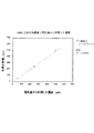
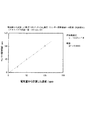
[校正用標準ガス発生器のガス発生効率(電流効率)]
供給する電気量(電解電流値×時間)を基にしてファラデーの法則から算出した二酸化塩素ガス濃度(理論値)と、実際に生成した二酸化塩素ガスのヨウ素デンプン反応滴定による化学分析値(実測値)との関係を表1、図7に示す。
[Gas generation efficiency (current efficiency) of standard calibration gas generator]
Chlorine dioxide gas concentration (theoretical value) calculated from Faraday's law based on the amount of electricity supplied (electrolytic current value x time) and chemical analysis value (actual measurement value) by iodine-starch reaction titration of actually generated chlorine dioxide gas ) Are shown in Table 1 and FIG.

[二酸化塩素濃度測定器での二酸化塩素濃度の濃度測定]
対極が直径8mm長さ50mmの円筒形Ag電極、作用電極が直径1.0mmの円盤形Pt電極であり、対極と電解液との接触面積が動作電極と電解液との接触面積の1600倍である、図1に示す2電極式・定電位電解二酸化塩素濃度測定器を用いて、二酸化塩素ガス発生装置で発生させた二酸化塩素ガスの濃度を測定した。
[Measurement of chlorine dioxide concentration with a chlorine dioxide concentration measuring device]
The counter electrode is a cylindrical Ag electrode with a diameter of 8 mm and a length of 50 mm, and the working electrode is a disk-shaped Pt electrode with a diameter of 1.0 mm. The contact area between the counter electrode and the electrolytic solution is 1600 times the contact area between the operating electrode and the electrolytic solution. The concentration of chlorine dioxide gas generated by the chlorine dioxide gas generator was measured using a two-electrode constant-potential electrolytic chlorine dioxide concentration measuring device shown in FIG.
電解電流値が一定の条件下でキャリアガスの流量を変化させた場合に、電流量とキャリアガス流量から計算される、校正用標準ガス発生器が発生する二酸化塩素ガスの濃度と、2電極式・定電位電解二酸化塩素濃度測定器での測定値との関係を、表2、図8に示す。 When the flow rate of the carrier gas is changed under the condition that the electrolytic current value is constant, the concentration of chlorine dioxide gas generated by the standard gas generator for calibration calculated from the current amount and the carrier gas flow rate, and the 2-electrode type -Tables 2 and 8 show the relationship with the values measured by the constant potential electrolytic chlorine dioxide concentration measuring device.
また、キャリアガス(空気)の供給量が一定の条件下で、電解電流値を変化させた場合に、電流量とキャリアガス流量から計算される、校正用標準ガス発生器が発生する二酸化塩素ガスの濃度と、2電極式・定電位電解二酸化塩素濃度測定器での測定値との関係を表3、図9に示す。 Chlorine dioxide gas generated by the calibration standard gas generator, which is calculated from the current amount and the carrier gas flow rate when the electrolytic current value is changed under the condition that the carrier gas (air) supply amount is constant. The relationship between the concentration of the gas and the value measured by the two-electrode type constant potential electrolytic chlorine dioxide concentration measuring device is shown in Tables 3 and 9.
1 校正用標準ガス発生器
10 ガス発生電極
11 ガス通過性ガス発生電極
12 ガス発生電極リード
13 キャリアガス入口
14 標準ガス出口
20 対電極
21 対電極板
22 対電極リード
23 対電極ガス出口
30 電解液
30f 液面
40 電解液槽
50 電解液導通部材
51 脚部
51p 保護管
52 頂面(保液部)
60 ガス発生室
70 液相蓋
70b 底部
71 気相蓋
80 Oリング
100 2電極式・定電位電解二酸化塩素濃度測定器
110 センサヘッド部
111 容器
112 ガス透過膜
120 対極
130 作用電極
131 導線
132 絶縁体
140 電解液(電解質溶液)
150 電位規制部
1 Standard gas generator for
60
120
150 Potential control unit
Claims (3)
上記作用電極の電位を規制する定電圧電源部と、
上記作用電極を流れる電流値を検出する電流検出部と、を備える2電極式定電位電解二酸化塩素濃度測定器であって、
上記電解液が、塩化物イオン(Cl−)を含み、
上記対極が、上記電解液との接触面積が上記作用電極と上記電解液との接触面積の100倍以上である参照電極を兼ねたAgCl/Ag系の電極であり、
上記作用電極の電位を二酸化塩素の還元反応の限界拡散電流の範囲内で一定に保ち、定電位電解することを特徴とする2電極式・定電位電解二酸化塩素濃度測定器。 A sensor head unit having an electrolytic solution, a counter electrode, and a working electrode in a container having a gas permeable membrane,
A constant voltage power supply that regulates the potential of the working electrode,
A two-electrode constant-potential electrolytic chlorine dioxide concentration measuring device including a current detection unit that detects a current value flowing through the working electrode.
The above electrolyte contains chloride ion (Cl − ) and contains
The counter electrode is an AgCl / Ag-based electrode that also serves as a reference electrode whose contact area with the electrolytic solution is 100 times or more the contact area between the working electrode and the electrolytic solution.
A two-electrode, constant-potential electrolysis chlorine dioxide concentration measuring device characterized in that the potential of the working electrode is kept constant within the limit diffusion current of the reduction reaction of chlorine dioxide and constant-potential electrolysis is performed.
上記校正用標準ガス発生器が、
ガス通過性を有するガス発生電極と、
上記ガス発生電極と逆極性の対電極と、
上記両電極間に直流電流を印加する定電流電源部と、
NaClO2およびNaClを含む電解液と、
上記電解液を貯留する電解液槽と、
上記電解液槽からの電解液を上記ガス発生電極に導く電解液導通部材と、を備えるものであり、
上記対電極が上記電解液に接触する一方で、上記ガス発生電極の一方の面が上記電解液導通部材に導かれた電解液に接触し他方の面が気相に部分的に露出しており、
上記直流電流と、発生した二酸化塩素ガスを運ぶキャリアガスの流量とで二酸化塩素の濃度を制御することを特徴とする請求項1に記載の2電極式・定電位電解二酸化塩素濃度測定器。 In addition, it is equipped with a standard gas generator for calibration.
The above standard gas generator for calibration
Gas generating electrodes with gas permeability and
A counter electrode having the opposite polarity to the gas generating electrode,
A constant current power supply unit that applies a direct current between the two electrodes,
An electrolytic solution containing NaClO 2 and NaCl,
An electrolyte tank for storing the electrolyte and
It includes an electrolytic solution conducting member that guides the electrolytic solution from the electrolytic solution tank to the gas generating electrode.
While the counter electrode is in contact with the electrolytic solution, one surface of the gas generating electrode is in contact with the electrolytic solution guided to the electrolytic solution conductive member, and the other surface is partially exposed to the gas phase. ,
The two-electrode constant-potential electrolytic chlorine dioxide concentration measuring device according to claim 1, wherein the chlorine dioxide concentration is controlled by the direct current and the flow rate of the carrier gas carrying the generated chlorine dioxide gas.
上記電流波形が、通電初期に大電流を流した後に級数的に減少させ、その後一定であることを特徴とする請求項2に記載の2電極式・定電位電解二酸化塩素濃度測定器。 The constant current power supply unit is a programmable current regulation power supply that can change the current waveform.
The two-electrode constant-potential electrolytic chlorine dioxide concentration measuring device according to claim 2, wherein the current waveform is serially reduced after a large current is applied at the initial stage of energization, and then is constant.
Priority Applications (1)
| Application Number | Priority Date | Filing Date | Title |
|---|---|---|---|
| JP2017204641A JP6861416B2 (en) | 2017-10-23 | 2017-10-23 | Chlorine dioxide gas concentration measuring instrument |
Applications Claiming Priority (1)
| Application Number | Priority Date | Filing Date | Title |
|---|---|---|---|
| JP2017204641A JP6861416B2 (en) | 2017-10-23 | 2017-10-23 | Chlorine dioxide gas concentration measuring instrument |
Publications (2)
| Publication Number | Publication Date |
|---|---|
| JP2019078594A JP2019078594A (en) | 2019-05-23 |
| JP6861416B2 true JP6861416B2 (en) | 2021-04-21 |
Family
ID=66628407
Family Applications (1)
| Application Number | Title | Priority Date | Filing Date |
|---|---|---|---|
| JP2017204641A Active JP6861416B2 (en) | 2017-10-23 | 2017-10-23 | Chlorine dioxide gas concentration measuring instrument |
Country Status (1)
| Country | Link |
|---|---|
| JP (1) | JP6861416B2 (en) |
Families Citing this family (1)
| Publication number | Priority date | Publication date | Assignee | Title |
|---|---|---|---|---|
| KR102244024B1 (en) * | 2019-08-23 | 2021-04-23 | 국방과학연구소 | Ion sensing system with adjustable sensitivity based on multilayer structure |
Family Cites Families (12)
| Publication number | Priority date | Publication date | Assignee | Title |
|---|---|---|---|---|
| DE2930074C2 (en) * | 1979-07-25 | 1983-11-17 | Fresenius AG, 6380 Bad Homburg | Measuring device for determining the partial pressure of oxygen in liquids and gases |
| JPH0224552A (en) * | 1988-07-12 | 1990-01-26 | Kikuo Oikawa | Quantifying method of chlorine dioxide |
| JPH0746090B2 (en) * | 1989-05-10 | 1995-05-17 | 東亜電波工業株式会社 | Method for measuring dissolved chlorine dioxide |
| JPH0769299B2 (en) * | 1989-06-05 | 1995-07-26 | 東亜電波工業株式会社 | Chlorine dioxide measuring device |
| JPH0769287B2 (en) * | 1990-03-23 | 1995-07-26 | 東亜電波工業株式会社 | Calibration method for oxidizing gas measuring device |
| GB9302838D0 (en) * | 1993-02-12 | 1993-03-31 | City Tech | Gas generating apparatus |
| JP3076175B2 (en) * | 1993-07-02 | 2000-08-14 | 株式会社ナカボーテック | Silver / silver chloride reference electrode and method for producing the same |
| DE19547670A1 (en) * | 1995-12-20 | 1997-06-26 | Prominent Dosiertechnik Gmbh | Amperometric two-electrode sensor, especially for hydrogen peroxide |
| US6300108B1 (en) * | 1999-07-21 | 2001-10-09 | The Regents Of The University Of California | Controlled electroporation and mass transfer across cell membranes |
| JP2004069582A (en) * | 2002-08-08 | 2004-03-04 | Matsushita Electric Ind Co Ltd | Biosensor |
| JP3838435B2 (en) * | 2003-06-25 | 2006-10-25 | 明胤 秋山 | Hypochlorous acid concentration measuring device |
| US20070045128A1 (en) * | 2005-08-19 | 2007-03-01 | Honeywell International Inc. | Chlorine dioxide sensor |
-
2017
- 2017-10-23 JP JP2017204641A patent/JP6861416B2/en active Active
Also Published As
| Publication number | Publication date |
|---|---|
| JP2019078594A (en) | 2019-05-23 |
Similar Documents
| Publication | Publication Date | Title |
|---|---|---|
| US11913903B1 (en) | Systems and methods for testing and measuring compounds | |
| Vos et al. | Measurement of competition between oxygen evolution and chlorine evolution using rotating ring-disk electrode voltammetry | |
| US9625405B2 (en) | Ozone water concentration measurement apparatus and ozone water concentration measurement method | |
| US20030205465A1 (en) | Chloramine amperometric sensor | |
| EP0656112A1 (en) | Chlorine sensor | |
| JP6861416B2 (en) | Chlorine dioxide gas concentration measuring instrument | |
| US5334295A (en) | Micro fuel-cell oxygen gas sensor | |
| WO2015060328A1 (en) | Potentiostatic electrolytic gas sensor | |
| AU2005285460B2 (en) | Free chlorine sensor | |
| JP5710345B2 (en) | Method for measuring total concentration of oxidizing substance, concentration meter for measuring total concentration of oxidizing substance, and sulfuric acid electrolysis apparatus using the same | |
| JP6426336B2 (en) | Constant potential electrolysis type gas sensor | |
| JPH10311815A (en) | Deterioration determination method and calibration method for electrochemical carbon monoxide gas sensor | |
| JP2011007508A (en) | Method for measuring concentration of free residual chlorine, and method for generating hypochlorous acid using the same | |
| US5393392A (en) | Polarographic PPB oxygen gas sensor | |
| CN110579524A (en) | Method for cleaning, adjusting, calibrating and/or adjusting a current sensor | |
| JP2014098679A (en) | Controlled-potential-electrolysis type gas sensor | |
| JP2012117954A (en) | Hydrogen fluoride detector | |
| JP6820550B2 (en) | Gas generator | |
| JP5212306B2 (en) | Diaphragm electrochemical sensor | |
| JP2005062133A (en) | Residual chlorine concentration measuring device | |
| JP2020085877A (en) | Constant potential electrolysis gas sensor | |
| JP3443230B2 (en) | Trace oxygen concentration measurement device | |
| RU2178886C2 (en) | Method and apparatus for detecting concentration of active chlorine in electrolyte solution | |
| JP2026055260A (en) | Residual chlorine measuring device, residual chlorine measuring method, and composite sensor for residual chlorine measuring | |
| CN121263215A (en) | Space purification system |
Legal Events
| Date | Code | Title | Description |
|---|---|---|---|
| A521 | Request for written amendment filed |
Free format text: JAPANESE INTERMEDIATE CODE: A523 Effective date: 20171024 |
|
| A80 | Written request to apply exceptions to lack of novelty of invention |
Free format text: JAPANESE INTERMEDIATE CODE: A80 Effective date: 20171024 |
|
| A621 | Written request for application examination |
Free format text: JAPANESE INTERMEDIATE CODE: A621 Effective date: 20200122 |
|
| A977 | Report on retrieval |
Free format text: JAPANESE INTERMEDIATE CODE: A971007 Effective date: 20201216 |
|
| A131 | Notification of reasons for refusal |
Free format text: JAPANESE INTERMEDIATE CODE: A131 Effective date: 20210106 |
|
| TRDD | Decision of grant or rejection written | ||
| A01 | Written decision to grant a patent or to grant a registration (utility model) |
Free format text: JAPANESE INTERMEDIATE CODE: A01 Effective date: 20210315 |
|
| A61 | First payment of annual fees (during grant procedure) |
Free format text: JAPANESE INTERMEDIATE CODE: A61 Effective date: 20210322 |
|
| R150 | Certificate of patent or registration of utility model |
Ref document number: 6861416 Country of ref document: JP Free format text: JAPANESE INTERMEDIATE CODE: R150 |
|
| R250 | Receipt of annual fees |
Free format text: JAPANESE INTERMEDIATE CODE: R250 |
|
| R250 | Receipt of annual fees |
Free format text: JAPANESE INTERMEDIATE CODE: R250 |