JP6850096B2 - Manufacturing method of semiconductor devices and manufacturing method of electronic devices - Google Patents
Manufacturing method of semiconductor devices and manufacturing method of electronic devices Download PDFInfo
- Publication number
- JP6850096B2 JP6850096B2 JP2016181423A JP2016181423A JP6850096B2 JP 6850096 B2 JP6850096 B2 JP 6850096B2 JP 2016181423 A JP2016181423 A JP 2016181423A JP 2016181423 A JP2016181423 A JP 2016181423A JP 6850096 B2 JP6850096 B2 JP 6850096B2
- Authority
- JP
- Japan
- Prior art keywords
- layer
- transistor
- oxide
- insulating layer
- semiconductor
- Prior art date
- Legal status (The legal status is an assumption and is not a legal conclusion. Google has not performed a legal analysis and makes no representation as to the accuracy of the status listed.)
- Active
Links
- 239000004065 semiconductor Substances 0.000 title claims description 337
- 238000004519 manufacturing process Methods 0.000 title claims description 79
- 238000000034 method Methods 0.000 claims description 158
- 238000010438 heat treatment Methods 0.000 claims description 56
- PXHVJJICTQNCMI-UHFFFAOYSA-N Nickel Chemical compound [Ni] PXHVJJICTQNCMI-UHFFFAOYSA-N 0.000 claims description 39
- BASFCYQUMIYNBI-UHFFFAOYSA-N platinum Chemical compound [Pt] BASFCYQUMIYNBI-UHFFFAOYSA-N 0.000 claims description 26
- 239000010936 titanium Substances 0.000 claims description 21
- 229910052782 aluminium Inorganic materials 0.000 claims description 20
- XAGFODPZIPBFFR-UHFFFAOYSA-N aluminium Chemical compound [Al] XAGFODPZIPBFFR-UHFFFAOYSA-N 0.000 claims description 20
- GUVRBAGPIYLISA-UHFFFAOYSA-N tantalum atom Chemical compound [Ta] GUVRBAGPIYLISA-UHFFFAOYSA-N 0.000 claims description 20
- 229910052759 nickel Inorganic materials 0.000 claims description 19
- 229910052715 tantalum Inorganic materials 0.000 claims description 19
- WFKWXMTUELFFGS-UHFFFAOYSA-N tungsten Chemical compound [W] WFKWXMTUELFFGS-UHFFFAOYSA-N 0.000 claims description 19
- 229910052721 tungsten Inorganic materials 0.000 claims description 19
- 239000010937 tungsten Substances 0.000 claims description 19
- ZOKXTWBITQBERF-UHFFFAOYSA-N Molybdenum Chemical compound [Mo] ZOKXTWBITQBERF-UHFFFAOYSA-N 0.000 claims description 18
- RTAQQCXQSZGOHL-UHFFFAOYSA-N Titanium Chemical compound [Ti] RTAQQCXQSZGOHL-UHFFFAOYSA-N 0.000 claims description 18
- 229910052750 molybdenum Inorganic materials 0.000 claims description 18
- 239000011733 molybdenum Substances 0.000 claims description 18
- 229910052719 titanium Inorganic materials 0.000 claims description 18
- 229910017052 cobalt Inorganic materials 0.000 claims description 14
- 239000010941 cobalt Substances 0.000 claims description 14
- GUTLYIVDDKVIGB-UHFFFAOYSA-N cobalt atom Chemical compound [Co] GUTLYIVDDKVIGB-UHFFFAOYSA-N 0.000 claims description 14
- 229910052697 platinum Inorganic materials 0.000 claims description 13
- 239000010410 layer Substances 0.000 description 1085
- 239000010408 film Substances 0.000 description 115
- 239000000758 substrate Substances 0.000 description 108
- 239000013078 crystal Substances 0.000 description 76
- 230000006870 function Effects 0.000 description 65
- 229910052760 oxygen Inorganic materials 0.000 description 56
- 239000012212 insulator Substances 0.000 description 55
- 239000001301 oxygen Substances 0.000 description 54
- 239000011701 zinc Substances 0.000 description 52
- QVGXLLKOCUKJST-UHFFFAOYSA-N atomic oxygen Chemical compound [O] QVGXLLKOCUKJST-UHFFFAOYSA-N 0.000 description 51
- IJGRMHOSHXDMSA-UHFFFAOYSA-N Atomic nitrogen Chemical compound N#N IJGRMHOSHXDMSA-UHFFFAOYSA-N 0.000 description 47
- XUIMIQQOPSSXEZ-UHFFFAOYSA-N Silicon Chemical compound [Si] XUIMIQQOPSSXEZ-UHFFFAOYSA-N 0.000 description 44
- 229910052710 silicon Inorganic materials 0.000 description 44
- 239000010703 silicon Substances 0.000 description 44
- 238000003860 storage Methods 0.000 description 41
- 229910052739 hydrogen Inorganic materials 0.000 description 39
- 230000002829 reductive effect Effects 0.000 description 39
- 239000001257 hydrogen Substances 0.000 description 38
- 239000000463 material Substances 0.000 description 38
- 230000002093 peripheral effect Effects 0.000 description 34
- 239000004973 liquid crystal related substance Substances 0.000 description 32
- 238000000231 atomic layer deposition Methods 0.000 description 31
- UFHFLCQGNIYNRP-UHFFFAOYSA-N Hydrogen Chemical compound [H][H] UFHFLCQGNIYNRP-UHFFFAOYSA-N 0.000 description 30
- 238000010586 diagram Methods 0.000 description 27
- 230000015572 biosynthetic process Effects 0.000 description 26
- 239000012535 impurity Substances 0.000 description 25
- 125000004429 atom Chemical group 0.000 description 24
- 229910052738 indium Inorganic materials 0.000 description 23
- APFVFJFRJDLVQX-UHFFFAOYSA-N indium atom Chemical compound [In] APFVFJFRJDLVQX-UHFFFAOYSA-N 0.000 description 23
- 229910052757 nitrogen Inorganic materials 0.000 description 23
- 238000006243 chemical reaction Methods 0.000 description 22
- 238000005229 chemical vapour deposition Methods 0.000 description 22
- 238000009413 insulation Methods 0.000 description 22
- 150000002500 ions Chemical class 0.000 description 22
- 206010021143 Hypoxia Diseases 0.000 description 20
- 239000007789 gas Substances 0.000 description 20
- 239000008188 pellet Substances 0.000 description 19
- 238000004544 sputter deposition Methods 0.000 description 19
- 230000007547 defect Effects 0.000 description 18
- 239000000523 sample Substances 0.000 description 18
- HCHKCACWOHOZIP-UHFFFAOYSA-N Zinc Chemical compound [Zn] HCHKCACWOHOZIP-UHFFFAOYSA-N 0.000 description 17
- 229910052725 zinc Inorganic materials 0.000 description 17
- 229910000449 hafnium oxide Inorganic materials 0.000 description 16
- WIHZLLGSGQNAGK-UHFFFAOYSA-N hafnium(4+);oxygen(2-) Chemical compound [O-2].[O-2].[Hf+4] WIHZLLGSGQNAGK-UHFFFAOYSA-N 0.000 description 16
- 229910052751 metal Inorganic materials 0.000 description 15
- 210000004027 cell Anatomy 0.000 description 14
- 239000002184 metal Substances 0.000 description 14
- 239000000203 mixture Substances 0.000 description 14
- 239000002243 precursor Substances 0.000 description 13
- 238000011282 treatment Methods 0.000 description 13
- XKRFYHLGVUSROY-UHFFFAOYSA-N Argon Chemical compound [Ar] XKRFYHLGVUSROY-UHFFFAOYSA-N 0.000 description 12
- 239000012298 atmosphere Substances 0.000 description 12
- 239000004020 conductor Substances 0.000 description 12
- 238000002173 high-resolution transmission electron microscopy Methods 0.000 description 12
- -1 or the like Substances 0.000 description 12
- 238000003917 TEM image Methods 0.000 description 11
- 239000012790 adhesive layer Substances 0.000 description 11
- 230000008569 process Effects 0.000 description 11
- 238000004549 pulsed laser deposition Methods 0.000 description 11
- GYHNNYVSQQEPJS-UHFFFAOYSA-N Gallium Chemical compound [Ga] GYHNNYVSQQEPJS-UHFFFAOYSA-N 0.000 description 10
- 230000008859 change Effects 0.000 description 10
- 238000010894 electron beam technology Methods 0.000 description 10
- 229910052733 gallium Inorganic materials 0.000 description 10
- 230000004048 modification Effects 0.000 description 9
- 238000012986 modification Methods 0.000 description 9
- 238000001451 molecular beam epitaxy Methods 0.000 description 9
- 230000003071 parasitic effect Effects 0.000 description 9
- 238000009832 plasma treatment Methods 0.000 description 9
- VYPSYNLAJGMNEJ-UHFFFAOYSA-N silicon dioxide Inorganic materials O=[Si]=O VYPSYNLAJGMNEJ-UHFFFAOYSA-N 0.000 description 9
- 229910052814 silicon oxide Inorganic materials 0.000 description 9
- XEEYBQQBJWHFJM-UHFFFAOYSA-N Iron Chemical compound [Fe] XEEYBQQBJWHFJM-UHFFFAOYSA-N 0.000 description 8
- 238000004891 communication Methods 0.000 description 8
- 229910052732 germanium Inorganic materials 0.000 description 8
- GNPVGFCGXDBREM-UHFFFAOYSA-N germanium atom Chemical compound [Ge] GNPVGFCGXDBREM-UHFFFAOYSA-N 0.000 description 8
- 150000002431 hydrogen Chemical class 0.000 description 8
- 239000002159 nanocrystal Substances 0.000 description 8
- YCKRFDGAMUMZLT-UHFFFAOYSA-N Fluorine atom Chemical compound [F] YCKRFDGAMUMZLT-UHFFFAOYSA-N 0.000 description 7
- 229910052581 Si3N4 Inorganic materials 0.000 description 7
- 238000011276 addition treatment Methods 0.000 description 7
- 229910052786 argon Inorganic materials 0.000 description 7
- 230000003139 buffering effect Effects 0.000 description 7
- 238000010168 coupling process Methods 0.000 description 7
- 230000006378 damage Effects 0.000 description 7
- 229910052731 fluorine Inorganic materials 0.000 description 7
- 239000011737 fluorine Substances 0.000 description 7
- 238000005468 ion implantation Methods 0.000 description 7
- 238000002156 mixing Methods 0.000 description 7
- 230000003287 optical effect Effects 0.000 description 7
- 238000012545 processing Methods 0.000 description 7
- 239000002994 raw material Substances 0.000 description 7
- ZOXJGFHDIHLPTG-UHFFFAOYSA-N Boron Chemical compound [B] ZOXJGFHDIHLPTG-UHFFFAOYSA-N 0.000 description 6
- OKTJSMMVPCPJKN-UHFFFAOYSA-N Carbon Chemical compound [C] OKTJSMMVPCPJKN-UHFFFAOYSA-N 0.000 description 6
- 229910052784 alkaline earth metal Inorganic materials 0.000 description 6
- 238000004458 analytical method Methods 0.000 description 6
- 230000005540 biological transmission Effects 0.000 description 6
- 229910052796 boron Inorganic materials 0.000 description 6
- 230000008878 coupling Effects 0.000 description 6
- 238000005859 coupling reaction Methods 0.000 description 6
- 230000000694 effects Effects 0.000 description 6
- 238000002524 electron diffraction data Methods 0.000 description 6
- 238000005530 etching Methods 0.000 description 6
- 229910052735 hafnium Inorganic materials 0.000 description 6
- VBJZVLUMGGDVMO-UHFFFAOYSA-N hafnium atom Chemical compound [Hf] VBJZVLUMGGDVMO-UHFFFAOYSA-N 0.000 description 6
- 238000003384 imaging method Methods 0.000 description 6
- 230000001681 protective effect Effects 0.000 description 6
- 239000011347 resin Substances 0.000 description 6
- 229920005989 resin Polymers 0.000 description 6
- 230000000717 retained effect Effects 0.000 description 6
- HQVNEWCFYHHQES-UHFFFAOYSA-N silicon nitride Chemical compound N12[Si]34N5[Si]62N3[Si]51N64 HQVNEWCFYHHQES-UHFFFAOYSA-N 0.000 description 6
- 238000002230 thermal chemical vapour deposition Methods 0.000 description 6
- 229910052783 alkali metal Inorganic materials 0.000 description 5
- 150000001340 alkali metals Chemical class 0.000 description 5
- 150000001342 alkaline earth metals Chemical class 0.000 description 5
- 229910052799 carbon Inorganic materials 0.000 description 5
- 239000000969 carrier Substances 0.000 description 5
- 238000009792 diffusion process Methods 0.000 description 5
- 239000011521 glass Substances 0.000 description 5
- 229910052734 helium Inorganic materials 0.000 description 5
- 239000011261 inert gas Substances 0.000 description 5
- 229910052743 krypton Inorganic materials 0.000 description 5
- 239000012528 membrane Substances 0.000 description 5
- TWNQGVIAIRXVLR-UHFFFAOYSA-N oxo(oxoalumanyloxy)alumane Chemical compound O=[Al]O[Al]=O TWNQGVIAIRXVLR-UHFFFAOYSA-N 0.000 description 5
- 239000000047 product Substances 0.000 description 5
- VSZWPYCFIRKVQL-UHFFFAOYSA-N selanylidenegallium;selenium Chemical compound [Se].[Se]=[Ga].[Se]=[Ga] VSZWPYCFIRKVQL-UHFFFAOYSA-N 0.000 description 5
- 238000012916 structural analysis Methods 0.000 description 5
- 239000000126 substance Substances 0.000 description 5
- XLYOFNOQVPJJNP-UHFFFAOYSA-N water Substances O XLYOFNOQVPJJNP-UHFFFAOYSA-N 0.000 description 5
- 229910001868 water Inorganic materials 0.000 description 5
- JBRZTFJDHDCESZ-UHFFFAOYSA-N AsGa Chemical compound [As]#[Ga] JBRZTFJDHDCESZ-UHFFFAOYSA-N 0.000 description 4
- 229910001218 Gallium arsenide Inorganic materials 0.000 description 4
- 229910052779 Neodymium Inorganic materials 0.000 description 4
- OAICVXFJPJFONN-UHFFFAOYSA-N Phosphorus Chemical compound [P] OAICVXFJPJFONN-UHFFFAOYSA-N 0.000 description 4
- 229910045601 alloy Inorganic materials 0.000 description 4
- 239000000956 alloy Substances 0.000 description 4
- 238000005275 alloying Methods 0.000 description 4
- 229910021417 amorphous silicon Inorganic materials 0.000 description 4
- 239000011651 chromium Substances 0.000 description 4
- 230000001186 cumulative effect Effects 0.000 description 4
- 230000006866 deterioration Effects 0.000 description 4
- 238000007667 floating Methods 0.000 description 4
- 239000001307 helium Substances 0.000 description 4
- SWQJXJOGLNCZEY-UHFFFAOYSA-N helium atom Chemical compound [He] SWQJXJOGLNCZEY-UHFFFAOYSA-N 0.000 description 4
- 238000001095 inductively coupled plasma mass spectrometry Methods 0.000 description 4
- 229910052742 iron Inorganic materials 0.000 description 4
- DNNSSWSSYDEUBZ-UHFFFAOYSA-N krypton atom Chemical compound [Kr] DNNSSWSSYDEUBZ-UHFFFAOYSA-N 0.000 description 4
- 229910052746 lanthanum Inorganic materials 0.000 description 4
- FZLIPJUXYLNCLC-UHFFFAOYSA-N lanthanum atom Chemical compound [La] FZLIPJUXYLNCLC-UHFFFAOYSA-N 0.000 description 4
- 239000011777 magnesium Substances 0.000 description 4
- QEFYFXOXNSNQGX-UHFFFAOYSA-N neodymium atom Chemical compound [Nd] QEFYFXOXNSNQGX-UHFFFAOYSA-N 0.000 description 4
- 229910052754 neon Inorganic materials 0.000 description 4
- GKAOGPIIYCISHV-UHFFFAOYSA-N neon atom Chemical compound [Ne] GKAOGPIIYCISHV-UHFFFAOYSA-N 0.000 description 4
- 230000001590 oxidative effect Effects 0.000 description 4
- 229910052698 phosphorus Inorganic materials 0.000 description 4
- 239000011574 phosphorus Substances 0.000 description 4
- 238000001004 secondary ion mass spectrometry Methods 0.000 description 4
- HBMJWWWQQXIZIP-UHFFFAOYSA-N silicon carbide Chemical compound [Si+]#[C-] HBMJWWWQQXIZIP-UHFFFAOYSA-N 0.000 description 4
- 229910010271 silicon carbide Inorganic materials 0.000 description 4
- 239000002356 single layer Substances 0.000 description 4
- 239000010409 thin film Substances 0.000 description 4
- 238000005011 time of flight secondary ion mass spectroscopy Methods 0.000 description 4
- 238000002042 time-of-flight secondary ion mass spectrometry Methods 0.000 description 4
- 229910052724 xenon Inorganic materials 0.000 description 4
- FHNFHKCVQCLJFQ-UHFFFAOYSA-N xenon atom Chemical compound [Xe] FHNFHKCVQCLJFQ-UHFFFAOYSA-N 0.000 description 4
- 229910052727 yttrium Inorganic materials 0.000 description 4
- VWQVUPCCIRVNHF-UHFFFAOYSA-N yttrium atom Chemical compound [Y] VWQVUPCCIRVNHF-UHFFFAOYSA-N 0.000 description 4
- 229910002601 GaN Inorganic materials 0.000 description 3
- JMASRVWKEDWRBT-UHFFFAOYSA-N Gallium nitride Chemical compound [Ga]#N JMASRVWKEDWRBT-UHFFFAOYSA-N 0.000 description 3
- MHAJPDPJQMAIIY-UHFFFAOYSA-N Hydrogen peroxide Chemical compound OO MHAJPDPJQMAIIY-UHFFFAOYSA-N 0.000 description 3
- HBBGRARXTFLTSG-UHFFFAOYSA-N Lithium ion Chemical compound [Li+] HBBGRARXTFLTSG-UHFFFAOYSA-N 0.000 description 3
- FYYHWMGAXLPEAU-UHFFFAOYSA-N Magnesium Chemical compound [Mg] FYYHWMGAXLPEAU-UHFFFAOYSA-N 0.000 description 3
- 229910000577 Silicon-germanium Inorganic materials 0.000 description 3
- LEVVHYCKPQWKOP-UHFFFAOYSA-N [Si].[Ge] Chemical compound [Si].[Ge] LEVVHYCKPQWKOP-UHFFFAOYSA-N 0.000 description 3
- 230000001133 acceleration Effects 0.000 description 3
- 230000009471 action Effects 0.000 description 3
- 230000004075 alteration Effects 0.000 description 3
- 239000007795 chemical reaction product Substances 0.000 description 3
- 239000010949 copper Substances 0.000 description 3
- 238000013461 design Methods 0.000 description 3
- AJNVQOSZGJRYEI-UHFFFAOYSA-N digallium;oxygen(2-) Chemical compound [O-2].[O-2].[O-2].[Ga+3].[Ga+3] AJNVQOSZGJRYEI-UHFFFAOYSA-N 0.000 description 3
- 238000001312 dry etching Methods 0.000 description 3
- 238000002003 electron diffraction Methods 0.000 description 3
- 201000003373 familial cold autoinflammatory syndrome 3 Diseases 0.000 description 3
- 229910001195 gallium oxide Inorganic materials 0.000 description 3
- 238000002347 injection Methods 0.000 description 3
- 239000007924 injection Substances 0.000 description 3
- 229910001416 lithium ion Inorganic materials 0.000 description 3
- 229910052749 magnesium Inorganic materials 0.000 description 3
- CPLXHLVBOLITMK-UHFFFAOYSA-N magnesium oxide Inorganic materials [Mg]=O CPLXHLVBOLITMK-UHFFFAOYSA-N 0.000 description 3
- 239000011159 matrix material Substances 0.000 description 3
- 230000007246 mechanism Effects 0.000 description 3
- 150000004767 nitrides Chemical class 0.000 description 3
- 230000003647 oxidation Effects 0.000 description 3
- 238000007254 oxidation reaction Methods 0.000 description 3
- SIWVEOZUMHYXCS-UHFFFAOYSA-N oxo(oxoyttriooxy)yttrium Chemical compound O=[Y]O[Y]=O SIWVEOZUMHYXCS-UHFFFAOYSA-N 0.000 description 3
- 238000000623 plasma-assisted chemical vapour deposition Methods 0.000 description 3
- 230000035945 sensitivity Effects 0.000 description 3
- 125000006850 spacer group Chemical group 0.000 description 3
- CURLTUGMZLYLDI-UHFFFAOYSA-N Carbon dioxide Chemical compound O=C=O CURLTUGMZLYLDI-UHFFFAOYSA-N 0.000 description 2
- 229910052684 Cerium Inorganic materials 0.000 description 2
- VYZAMTAEIAYCRO-UHFFFAOYSA-N Chromium Chemical compound [Cr] VYZAMTAEIAYCRO-UHFFFAOYSA-N 0.000 description 2
- RYGMFSIKBFXOCR-UHFFFAOYSA-N Copper Chemical compound [Cu] RYGMFSIKBFXOCR-UHFFFAOYSA-N 0.000 description 2
- WHXSMMKQMYFTQS-UHFFFAOYSA-N Lithium Chemical compound [Li] WHXSMMKQMYFTQS-UHFFFAOYSA-N 0.000 description 2
- GQPLMRYTRLFLPF-UHFFFAOYSA-N Nitrous Oxide Chemical compound [O-][N+]#N GQPLMRYTRLFLPF-UHFFFAOYSA-N 0.000 description 2
- BUGBHKTXTAQXES-UHFFFAOYSA-N Selenium Chemical compound [Se] BUGBHKTXTAQXES-UHFFFAOYSA-N 0.000 description 2
- QAOWNCQODCNURD-UHFFFAOYSA-N Sulfuric acid Chemical compound OS(O)(=O)=O QAOWNCQODCNURD-UHFFFAOYSA-N 0.000 description 2
- ATJFFYVFTNAWJD-UHFFFAOYSA-N Tin Chemical compound [Sn] ATJFFYVFTNAWJD-UHFFFAOYSA-N 0.000 description 2
- 238000002441 X-ray diffraction Methods 0.000 description 2
- QCWXUUIWCKQGHC-UHFFFAOYSA-N Zirconium Chemical compound [Zr] QCWXUUIWCKQGHC-UHFFFAOYSA-N 0.000 description 2
- 239000004760 aramid Substances 0.000 description 2
- 229920003235 aromatic polyamide Polymers 0.000 description 2
- 238000005452 bending Methods 0.000 description 2
- 230000000903 blocking effect Effects 0.000 description 2
- 210000005252 bulbus oculi Anatomy 0.000 description 2
- 229910052800 carbon group element Inorganic materials 0.000 description 2
- 239000000919 ceramic Substances 0.000 description 2
- ZMIGMASIKSOYAM-UHFFFAOYSA-N cerium Chemical compound [Ce][Ce][Ce][Ce][Ce][Ce][Ce][Ce][Ce][Ce][Ce][Ce][Ce][Ce][Ce][Ce][Ce][Ce][Ce][Ce][Ce][Ce][Ce][Ce][Ce][Ce][Ce][Ce][Ce][Ce][Ce][Ce][Ce][Ce][Ce][Ce][Ce][Ce] ZMIGMASIKSOYAM-UHFFFAOYSA-N 0.000 description 2
- 229910052804 chromium Inorganic materials 0.000 description 2
- 150000001875 compounds Chemical class 0.000 description 2
- 229910052802 copper Inorganic materials 0.000 description 2
- 238000012937 correction Methods 0.000 description 2
- 238000001514 detection method Methods 0.000 description 2
- 238000001962 electrophoresis Methods 0.000 description 2
- 230000005281 excited state Effects 0.000 description 2
- 239000000835 fiber Substances 0.000 description 2
- 238000001914 filtration Methods 0.000 description 2
- 235000013305 food Nutrition 0.000 description 2
- 230000007274 generation of a signal involved in cell-cell signaling Effects 0.000 description 2
- 210000003128 head Anatomy 0.000 description 2
- 229910001385 heavy metal Inorganic materials 0.000 description 2
- 238000007654 immersion Methods 0.000 description 2
- UJXZVRRCKFUQKG-UHFFFAOYSA-K indium(3+);phosphate Chemical compound [In+3].[O-]P([O-])([O-])=O UJXZVRRCKFUQKG-UHFFFAOYSA-K 0.000 description 2
- 238000009616 inductively coupled plasma Methods 0.000 description 2
- 239000000976 ink Substances 0.000 description 2
- 230000001788 irregular Effects 0.000 description 2
- MRELNEQAGSRDBK-UHFFFAOYSA-N lanthanum(3+);oxygen(2-) Chemical compound [O-2].[O-2].[O-2].[La+3].[La+3] MRELNEQAGSRDBK-UHFFFAOYSA-N 0.000 description 2
- 229910052744 lithium Inorganic materials 0.000 description 2
- 239000000395 magnesium oxide Substances 0.000 description 2
- 230000014759 maintenance of location Effects 0.000 description 2
- 229910021424 microcrystalline silicon Inorganic materials 0.000 description 2
- 230000005012 migration Effects 0.000 description 2
- 238000013508 migration Methods 0.000 description 2
- 239000011259 mixed solution Substances 0.000 description 2
- PLDDOISOJJCEMH-UHFFFAOYSA-N neodymium(3+);oxygen(2-) Chemical compound [O-2].[O-2].[O-2].[Nd+3].[Nd+3] PLDDOISOJJCEMH-UHFFFAOYSA-N 0.000 description 2
- 230000007935 neutral effect Effects 0.000 description 2
- 239000010955 niobium Substances 0.000 description 2
- 150000002894 organic compounds Chemical class 0.000 description 2
- 239000007800 oxidant agent Substances 0.000 description 2
- 125000004430 oxygen atom Chemical group O* 0.000 description 2
- 238000004806 packaging method and process Methods 0.000 description 2
- 239000002245 particle Substances 0.000 description 2
- 238000005192 partition Methods 0.000 description 2
- 230000000737 periodic effect Effects 0.000 description 2
- 229910052696 pnictogen Inorganic materials 0.000 description 2
- 229920000642 polymer Polymers 0.000 description 2
- 229920001343 polytetrafluoroethylene Polymers 0.000 description 2
- 239000004810 polytetrafluoroethylene Substances 0.000 description 2
- 230000005855 radiation Effects 0.000 description 2
- 239000000376 reactant Substances 0.000 description 2
- 230000009467 reduction Effects 0.000 description 2
- 230000002441 reversible effect Effects 0.000 description 2
- 229910052711 selenium Inorganic materials 0.000 description 2
- 239000011669 selenium Substances 0.000 description 2
- LIVNPJMFVYWSIS-UHFFFAOYSA-N silicon monoxide Chemical compound [Si-]#[O+] LIVNPJMFVYWSIS-UHFFFAOYSA-N 0.000 description 2
- 229910052718 tin Inorganic materials 0.000 description 2
- 229910052723 transition metal Inorganic materials 0.000 description 2
- 239000011800 void material Substances 0.000 description 2
- 238000001039 wet etching Methods 0.000 description 2
- 229910001233 yttria-stabilized zirconia Inorganic materials 0.000 description 2
- 229910052726 zirconium Inorganic materials 0.000 description 2
- WUPHOULIZUERAE-UHFFFAOYSA-N 3-(oxolan-2-yl)propanoic acid Chemical compound OC(=O)CCC1CCCO1 WUPHOULIZUERAE-UHFFFAOYSA-N 0.000 description 1
- MARUHZGHZWCEQU-UHFFFAOYSA-N 5-phenyl-2h-tetrazole Chemical compound C1=CC=CC=C1C1=NNN=N1 MARUHZGHZWCEQU-UHFFFAOYSA-N 0.000 description 1
- 210000002925 A-like Anatomy 0.000 description 1
- VHUUQVKOLVNVRT-UHFFFAOYSA-N Ammonium hydroxide Chemical compound [NH4+].[OH-] VHUUQVKOLVNVRT-UHFFFAOYSA-N 0.000 description 1
- FIPWRIJSWJWJAI-UHFFFAOYSA-N Butyl carbitol 6-propylpiperonyl ether Chemical compound C1=C(CCC)C(COCCOCCOCCCC)=CC2=C1OCO2 FIPWRIJSWJWJAI-UHFFFAOYSA-N 0.000 description 1
- 229910000925 Cd alloy Inorganic materials 0.000 description 1
- DGAQECJNVWCQMB-PUAWFVPOSA-M Ilexoside XXIX Chemical compound C[C@@H]1CC[C@@]2(CC[C@@]3(C(=CC[C@H]4[C@]3(CC[C@@H]5[C@@]4(CC[C@@H](C5(C)C)OS(=O)(=O)[O-])C)C)[C@@H]2[C@]1(C)O)C)C(=O)O[C@H]6[C@@H]([C@H]([C@@H]([C@H](O6)CO)O)O)O.[Na+] DGAQECJNVWCQMB-PUAWFVPOSA-M 0.000 description 1
- GPXJNWSHGFTCBW-UHFFFAOYSA-N Indium phosphide Chemical compound [In]#P GPXJNWSHGFTCBW-UHFFFAOYSA-N 0.000 description 1
- 241001465754 Metazoa Species 0.000 description 1
- 239000004677 Nylon Substances 0.000 description 1
- BPQQTUXANYXVAA-UHFFFAOYSA-N Orthosilicate Chemical compound [O-][Si]([O-])([O-])[O-] BPQQTUXANYXVAA-UHFFFAOYSA-N 0.000 description 1
- 239000004952 Polyamide Substances 0.000 description 1
- 239000004642 Polyimide Substances 0.000 description 1
- KJTLSVCANCCWHF-UHFFFAOYSA-N Ruthenium Chemical compound [Ru] KJTLSVCANCCWHF-UHFFFAOYSA-N 0.000 description 1
- BQCADISMDOOEFD-UHFFFAOYSA-N Silver Chemical compound [Ag] BQCADISMDOOEFD-UHFFFAOYSA-N 0.000 description 1
- 229910007541 Zn O Inorganic materials 0.000 description 1
- NIXOWILDQLNWCW-UHFFFAOYSA-N acrylic acid group Chemical group C(C=C)(=O)O NIXOWILDQLNWCW-UHFFFAOYSA-N 0.000 description 1
- FTWRSWRBSVXQPI-UHFFFAOYSA-N alumanylidynearsane;gallanylidynearsane Chemical compound [As]#[Al].[As]#[Ga] FTWRSWRBSVXQPI-UHFFFAOYSA-N 0.000 description 1
- MDPILPRLPQYEEN-UHFFFAOYSA-N aluminium arsenide Chemical compound [As]#[Al] MDPILPRLPQYEEN-UHFFFAOYSA-N 0.000 description 1
- 235000011114 ammonium hydroxide Nutrition 0.000 description 1
- 230000008901 benefit Effects 0.000 description 1
- 229910052795 boron group element Inorganic materials 0.000 description 1
- 229910052980 cadmium sulfide Inorganic materials 0.000 description 1
- CEKJAYFBQARQNG-UHFFFAOYSA-N cadmium zinc Chemical compound [Zn].[Cd] CEKJAYFBQARQNG-UHFFFAOYSA-N 0.000 description 1
- 238000004364 calculation method Methods 0.000 description 1
- 239000001569 carbon dioxide Substances 0.000 description 1
- 229910002092 carbon dioxide Inorganic materials 0.000 description 1
- 239000002041 carbon nanotube Substances 0.000 description 1
- 229910021393 carbon nanotube Inorganic materials 0.000 description 1
- 230000000295 complement effect Effects 0.000 description 1
- 239000002131 composite material Substances 0.000 description 1
- 238000012790 confirmation Methods 0.000 description 1
- 239000000470 constituent Substances 0.000 description 1
- 238000011109 contamination Methods 0.000 description 1
- PMHQVHHXPFUNSP-UHFFFAOYSA-M copper(1+);methylsulfanylmethane;bromide Chemical compound Br[Cu].CSC PMHQVHHXPFUNSP-UHFFFAOYSA-M 0.000 description 1
- 229910021419 crystalline silicon Inorganic materials 0.000 description 1
- 238000000354 decomposition reaction Methods 0.000 description 1
- 230000002950 deficient Effects 0.000 description 1
- 229910001873 dinitrogen Inorganic materials 0.000 description 1
- 239000002019 doping agent Substances 0.000 description 1
- 239000003814 drug Substances 0.000 description 1
- 229940079593 drug Drugs 0.000 description 1
- 230000005685 electric field effect Effects 0.000 description 1
- 238000005401 electroluminescence Methods 0.000 description 1
- 239000003792 electrolyte Substances 0.000 description 1
- 230000005672 electromagnetic field Effects 0.000 description 1
- 230000005674 electromagnetic induction Effects 0.000 description 1
- 238000001941 electron spectroscopy Methods 0.000 description 1
- 238000005516 engineering process Methods 0.000 description 1
- 230000005284 excitation Effects 0.000 description 1
- 239000000284 extract Substances 0.000 description 1
- 210000000744 eyelid Anatomy 0.000 description 1
- 230000005669 field effect Effects 0.000 description 1
- 150000002222 fluorine compounds Chemical class 0.000 description 1
- 239000011888 foil Substances 0.000 description 1
- YBMRDBCBODYGJE-UHFFFAOYSA-N germanium oxide Inorganic materials O=[Ge]=O YBMRDBCBODYGJE-UHFFFAOYSA-N 0.000 description 1
- 238000009499 grossing Methods 0.000 description 1
- 230000005283 ground state Effects 0.000 description 1
- XMBWDFGMSWQBCA-UHFFFAOYSA-N hydrogen iodide Chemical compound I XMBWDFGMSWQBCA-UHFFFAOYSA-N 0.000 description 1
- 238000010191 image analysis Methods 0.000 description 1
- 230000001771 impaired effect Effects 0.000 description 1
- 230000006698 induction Effects 0.000 description 1
- 229910010272 inorganic material Inorganic materials 0.000 description 1
- 239000011147 inorganic material Substances 0.000 description 1
- 238000007689 inspection Methods 0.000 description 1
- 230000010354 integration Effects 0.000 description 1
- 239000011229 interlayer Substances 0.000 description 1
- 238000005304 joining Methods 0.000 description 1
- 238000010030 laminating Methods 0.000 description 1
- 230000031700 light absorption Effects 0.000 description 1
- AXZKOIWUVFPNLO-UHFFFAOYSA-N magnesium;oxygen(2-) Chemical compound [O-2].[Mg+2] AXZKOIWUVFPNLO-UHFFFAOYSA-N 0.000 description 1
- 230000007257 malfunction Effects 0.000 description 1
- 230000000873 masking effect Effects 0.000 description 1
- 238000005259 measurement Methods 0.000 description 1
- 229940127554 medical product Drugs 0.000 description 1
- QKEOZZYXWAIQFO-UHFFFAOYSA-M mercury(1+);iodide Chemical compound [Hg]I QKEOZZYXWAIQFO-UHFFFAOYSA-M 0.000 description 1
- 239000007769 metal material Substances 0.000 description 1
- 229910044991 metal oxide Inorganic materials 0.000 description 1
- 150000004706 metal oxides Chemical class 0.000 description 1
- 238000002488 metal-organic chemical vapour deposition Methods 0.000 description 1
- 150000002739 metals Chemical class 0.000 description 1
- 238000012544 monitoring process Methods 0.000 description 1
- 229910021421 monocrystalline silicon Inorganic materials 0.000 description 1
- QELJHCBNGDEXLD-UHFFFAOYSA-N nickel zinc Chemical compound [Ni].[Zn] QELJHCBNGDEXLD-UHFFFAOYSA-N 0.000 description 1
- 229910052758 niobium Inorganic materials 0.000 description 1
- GUCVJGMIXFAOAE-UHFFFAOYSA-N niobium atom Chemical compound [Nb] GUCVJGMIXFAOAE-UHFFFAOYSA-N 0.000 description 1
- 239000001272 nitrous oxide Substances 0.000 description 1
- 229920001778 nylon Polymers 0.000 description 1
- 238000011017 operating method Methods 0.000 description 1
- 239000011368 organic material Substances 0.000 description 1
- 125000002524 organometallic group Chemical group 0.000 description 1
- 230000001151 other effect Effects 0.000 description 1
- PVADDRMAFCOOPC-UHFFFAOYSA-N oxogermanium Chemical compound [Ge]=O PVADDRMAFCOOPC-UHFFFAOYSA-N 0.000 description 1
- RVTZCBVAJQQJTK-UHFFFAOYSA-N oxygen(2-);zirconium(4+) Chemical compound [O-2].[O-2].[Zr+4] RVTZCBVAJQQJTK-UHFFFAOYSA-N 0.000 description 1
- 230000035515 penetration Effects 0.000 description 1
- 239000012466 permeate Substances 0.000 description 1
- 238000000206 photolithography Methods 0.000 description 1
- 238000005268 plasma chemical vapour deposition Methods 0.000 description 1
- 238000005498 polishing Methods 0.000 description 1
- 229920002647 polyamide Polymers 0.000 description 1
- 229920000515 polycarbonate Polymers 0.000 description 1
- 239000004417 polycarbonate Substances 0.000 description 1
- 229920000728 polyester Polymers 0.000 description 1
- 229920001721 polyimide Polymers 0.000 description 1
- 229920000098 polyolefin Polymers 0.000 description 1
- 238000003825 pressing Methods 0.000 description 1
- 238000003672 processing method Methods 0.000 description 1
- 230000009993 protective function Effects 0.000 description 1
- 239000002096 quantum dot Substances 0.000 description 1
- 239000010453 quartz Substances 0.000 description 1
- 230000004043 responsiveness Effects 0.000 description 1
- 229910052707 ruthenium Inorganic materials 0.000 description 1
- 229910052594 sapphire Inorganic materials 0.000 description 1
- 239000010980 sapphire Substances 0.000 description 1
- 229920006395 saturated elastomer Polymers 0.000 description 1
- 238000007789 sealing Methods 0.000 description 1
- 238000004098 selected area electron diffraction Methods 0.000 description 1
- SBIBMFFZSBJNJF-UHFFFAOYSA-N selenium;zinc Chemical compound [Se]=[Zn] SBIBMFFZSBJNJF-UHFFFAOYSA-N 0.000 description 1
- 229910052709 silver Inorganic materials 0.000 description 1
- 239000004332 silver Substances 0.000 description 1
- BSWGGJHLVUUXTL-UHFFFAOYSA-N silver zinc Chemical compound [Zn].[Ag] BSWGGJHLVUUXTL-UHFFFAOYSA-N 0.000 description 1
- 229910052708 sodium Inorganic materials 0.000 description 1
- 239000011734 sodium Substances 0.000 description 1
- 241000894007 species Species 0.000 description 1
- 238000006467 substitution reaction Methods 0.000 description 1
- 239000013589 supplement Substances 0.000 description 1
- JBQYATWDVHIOAR-UHFFFAOYSA-N tellanylidenegermanium Chemical compound [Te]=[Ge] JBQYATWDVHIOAR-UHFFFAOYSA-N 0.000 description 1
- 150000003624 transition metals Chemical class 0.000 description 1
- 238000002834 transmittance Methods 0.000 description 1
- 229910052720 vanadium Inorganic materials 0.000 description 1
- LEONUFNNVUYDNQ-UHFFFAOYSA-N vanadium atom Chemical compound [V] LEONUFNNVUYDNQ-UHFFFAOYSA-N 0.000 description 1
- 229910001928 zirconium oxide Inorganic materials 0.000 description 1
Images


Classifications
-
- H—ELECTRICITY
- H01—ELECTRIC ELEMENTS
- H01L—SEMICONDUCTOR DEVICES NOT COVERED BY CLASS H10
- H01L29/00—Semiconductor devices adapted for rectifying, amplifying, oscillating or switching, or capacitors or resistors with at least one potential-jump barrier or surface barrier, e.g. PN junction depletion layer or carrier concentration layer; Details of semiconductor bodies or of electrodes thereof ; Multistep manufacturing processes therefor
- H01L29/66—Types of semiconductor device ; Multistep manufacturing processes therefor
- H01L29/68—Types of semiconductor device ; Multistep manufacturing processes therefor controllable by only the electric current supplied, or only the electric potential applied, to an electrode which does not carry the current to be rectified, amplified or switched
- H01L29/76—Unipolar devices, e.g. field effect transistors
- H01L29/772—Field effect transistors
- H01L29/78—Field effect transistors with field effect produced by an insulated gate
- H01L29/786—Thin film transistors, i.e. transistors with a channel being at least partly a thin film
- H01L29/7869—Thin film transistors, i.e. transistors with a channel being at least partly a thin film having a semiconductor body comprising an oxide semiconductor material, e.g. zinc oxide, copper aluminium oxide, cadmium stannate
- H01L29/78693—Thin film transistors, i.e. transistors with a channel being at least partly a thin film having a semiconductor body comprising an oxide semiconductor material, e.g. zinc oxide, copper aluminium oxide, cadmium stannate the semiconducting oxide being amorphous
-
- H—ELECTRICITY
- H01—ELECTRIC ELEMENTS
- H01L—SEMICONDUCTOR DEVICES NOT COVERED BY CLASS H10
- H01L29/00—Semiconductor devices adapted for rectifying, amplifying, oscillating or switching, or capacitors or resistors with at least one potential-jump barrier or surface barrier, e.g. PN junction depletion layer or carrier concentration layer; Details of semiconductor bodies or of electrodes thereof ; Multistep manufacturing processes therefor
- H01L29/40—Electrodes ; Multistep manufacturing processes therefor
- H01L29/41—Electrodes ; Multistep manufacturing processes therefor characterised by their shape, relative sizes or dispositions
- H01L29/417—Electrodes ; Multistep manufacturing processes therefor characterised by their shape, relative sizes or dispositions carrying the current to be rectified, amplified or switched
- H01L29/41725—Source or drain electrodes for field effect devices
- H01L29/41733—Source or drain electrodes for field effect devices for thin film transistors with insulated gate
-
- H—ELECTRICITY
- H01—ELECTRIC ELEMENTS
- H01L—SEMICONDUCTOR DEVICES NOT COVERED BY CLASS H10
- H01L21/00—Processes or apparatus adapted for the manufacture or treatment of semiconductor or solid state devices or of parts thereof
- H01L21/02—Manufacture or treatment of semiconductor devices or of parts thereof
- H01L21/04—Manufacture or treatment of semiconductor devices or of parts thereof the devices having at least one potential-jump barrier or surface barrier, e.g. PN junction, depletion layer or carrier concentration layer
- H01L21/34—Manufacture or treatment of semiconductor devices or of parts thereof the devices having at least one potential-jump barrier or surface barrier, e.g. PN junction, depletion layer or carrier concentration layer the devices having semiconductor bodies not provided for in groups H01L21/0405, H01L21/0445, H01L21/06, H01L21/16 and H01L21/18 with or without impurities, e.g. doping materials
- H01L21/46—Treatment of semiconductor bodies using processes or apparatus not provided for in groups H01L21/428
- H01L21/477—Thermal treatment for modifying the properties of semiconductor bodies, e.g. annealing, sintering
-
- H—ELECTRICITY
- H01—ELECTRIC ELEMENTS
- H01L—SEMICONDUCTOR DEVICES NOT COVERED BY CLASS H10
- H01L27/00—Devices consisting of a plurality of semiconductor or other solid-state components formed in or on a common substrate
- H01L27/02—Devices consisting of a plurality of semiconductor or other solid-state components formed in or on a common substrate including semiconductor components specially adapted for rectifying, oscillating, amplifying or switching and having at least one potential-jump barrier or surface barrier; including integrated passive circuit elements with at least one potential-jump barrier or surface barrier
- H01L27/12—Devices consisting of a plurality of semiconductor or other solid-state components formed in or on a common substrate including semiconductor components specially adapted for rectifying, oscillating, amplifying or switching and having at least one potential-jump barrier or surface barrier; including integrated passive circuit elements with at least one potential-jump barrier or surface barrier the substrate being other than a semiconductor body, e.g. an insulating body
- H01L27/1214—Devices consisting of a plurality of semiconductor or other solid-state components formed in or on a common substrate including semiconductor components specially adapted for rectifying, oscillating, amplifying or switching and having at least one potential-jump barrier or surface barrier; including integrated passive circuit elements with at least one potential-jump barrier or surface barrier the substrate being other than a semiconductor body, e.g. an insulating body comprising a plurality of TFTs formed on a non-semiconducting substrate, e.g. driving circuits for AMLCDs
- H01L27/1222—Devices consisting of a plurality of semiconductor or other solid-state components formed in or on a common substrate including semiconductor components specially adapted for rectifying, oscillating, amplifying or switching and having at least one potential-jump barrier or surface barrier; including integrated passive circuit elements with at least one potential-jump barrier or surface barrier the substrate being other than a semiconductor body, e.g. an insulating body comprising a plurality of TFTs formed on a non-semiconducting substrate, e.g. driving circuits for AMLCDs with a particular composition, shape or crystalline structure of the active layer
- H01L27/1225—Devices consisting of a plurality of semiconductor or other solid-state components formed in or on a common substrate including semiconductor components specially adapted for rectifying, oscillating, amplifying or switching and having at least one potential-jump barrier or surface barrier; including integrated passive circuit elements with at least one potential-jump barrier or surface barrier the substrate being other than a semiconductor body, e.g. an insulating body comprising a plurality of TFTs formed on a non-semiconducting substrate, e.g. driving circuits for AMLCDs with a particular composition, shape or crystalline structure of the active layer with semiconductor materials not belonging to the group IV of the periodic table, e.g. InGaZnO
-
- H—ELECTRICITY
- H01—ELECTRIC ELEMENTS
- H01L—SEMICONDUCTOR DEVICES NOT COVERED BY CLASS H10
- H01L29/00—Semiconductor devices adapted for rectifying, amplifying, oscillating or switching, or capacitors or resistors with at least one potential-jump barrier or surface barrier, e.g. PN junction depletion layer or carrier concentration layer; Details of semiconductor bodies or of electrodes thereof ; Multistep manufacturing processes therefor
- H01L29/40—Electrodes ; Multistep manufacturing processes therefor
- H01L29/41—Electrodes ; Multistep manufacturing processes therefor characterised by their shape, relative sizes or dispositions
- H01L29/423—Electrodes ; Multistep manufacturing processes therefor characterised by their shape, relative sizes or dispositions not carrying the current to be rectified, amplified or switched
- H01L29/42312—Gate electrodes for field effect devices
- H01L29/42316—Gate electrodes for field effect devices for field-effect transistors
- H01L29/4232—Gate electrodes for field effect devices for field-effect transistors with insulated gate
- H01L29/42384—Gate electrodes for field effect devices for field-effect transistors with insulated gate for thin film field effect transistors, e.g. characterised by the thickness or the shape of the insulator or the dimensions, the shape or the lay-out of the conductor
-
- H—ELECTRICITY
- H01—ELECTRIC ELEMENTS
- H01L—SEMICONDUCTOR DEVICES NOT COVERED BY CLASS H10
- H01L29/00—Semiconductor devices adapted for rectifying, amplifying, oscillating or switching, or capacitors or resistors with at least one potential-jump barrier or surface barrier, e.g. PN junction depletion layer or carrier concentration layer; Details of semiconductor bodies or of electrodes thereof ; Multistep manufacturing processes therefor
- H01L29/40—Electrodes ; Multistep manufacturing processes therefor
- H01L29/43—Electrodes ; Multistep manufacturing processes therefor characterised by the materials of which they are formed
- H01L29/45—Ohmic electrodes
-
- H—ELECTRICITY
- H01—ELECTRIC ELEMENTS
- H01L—SEMICONDUCTOR DEVICES NOT COVERED BY CLASS H10
- H01L29/00—Semiconductor devices adapted for rectifying, amplifying, oscillating or switching, or capacitors or resistors with at least one potential-jump barrier or surface barrier, e.g. PN junction depletion layer or carrier concentration layer; Details of semiconductor bodies or of electrodes thereof ; Multistep manufacturing processes therefor
- H01L29/40—Electrodes ; Multistep manufacturing processes therefor
- H01L29/43—Electrodes ; Multistep manufacturing processes therefor characterised by the materials of which they are formed
- H01L29/49—Metal-insulator-semiconductor electrodes, e.g. gates of MOSFET
- H01L29/4908—Metal-insulator-semiconductor electrodes, e.g. gates of MOSFET for thin film semiconductor, e.g. gate of TFT
-
- H—ELECTRICITY
- H01—ELECTRIC ELEMENTS
- H01L—SEMICONDUCTOR DEVICES NOT COVERED BY CLASS H10
- H01L29/00—Semiconductor devices adapted for rectifying, amplifying, oscillating or switching, or capacitors or resistors with at least one potential-jump barrier or surface barrier, e.g. PN junction depletion layer or carrier concentration layer; Details of semiconductor bodies or of electrodes thereof ; Multistep manufacturing processes therefor
- H01L29/66—Types of semiconductor device ; Multistep manufacturing processes therefor
- H01L29/66007—Multistep manufacturing processes
- H01L29/66969—Multistep manufacturing processes of devices having semiconductor bodies not comprising group 14 or group 13/15 materials
-
- H—ELECTRICITY
- H01—ELECTRIC ELEMENTS
- H01L—SEMICONDUCTOR DEVICES NOT COVERED BY CLASS H10
- H01L29/00—Semiconductor devices adapted for rectifying, amplifying, oscillating or switching, or capacitors or resistors with at least one potential-jump barrier or surface barrier, e.g. PN junction depletion layer or carrier concentration layer; Details of semiconductor bodies or of electrodes thereof ; Multistep manufacturing processes therefor
- H01L29/66—Types of semiconductor device ; Multistep manufacturing processes therefor
- H01L29/68—Types of semiconductor device ; Multistep manufacturing processes therefor controllable by only the electric current supplied, or only the electric potential applied, to an electrode which does not carry the current to be rectified, amplified or switched
- H01L29/76—Unipolar devices, e.g. field effect transistors
- H01L29/772—Field effect transistors
- H01L29/78—Field effect transistors with field effect produced by an insulated gate
- H01L29/786—Thin film transistors, i.e. transistors with a channel being at least partly a thin film
- H01L29/78606—Thin film transistors, i.e. transistors with a channel being at least partly a thin film with supplementary region or layer in the thin film or in the insulated bulk substrate supporting it for controlling or increasing the safety of the device
- H01L29/78612—Thin film transistors, i.e. transistors with a channel being at least partly a thin film with supplementary region or layer in the thin film or in the insulated bulk substrate supporting it for controlling or increasing the safety of the device for preventing the kink- or the snapback effect, e.g. discharging the minority carriers of the channel region for preventing bipolar effect
- H01L29/78615—Thin film transistors, i.e. transistors with a channel being at least partly a thin film with supplementary region or layer in the thin film or in the insulated bulk substrate supporting it for controlling or increasing the safety of the device for preventing the kink- or the snapback effect, e.g. discharging the minority carriers of the channel region for preventing bipolar effect with a body contact
-
- H—ELECTRICITY
- H01—ELECTRIC ELEMENTS
- H01L—SEMICONDUCTOR DEVICES NOT COVERED BY CLASS H10
- H01L29/00—Semiconductor devices adapted for rectifying, amplifying, oscillating or switching, or capacitors or resistors with at least one potential-jump barrier or surface barrier, e.g. PN junction depletion layer or carrier concentration layer; Details of semiconductor bodies or of electrodes thereof ; Multistep manufacturing processes therefor
- H01L29/66—Types of semiconductor device ; Multistep manufacturing processes therefor
- H01L29/68—Types of semiconductor device ; Multistep manufacturing processes therefor controllable by only the electric current supplied, or only the electric potential applied, to an electrode which does not carry the current to be rectified, amplified or switched
- H01L29/76—Unipolar devices, e.g. field effect transistors
- H01L29/772—Field effect transistors
- H01L29/78—Field effect transistors with field effect produced by an insulated gate
- H01L29/786—Thin film transistors, i.e. transistors with a channel being at least partly a thin film
- H01L29/78645—Thin film transistors, i.e. transistors with a channel being at least partly a thin film with multiple gate
- H01L29/78648—Thin film transistors, i.e. transistors with a channel being at least partly a thin film with multiple gate arranged on opposing sides of the channel
-
- H—ELECTRICITY
- H01—ELECTRIC ELEMENTS
- H01L—SEMICONDUCTOR DEVICES NOT COVERED BY CLASS H10
- H01L29/00—Semiconductor devices adapted for rectifying, amplifying, oscillating or switching, or capacitors or resistors with at least one potential-jump barrier or surface barrier, e.g. PN junction depletion layer or carrier concentration layer; Details of semiconductor bodies or of electrodes thereof ; Multistep manufacturing processes therefor
- H01L29/66—Types of semiconductor device ; Multistep manufacturing processes therefor
- H01L29/68—Types of semiconductor device ; Multistep manufacturing processes therefor controllable by only the electric current supplied, or only the electric potential applied, to an electrode which does not carry the current to be rectified, amplified or switched
- H01L29/76—Unipolar devices, e.g. field effect transistors
- H01L29/772—Field effect transistors
- H01L29/78—Field effect transistors with field effect produced by an insulated gate
- H01L29/786—Thin film transistors, i.e. transistors with a channel being at least partly a thin film
- H01L29/7869—Thin film transistors, i.e. transistors with a channel being at least partly a thin film having a semiconductor body comprising an oxide semiconductor material, e.g. zinc oxide, copper aluminium oxide, cadmium stannate
-
- H—ELECTRICITY
- H01—ELECTRIC ELEMENTS
- H01L—SEMICONDUCTOR DEVICES NOT COVERED BY CLASS H10
- H01L29/00—Semiconductor devices adapted for rectifying, amplifying, oscillating or switching, or capacitors or resistors with at least one potential-jump barrier or surface barrier, e.g. PN junction depletion layer or carrier concentration layer; Details of semiconductor bodies or of electrodes thereof ; Multistep manufacturing processes therefor
- H01L29/66—Types of semiconductor device ; Multistep manufacturing processes therefor
- H01L29/68—Types of semiconductor device ; Multistep manufacturing processes therefor controllable by only the electric current supplied, or only the electric potential applied, to an electrode which does not carry the current to be rectified, amplified or switched
- H01L29/76—Unipolar devices, e.g. field effect transistors
- H01L29/772—Field effect transistors
- H01L29/78—Field effect transistors with field effect produced by an insulated gate
- H01L29/786—Thin film transistors, i.e. transistors with a channel being at least partly a thin film
- H01L29/78696—Thin film transistors, i.e. transistors with a channel being at least partly a thin film characterised by the structure of the channel, e.g. multichannel, transverse or longitudinal shape, length or width, doping structure, or the overlap or alignment between the channel and the gate, the source or the drain, or the contacting structure of the channel
Description
本発明は、物、方法、または、作製方法に関する。または、本発明は、プロセス、マシン、マニュファクチャ、または、組成物(コンポジション・オブ・マター)に関する。特に、本発明は、例えば、半導体装置、表示装置、発光装置、蓄電装置、撮像装置、それらの駆動方法、または、それらの作製方法に関する。特に、本発明の一態様は、半導体装置またはその作製方法に関する。 The present invention relates to a product, a method, or a manufacturing method. Alternatively, the present invention relates to a process, machine, manufacture, or composition (composition of matter). In particular, the present invention relates to, for example, a semiconductor device, a display device, a light emitting device, a power storage device, an image pickup device, a method for driving them, or a method for manufacturing them. In particular, one aspect of the present invention relates to a semiconductor device or a method for manufacturing the same.
なお、本明細書等において半導体装置とは、半導体特性を利用することで機能しうる装置全般を指す。トランジスタ、半導体回路は半導体装置の一態様である。また、記憶装置、表示装置、電子機器は、半導体装置を有する場合がある。 In the present specification and the like, the semiconductor device refers to all devices that can function by utilizing the semiconductor characteristics. Transistors and semiconductor circuits are one aspect of semiconductor devices. Further, the storage device, the display device, and the electronic device may have a semiconductor device.
絶縁表面を有する基板上に形成された半導体膜を用いてトランジスタを構成する技術が注目されている。当該トランジスタは集積回路(IC)や画像表示装置(表示装置)のような電子デバイスに広く応用されている。トランジスタに適用可能な半導体薄膜としてシリコン系半導体材料が広く知られているが、その他の材料として酸化物半導体膜が注目されている。 Attention is being paid to a technique for constructing a transistor using a semiconductor film formed on a substrate having an insulating surface. The transistor is widely applied to electronic devices such as integrated circuits (ICs) and image display devices (display devices). Silicon-based semiconductor materials are widely known as semiconductor thin films applicable to transistors, but oxide semiconductor films are attracting attention as other materials.
例えば、トランジスタの活性層として、インジウム(In)、ガリウム(Ga)、および亜鉛(Zn)を含む非晶質酸化物半導体層を用いたトランジスタが特許文献1に開示されている。
For example,
また、酸化物半導体層上に導電層を成膜し、その後加熱処理を行うことで当該酸化物半導体層の抵抗を下げた、トランジスタの作製方法が特許文献2、非特許文献にて開示されている。
Further,
トランジスタを高集積化させた半導体装置を作製していく上で、トランジスタの微細化は不可欠である。しかしながら、微細化したトランジスタにおいては、ゲート電極と、ソース電極またはドレイン電極が重なることにより形成される容量の寄与が無視できず、トランジスタの応答性が悪化する要因となる。 Miniaturization of transistors is indispensable for manufacturing semiconductor devices with highly integrated transistors. However, in a miniaturized transistor, the contribution of the capacitance formed by the overlap of the gate electrode and the source electrode or the drain electrode cannot be ignored, which causes the responsiveness of the transistor to deteriorate.
本発明の一態様は、ゲート電極と、ソース電極とが重なる領域および、ゲート電極とドレイン電極とが重なる領域を減少させ、それによって寄生容量を低減させることを目的の一つとする。 One aspect of the present invention is to reduce the region where the gate electrode and the source electrode overlap and the region where the gate electrode and the drain electrode overlap, thereby reducing the parasitic capacitance.
また、本発明の一態様は、ソース電極と、半導体層との間の接触抵抗およびドレイン電極と、半導体層との間の接触抵抗を低減させ、それによってトランジスタのオン電流の低減を抑制することを目的の一つとする。 Further, one aspect of the present invention is to reduce the contact resistance between the source electrode and the semiconductor layer and the contact resistance between the drain electrode and the semiconductor layer, thereby suppressing the reduction of the on-current of the transistor. Is one of the purposes.
また、本発明の一態様は、酸素欠損の少ない酸化物半導体層を有する半導体装置を提供することを目的の一つとする。また、本発明の一態様は、微細化した半導体装置を提供することを目的の一つとする。 Another object of the present invention is to provide a semiconductor device having an oxide semiconductor layer having few oxygen deficiencies. Another aspect of the present invention is to provide a miniaturized semiconductor device.
なお、これらの課題の記載は、他の課題の存在を妨げるものではない。なお、本発明の一態様は、これらの課題の全てを解決する必要はないものとする。なお、これら以外の課題は、明細書、図面、請求項などの記載から、自ずと明らかとなるものであり、明細書、図面、請求項などの記載から、これら以外の課題を抽出することが可能である。 The description of these issues does not prevent the existence of other issues. It should be noted that one aspect of the present invention does not need to solve all of these problems. It should be noted that the problems other than these are naturally clarified from the description of the description, drawings, claims, etc., and it is possible to extract the problems other than these from the description of the description, drawings, claims, etc. Is.
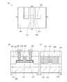
本発明の一態様は、第1の酸化物層を成膜し、第1の酸化物層を選択的に加工して第2の酸化物層を形成し、第2の酸化物層上に第1の絶縁層を成膜し、第1の絶縁層上に第1の犠牲層を成膜し、第1の絶縁層および第1の犠牲層を選択的に加工して第2の絶縁層および第2の犠牲層を形成し、第2の酸化物層、第2の絶縁層および第2の犠牲層上に導電層を成膜し、導電層を成膜した後に加熱処理を行うことにより、第2の酸化物層において、導電層と接する領域に第1の混合層を形成し、第2の犠牲層において、導電層と接する領域に第2の混合層を形成する半導体装置の作製方法であって、第1の混合層は、導電層の有する元素のうち一以上を有し、第2の混合層は、導電層の有する元素のうち一以上を有し、導電層は、アルミニウム、モリブデン、チタン、タンタル、タングステン、ニッケル、コバルトまたは白金のいずれか一以上を有し、第1の混合層の抵抗値は、第2の酸化物層の抵抗値より小さく、第2の犠牲層および第2の混合層は、ゲート電極として機能する半導体装置の作製方法である。 In one aspect of the present invention, a first oxide layer is formed, the first oxide layer is selectively processed to form a second oxide layer, and a second oxide layer is formed on the second oxide layer. The first insulating layer is formed, the first sacrificial layer is formed on the first insulating layer, and the first insulating layer and the first sacrificial layer are selectively processed to form the second insulating layer and By forming a second sacrificial layer, forming a conductive layer on the second oxide layer, the second insulating layer, and the second sacrificial layer, and then performing heat treatment after forming the conductive layer. A method for manufacturing a semiconductor device in which a first mixed layer is formed in a region in contact with a conductive layer in a second oxide layer, and a second mixed layer is formed in a region in contact with a conductive layer in a second sacrificial layer. The first mixed layer has one or more of the elements of the conductive layer, the second mixed layer has one or more of the elements of the conductive layer, and the conductive layer is aluminum or molybdenum. , Titanium, tantalum, tungsten, nickel, cobalt or platinum, the resistance value of the first mixed layer is smaller than the resistance value of the second oxide layer, and the second sacrificial layer and the second sacrificial layer. The mixed layer of 2 is a method for manufacturing a semiconductor device that functions as a gate electrode.
また、本発明の一態様は、上記構成の半導体装置の作製方法において、第2の混合層の抵抗値は、第2の犠牲層の抵抗値より小さいとより好ましい。 Further, in one aspect of the present invention, in the method for manufacturing a semiconductor device having the above configuration, it is more preferable that the resistance value of the second mixed layer is smaller than the resistance value of the second sacrificial layer.
また、本発明の一態様は、上記構成の半導体装置の作製方法において、第1の混合層および第2の混合層を形成した後に、導電層を除去するとより好ましい。 Further, in one aspect of the present invention, in the method for manufacturing a semiconductor device having the above configuration, it is more preferable to remove the conductive layer after forming the first mixed layer and the second mixed layer.
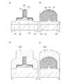
また、本発明の一態様は、第1の酸化物層を成膜し、第1の酸化物層を選択的に加工して第2の酸化物層を形成し、第2の酸化物層上に第1の絶縁層を成膜し、第1の絶縁層上に第1の犠牲層を成膜し、第1の絶縁層および第1の犠牲層を選択的に加工して第2の絶縁層および第2の犠牲層を形成し、第2の酸化物層、第2の絶縁層および第2の犠牲層上に第1の導電層を成膜し、第1の導電層を成膜した後に加熱処理を行うことにより、第2の酸化物層において、第1の導電層と接する領域に混合層を形成し、混合層および第2の犠牲層上に第3の絶縁層を成膜し、第3の絶縁層の一部を除去して第2の犠牲層の上面を露出させ、第2の犠牲層を除去し、第2の絶縁層上に第2の導電層を形成する半導体装置の作製方法であって、混合層は、第1の導電層の有する元素のうち一以上を有し、第1の導電層は、アルミニウム、モリブデン、チタン、タンタル、タングステン、ニッケル、コバルトまたは白金のいずれか一以上を有し、混合層の抵抗値は、第2の酸化物層の抵抗値より小さいことを特徴とする半導体装置の作製方法である。 Further, in one aspect of the present invention, a first oxide layer is formed, the first oxide layer is selectively processed to form a second oxide layer, and the first oxide layer is formed on the second oxide layer. A first insulating layer is formed on the surface, a first sacrificial layer is formed on the first insulating layer, and the first insulating layer and the first sacrificial layer are selectively processed to form a second insulating layer. A layer and a second sacrificial layer were formed, a first conductive layer was formed on the second oxide layer, the second insulating layer, and the second sacrificial layer, and the first conductive layer was formed. By performing a heat treatment later, a mixed layer is formed in a region in contact with the first conductive layer in the second oxide layer, and a third insulating layer is formed on the mixed layer and the second sacrificial layer. , A semiconductor device that removes a part of the third insulating layer to expose the upper surface of the second sacrificial layer, removes the second sacrificial layer, and forms a second conductive layer on the second insulating layer. The mixed layer has one or more of the elements of the first conductive layer, and the first conductive layer is made of aluminum, molybdenum, titanium, tantalum, tungsten, nickel, cobalt or platinum. A method for manufacturing a semiconductor device, which has any one or more and has a resistance value of a mixed layer smaller than a resistance value of a second oxide layer.
また、本発明の一態様は、上記構成の半導体装置の作製方法において、第2の絶縁層を介して、第2の半導体に酸素を添加するとより好ましい。 Further, in one aspect of the present invention, it is more preferable to add oxygen to the second semiconductor via the second insulating layer in the method for manufacturing the semiconductor device having the above configuration.
また、本発明の一態様は、上記各構成の半導体装置の作製方法において、第1の犠牲層は、インジウム、ガリウムまたは亜鉛のいずれか一以上を有していてもよい。また、本発明の一態様は、上記各構成の半導体装置の作製方法において、第1の犠牲層は、シリコンを有していてもよい。 Further, in one aspect of the present invention, in the method for manufacturing a semiconductor device having each of the above configurations, the first sacrificial layer may have any one or more of indium, gallium, and zinc. Further, in one aspect of the present invention, in the method for manufacturing a semiconductor device having each of the above configurations, the first sacrificial layer may have silicon.
また、本発明の一態様は、上記各構成の半導体装置の作製方法において、第2の絶縁層および第2の犠牲層を形成した後に、第2の酸化物層および第2の犠牲層上に第4の絶縁層を成膜し、第4の絶縁層を加工して、第2の絶縁層および第2の犠牲層の側面に接する第5の絶縁層を形成するとより好ましい。 Further, one aspect of the present invention is to form a second insulating layer and a second sacrificial layer on the second oxide layer and the second sacrificial layer in the method for manufacturing a semiconductor device having each of the above configurations. It is more preferable to form a fourth insulating layer and process the fourth insulating layer to form a fifth insulating layer in contact with the side surfaces of the second insulating layer and the second sacrificial layer.
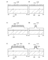
また、本発明の一態様は、第1の酸化物層を成膜し、第1の酸化物層を選択的に加工して第2の酸化物層を形成し、第2の酸化物層上に第1の導電層を成膜し、第1の導電層を成膜した後に加熱処理を行うことにより、第2の酸化物層において、第1の導電層と接する領域に混合層を形成し、混合層上に第1の絶縁層を成膜し、第1の絶縁層、混合層および第2の酸化物層の一部を除去して第3の酸化物層を形成し、第3の酸化物層上に第2の絶縁層を成膜し、第2の絶縁層上に第2の導電層を成膜する半導体装置の作製方法であって、混合層は、第1の導電層の有する元素のうち一以上を有し、第1の導電層は、アルミニウム、モリブデン、チタン、タンタル、タングステン、ニッケル、コバルトまたは白金のいずれか一以上を有し、混合層の抵抗値は、第2の酸化物層の抵抗値より小さいことを特徴とする半導体装置の作製方法である。 Further, in one aspect of the present invention, a first oxide layer is formed, the first oxide layer is selectively processed to form a second oxide layer, and the second oxide layer is formed. A first conductive layer is formed on the oxide layer, and after the first conductive layer is formed, heat treatment is performed to form a mixed layer in a region in contact with the first conductive layer in the second oxide layer. , A first insulating layer is formed on the mixed layer, and a part of the first insulating layer, the mixed layer and the second oxide layer is removed to form a third oxide layer, and a third oxide layer is formed. A method for manufacturing a semiconductor device in which a second insulating layer is formed on an oxide layer and a second conductive layer is formed on the second insulating layer. The mixed layer is a method of forming a first conductive layer. It has one or more of the elements, the first conductive layer has one or more of aluminum, molybdenum, titanium, tantalum, tungsten, nickel, cobalt or platinum, and the resistance value of the mixed layer is the second. This is a method for manufacturing a semiconductor device, which is characterized in that it is smaller than the resistance value of the oxide layer of.
また、本発明の一態様は、上記各構成の半導体装置の作製方法において、混合層を形成した後に、第1の導電層を除去するとより好ましい。 Further, in one aspect of the present invention, it is more preferable to remove the first conductive layer after forming the mixed layer in the method for manufacturing the semiconductor device having each of the above configurations.
また、本発明の一態様は、上記各構成の半導体装置の作製方法において、加熱処理は、200℃以上400℃以下で行うとより好ましい。 Further, in one aspect of the present invention, it is more preferable that the heat treatment is performed at 200 ° C. or higher and 400 ° C. or lower in the method for manufacturing the semiconductor device having each of the above configurations.
また、本発明の一態様は、半導体装置と、筐体と、表示装置またはスピーカーと、を有し、該半導体装置は、上記各構成の半導体装置の作製方法を用いて作製されている電子機器の作製方法である。 Further, one aspect of the present invention includes a semiconductor device, a housing, a display device, or a speaker, and the semiconductor device is an electronic device manufactured by using the method for manufacturing a semiconductor device having each of the above configurations. It is a manufacturing method of.
また、本発明の一態様は、酸化物層と、酸化物層上の第1の混合層と、酸化物層上の絶縁層と、絶縁層上の導電層と、導電層上の第2の混合層と、を有し、第1の混合層は、酸化物層が有する元素のうち一以上を有し、酸化物層は、インジウム、ガリウムまたは亜鉛のいずれか一以上を有し、第1の混合層または第2の混合層は、アルミニウム、モリブデン、チタン、タンタル、タングステン、ニッケル、コバルトまたは白金のいずれか一以上を有する半導体装置である。 Moreover, one aspect of the present invention is an oxide layer, a first mixed layer on the oxide layer, an insulating layer on the oxide layer, a conductive layer on the insulating layer, and a second on the conductive layer. The first mixed layer has one or more of the elements of the oxide layer, and the oxide layer has one or more of indium, gallium or zinc, and the first The mixed layer or the second mixed layer is a semiconductor device having any one or more of aluminum, molybdenum, titanium, tantalum, tungsten, nickel, cobalt and platinum.
また、本発明の一態様は、上記構成の半導体装置において、第1の混合層の抵抗値は、酸化物層の抵抗値より小さいとより好ましい。 Further, in one aspect of the present invention, in the semiconductor device having the above configuration, it is more preferable that the resistance value of the first mixed layer is smaller than the resistance value of the oxide layer.
また、本発明の一態様は、上記構成の半導体装置において、第2の混合層の抵抗値は、導電層の抵抗値より小さいとより好ましい。 Further, in one aspect of the present invention, in the semiconductor device having the above configuration, it is more preferable that the resistance value of the second mixed layer is smaller than the resistance value of the conductive layer.
また、本発明の一態様は、上記構成の半導体装置において、第2の混合層は、インジウム、ガリウムまたは亜鉛のいずれか一以上を有していてもよい。また、本発明の一態様は、上記構成の半導体装置において、第2の混合層は、シリコンを有していてもよい。 Further, in one aspect of the present invention, in the semiconductor device having the above configuration, the second mixed layer may have any one or more of indium, gallium, and zinc. Further, in one aspect of the present invention, in the semiconductor device having the above configuration, the second mixed layer may have silicon.
また、本発明の一態様は、上記構成の半導体装置と、表示素子と、を有する表示装置である。 Further, one aspect of the present invention is a display device including the semiconductor device having the above configuration and the display element.
また、本発明の一態様は、上記構成の半導体装置(第一の半導体装置)と、第二の半導体装置と、を有し、第二の半導体装置は、シリコン、ゲルマニウム、シリコンゲルマニウム、炭化シリコン、ヒ化ガリウム、ヒ化アルミニウムガリウム、リン化インジウム、窒化ガリウムまたは有機半導体のいずれか一以上を有する記憶装置である。 Further, one aspect of the present invention includes a semiconductor device (first semiconductor device) having the above configuration and a second semiconductor device, and the second semiconductor device includes silicon, germanium, silicon germanium, and silicon carbide. , A storage device having any one or more of gallium arsenide, gallium aluminum arsenide, indium phosphate, gallium nitride, or an organic semiconductor.
また、本発明の一態様は、上記構成の半導体装置と、筐体と、表示装置またはスピーカーと、を有する電子機器である。 Further, one aspect of the present invention is an electronic device having a semiconductor device having the above configuration, a housing, and a display device or a speaker.
本発明の一態様により、ゲート電極と、ソース電極とが重なる領域および、ゲート電極とドレイン電極とが重なる領域を減少させ、それによって寄生容量を低減させることができる。 According to one aspect of the present invention, the region where the gate electrode and the source electrode overlap and the region where the gate electrode and the drain electrode overlap can be reduced, thereby reducing the parasitic capacitance.
また、本発明の一態様により、ソース電極と、半導体層との間の接触抵抗およびドレイン電極と、半導体層との間の接触抵抗を低減させ、それによってトランジスタのオン電流の低減を抑制することができる。 Further, according to one aspect of the present invention, the contact resistance between the source electrode and the semiconductor layer and the contact resistance between the drain electrode and the semiconductor layer are reduced, thereby suppressing the reduction of the on-current of the transistor. Can be done.
また、本発明の一態様により、酸素欠損の少ない酸化物半導体層を有する半導体装置を提供することができる。また、本発明の一態様により、微細化した半導体装置を提供することができる。 Further, according to one aspect of the present invention, it is possible to provide a semiconductor device having an oxide semiconductor layer with few oxygen deficiencies. Further, according to one aspect of the present invention, a miniaturized semiconductor device can be provided.
なお、これらの効果の記載は、他の効果の存在を妨げるものではない。なお、本発明の一態様は、必ずしも、これらの効果の全てを有する必要はない。なお、これら以外の効果は、明細書、図面、請求項などの記載から、自ずと明らかとなるものであり、明細書、図面、請求項などの記載から、これら以外の効果を抽出することが可能である。 The description of these effects does not preclude the existence of other effects. It should be noted that one aspect of the present invention does not necessarily have to have all of these effects. It should be noted that the effects other than these are naturally clarified from the description of the description, drawings, claims, etc., and it is possible to extract the effects other than these from the description of the description, drawings, claims, etc. Is.
本発明の実施の形態について、図面を用いて詳細に説明する。ただし、本発明は以下の説明に限定されず、その形態および詳細を様々に変更し得ることは、当業者であれば容易に理解される。また、本発明は以下に示す実施の形態の記載内容に限定して解釈されるものではない。なお、図面を用いて発明の構成を説明するにあたり、同じものを指す符号は異なる図面間でも共通して用いる。なお、同様のものを指す際にはハッチパターンを同じくし、特に符号を付さない場合がある。 Embodiments of the present invention will be described in detail with reference to the drawings. However, the present invention is not limited to the following description, and it is easily understood by those skilled in the art that the form and details thereof can be changed in various ways. Further, the present invention is not construed as being limited to the description contents of the embodiments shown below. In explaining the structure of the invention using drawings, reference numerals indicating the same thing are commonly used between different drawings. When referring to the same thing, the hatch pattern may be the same and no particular sign may be added.
以下の実施の形態に示す構成は、実施の形態に示す他の構成に対して適宜、適用、組み合わせ、または置き換えなどを行って、本発明の一態様とすることができる。 The configuration shown in the following embodiments can be one aspect of the present invention by appropriately applying, combining, or replacing the other configurations shown in the embodiments.
なお、図において、大きさ、膜(層)の厚さ、または領域は、明瞭化のために誇張されている場合がある。 In the figure, the size, the thickness of the film (layer), or the region may be exaggerated for clarity.
なお、本明細書において、「膜」という表記と、「層」という表記と、を互いに入れ替えることが可能である。 In this specification, the notation "membrane" and the notation "layer" can be interchanged with each other.
なお、本明細書などにおいて、「部分」という表記と、「領域」という表記と、を互いに入れ替えて用いることが可能である。 In this specification and the like, the notation "part" and the notation "area" can be interchanged with each other.
また、電圧は、ある電位と、基準の電位(例えば接地電位(GND)またはソース電位)との電位差のことを示す場合が多い。よって、電圧を電位と言い換えることが可能である。一般的に、電位(電圧)は、相対的なものであり、基準の電位からの相対的な大きさによって決定される。したがって、「接地電位」などと記載されている場合であっても、電位が0Vであるとは限らない。例えば、回路で最も低い電位が、「接地電位」となる場合もある。または、回路で中間くらいの電位が、「接地電位」となる場合もある。その場合には、その電位を基準として、正の電位と負の電位が規定される。 In addition, the voltage often indicates the potential difference between a certain potential and a reference potential (for example, ground potential (GND) or source potential). Therefore, it is possible to paraphrase voltage as electric potential. In general, the potential (voltage) is relative and is determined by its magnitude relative to the reference potential. Therefore, even when it is described as "ground potential", the potential is not always 0V. For example, the lowest potential in a circuit may be the "ground potential". Alternatively, the potential in the middle of the circuit may be the "ground potential". In that case, a positive potential and a negative potential are defined with the potential as a reference.
なお、第1、第2として付される序数詞は便宜的に用いるものであり、工程順または積層順を示すものではない。そのため、例えば、「第1の」を「第2の」または「第3の」などと適宜置き換えて説明することができる。また、本明細書などに記載されている序数詞と、本発明の一態様を特定するために用いられる序数詞は一致しない場合がある。 The ordinal numbers attached as the first and second numbers are used for convenience and do not indicate the process order or the stacking order. Therefore, for example, the "first" can be appropriately replaced with the "second" or "third" for explanation. In addition, the ordinal numbers described in the present specification and the like may not match the ordinal numbers used to specify one aspect of the present invention.
半導体の不純物とは、例えば、半導体を構成する主成分以外をいう。例えば、濃度が0.1原子%(atomic%ともいう)未満の元素は不純物である。不純物が含まれることにより、例えば、半導体にDOS(Density of State)が形成されることや、キャリア移動度が低下することや、結晶性が低下することなどが起こる場合がある。半導体が酸化物半導体である場合、半導体の特性を変化させる不純物としては、例えば、第1族元素、第2族元素、第14族元素、第15族元素、主成分以外の遷移金属などがあり、特に、例えば、水素(水にも含まれる)、リチウム、ナトリウム、シリコン、ホウ素、リン、炭素、窒素などがある。酸化物半導体の場合、例えば水素などの不純物の混入によって酸素欠損を形成する場合がある。また、半導体がシリコン層である場合、半導体の特性を変化させる不純物としては、例えば、酸素、水素を除く第1族元素、第2族元素、第13族元素、第15族元素などがある。
The semiconductor impurities are, for example, other than the main components constituting the semiconductor. For example, an element having a concentration of less than 0.1 atomic% (also referred to as atomic%) is an impurity. The inclusion of impurities may cause, for example, the formation of DOS (Density of States) in the semiconductor, the decrease in carrier mobility, the decrease in crystallinity, and the like. When the semiconductor is an oxide semiconductor, the impurities that change the characteristics of the semiconductor include, for example,
なお、チャネル長とは、例えば、トランジスタの上面図において、半導体(またはトランジスタがオン状態のときに半導体の中で電流の流れる部分)とゲート電極とが互いに重なる領域、またはチャネルが形成される領域における、ソース(ソース領域またはソース電極)とドレイン(ドレイン領域またはドレイン電極)との間の距離をいう。なお、一つのトランジスタにおいて、チャネル長が全ての領域で同じ値をとるとは限らない。即ち、一つのトランジスタのチャネル長は、一つの値に定まらない場合がある。そのため、本明細書では、チャネル長は、チャネルの形成される領域における、いずれか一の値、最大値、最小値または平均値とする。 The channel length is, for example, a region in which a semiconductor (or a portion in which a current flows in the semiconductor when the transistor is on) and a gate electrode overlap each other in a top view of a transistor, or a region in which a channel is formed. Refers to the distance between the source (source region or source electrode) and the drain (drain region or drain electrode). In one transistor, the channel length does not always take the same value in all regions. That is, the channel length of one transistor may not be fixed to one value. Therefore, in the present specification, the channel length is set to any one value, the maximum value, the minimum value, or the average value in the region where the channel is formed.
チャネル幅とは、例えば、半導体(またはトランジスタがオン状態のときに半導体の中で電流の流れる部分)とゲート電極とが互いに重なる領域、またはチャネルが形成される領域における、ソースとドレインとが向かい合っている部分の長さをいう。なお、一つのトランジスタにおいて、チャネル幅がすべての領域で同じ値をとるとは限らない。即ち、一つのトランジスタのチャネル幅は、一つの値に定まらない場合がある。そのため、本明細書では、チャネル幅は、チャネルの形成される領域における、いずれか一の値、最大値、最小値または平均値とする。 The channel width is, for example, the source and the drain facing each other in the region where the semiconductor (or the part where the current flows in the semiconductor when the transistor is on) and the gate electrode overlap each other, or the region where the channel is formed. The length of the part that is being used. In one transistor, the channel width does not always take the same value in all regions. That is, the channel width of one transistor may not be fixed to one value. Therefore, in the present specification, the channel width is set to any one value, the maximum value, the minimum value, or the average value in the region where the channel is formed.
なお、トランジスタの構造によっては、実際にチャネルの形成される領域におけるチャネル幅(以下、実効的なチャネル幅と呼ぶ。)と、トランジスタの上面図において示されるチャネル幅(以下、見かけ上のチャネル幅と呼ぶ。)と、が異なる場合がある。例えば、立体的な構造を有するトランジスタでは、実効的なチャネル幅が、トランジスタの上面図において示される見かけ上のチャネル幅よりも大きくなり、その影響が無視できなくなる場合がある。例えば、微細かつ立体的な構造を有するトランジスタでは、半導体の側面に形成されるチャネル領域の割合が大きくなる場合がある。その場合は、上面図において示される見かけ上のチャネル幅よりも、実際にチャネルの形成される実効的なチャネル幅の方が大きくなる。 Depending on the structure of the transistor, the channel width in the region where the channel is actually formed (hereinafter, referred to as an effective channel width) and the channel width shown in the top view of the transistor (hereinafter, apparent channel width). ) And may be different. For example, in a transistor having a three-dimensional structure, the effective channel width may be larger than the apparent channel width shown in the top view of the transistor, and the influence thereof may not be negligible. For example, in a transistor having a fine and three-dimensional structure, the ratio of channel regions formed on the side surfaces of the semiconductor may be large. In that case, the effective channel width in which the channel is actually formed is larger than the apparent channel width shown in the top view.
ところで、立体的な構造を有するトランジスタにおいては、実効的なチャネル幅の、実測による見積もりが困難となる場合がある。例えば、設計値から実効的なチャネル幅を見積もるためには、半導体の形状が既知という仮定が必要である。したがって、半導体の形状が正確にわからない場合には、実効的なチャネル幅を正確に測定することは困難である。 By the way, in a transistor having a three-dimensional structure, it may be difficult to estimate the effective channel width by actual measurement. For example, in order to estimate the effective channel width from the design value, it is necessary to assume that the shape of the semiconductor is known. Therefore, if the shape of the semiconductor is not known accurately, it is difficult to accurately measure the effective channel width.
そこで、本明細書では、トランジスタの上面図において、半導体とゲート電極とが互いに重なる領域における、ソースとドレインとが向かい合っている部分の長さである見かけ上のチャネル幅を、「囲い込みチャネル幅(SCW:Surrounded Channel Width)」と呼ぶ場合がある。また、本明細書では、単にチャネル幅と記載した場合には、囲い込みチャネル幅または見かけ上のチャネル幅を指す場合がある。または、本明細書では、単にチャネル幅と記載した場合には、実効的なチャネル幅を指す場合がある。なお、チャネル長、チャネル幅、実効的なチャネル幅、見かけ上のチャネル幅、囲い込みチャネル幅などは、断面TEM像などを取得して、その画像を解析することなどによって、値を決定することができる。 Therefore, in the present specification, in the top view of the transistor, the apparent channel width, which is the length of the portion where the source and the drain face each other in the region where the semiconductor and the gate electrode overlap each other, is referred to as "enclosure channel width (enclosure channel width). SCW: Surrounded Channel With) ". Further, in the present specification, when simply referred to as a channel width, it may refer to an enclosed channel width or an apparent channel width. Alternatively, in the present specification, the term "channel width" may refer to an effective channel width. The channel length, channel width, effective channel width, apparent channel width, enclosed channel width, etc. can be determined by acquiring a cross-sectional TEM image or the like and analyzing the image. it can.
なお、トランジスタの電界効果移動度や、チャネル幅当たりの電流値などを計算して求める場合、囲い込みチャネル幅を用いて計算する場合がある。その場合には、実効的なチャネル幅を用いて計算する場合とは異なる値をとる場合がある。 When calculating the electric field effect mobility of a transistor, the current value per channel width, or the like, the enclosed channel width may be used for calculation. In that case, the value may be different from that calculated using the effective channel width.
なお、本明細書において、AがBより迫り出した形状を有すると記載する場合、上面図または断面図において、Aの少なくとも一端が、Bの少なくとも一端よりも外側にある形状を有することを示す場合がある。したがって、AがBより迫り出した形状を有すると記載されている場合、例えば上面図において、Aの一端が、Bの一端よりも外側にある形状を有すると読み替えることができる。 In addition, when it is described in this specification that A has a shape protruding from B, it indicates that at least one end of A has a shape outside of at least one end of B in the top view or the cross-sectional view. In some cases. Therefore, when it is described that A has a shape protruding from B, it can be read as having a shape in which one end of A is outside the one end of B, for example, in the top view.
なお、本明細書において、単に半導体と記載される場合、様々な半導体に置き換えることができる場合がある。例えば、シリコン、ゲルマニウムなどの第14族半導体、酸化物半導体、炭化シリコン、ケイ化ゲルマニウム、ヒ化ガリウム、リン化インジウム、セレン化亜鉛、硫化カドミウムなどの化合物半導体、および有機半導体に置き換えることができる。 In addition, in this specification, when it is simply described as a semiconductor, it may be replaced with various semiconductors. For example, it can be replaced with Group 14 semiconductors such as silicon and germanium, compound semiconductors such as oxide semiconductors, silicon carbide, germanium silicate, gallium arsenide, indium phosphide, zinc selenium, and cadmium sulfide, and organic semiconductors. ..
本明細書において、「平行」とは、二つの直線が−10°以上10°以下の角度で配置されている状態をいう。したがって、−5°以上5°以下の場合も含まれる。また、「略平行」とは、二つの直線が−30°以上30°以下の角度で配置されている状態をいう。また、「垂直」とは、二つの直線が80°以上100°以下の角度で配置されている状態をいう。したがって、85°以上95°以下の場合も含まれる。また、「略垂直」とは、二つの直線が60°以上120°以下の角度で配置されている状態をいう。 As used herein, the term "parallel" means a state in which two straight lines are arranged at an angle of −10 ° or more and 10 ° or less. Therefore, the case of −5 ° or more and 5 ° or less is also included. Further, "substantially parallel" means a state in which two straight lines are arranged at an angle of −30 ° or more and 30 ° or less. Further, "vertical" means a state in which two straight lines are arranged at an angle of 80 ° or more and 100 ° or less. Therefore, the case of 85 ° or more and 95 ° or less is also included. Further, "substantially vertical" means a state in which two straight lines are arranged at an angle of 60 ° or more and 120 ° or less.
また、本明細書において、結晶が三方晶または菱面体晶である場合、六方晶系として表す。 Further, in the present specification, when the crystal is a trigonal crystal or a rhombohedral crystal, it is represented as a hexagonal system.
(実施の形態1)
本実施の形態では、本発明の一態様に係る半導体装置の構成について、図1乃至図21を用いて説明する。
(Embodiment 1)
In the present embodiment, the configuration of the semiconductor device according to one aspect of the present invention will be described with reference to FIGS. 1 to 21.
〈トランジスタの構成1〉
以下では、本発明の一態様に係る半導体装置の一例としてトランジスタ10の構成について説明する。
<
Hereinafter, the configuration of the
図1(A)乃至図1(C)を用いてトランジスタ10の構成について説明する。図1(A)は、トランジスタ10の上面図である。図1(B)は、図1(A)の一点鎖線A1−A2に対応する断面図である。図1(C)は、図1(A)の一点鎖線A3−A4に対応する断面図である。なお、一点鎖線A1−A2で示す領域では、トランジスタ10のチャネル長方向における構造を示しており、一点鎖線A3−A4で示す領域では、トランジスタ10のチャネル幅方向における構造を示している。なお、トランジスタのチャネル長方向とは、ソース(ソース領域またはソース電極)およびドレイン(ドレイン領域またはドレイン電極)間において、キャリアが移動する方向を意味し、チャネル幅方向は、基板と水平な面内において、チャネル長方向に対して垂直の方向を意味する。なお、図1(A)において、煩雑になることを避けるため、トランジスタ10の構成要素の一部(保護絶縁膜として機能する絶縁膜等)を省略して図示している。なお、トランジスタの上面図においては、以降の図面においても図1(A)と同様に、構成要素の一部を省略して図示する場合がある。
The configuration of the
トランジスタ10は、基板100と、絶縁層110と、酸化物層121と、混合層127と、絶縁層150と、犠牲層160と、混合層162と、絶縁層180と、導電層190と、導電層195と、を有する。
The
トランジスタ10において、絶縁層110は、基板100上に形成される。また、酸化物層121は、絶縁層110上に形成され、絶縁層150は、酸化物層121上に形成され、犠牲層160は、絶縁層150上に形成される。また、混合層127は、酸化物層121の表面のうち、絶縁層150と接していない領域を覆い、少なくとも一部は、酸化物層121の上面に接して形成され、他の一部は、酸化物層121の側面に接して形成される。また、混合層162は、犠牲層160の表面を覆い、少なくとも一部は、犠牲層160の上面に接して形成され、他の一部は、犠牲層160の側面に接して形成される。なお、混合層162と、犠牲層160と、絶縁層150と、酸化物層121とは、重畳して設けられる。犠牲層160および混合層162は、トランジスタ10のゲート電極として機能させることができる。
In the
酸化物層121は、半導体として機能し、インジウム、ガリウムおよび亜鉛で構成される元素群(以下、元素群Aともいう)の中のいずれか一以上を有するとより好ましい。
It is more preferable that the
混合層127は、酸化物層121が有する元素群Aのうちのいずれか一以上と、アルミニウム、モリブデン、チタン、タンタル、タングステン、ニッケル、コバルトおよび白金で構成される元素群(以下、元素群Bともいう)のうちのいずれか一以上との両方を有する。混合層127は、例えば、酸化物層121上に元素群Bのうちのいずれか一以上を含む導電層を成膜し、加熱処理を行うことにより形成することができる。混合層127は、酸化物層121と、酸化物層121上に成膜した該導電層とが、合金化することにより形成された層であるということもできる。
The
混合層127の少なくとも一部の領域は、元素群Aのうちのいずれか一以上と、元素群Bのうちのいずれか一以上との両方を、それぞれ該領域全体の1%以上99%以下の割合で含有するとより好ましい。
In at least a part of the
混合層127の抵抗値は、酸化物層121の抵抗値より小さく、混合層127をトランジスタ10のソース領域またはドレイン領域として機能させることができる。また、混合層127を、導電層として機能させることもできる。
The resistance value of the
犠牲層160は、インジウム、ガリウムおよび亜鉛(元素群A)のうちのいずれか一以上を有する酸化物半導体または酸化物導電体であると好ましい。または、犠牲層160は、シリコンを有すると好ましい。
The
混合層162は、犠牲層160が有する元素のうちの一以上およびアルミニウム、モリブデン、チタン、タンタル、タングステン、ニッケル、コバルトおよび白金(元素群B)のうちのいずれか一以上を有する。混合層162は、例えば、犠牲層160上に元素群Bのうちのいずれか一以上を含む導電層を成膜し、加熱処理を行うことにより形成することができる。混合層162は、犠牲層160と、犠牲層160上に成膜した該導電層とが、合金化することにより形成された層であるということもできる。
The
犠牲層160が、元素群Aのうちのいずれか一以上を有する酸化物半導体または酸化物導電体である場合、混合層162は、元素群Aのうちのいずれか一以上および元素群Bのうちのいずれか一以上を有する。また、犠牲層160の少なくとも一部の領域は、元素群Aのうちのいずれか一以上と、元素群Bのうちのいずれか一以上との両方を、それぞれ該領域全体の1%以上99%以下の割合で含有するとより好ましい。
When the
また、犠牲層160がシリコンを有する場合、混合層162は、シリコンおよび元素群Bのうちのいずれか一以上を有する。また、犠牲層160の少なくとも一部の領域は、シリコンと、元素群Bのうちのいずれか一以上との両方を、それぞれ該領域全体の1%以上99%以下の割合で含有するとより好ましい。
When the
混合層127および混合層162中の元素群Aの元素および元素群Bの元素などの含有量は、飛行時間型二次イオン質量分析法(TOF−SIMS)や、X線電子分光法(XPS)、誘導結合プラズマ質量分析(ICP−MS)で測定することができる。
The contents of the elements of the element group A and the elements of the element group B in the
混合層162の抵抗値は、犠牲層160の抵抗値より小さいと好ましい。
The resistance value of the
トランジスタ10において、絶縁層180は、混合層162上に形成される。導電層190は、絶縁層180に設けられた開口部に形成され、混合層127と電気的に接続している。また、導電層195は、導電層190上に接して形成される。導電層190は、トランジスタ10のソース領域またはドレイン領域と、導電層195とを接続するプラグとして機能する。
In the
上記構造とすることで、ゲート電極とソース領域の間の寄生容量、またはゲート電極とドレイン領域の間の寄生容量を小さくすることができる。その結果、トランジスタ10の遮断周波数特性が向上するなど、トランジスタの高速動作が可能となる。
With the above structure, the parasitic capacitance between the gate electrode and the source region or the parasitic capacitance between the gate electrode and the drain region can be reduced. As a result, high-speed operation of the transistor is possible, such as improving the cutoff frequency characteristic of the
また、トランジスタ10は、セルフアラインでゲート電極、ソース領域、ドレイン領域を形成することができるため、位置合わせ精度が緩和され、微細なトランジスタを容易に作製することが可能となる。
Further, since the
〈トランジスタの構成2〉
次に、本発明の一態様に係る半導体装置の別の例としてトランジスタ11の構成について説明する。
<
Next, the configuration of the
図2(A)乃至図2(C)を用いて、トランジスタ11の構成を説明する。図2(A)は、トランジスタ11の上面図である。図2(B)は、図2(A)の一点鎖線A1−A2に対応する断面図である。図2(C)は、図2(A)の一点鎖線A3−A4に対応する断面図である。
The configuration of the
トランジスタ11は、基板100と、絶縁層110と、酸化物層121と、混合層127と、絶縁層150と、導電層170と、導電層175と、絶縁層180と、絶縁層181と、導電層190と、導電層195と、を有する。
The
トランジスタ11において、絶縁層110は、基板100上に形成される。また、酸化物層121は、絶縁層110上に形成され、絶縁層150は、酸化物層121上に形成され、導電層170は、絶縁層150上に形成され、導電層175は、導電層170上に形成される。また、混合層127は、酸化物層121の表面を覆い、混合層127の少なくとも一部は、酸化物層121の上面に接して形成され、混合層127の他の一部は、酸化物層121の側面に接して形成される。なお、導電層175と、導電層170と、絶縁層150と、酸化物層121とは、重畳して設けられる。導電層170および導電層175は、トランジスタ11のゲート電極として機能させることができる。
In the
トランジスタ11における酸化物層121の構成については、トランジスタ10における酸化物層121の構成を参酌することができる。
Regarding the configuration of the
混合層127は、酸化物層121が有する元素群Aの元素のうちのいずれか一以上およびアルミニウム、モリブデン、チタン、タンタル、タングステン、ニッケル、コバルトまたは白金(元素群B)のうちのいずれか一以上を有する。混合層127は、例えば、酸化物層121上に元素群Bのうちのいずれか一以上を含む導電層を成膜し、加熱処理を行うことにより形成することができる。混合層127は、酸化物層121と、酸化物層121上に成膜した該導電層とが、合金化することにより形成された層であるということもできる。
The
混合層127の少なくとも一部の領域は、元素群Aのうちのいずれか一以上と、元素群Bのうちのいずれか一以上との両方を、それぞれ該領域全体の1%以上99%以下の割合で含有するとより好ましい。
In at least a part of the
混合層127中の元素群Aの元素および元素群Bの元素などの含有量は、TOF−SIMSや、XPS、ICP−MSで測定することができる。
The content of the element of the element group A and the element of the element group B in the
混合層127の抵抗値は、酸化物層121の抵抗値より小さいと好ましい。混合層127をトランジスタ11のソース領域またはドレイン領域として機能させることができる。また、混合層127は、酸化物層121における低抵抗領域であるということもできる。
The resistance value of the
トランジスタ11において、絶縁層180は、混合層127上に形成され、絶縁層181は、絶縁層180上に形成される。導電層190は、絶縁層180および絶縁層181に設けられた開口部に形成され、混合層127と電気的に接続している。また、導電層195は、導電層190上に接して形成される。導電層190は、トランジスタ11のソース領域またはドレイン領域と、導電層195とを接続するプラグとして機能する。
In the
上記構造とすることで、ゲート電極とソース領域の間の寄生容量、またはゲート電極とドレイン領域の間の寄生容量を小さくすることができる。その結果、トランジスタ11の遮断周波数特性が向上するなど、トランジスタの高速動作が可能となる。
With the above structure, the parasitic capacitance between the gate electrode and the source region or the parasitic capacitance between the gate electrode and the drain region can be reduced. As a result, high-speed operation of the transistor is possible, such as improving the cutoff frequency characteristic of the
また、トランジスタ11は、セルフアラインでゲート電極、ソース領域、ドレイン領域を形成することができるため、位置合わせ精度が緩和され、微細なトランジスタを容易に作製することが可能となる。
Further, since the
〈トランジスタの構成3〉
次に、本発明の一態様に係る半導体装置の別の例としてトランジスタ12の構成について説明する。
<
Next, the configuration of the
図3(A)乃至図3(C)を用いて、トランジスタ12の構成を説明する。図3(A)は、トランジスタ12の上面図である。図3(B)は、図3(A)の一点鎖線A1−A2に対応する断面図である。図3(C)は、図3(A)の一点鎖線A3−A4に対応する断面図である。なお、一点鎖線A1−A2で示す領域では、トランジスタ12のチャネル長方向における構造を示しており、一点鎖線A3−A4で示す領域では、トランジスタ12のチャネル幅方向における構造を示している。なお、図3(A)において、煩雑になることを避けるため、トランジスタ12の構成要素の一部(保護絶縁膜として機能する絶縁膜等)を省略して図示している。
The configuration of the
トランジスタ12は、基板100と、絶縁層110と、酸化物層121と、混合層127と、絶縁層151と、導電層155と、絶縁層180と、絶縁層181と、導電層190と、導電層195と、を有する。
The
トランジスタ12において、絶縁層110は、基板100上に形成され、酸化物層121は、絶縁層110上に形成される。混合層127は、酸化物層121の表面のうち、絶縁層110と接していない領域を覆い、少なくとも一部は、酸化物層121の上面に接して形成され、他の一部は、酸化物層121の側面に接して形成される。絶縁層180は、混合層127上に形成され、絶縁層151は、絶縁層180および混合層127に設けられた開口部に形成され、酸化物層121の上面と接する。導電層155は、絶縁層151上に形成される。導電層155は、トランジスタ12のゲート電極として機能させることができる。
In the
トランジスタ12における酸化物層121の構成については、トランジスタ10における酸化物層121の構成を参酌することができる。
Regarding the configuration of the
混合層127は、酸化物層121が有する元素群Aの元素のうちのいずれか一以上およびアルミニウム、モリブデン、チタン、タンタル、タングステン、ニッケル、コバルトまたは白金(元素群B)のうちのいずれか一以上を有する。混合層127は、例えば、酸化物層121上に元素群Bのうちのいずれか一以上を含む導電層を成膜し、加熱処理を行うことにより形成することができる。混合層127は、酸化物層121と、酸化物層121上に成膜した該導電層とが、合金化することにより形成された層であるということもできる。
The
混合層127の少なくとも一部の領域は、元素群Aのうちのいずれか一以上と、元素群Bのうちのいずれか一以上との両方を、それぞれ該領域全体の1%以上99%以下の割合で含有するとより好ましい。
In at least a part of the
混合層127中の元素群Aの元素および元素群Bの元素などの含有量は、TOF−SIMSや、XPS、ICP−MSで測定することができる。
The content of the element of the element group A and the element of the element group B in the
混合層127の抵抗値は、酸化物層121の抵抗値より小さいと好ましい。混合層127をトランジスタ12のソース領域またはドレイン領域として機能させることができる。また、混合層127は、酸化物層121における低抵抗領域であるということもできる。
The resistance value of the
トランジスタ12において、絶縁層180は、混合層127上に形成され、絶縁層181は、絶縁層180上に形成される。導電層190は、絶縁層180および絶縁層181に設けられた開口部に形成され、混合層127と電気的に接続している。また、導電層195は、導電層190上に接して形成される。導電層190は、トランジスタ12のソース領域またはドレイン領域と、導電層195とを接続するプラグとして機能する。
In the
上記各構造とすることで、ゲート電極とソース領域の間の寄生容量、またはゲート電極とドレイン領域の間の寄生容量を小さくすることができる。その結果、トランジスタ12の遮断周波数特性が向上するなど、トランジスタの高速動作が可能となる。
With each of the above structures, the parasitic capacitance between the gate electrode and the source region or the parasitic capacitance between the gate electrode and the drain region can be reduced. As a result, high-speed operation of the transistor is possible, such as improving the cutoff frequency characteristic of the
また、トランジスタ12は、セルフアラインでゲート電極、ソース領域、ドレイン領域を形成することができるため、位置合わせ精度が緩和され、微細なトランジスタを容易に作製することが可能となる。
Further, since the
〈トランジスタの各構成〉
以下に本実施の形態のトランジスタの各構成について示す。
<Transistor configuration>
Each configuration of the transistor of this embodiment is shown below.
《基板100》
基板100には、例えば、ガラス基板、セラミック基板、石英基板、サファイア基板などを用いることができる。また、シリコンや炭化シリコンからなる単結晶半導体基板、多結晶半導体基板、シリコンゲルマニウムからなる化合物半導体基板、SOI(Silicon On Insulator)基板などを用いることも可能であり、これらの基板上に半導体素子が設けられたものを用いてもよい。また、基板100は、単なる支持材料に限らず、他のトランジスタなどのデバイスが形成された基板であってもよい。この場合、トランジスタのゲート、ソース、ドレインのいずれか一以上は、上記の他のデバイスと電気的に接続されていてもよい。
<<
For the
また、基板100として、可撓性基板を用いてもよい。なお、可撓性基板上にトランジスタを設ける方法としては、非可撓性の基板上にトランジスタを作製した後、トランジスタを剥離し、可撓性基板である基板100に転置する方法もある。その場合には、非可撓性基板とトランジスタとの間に剥離層を設けるとよい。なお、基板100として、繊維を編みこんだシート、フィルムまたは箔などを用いてもよい。また、基板100が伸縮性を有してもよい。また、基板100は、折り曲げや引っ張りをやめた際に、元の形状に戻る性質を有してもよい。または、元の形状に戻らない性質を有してもよい。基板100の厚さは、例えば、5μm以上700μm以下、好ましくは10μm以上500μm以下、さらに好ましくは15μm以上300μm以下とする。基板100を薄くすると、半導体装置を軽量化することができる。また、基板100を薄くすることで、ガラスなどを用いた場合にも、伸縮性を有する場合や、折り曲げや引っ張りをやめた際に、元の形状に戻る性質を有する場合がある。そのため、落下などによって基板100上の半導体装置に加わる衝撃などを緩和することができる。即ち、丈夫な半導体装置を提供することができる。
Further, a flexible substrate may be used as the
可撓性基板である基板100としては、例えば、金属、合金、樹脂もしくはガラス、またはそれらの繊維などを用いることができる。可撓性基板である基板100は、線膨張率が低いほど環境による変形が抑制されて好ましい。可撓性基板である基板100としては、例えば、線膨張率が1×10⁻³/K以下、5×10−5/K以下、または1×10−5/K以下である材質を用いればよい。樹脂としては、例えば、ポリエステル、ポリオレフィン、ポリアミド(ナイロンまたはアラミドなど)、ポリイミド、ポリカーボネート、アクリル、ポリテトラフルオロエチレン(PTFE)などがある。特に、アラミドは、線膨張率が低いため、可撓性基板である基板100として好適である。
As the
《絶縁層110》
絶縁層110は、シリコン(Si)、窒素(N)、酸素(O)、フッ素(F)、水素(H)、アルミニウム(Al)、ガリウム(Ga)、ゲルマニウム(Ge)、イットリウム(Y)、ジルコニウム(Zr)、ランタン(La)、ネオジム(Nd)、ハフニウム(Hf)およびタンタル(Ta)を一種以上含む絶縁膜を用いることができる。
<<
The insulating
絶縁層110は、基板100からの不純物の拡散を防止する役割を有するほか、酸化物層121に酸素を供給する役割を担うことができる。したがって、絶縁層110は酸素を含む絶縁膜であることが好ましく、化学量論組成よりも多い酸素を含む絶縁膜であることがより好ましい。例えば、TDS法にて、酸素原子に換算しての酸素放出量が1.0×10¹⁹atoms/cm3以上である膜とする。なお、上記TDS分析時における膜の表面温度としては100℃以上700℃以下、または100℃以上500℃以下の範囲が好ましい。また、上述のように基板100が他のデバイスが形成された基板である場合、絶縁層110は、層間絶縁膜としての機能も有する。その場合は、表面が平坦になるようにCMP(Chemical Mechanical Polishing)法等で平坦化処理を行うことが好ましい。
The insulating
また、絶縁層110において、フッ素を有することにより、当該絶縁層中からガス化したフッ素が酸化物層121の酸素欠損を安定化させることができる。
Further, by having fluorine in the insulating
《酸化物層121》
以下に、酸化物層121を構成する酸化物について説明する。
<<
The oxides constituting the
酸化物は、少なくともインジウムまたは亜鉛を含むことが好ましい。特にインジウムおよび亜鉛を含むことが好ましい。また、それらに加えて、アルミニウム、ガリウム、イットリウムまたはスズなどが含まれていることが好ましい。また、ホウ素、シリコン、チタン、鉄、ニッケル、ゲルマニウム、ジルコニウム、モリブデン、ランタン、セリウム、ネオジム、ハフニウム、タンタル、タングステン、またはマグネシウムなどから選ばれた一種、または複数種が含まれていてもよい。 The oxide preferably contains at least indium or zinc. In particular, it preferably contains indium and zinc. In addition to them, aluminum, gallium, yttrium, tin and the like are preferably contained. It may also contain one or more selected from boron, silicon, titanium, iron, nickel, germanium, zirconium, molybdenum, lanthanum, cerium, neodymium, hafnium, tantalum, tungsten, magnesium and the like.
ここで、酸化物が、インジウム、元素M及び亜鉛を有する場合を考える。なお、元素Mは、アルミニウム、ガリウム、イットリウムまたはスズなどとする。そのほかの元素Mに適用可能な元素としては、ホウ素、シリコン、チタン、鉄、ニッケル、ゲルマニウム、ジルコニウム、モリブデン、ランタン、セリウム、ネオジム、ハフニウム、タンタル、タングステン、マグネシウムなどがある。ただし、元素Mとして、前述の元素を複数組み合わせても構わない場合がある。 Here, consider the case where the oxide has indium, the element M, and zinc. The element M is aluminum, gallium, yttrium, tin, or the like. Examples of elements applicable to the other element M include boron, silicon, titanium, iron, nickel, germanium, zirconium, molybdenum, lanthanum, cerium, neodymium, hafnium, tantalum, tungsten, and magnesium. However, as the element M, a plurality of the above-mentioned elements may be combined in some cases.
まず、図4(A)、図4(B)、および図4(C)を用いて、本発明に係る酸化物が有するインジウム、元素M及び亜鉛の原子数比の好ましい範囲について説明する。なお、図4には、酸素の原子数比については記載しない。また、酸化物が有するインジウム、元素M、及び亜鉛の原子数比のそれぞれの項を[In]、[M]、および[Zn]とする。 First, a preferable range of atomic number ratios of indium, element M, and zinc contained in the oxide according to the present invention will be described with reference to FIGS. 4 (A), 4 (B), and 4 (C). Note that FIG. 4 does not show the atomic number ratio of oxygen. Further, the respective terms of the atomic number ratios of indium, element M, and zinc contained in the oxide are [In], [M], and [Zn].
図4(A)、図4(B)、および図4(C)において、破線は、[In]:[M]:[Zn]=(1+α):(1−α):1の原子数比(−1≦α≦1)となるライン、[In]:[M]:[Zn]=(1+α):(1−α):2の原子数比となるライン、[In]:[M]:[Zn]=(1+α):(1−α):3の原子数比となるライン、[In]:[M]:[Zn]=(1+α):(1−α):4の原子数比となるライン、および[In]:[M]:[Zn]=(1+α):(1−α):5の原子数比となるラインを表す。 In FIGS. 4 (A), 4 (B), and 4 (C), the broken line indicates the atomic number ratio of [In]: [M]: [Zn] = (1 + α) :( 1-α): 1. Line where (-1 ≤ α ≤ 1), [In]: [M]: [Zn] = (1 + α): (1-α): Line where the atomic number ratio is 2, [In]: [M] : [Zn] = (1 + α): (1-α): A line having an atomic number ratio of 3, [In]: [M]: [Zn] = (1 + α): (1-α): 4 atomic numbers It represents a line having a ratio and a line having an atomic number ratio of [In]: [M]: [Zn] = (1 + α) :( 1-α): 5.
また、一点鎖線は、[In]:[M]:[Zn]=1:1:βの原子数比(β≧0)となるライン、[In]:[M]:[Zn]=1:2:βの原子数比となるライン、[In]:[M]:[Zn]=1:3:βの原子数比となるライン、[In]:[M]:[Zn]=1:4:βの原子数比となるライン、[In]:[M]:[Zn]=2:1:βの原子数比となるライン、及び[In]:[M]:[Zn]=5:1:βの原子数比となるラインを表す。 The one-point chain line is a line having an atomic number ratio of [In]: [M]: [Zn] = 1: 1: β (β ≧ 0), [In]: [M]: [Zn] = 1: 2: Atomic number ratio of β, [In]: [M]: [Zn] = 1: 3: Atomic number ratio of β, [In]: [M]: [Zn] = 1: 4: Atomic number ratio of β, [In]: [M]: [Zn] = 2: 1: β atomic number ratio, and [In]: [M]: [Zn] = 5 Represents a line with an atomic number ratio of 1: β.
また、二点鎖線は、[In]:[M]:[Zn]=(1+γ):2:(1−γ)の原子数比(−1≦γ≦1)となるラインを表す。また、図4に示す、[In]:[M]:[Zn]=0:2:1の原子数比またはその近傍値の酸化物は、スピネル型の結晶構造をとりやすい。 The alternate long and short dash line represents a line having an atomic number ratio (-1 ≦ γ ≦ 1) of [In]: [M]: [Zn] = (1 + γ): 2: (1-γ). Further, the oxide having an atomic number ratio of [In]: [M]: [Zn] = 0: 2: 1 or a value close to the atomic number ratio shown in FIG. 4 tends to have a spinel-type crystal structure.
図4(A)および図4(B)では、本発明の一態様の酸化物が有する、インジウム、元素M、及び亜鉛の原子数比の好ましい範囲の一例について示している。 4 (A) and 4 (B) show an example of a preferable range of atomic number ratios of indium, element M, and zinc contained in the oxide of one aspect of the present invention.
一例として、図5に、[In]:[M]:[Zn]=1:1:1である、InMZnO4の結晶構造を示す。また、図5は、b軸に平行な方向から観察した場合のInMZnO4の結晶構造である。なお、図5に示すMZnO2層における金属元素は、元素Mまたは亜鉛を表している。この場合、元素Mと亜鉛の割合が等しいものとする。元素Mと亜鉛とは、置換が可能であり、配列は不規則である。 As an example, FIG. 5 shows the crystal structure of InMZnO 4 in which [In]: [M]: [Zn] = 1: 1: 1. Further, FIG. 5 shows a crystal structure of InMZnO 4 when observed from a direction parallel to the b-axis. The metal element in the MZnO 2 layer shown in FIG. 5 represents the element M or zinc. In this case, it is assumed that the ratios of the element M and zinc are equal. The elements M and zinc can be substituted and the arrangement is irregular.
InMZnO4は、層状の結晶構造(層状構造ともいう)をとり、図5に示すように、インジウムを有するInO2層が1に対し、元素Mおよび亜鉛を有するMZnO2層が2となる。 InMZnO 4 has a layered crystal structure (also referred to as a layered structure), and as shown in FIG. 5, InO 2 layers having indium are 1 and MZNO 2 layers having elements M and zinc are 2.
また、インジウムと元素Mは、互いに置換可能である。そのため、MZnO2層の元素Mがインジウムと置換し、InαM1−αZnO2層(0<α≦1)と表すこともできる。その場合、InO2層が1に対し、InαM1−αZnO2層が2である層状構造をとる。また、InO2層のインジウムが元素Mと置換し、In1−αMαO2層(0<α≦1)と表すこともできる。その場合、In1−αMαO2層が1に対し、MZnO2層が2である層状構造をとる。 Further, indium and element M can be replaced with each other. Therefore, the element M of the MZNO 2 layer can be replaced with indium, and can be expressed as In α M 1-α ZnO 2 layer (0 <α ≦ 1). In that case, it has a layered structure in which the InO 2 layer is 1 and the In α M 1-α ZnO 2 layer is 2. Further, the indium of the InO 2 layer can be replaced with the element M, and can be expressed as the In 1-α M α O 2 layer (0 <α ≦ 1). In that case, it has a layered structure in which the In 1-α M α O 2 layer is 1 and the MZ NO 2 layer is 2.
[In]:[M]:[Zn]=1:1:2となる原子数比の酸化物は、InO2層が1に対し、MZnO2層が3である層状構造をとる。つまり、[In]および[M]に対し[Zn]が大きくなると、酸化物が結晶化した場合、InO2層に対するMZnO2層の割合が増加する。 The oxide having an atomic number ratio of [In]: [M]: [Zn] = 1: 1: 2 has a layered structure in which the InO 2 layer is 1 and the MZnO 2 layer is 3. That is, when [Zn] becomes larger than [In] and [M], the ratio of the MZnO 2 layer to the InO 2 layer increases when the oxide crystallizes.
ただし、酸化物中において、InO2層が1に対し、MZnO2層が非整数である場合、InO2層が1に対し、MZnO2層が整数である層状構造を複数種有する場合がある。例えば、[In]:[M]:[Zn]=1:1:1.5である場合、InO2層が1に対し、MZnO2層が2である層状構造と、MZnO2層が3である層状構造とが混在する層状構造となる場合がある。
However, in the oxide, when the InO 2 layer is 1 and the MZNO 2 layer is a non-integer, there are cases where the InO 2 layer has 1 and the MZNO 2 layer has a plurality of layered structures which are integers. For example, [In]: [M] : [Zn] = 1: 1: If it is 1.5, to InO 2 layers 1, a layered structure MZnO 2 layers is 2,
例えば、酸化物をスパッタリング装置にて成膜する場合、ターゲットの原子数比からずれた原子数比の膜が形成される。特に、成膜時の基板温度によっては、ターゲットの[Zn]よりも、膜の[Zn]が小さくなる場合がある。 For example, when an oxide is formed into a film by a sputtering apparatus, a film having an atomic number ratio deviating from the target atomic number ratio is formed. In particular, depending on the substrate temperature at the time of film formation, the film [Zn] may be smaller than the target [Zn].
また、酸化物中に複数の相が共存する場合がある(二相共存、三相共存など)。例えば、[In]:[M]:[Zn]=0:2:1の原子数比の近傍値である原子数比では、スピネル型の結晶構造と層状の結晶構造との二相が共存しやすい。また、[In]:[M]:[Zn]=1:0:0を示す原子数比の近傍値である原子数比では、ビックスバイト型の結晶構造と層状の結晶構造との二相が共存しやすい。酸化物中に複数の相が共存する場合、異なる結晶構造の間において、粒界(グレインバウンダリーともいう)が形成される場合がある。 In addition, a plurality of phases may coexist in the oxide (two-phase coexistence, three-phase coexistence, etc.). For example, at an atomic number ratio that is close to the atomic number ratio of [In]: [M]: [Zn] = 0: 2: 1, two phases of a spinel-type crystal structure and a layered crystal structure coexist. Cheap. Further, in the atomic number ratio, which is a value close to the atomic number ratio indicating [In]: [M]: [Zn] = 1: 0: 0, the two phases of the big bite type crystal structure and the layered crystal structure are present. Easy to coexist. When a plurality of phases coexist in an oxide, grain boundaries (also referred to as grain boundaries) may be formed between different crystal structures.
また、インジウムの含有率を高くすることで、酸化物のキャリア移動度(電子移動度)を高くすることができる。これは、インジウム、元素M及び亜鉛を有する酸化物では、主として重金属のs軌道がキャリア伝導に寄与しており、インジウムの含有率を高くすることにより、s軌道が重なる領域がより大きくなるため、インジウムの含有率が高い酸化物はインジウムの含有率が低い酸化物と比較してキャリア移動度が高くなるためである。 Further, by increasing the indium content, the carrier mobility (electron mobility) of the oxide can be increased. This is because in oxides containing indium, element M and zinc, the s orbitals of heavy metals mainly contribute to carrier conduction, and by increasing the content of indium, the region where the s orbitals overlap becomes larger. This is because an oxide having a high indium content has a higher carrier mobility than an oxide having a low indium content.
一方、酸化物中のインジウムおよび亜鉛の含有率が低くなると、キャリア移動度が低くなる。従って、[In]:[M]:[Zn]=0:1:0を示す原子数比、およびその近傍値である原子数比(例えば図4(C)に示す領域C)では、絶縁性が高くなる。 On the other hand, when the content of indium and zinc in the oxide is low, the carrier mobility is low. Therefore, in the atomic number ratio showing [In]: [M]: [Zn] = 0: 1: 0 and the atomic number ratio which is a value close to the ratio (for example, region C shown in FIG. 4C), the insulating property Will be higher.
従って、本発明の一態様の酸化物は、キャリア移動度が高く、かつ、粒界が少ない層状構造となりやすい、図4(A)の領域Aで示される原子数比を有することが好ましい。 Therefore, it is preferable that the oxide of one aspect of the present invention has the atomic number ratio shown in the region A of FIG. 4A, which tends to have a layered structure having high carrier mobility and few grain boundaries.
また、図4(B)に示す領域Bは、[In]:[M]:[Zn]=4:2:3から4.1、およびその近傍値を示している。近傍値には、例えば、原子数比が[In]:[M]:[Zn]=5:3:4が含まれる。領域Bで示される原子数比を有する酸化物は、特に、結晶性が高く、キャリア移動度も高い優れた酸化物である。 Further, the region B shown in FIG. 4B shows [In]: [M]: [Zn] = 4: 2: 3 to 4.1, and values in the vicinity thereof. The neighborhood value includes, for example, an atomic number ratio of [In]: [M]: [Zn] = 5: 3: 4. The oxide having the atomic number ratio shown in region B is an excellent oxide having high crystallinity and high carrier mobility.
なお、酸化物が、層状構造を形成する条件は、原子数比によって一義的に定まらない。原子数比により、層状構造を形成するための難易の差はある。一方、同じ原子数比であっても、形成条件により、層状構造になる場合も層状構造にならない場合もある。従って、図示する領域は、酸化物が層状構造を有する原子数比を示す領域であり、領域A乃至領域Cの境界は厳密ではない。 The conditions under which the oxide forms a layered structure are not uniquely determined by the atomic number ratio. Depending on the atomic number ratio, there is a difference in the difficulty of forming a layered structure. On the other hand, even if the atomic number ratio is the same, the layered structure may or may not be formed depending on the formation conditions. Therefore, the region shown in the figure is a region showing the atomic number ratio of the oxide having a layered structure, and the boundary between the regions A and C is not strict.
続いて、上記酸化物をトランジスタに用いる場合について説明する。 Subsequently, a case where the above oxide is used for a transistor will be described.
なお、上記酸化物をトランジスタに用いることで、粒界におけるキャリア散乱等を減少させることができるため、高い電界効果移動度のトランジスタを実現することができる。また、信頼性の高いトランジスタを実現することができる。 By using the oxide in the transistor, carrier scattering and the like at the grain boundaries can be reduced, so that a transistor having a high field effect mobility can be realized. Moreover, a highly reliable transistor can be realized.
また、トランジスタには、キャリア密度の低い酸化物を用いることが好ましい。例えば、酸化物は、キャリア密度が8×10¹¹/cm3未満、好ましくは1×1011/cm3未満、さらに好ましくは1×1010/cm3未満であり、1×10−9/cm3以上とすればよい。 Further, it is preferable to use an oxide having a low carrier density for the transistor. For example, oxides have a carrier density of less than 8 × 10 11 / cm 3 , preferably less than 1 × 10 11 / cm 3 , more preferably less than 1 × 10 10 / cm 3 , and 1 × 10 -9 / cm. It may be 3 or more.
なお、高純度真性または実質的に高純度真性である酸化物は、キャリア発生源が少ないため、キャリア密度を低くすることができる。また、高純度真性または実質的に高純度真性である酸化物は、欠陥準位密度が低いため、トラップ準位密度も低くなる場合がある。 It should be noted that an oxide having high-purity intrinsicity or substantially high-purity intrinsicity has a small number of carrier sources, so that the carrier density can be lowered. In addition, an oxide having high purity intrinsicity or substantially high purity intrinsicity may have a low trap level density because of its low defect level density.
また、酸化物のトラップ準位に捕獲された電荷は、消失するまでに要する時間が長く、あたかも固定電荷のように振る舞うことがある。そのため、トラップ準位密度の高い酸化物にチャネル領域が形成されるトランジスタは、電気特性が不安定となる場合がある。 In addition, the charge captured at the trap level of the oxide takes a long time to disappear, and may behave as if it were a fixed charge. Therefore, a transistor in which a channel region is formed in an oxide having a high trap level density may have unstable electrical characteristics.
従って、トランジスタの電気特性を安定にするためには、酸化物中の不純物濃度を低減することが有効である。また、酸化物中の不純物濃度を低減するためには、近接する膜中の不純物濃度も低減することが好ましい。不純物としては、水素、窒素、アルカリ金属、アルカリ土類金属、鉄、ニッケル、シリコン等がある。 Therefore, in order to stabilize the electrical characteristics of the transistor, it is effective to reduce the concentration of impurities in the oxide. Further, in order to reduce the impurity concentration in the oxide, it is preferable to reduce the impurity concentration in the adjacent film. Impurities include hydrogen, nitrogen, alkali metals, alkaline earth metals, iron, nickel, silicon and the like.
ここで、酸化物中における各不純物の影響について説明する。 Here, the influence of each impurity in the oxide will be described.
酸化物において、第14族元素の一つであるシリコンや炭素が含まれると、酸化物において欠陥準位が形成される。このため、酸化物におけるシリコンや炭素の濃度と、酸化物との界面近傍のシリコンや炭素の濃度(二次イオン質量分析法(SIMS:Secondary Ion Mass Spectrometry)により得られる濃度)を、2×10¹⁸atoms/cm3以下、好ましくは2×1017atoms/cm3以下とする。 When silicon or carbon, which is one of the Group 14 elements, is contained in the oxide, a defect level is formed in the oxide. Therefore, the concentration of silicon and carbon in the oxide and the concentration of silicon and carbon near the interface with the oxide (concentration obtained by secondary ion mass spectrometry (SIMS)) are 2 × 10 18 atoms / cm 3 or less, preferably 2 × 10 17 atoms / cm 3 or less.
また、酸化物にアルカリ金属またはアルカリ土類金属が含まれると、欠陥準位を形成し、キャリアを生成する場合がある。従って、アルカリ金属またはアルカリ土類金属が含まれている酸化物を用いたトランジスタはノーマリーオン特性となりやすい。このため、酸化物中のアルカリ金属またはアルカリ土類金属の濃度を低減することが好ましい。具体的には、SIMSにより得られる酸化物中のアルカリ金属またはアルカリ土類金属の濃度を、1×10¹⁸atoms/cm3以下、好ましくは2×1016atoms/cm3以下にする。 Further, when the oxide contains an alkali metal or an alkaline earth metal, a defect level may be formed and carriers may be generated. Therefore, a transistor using an oxide containing an alkali metal or an alkaline earth metal tends to have a normally-on characteristic. Therefore, it is preferable to reduce the concentration of alkali metal or alkaline earth metal in the oxide. Specifically, the concentration of the alkali metal or alkaline earth metal in the oxide obtained by SIMS is set to 1 × 10 18 atoms / cm 3 or less, preferably 2 × 10 16 atoms / cm 3 or less.
また、酸化物において、窒素が含まれると、キャリアである電子が生じ、キャリア密度が増加し、n型化しやすい。この結果、窒素が含まれている酸化物を半導体に用いたトランジスタはノーマリーオン特性となりやすい。従って、該酸化物において、窒素はできる限り低減されていることが好ましい、例えば、酸化物中の窒素濃度は、SIMSにおいて、5×10¹⁹atoms/cm3未満、好ましくは5×1018atoms/cm3以下、より好ましくは1×1018atoms/cm3以下、さらに好ましくは5×1017atoms/cm3以下とする。 Further, when nitrogen is contained in the oxide, electrons as carriers are generated, the carrier density is increased, and the oxide is easily formed into an n-type. As a result, a transistor using an oxide containing nitrogen as a semiconductor tends to have a normally-on characteristic. Accordingly, the oxide, it is preferable that the nitrogen is reduced as much as possible, for example, the nitrogen concentration in the oxide, which is measured by SIMS, is less than 5 × 10 19 atoms / cm 3 , preferably 5 × 10 18 atoms / It is cm 3 or less, more preferably 1 × 10 18 atoms / cm 3 or less, and even more preferably 5 × 10 17 atoms / cm 3 or less.
また、酸化物に含まれる水素は、金属原子と結合する酸素と反応して水になるため、酸素欠損を形成する場合がある。該酸素欠損に水素が入ることで、キャリアである電子が生成される場合がある。また、水素の一部が金属原子と結合する酸素と結合して、キャリアである電子を生成することがある。従って、水素が含まれている酸化物を用いたトランジスタはノーマリーオン特性となりやすい。このため、酸化物中の水素はできる限り低減されていることが好ましい。具体的には、酸化物において、SIMSにより得られる水素濃度を、1×10²⁰atoms/cm3未満、好ましくは1×1019atoms/cm3未満、より好ましくは5×1018atoms/cm3未満、さらに好ましくは1×1018atoms/cm3未満とする。 Further, hydrogen contained in the oxide reacts with oxygen bonded to a metal atom to become water, which may form an oxygen deficiency. When hydrogen enters the oxygen deficiency, electrons that are carriers may be generated. In addition, a part of hydrogen may be combined with oxygen that is bonded to a metal atom to generate an electron as a carrier. Therefore, a transistor using an oxide containing hydrogen tends to have a normally-on characteristic. Therefore, it is preferable that hydrogen in the oxide is reduced as much as possible. Specifically, in oxides, the hydrogen concentration obtained by SIMS is less than 1 × 10 20 atoms / cm 3 , preferably less than 1 × 10 19 atoms / cm 3 , more preferably 5 × 10 18 atoms / cm 3. Less than, more preferably less than 1 × 10 18 atoms / cm 3 .
不純物が十分に低減された酸化物をトランジスタのチャネル形成領域に用いることで、安定した電気特性を付与することができる。 By using an oxide in which impurities are sufficiently reduced in the channel formation region of the transistor, stable electrical characteristics can be imparted.
《犠牲層160》
犠牲層160は、酸化物層121と同様の材料、シリコン、シリコン酸化物、またはシリコン窒化物等を有する材料から形成することができる。また、これらの材料に金属原子を添加することにより、抵抗を下げてもよい。
《
The
《絶縁層150》
絶縁層150には、酸素(O)、窒素(N)、フッ素(F)、アルミニウム(Al)、マグネシウム(Mg)、シリコン(Si)、ガリウム(Ga)、ゲルマニウム(Ge)、イットリウム(Y)、ジルコニウム(Zr)、ランタン(La)、ネオジム(Nd)、ハフニウム(Hf)、タンタル(Ta)、チタン(Ti)などを有することができる。例えば、酸化アルミニウム(AlOx)、酸化マグネシウム(MgOx)、酸化シリコン(SiOx)、酸化窒化シリコン(SiOxNy)、窒化酸化シリコン(SiNxOy)、窒化シリコン(SiNx)、酸化ガリウム(GaOx)、酸化ゲルマニウム(GeOx)、酸化イットリウム(YOx)、酸化ジルコニウム(ZrOx)、酸化ランタン(LaOx)、酸化ネオジム(NdOx)、酸化ハフニウム(HfOx)および酸化タンタル(TaOx)を一種以上有することができる。また、絶縁層150は上記材料の積層であってもよい。なお、絶縁層150に、ランタン(La)、窒素、ジルコニウム(Zr)などを、不純物として含んでいてもよい。
<<
The insulating
絶縁層150は、酸素を多く有することが望ましい。絶縁層150に含まれた酸素は、熱処理を行うことにより、酸化物層121に拡散する。これにより、酸化物層121中に存在する酸素欠損(Vo)を低減させることができる。
It is desirable that the insulating
また、絶縁層150の積層構造の一例について説明する。絶縁層150は、例えば、酸素、窒素、シリコン、ハフニウムなどを有する。具体的には、酸化ハフニウム、および酸化シリコンまたは酸化窒化シリコンを含むと好ましい。
Moreover, an example of the laminated structure of the insulating
酸化ハフニウムは、酸化シリコンや酸化窒化シリコンと比べて比誘電率が高い。したがって、酸化シリコンを用いた場合と比べて、絶縁層150の膜厚を大きくできるため、トンネル電流によるリーク電流を小さくすることができる。即ち、オフ電流の小さいトランジスタを実現することができる。さらに、結晶構造を有する酸化ハフニウムは、非晶質構造を有する酸化ハフニウムと比べて高い比誘電率を備える。したがって、オフ電流の小さいトランジスタとするためには、結晶構造を有する酸化ハフニウムを用いることが好ましい。結晶構造の例としては、単斜晶系や立方晶系などが挙げられる。ただし、本発明の一態様は、これらに限定されない。
Hafnium oxide has a higher relative permittivity than silicon oxide and silicon nitride. Therefore, since the film thickness of the insulating
ところで、結晶構造を有する酸化ハフニウムの被形成面は、欠陥に起因した界面準位を有する場合がある。該界面準位はトラップセンターとして機能する場合がある。そのため、酸化ハフニウムがトランジスタのチャネル領域に近接して配置されるとき、該界面準位によってトランジスタの電気特性が劣化する場合がある。そこで、該界面準位の影響を低減するために、トランジスタのチャネル領域と酸化ハフニウムとの間に、別の膜を配置することによって互いに離間させることが好ましい場合がある。この膜は、緩衝機能を有する。緩衝機能を有する膜は、絶縁層150に含まれる膜であってもよいし、酸化物半導体膜に含まれる膜であってもよい。即ち、緩衝機能を有する膜としては、酸化シリコン、酸化窒化シリコン、酸化物半導体層などを用いることができる。なお、緩衝機能を有する膜には、たとえば、チャネル領域となる半導体よりもエネルギーギャップの大きい半導体または絶縁体を用いる。または、緩衝機能を有する膜には、たとえば、チャネル領域となる半導体よりも電子親和力の小さい半導体または絶縁体を用いる。または、緩衝機能を有する膜には、たとえば、チャネル領域となる半導体よりもイオン化エネルギーの大きい半導体または絶縁体を用いる。
By the way, the surface to be formed of hafnium oxide having a crystal structure may have an interface state due to a defect. The interface state may function as a trap center. Therefore, when hafnium oxide is arranged close to the channel region of the transistor, the interface state may deteriorate the electrical characteristics of the transistor. Therefore, in order to reduce the influence of the interface state, it may be preferable to dispose another film between the channel region of the transistor and hafnium oxide so as to separate them from each other. This membrane has a buffering function. The film having a buffering function may be a film contained in the insulating
一方、上述した結晶構造を有する酸化ハフニウムの被形成面における界面準位(トラップセンター)に電荷をトラップさせることで、トランジスタのしきい値電圧を制御できる場合がある。該電荷を安定して存在させるためには、たとえば、チャネル領域と酸化ハフニウムとの間に、酸化ハフニウムよりもエネルギーギャップの大きい絶縁体を配置すればよい。または、酸化ハフニウムよりも電子親和力の小さい半導体または絶縁体を配置すればよい。または、緩衝機能を有する膜には、酸化ハフニウムよりもイオン化エネルギーの大きい半導体または絶縁体を配置すればよい。このような絶縁体を用いることで、界面準位にトラップされた電荷の放出が起こりにくくなり、長期間に渡って電荷を保持することができる。 On the other hand, the threshold voltage of the transistor may be controlled by trapping the electric charge at the interface state (trap center) on the surface to be formed of hafnium oxide having the above-mentioned crystal structure. In order for the charge to exist stably, for example, an insulator having a larger energy gap than hafnium oxide may be arranged between the channel region and hafnium oxide. Alternatively, a semiconductor or insulator having an electron affinity lower than that of hafnium oxide may be arranged. Alternatively, a semiconductor or an insulator having a higher ionization energy than hafnium oxide may be arranged on the membrane having a buffering function. By using such an insulator, the charge trapped at the interface state is less likely to be released, and the charge can be retained for a long period of time.
そのような絶縁体として、例えば、酸化シリコン、酸化窒化シリコンが挙げられる。絶縁層150内の界面準位に電荷を捕獲させるためには、酸化物層121からゲート電極に向かって電子を移動させればよい。具体的な例としては、高い温度(例えば、125℃以上450℃以下、代表的には150℃以上300℃以下)の下で、ゲート電極の電位をソース電極やドレイン電極の電位より高い状態にて1秒以上、代表的には1分以上維持すればよい。
Examples of such an insulator include silicon oxide and silicon oxynitride. In order to capture the electric charge at the interface state in the insulating
このように絶縁層150などの界面準位に所望の量の電子を捕獲させたトランジスタは、しきい値電圧がプラス側にシフトする。犠牲層160の電圧や、電圧を印加する時間を調整することによって、電子を捕獲させる量(しきい値電圧の変動量)を制御することができる。なお、電荷を捕獲させることができれば、絶縁層150内でなくても構わない。同様の構造を有する積層膜を、他の絶縁層に用いても構わない。
In the transistor in which a desired amount of electrons is captured at the interface state such as the insulating
《絶縁層180》
絶縁層180は、絶縁層150と同様の材料を有することができる。
<<
The insulating
また、絶縁層180は積層であってもよい。絶縁層180は、化学量論組成よりも多くの酸素を有することが好ましい。絶縁層180から放出される酸素は絶縁層150を経由して酸化物層121のチャネル形成領域に拡散させることができることから、チャネル形成領域に形成された酸素欠損に酸素を補填することができる。したがって、安定したトランジスタの電気特性を得ることができる。
Further, the insulating
《導電層170、導電層175》
導電層170および導電層175には、例えば、アルミニウム(Al)、チタン(Ti)、クロム(Cr)、コバルト(Co)、ニッケル(Ni)、銅(Cu)、イットリウム(Y)、ジルコニウム(Zr)、モリブデン(Mo)、ルテニウム(Ru)、銀(Ag)、タンタル(Ta)タングステン(W)、またはシリコンなどの材料を有することができる。また、導電層170および導電層175の積層として、電極層を形成する場合、いずれか一方に、例えば上記材料の窒化物など、窒素を含んだ材料を用いてもよい。
<<
The
《導電層190》
導電層190には、導電層170と同様の材料を用いることができる。
<<
The same material as that of the
《導電層195》
導電層195には、導電層170と同様の材料を用いることができる。
<<
The same material as the
以下、上記のトランジスタ10、トランジスタ11およびトランジスタ12の変形例について説明する。なお、該変形例において、トランジスタ10、トランジスタ11またはトランジスタ12と同様の構成については、説明を省略することがある。
Hereinafter, modification examples of the above-mentioned
〈トランジスタ10の変形例〉
図1に示すトランジスタ10の変形例について図6乃至図15を用いて説明する。
<Modification example of
A modification of the
図6に示すトランジスタ10aは、絶縁層176を有する点で、トランジスタ10と異なる。絶縁層150および犠牲層160の側面に接する絶縁層176を設けることにより、犠牲層160の上面にのみ接して、混合層162が形成される。なお、絶縁層176は、側壁酸化膜(サイドウォールともいう。)として機能することができ、絶縁層176を形成することにより、混合層127を形成するときに、トランジスタ10aの実効チャネル長が短くなることを防止することができる。なお、絶縁層176は、絶縁層110、酸化物層121および混合層127の側面にも接する。
The
絶縁層176は、絶縁層150と同様の材料を有することができる。
The insulating
図7に示すトランジスタ10bは、低抵抗領域125を有する点で、トランジスタ10と異なる。低抵抗領域125は、水素、窒素、フッ素、ヘリウム、ネオン、アルゴン、クリプトン、キセノン、ボロン、リンのいずれか一以上を有する。低抵抗領域125を形成することによって、トランジスタ10bのホットキャリア注入による劣化を抑制することができる。
The
図8に示すトランジスタ10cは、犠牲層160を有さず、絶縁層150上に混合層162が形成される点で、トランジスタ10と異なる。トランジスタ10cにおいて、混合層162は、犠牲層上にアルミニウム、モリブデン、チタン、タンタル、タングステン、ニッケル、コバルトおよび白金(元素群B)のうちのいずれか一以上を含む導電層を成膜し、加熱処理を行って、犠牲層の全体を混合層162とすることにより形成される。
The
図9に示すトランジスタ10dは、混合層127および混合層162上に絶縁層177を有し、また、犠牲層165を有する点で、トランジスタ10と異なる。犠牲層165は、絶縁層177から酸化物層に対して、混合層162を介して窒素又は\及び水素が供給されることで、キャリア密度が増加されることにより形成した酸化物導電体であり、電極として機能することができる。また、酸化物層121における低抵抗領域126も同様に、絶縁層177から窒素または水素が供給されることによりキャリア密度が増加された酸化物導電体である。なお、このような絶縁層177を有する構造のトランジスタにおいて、混合層162を有さない場合には、犠牲層165に絶縁層177が接するため、絶縁層177からの窒素または\および水素が供給されやすいことから、犠牲層165のキャリア密度をより増加させることができる。
The
絶縁層177として、例えば、水素または窒素を含む絶縁層、換言すると窒素又は水素を放出することが可能な絶縁層、代表的には窒化シリコン膜を用いる。水素を放出することが可能な絶縁層としては、膜中の含有水素濃度が1×10²²atoms/cm3以上であると好ましい。このような絶縁層を形成することで、犠牲層165に窒素又は水素を含有させることができる。
As the insulating
図10に示すトランジスタ10eは、混合層127および混合層162が形成されず、酸化物層121および犠牲層165に接して、絶縁層177が形成されている点で、トランジスタ10と異なる。トランジスタ10eにおいて、犠牲層165は、絶縁層177から酸化物層に対して、窒素または水素が供給されることによりキャリア密度が増加された酸化物導電体である。また、酸化物層121における低抵抗領域126も同様に、低抵抗領域126と接する絶縁層177から窒素または水素が供給されることによりキャリア密度が増加された酸化物導電体である。トランジスタ10eにおいて、低抵抗領域126は、トランジスタ10eのソース領域またはドレイン領域として機能することができる。
The
図11に示すトランジスタ10fは、酸化物層121が、酸化物絶縁層121a、酸化物半導体層121bおよび酸化物絶縁層121cで構成される点で、トランジスタ10と異なる。トランジスタ10fにおいて、酸化物絶縁層121aは、絶縁層110上に形成され、酸化物半導体層121bは、酸化物絶縁層121aの上面に接して形成され、酸化物絶縁層121cは、酸化物半導体層121bの上面に接して形成される。また、混合層127aは、酸化物絶縁層121aの側面に接して形成され、混合層127bは、酸化物半導体層121bの上面および側面に接して形成され、混合層127cは、酸化物絶縁層121cの側面に接して形成される。
The
また、トランジスタ10fにおいて、混合層127aおよび混合層127bの端部は概略一致し、混合層127c、絶縁層150および混合層162の端部は、概略一致する。
Further, in the
なお、トランジスタ10fにおいて、酸化物層121は、酸化物絶縁層121a、酸化物半導体層121bおよび酸化物絶縁層121cで構成されるが、本発明の一態様は、これに限定されない。例えば、酸化物層121は、酸化物半導体層121bおよび酸化物絶縁層121cで構成されており、絶縁層110と酸化物半導体層121bが接していてもよい。
In the
《酸化物絶縁層121a、酸化物半導体層121b、酸化物絶縁層121c》
酸化物絶縁層121a、酸化物半導体層121b、および酸化物絶縁層121cの積層構造に接する絶縁体のバンド図と、酸化物半導体層121bおよび酸化物絶縁層121cの積層構造に接する絶縁体のバンド図と、について、図12を用いて説明する。なお、図12および図12の説明において、酸化物絶縁層121aを構成する酸化物を酸化物S1と呼称し、酸化物半導体層121bを構成する酸化物を酸化物S2と呼称し、酸化物絶縁層121cを構成する酸化物を酸化物S3と呼称する。
<<
A band diagram of an insulator in contact with a laminated structure of an
図12(A)は、絶縁体I1、酸化物S1、酸化物S2、酸化物S3、及び絶縁体I2を有する積層構造の膜厚方向のバンド図の一例である。また、図12(B)は、絶縁体I1、酸化物S2、酸化物S3、及び絶縁体I2を有する積層構造の膜厚方向のバンド図の一例である。なお、バンド図は、理解を容易にするため絶縁体I1、酸化物S1、酸化物S2、酸化物S3、及び絶縁体I2の伝導帯下端のエネルギー準位(Ec)を示す。 FIG. 12A is an example of a band diagram in the film thickness direction of a laminated structure having an insulator I1, an oxide S1, an oxide S2, an oxide S3, and an insulator I2. Further, FIG. 12B is an example of a band diagram in the film thickness direction of the laminated structure having the insulator I1, the oxide S2, the oxide S3, and the insulator I2. The band diagram shows the energy levels (Ec) of the insulator I1, the oxide S1, the oxide S2, the oxide S3, and the lower end of the conduction band of the insulator I2 for easy understanding.
酸化物S1、酸化物S3は、酸化物S2よりも伝導帯下端のエネルギー準位が真空準位に近く、代表的には、酸化物S2の伝導帯下端のエネルギー準位と、酸化物S1、酸化物S3の伝導帯下端のエネルギー準位との差が、0.15eV以上、または0.5eV以上、かつ2eV以下、または1eV以下であることが好ましい。すなわち、酸化物S1、酸化物S3の電子親和力と、酸化物S2の電子親和力との差が、0.15eV以上、または0.5eV以上、かつ2eV以下、または1eV以下であることが好ましい。 Oxide S1 and oxide S3 have an energy level at the lower end of the conduction band closer to the vacuum level than oxide S2, and typically, the energy level at the lower end of the conduction band of oxide S2 and the oxide S1 and The difference from the energy level at the lower end of the conduction band of the oxide S3 is preferably 0.15 eV or more, 0.5 eV or more, and 2 eV or less, or 1 eV or less. That is, the difference between the electron affinity of the oxides S1 and S3 and the electron affinity of the oxide S2 is preferably 0.15 eV or more, 0.5 eV or more, and 2 eV or less, or 1 eV or less.
図12(A)、および図12(B)に示すように、酸化物S1、酸化物S2、酸化物S3において、伝導帯下端のエネルギー準位はなだらかに変化する。換言すると、連続的に変化または連続接合するともいうことができる。このようなバンド図を有するためには、酸化物S1と酸化物S2との界面、または酸化物S2と酸化物S3との界面において形成される混合層の欠陥準位密度を低くするとよい。 As shown in FIGS. 12 (A) and 12 (B), the energy level at the lower end of the conduction band changes gently in the oxide S1, the oxide S2, and the oxide S3. In other words, it can also be said to be continuously changing or continuously joining. In order to have such a band diagram, it is preferable to reduce the defect level density of the mixed layer formed at the interface between the oxide S1 and the oxide S2 or the interface between the oxide S2 and the oxide S3.
具体的には、酸化物S1と酸化物S2、酸化物S2と酸化物S3が、酸素以外に共通の元素を有する(主成分とする)ことで、欠陥準位密度が低い混合層を形成することができる。例えば、酸化物S2がIn−Ga−Zn酸化物の場合、酸化物S1、酸化物S3として、In−Ga−Zn酸化物、Ga−Zn酸化物、酸化ガリウムなどを用いるとよい。 Specifically, the oxide S1 and the oxide S2, and the oxide S2 and the oxide S3 have a common element (main component) other than oxygen, so that a mixed layer having a low defect level density is formed. be able to. For example, when the oxide S2 is an In-Ga-Zn oxide, In-Ga-Zn oxide, Ga-Zn oxide, gallium oxide or the like may be used as the oxide S1 and the oxide S3.
このとき、キャリアの主たる経路は酸化物S2となる。酸化物S1と酸化物S2との界面、および酸化物S2と酸化物S3との界面における欠陥準位密度を低くすることができるため、界面散乱によるキャリア伝導への影響が小さく、高いオン電流が得られる。 At this time, the main path of the carrier is oxide S2. Since the defect level density at the interface between the oxide S1 and the oxide S2 and the interface between the oxide S2 and the oxide S3 can be lowered, the influence of the interfacial scattering on the carrier conduction is small, and a high on-current is generated. can get.
トラップ準位に電子が捕獲されることで、捕獲された電子は固定電荷のように振る舞うため、トランジスタのしきい値電圧はプラス方向にシフトしてしまう。酸化物S1、酸化物S3を設けることにより、トラップ準位を酸化物S2より遠ざけることができる。当該構成とすることで、トランジスタのしきい値電圧がプラス方向にシフトすることを防止することができる。 When electrons are trapped at the trap level, the trapped electrons behave like a fixed charge, and the threshold voltage of the transistor shifts in the positive direction. By providing the oxide S1 and the oxide S3, the trap level can be kept away from the oxide S2. With this configuration, it is possible to prevent the threshold voltage of the transistor from shifting in the positive direction.
酸化物S1、酸化物S3は、酸化物S2と比較して、導電率が十分に低い材料を用いる。このとき、酸化物S2、酸化物S2と酸化物S1との界面、および酸化物S2と酸化物S3との界面が、主にチャネル領域として機能する。例えば、酸化物S1、酸化物S3には、図4(C)において、絶縁性が高くなる領域Cで示す原子数比の酸化物を用いればよい。なお、図4(C)に示す領域Cは、[In]:[M]:[Zn]=0:1:0、またはその近傍値である原子数比を示している。 As the oxide S1 and the oxide S3, a material having a sufficiently low conductivity as compared with the oxide S2 is used. At this time, the oxide S2, the interface between the oxide S2 and the oxide S1, and the interface between the oxide S2 and the oxide S3 mainly function as a channel region. For example, as the oxide S1 and the oxide S3, the oxide having the atomic number ratio shown in the region C where the insulating property is high may be used in FIG. 4C. The region C shown in FIG. 4C shows the atomic number ratio which is [In]: [M]: [Zn] = 0: 1: 0 or a value in the vicinity thereof.
特に、酸化物S2に領域Aで示される原子数比の酸化物を用いる場合、酸化物S1および酸化物S3には、[M]/[In]が1以上、好ましくは2以上である酸化物を用いることが好ましい。また、酸化物S3として、十分に高い絶縁性を得ることができる[M]/([Zn]+[In])が1以上である酸化物を用いることが好適である。 In particular, when an oxide having an atomic number ratio shown in region A is used for the oxide S2, the oxide S1 and the oxide S3 have [M] / [In] of 1 or more, preferably 2 or more. Is preferably used. Further, as the oxide S3, it is preferable to use an oxide having [M] / ([Zn] + [In]) of 1 or more, which can obtain sufficiently high insulating properties.
なお、酸化物半導体層の構造については実施の形態3にて詳細に説明する。 The structure of the oxide semiconductor layer will be described in detail in the third embodiment.
図13に示すトランジスタ10gは、混合層127aの側面、混合層127bの側面および上面の一部並びに酸化物半導体層121bの上面の一部を覆うように、酸化物絶縁層121cおよび混合層127cが形成される点で、トランジスタ10fと異なる。
In the
図14に示すトランジスタ10hは、混合層127a、混合層127bおよび混合層127cの端部が、概略一致する点で、トランジスタ10fおよびトランジスタ10gと異なる。
The
図15に示すトランジスタは、導電層105を有する点でトランジスタ10と異なる。
The transistor shown in FIG. 15 differs from the
なお、図15(A)は、トランジスタのチャネル長方向における構造を示し、図15(B)は、トランジスタのチャネル幅方向における構造を示す。また、図15(C)は、トランジスタのチャネル幅方向における構造の別の例を示す。 Note that FIG. 15 (A) shows the structure of the transistor in the channel length direction, and FIG. 15 (B) shows the structure of the transistor in the channel width direction. Further, FIG. 15C shows another example of the structure of the transistor in the channel width direction.
《導電層105》
導電層105には、導電層190と同様の材料を用いることができる。導電層105は、単層でもよいし、積層でもよい。
<<
The same material as that of the
導電層105は、犠牲層160および混合層162と同様の機能を有することができる。導電層105は、犠牲層160および混合層162と同電位を印加する構成としてもよいし、異なる電位を印加できる構成としてもよい。
The
なお、犠牲層160と、導電層105とは、図15(C)で示すように電気的に接続されていてもよい。
The
また、導電層105を設けたトランジスタにおいては、絶縁層110は絶縁層150と同様の構造、および機能を有することができる。
Further, in the transistor provided with the
また、導電層105を設けた構造のトランジスタとすることで、トランジスタの電気特性(例えば、しきい値電圧)を制御することができる。
Further, by adopting a transistor having a structure provided with the
〈トランジスタ11の変形例〉
図2に示すトランジスタ11の変形例について図16乃至図19を用いて説明する。
<Modification example of
A modification of the
図16に示すトランジスタ11aは、絶縁層176を有する点でトランジスタ11と異なる。絶縁層176は、絶縁層150および導電層170の側面に接する。トランジスタ11の作製工程においては、半導体と、導電体を接触させて加熱することによりこれらを合金化し、混合層127を形成させるが、その合金化される領域が拡大し、半導体と、導電体と、が接触する領域のみにとどまらず、ゲート電極下のチャネル形成領域まで進行する可能性がある。また、これにより、トランジスタの実効的なチャネル長が小さくなってしまうことがある。しかし、絶縁層176を形成することで、上記したように合金化される領域がチャネル形成領域まで進行するのを抑制することができる。それにより、実効チャネル長が、意図せず小さくなるのを抑制することができる。なお、絶縁層176は、絶縁層110、酸化物層121および混合層127の側面にも接している。
The
図17に示すトランジスタ11bは、低抵抗領域125を有する点で、トランジスタ11と異なる。低抵抗領域125は、水素、窒素、フッ素、ヘリウム、ネオン、アルゴン、クリプトン、キセノン、ボロン、リンのいずれか一以上を有する。低抵抗領域125を形成することによって、ホットキャリア注入による劣化を抑制をすることができる。
The
図18に示すトランジスタ11cは、導電層170のチャネル長方向の長さが、絶縁層150のチャネル長方向の長さよりも小さい点で、トランジスタ11と異なる。トランジスタ11cのように、絶縁層150が、導電層170および導電層175より迫り出した形状とすることによって、上記したように合金化される領域が拡大しても、チャネル形成領域まで進行するのを抑制することができる。それにより、実効チャネル長が、意図せず小さくなるのを抑制することができる。
The
図19に示すトランジスタ11dは、導電層105を有する点でトランジスタ11と異なる。なお、図19(A)は、トランジスタのチャネル長方向における構造を示し、図19(B)は、トランジスタのチャネル幅方向における構造を示す。また、図19(C)は、トランジスタのチャネル幅方向における構造の別の例を示す。
The transistor 11d shown in FIG. 19 differs from the
導電層105は、導電層170および導電層175と同様の機能を有することができる。導電層105は、導電層170および導電層175と同電位を印加する構成としてもよいし、異なる電位を印加できる構成としてもよい。
The
なお、導電層170と、導電層105とは、図19(C)で示すように電気的に接続されていてもよい。
The
トランジスタ11dの構造を有することで、トランジスタの電気特性(例えば、しきい値電圧)を制御することができる。 By having the structure of the transistor 11d, it is possible to control the electrical characteristics (for example, the threshold voltage) of the transistor.
〈トランジスタ12の変形例〉
図3に示すトランジスタ12の変形例について、図20乃至図22を用いて説明する。
<Modification example of
A modification of the
図20に示すトランジスタ12aは、酸化物絶縁層121a、酸化物半導体層121b、酸化物絶縁層122および酸化物絶縁層123を有する点で、トランジスタ12と異なる。トランジスタ12aにおいて、酸化物絶縁層121aは、絶縁層110上に形成され、酸化物半導体層121bは、酸化物絶縁層121aの上面に接して形成される。混合層127aは、酸化物絶縁層121aの側面に接し、混合層127bは、酸化物半導体層121bの上面及び側面と接する。また、酸化物絶縁層122は、混合層127bの上面および側面並びに混合層127aの側面に接して形成される。また、絶縁層180は、酸化物絶縁層122上に形成され、酸化物絶縁層123は、絶縁層180および混合層127bに設けられた開口部に形成され、酸化物半導体層121bと接する。絶縁層151は、酸化物絶縁層123上に形成され、導電層155は、絶縁層151上に形成される。
The
酸化物絶縁層122および酸化物絶縁層123は、他のトランジスタの構成で説明する酸化物絶縁層121cと同様の構成にすればよい。なお、トランジスタ12の変形例は、酸化物絶縁層122または酸化物絶縁層123のいずれか一方のみを有していてもよい。
The
図21に示すトランジスタ12bは、導電層168を有する点で、トランジスタ12aと異なる。導電層168は、混合層127上に形成されている。
The
導電層168は、アルミニウム、モリブデン、チタン、タンタル、タングステン、ニッケル、コバルトまたは白金(元素群B)のいずれか一以上を含む。酸化物層121上に導電層168を成膜し、加熱処理を行うことにより、混合層127が形成される。
The
上述のトランジスタ10、トランジスタ11およびトランジスタ12並びにこれらの変形例では、混合層127の形成後に導電層168を除去した構成を示したが、トランジスタ12bのように、導電層168を除去しない構成としてもよい。
In the above-mentioned
図21において、導電層190は、絶縁層181、絶縁層180および導電層168に設けられた開口部に形成され、混合層127と接しているが、本発明の一態様はこれに限定されない。例えば、導電層190は、絶縁層181、絶縁層180に設けられた開口部に形成され、導電層168と接し、混合層127と接しなくてもよい。このような場合でも、導電層190と、混合層127とは、導電層168を介して電気的に接続することができる。
In FIG. 21, the
図22に示すトランジスタは、導電層105を有する点でトランジスタ12と異なる。なお、図22(A)は、トランジスタのチャネル長方向における構造を示し、図22(B)は、トランジスタのチャネル幅方向における構造を示す。また、図22(C)は、トランジスタのチャネル幅方向における構造の別の例を示す。
The transistor shown in FIG. 22 differs from the
導電層105は、導電層155と同様の機能を有することができる。導電層105は、導電層155と同電位を印加する構成としてもよいし、異なる電位を印加できる構成としてもよい。
The
なお、導電層155と、導電層105とは、図22(C)で示すように電気的に接続されていてもよい。
The
導電層155を設けた構造のトランジスタとすることで、トランジスタの電気特性(例えば、しきい値電圧)を制御することができる。
By adopting a transistor having a structure provided with a
なお、本実施の形態は、本明細書で示す他の実施の形態と適宜組み合わせることができる。 It should be noted that this embodiment can be appropriately combined with other embodiments shown in the present specification.
(実施の形態2)
本実施の形態では、本発明の一態様に係る半導体装置の作製方法について、図23乃至図36を用いて説明する。なお、先の実施の形態にて説明した部分と重複する部分については省略することがある。
(Embodiment 2)
In the present embodiment, a method for manufacturing a semiconductor device according to one aspect of the present invention will be described with reference to FIGS. 23 to 36. It should be noted that a part that overlaps with the part described in the previous embodiment may be omitted.
〈トランジスタの作製方法1〉
先の実施の形態において、図1で示すトランジスタ10の作製方法について、図23乃至図25を用いて説明する。なお、図23(A)、図23(C)、図23(E)、図24(A)、図24(C)、図25(A)および図25(C)は、トランジスタのチャネル長方向における構造を示し、図23(B)、図23(D)、図23(F)、図24(B)、図24(D)、図25(B)および図25(D)は、トランジスタのチャネル幅方向における構造を示す。
<
In the above-described embodiment, the method of manufacturing the
まず、基板100を準備する。基板100に用いる材料としては上述の基板を用いればよい。
First, the
次に、基板100上に絶縁層110を成膜する。
Next, the insulating
絶縁層110の成膜は、スパッタリング法、化学気相成長(CVD:Chemical Vapor Deposition)法、分子線エピタキシー(MBE:Molecular Beam Epitaxy)法またはパルスレーザ堆積(PLD:Pulsed Laser Deposition)法、原子層堆積(ALD:Atomic Layer Deposition)法などを用いて行うことができる。
The insulating
なお、CVD法は、プラズマを利用するプラズマCVD(PECVD:Plasma Enhanced CVD)法、熱を利用する熱CVD(TCVD:Thermal CVD)法、光を利用する光CVD(Photo CVD)法などに分類できる。さらに用いる原料ガスによって金属CVD(MCVD:Metal CVD)法、有機金属CVD(MOCVD:Metal Organic CVD)法に分けることができる。 The CVD method can be classified into a plasma CVD (PECVD: Plasma Enhanced CVD) method using plasma, a thermal CVD (TCVD: Thermal CVD) method using heat, an optical CVD (Photo CVD) method using light, and the like. .. Further, it can be divided into a metal CVD (Metal CVD) method and an organometallic CVD (MOCVD: Metalorganic CVD) method depending on the raw material gas used.
PECVD法は、比較的低温で高品質の膜が得られる。また、TCVD法は、プラズマを用いないため、被処理物へのプラズマダメージを小さくすることが可能な成膜方法である。例えば、半導体装置に含まれる配線、電極、素子(トランジスタ、容量素子など)などは、プラズマから電荷を受け取ることでチャージアップする場合がある。このとき、蓄積した電荷によって、半導体装置に含まれる配線、電極、素子などが破壊される場合がある。一方、プラズマを用いないTCVD法の場合、こういったプラズマダメージが生じないため、半導体装置の歩留まりを高くすることができる。また、TCVD法では、成膜中のプラズマダメージが生じないため、欠陥の少ない膜が得られる。 The PECVD method provides a high quality film at a relatively low temperature. Further, since the TCVD method does not use plasma, it is a film forming method capable of reducing plasma damage to the object to be processed. For example, wiring, electrodes, elements (transistors, capacitive elements, etc.) and the like included in a semiconductor device may be charged up by receiving electric charges from plasma. At this time, the accumulated electric charge may destroy the wiring, electrodes, elements, and the like included in the semiconductor device. On the other hand, in the case of the TCVD method that does not use plasma, such plasma damage does not occur, so that the yield of the semiconductor device can be increased. Further, in the TCVD method, plasma damage during film formation does not occur, so that a film having few defects can be obtained.
また、ALD法も、被処理物へのプラズマダメージを小さくすることが可能な成膜方法である。よって、ALD法を用いることにより、欠陥の少ない膜が得られる。 The ALD method is also a film forming method capable of reducing plasma damage to the object to be processed. Therefore, by using the ALD method, a film having few defects can be obtained.
CVD法およびALD法は、ターゲットなどから放出される粒子が堆積する成膜方法とは異なり、被処理物の表面における反応により膜が形成される成膜方法である。したがって、被処理物の形状の影響を受けにくく、良好な段差被覆性を有する成膜方法である。特に、ALD法は、優れた段差被覆性と、優れた厚さの均一性を有するため、アスペクト比の高い開口部の表面を被覆する場合などに好適である。またこれにより、成膜した膜にピンホールなどが形成されにくくなる。ただし、ALD法は、比較的成膜速度が遅いため、成膜速度の速いCVD法などの他の成膜方法と組み合わせて用いることが好ましい場合もある。 The CVD method and the ALD method are different from the film forming method in which particles emitted from a target or the like are deposited, and are film forming methods in which a film is formed by a reaction on the surface of an object to be treated. Therefore, it is a film forming method that is not easily affected by the shape of the object to be treated and has good step coverage. In particular, the ALD method has excellent step covering property and excellent thickness uniformity, and is therefore suitable for covering the surface of an opening having a high aspect ratio. Further, this makes it difficult for pinholes and the like to be formed in the film formed. However, since the ALD method has a relatively slow film forming rate, it may be preferable to use it in combination with another film forming method such as a CVD method having a high film forming rate.
CVD法およびALD法は、原料ガスの流量比によって、得られる膜の組成を制御することができる。例えば、CVD法およびALD法では、原料ガスの流量比によって、任意の組成の膜を成膜することができる。また、例えば、CVD法およびALD法では、成膜しながら原料ガスの流量比を変化させることによって、組成が連続的に変化した膜を成膜することができる。原料ガスの流量比を変化させながら成膜する場合、複数の成膜室を用いて成膜する場合と比べて、搬送や圧力調整に掛かる時間の分、成膜に掛かる時間を短くすることができる。したがって、半導体装置の生産性を高めることができる場合がある。 In the CVD method and the ALD method, the composition of the obtained film can be controlled by the flow rate ratio of the raw material gas. For example, in the CVD method and the ALD method, a film having an arbitrary composition can be formed depending on the flow rate ratio of the raw material gas. Further, for example, in the CVD method and the ALD method, a film having a continuously changed composition can be formed by changing the flow rate ratio of the raw material gas while forming the film. When forming a film while changing the flow rate ratio of the raw material gas, it is possible to shorten the time required for film formation by the amount of time required for transportation and pressure adjustment as compared with the case of forming a film using a plurality of film forming chambers. it can. Therefore, it may be possible to increase the productivity of the semiconductor device.
従来のCVD法を利用した成膜装置は、成膜の際、反応のための原料ガスの1種または複数種がチャンバーに同時に供給される。ALD法を利用した成膜装置は、反応のための原料ガス(プリカーサとも呼ぶ)と反応剤として機能するガス(リアクタントとも呼ぶ)を交互にチャンバーに導入し、これらのガスの導入を繰り返すことで成膜を行う。なお、導入ガスの切り替えは、例えば、それぞれのスイッチングバルブ(高速バルブとも呼ぶ)を切り替えて行うことができる。 In the film forming apparatus using the conventional CVD method, one or a plurality of raw material gases for the reaction are simultaneously supplied to the chamber at the time of film formation. A film forming apparatus using the ALD method alternately introduces a raw material gas for a reaction (also called a precursor) and a gas that functions as a reactant (also called a reactor) into a chamber, and repeats the introduction of these gases. Perform film formation. The introduction gas can be switched, for example, by switching each switching valve (also referred to as a high-speed valve).
例えば、以下のような手順で成膜を行う。まず、プリカーサをチャンバーに導入し、基板表面にプリカーサを吸着させる(第1ステップ)。ここで、プリカーサが基板表面に吸着することにより、表面化学反応の自己停止機構が作用し、基板上のプリカーサの層の上にさらにプリカーサが吸着することはない。なお、表面化学反応の自己停止機構が作用する基板温度の適正範囲をALD Windowとも呼ぶ。ALD Windowは、プリカーサの温度特性、蒸気圧、分解温度などによって決まる。次に、不活性ガス(アルゴン、或いは窒素など)などをチャンバーに導入し、余剰なプリカーサや反応生成物などをチャンバーから排出する(第2ステップ)。また、不活性ガスを導入する代わりに真空排気によって、余剰なプリカーサや反応生成物などをチャンバーから排出してもよい。次に、リアクタント(例えば、酸化剤(H2OまたはO3など))をチャンバーに導入し、基板表面吸着したプリカーサと反応させて、膜の構成分子を基板に吸着させたままプリカーサの一部を除去する(第3ステップ)。次に、不活性ガスの導入または真空排気によって、余剰なリアクタントや反応生成物などをチャンバーから排出する(第4ステップ)。
For example, the film is formed by the following procedure. First, the precursor is introduced into the chamber, and the precursor is adsorbed on the surface of the substrate (first step). Here, when the precursor is adsorbed on the surface of the substrate, the self-stop mechanism of the surface chemical reaction acts, and the precursor is not further adsorbed on the layer of the precursor on the substrate. The appropriate range of the substrate temperature on which the self-stop mechanism of the surface chemical reaction acts is also called ALD Window. The ALD window is determined by the temperature characteristics of the precursor, the vapor pressure, the decomposition temperature, and the like. Next, an inert gas (argon, nitrogen, etc.) or the like is introduced into the chamber, and excess precursors, reaction products, etc. are discharged from the chamber (second step). Further, instead of introducing the inert gas, excess precursors, reaction products and the like may be discharged from the chamber by vacuum exhaust. Next, reactants (e.g., oxidizing agents (such as
このようにして、基板表面に第1の単一層を成膜することができ、第1乃至第4ステップを再び行うことで、第1の単一層の上に第2の単一層を積層することができる。第1乃至第4ステップを、ガス導入を制御しつつ、膜が所望の厚さになるまで複数回繰り返すことで、段差被覆性に優れた薄膜を形成することができる。薄膜の厚さは、繰り返す回数によって調節することができるため、精密な膜厚調節が可能であり、微細なトランジスタを作製する場合に適している。 In this way, the first single layer can be formed on the surface of the substrate, and by performing the first to fourth steps again, the second single layer is laminated on the first single layer. Can be done. By repeating the first to fourth steps a plurality of times until the film has a desired thickness while controlling the gas introduction, a thin film having excellent step covering property can be formed. Since the thickness of the thin film can be adjusted by the number of repetitions, the film thickness can be precisely adjusted, which is suitable for manufacturing a fine transistor.
ALD法は、熱エネルギーを用いてプリカーサを反応させて行う成膜方法である。さらに、上記のリアクタントの反応において、プラズマを用いてリアクタントをラジカル状態として処理を行うALD法をプラズマALD法と呼ぶことがある。またこれに対して、プリカーサおよびリアクタントの反応を熱エネルギーで行うALD法を熱ALD法と呼ぶことがある。 The ALD method is a film forming method performed by reacting a precursor using thermal energy. Further, in the above-mentioned reaction of the reactor, the ALD method in which the reactor is treated as a radical state by using plasma may be called a plasma ALD method. On the other hand, the ALD method in which the reaction of the precursor and the reactor is performed by thermal energy is sometimes called a thermal ALD method.
ALD法は、極めて薄い膜を均一な膜厚で成膜することができる。また、凹凸を有する面に対しても、表面被覆率が高い。 The ALD method can form an extremely thin film with a uniform film thickness. In addition, the surface coverage is high even for surfaces with irregularities.
また、プラズマALD法により成膜することで、熱ALD法に比べてさらに低温での成膜が可能となる。プラズマALD法は、例えば、100℃以下でも成膜速度を低下させずに成膜することができる。また、プラズマALD法では、酸化剤だけでなく、窒素ガスなど多くのリアクタントを用いることができるので、酸化物だけでなく、窒化物、フッ化物、金属など多くの種類の膜を成膜することができる。 Further, by forming a film by the plasma ALD method, it is possible to form a film at a lower temperature as compared with the thermal ALD method. The plasma ALD method can form a film even at 100 ° C. or lower without lowering the film forming rate. Further, in the plasma ALD method, not only an oxidizing agent but also many reactors such as nitrogen gas can be used, so that not only oxides but also many kinds of films such as nitrides, fluorides and metals can be formed. Can be done.
また、プラズマALD法を行う場合には、ICP(Inductively Coupled Plasma)などのように基板から離れた状態でプラズマを発生させることもできる。このようにプラズマを発生させることにより、プラズマダメージを抑えることができる。 Further, when the plasma ALD method is performed, plasma can be generated in a state away from the substrate such as ICP (Inductively Coupled Plasma). By generating plasma in this way, plasma damage can be suppressed.
また、後で形成する酸化物層121の上面又は下面は平坦性が高いことが好ましい。このため、絶縁層110の上面にCMP法などの平坦化処理を行って平坦性の向上を図ってもよい。
Further, it is preferable that the upper surface or the lower surface of the
続いて、図23(A)および図23(B)に示すように、酸化物層121dを成膜する。当該酸化物層121dとしては、上述の酸化物層を用いればよい。当該酸化物層121dの成膜は、スパッタリング法、CVD法、MBE法またはPLD法、ALD法などを用いて行うことができる。
Subsequently, as shown in FIGS. 23 (A) and 23 (B), the
次に、酸化物層121d上に、レジストなどを形成し、該レジストなどを用いて酸化物層121dを加工し、酸化物層121を形成する(図23(C)および図23(D)参照)。なお、酸化物層121の形成時に、絶縁層110の露出した表面が除去される場合がある。
Next, a resist or the like is formed on the
ここで、加熱処理(第1の加熱処理)を行うと好ましい。加熱処理は、200℃以上400℃以下、酸素を含む雰囲気下で行う。この加熱処理により、酸化物層121に形成された酸素欠損を低減させることができる。
Here, it is preferable to perform a heat treatment (first heat treatment). The heat treatment is performed at 200 ° C. or higher and 400 ° C. or lower in an atmosphere containing oxygen. By this heat treatment, the oxygen deficiency formed in the
次に、図23(E)および図23(F)に示すように、絶縁層150aおよび犠牲層160aを成膜する。
Next, as shown in FIGS. 23 (E) and 23 (F), the insulating
絶縁層150aとしては、上述の絶縁層を用いればよい。また、絶縁層150aの成膜は、スパッタリング法、CVD法、MBE法またはPLD法、ALD法などを用いて行うことができる。
As the insulating
犠牲層160aとして、酸化物を用いる場合、上述の酸化物層121dの成膜と同様の成膜方法で犠牲層160aを形成することができる。また、犠牲層160aとして、シリコン、シリコン酸化物、またはシリコン窒化物等を用いる場合、犠牲層160aの成膜は、スパッタリング法、CVD法、MBE法またはPLD法、ALD法などを用いて行うことができる。
When an oxide is used as the
次に、犠牲層160a上にレジストなどを形成し、該レジストなどを用いて絶縁層150aおよび犠牲層160aを加工し、絶縁層150および犠牲層160を形成する(図24(A)および図24(B)参照)。ここで、絶縁層150および犠牲層160のチャネル長方向の側面端部と絶縁層150のチャネル長方向の側面端部は概略一致するように形成した後で、同じマスクを用いてウェットエッチングなどによって、犠牲層160のみを選択的にエッチングしてもよい。このようにエッチングすることで、犠牲層160のチャネル長方向の長さが絶縁層150のチャネル長方向の長さより小さい構成とすることができる。
Next, a resist or the like is formed on the
ここで、第2の加熱処理を行うと好ましい。第2の加熱処理は、第1の加熱処理と同様に行えばよい。第2の加熱処理により、酸化物層121に形成された酸素欠損を低減させることができる。
Here, it is preferable to perform the second heat treatment. The second heat treatment may be performed in the same manner as the first heat treatment. By the second heat treatment, the oxygen deficiency formed in the
次に、図24(C)および図24(D)に示すように、導電層168を成膜する。導電層168としては、チタン(Ti)、モリブデン(Mo)、タングステン(W)、クロム(Cr)、バナジウム(V)、ニオブ(Nb)、タンタル(Ta)、ジルコニウム(Zr)、ハフニウム(Hf)などの金属材料の他、それらの窒化膜を用いることができる。また、導電層168の成膜は、スパッタリング法、CVD法、MBE法またはPLD法、ALD法などを用いて行うことができる。
Next, as shown in FIGS. 24 (C) and 24 (D), the
導電層168を成膜後、第3の加熱処理を行うことが望ましい。第3の加熱処理としては、例えば、酸素雰囲気下で加熱を行えばよい。第3の加熱処理を行うことで、導電層168に含まれる金属原子を酸化物層121、犠牲層160に拡散させることができ、酸化物層121において、導電層168と接する領域に、混合層127を形成することができる。また、犠牲層160において、導電層168と接する領域に混合層162を形成することができる(図25(A)および図25(B)参照)。
It is desirable to perform a third heat treatment after forming the
混合層127においては、導電層168に含まれる金属原子と酸化物層121が合金を形成している場合がある。また、混合層162においては、導電層168に含まれる金属原子と、犠牲層160とが、合金を形成している場合がある。
In the
なお、混合層127および混合層162は、それぞれ導電層168にも広がる場合がある。
The
混合層127および混合層162の形成後、導電層168を除去する(図25(C)および図25(D)参照)。除去方法は、ウェットエッチング法でもよいし、ドライエッチング法でもよい。例えば、過酸化水素水、過酸化水素水と硫酸の混合液または過酸化水素水とアンモニア水の混合液により、導電層168を除去することができる。
After forming the
ここで、第4の加熱処理を行うと好ましい。第4の加熱処理は、第1の加熱処理と同様に行えばよい。第4の加熱処理により、酸化物層121に形成された酸素欠損を低減させることができる。
Here, it is preferable to perform the fourth heat treatment. The fourth heat treatment may be performed in the same manner as the first heat treatment. By the fourth heat treatment, the oxygen deficiency formed in the
以上により、抵抗値が酸化物層121よりも小さい混合層127を形成することができる。また、犠牲層160よりも抵抗値が小さい混合層162を形成することができる。
As described above, the
以降、絶縁層180、導電層190および導電層195を形成する(図示なし)。
Hereinafter, the insulating
絶縁層180となる絶縁層を形成する。該絶縁層の形成方法は、絶縁層110と同様とすることができる。該絶縁層を成膜した後、平坦化することが望ましい。
An insulating layer to be the insulating
次に、該絶縁層に開口部を設けるために、ドライエッチング法によりエッチングを行う。 Next, in order to provide an opening in the insulating layer, etching is performed by a dry etching method.
次に、開口部に導電層190となる導電層を形成した後、平坦化処理を行い、導電層190を形成する。
Next, after forming a conductive layer to be the
続いて、導電層190上に導電層195となる導電層を形成する。該導電層に対してフォトリソグラフィ法、ナノインプリンティング法などを用いることにより、導電層195を形成する。
Subsequently, a conductive layer to be the
上記作製方法を用いることにより、トランジスタ10を形成することができる(図1参照)。上記作製方法を用いることで、チャネル長が100nm以下、30nm以下、さらには20nm以下のきわめて微細なトランジスタを作製することができる。
The
〈トランジスタの作製方法2〉
先の実施の形態において、図2を用いて説明したトランジスタ11の作製方法について、図26乃至図28を用いて説明する。なお、図26(A)、図26(C)、図27(A)、図27(C)、図27(E)、図28(A)および図28(C)は、トランジスタのチャネル長方向における構造を示し、図26(B)、図26(D)、図27(B)、図27(D)、図27(F)、図28(B)および図28(D)は、トランジスタのチャネル幅方向における構造を示す。
<
The method for manufacturing the
まず、上述のトランジスタ10の作製方法と同様に、基板100上に、絶縁層110、酸化物層121、混合層127、絶縁層150、犠牲層160および混合層162を形成する(図26(A)および図26(B)参照)。
First, the insulating
続いて、図26(C)および図26(D)に示すように、絶縁層180aを成膜する。該絶縁層180aの成膜は、トランジスタ10における絶縁層180となる絶縁層の成膜方法と同様に行うことができる。
Subsequently, as shown in FIGS. 26 (C) and 26 (D), the insulating
次に、図27(A)および図27(B)に示すように、絶縁層180aの一部および混合層162の一部を除去して、犠牲層160の上面を露出させる。このとき、犠牲層160の一部が除去されてもよい。この加工は、CMP処理またはエッチング処理を施して行うことができる。
Next, as shown in FIGS. 27 (A) and 27 (B), a part of the insulating
次に、図27(C)および図27(D)に示すように、エッチング処理により犠牲層160および混合層162を除去し、絶縁層150を露出させる。
Next, as shown in FIGS. 27 (C) and 27 (D), the
続いて、図27(E)および図27(F)に示すように、酸素169を添加する処理を行う。酸素を添加する処理としては、加熱処理、イオン注入または高密度プラズマ処理などを行えばよい。酸素を添加する処理によって、酸化物層121のチャネル領域に形成された酸素欠損を低減させることができる。
Subsequently, as shown in FIGS. 27 (E) and 27 (F), a process of adding
加熱処理は、酸素を含む雰囲気下または大気雰囲気下、400℃以上の温度で行うことが好ましい。基板上に、アルミニウム、タングステンまたは銅等の金属を有する導電層が形成されているとき、加熱処理を行うと、当該導電層においてヒロック、マイグレーション、酸化または拡散等の不具合が発生することがあるが、本作製方法では、加熱処理を行ったあとに導電層を形成するために、これらの不具合が発生するのを抑制することができる。 The heat treatment is preferably carried out in an atmosphere containing oxygen or in an atmospheric atmosphere at a temperature of 400 ° C. or higher. When a conductive layer having a metal such as aluminum, tungsten, or copper is formed on the substrate, heat treatment may cause problems such as chilling, migration, oxidation, or diffusion in the conductive layer. In this production method, since the conductive layer is formed after the heat treatment, it is possible to suppress the occurrence of these defects.
高密度プラズマは、マイクロ波を用いて生成すればよい。高密度プラズマ処理では、例えば、酸素、亜酸化窒素などの酸化性ガスを用いればよい。または、酸化性ガスと、He、Ar、Kr、Xeなどの希ガスとの混合ガスを用いてもよい。高密度プラズマ処理において、基板にバイアスを印加してもよい。これにより、プラズマ中の酸素イオンなどを基板側に引き込むことができる。高密度プラズマ処理は基板を加熱しながら行ってもよい。例えば、上記加熱処理の代わりに高密度プラズマ処理を行う場合、上記加熱処理の温度より低温で同様の効果を得ることができる。 The high-density plasma may be generated by using microwaves. In the high-density plasma treatment, for example, an oxidizing gas such as oxygen or nitrous oxide may be used. Alternatively, a mixed gas of an oxidizing gas and a rare gas such as He, Ar, Kr, or Xe may be used. In high density plasma processing, a bias may be applied to the substrate. As a result, oxygen ions and the like in the plasma can be drawn into the substrate side. The high-density plasma treatment may be performed while heating the substrate. For example, when high-density plasma treatment is performed instead of the heat treatment, the same effect can be obtained at a temperature lower than the temperature of the heat treatment.
次に、図28(A)および図28(B)に示すように、導電層170aおよび導電層175aを成膜する。導電層の成膜は、スパッタリング法、CVD法、MBE法またはPLD法、ALD法などを用いて行うことができる。
Next, as shown in FIGS. 28 (A) and 28 (B), the
次に、CMP処理を施すことにより、導電層170および導電層175を形成することができる(図28(C)および図28(D)参照)。
Next, the
以上の作製方法により、犠牲層160および混合層162を除去し、犠牲層160および混合層162より抵抗の小さい導電層170および導電層175を形成することができる。
By the above manufacturing method, the
次に、絶縁層181となる絶縁層を形成する。該絶縁層の形成方法は、絶縁層110と同様とすることができる。該絶縁層を成膜した後、平坦化することが望ましい。
Next, an insulating layer to be the insulating
以降、トランジスタ10の作製方法と同様の方法で、導電層190および導電層195を形成することにより、トランジスタ11を形成することができる(図2参照)。
Hereinafter, the
〈トランジスタの作製方法3〉
先の実施の形態において、図3で示すトランジスタ12の作製方法について、図29乃至図31を用いて説明する。なお、図29(A)、図29(C)、図29(E)、図30(A)、図30(C)、図30(E)、図31(A)および図31(C)は、トランジスタのチャネル長方向における構造を示し、図29(B)、図29(D)、図29(F)、図30(B)、図30(D)、図30(F)、図31(B)および図31(D)は、トランジスタのチャネル幅方向における構造を示す。なお、上記した他のトランジスタの作製方法と同一の方法について、記載を省略することがある。
<
In the above embodiment, the method of manufacturing the
まず、トランジスタ10の作製方法と同様にして、基板100上に、絶縁層110および酸化物層121を形成する(図29(A)および図29(B)参照)。
First, the insulating
続いて、図29(C)および図29(D)に示すように、導電層168を成膜する。
Subsequently, as shown in FIGS. 29 (C) and 29 (D), the
次に、加熱処理を行うことにより、導電層168が有する金属原子を酸化物層121に拡散させ、酸化物層121において、導電層168と接する領域に混合層127aを形成することができる(図29(E)および図29(F)参照)。
Next, by performing heat treatment, the metal atoms contained in the
混合層127aの形成後、導電層168を除去する(図30(A)および図30(B)参照)。
After forming the
続いて、絶縁層180aを成膜する。(図30(C)および図30(D)参照)。
Subsequently, the insulating
次に、絶縁層180aを平坦化した後、絶縁層180a上にレジストなどを形成し、該レジストなどを用いて絶縁層180aを加工して絶縁層180bを形成し、混合層127aを加工して混合層127を形成する。この加工によって、酸化物層121の上面の一部を露出させることができる。なお、図30(E)および図30(F)に示すように、混合層127の形成時に、酸化物層121の露出した表面が除去される場合がある。
Next, after flattening the insulating
また、酸化物層121の上面の一部を露出させた後に、イオン注入、イオンドーピング、プラズマ処理等を用いて酸素を添加してもよい。
Further, oxygen may be added by using ion implantation, ion doping, plasma treatment, or the like after exposing a part of the upper surface of the
続いて、図31(A)および図31(B)に示すように、絶縁層151aおよび導電層155aを成膜する。
Subsequently, as shown in FIGS. 31 (A) and 31 (B), the insulating
次に、CMP処理を施すことにより、絶縁層180、絶縁層151および導電層155を形成することができる(図31(C)および図31(D)参照)。
Next, the insulating
以降、トランジスタ10の作製方法およびトランジスタ11の作製方法と同様にして、導電層190および導電層195を形成することにより、トランジスタ12を作製することができる(図3参照)。
Hereinafter, the
なお、上記のトランジスタの作製方法において、混合層127aの形成後、導電層168を除去しなくてもよい。導電層168を残して作製することで、図21に示すトランジスタ12bを作製することができる。
In the above method for manufacturing a transistor, it is not necessary to remove the
〈トランジスタの作製方法の変形例〉
次に、トランジスタの作製方法の変形例について、図32乃至図36を用いて説明する。なお、図32(A)、図32(C)、図33(A)、図33(C)、図33(E)、図34(A)、図34(C)、図35(A)、図35(C)、図36(A)、図36(C)および図36(E)は、トランジスタのチャネル長方向における構造を示し、図32(B)、図32(D)、図33(B)、図33(D)、図33(F)、図34(B)、図34(D)、図35(B)、図35(D)、図36(B)、図36(D)および図36(F)は、トランジスタのチャネル幅方向における構造を示す。なお、上記のトランジスタ10、トランジスタ11およびトランジスタ12の作製方法と同様の作製方法については、説明を省略することがある。
<Modification example of transistor manufacturing method>
Next, a modified example of the method for manufacturing the transistor will be described with reference to FIGS. 32 to 36. 32 (A), 32 (C), 33 (A), 33 (C), 33 (E), 34 (A), 34 (C), 35 (A), 35 (C), 36 (A), 36 (C) and 36 (E) show the structure of the transistor in the channel length direction, which are shown in FIGS. 32 (B), 32 (D) and 33 (D). B), FIG. 33 (D), FIG. 33 (F), FIG. 34 (B), FIG. 34 (D), FIG. 35 (B), FIG. 35 (D), FIG. 36 (B), FIG. 36 (D). And FIG. 36 (F) shows the structure of the transistor in the channel width direction. The description of the manufacturing method similar to the manufacturing method of the
《絶縁層176を有するトランジスタの作製方法》
図32および図33を用いて、絶縁層150および犠牲層160の側面に接する絶縁層176を有するトランジスタ10aを形成する方法について説明する。
<< Method of manufacturing a transistor having an insulating
A method of forming the
まず、絶縁層110、酸化物層121、絶縁層150および犠牲層160が形成された基板100上に、絶縁層176aを成膜する(図32(A)および図32(B)参照)。
First, the insulating
次に、絶縁層176aに対して、ドライエッチングを行うことにより、絶縁層176を形成することができる(図32(C)および図32(D)参照)。
Next, the insulating
エッチング処理の後、加熱処理を行うと、より好ましい。加熱処理は、200℃以上400℃以下、酸素を含む雰囲気下または大気雰囲気化で行う。この加熱処理により、酸化物層121に形成された酸素欠損を低減させることができる。
It is more preferable to perform a heat treatment after the etching treatment. The heat treatment is carried out at 200 ° C. or higher and 400 ° C. or lower in an atmosphere containing oxygen or in an atmospheric atmosphere. By this heat treatment, the oxygen deficiency formed in the
以上の方法により、絶縁層150および犠牲層160の側面に接する絶縁層176を形成することができる。この後、図24(C)、図24(D)および図25に示す方法と同様に混合層127および混合層162を形成し、図6を参照して導電層190および導電層195を形成することで、トランジスタ10aを作製することができる。
By the above method, the insulating
また、混合層127および混合層162を形成した後、図26(C)および図26(D)を用いて説明した方法と同様に絶縁層180aを成膜する。その後、絶縁層180aおよび絶縁層176の一部、並びに混合層162を除去して、絶縁層180を形成し、犠牲層160の上面を露出させる(図33(A)および図33(B)参照)。
Further, after forming the
次に、図33(C)および図33(D)に示すように、エッチング処理により犠牲層160を除去し、絶縁層150を露出させる。
Next, as shown in FIGS. 33 (C) and 33 (D), the
続いて、図33(E)および図33(F)に示すように、酸素169を添加する処理を行う。酸素を添加する処理としては、加熱処理、イオン注入または高密度プラズマ処理などを行えばよい。酸素を添加する処理によって、酸化物層121のチャネル領域に形成された酸素欠損を低減させることができる。
Subsequently, as shown in FIGS. 33 (E) and 33 (F), a process of adding
酸素169を添加する処理を行うとき、絶縁層176を設けることにより、酸素169を添加する領域の幅を制御することができる。これによって、酸素169が混合層127にまで拡散し、混合層127の導電性が低下することを防ぐことができる。
When the treatment of adding
以下、図28に示す方法と同様に混合層127導電層170および導電層175を形成し、図16を参照して導電層190および導電層195を形成すると、トランジスタ10aを作製することができる(図6参照。)。
Hereinafter, the
《低抵抗領域125の形成方法》
次に、図34を用いて、酸化物層121において、低抵抗領域125を形成する方法について説明する。例えば、図7に示すトランジスタ10bおよび図17に示すトランジスタ11bを作製するときに、本方法を用いて低抵抗領域125を形成することができる。
<< Method of forming
Next, a method of forming the
図34(A)および図34(B)に示すように、犠牲層160および絶縁層150をマスクとして、酸化物層121に対してイオン178の添加処理を行う。添加する材料は、水素(H)、フッ素(F)、ホウ素(B)、リン(P)、ヘリウム(He)、ネオン(Ne)、アルゴン(Ar)、クリプトン(Kr)、キセノン(Xe)、タングステン(W)、アルミニウム(Al)、モリブデン(Mo)、インジウム(In)などを用いることができる。添加する方法としては、イオンドーピング法、イオン注入法、プラズマ浸漬イオン注入法、高密度プラズマ処理法等がある。なお、微細化においては、イオン注入法を用いることで、所定のイオン以外の不純物の添加を抑えることができるので、好ましい。また、イオンドーピング法、プラズマ浸漬イオン注入法は、大面積を処理する場合に優れている。
As shown in FIGS. 34 (A) and 34 (B), the
イオン178の添加処理において、イオンの加速電圧は、イオン種と注入深さに応じて調整することが望ましい。例えば、1kV以上100kV以下、3kV以上60kV以下とすることができる。また、イオンのドーズ量は1×10¹²ions/cm2以上1×1017ions/cm2以下、好ましくは1×1013ions/cm2以上5×1016ions/cm2以下とすることが望ましい。
In the addition process of
当該イオン添加処理により、酸化物層121に酸素欠損が形成され、低抵抗領域125が形成される(図34(C)および図34(D)参照)。
By the ion addition treatment, oxygen deficiency is formed in the
また、イオン添加処理後に加熱処理を行うことにより、イオン添加処理時に生じた酸化物層121の損傷を修復することができる。また、当該加熱処理により、添加されたイオンを酸化物層121において、より広い領域に拡散させることができる。
Further, by performing the heat treatment after the ion addition treatment, the damage of the
なお、イオン178の添加処理において、犠牲層160にイオンが添加されてもよい。
In the addition treatment of
なお、犠牲層160および絶縁層150の側面に接する絶縁層176を形成したあとにイオン添加処理を行ってもよい。イオン添加処理において、犠牲層160および絶縁層176の両方をマスクとすることができるため、特に微細なトランジスタの作製においては、実効的なチャネル長が短くなるのを防止することができる。
The ion addition treatment may be performed after forming the insulating
《低抵抗領域126の形成方法》
図35を用いて、低抵抗領域126および酸化物導電体である犠牲層165を形成する方法について説明する。例えば、図9に示すトランジスタ10dまたは図10に示すトランジスタ10eを作製するときに、本方法を用いて低抵抗領域126および犠牲層165を形成することができる。
<< Method of forming
A method of forming the
まず、図35(A)および図35(B)に示すように、酸化物層121および犠牲層160上に絶縁層177を成膜する。ここで、犠牲層160は酸化物であると好ましい。このとき、酸化物層121において、混合層127が形成されていてもよい。また、犠牲層160において、混合層162が形成されていてもよい。
First, as shown in FIGS. 35 (A) and 35 (B), an insulating
次に、加熱処理を行うことにより、絶縁層177から酸化物層121および犠牲層160に、窒素又は水素を供給し、酸化物層121において、低抵抗領域126を形成し、酸化物導電体である犠牲層165を形成することができる(図35(C)および図35(D)参照)。
Next, by performing heat treatment, nitrogen or hydrogen is supplied from the insulating
なお、図35では、酸化物層121において混合層127を形成し、犠牲層160において混合層162を形成した後に、絶縁層177を成膜する例を示したが、酸化物層121および混合層127を形成しないで、酸化物層121および犠牲層160上に絶縁層177を成膜してもよい。これによって、例えば、図10に示すトランジスタ10eを作製することができる。
Although FIG. 35 shows an example in which the
《酸化物絶縁層121a、酸化物半導体層121bおよび酸化物絶縁層121cの形成方法〉〉
酸化物層121が、酸化物絶縁層121a、酸化物半導体層121bおよび酸化物絶縁層121cによって構成される場合の、酸化物絶縁層121a、酸化物半導体層121bおよび酸化物絶縁層121cの形成方法について示す。
<< Method of Forming
A method for forming the
例として、トランジスタ10gが有する酸化物絶縁層121a、酸化物半導体層121bおよび酸化物絶縁層121cの形成方法について、図36を用いて説明する。
As an example, a method of forming the
まず、基板100上に形成された絶縁層110上に、後の工程で酸化物絶縁層121aとなる絶縁体を成膜する。当該絶縁体としては上述の酸化物絶縁層121aとして用いることができる酸化物を用いればよい。当該絶縁体の成膜は、スパッタリング法、CVD法、MBE法またはPLD法、ALD法などを用いて行うことができる。
First, an insulator to be an
また、酸化物絶縁層121aとなる絶縁体の成膜は、スパッタリング法を用いて行うことが好ましく、酸素を含む雰囲気下でスパッタリング法を用いて行うことがより好ましい。また、スパッタリング法を用いる際に、平行平板型のスパッタリング装置を用いてもよいし、対向ターゲット式のスパッタリング装置を用いてもよい。後述するが、対向ターゲット式のスパッタリング装置を用いた成膜では、被形成面へのダメージが小さくできるため、結晶性の高い膜を得やすい。よって後述するCAAC−OSの成膜には、対向ターゲット式のスパッタリング装置を用いることが好ましい場合がある。
Further, the film formation of the insulator to be the
スパッタリング法で酸化物絶縁層121aとなる絶縁体の成膜を行うことにより、成膜と同時に絶縁層110の表面(酸化物絶縁層121a形成後は酸化物絶縁層121aと絶縁層110の界面)近傍に酸素が添加されることがある。ここで、酸素は、例えば、酸素ラジカルとして絶縁層110に添加されるが、酸素が添加されるときの状態はこれに限定されない。当該酸素は、酸素原子、又は酸素イオンなどの状態で絶縁層110に添加されてもよい。このように酸素を絶縁層110に添加することにより、絶縁層110に過剰酸素を含ませることができる。
By forming an insulator to be the
また、絶縁層110と酸化物絶縁層121aとなる絶縁体の界面近傍の領域に混合領域が形成されることがある。混合領域では、絶縁層110を構成する成分と酸化物絶縁層121aとなる絶縁体を構成する成分が含まれている。
Further, a mixed region may be formed in a region near the interface between the insulating
次に、後の工程で酸化物半導体層121bとなる半導体を成膜する(図36(A)および図36(B)参照)。当該半導体としては上述の酸化物半導体層121bとして用いることができる酸化物を用いればよい。当該酸化物の成膜は、スパッタリング法、CVD法、MBE法またはPLD法、ALD法などを用いて行うことができる。なお、酸化物絶縁層121aとなる絶縁体の成膜と、酸化物半導体層121bとなる半導体の成膜と、を大気に暴露することなく連続で行うことで、膜中および界面への不純物の混入を低減することができる。
Next, a semiconductor to be the
また、成膜ガスはアルゴンなどの希ガス(ほかにヘリウム、ネオン、クリプトン、キセノンなど)と酸素との混合ガスを用いると好ましい。例えば、全体に占める酸素の割合を50体積%未満、好ましくは33体積%以下、さらに好ましくは20体積%以下、より好ましくは15体積%以下とすればよい。 Further, as the film forming gas, it is preferable to use a mixed gas of a rare gas such as argon (otherwise, helium, neon, krypton, xenon, etc.) and oxygen. For example, the ratio of oxygen to the whole may be less than 50% by volume, preferably 33% by volume or less, more preferably 20% by volume or less, and more preferably 15% by volume or less.
また、スパッタリング法を用いて成膜する場合、基板温度を高くしても構わない。基板温度を高くすることで、基板上面におけるスパッタ粒子のマイグレーションを助長させることができる。したがって、より密度が高く、より結晶性の高い酸化物を成膜することができる。なお、基板の温度は、例えば、100℃以上450℃以下、好ましくは150℃以上400℃以下、さらに好ましくは170℃以上350℃以下とすればよい。 Further, when the film is formed by using the sputtering method, the substrate temperature may be raised. By raising the substrate temperature, migration of sputtered particles on the upper surface of the substrate can be promoted. Therefore, an oxide having a higher density and a higher crystallinity can be formed. The temperature of the substrate may be, for example, 100 ° C. or higher and 450 ° C. or lower, preferably 150 ° C. or higher and 400 ° C. or lower, and more preferably 170 ° C. or higher and 350 ° C. or lower.
次に、加熱処理を行うことが好ましい。加熱処理を行うことで、後の工程で形成する酸化物絶縁層121aおよび酸化物半導体層121bの水素濃度を低減させることができる場合がある。また、後の工程で形成する酸化物絶縁層121aおよび酸化物半導体層121bの酸素欠損を低減させることができる場合がある。加熱処理は、250℃以上650℃以下、好ましくは450℃以上600℃以下、さらに好ましくは520℃以上570℃以下で行えばよい。加熱処理は、不活性ガス雰囲気、または酸化性ガスを10ppm以上、1%以上もしくは10%以上含む雰囲気で行う。加熱処理は減圧状態で行ってもよい。または、加熱処理は、不活性ガス雰囲気で加熱処理した後に、脱離した酸素を補うために酸化性ガスを10ppm以上、1%以上または10%以上含む雰囲気で加熱処理を行ってもよい。加熱処理によって、後の工程で形成する酸化物絶縁層121aおよび酸化物半導体層121bの結晶性を高めることや、水素や水などの不純物を除去することなどができる。加熱処理は、ランプ加熱によるRTA装置を用いることもできる。
Next, it is preferable to perform heat treatment. By performing the heat treatment, the hydrogen concentration of the
当該加熱処理により、絶縁層110から酸化物絶縁層121aとなる絶縁体、および酸化物半導体層121bとなる半導体に酸素を供給することができる。絶縁層110に対して加熱処理を行うことにより、極めて容易に酸素を酸化物絶縁層121aとなる絶縁体、および酸化物半導体層121bとなる半導体に供給することができる。
By the heat treatment, oxygen can be supplied from the insulating
このように酸化物絶縁層121aとなる絶縁体、および酸化物半導体層121bとなる半導体に酸素を供給し、酸素欠損を低減させることにより、欠陥準位密度の低い、高純度真性または実質的に高純度真性な酸化物半導体とすることができる。
By supplying oxygen to the insulator to be the
また、高密度プラズマ処理などを行ってもよい。高密度プラズマ処理は、酸化物絶縁層121aとなる絶縁体の成膜前に行ってもよいし、酸化物層121の成膜後に行ってもよいし、絶縁層180の成膜後などに行ってもよい。
Further, high-density plasma treatment or the like may be performed. The high-density plasma treatment may be performed before the film formation of the insulator to be the
次に、酸化物半導体層121bとなる半導体上にレジストなどを形成し、該レジストなどを用いて加工し、酸化物絶縁層121aおよび酸化物半導体層121bを形成する(図36(C)および図36(D)参照)。なお、図36(C)および図36(D)に示すように、酸化物半導体層121bの形成時に、絶縁層110の露出した表面が除去される場合がある。
Next, a resist or the like is formed on the semiconductor to be the
次に、後の工程で酸化物絶縁層121cとなる絶縁体を成膜する。当該絶縁体としては上述の絶縁体、半導体又は導電体を用いればよい。当該絶縁体の成膜は、スパッタリング法、CVD法、MBE法またはPLD法、ALD法などを用いて行うことができる。
Next, an insulator to be an
次に、酸化物絶縁層121cとなる絶縁体上にレジストなどを形成し、該レジストなどを用いて加工し、酸化物絶縁層121cを形成する(図36(E)および図36(F)参照。)。酸化物絶縁層121cの形成時に、絶縁層110の露出した表面が、一部除去される場合がある。
Next, a resist or the like is formed on the insulator to be the
ここで、酸化物絶縁層121cについて、側面端部が酸化物絶縁層121aおよび酸化物半導体層121bの側面端部の外側に位置するようにパターン形成を行う。特に、図36(F)に示すように、酸化物絶縁層121aおよび酸化物絶縁層121cのチャネル幅方向の側面端部が、酸化物半導体層121bのチャネル幅方向の側面端部の外側に位置するようにパターン形成を行うことが好ましい。このように酸化物絶縁層121aおよび酸化物絶縁層121cを形成することにより、酸化物半導体層121bが酸化物絶縁層121aおよび酸化物絶縁層121cに包み込まれる構造となる。
Here, the pattern is formed on the
このような構造とすることにより、酸化物半導体層121bの側面端部、特にチャネル幅方向の側面端部が、酸化物絶縁層121cと接して設けられている。これにより、酸化物半導体層121bの側面端部において、酸化物絶縁層121a又は酸化物絶縁層121cとの間に連続接合が形成され、欠陥準位密度が低減される。
With such a structure, the side surface end portion of the
なお、本実施の形態は、本明細書で示す他の実施の形態と適宜組み合わせることができる。 It should be noted that this embodiment can be appropriately combined with other embodiments shown in the present specification.
(実施の形態3)
本実施の形態では、上述の酸化物が取りうる構造について、図37乃至図41を用いて説明する。
(Embodiment 3)
In the present embodiment, the structure that the above-mentioned oxide can take will be described with reference to FIGS. 37 to 41.
酸化物半導体は、単結晶酸化物半導体と、それ以外の非単結晶酸化物半導体と、に分けられる。非単結晶酸化物半導体としては、CAAC−OS(c−axis−aligned crystalline oxide semiconductor)、多結晶酸化物半導体、nc−OS(nanocrystalline oxide semiconductor)、擬似非晶質酸化物半導体(a−like OS:amorphous−like oxide semiconductor)および非晶質酸化物半導体などがある。 Oxide semiconductors are divided into single crystal oxide semiconductors and other non-single crystal oxide semiconductors. Examples of the non-single crystal oxide semiconductor include CAAC-OS (c-axis-aligned crystal linear semiconductor), polycrystalline oxide semiconductor, nc-OS (nanocrystalline oxide semiconductor), and pseudo-amorphous oxide semiconductor (a-like). : Amorphous-like oxide semiconductor) and amorphous oxide semiconductors.
また別の観点では、酸化物半導体は、非晶質酸化物半導体と、それ以外の結晶性酸化物半導体と、に分けられる。結晶性酸化物半導体としては、単結晶酸化物半導体、CAAC−OS、多結晶酸化物半導体およびnc−OSなどがある。 From another viewpoint, the oxide semiconductor is divided into an amorphous oxide semiconductor and other crystalline oxide semiconductors. Examples of the crystalline oxide semiconductor include a single crystal oxide semiconductor, CAAC-OS, a polycrystalline oxide semiconductor, and an nc-OS.
非晶質構造は、一般に、等方的であって不均質構造を持たない、準安定状態で原子の配置が固定化していない、結合角度が柔軟である、短距離秩序は有するが長距離秩序を有さない、などといわれている。 Amorphous structures are generally isotropic and have no heterogeneous structure, are in a metastable state with unfixed atomic arrangements, have flexible bond angles, have short-range order but long-range order. It is said that it does not have.
逆の見方をすると、安定な酸化物半導体を完全な非晶質(completely amorphous)酸化物半導体とは呼べない。また、等方的でない(例えば、微小な領域において周期構造を有する)酸化物半導体を、完全な非晶質酸化物半導体とは呼べない。一方、a−like OSは、等方的でないが、鬆(ボイドともいう。)を有する不安定な構造である。不安定であるという点では、a−like OSは、物性的に非晶質酸化物半導体に近い。 From the opposite point of view, a stable oxide semiconductor cannot be called a complete amorphous oxide semiconductor. Further, an oxide semiconductor that is not isotropic (for example, has a periodic structure in a minute region) cannot be called a completely amorphous oxide semiconductor. On the other hand, a-like OS is not isotropic, but has an unstable structure having voids (also referred to as voids). In terms of instability, the a-like OS is physically close to an amorphous oxide semiconductor.
<CAAC−OS>
まずは、CAAC−OSについて説明する。
<CAAC-OS>
First, CAAC-OS will be described.
CAAC−OSは、c軸配向した複数の結晶部(ペレットともいう。)を有する酸化物半導体の一種である。 CAAC-OS is a kind of oxide semiconductor having a plurality of c-axis oriented crystal portions (also referred to as pellets).
CAAC−OSをX線回折(XRD:X−Ray Diffraction)によって解析した場合について説明する。例えば、空間群R−3mに分類されるInGaZnO4の結晶を有するCAAC−OSに対し、out−of−plane法による構造解析を行うと、図37(A)に示すように回折角(2θ)が31°近傍にピークが現れる。このピークは、InGaZnO4の結晶の(009)面に帰属されることから、CAAC−OSでは、結晶がc軸配向性を有し、c軸がCAAC−OSの膜を形成する面(被形成面ともいう。)、または上面に略垂直な方向を向いていることが確認できる。なお、2θが31°近傍のピークの他に、2θが36°近傍にもピークが現れる場合がある。2θが36°近傍のピークは、空間群Fd−3mに分類される結晶構造に起因する。そのため、CAAC−OSは、該ピークを示さないことが好ましい。 A case where CAAC-OS is analyzed by X-ray diffraction (XRD: X-Ray Diffraction) will be described. For example, when a structural analysis is performed on a CAAC-OS having crystals of InGaZnO 4 classified in the space group R-3m by the out-of-plane method, the diffraction angle (2θ) is as shown in FIG. 37 (A). A peak appears near 31 °. Since this peak is attributed to the (009) plane of the InGaZnO 4 crystal, in CAAC-OS, the crystal has c-axis orientation and the c-axis forms the CAAC-OS film (formed). It can be confirmed that the surface is oriented substantially perpendicular to the surface) or the upper surface. In addition to the peak where 2θ is in the vicinity of 31 °, a peak may appear in the vicinity where 2θ is in the vicinity of 36 °. The peak in which 2θ is in the vicinity of 36 ° is due to the crystal structure classified in the space group Fd-3m. Therefore, it is preferable that CAAC-OS does not show the peak.
一方、CAAC−OSに対し、被形成面に平行な方向からX線を入射させるin−plane法による構造解析を行うと、2θが56°近傍にピークが現れる。このピークは、InGaZnO4の結晶の(110)面に帰属される。そして、2θを56°近傍に固定し、試料面の法線ベクトルを軸(φ軸)として試料を回転させながら分析(φスキャン)を行っても、図37(B)に示すように明瞭なピークは現れない。一方、単結晶InGaZnO4に対し、2θを56°近傍に固定してφスキャンした場合、図37(C)に示すように(110)面と等価な結晶面に帰属されるピークが6本観察される。したがって、XRDを用いた構造解析から、CAAC−OSは、a軸およびb軸の配向が不規則であることが確認できる。 On the other hand, when structural analysis is performed by the in-plane method in which X-rays are incident on CAAC-OS from a direction parallel to the surface to be formed, a peak appears in the vicinity of 2θ at 56 °. This peak is attributed to the (110) plane of the InGaZnO 4 crystal. Then, even if 2θ is fixed in the vicinity of 56 ° and analysis (φ scan) is performed while rotating the sample with the normal vector of the sample surface as the axis (φ axis), it is clear as shown in FIG. 37 (B). No peak appears. On the other hand, when 2θ is fixed in the vicinity of 56 ° and φ-scanned with respect to the single crystal InGaZnO 4 , six peaks assigned to the crystal plane equivalent to the (110) plane are observed as shown in FIG. 37 (C). Will be done. Therefore, from the structural analysis using XRD, it can be confirmed that the orientation of the a-axis and the b-axis of CAAC-OS is irregular.
次に、電子回折によって解析したCAAC−OSについて説明する。例えば、InGaZnO4の結晶を有するCAAC−OSに対し、CAAC−OSの被形成面に平行にプローブ径が300nmの電子線を入射させると、図37(D)に示すような回折パターン(制限視野電子回折パターンともいう。)が現れる場合がある。この回折パターンには、InGaZnO4の結晶の(009)面に起因するスポットが含まれる。したがって、電子回折によっても、CAAC−OSに含まれるペレットがc軸配向性を有し、c軸が被形成面または上面に略垂直な方向を向いていることがわかる。一方、同じ試料に対し、試料面に垂直にプローブ径が300nmの電子線を入射させたときの回折パターンを図37(E)に示す。図37(E)より、リング状の回折パターンが確認される。したがって、プローブ径が300nmの電子線を用いた電子回折によっても、CAAC−OSに含まれるペレットのa軸およびb軸は配向性を有さないことがわかる。なお、図37(E)における第1リングは、InGaZnO4の結晶の(010)面および(100)面などに起因すると考えられる。また、図37(E)における第2リングは(110)面などに起因すると考えられる。 Next, the CAAC-OS analyzed by electron diffraction will be described. For example, when an electron beam having a probe diameter of 300 nm is incident on a CAAC-OS having a crystal of InGaZnO 4 in parallel with the surface to be formed of the CAAC-OS, a diffraction pattern (selected area) as shown in FIG. 37 (D) is applied. An electron diffraction pattern) may appear. This diffraction pattern includes spots due to the (009) plane of the InGaZnO 4 crystal. Therefore, even by electron diffraction, it can be seen that the pellets contained in CAAC-OS have c-axis orientation, and the c-axis is oriented in a direction substantially perpendicular to the surface to be formed or the upper surface. On the other hand, FIG. 37 (E) shows a diffraction pattern when an electron beam having a probe diameter of 300 nm is incident on the same sample perpendicularly to the sample surface. From FIG. 37 (E), a ring-shaped diffraction pattern is confirmed. Therefore, it can be seen that the a-axis and b-axis of the pellets contained in CAAC-OS do not have orientation even by electron diffraction using an electron beam having a probe diameter of 300 nm. It is considered that the first ring in FIG. 37 (E) is caused by the (010) plane and the (100) plane of the crystal of InGaZnO 4. Further, it is considered that the second ring in FIG. 37 (E) is caused by the surface (110) and the like.
また、透過型電子顕微鏡(TEM:Transmission Electron Microscope)によって、CAAC−OSの明視野像と回折パターンとの複合解析像(高分解能TEM像ともいう。)を観察すると、複数のペレットを確認することができる。一方、高分解能TEM像であってもペレット同士の境界、即ち結晶粒界(グレインバウンダリーともいう。)を明確に確認することができない場合がある。そのため、CAAC−OSは、結晶粒界に起因する電子移動度の低下が起こりにくいといえる。 In addition, when observing a composite analysis image (also referred to as a high-resolution TEM image) of a bright-field image of CAAC-OS and a diffraction pattern with a transmission electron microscope (TEM: Transmission Electron Microscope), a plurality of pellets can be confirmed. Can be done. On the other hand, even in a high-resolution TEM image, the boundary between pellets, that is, the grain boundary (also referred to as grain boundary) may not be clearly confirmed. Therefore, it can be said that CAAC-OS is unlikely to cause a decrease in electron mobility due to grain boundaries.
図38(A)に、試料面と略平行な方向から観察したCAAC−OSの断面の高分解能TEM像を示す。高分解能TEM像の観察には、球面収差補正(Spherical Aberration Corrector)機能を用いた。球面収差補正機能を用いた高分解能TEM像を、特にCs補正高分解能TEM像と呼ぶ。Cs補正高分解能TEM像は、例えば、日本電子株式会社製原子分解能分析電子顕微鏡JEM−ARM200Fなどによって観察することができる。 FIG. 38 (A) shows a high-resolution TEM image of a cross section of CAAC-OS observed from a direction substantially parallel to the sample surface. The spherical aberration correction (Spherical Aberration Director) function was used for observing the high-resolution TEM image. A high-resolution TEM image using the spherical aberration correction function is particularly called a Cs-corrected high-resolution TEM image. The Cs-corrected high-resolution TEM image can be observed, for example, with an atomic resolution analysis electron microscope JEM-ARM200F manufactured by JEOL Ltd.
図38(A)より、金属原子が層状に配列している領域であるペレットを確認することができる。ペレット一つの大きさは1nm以上のものや、3nm以上のものがあることがわかる。したがって、ペレットを、ナノ結晶(nc:nanocrystal)と呼ぶこともできる。また、CAAC−OSを、CANC(C−Axis Aligned nanocrystals)を有する酸化物半導体と呼ぶこともできる。ペレットは、CAAC−OSの被形成面または上面の凹凸を反映しており、CAAC−OSの被形成面または上面と平行となる。 From FIG. 38 (A), pellets, which are regions in which metal atoms are arranged in layers, can be confirmed. It can be seen that the size of one pellet is 1 nm or more and 3 nm or more. Therefore, pellets can also be referred to as nanocrystals (nc: nanocrystals). Further, CAAC-OS can also be referred to as an oxide semiconductor having CANC (C-Axis Aligned nanocrystals). The pellets reflect the irregularities on the surface or top surface of the CAAC-OS to be formed and are parallel to the surface or top surface of the CAAC-OS to be formed.
また、図38(B)および図38(C)に、試料面と略垂直な方向から観察したCAAC−OSの平面のCs補正高分解能TEM像を示す。図38(D)および図38(E)は、それぞれ図38(B)および図38(C)を画像処理した像である。以下では、画像処理の方法について説明する。まず、図38(B)を高速フーリエ変換(FFT:Fast Fourier Transform)処理することでFFT像を取得する。次に、取得したFFT像において原点を基準に、2.8nm−1から5.0nm−1の間の範囲を残すマスク処理する。次に、マスク処理したFFT像を、逆高速フーリエ変換(IFFT:Inverse Fast Fourier Transform)処理することで画像処理した像を取得する。こうして取得した像をFFTフィルタリング像と呼ぶ。FFTフィルタリング像は、Cs補正高分解能TEM像から周期成分を抜き出した像であり、格子配列を示している。 Further, FIGS. 38 (B) and 38 (C) show Cs-corrected high-resolution TEM images of the plane of CAAC-OS observed from a direction substantially perpendicular to the sample surface. 38 (D) and 38 (E) are images obtained by image-processing FIGS. 38 (B) and 38 (C), respectively. The image processing method will be described below. First, an FFT image is acquired by performing a fast Fourier transform (FFT) process on FIG. 38 (B). Then, relative to the origin in the FFT image acquired, for masking leaves a range between 5.0 nm -1 from 2.8 nm -1. Next, the masked FFT image is subjected to an inverse fast Fourier transform (IFFT) process to obtain an image-processed image. The image obtained in this way is called an FFT filtering image. The FFT filtering image is an image obtained by extracting periodic components from a Cs-corrected high-resolution TEM image, and shows a grid array.
図38(D)では、格子配列の乱れた箇所を破線で示している。破線で囲まれた領域が、一つのペレットである。そして、破線で示した箇所がペレットとペレットとの連結部である。破線は、六角形状であるため、ペレットが六角形状であることがわかる。なお、ペレットの形状は、正六角形状とは限らず、非正六角形状である場合が多い。 In FIG. 38 (D), the disordered portion of the lattice arrangement is shown by a broken line. The area surrounded by the broken line is one pellet. The part indicated by the broken line is the connecting portion between the pellets. Since the broken line has a hexagonal shape, it can be seen that the pellet has a hexagonal shape. The shape of the pellet is not limited to a regular hexagonal shape, and is often a non-regular hexagonal shape.
図38(E)では、格子配列の揃った領域と、別の格子配列の揃った領域と、の間で格子配列の向きが変化している箇所を点線で示し、格子配列の向きの変化を破線で示している。点線近傍においても、明確な結晶粒界を確認することはできない。点線近傍の格子点を中心に周囲の格子点を繋ぐと、歪んだ六角形や、五角形または/および七角形などが形成できる。即ち、格子配列を歪ませることによって結晶粒界の形成を抑制していることがわかる。これは、CAAC−OSが、a−b面方向において原子間の結合距離が稠密でないことや、金属元素が置換することで原子間の結合距離が変化することなどによって、歪みを許容することができるためと考えられる。 In FIG. 38 (E), the portion where the orientation of the lattice arrangement is changed between the region where the grid arrangement is aligned and the region where another grid arrangement is aligned is shown by a dotted line, and the change in the orientation of the grid arrangement is shown by a dotted line. It is shown by a broken line. A clear grain boundary cannot be confirmed even in the vicinity of the dotted line. Distorted hexagons, pentagons and / and heptagons can be formed by connecting the surrounding grid points around the grid points near the dotted line. That is, it can be seen that the formation of grain boundaries is suppressed by distorting the lattice arrangement. This is because CAAC-OS allows distortion due to the fact that the bond distance between atoms is not dense in the ab plane direction and that the bond distance between atoms changes due to the substitution of metal elements. It is thought that it can be done.
以上に示すように、CAAC−OSは、c軸配向性を有し、かつa−b面方向において複数のペレット(ナノ結晶)が連結し、歪みを有した結晶構造となっている。よって、CAAC−OSを、CAA crystal(c−axis−aligned a−b−plane−anchored crystal)を有する酸化物半導体と称することもできる。 As shown above, CAAC-OS has a c-axis orientation and has a distorted crystal structure in which a plurality of pellets (nanocrystals) are connected in the ab plane direction. Therefore, CAAC-OS can also be referred to as an oxide semiconductor having a CAA crystal (c-axis-aligned a-b-plane-anchored crystal).
CAAC−OSは結晶性の高い酸化物半導体である。酸化物半導体の結晶性は不純物の混入や欠陥の生成などによって低下する場合があるため、逆の見方をするとCAAC−OSは不純物や欠陥(酸素欠損など)の少ない酸化物半導体ともいえる。 CAAC-OS is a highly crystalline oxide semiconductor. Since the crystallinity of an oxide semiconductor may decrease due to the mixing of impurities or the formation of defects, CAAC-OS can be said to be an oxide semiconductor having few impurities and defects (oxygen deficiency, etc.) from the opposite viewpoint.
なお、不純物は、酸化物半導体の主成分以外の元素で、水素、炭素、シリコン、遷移金属元素などがある。例えば、シリコンなどの、酸化物半導体を構成する金属元素よりも酸素との結合力の強い元素は、酸化物半導体から酸素を奪うことで酸化物半導体の原子配列を乱し、結晶性を低下させる要因となる。また、鉄やニッケルなどの重金属、アルゴン、二酸化炭素などは、原子半径(または分子半径)が大きいため、酸化物半導体の原子配列を乱し、結晶性を低下させる要因となる。 Impurities are elements other than the main components of oxide semiconductors, such as hydrogen, carbon, silicon, and transition metal elements. For example, an element such as silicon, which has a stronger bond with oxygen than the metal element constituting the oxide semiconductor, disturbs the atomic arrangement of the oxide semiconductor by depriving the oxide semiconductor of oxygen and lowers the crystallinity. It becomes a factor. Further, heavy metals such as iron and nickel, argon, carbon dioxide, and the like have a large atomic radius (or molecular radius), which disturbs the atomic arrangement of the oxide semiconductor and causes a decrease in crystallinity.
酸化物半導体が不純物や欠陥を有する場合、光や熱などによって特性が変動する場合がある。例えば、酸化物半導体に含まれる不純物は、キャリアトラップとなる場合や、キャリア発生源となる場合がある。例えば、酸化物半導体中の酸素欠損は、キャリアトラップとなる場合や、水素を捕獲することによってキャリア発生源となる場合がある。 When an oxide semiconductor has impurities or defects, its characteristics may fluctuate due to light, heat, or the like. For example, impurities contained in an oxide semiconductor may serve as a carrier trap or a carrier generation source. For example, oxygen deficiency in an oxide semiconductor may become a carrier trap, or may become a carrier generation source by capturing hydrogen.
不純物および酸素欠損の少ないCAAC−OSは、キャリア密度の低い酸化物半導体である。具体的には、8×1011cm−3未満、好ましくは1×1011cm−3未満、さらに好ましくは1×1010cm−3未満であり、1×10⁻⁹cm−3以上のキャリア密度の酸化物半導体とすることができる。そのような酸化物半導体を、高純度真性または実質的に高純度真性な酸化物半導体と呼ぶ。CAAC−OSは、不純物濃度が低く、欠陥準位密度が低い。即ち、安定な特性を有する酸化物半導体であるといえる。 CAAC-OS, which has few impurities and oxygen deficiency, is an oxide semiconductor having a low carrier density. Specifically, carriers of less than 8 × 10 11 cm -3 , preferably less than 1 × 10 11 cm -3 , more preferably less than 1 × 10 10 cm -3 , and 1 × 10 -9 cm -3 or more. It can be a density oxide semiconductor. Such oxide semiconductors are referred to as high-purity intrinsic or substantially high-purity intrinsic oxide semiconductors. CAAC-OS has a low impurity concentration and a low defect level density. That is, it can be said that it is an oxide semiconductor having stable characteristics.
<nc−OS>
次に、nc−OSについて説明する。
<Nc-OS>
Next, the nc-OS will be described.
nc−OSをXRDによって解析した場合について説明する。例えば、nc−OSに対し、out−of−plane法による構造解析を行うと、配向性を示すピークが現れない。即ち、nc−OSの結晶は配向性を有さない。 The case where the nc-OS is analyzed by XRD will be described. For example, when structural analysis is performed on nc-OS by the out-of-plane method, a peak indicating orientation does not appear. That is, the crystals of nc-OS have no orientation.
また、例えば、InGaZnO4の結晶を有するnc−OSを薄片化し、厚さが34nmの領域に対し、被形成面に平行にプローブ径が50nmの電子線を入射させると、図39(A)に示すようなリング状の回折パターン(ナノビーム電子回折パターン)が観測される。また、同じ試料にプローブ径が1nmの電子線を入射させたときの回折パターン(ナノビーム電子回折パターン)を図39(B)に示す。図39(B)より、リング状の領域内に複数のスポットが観測される。したがって、nc−OSは、プローブ径が50nmの電子線を入射させることでは秩序性が確認されないが、プローブ径が1nmの電子線を入射させることでは秩序性が確認される。 Further, for example, when nc-OS having a crystal of InGaZnO 4 is sliced and an electron beam having a probe diameter of 50 nm is incident on a region having a thickness of 34 nm in parallel with the surface to be formed, FIG. 39 (A) shows. A ring-shaped diffraction pattern (nanobeam electron diffraction pattern) as shown is observed. Further, FIG. 39 (B) shows a diffraction pattern (nanobeam electron diffraction pattern) when an electron beam having a probe diameter of 1 nm is incident on the same sample. From FIG. 39 (B), a plurality of spots are observed in the ring-shaped region. Therefore, the order of the nc-OS is not confirmed by injecting an electron beam having a probe diameter of 50 nm, but the order is confirmed by injecting an electron beam having a probe diameter of 1 nm.
また、厚さが10nm未満の領域に対し、プローブ径が1nmの電子線を入射させると、図39(C)に示すように、スポットが略正六角状に配置された電子回折パターンを観測される場合がある。したがって、厚さが10nm未満の範囲において、nc−OSが秩序性の高い領域、即ち結晶を有することがわかる。なお、結晶が様々な方向を向いているため、規則的な電子回折パターンが観測されない領域もある。 Further, when an electron beam having a probe diameter of 1 nm is incident on a region having a thickness of less than 10 nm, an electron diffraction pattern in which spots are arranged in a substantially regular hexagonal shape is observed as shown in FIG. 39 (C). May occur. Therefore, it can be seen that the nc-OS has a highly ordered region, that is, a crystal in the range of the thickness of less than 10 nm. Since the crystals are oriented in various directions, there are some regions where the regular electron diffraction pattern is not observed.
図39(D)に、被形成面と略平行な方向から観察したnc−OSの断面のCs補正高分解能TEM像を示す。nc−OSは、高分解能TEM像において、補助線で示す箇所などのように結晶部を確認することのできる領域と、明確な結晶部を確認することのできない領域と、を有する。nc−OSに含まれる結晶部は、1nm以上10nm以下の大きさであり、特に1nm以上3nm以下の大きさであることが多い。なお、結晶部の大きさが10nmより大きく100nm以下である酸化物半導体を微結晶酸化物半導体(microcrystalline oxide semiconductor)と呼ぶことがある。nc−OSは、例えば、高分解能TEM像では、結晶粒界を明確に確認できない場合がある。なお、ナノ結晶は、CAAC−OSにおけるペレットと起源を同じくする可能性がある。そのため、以下ではnc−OSの結晶部をペレットと呼ぶ場合がある。 FIG. 39 (D) shows a Cs-corrected high-resolution TEM image of the cross section of the nc-OS observed from a direction substantially parallel to the surface to be formed. The nc-OS has a region in which a crystal portion can be confirmed, such as a portion indicated by an auxiliary line, and a region in which a clear crystal portion cannot be confirmed in a high-resolution TEM image. The crystal portion contained in nc-OS has a size of 1 nm or more and 10 nm or less, and in particular, it often has a size of 1 nm or more and 3 nm or less. An oxide semiconductor having a crystal portion larger than 10 nm and 100 nm or less may be referred to as a microcrystalline oxide semiconductor. In the nc-OS, for example, the crystal grain boundary may not be clearly confirmed in a high-resolution TEM image. It should be noted that nanocrystals may have the same origin as pellets in CAAC-OS. Therefore, in the following, the crystal part of nc-OS may be referred to as a pellet.
このように、nc−OSは、微小な領域(例えば、1nm以上10nm以下の領域、特に1nm以上3nm以下の領域)において原子配列に周期性を有する。また、nc−OSは、異なるペレット間で結晶方位に規則性が見られない。そのため、膜全体で配向性が見られない。したがって、nc−OSは、分析方法によっては、a−like OSや非晶質酸化物半導体と区別が付かない場合がある。 As described above, the nc-OS has periodicity in the atomic arrangement in a minute region (for example, a region of 1 nm or more and 10 nm or less, particularly a region of 1 nm or more and 3 nm or less). In addition, nc-OS does not show regularity in crystal orientation between different pellets. Therefore, no orientation is observed in the entire film. Therefore, the nc-OS may be indistinguishable from the a-like OS and the amorphous oxide semiconductor depending on the analysis method.
なお、ペレット(ナノ結晶)間で結晶方位が規則性を有さないことから、nc−OSを、RANC(Random Aligned nanocrystals)を有する酸化物半導体、またはNANC(Non−Aligned nanocrystals)を有する酸化物半導体と呼ぶこともできる。 Since the crystal orientation does not have regularity between pellets (nanocrystals), nc-OS is an oxide semiconductor having RANC (Random Aligned nanocrystals) or an oxide having NANC (Non-Aligned nanocrystals). It can also be called a semiconductor.
nc−OSは、非晶質酸化物半導体よりも規則性の高い酸化物半導体である。そのため、nc−OSは、a−like OSや非晶質酸化物半導体よりも欠陥準位密度が低くなる。ただし、nc−OSは、異なるペレット間で結晶方位に規則性が見られない。そのため、nc−OSは、CAAC−OSと比べて欠陥準位密度が高くなる。 nc-OS is an oxide semiconductor having higher regularity than an amorphous oxide semiconductor. Therefore, the defect level density of nc-OS is lower than that of a-like OS and amorphous oxide semiconductors. However, nc-OS does not show regularity in crystal orientation between different pellets. Therefore, nc-OS has a higher defect level density than CAAC-OS.
<a−like OS>
a−like OSは、nc−OSと非晶質酸化物半導体との間の構造を有する酸化物半導体である。
<A-like OS>
The a-like OS is an oxide semiconductor having a structure between nc-OS and an amorphous oxide semiconductor.
図40に、a−like OSの高分解能断面TEM像を示す。ここで、図40(A)は電子照射開始時におけるa−like OSの高分解能断面TEM像である。図40(B)は4.3×10⁸e−/nm2の電子(e−)照射後におけるa−like OSの高分解能断面TEM像である。図40(A)および図40(B)より、a−like OSは電子照射開始時から、縦方向に延伸する縞状の明領域が観察されることがわかる。また、明領域は、電子照射後に形状が変化することがわかる。なお、明領域は、鬆または低密度領域と推測される。 FIG. 40 shows a high-resolution cross-sectional TEM image of the a-like OS. Here, FIG. 40 (A) is a high-resolution cross-sectional TEM image of the a-like OS at the start of electron irradiation. FIG. 40 (B) is a high-resolution cross-sectional TEM image of the a-like OS after irradiation with electrons (e − ) of 4.3 × 10 8 e − / nm 2. From FIGS. 40 (A) and 40 (B), it can be seen that in the a-like OS, a striped bright region extending in the vertical direction is observed from the start of electron irradiation. It can also be seen that the shape of the bright region changes after electron irradiation. The bright region is presumed to be a void or a low density region.
鬆を有するため、a−like OSは、不安定な構造である。以下では、a−like OSが、CAAC−OSおよびnc−OSと比べて不安定な構造であることを示すため、電子照射による構造の変化を示す。 Due to its porosity, the a-like OS has an unstable structure. In the following, in order to show that the a-like OS has an unstable structure as compared with CAAC-OS and nc-OS, the structural change due to electron irradiation is shown.
試料として、a−like OS、nc−OSおよびCAAC−OSを準備する。いずれの試料もIn−Ga−Zn酸化物である。 As samples, a-like OS, nc-OS and CAAC-OS are prepared. Both samples are In-Ga-Zn oxides.
まず、各試料の高分解能断面TEM像を取得する。高分解能断面TEM像により、各試料は、いずれも結晶部を有する。 First, a high-resolution cross-sectional TEM image of each sample is acquired. According to the high-resolution cross-sectional TEM image, each sample has a crystal part.
なお、InGaZnO4の結晶の単位格子は、In−O層を3層有し、またGa−Zn−O層を6層有する、計9層がc軸方向に層状に重なった構造を有することが知られている。これらの近接する層同士の間隔は、(009)面の格子面間隔(d値ともいう。)と同程度であり、結晶構造解析からその値は0.29nmと求められている。したがって、以下では、格子縞の間隔が0.28nm以上0.30nm以下である箇所を、InGaZnO4の結晶部と見なした。なお、格子縞は、InGaZnO4の結晶のa−b面に対応する。 The unit cell of the crystal of InGaZnO 4 has a structure in which a total of 9 layers are stacked in a layered manner in the c-axis direction, which has 3 In-O layers and 6 Ga-Zn-O layers. Are known. The distance between these adjacent layers is about the same as the grid plane distance (also referred to as d value) of the (009) plane, and the value is determined to be 0.29 nm from the crystal structure analysis. Therefore, in the following, the portion where the interval between the plaids is 0.28 nm or more and 0.30 nm or less is regarded as the crystal portion of InGaZnO 4. The plaids correspond to the ab planes of the InGaZnO 4 crystal.
図41は、各試料の結晶部(22箇所から30箇所)の平均の大きさを調査した例である。なお、上述した格子縞の長さを結晶部の大きさとしている。図41より、a−like OSは、TEM像の取得などに係る電子の累積照射量に応じて結晶部が大きくなっていくことがわかる。図41より、TEMによる観察初期においては1.2nm程度の大きさだった結晶部(初期核ともいう。)が、電子(e−)の累積照射量が4.2×10⁸e−/nm2においては1.9nm程度の大きさまで成長していることがわかる。一方、nc−OSおよびCAAC−OSは、電子照射開始時から電子の累積照射量が4.2×108e−/nm2までの範囲で、結晶部の大きさに変化が見られないことがわかる。図41より、電子の累積照射量によらず、nc−OSおよびCAAC−OSの結晶部の大きさは、それぞれ1.3nm程度および1.8nm程度であることがわかる。なお、電子線照射およびTEMの観察は、日立透過電子顕微鏡H−9000NARを用いた。電子線照射条件は、加速電圧を300kV、電流密度を6.7×105e−/(nm2・s)、照射領域の直径を230nmとした。
FIG. 41 is an example of investigating the average size of the crystal portions (22 to 30 locations) of each sample. The length of the above-mentioned plaid is defined as the size of the crystal portion. From FIG. 41, it can be seen that in the a-like OS, the crystal portion becomes larger according to the cumulative irradiation amount of electrons related to the acquisition of the TEM image and the like. From FIG. 41, in the initially observed by TEM (also referred to as initial nuclei.) Crystal portion was a size of about 1.2nm and electrons (e -) cumulative dose is 4.2 × 10 8 e of the - / nm It can be seen that in No. 2, it has grown to a size of about 1.9 nm. On the other hand, in nc-OS and CAAC-OS, there is no change in the size of the crystal part in the range where the cumulative electron irradiation amount is 4.2 × 10 8 e − / nm 2 from the start of electron irradiation. I understand. From FIG. 41, it can be seen that the sizes of the crystal portions of nc-OS and CAAC-OS are about 1.3 nm and about 1.8 nm, respectively, regardless of the cumulative irradiation amount of electrons. A Hitachi transmission electron microscope H-9000 NAR was used for electron beam irradiation and TEM observation. Electron beam irradiation conditions, the
このように、a−like OSは、電子照射によって結晶部の成長が見られる場合がある。一方、nc−OSおよびCAAC−OSは、電子照射による結晶部の成長がほとんど見られない。即ち、a−like OSは、nc−OSおよびCAAC−OSと比べて、不安定な構造であることがわかる。 As described above, in the a-like OS, growth of the crystal portion may be observed by electron irradiation. On the other hand, in nc-OS and CAAC-OS, almost no growth of the crystal portion due to electron irradiation is observed. That is, it can be seen that the a-like OS has an unstable structure as compared with the nc-OS and the CAAC-OS.
また、鬆を有するため、a−like OSは、nc−OSおよびCAAC−OSと比べて密度の低い構造である。具体的には、a−like OSの密度は、同じ組成の単結晶の密度の78.6%以上92.3%未満となる。また、nc−OSの密度およびCAAC−OSの密度は、同じ組成の単結晶の密度の92.3%以上100%未満となる。単結晶の密度の78%未満となる酸化物半導体は、成膜すること自体が困難である。 Further, since it has a void, the a-like OS has a structure having a lower density than that of the nc-OS and the CAAC-OS. Specifically, the density of a-like OS is 78.6% or more and less than 92.3% of the density of a single crystal having the same composition. Further, the density of nc-OS and the density of CAAC-OS are 92.3% or more and less than 100% of the density of a single crystal having the same composition. It is difficult to form an oxide semiconductor having a density of less than 78% of a single crystal.
例えば、In:Ga:Zn=1:1:1[原子数比]を満たす酸化物半導体において、菱面体晶構造を有する単結晶InGaZnO4の密度は6.357g/cm3となる。よって、例えば、In:Ga:Zn=1:1:1[原子数比]を満たす酸化物半導体において、a−like OSの密度は5.0g/cm3以上5.9g/cm3未満となる。また、例えば、In:Ga:Zn=1:1:1[原子数比]を満たす酸化物半導体において、nc−OSの密度およびCAAC−OSの密度は5.9g/cm3以上6.3g/cm3未満となる。 For example, in an oxide semiconductor satisfying In: Ga: Zn = 1: 1: 1 [atomic number ratio], the density of the single crystal InGaZnO 4 having a rhombohedral structure is 6.357 g / cm 3 . Therefore, for example, in an oxide semiconductor satisfying In: Ga: Zn = 1: 1: 1 [atomic number ratio], the density of a-like OS is 5.0 g / cm 3 or more and less than 5.9 g / cm 3. .. Further, for example, in an oxide semiconductor satisfying In: Ga: Zn = 1: 1: 1 [atomic number ratio], the density of nc-OS and the density of CAAC-OS are 5.9 g / cm 3 or more and 6.3 g /. It will be less than cm 3.
なお、同じ組成の単結晶が存在しない場合、任意の割合で組成の異なる単結晶を組み合わせることにより、所望の組成における単結晶に相当する密度を見積もることができる。所望の組成の単結晶に相当する密度は、組成の異なる単結晶を組み合わせる割合に対して、加重平均を用いて見積もればよい。ただし、密度は、可能な限り少ない種類の単結晶を組み合わせて見積もることが好ましい。 When single crystals having the same composition do not exist, the density corresponding to the single crystal in the desired composition can be estimated by combining single crystals having different compositions at an arbitrary ratio. The density corresponding to a single crystal having a desired composition may be estimated by using a weighted average with respect to the ratio of combining single crystals having different compositions. However, it is preferable to estimate the density by combining as few types of single crystals as possible.
以上のように、酸化物半導体は、様々な構造をとり、それぞれが様々な特性を有する。なお、酸化物半導体は、例えば、非晶質酸化物半導体、a−like OS、nc−OSおよびCAAC−OSのうち、二種以上を有する積層膜であってもよい。 As described above, oxide semiconductors have various structures, and each has various characteristics. The oxide semiconductor may be, for example, a laminated film having two or more of amorphous oxide semiconductor, a-like OS, nc-OS and CAAC-OS.
なお、本実施の形態は、本明細書で示す他の実施の形態と適宜組み合わせることができる。
(実施の形態4)
本実施の形態では、本発明の一態様のトランジスタを利用した回路の一例について図面を参照して説明する。
It should be noted that this embodiment can be appropriately combined with other embodiments shown in the present specification.
(Embodiment 4)
In the present embodiment, an example of a circuit using the transistor of one aspect of the present invention will be described with reference to the drawings.
<断面構造>
図42(A)に本発明の一態様の半導体装置の断面図を示す。図42(A)において、X1−X2方向はチャネル長方向、Y1−Y2方向はチャネル幅方向を示す。図42(A)に示す半導体装置は、下部に第1の半導体材料を用いたトランジスタ2200を有し、上部に第2の半導体材料を用いたトランジスタ2100を有している。図42(A)では、第2の半導体材料を用いたトランジスタ2100として、先の実施の形態で例示したトランジスタを適用した例を示している。なお、一点鎖線より左側がトランジスタのチャネル長方向の断面、右側がチャネル幅方向の断面である。
<Cross-sectional structure>
FIG. 42 (A) shows a cross-sectional view of the semiconductor device according to one aspect of the present invention. In FIG. 42 (A), the X1-X2 direction shows the channel length direction, and the Y1-Y2 direction shows the channel width direction. The semiconductor device shown in FIG. 42 (A) has a
第1の半導体材料と第2の半導体材料は異なる禁制帯幅を持つ材料とすることが好ましい。例えば、第1の半導体材料を酸化物半導体以外の半導体材料(シリコン(歪シリコン含む)、ゲルマニウム、シリコンゲルマニウム、炭化シリコン、ヒ化ガリウム、ヒ化アルミニウムガリウム、リン化インジウム、窒化ガリウム、有機半導体など)とし、第2の半導体材料を酸化物半導体とすることができる。酸化物半導体以外の材料として単結晶シリコンなどを用いたトランジスタは、高速動作が容易である。一方で、酸化物半導体を用いたトランジスタは、先の実施の形態で例示したトランジスタを適用することで、S値(サブスレッショルド値)を小さくすることができ、微細なトランジスタとすることが可能である。また、スイッチ速度が速いため高速動作が可能であり、オフ電流が低いためリーク電流が小さい。 It is preferable that the first semiconductor material and the second semiconductor material have different forbidden band widths. For example, the first semiconductor material is a semiconductor material other than an oxide semiconductor (silicon (including strained silicon), germanium, silicon germanium, silicon carbide, gallium arsenide, aluminum gallium arsenide, indium phosphate, gallium nitride, organic semiconductor, etc. ), And the second semiconductor material can be an oxide semiconductor. Transistors using single crystal silicon or the like as a material other than oxide semiconductors can easily operate at high speed. On the other hand, as a transistor using an oxide semiconductor, the S value (subthreshold value) can be reduced by applying the transistor illustrated in the previous embodiment, and it is possible to make a fine transistor. is there. Moreover, since the switch speed is high, high-speed operation is possible, and since the off-current is low, the leakage current is small.
トランジスタ2200は、nチャネル型のトランジスタまたはpチャネル型のトランジスタのいずれであってもよく、回路によって適切なトランジスタを用いればよい。また、酸化物半導体を用いた本発明の一態様のトランジスタを用いるほかは、用いる材料や構造など、半導体装置の具体的な構成をここで示すものに限定する必要はない。
The
図42(A)に示す構成では、トランジスタ2200の上部に、絶縁体2201、絶縁体2207を介してトランジスタ2100が設けられている。また、トランジスタ2200とトランジスタ2100の間には、複数の配線2202が設けられている。また、各種絶縁体に埋め込まれた複数のプラグ2203により、上層と下層にそれぞれ設けられた配線や電極が電気的に接続されている。また、トランジスタ2100を覆う絶縁体2204と、絶縁体2204上に配線2205と、が設けられている。
In the configuration shown in FIG. 42 (A), the
このように、2種類のトランジスタを積層することにより、回路の占有面積が低減され、より高密度に複数の回路を配置することができる。 By stacking the two types of transistors in this way, the occupied area of the circuit can be reduced, and a plurality of circuits can be arranged at a higher density.
ここで、下層に設けられるトランジスタ2200にシリコン系半導体材料を用いた場合、トランジスタ2200の半導体膜の近傍に設けられる絶縁体中の水素はシリコンのダングリングボンドを終端し、トランジスタ2200の信頼性を向上させる効果がある。一方、上層に設けられるトランジスタ2100に酸化物半導体を用いた場合、トランジスタ2100の半導体膜の近傍に設けられる絶縁体中の水素は、酸化物半導体中にキャリアを生成する要因の一つとなるため、トランジスタ2100の信頼性を低下させる要因となる場合がある。したがって、シリコン系半導体材料を用いたトランジスタ2200の上層に酸化物半導体を用いたトランジスタ2100を積層して設ける場合、これらの間に水素の拡散を防止する機能を有する絶縁体2207を設けることは特に効果的である。絶縁体2207により、下層に水素を閉じ込めることでトランジスタ2200の信頼性が向上することに加え、下層から上層に水素が拡散することが抑制されることでトランジスタ2100の信頼性も同時に向上させることができる。
Here, when a silicon-based semiconductor material is used for the
絶縁体2207としては、例えば酸化アルミニウム、酸化窒化アルミニウム、酸化ガリウム、酸化窒化ガリウム、酸化イットリウム、酸化窒化イットリウム、酸化ハフニウム、酸化窒化ハフニウム、イットリア安定化ジルコニア(YSZ)等を用いることができる。
As the
また、酸化物半導体膜を含んで構成されるトランジスタ2100を覆うように、トランジスタ2100上に水素の拡散を防止する機能を有するブロック膜を形成することが好ましい。当該ブロック膜としては、絶縁体2207と同様の材料を用いることができ、特に酸化アルミニウムを適用することが好ましい。酸化アルミニウム膜は、水素、水分などの不純物および酸素の双方に対して膜を透過させない遮断(ブロッキング)効果が高い。したがって、トランジスタ2100を覆う当該ブロック膜として酸化アルミニウム膜を用いることで、トランジスタ2100に含まれる酸化物半導体膜からの酸素の脱離を防止するとともに、酸化物半導体膜への水および水素の混入を防止することができる。なお、当該ブロック膜は、絶縁体2204を積層にすることで用いてもよいし、絶縁体2204の下側に設けてもよい。
Further, it is preferable to form a block film having a function of preventing hydrogen diffusion on the
なお、トランジスタ2200は、プレーナ型のトランジスタだけでなく、様々なタイプのトランジスタとすることができる。例えば、FIN(フィン)型、TRI−GATE(トライゲート)型などのトランジスタなどとすることができる。その場合の断面図の例を、図42(D)に示す。半導体基板2211の上に、絶縁体2212が設けられている。半導体基板2211は、先端の細い凸部(フィンともいう)を有する。なお、凸部の上には、絶縁体が設けられていてもよい。なお、凸部は、先端が細くなくてもよく、例えば、略直方体の凸部であってもよいし、先端が太い凸部であってもよい。半導体基板2211の凸部の上には、ゲート絶縁体2214が設けられ、その上には、ゲート電極2213が設けられている。半導体基板2211には、ソース領域およびドレイン領域2215が形成されている。なお、ここでは、半導体基板2211が、凸部を有する例を示したが、本発明の一態様に係る半導体装置は、これに限定されない。例えば、SOI基板を加工して、凸部を有する半導体領域を形成しても構わない。
The
<回路構成例>
上記構成において、トランジスタ2100やトランジスタ2200の電極を適宜接続することにより、様々な回路を構成することができる。以下では、本発明の一態様の半導体装置を用いることにより実現できる回路構成の例を説明する。
<Circuit configuration example>
In the above configuration, various circuits can be configured by appropriately connecting the electrodes of the
<CMOSインバータ回路>
図42(B)に示す回路図は、pチャネル型のトランジスタ2200とnチャネル型のトランジスタ2100を直列に接続し、且つそれぞれのゲートを接続した、いわゆるCMOSインバータの構成を示している。
<CMOS inverter circuit>
The circuit diagram shown in FIG. 42B shows the configuration of a so-called CMOS inverter in which a p-
<CMOSアナログスイッチ>
また、図42(C)に示す回路図は、トランジスタ2100とトランジスタ2200のそれぞれのソースとドレインを接続した構成を示している。このような構成とすることで、いわゆるCMOSアナログスイッチとして機能させることができる。
<記憶装置の例>
本発明の一態様であるトランジスタを使用し、電力が供給されない状況でも記憶内容の保持が可能で、かつ、書き込み回数にも制限が無い半導体装置(記憶装置)の一例を図43に示す。
<CMOS analog switch>
Further, the circuit diagram shown in FIG. 42C shows a configuration in which the sources and drains of the
<Example of storage device>
FIG. 43 shows an example of a semiconductor device (storage device) that uses a transistor according to one aspect of the present invention, can retain the stored contents even in a situation where power is not supplied, and has no limit on the number of times of writing.
図43(A)に示す半導体装置は、第1の半導体材料を用いたトランジスタ3200と第2の半導体材料を用いたトランジスタ3300、および容量素子3400を有している。なお、トランジスタ3300としては、先の実施の形態で説明したトランジスタを用いることができる。
The semiconductor device shown in FIG. 43A includes a
図43(B)に図43(A)に示す半導体装置の断面図を示す。当該断面図の半導体装置では、トランジスタ3300にバックゲートを設けた構成を示しているが、バックゲートを設けない構成であってもよい。
FIG. 43 (B) shows a cross-sectional view of the semiconductor device shown in FIG. 43 (A). Although the semiconductor device in the cross-sectional view shows a configuration in which the
トランジスタ3300は、酸化物半導体を有する半導体にチャネルが形成されるトランジスタである。トランジスタ3300は、オフ電流が小さいため、これを用いることにより長期にわたり記憶内容を保持することが可能である。つまり、リフレッシュ動作を必要としない、或いは、リフレッシュ動作の頻度が極めて少ない半導体記憶装置とすることが可能となるため、消費電力を十分に低減することができる。
The
図43(A)において、第1の配線3001はトランジスタ3200のソース電極と電気的に接続され、第2の配線3002はトランジスタ3200のドレイン電極と電気的に接続されている。また、第3の配線3003はトランジスタ3300のソース電極またはドレイン電極の一方と電気的に接続され、第4の配線3004はトランジスタ3300のゲート電極と電気的に接続されている。そして、トランジスタ3200のゲート電極は、トランジスタ3300のソース電極またはドレイン電極の他方、および容量素子3400の第1の端子と電気的に接続され、第5の配線3005は容量素子3400の第2の端子と電気的に接続されている。
In FIG. 43A, the
図43(A)に示す半導体装置では、トランジスタ3200のゲート電極の電位が保持可能という特徴を活かすことで、次のように、情報の書き込み、保持、読み出しが可能である。
In the semiconductor device shown in FIG. 43A, information can be written, held, and read as follows by taking advantage of the feature that the potential of the gate electrode of the
情報の書き込みおよび保持について説明する。まず、第4の配線3004の電位を、トランジスタ3300がオン状態となる電位にして、トランジスタ3300をオン状態とする。これにより、第3の配線3003の電位が、トランジスタ3200のゲート電極、および容量素子3400に与えられる。すなわち、トランジスタ3200のゲート電極には、所定の電荷が与えられる(書き込み)。ここでは、異なる二つの電位レベルを与える電荷(以下Lowレベル電荷、Highレベル電荷という)のいずれかが与えられるものとする。その後、第4の配線3004の電位を、トランジスタ3300がオフ状態となる電位にして、トランジスタ3300をオフ状態とすることにより、トランジスタ3200のゲート電極に与えられた電荷が保持される(保持)。
Writing and retaining information will be described. First, the potential of the
トランジスタ3300のオフ電流は極めて小さいため、トランジスタ3200のゲート電極の電荷は長時間にわたって保持される。
Since the off-current of the
次に情報の読み出しについて説明する。第1の配線3001に所定の電位(定電位)を与えた状態で、第5の配線3005に適切な電位(読み出し電位)を与えると、トランジスタ3200のゲートに保持された電荷量に応じて、第2の配線3002は異なる電位をとる。一般に、トランジスタ3200をnチャネル型とすると、トランジスタ3200のゲート電極にHighレベル電荷が与えられている場合の見かけのしきい値Vth_Hは、トランジスタ3200のゲート電極にLowレベル電荷が与えられている場合の見かけのしきい値Vth_Lより低くなるためである。ここで、見かけのしきい値電圧とは、トランジスタ3200を「オン状態」とするために必要な第5の配線3005の電位をいうものとする。したがって、第5の配線3005の電位をVth_HとVth_Lの間の電位V0とすることにより、トランジスタ3200のゲート電極に与えられた電荷を判別できる。例えば、書き込みにおいて、Highレベル電荷が与えられていた場合には、第5の配線3005の電位がV0(>Vth_H)となれば、トランジスタ3200は「オン状態」となる。Lowレベル電荷が与えられていた場合には、第5の配線3005の電位がV0(<Vth_L)となっても、トランジスタ3200は「オフ状態」のままである。このため、第2の配線3002の電位を判別することで、保持されている情報を読み出すことができる。
Next, reading information will be described. When a predetermined potential (constant potential) is applied to the
なお、メモリセルをアレイ状に配置して用いる場合、所望のメモリセルの情報のみを読み出せることが必要になる。例えば、情報を読み出さないメモリセルにおいては、ゲートの状態にかかわらずトランジスタ3200が「オフ状態」となるような電位、すなわち、Vth_Hより小さい電位を第5の配線3005に与えることで所望のメモリセルの情報のみを読み出せる構成とすればよい。または、情報を読み出さないメモリセルにおいては、ゲートの状態にかかわらずトランジスタ3200が「オン状態」となるような電位、すなわち、Vth_Lより大きい電位を第5の配線3005に与えることで所望のメモリセルの情報のみを読み出せる構成とすればよい。
When the memory cells are arranged in an array and used, it is necessary to be able to read only the information of the desired memory cells. For example, in a memory cell that does not read information, a desired memory is provided by giving the fifth wiring 3005 a potential that causes the
図43(C)に示す半導体装置は、トランジスタ3200を設けていない点で図43(A)と相違している。この場合も上記と同様の動作により情報の書き込みおよび保持動作が可能である。
The semiconductor device shown in FIG. 43 (C) is different from FIG. 43 (A) in that the
次に、情報の読み出しについて説明する。トランジスタ3300がオン状態となると、浮遊状態である第3の配線3003と容量素子3400とが導通し、第3の配線3003と容量素子3400の間で電荷が再分配される。その結果、第3の配線3003の電位が変化する。第3の配線3003の電位の変化量は、容量素子3400の第1の端子の電位(あるいは容量素子3400に蓄積された電荷)によって、異なる値をとる。
Next, reading information will be described. When the
例えば、容量素子3400の第1の端子の電位をV、容量素子3400の容量をC、第3の配線3003が有する容量成分をCB、電荷が再分配される前の第3の配線3003の電位をVB0とすると、電荷が再分配された後の第3の配線3003の電位は、(CB×VB0+C×V)/(CB+C)となる。したがって、メモリセルの状態として、容量素子3400の第1の端子の電位がV1とV0(V1>V0)の2状態をとるとすると、電位V1を保持している場合の第3の配線3003の電位(=(CB×VB0+C×V1)/(CB+C))は、電位V0を保持している場合の第3の配線3003の電位(=(CB×VB0+C×V0)/(CB+C))よりも高くなることがわかる。
For example, the potential of the first terminal of the
そして、第3の配線3003の電位を所定の電位と比較することで、情報を読み出すことができる。
Then, the information can be read out by comparing the potential of the
この場合、メモリセルを駆動させるための駆動回路に上記第1の半導体材料が適用されたトランジスタを用い、トランジスタ3300として第2の半導体材料が適用されたトランジスタを駆動回路上に積層して設ける構成とすればよい。
In this case, a transistor to which the first semiconductor material is applied is used for the drive circuit for driving the memory cell, and a transistor to which the second semiconductor material is applied is laminated on the drive circuit as the
本実施の形態に示す半導体装置では、チャネル形成領域に酸化物半導体を用いたオフ電流の極めて小さいトランジスタを適用することで、極めて長期にわたり記憶内容を保持することが可能である。つまり、リフレッシュ動作が不要となるか、または、リフレッシュ動作の頻度を極めて低くすることが可能となるため、消費電力を十分に低減することができる。また、電力の供給がない場合(ただし、電位は固定されていることが望ましい)であっても、長期にわたって記憶内容を保持することが可能である。 In the semiconductor device shown in the present embodiment, it is possible to retain the stored contents for an extremely long period of time by applying a transistor using an oxide semiconductor and having an extremely small off-current to the channel forming region. That is, the refresh operation becomes unnecessary, or the frequency of the refresh operation can be made extremely low, so that the power consumption can be sufficiently reduced. Further, even when there is no power supply (however, it is desirable that the potential is fixed), it is possible to retain the stored contents for a long period of time.
また、本実施の形態に示す半導体装置では、情報の書き込みに高い電圧を必要とせず、素子の劣化の問題もない。例えば、従来の不揮発性メモリのように、フローティングゲートへの電子の注入や、フローティングゲートからの電子の引き抜きを行う必要がないため、ゲート絶縁層の劣化といった問題が全く生じない。すなわち、開示する発明に係る半導体装置では、従来の不揮発性メモリで問題となっている書き換え可能回数に制限はなく、信頼性が飛躍的に向上する。さらに、トランジスタのオン状態、オフ状態によって、情報の書き込みが行われるため、高速な動作も容易に実現しうる。 Further, in the semiconductor device shown in the present embodiment, a high voltage is not required for writing information, and there is no problem of element deterioration. For example, unlike the conventional non-volatile memory, it is not necessary to inject electrons into the floating gate or extract electrons from the floating gate, so that the problem of deterioration of the gate insulating layer does not occur at all. That is, in the semiconductor device according to the disclosed invention, there is no limit to the number of rewritable times, which is a problem in the conventional non-volatile memory, and the reliability is dramatically improved. Further, since information is written depending on whether the transistor is on or off, high-speed operation can be easily realized.
本実施の形態に示す半導体装置を用いることで、低消費電力であり、また高容量(例えば1テラビット以上)の記憶装置を作製することができる。 By using the semiconductor device shown in the present embodiment, it is possible to manufacture a storage device having low power consumption and high capacity (for example, 1 terabit or more).
なお、本明細書等においては、能動素子(トランジスタ、ダイオードなど)、受動素子(容量素子、抵抗素子など)などが有するすべての端子について、その接続先を特定しなくても、当業者であれば、発明の一態様を構成することは可能な場合がある。つまり、接続先を特定しなくても、発明の一態様が明確であると言える。そして、接続先が特定された内容が、本明細書等に記載されている場合、接続先を特定しない発明の一態様が、本明細書等に記載されていると判断することが可能な場合がある。特に、端子の接続先として複数のケースが考えられる場合には、その端子の接続先を特定の箇所に限定する必要はない。したがって、能動素子(トランジスタ、ダイオードなど)、受動素子(容量素子、抵抗素子など)などが有する一部の端子についてのみ、その接続先を特定することによって、発明の一態様を構成することが可能な場合がある。 In the present specification and the like, those skilled in the art may be skilled in the art without specifying the connection destinations of all the terminals of active elements (transistors, diodes, etc.), passive elements (capacitive elements, resistance elements, etc.). For example, it may be possible to construct one aspect of the invention. That is, it can be said that one aspect of the invention is clear without specifying the connection destination. Then, when the content in which the connection destination is specified is described in the present specification or the like, it can be determined that one aspect of the invention in which the connection destination is not specified is described in the present specification or the like. There is. In particular, when a plurality of cases can be considered as the connection destinations of the terminals, it is not necessary to limit the connection destinations of the terminals to a specific place. Therefore, one aspect of the invention can be configured by specifying the connection destination of only some terminals of active elements (transistors, diodes, etc.), passive elements (capacitive elements, resistance elements, etc.) and the like. In some cases.
なお、本明細書等においては、ある回路について、少なくとも接続先を特定すれば、当業者であれば、発明を特定することが可能な場合がある。または、ある回路について、少なくとも機能を特定すれば、当業者であれば、発明を特定することが可能な場合がある。つまり、機能を特定すれば、発明の一態様が明確であると言える。そして、機能が特定された発明の一態様が、本明細書等に記載されていると判断することが可能な場合がある。したがって、ある回路について、機能を特定しなくても、接続先を特定すれば、発明の一態様として開示されているものであり、発明の一態様を構成することが可能である。または、ある回路について、接続先を特定しなくても、機能を特定すれば、発明の一態様として開示されているものであり、発明の一態様を構成することが可能である。 In the present specification and the like, a person skilled in the art may be able to specify the invention if at least the connection destination is specified for a certain circuit. Alternatively, a person skilled in the art may be able to specify the invention by at least specifying the function of a certain circuit. That is, it can be said that one aspect of the invention is clear if the function is specified. Then, it may be possible to determine that one aspect of the invention whose function has been specified is described in the present specification and the like. Therefore, for a certain circuit, if the connection destination is specified without specifying the function, it is disclosed as one aspect of the invention, and one aspect of the invention can be configured. Alternatively, for a certain circuit, if the function is specified without specifying the connection destination, it is disclosed as one aspect of the invention, and one aspect of the invention can be configured.
なお、本明細書等においては、ある一つの実施の形態において述べる図または文章において、その一部分を取り出して、発明の一態様を構成することは可能である。したがって、ある部分を述べる図または文章が記載されている場合、その一部分の図または文章を取り出した内容も、発明の一態様として開示されているものであり、発明の一態様を構成することが可能であるものとする。そのため、例えば、能動素子(トランジスタ、ダイオードなど)、配線、受動素子(容量素子、抵抗素子など)、導電層、絶縁層、半導体、有機材料、無機材料、部品、装置、動作方法、製造方法などが単数または複数記載された図面または文章において、その一部分を取り出して、発明の一態様を構成することが可能であるものとする。例えば、N個(Nは整数)の回路素子(トランジスタ、容量素子等)を有して構成される回路図から、M個(Mは整数で、M<N)の回路素子(トランジスタ、容量素子等)を抜き出して、発明の一態様を構成することは可能である。別の例としては、N個(Nは整数)の層を有して構成される断面図から、M個(Mは整数で、M<N)の層を抜き出して、発明の一態様を構成することは可能である。さらに別の例としては、N個(Nは整数)の要素を有して構成されるフローチャートから、M個(Mは整数で、M<N)の要素を抜き出して、発明の一態様を構成することは可能である。 In addition, in this specification and the like, it is possible to take out a part of the figure or text described in one embodiment to form one aspect of the invention. Therefore, when a figure or a sentence describing a certain part is described, the content obtained by taking out the figure or the sentence of the part is also disclosed as one aspect of the invention, and constitutes one aspect of the invention. It shall be possible. Therefore, for example, active elements (transistors, diodes, etc.), wiring, passive elements (capacitive elements, resistance elements, etc.), conductive layers, insulating layers, semiconductors, organic materials, inorganic materials, parts, devices, operating methods, manufacturing methods, etc. It is possible to take out a part of a drawing or text in which one or more of the above are described to constitute one aspect of the invention. For example, from a circuit diagram composed of N circuit elements (transistors, capacitive elements, etc.), M (M is an integer, M <N) circuit elements (transistors, capacitive elements, etc.) Etc.) can be extracted to construct one aspect of the invention. As another example, one aspect of the invention is constructed by extracting M layers (M is an integer and M <N) from a cross-sectional view having N layers (N is an integer). It is possible to do. As yet another example, one aspect of the invention is constructed by extracting M elements (M is an integer and M <N) from a flowchart composed of N elements (N is an integer). It is possible to do.
<撮像装置>
以下では、本発明の一態様に係る撮像装置について説明する。
<Imaging device>
Hereinafter, the image pickup apparatus according to one aspect of the present invention will be described.
図44(A)は、本発明の一態様に係る撮像装置200の例を示す平面図である。撮像装置200は、画素部210と、画素部210を駆動するための周辺回路260と、周辺回路270と、周辺回路280と、周辺回路290と、を有する。画素部210は、p行q列(pおよびqは2以上の整数)のマトリクス状に配置された複数の画素211を有する。周辺回路260、周辺回路270、周辺回路280および周辺回路290は、それぞれ複数の画素211に接続し、複数の画素211を駆動するための信号を供給する機能を有する。なお、本明細書等において、周辺回路260、周辺回路270、周辺回路280および周辺回路290などの全てを指して「周辺回路」または「駆動回路」と呼ぶ場合がある。例えば、周辺回路260は周辺回路の一部といえる。
FIG. 44A is a plan view showing an example of the
また、周辺回路は、少なくとも、論理回路、スイッチ、バッファ、増幅回路、または変換回路の1つを有する。また、周辺回路は、画素部210を形成する基板上に形成してもよい。また、周辺回路の一部または全部にICチップ等の半導体装置を用いてもよい。なお、周辺回路は、周辺回路260、周辺回路270、周辺回路280および周辺回路290のいずれか一以上を省略してもよい。
Further, the peripheral circuit has at least one of a logic circuit, a switch, a buffer, an amplifier circuit, or a conversion circuit. Further, the peripheral circuit may be formed on the substrate on which the
また、図44(B)に示すように、撮像装置200が有する画素部210において、画素211を傾けて配置してもよい。画素211を傾けて配置することにより、行方向および列方向の画素間隔(ピッチ)を短くすることができる。これにより、撮像装置200における撮像の品質をより高めることができる。
Further, as shown in FIG. 44 (B), the
<画素の構成例1>
撮像装置200が有する1つの画素211を複数の副画素212で構成し、それぞれの副画素212に特定の波長帯域の光を透過するフィルタ(カラーフィルタ)を組み合わせることで、カラー画像表示を実現するための情報を取得することができる。
<Pixel configuration example 1>
A color image display is realized by configuring one
図45(A)は、カラー画像を取得するための画素211の一例を示す平面図である。図45(A)に示す画素211は、赤(R)の波長帯域の光を透過するカラーフィルタが設けられた副画素212(以下、「副画素212R」ともいう)、緑(G)の波長帯域の光を透過するカラーフィルタが設けられた副画素212(以下、「副画素212G」ともいう)および青(B)の波長帯域の光を透過するカラーフィルタが設けられた副画素212(以下、「副画素212B」ともいう)を有する。副画素212は、フォトセンサとして機能させることができる。
FIG. 45A is a plan view showing an example of
副画素212(副画素212R、副画素212G、および副画素212B)は、配線231、配線247、配線248、配線249、配線250と電気的に接続される。また、副画素212R、副画素212G、および副画素212Bは、それぞれが独立した配線253に接続している。また、本明細書等において、例えばn行目(nは1以上p以下の整数)の画素211に接続された配線248および配線249を、それぞれ配線248[n]および配線249[n]と記載する。また、例えばm列目(mは1以上q以下の整数)の画素211に接続された配線253を、配線253[m]と記載する。なお、図45(A)において、m列目の画素211が有する副画素212Rに接続する配線253を配線253[m]R、副画素212Gに接続する配線253を配線253[m]G、および副画素212Bに接続する配線253を配線253[m]Bと記載している。副画素212は、上記配線を介して周辺回路と電気的に接続される。
The sub-pixel 212 (sub-pixel 212R, sub-pixel 212G, and sub-pixel 212B) is electrically connected to the
また、撮像装置200は、隣接する画素211の、同じ波長帯域の光を透過するカラーフィルタが設けられた副画素212同士がスイッチを介して電気的に接続する構成を有する。図45(B)に、n行(nは1以上p以下の整数)m列(mは1以上q以下の整数)に配置された画素211が有する副画素212と、該画素211に隣接するn+1行m列に配置された画素211が有する副画素212の接続例を示す。図45(B)において、n行m列に配置された副画素212Rと、n+1行m列に配置された副画素212Rがスイッチ201を介して接続されている。また、n行m列に配置された副画素212Gと、n+1行m列に配置された副画素212Gがスイッチ202を介して接続されている。また、n行m列に配置された副画素212Bと、n+1行m列に配置された副画素212Bがスイッチ203を介して接続されている。
Further, the
なお、副画素212に用いるカラーフィルタは、赤(R)、緑(G)、青(B)に限定されず、それぞれシアン(C)、黄(Y)およびマゼンダ(M)の光を透過するカラーフィルタを用いてもよい。1つの画素211に3種類の異なる波長帯域の光を検出する副画素212を設けることで、フルカラー画像を取得することができる。
The color filter used for the sub-pixel 212 is not limited to red (R), green (G), and blue (B), and transmits light of cyan (C), yellow (Y), and magenta (M), respectively. A color filter may be used. A full-color image can be acquired by providing the sub-pixel 212 for detecting light of three different wavelength bands in one
または、それぞれ赤(R)、緑(G)および青(B)の光を透過するカラーフィルタが設けられた副画素212に加えて、黄(Y)の光を透過するカラーフィルタが設けられた副画素212を有する画素211を用いてもよい。または、それぞれシアン(C)、黄(Y)およびマゼンダ(M)の光を透過するカラーフィルタが設けられた副画素212に加えて、青(B)の光を透過するカラーフィルタが設けられた副画素212を有する画素211を用いてもよい。1つの画素211に4種類の異なる波長帯域の光を検出する副画素212を設けることで、取得した画像の色の再現性をさらに高めることができる。
Alternatively, in addition to the sub-pixel 212 provided with a color filter that transmits red (R), green (G), and blue (B) light, a color filter that transmits yellow (Y) light is provided. The
また、例えば、図45(A)において、赤の波長帯域の光を検出する副画素212、緑の波長帯域の光を検出する副画素212、および青の波長帯域の光を検出する副画素212の画素数比(または受光面積比)は、1:1:1でなくても構わない。例えば、画素数比(受光面積比)を赤:緑:青=1:2:1とするBayer配列としてもよい。または、画素数比(受光面積比)を赤:緑:青=1:6:1としてもよい。 Further, for example, in FIG. 45A, a sub-pixel 212 for detecting light in the red wavelength band, a sub-pixel 212 for detecting light in the green wavelength band, and a sub-pixel 212 for detecting light in the blue wavelength band. The pixel number ratio (or light receiving area ratio) of the above does not have to be 1: 1: 1. For example, a Bayer array in which the pixel number ratio (light receiving area ratio) is red: green: blue = 1: 2: 1 may be used. Alternatively, the pixel number ratio (light receiving area ratio) may be red: green: blue = 1: 6: 1.
なお、画素211に設ける副画素212は1つでもよいが、2つ以上が好ましい。例えば、同じ波長帯域の光を検出する副画素212を2つ以上設けることで、冗長性を高め、撮像装置200の信頼性を高めることができる。
The number of
また、可視光を吸収または反射して、赤外光を透過するIR(IR:Infrared)フィルタを用いることで、赤外光を検出する撮像装置200を実現することができる。
Further, by using an IR (IR: Infrared) filter that absorbs or reflects visible light and transmits infrared light, it is possible to realize an
また、ND(ND:Neutral Density)フィルタ(減光フィルタ)を用いることで、光電変換素子(受光素子)に大光量光が入射した時に生じる出力飽和することを防ぐことができる。減光量の異なるNDフィルタを組み合わせて用いることで、撮像装置のダイナミックレンジを大きくすることができる。 Further, by using an ND (ND: Neutral Density) filter (neutral density filter), it is possible to prevent output saturation that occurs when a large amount of light is incident on the photoelectric conversion element (light receiving element). By using a combination of ND filters having different amounts of dimming, the dynamic range of the image pickup apparatus can be increased.
また、前述したフィルタ以外に、画素211にレンズを設けてもよい。ここで、図46の断面図を用いて、画素211、フィルタ254、レンズ255の配置例を説明する。レンズ255を設けることで、光電変換素子が入射光を効率よく受光することができる。具体的には、図46(A)に示すように、画素211に形成したレンズ255、フィルタ254(フィルタ254R、フィルタ254Gおよびフィルタ254B)、および画素回路230等を通して光256を光電変換素子220に入射させる構造とすることができる。
In addition to the filter described above, a lens may be provided on the
ただし、一点鎖線で囲んだ領域に示すように、矢印で示す光256の一部が配線257の一部によって遮光されてしまうことがある。したがって、図46(B)に示すように光電変換素子220側にレンズ255およびフィルタ254を配置して、光電変換素子220が光256を効率良く受光させる構造が好ましい。光電変換素子220側から光256を光電変換素子220に入射させることで、検出感度の高い撮像装置200を提供することができる。
However, as shown in the area surrounded by the alternate long and short dash line, a part of the light 256 indicated by the arrow may be shielded by a part of the
図46に示す光電変換素子220として、pn型接合またはpin型の接合が形成された光電変換素子を用いてもよい。
As the
また、光電変換素子220を、放射線を吸収して電荷を発生させる機能を有する物質を用いて形成してもよい。放射線を吸収して電荷を発生させる機能を有する物質としては、セレン、ヨウ化鉛、ヨウ化水銀、ヒ化ガリウム、テルル化カドミウム、カドミウム亜鉛合金等がある。
Further, the
例えば、光電変換素子220にセレンを用いると、可視光や、紫外光、赤外光に加えて、X線や、ガンマ線といった幅広い波長帯域にわたって光吸収係数を有する光電変換素子220を実現できる。
For example, when selenium is used for the
ここで、撮像装置200が有する1つの画素211は、図45に示す副画素212に加えて、第1のフィルタを有する副画素212を有してもよい。
Here, one
<画素の構成例2>
以下では、シリコンを用いたトランジスタと、酸化物半導体を用いたトランジスタと、を用いて画素を構成する一例について説明する。
<Pixel configuration example 2>
In the following, an example in which a pixel is formed by using a transistor using silicon and a transistor using an oxide semiconductor will be described.
図47(A)、図47(B)は、撮像装置を構成する素子の断面図である。 47 (A) and 47 (B) are cross-sectional views of the elements constituting the image pickup apparatus.
図47(A)に示す撮像装置は、シリコン基板300に設けられたシリコンを用いたトランジスタ351、トランジスタ351上に積層して配置された酸化物半導体を用いたトランジスタ353、およびシリコン基板300に設けられた、アノード361と、カソード362を有するフォトダイオード360を含む。各トランジスタおよびフォトダイオード360は、種々のプラグ370および配線371、配線372、配線373と電気的な接続を有する。また、フォトダイオード360のアノード361は、低抵抗領域363を介してプラグ370と電気的に接続を有する。
The image pickup apparatus shown in FIG. 47 (A) is provided on a
また撮像装置は、シリコン基板300に設けられたトランジスタ351およびフォトダイオード360を有する層310と、層310と接して設けられ、配線371を有する層320と、層320と接して設けられ、トランジスタ353、絶縁層380を有する層330と、層330と接して設けられ、配線372および配線373を有する層340を備えている。
Further, the image pickup apparatus is provided in contact with the
なお、図47(A)の断面図の一例では、シリコン基板300において、トランジスタ351が形成された面とは逆側の面にフォトダイオード360の受光面を有する構成とする。該構成とすることで、各種トランジスタや配線などの影響を受けずに光路を確保することができる。そのため、高開口率の画素を形成することができる。なお、フォトダイオード360の受光面をトランジスタ351が形成された面と同じとすることもできる。
In the example of the cross-sectional view of FIG. 47 (A), the
なお、酸化物半導体を用いたトランジスタのみを用いて画素を構成する場合には、層310を、酸化物半導体を用いたトランジスタを有する層とすればよい。または層310を省略し、酸化物半導体を用いたトランジスタのみで画素を構成してもよい。
When the pixel is formed by using only the transistor using the oxide semiconductor, the
また、図47(A)の断面図において、層310に設けるフォトダイオード360と、層330に設けるトランジスタとを重なるように形成することができる。そうすると、画素の集積度を高めることができる。すなわち、撮像装置の解像度を高めることができる。
Further, in the cross-sectional view of FIG. 47 (A), the
また、図47(B)は、撮像装置は層340側にフォトダイオード365をトランジスタの上に配置した構造とすることができる。図47(B)において、例えば層310には、シリコンを用いたトランジスタ351を有し、層320には配線371を有し、層330には酸化物半導体を用いたトランジスタ353、絶縁層380を有し、層340にはフォトダイオード365有しており、配線373と、プラグ370を介した配線374と電気的に接続している。
Further, in FIG. 47 (B), the image pickup apparatus may have a structure in which the
図47(B)に示す素子構成とすることで、開口率を向上させることができる。 The aperture ratio can be improved by adopting the element configuration shown in FIG. 47 (B).
また、フォトダイオード365には、非晶質シリコン膜や微結晶シリコン膜などを用いたpin型ダイオード素子などを用いてもよい。フォトダイオード365は、n型の半導体368、i型の半導体367、およびp型の半導体366が順に積層された構成を有している。i型の半導体367には非晶質シリコンを用いることが好ましい。また、p型の半導体366およびn型の半導体368には、それぞれの導電型を付与するドーパントを含む非晶質シリコンまたは微結晶シリコンなどを用いることができる。非晶質シリコンを光電変換層とするフォトダイオード365は可視光の波長領域における感度が高く、微弱な可視光を検知しやすい。
Further, as the
なお、本実施の形態は、本明細書で示す他の実施の形態と適宜組み合わせることができる。 It should be noted that this embodiment can be appropriately combined with other embodiments shown in the present specification.
(実施の形態5)
本実施の形態では、上述の実施の形態で図15、図19および図22を用いて説明したトランジスタを適用可能な回路構成の一例について、図48乃至図51を用いて説明する。
(Embodiment 5)
In the present embodiment, an example of a circuit configuration to which the transistor described with reference to FIGS. 15, 19 and 22 in the above-described embodiment can be applied will be described with reference to FIGS. 48 to 51.
図48(A)には、メモリ、FPGA、CPUなどに適用することができるインバータの回路図を示す。インバータ2800は、入力端子INに与える信号の論理を反転した信号を出力端子OUTに出力する。インバータ2800は、複数のOSトランジスタを有する。信号SBGは、OSトランジスタの電気特性を切り替えることができる信号である。
FIG. 48A shows a circuit diagram of an inverter that can be applied to a memory, FPGA, CPU, and the like. The
図48(B)は、インバータ2800の一例となる回路図である。インバータ2800は、OSトランジスタ2810、およびOSトランジスタ2820を有する。インバータ2800は、nチャネル型で作製することができ、所謂単極性の回路構成とすることができる。単極性の回路構成でインバータを作製できるため、CMOS(Complementary Metal Oxide Semiconductor)回路でインバータ(CMOSインバータ)を作製する場合と比較して、低コストで作製することが可能である。
FIG. 48B is a circuit diagram showing an example of the
なおOSトランジスタを有するインバータ2800は、Siトランジスタで構成されるCMOS回路上に配置することもできる。インバータ2800は、CMOSの回路構成に重ねて配置できるため、インバータ2800を追加する分の回路面積の増加を抑えることができる。
The
OSトランジスタ2810、OSトランジスタ2820は、フロントゲートとして機能する第1ゲートと、バックゲートとして機能する第2ゲートと、ソースまたはドレインの一方として機能する第1端子、ソースまたはドレインの他方として機能する第2端子を有する。
The
OSトランジスタ2810の第1ゲートは、第2端子に接続される。OSトランジスタ2810の第2ゲートは、信号SBGを伝える配線に接続される。OSトランジスタ2810の第1端子は、電圧VDDを与える配線に接続される。OSトランジスタ2810の第2端子は、出力端子OUTに接続される。
The first gate of the
OSトランジスタ2820の第1ゲートは、入力端子INに接続される。OSトランジスタ2820の第2ゲートは、入力端子INに接続される。OSトランジスタ2820の第1端子は、出力端子OUTに接続される。OSトランジスタ2820の第2端子は、電圧VSSを与える配線に接続される。
The first gate of the
図48(C)は、インバータ2800の動作を説明するためのタイミングチャートである。図48(C)のタイミングチャートでは、入力端子INの信号波形、出力端子OUTの信号波形、信号SBGの信号波形、およびOSトランジスタ2810の閾値電圧の変化について示している。
FIG. 48C is a timing chart for explaining the operation of the
信号SBGはOSトランジスタ2810の第2ゲートに与えることで、OSトランジスタ2810の閾値電圧を制御することができる。
Signal S BG is by giving the second gate of the
信号SBGは、閾値電圧をマイナスシフトさせるための電圧VBG_A、閾値電圧をプラスシフトさせるための電圧VBG_Bを有する。第2ゲートに電圧VBG_Aを与えることで、OSトランジスタ2810は閾値電圧VTH_Aにマイナスシフトさせることができる。また、第2ゲートに電圧VBG_Bを与えることで、OSトランジスタ2810は閾値電圧VTH_Bにプラスシフトさせることができる。
Signal S BG has a voltage V BG_B for voltage V BG_A for causing negative shift of the threshold voltage, the threshold voltage is positive shift. By applying the voltage V BG_A to the second gate, the
前述の説明を可視化するために、図49(A)には、トランジスタの電気特性の一つである、Vg−Idカーブのグラフを示す。 To visualize the above description, FIG. 49 (A) shows a graph of the Vg-Id curve, which is one of the electrical characteristics of the transistor.
上述したOSトランジスタ2810の電気特性は、第2ゲートの電圧を電圧VBG_Aのように大きくすることで、図49(A)中の破線2840で表される曲線にシフトさせることができる。また、上述したOSトランジスタ2810の電気特性は、第2ゲートの電圧を電圧VBG_Bのように小さくすることで、図49(A)中の実線2841で表される曲線にシフトさせることができる。図49(A)に示すように、OSトランジスタ2810は、信号SBGを電圧VBG_Aあるいは電圧VBG_Bというように切り替えることで、閾値電圧をプラスシフトあるいはマイナスシフトさせることができる。
The electrical characteristics of the
閾値電圧を閾値電圧VTH_Bにプラスシフトさせることで、OSトランジスタ2810は電流が流れにくい状態とすることができる。図49(B)には、この状態を可視化して示す。図49(B)に図示するように、OSトランジスタ2810に流れる電流IBを極めて小さくすることができる。そのため、入力端子INに与える信号がハイレベルでOSトランジスタ2820はオン状態(ON)のとき、出力端子OUTの電圧の下降を急峻に行うことができる。
By positively shifting the threshold voltage to the threshold voltage VTH_B , the
図49(B)に図示したように、OSトランジスタ2810に流れる電流が流れにくい状態とすることができるため、図48(C)に示すタイミングチャートにおける出力端子の信号波形2831を急峻な変化にすることができる。電圧VDDを与える配線と、電圧VSSを与える配線との間に流れる貫通電流を少なくすることができるため、低消費電力での動作を行うことができる。
As shown in FIG. 49 (B), since the current flowing through the
また、閾値電圧を閾値電圧VTH_Aにマイナスシフトさせることで、OSトランジスタ2810は電流が流れやすい状態とすることができる。図49(C)には、この状態を可視化して示す。図49(C)に図示するように、このとき流れる電流IAを少なくとも電流IBよりも大きくすることができる。そのため、入力端子INに与える信号がローレベルでOSトランジスタ2820はオフ状態(OFF)のとき、出力端子OUTの電圧の上昇を急峻に行うことができる。
Further , by negatively shifting the threshold voltage to the threshold voltage VTH_A, the
図49(C)に図示したように、OSトランジスタ2810に流れる電流が流れやすい状態とすることができるため、図48(C)に示すタイミングチャートにおける出力端子の信号波形2832を急峻な変化にすることができる。
As shown in FIG. 49 (C), since the current flowing through the
なお、信号SBGによるOSトランジスタ2810の閾値電圧の制御は、OSトランジスタ2820の状態が切り替わる以前、すなわち時刻T1やT2よりも前に行うことが好ましい。例えば、図48(C)に図示するように、入力端子INに与える信号がハイレベルに切り替わる時刻T1よりも前に、閾値電圧VTH_Aから閾値電圧VTH_BにOSトランジスタ2810の閾値電圧を切り替えることが好ましい。また、図48(C)に図示するように、入力端子INに与える信号がローレベルに切り替わる時刻T2よりも前に、閾値電圧VTH_Bから閾値電圧VTH_AにOSトランジスタ2810の閾値電圧を切り替えることが好ましい。
The control of the threshold voltage of the
なお、図48(C)のタイミングチャートでは、入力端子INに与える信号に応じて信号SBGを切り替える構成を示したが、別の構成としてもよい。例えば、閾値電圧を制御するための電圧は、フローティング状態としたOSトランジスタ2810の第2ゲートに保持させる構成としてもよい。当該構成を実現可能な回路構成の一例について、図50(A)に示す。
Although the timing chart of FIG. 48C shows a configuration in which the signal SBG is switched according to the signal given to the input terminal IN, another configuration may be used. For example, the voltage for controlling the threshold voltage may be held in the second gate of the
図50(A)では、図48(B)で示した回路構成に加えて、OSトランジスタ2850を有する。OSトランジスタ2850の第1端子は、OSトランジスタ2810の第2ゲートに接続される。またOSトランジスタ2850の第2端子は、電圧VBG_B(あるいは電圧VBG_A)を与える配線に接続される。OSトランジスタ2850の第1ゲートは、信号SFを与える配線に接続される。OSトランジスタ2850の第2ゲートは、電圧VBG_B(あるいは電圧VBG_A)を与える配線に接続される。
In FIG. 50 (A), in addition to the circuit configuration shown in FIG. 48 (B), an
図50(A)の回路構成の動作について、図50(B)のタイミングチャートを用いて説明する。 The operation of the circuit configuration of FIG. 50 (A) will be described with reference to the timing chart of FIG. 50 (B).
OSトランジスタ2810の閾値電圧を制御するための電圧は、入力端子INに与える信号がハイレベルに切り替わる時刻T3よりも前に、OSトランジスタ2810の第2ゲートに与える構成とする。信号SFをハイレベルとしてOSトランジスタ2850をオン状態とし、ノードNBGに閾値電圧を制御するための電圧VBG_Bを与える。
The voltage for controlling the threshold voltage of the
ノードNBGが電圧VBG_Bとなった後は、OSトランジスタ2850をオフ状態とする。OSトランジスタ2850は、オフ電流が極めて小さいため、オフ状態にし続けることで、一旦ノードNBGに保持させた電圧VBG_Bを保持することができる。そのため、OSトランジスタ2850の第2ゲートに電圧VBG_Bを与える動作の回数が減るため、電圧VBG_Bの書き換えに要する分の消費電力を小さくすることができる。
After the node N BG becomes the voltage V BG_B , the
なお、図48(B)および図50(A)の回路構成では、OSトランジスタ2810の第2ゲートに与える電圧を外部からの制御によって与える構成について示したが、別の構成としてもよい。たとえば閾値電圧を制御するための電圧を、入力端子INに与える信号を基に生成し、OSトランジスタ2810の第2ゲートに与える構成としてもよい。当該構成を実現可能な回路構成の一例について、図51(A)に示す。
In the circuit configurations of FIGS. 48 (B) and 50 (A), the configuration in which the voltage applied to the second gate of the
図51(A)では、図48(B)で示した回路構成において、入力端子INとOSトランジスタ2810の第2ゲートとの間にCMOSインバータ2860を有する。CMOSインバータ2860の入力端子は、入力端子INに接続される。CMOSインバータ2860の出力端子は、OSトランジスタ2810の第2ゲートに接続される。
In FIG. 51 (A), in the circuit configuration shown in FIG. 48 (B), a
図51(A)の回路構成の動作について、図51(B)のタイミングチャートを用いて説明する。図51(B)のタイミングチャートでは、入力端子INの信号波形、出力端子OUTの信号波形、CMOSインバータ2860の出力波形IN_B、およびOSトランジスタ2810の閾値電圧の変化について示している。
The operation of the circuit configuration of FIG. 51 (A) will be described with reference to the timing chart of FIG. 51 (B). The timing chart of FIG. 51 (B) shows changes in the signal waveform of the input terminal IN, the signal waveform of the output terminal OUT, the output waveform IN_B of the
入力端子INに与える信号の論理を反転した信号である出力波形IN_Bは、OSトランジスタ2810の閾値電圧を制御する信号とすることができる。したがって、図49(A)乃至(C)で説明したように、OSトランジスタ2810の閾値電圧を制御できる。例えば、図51(B)における時刻T4となるとき、入力端子INに与える信号がハイレベルでOSトランジスタ2820はオン状態となる。このとき、出力波形IN_Bはローレベルとなる。そのため、OSトランジスタ2810は電流が流れにくい状態とすることができ、出力端子OUTの電圧の下降を急峻に行うことができる。
The output waveform IN_B, which is a signal obtained by inverting the logic of the signal given to the input terminal IN, can be a signal for controlling the threshold voltage of the
また、図51(B)における時刻T5となるとき、入力端子INに与える信号がローレベルでOSトランジスタ2820はオフ状態となる。このとき、出力波形IN_Bはハイレベルとなる。そのため、OSトランジスタ2810は電流が流れやすい状態とすることができ、出力端子OUTの電圧の上昇を急峻に行うことができる。
Further, when the time T5 in FIG. 51 (B) is reached, the signal given to the input terminal IN is at a low level and the
以上説明したように本実施の形態の構成では、OSトランジスタを有するインバータにおける、バックゲートの電圧を入力端子INの信号の論理にしたがって切り替える。当該構成とすることで、OSトランジスタの閾値電圧を制御することができる。OSトランジスタの閾値電圧の制御を入力端子INに与える信号に併せて制御することで、出力端子OUTの電圧の変化を急峻にすることができる。また、電源電圧を与える配線間の貫通電流を小さくすることができる。そのため、低消費電力化を図ることができる。 As described above, in the configuration of the present embodiment, the voltage of the back gate in the inverter having the OS transistor is switched according to the logic of the signal of the input terminal IN. With this configuration, the threshold voltage of the OS transistor can be controlled. By controlling the threshold voltage of the OS transistor together with the signal given to the input terminal IN, the change in the voltage of the output terminal OUT can be made steep. In addition, the penetration current between the wirings that give the power supply voltage can be reduced. Therefore, it is possible to reduce the power consumption.
なお、本実施の形態は、本明細書で示す他の実施の形態と適宜組み合わせることができる。 It should be noted that this embodiment can be appropriately combined with other embodiments shown in the present specification.
(実施の形態6)
<RFタグ>
本実施の形態では、先の実施の形態で説明したトランジスタ、または記憶装置を含むRFタグについて、図52を用いて説明する。
(Embodiment 6)
<RF tag>
In this embodiment, the transistor or RF tag including the storage device described in the previous embodiment will be described with reference to FIG. 52.
本実施の形態におけるRFタグは、内部に記憶回路を有し、記憶回路に必要な情報を記憶し、非接触手段、例えば無線通信を用いて外部と情報の授受を行うものである。このような特徴から、RFタグは、物品などの個体情報を読み取ることにより物品の識別を行う個体認証システムなどに用いることが可能である。なお、これらの用途に用いるためには極めて高い信頼性が要求される。 The RF tag in the present embodiment has a storage circuit inside, stores information necessary for the storage circuit, and exchanges information with the outside by using non-contact means, for example, wireless communication. Due to these characteristics, the RF tag can be used in an individual authentication system or the like that identifies an article by reading individual information of the article or the like. In addition, extremely high reliability is required for use in these applications.
RFタグの構成について図52を用いて説明する。図52は、RFタグの構成例を示すブロック図である。 The configuration of the RF tag will be described with reference to FIG. 52. FIG. 52 is a block diagram showing a configuration example of an RF tag.
図52に示すようにRFタグ800は、通信器801(質問器、リーダ/ライタなどともいう)に接続されたアンテナ802から送信される無線信号803を受信するアンテナ804を有する。またRFタグ800は、整流回路805、定電圧回路806、復調回路807、変調回路808、論理回路809、記憶回路810、ROM811を有している。なお、復調回路807に含まれる整流作用を示すトランジスタに逆方向電流を十分に抑制することが可能な材料、例えば、酸化物半導体、が用いられた構成としてもよい。これにより、逆方向電流に起因する整流作用の低下を抑制し、復調回路の出力が飽和することを防止できる。つまり、復調回路の入力に対する復調回路の出力を線形に近づけることができる。なお、データの伝送形式は、一対のコイルを対向配置して相互誘導によって交信を行う電磁結合方式、誘導電磁界によって交信する電磁誘導方式、電波を利用して交信する電波方式の3つに大別される。本実施の形態に示すRFタグ800は、そのいずれの方式に用いることも可能である。
As shown in FIG. 52, the
次に各回路の構成について説明する。アンテナ804は、通信器801に接続されたアンテナ802との間で無線信号803の送受信を行うためのものである。また、整流回路805は、アンテナ804で無線信号を受信することにより生成される入力交流信号を整流、例えば、半波2倍圧整流し、後段に設けられた容量素子により、整流された信号を平滑化することで入力電位を生成するための回路である。なお、整流回路805の入力側または出力側には、リミッタ回路を設けてもよい。リミッタ回路とは、入力交流信号の振幅が大きく、内部生成電圧が大きい場合に、ある電力以上の電力を後段の回路に入力しないように制御するための回路である。
Next, the configuration of each circuit will be described. The
定電圧回路806は、入力電位から安定した電源電圧を生成し、各回路に供給するための回路である。なお、定電圧回路806は、内部にリセット信号生成回路を有していてもよい。リセット信号生成回路は、安定した電源電圧の立ち上がりを利用して、論理回路809のリセット信号を生成するための回路である。
The
復調回路807は、入力交流信号を包絡線検出することにより復調し、復調信号を生成するための回路である。また、変調回路808は、アンテナ804より出力するデータに応じて変調を行うための回路である。
The
論理回路809は復調信号を解析し、処理を行うための回路である。記憶回路810は、入力された情報を保持する回路であり、ロウデコーダ、カラムデコーダ、記憶領域などを有する。また、ROM811は、固有番号(ID)などを格納し、処理に応じて出力を行うための回路である。
The
なお、上述の各回路は、必要に応じて、適宜、取捨することができる。 It should be noted that each of the above-mentioned circuits can be appropriately discarded as needed.
ここで、先の実施の形態で説明した半導体装置を、記憶回路810に用いることができる。本発明の一態様の記憶回路は、電源が遮断された状態であっても情報を保持できるため、RFタグに好適に用いることができる。さらに本発明の一態様の記憶回路は、データの書き込みに必要な電力(電圧)が従来の不揮発性メモリに比べて著しく小さいため、データの読み出し時と書込み時の最大通信距離の差を生じさせないことも可能である。さらに、データの書き込み時に電力が不足し、誤動作または誤書込みが生じることを抑制することができる。
Here, the semiconductor device described in the previous embodiment can be used for the
また、本発明の一態様の記憶回路は、不揮発性のメモリとして用いることが可能であるため、ROM811に適用することもできる。その場合には、生産者がROM811にデータを書き込むためのコマンドを別途用意し、ユーザが自由に書き換えできないようにしておくことが好ましい。生産者が出荷前に固有番号を書込んだのちに製品を出荷することで、作製したRFタグすべてについて固有番号を付与するのではなく、出荷する良品にのみ固有番号を割り当てることが可能となり、出荷後の製品の固有番号が不連続になることがなく出荷後の製品に対応した顧客管理が容易となる。
Further, since the storage circuit of one aspect of the present invention can be used as a non-volatile memory, it can also be applied to
なお、本実施の形態は、本明細書で示す他の実施の形態と適宜組み合わせることができる。 It should be noted that this embodiment can be appropriately combined with other embodiments shown in the present specification.
(実施の形態7)
本実施の形態では、先の実施の形態で説明した記憶装置を含むCPUについて説明する。
(Embodiment 7)
In this embodiment, the CPU including the storage device described in the previous embodiment will be described.
図53は、先の実施の形態で説明したトランジスタを少なくとも一部に用いたCPUの一例の構成を示すブロック図である。 FIG. 53 is a block diagram showing an example configuration of a CPU using at least a part of the transistors described in the previous embodiment.
<CPUの回路図>
図53に示すCPUは、基板1190上に、ALU1191(ALU:Arithmetic logic unit、演算回路)、ALUコントローラ1192、インストラクションデコーダ1193、インタラプトコントローラ1194、タイミングコントローラ1195、レジスタ1196、レジスタコントローラ1197、バスインターフェース1198、書き換え可能なROM1199、およびROMインターフェース1189を有している。基板1190は、半導体基板、SOI基板、ガラス基板などを用いる。ROM1199およびROMインターフェース1189は、別チップに設けてもよい。もちろん、図53に示すCPUは、その構成を簡略化して示した一例にすぎず、実際のCPUはその用途によって多種多様な構成を有している。例えば、図53に示すCPUまたは演算回路を含む構成を一つのコアとし、当該コアを複数含み、それぞれのコアが並列で動作するような構成としてもよい。また、CPUが内部演算回路やデータバスで扱えるビット数は、例えば8ビット、16ビット、32ビット、64ビットなどとすることができる。
<CPU circuit diagram>
The CPU shown in FIG. 53 has an ALU 1191 (ALU: Arithmetic logic unit, arithmetic unit), an
バスインターフェース1198を介してCPUに入力された命令は、インストラクションデコーダ1193に入力され、デコードされた後、ALUコントローラ1192、インタラプトコントローラ1194、レジスタコントローラ1197、タイミングコントローラ1195に入力される。
The instructions input to the CPU via the
ALUコントローラ1192、インタラプトコントローラ1194、レジスタコントローラ1197、タイミングコントローラ1195は、デコードされた命令に基づき、各種制御を行う。具体的にALUコントローラ1192は、ALU1191の動作を制御するための信号を生成する。また、インタラプトコントローラ1194は、CPUのプログラム実行中に、外部の入出力装置や、周辺回路からの割り込み要求を、その優先度やマスク状態から判断し、処理する。レジスタコントローラ1197は、レジスタ1196のアドレスを生成し、CPUの状態に応じてレジスタ1196の読み出しや書き込みを行う。
The
また、タイミングコントローラ1195は、ALU1191、ALUコントローラ1192、インストラクションデコーダ1193、インタラプトコントローラ1194、およびレジスタコントローラ1197の動作のタイミングを制御する信号を生成する。例えばタイミングコントローラ1195は、基準クロック信号を元に、内部クロック信号を生成する内部クロック生成部を備えており、内部クロック信号を上記各種回路に供給する。
Further, the
図53に示すCPUでは、レジスタ1196に、メモリセルが設けられている。レジスタ1196のメモリセルとして、実施の形態1に示したトランジスタを用いることができる。
In the CPU shown in FIG. 53, a memory cell is provided in the
図53に示すCPUにおいて、レジスタコントローラ1197は、ALU1191からの指示に従い、レジスタ1196における保持動作の選択を行う。すなわち、レジスタ1196が有するメモリセルにおいて、フリップフロップによるデータの保持を行うか、容量素子によるデータの保持を行うかを、選択する。フリップフロップによるデータの保持が選択されている場合、レジスタ1196内のメモリセルへの、電源電圧の供給が行われる。容量素子におけるデータの保持が選択されている場合、容量素子へのデータの書き換えが行われ、レジスタ1196内のメモリセルへの電源電圧の供給を停止することができる。
In the CPU shown in FIG. 53, the
<記録回路>
図54は、レジスタ1196として用いることのできる記憶素子の回路図の一例である。記憶素子1200は、電源遮断で記憶データが揮発する回路1201と、電源遮断で記憶データが揮発しない回路1202と、スイッチ1203と、スイッチ1204と、論理素子1206と、容量素子1207と、選択機能を有する回路1220と、を有する。回路1202は、容量素子1208と、トランジスタ1209と、トランジスタ1210と、を有する。なお、記憶素子1200は、必要に応じて、ダイオード、抵抗素子、インダクタなどのその他の素子をさらに有していても良い。
<Recording circuit>
FIG. 54 is an example of a circuit diagram of a storage element that can be used as a
ここで、回路1202には、先の実施の形態で説明した記憶装置を用いることができる。記憶素子1200への電源電圧の供給が停止した際、回路1202のトランジスタ1209のゲートには接地電位(0V)、またはトランジスタ1209がオフする電位が入力され続ける構成とする。例えば、トランジスタ1209のゲートが抵抗等の負荷を介して接地される構成とする。
Here, the storage device described in the previous embodiment can be used for the
スイッチ1203は、一導電型(例えば、nチャネル型)のトランジスタ1213を用いて構成され、スイッチ1204は、一導電型とは逆の導電型(例えば、pチャネル型)のトランジスタ1214を用いて構成した例を示す。ここで、スイッチ1203の第1の端子はトランジスタ1213のソースとドレインの一方に対応し、スイッチ1203の第2の端子はトランジスタ1213のソースとドレインの他方に対応し、スイッチ1203はトランジスタ1213のゲートに入力される制御信号RDによって、第1の端子と第2の端子の間の導通または非導通(つまり、トランジスタ1213のオン状態またはオフ状態)が選択される。スイッチ1204の第1の端子はトランジスタ1214のソースとドレインの一方に対応し、スイッチ1204の第2の端子はトランジスタ1214のソースとドレインの他方に対応し、スイッチ1204はトランジスタ1214のゲートに入力される制御信号RDによって、第1の端子と第2の端子の間の導通または非導通(つまり、トランジスタ1214のオン状態またはオフ状態)が選択される。
The
トランジスタ1209のソースとドレインの一方は、容量素子1208の第1の端子、およびトランジスタ1210のゲートと電気的に接続される。ここで、接続部分をノードM2とする。トランジスタ1210のソースとドレインの一方は、低電源電位を供給することのできる配線(例えばGND線)に電気的に接続され、他方は、スイッチ1203の第1の端子(トランジスタ1213のソースとドレインの一方)と電気的に接続される。スイッチ1203の第2の端子(トランジスタ1213のソースとドレインの他方)はスイッチ1204の第1の端子(トランジスタ1214のソースとドレインの一方)と電気的に接続される。スイッチ1204の第2の端子(トランジスタ1214のソースとドレインの他方)は電源電位VDDを供給することのできる配線と電気的に接続される。スイッチ1203の第2の端子(トランジスタ1213のソースとドレインの他方)と、スイッチ1204の第1の端子(トランジスタ1214のソースとドレインの一方)と、論理素子1206の入力端子と、容量素子1207の第1の端子と、は電気的に接続される。ここで、接続部分をノードM1とする。容量素子1207の第2の端子は、一定の電位が入力される構成とすることができる。例えば、低電源電位(GND等)または高電源電位(VDD等)が入力される構成とすることができる。容量素子1207の第2の端子は、低電源電位を供給することのできる配線(例えばGND線)と電気的に接続される。容量素子1208の第2の端子は、一定の電位が入力される構成とすることができる。例えば、低電源電位(GND等)または高電源電位(VDD等)が入力される構成とすることができる。容量素子1208の第2の端子は、低電源電位を供給することのできる配線(例えばGND線)と電気的に接続される。
One of the source and drain of
なお、容量素子1207および容量素子1208は、トランジスタや配線の寄生容量等を積極的に利用することによって省略することも可能である。
The
トランジスタ1209の第1ゲート(第1のゲート電極)には、制御信号WEが入力される。スイッチ1203およびスイッチ1204は、制御信号WEとは異なる制御信号RDによって第1の端子と第2の端子の間の導通状態または非導通状態を選択され、一方のスイッチの第1の端子と第2の端子の間が導通状態のとき他方のスイッチの第1の端子と第2の端子の間は非導通状態となる。
The control signal WE is input to the first gate (first gate electrode) of the
なお、図54におけるトランジスタ1209では第2ゲート(第2のゲート電極:バックゲート)を有する構成を図示している。第1ゲートには制御信号WEを入力し、第2ゲートには制御信号WE2を入力することができる。制御信号WE2は、一定の電位の信号とすればよい。当該一定の電位には、例えば、接地電位GNDやトランジスタ1209のソース電位よりも小さい電位などが選ばれる。このとき、制御信号WE2は、トランジスタ1209のしきい値電圧を制御するための電位信号であり、ゲート電圧VGが0V時の電流をより低減することができる。また、制御信号WE2は、制御信号WEと同じ電位信号であってもよい。なお、トランジスタ1209としては、第2ゲートを有さないトランジスタを用いることもできる。
The
トランジスタ1209のソースとドレインの他方には、回路1201に保持されたデータに対応する信号が入力される。図54では、回路1201から出力された信号が、トランジスタ1209のソースとドレインの他方に入力される例を示した。スイッチ1203の第2の端子(トランジスタ1213のソースとドレインの他方)から出力される信号は、論理素子1206によってその論理値が反転された反転信号となり、回路1220を介して回路1201に入力される。
A signal corresponding to the data held in the
なお、図54では、スイッチ1203の第2の端子(トランジスタ1213のソースとドレインの他方)から出力される信号は、論理素子1206および回路1220を介して回路1201に入力する例を示したがこれに限定されない。スイッチ1203の第2の端子(トランジスタ1213のソースとドレインの他方)から出力される信号が、論理値を反転させられることなく、回路1201に入力されてもよい。例えば、回路1201内に、入力端子から入力された信号の論理値が反転した信号が保持されるノードが存在する場合に、スイッチ1203の第2の端子(トランジスタ1213のソースとドレインの他方)から出力される信号を当該ノードに入力することができる。
Note that FIG. 54 shows an example in which the signal output from the second terminal of the switch 1203 (the other of the source and drain of the transistor 1213) is input to the
また、図54において、記憶素子1200に用いられるトランジスタのうち、トランジスタ1209以外のトランジスタは、酸化物半導体以外の半導体でなる層または基板1190にチャネルが形成されるトランジスタとすることができる。例えば、シリコン層またはシリコン基板にチャネルが形成されるトランジスタとすることができる。また、記憶素子1200に用いられるトランジスタ全てを、チャネルが酸化物半導体で形成されるトランジスタとすることもできる。または、記憶素子1200は、トランジスタ1209以外にも、チャネルが酸化物半導体で形成されるトランジスタを含んでいてもよく、残りのトランジスタは酸化物半導体以外の半導体でなる層または基板1190にチャネルが形成されるトランジスタとすることもできる。
Further, in FIG. 54, among the transistors used in the
図54における回路1201には、例えばフリップフロップ回路を用いることができる。また、論理素子1206としては、例えばインバータやクロックドインバータ等を用いることができる。
For the
本発明の一態様における半導体装置では、記憶素子1200に電源電圧が供給されない間は、回路1201に記憶されていたデータを、回路1202に設けられた容量素子1208によって保持することができる。
In the semiconductor device according to one aspect of the present invention, the data stored in the
また、酸化物半導体にチャネルが形成されるトランジスタはオフ電流が極めて小さい。例えば、酸化物半導体にチャネルが形成されるトランジスタのオフ電流は、結晶性を有するシリコンにチャネルが形成されるトランジスタのオフ電流に比べて著しく低い。そのため、当該トランジスタをトランジスタ1209として用いることによって、記憶素子1200に電源電圧が供給されない間も容量素子1208に保持された信号は長期間にわたり保たれる。こうして、記憶素子1200は電源電圧の供給が停止した間も記憶内容(データ)を保持することが可能である。
Further, the off-current of a transistor in which a channel is formed in an oxide semiconductor is extremely small. For example, the off-current of a transistor in which a channel is formed in an oxide semiconductor is significantly lower than the off-current of a transistor in which a channel is formed in crystalline silicon. Therefore, by using the transistor as the
また、スイッチ1203およびスイッチ1204を設けることによって、プリチャージ動作を行うことを特徴とする記憶素子であるため、電源電圧供給再開後に、回路1201が元のデータを保持しなおすまでの時間を短くすることができる。
Further, since the storage element is characterized in that the precharge operation is performed by providing the
また、回路1202において、容量素子1208によって保持された信号はトランジスタ1210のゲートに入力される。そのため、記憶素子1200への電源電圧の供給が再開された後、容量素子1208によって保持された信号を、トランジスタ1210の状態(オン状態、またはオフ状態)に変換して、回路1202から読み出すことができる。それ故、容量素子1208に保持された信号に対応する電位が多少変動していても、元の信号を正確に読み出すことが可能である。
Further, in the
このような記憶素子1200を、プロセッサが有するレジスタやキャッシュメモリなどの記憶装置に用いることで、電源電圧の供給停止による記憶装置内のデータの消失を防ぐことができる。また、電源電圧の供給を再開した後、短時間で電源供給停止前の状態に復帰することができる。よって、プロセッサ全体、もしくはプロセッサを構成する一つ、または複数の論理回路において、短い時間でも電源停止を行うことができるため、消費電力を抑えることができる。
By using such a
本実施の形態では、記憶素子1200をCPUに用いる例として説明したが、記憶素子1200は、DSP(Digital Signal Processor)、カスタムLSI、PLD(Programmable Logic Device)等のLSI、RF(Radio Frequency)タグにも応用可能である。
In the present embodiment, the
なお、本実施の形態は、本明細書で示す他の実施の形態と適宜組み合わせることができる。 It should be noted that this embodiment can be appropriately combined with other embodiments shown in the present specification.
(実施の形態8)
本実施の形態では、本発明の一態様のトランジスタを利用した表示装置の構成例について説明する。
(Embodiment 8)
In the present embodiment, a configuration example of a display device using the transistor of one aspect of the present invention will be described.
<表示装置回路構成例>
図55(A)は、本発明の一態様の表示装置の上面図であり、図55(B)は、本発明の一態様の表示装置の画素に液晶素子を適用する場合に用いることができる画素回路を説明するための回路図である。また、図55(C)は、本発明の一態様の表示装置の画素に有機EL素子を適用する場合に用いることができる画素回路を説明するための回路図である。
<Display device circuit configuration example>
FIG. 55 (A) is a top view of the display device of one aspect of the present invention, and FIG. 55 (B) can be used when applying a liquid crystal element to the pixels of the display device of one aspect of the present invention. It is a circuit diagram for demonstrating a pixel circuit. Further, FIG. 55 (C) is a circuit diagram for explaining a pixel circuit that can be used when an organic EL element is applied to the pixels of the display device of one aspect of the present invention.
画素部に配置するトランジスタは、実施の形態1に従って形成することができる。また、当該トランジスタはnチャネル型とすることが容易なので、駆動回路のうち、nチャネル型トランジスタで構成することができる駆動回路の一部を画素部のトランジスタと同一基板上に形成する。このように、画素部や駆動回路に上記実施の形態に示すトランジスタを用いることにより、信頼性の高い表示装置を提供することができる。 The transistor arranged in the pixel portion can be formed according to the first embodiment. Further, since the transistor can be easily made into an n-channel type, a part of the drive circuit that can be composed of the n-channel type transistor is formed on the same substrate as the transistor of the pixel portion. As described above, by using the transistor shown in the above embodiment for the pixel unit and the drive circuit, it is possible to provide a highly reliable display device.
アクティブマトリクス型表示装置の上面図の一例を図55(A)に示す。表示装置の基板700上には、画素部701、第1の走査線駆動回路702、第2の走査線駆動回路703、信号線駆動回路704を有する。画素部701には、複数の信号線が信号線駆動回路704から延伸して配置され、複数の走査線が第1の走査線駆動回路702、および第2の走査線駆動回路703から延伸して配置されている。なお走査線と信号線との交差領域には、各々、表示素子を有する画素がマトリクス状に設けられている。また、表示装置の基板700はFPC(Flexible Printed Circuit)等の接続部を介して、タイミング制御回路(コントローラ、制御ICともいう)に接続されている。
An example of a top view of the active matrix type display device is shown in FIG. 55 (A). On the
図55(A)では、第1の走査線駆動回路702、第2の走査線駆動回路703、信号線駆動回路704は、画素部701と同じ基板700上に形成される。そのため、外部に設ける駆動回路等の部品の数が減るので、コストの低減を図ることができる。また、基板700の外部に駆動回路を設けた場合、配線を延伸させる必要が生じ、配線間の接続数が増える。同じ基板700上に駆動回路を設けた場合、その配線間の接続数を減らすことができ、信頼性の向上、または歩留まりの向上を図ることができる。なお、第1の走査線駆動回路702、第2の走査線駆動回路703、信号線駆動回路704のいずれかが基板700上に実装された構成や基板700の外部に設けられた構成としてもよい。
In FIG. 55 (A), the first scanning
<液晶表示装置>
また、画素の回路構成の一例を図55(B)に示す。ここでは、一例としてVA型液晶表示装置の画素に適用することができる画素回路を示す。
<Liquid crystal display device>
Further, an example of the pixel circuit configuration is shown in FIG. 55 (B). Here, as an example, a pixel circuit that can be applied to the pixels of a VA type liquid crystal display device is shown.
この画素回路は、一つの画素に複数の画素電極層を有する構成に適用できる。それぞれの画素電極層は異なるトランジスタに接続され、各トランジスタは異なるゲート信号で駆動できるように構成されている。これにより、マルチドメイン設計された画素の個々の画素電極層に印加する信号を、独立して制御できる。 This pixel circuit can be applied to a configuration having a plurality of pixel electrode layers in one pixel. Each pixel electrode layer is connected to a different transistor, and each transistor is configured to be driven by a different gate signal. As a result, the signal applied to each pixel electrode layer of the multi-domain designed pixel can be independently controlled.
トランジスタ716の走査線712と、トランジスタ717の走査線713には、異なるゲート信号を与えることができるように分離されている。一方、信号線714は、トランジスタ716とトランジスタ717で共通に用いられている。トランジスタ716とトランジスタ717は実施の形態1で説明するトランジスタを適宜用いることができる。これにより、信頼性の高い液晶表示装置を提供することができる。
The
また、トランジスタ716には、第1の画素電極層が電気的に接続され、トランジスタ717には、第2の画素電極層が電気的に接続される。第1の画素電極層と第2の画素電極層とは、それぞれ分離されている。なお、第1の画素電極層及び第2の画素電極層の形状としては、特に限定は無い。例えば、第1の画素電極層は、V字状とすればよい。
Further, the first pixel electrode layer is electrically connected to the
トランジスタ716のゲート電極は走査線712と接続され、トランジスタ717のゲート電極は走査線713と接続されている。走査線712と走査線713に異なるゲート信号を与えてトランジスタ716とトランジスタ717の動作タイミングを異ならせ、液晶の配向を制御できる。
The gate electrode of the
また、容量配線710と、誘電体として機能するゲート絶縁層と、第1の画素電極層または第2の画素電極層と電気的に接続する容量電極とで保持容量を形成してもよい。
Further, the holding capacitance may be formed by the
マルチドメイン設計では、一画素に第1の液晶素子718と第2の液晶素子719を備える。第1の液晶素子718は第1の画素電極層と対向電極層とその間の液晶層とで構成され、第2の液晶素子719は第2の画素電極層と対向電極層とその間の液晶層とで構成される。
In the multi-domain design, one pixel includes a first
なお、図55(B)に示す画素回路は、これに限定されない。例えば、図55(B)に示す画素回路に新たにスイッチ、抵抗素子、容量素子、トランジスタ、センサ、または論理回路などを追加してもよい。 The pixel circuit shown in FIG. 55 (B) is not limited to this. For example, a switch, a resistance element, a capacitance element, a transistor, a sensor, a logic circuit, or the like may be newly added to the pixel circuit shown in FIG. 55 (B).
トランジスタ716およびトランジスタ717には、先の実施の形態で説明するトランジスタを用いることができる。
As the
図56(A)、および図56(B)は、液晶表示装置の上面図および断面図の一例である。なお、図56(A)では表示装置20、表示領域21、周辺回路22、およびFPC(フレキシブルプリント基板)42を有する代表的な構成を図示している。図56で示す表示装置は反射型液晶を用いている。
56 (A) and 56 (B) are examples of a top view and a cross-sectional view of the liquid crystal display device. Note that FIG. 56A illustrates a typical configuration having a
図56(B)に図56(A)の破線A1−A2間、B1−B2間およびC1−C2間、D1−D2間の断面図を示す。A1−A2間は周辺回路部を示し、B1−B2間は表示領域を示し、C1−C2間およびD1−D2間はFPCとの接続部を示す。 FIG. 56B shows a cross-sectional view between the broken lines A1-A2, B1-B2, C1-C2, and D1-D2 in FIG. 56 (A). The peripheral circuit section is shown between A1 and A2, the display area is shown between B1-B2, and the connection section with FPC is shown between C1-C2 and D1-D2.
液晶素子を用いた表示装置20は、トランジスタ50およびトランジスタ52(実施の形態1で示したトランジスタ10)の他、導電層465、導電層497、絶縁層420、液晶層490、液晶素子80、容量素子60、容量素子62、絶縁層430、スペーサ440、着色層460、接着層470、導電層480、遮光層418、基板400、接着層473、接着層474、接着層475、接着層476、偏光板403、保護基板405、保護基板402、異方性導電層510を有する。
In addition to the
<有機EL表示装置>
画素の回路構成の他の一例を図55(C)に示す。ここでは、有機EL素子を用いた表示装置の画素構造を示す。
<Organic EL display device>
Another example of the pixel circuit configuration is shown in FIG. 55 (C). Here, the pixel structure of the display device using the organic EL element is shown.
有機EL素子は、発光素子に電圧を印加することにより、一対の電極の一方から電子が、他方から正孔がそれぞれ発光性の有機化合物を含む層に注入され、電流が流れる。そして、電子および正孔が再結合することにより、発光性の有機化合物が励起状態を形成し、その励起状態が基底状態に戻る際に発光する。このようなメカニズムから、このような発光素子は、電流励起型の発光素子と呼ばれる。 In the organic EL element, by applying a voltage to the light emitting element, electrons are injected from one of the pair of electrodes and holes are injected from the other into the layer containing the luminescent organic compound, and a current flows. Then, when the electrons and holes are recombined, the luminescent organic compound forms an excited state, and when the excited state returns to the ground state, it emits light. From such a mechanism, such a light emitting element is called a current excitation type light emitting element.
図55(C)は、適用可能な画素回路の一例を示す図である。ここではnチャネル型のトランジスタを1つの画素に2つ用いる例を示す。また、当該画素回路は、デジタル時間階調駆動を適用することができる。 FIG. 55 (C) is a diagram showing an example of an applicable pixel circuit. Here, an example in which two n-channel type transistors are used for one pixel is shown. Further, the pixel circuit can be driven by digital time gradation.
適用可能な画素回路の構成およびデジタル時間階調駆動を適用した場合の画素の動作について説明する。 The configuration of the applicable pixel circuit and the operation of the pixel when the digital time gradation drive is applied will be described.
画素720は、スイッチング用トランジスタ721、駆動用トランジスタ722、発光素子724および容量素子723を有している。スイッチング用トランジスタ721は、ゲート電極層が走査線726に接続され、第1電極(ソース電極層およびドレイン電極層の一方)が信号線725に接続され、第2電極(ソース電極層およびドレイン電極層の他方)が駆動用トランジスタ722のゲート電極層に接続されている。駆動用トランジスタ722は、ゲート電極層が容量素子723を介して電源線727に接続され、第1電極が電源線727に接続され、第2電極が発光素子724の第1電極(画素電極)に接続されている。発光素子724の第2電極は共通電極728に相当する。共通電極728は、同一基板上に形成される共通電位線と電気的に接続される。
The
スイッチング用トランジスタ721および駆動用トランジスタ722には実施の形態1で説明するトランジスタを適宜用いることができる。これにより、信頼性の高い有機EL表示装置を提供することができる。
As the switching
発光素子724の第2電極(共通電極728)の電位は低電源電位に設定する。なお、低電源電位とは、電源線727に供給される高電源電位より低い電位であり、例えばGND、0Vなどを低電源電位として設定することができる。発光素子724の順方向のしきい値電圧以上となるように高電源電位と低電源電位を設定し、その電位差を発光素子724に印加することにより、発光素子724に電流を流して発光させる。なお、発光素子724の順方向電圧とは、所望の輝度とする場合の電圧を指しており、少なくとも順方向しきい値電圧を含む。
The potential of the second electrode (common electrode 728) of the
なお、容量素子723は駆動用トランジスタ722のゲート容量を代用することにより省略できる。
The
次に、駆動用トランジスタ722に入力する信号について説明する。電圧入力電圧駆動方式の場合、駆動用トランジスタ722が十分にオンするか、オフするかの二つの状態となるようなビデオ信号を、駆動用トランジスタ722に入力する。なお、駆動用トランジスタ722を線形領域で動作させるために、電源線727の電圧よりも高い電圧を駆動用トランジスタ722のゲート電極層にかける。また、信号線725には、電源線電圧に駆動用トランジスタ722のしきい値電圧Vthを加えた値以上の電圧をかける。
Next, the signal input to the
アナログ階調駆動を行う場合、駆動用トランジスタ722のゲート電極層に発光素子724の順方向電圧に駆動用トランジスタ722のしきい値電圧Vthを加えた値以上の電圧をかける。なお、駆動用トランジスタ722が飽和領域で動作するようにビデオ信号を入力し、発光素子724に電流を流す。また、駆動用トランジスタ722を飽和領域で動作させるために、電源線727の電位を、駆動用トランジスタ722のゲート電位より高くする。ビデオ信号をアナログとすることで、発光素子724にビデオ信号に応じた電流を流し、アナログ階調駆動を行うことができる。
When analog gradation driving is performed, a voltage equal to or higher than the value obtained by adding the threshold voltage Vth of the driving
なお、画素回路の構成は、図55(C)に示す画素構成に限定されない。例えば、図55(C)に示す画素回路にスイッチ、抵抗素子、容量素子、センサ、トランジスタまたは論理回路などを追加してもよい。 The configuration of the pixel circuit is not limited to the pixel configuration shown in FIG. 55 (C). For example, a switch, a resistance element, a capacitance element, a sensor, a transistor, a logic circuit, or the like may be added to the pixel circuit shown in FIG. 55 (C).
図55(C)で例示した回路に上記実施の形態で例示したトランジスタを適用する場合、低電位側にソース電極(第1の電極)、高電位側にドレイン電極(第2の電極)がそれぞれ電気的に接続される構成とする。さらに、制御回路等により第1のゲート電極の電位を制御し、第2のゲート電極には図示しない配線によりソース電極に与える電位よりも低い電位を印加するなど、上記で例示した電位を入力可能な構成とすればよい。 When the transistor illustrated in the above embodiment is applied to the circuit illustrated in FIG. 55 (C), the source electrode (first electrode) is on the low potential side and the drain electrode (second electrode) is on the high potential side, respectively. The configuration shall be electrically connected. Further, the potential of the first gate electrode is controlled by a control circuit or the like, and a potential lower than the potential given to the source electrode is applied to the second gate electrode by wiring (not shown). The configuration may be as follows.
スイッチング用トランジスタ721および駆動用トランジスタ722には、先の実施の形態で説明するトランジスタを用いることができる。
As the switching
図57(A)、および図57(B)は発光素子を用いた表示装置の上面図および断面図の一例である。なお、図57(A)では表示装置24、表示領域21、周辺回路22、およびFPC(フレキシブルプリント基板)42を有する代表的な構成を図示している。
57 (A) and 57 (B) are examples of a top view and a cross-sectional view of a display device using a light emitting element. Note that FIG. 57A illustrates a typical configuration having a
図57(B)に図57(A)の破線A1−A2間、B1−B2間、C1−C2間の断面図を示す。A1−A2間は周辺回路部を示し、B1−B2間は表示領域を示し、C1−C2間はFPCとの接続部を示す。 FIG. 57 (B) shows a cross-sectional view between the broken lines A1-A2, B1-B2, and C1-C2 in FIG. 57 (A). A 1-A2 section shows a peripheral circuit section, a B1-B2 section shows a display area, and a C1-C2 section shows a connection section with an FPC.
発光素子を用いた表示装置24は、トランジスタ50およびトランジスタ52(実施の形態1で示したトランジスタ10)の他、導電層465、導電層497、導電層410、光学調整層530、EL層450、導電層415、発光素子70、容量素子60、容量素子62、絶縁層430、スペーサ440、着色層460、接着層470、隔壁445、遮光層418、基板400、異方性導電層510を有する。
The
本明細書等において、例えば、表示素子、表示素子を有する装置である表示装置、発光素子、および発光素子を有する装置である発光装置は、様々な形態を用いること、または様々な素子を有することができる。表示素子、表示装置、発光素子または発光装置は、例えば、EL(エレクトロルミネッセンス)素子(有機物および無機物を含むEL素子、有機EL素子、無機EL素子)、LED(白色LED、赤色LED、緑色LED、青色LEDなど)、量子ドット、トランジスタ(電流に応じて発光するトランジスタ)、電子放出素子、液晶素子、電子インク、電気泳動素子、グレーティングライトバルブ(GLV)、プラズマディスプレイパネル(PDP)、MEMS(マイクロ・エレクトロ・メカニカル・システム)、デジタルマイクロミラーデバイス(DMD)、DMS(デジタル・マイクロ・シャッター)、MIRASOL(登録商標)、IMOD(インターフェロメトリック・モジュレーション)素子、エレクトロウェッティング素子、圧電セラミックディスプレイ、カーボンナノチューブを用いた表示素子などの少なくとも一つを有している。これらの他にも、電気的または磁気的作用により、コントラスト、輝度、反射率、透過率などが変化する表示媒体を有していても良い。EL素子を用いた表示装置の一例としては、ELディスプレイなどがある。電子放出素子を用いた表示装置の一例としては、フィールドエミッションディスプレイ(FED)またはSED方式平面型ディスプレイ(SED:Surface−conduction Electron−emitter Display)などがある。液晶素子を用いた表示装置の一例としては、液晶ディスプレイ(透過型液晶ディスプレイ、半透過型液晶ディスプレイ、反射型液晶ディスプレイ、直視型液晶ディスプレイ、投射型液晶ディスプレイ)などがある。電子インクまたは電気泳動素子を用いた表示装置の一例としては、電子ペーパーなどがある。 In the present specification and the like, for example, a display element, a display device which is a device having a display element, a light emitting element, and a light emitting device which is a device having a light emitting element use various forms or have various elements. Can be done. Display elements, display devices, light emitting elements or light emitting devices include, for example, EL (electroluminescence) elements (EL elements containing organic and inorganic substances, organic EL elements, inorganic EL elements), LEDs (white LEDs, red LEDs, green LEDs, etc.). Blue LEDs, etc.), quantum dots, transistors (transistors that emit light according to current), electron emitting elements, liquid crystal elements, electronic inks, electrophoresis elements, grating light valves (GLV), plasma display panels (PDP), MEMS (micro) Electro-mechanical system), Digital Micromirror Device (DMD), DMS (Digital Micro Shutter), MIRASOL®, IMOD (Interferrometric Modulation) element, Electrowetting element, piezoelectric ceramic display, It has at least one display element or the like using carbon nanotubes. In addition to these, a display medium whose contrast, brightness, reflectance, transmittance, etc. change due to an electric or magnetic action may be provided. An example of a display device using an EL element is an EL display or the like. An example of a display device using an electron emitting element is a field emission display (FED) or a SED type flat display (SED: Surface-conduction Electron-emitter Display). An example of a display device using a liquid crystal element is a liquid crystal display (transmissive liquid crystal display, semi-transmissive liquid crystal display, reflective liquid crystal display, direct-view liquid crystal display, projection liquid crystal display). An example of a display device using electronic ink or an electrophoresis element is electronic paper.
なお、本実施の形態は、本明細書で示す他の実施の形態と適宜組み合わせることができる。 It should be noted that this embodiment can be appropriately combined with other embodiments shown in the present specification.
(実施の形態9)
本実施の形態では、本発明の一態様の半導体装置を適用した表示モジュールについて、図58を用いて説明を行う。
(Embodiment 9)
In the present embodiment, a display module to which the semiconductor device of one aspect of the present invention is applied will be described with reference to FIG. 58.
<表示モジュール>
図58に示す表示モジュール6000は、上部カバー6001と下部カバー6002との間に、FPC6003に接続されたタッチパネル6004、FPC6005に接続された表示パネル6006、バックライトユニット6007、フレーム6009、プリント基板6010、バッテリー6011を有する。なお、バックライトユニット6007、バッテリー6011、タッチパネル6004などは、設けられない場合もある。
<Display module>
The display module 6000 shown in FIG. 58 includes a
本発明の一態様の半導体装置は、例えば、表示パネル6006や、プリント基板に実装された集積回路に用いることができる。
The semiconductor device of one aspect of the present invention can be used, for example, in a
上部カバー6001および下部カバー6002は、タッチパネル6004および表示パネル6006のサイズに合わせて、形状や寸法を適宜変更することができる。
The shape and dimensions of the
タッチパネル6004は、抵抗膜方式または静電容量方式のタッチパネルを表示パネル6006に重畳して用いることができる。また、表示パネル6006の対向基板(封止基板)に、タッチパネル機能を持たせるようにすることも可能である。または、表示パネル6006の各画素内に光センサを設け、光学式のタッチパネル機能を付加することも可能である。または、表示パネル6006の各画素内にタッチセンサ用電極を設け、静電容量方式のタッチパネル機能を付加することも可能である。
The
バックライトユニット6007は、光源6008を有する。光源6008をバックライトユニット6007の端部に設け、光拡散板を用いる構成としてもよい。
The
フレーム6009は、表示パネル6006の保護機能の他、プリント基板6010から発生する電磁波を遮断するための電磁シールドとしての機能を有する。またフレーム6009は、放熱板としての機能を有していてもよい。
The
プリント基板6010は、電源回路、ビデオ信号およびクロック信号を出力するための信号処理回路を有する。電源回路に電力を供給する電源としては、外部の商用電源であっても良いし、別途設けたバッテリー6011であってもよい。なお、商用電源を用いる場合には、バッテリー6011を省略することができる。
The printed
また、表示モジュール6000には、偏光板、位相差板、プリズムシートなどの部材を追加して設けてもよい。 Further, the display module 6000 may be additionally provided with members such as a polarizing plate, a retardation plate, and a prism sheet.
なお、本実施の形態は、本明細書で示す他の実施の形態と適宜組み合わせることができる。 It should be noted that this embodiment can be appropriately combined with other embodiments shown in the present specification.
(実施の形態10)
本実施の形態では、本発明の一態様に係る半導体装置の使用例について説明する。
(Embodiment 10)
In the present embodiment, an example of using the semiconductor device according to one aspect of the present invention will be described.
<リードフレーム型のインターポーザを用いたパッケージ>
図59(A)に、リードフレーム型のインターポーザを用いたパッケージの断面構造を表す斜視図を示す。図59(A)に示すパッケージは、本発明の一態様に係る半導体装置に相当するチップ1751が、ワイヤボンディング法により、インターポーザ1750上の端子1752と接続されている。端子1752は、インターポーザ1750のチップ1751がマウントされている面上に配置されている。そしてチップ1751はモールド樹脂1753によって封止されていてもよいが、各端子1752の一部が露出した状態で封止されるようにする。
<Package using lead frame type interposer>
FIG. 59 (A) shows a perspective view showing a cross-sectional structure of a package using a lead frame type interposer. In the package shown in FIG. 59 (A), the
パッケージが回路基板に実装されている電子機器(携帯電話)のモジュールの構成を、図59(B)に示す。図59(B)に示す携帯電話のモジュールは、プリント配線基板1801に、パッケージ1802と、バッテリー1804とが実装されている。また、表示素子が設けられたパネル1800に、プリント配線基板1801がFPC1803によって実装されている。
FIG. 59 (B) shows the configuration of a module of an electronic device (mobile phone) in which a package is mounted on a circuit board. In the mobile phone module shown in FIG. 59 (B), a
なお、本実施の形態は、本明細書で示す他の実施の形態と適宜組み合わせることができる。 It should be noted that this embodiment can be appropriately combined with other embodiments shown in the present specification.
(実施の形態11)
本実施の形態では、本発明の一態様の電子機器及び照明装置について、図面を用いて説明する。
(Embodiment 11)
In the present embodiment, the electronic device and the lighting device of one aspect of the present invention will be described with reference to the drawings.
<電子機器>
本発明の一態様の半導体装置を用いて、電子機器や照明装置を作製できる。また、本発明の一態様の半導体装置を用いて、信頼性の高い電子機器や照明装置を作製できる。また本発明の一態様の半導体装置を用いて、タッチセンサの検出感度が向上した電子機器や照明装置を作製できる。
<Electronic equipment>
An electronic device or a lighting device can be manufactured by using the semiconductor device according to one aspect of the present invention. Further, a highly reliable electronic device or lighting device can be manufactured by using the semiconductor device according to one aspect of the present invention. Further, by using the semiconductor device of one aspect of the present invention, it is possible to manufacture an electronic device or a lighting device having improved detection sensitivity of the touch sensor.
電子機器としては、例えば、テレビジョン装置(テレビ、又はテレビジョン受信機ともいう)、コンピュータ用などのモニタ、デジタルカメラ、デジタルビデオカメラ、デジタルフォトフレーム、携帯電話機(携帯電話、携帯電話装置ともいう)、携帯型ゲーム機、携帯情報端末、音響再生装置、パチンコ機などの大型ゲーム機などが挙げられる。 Examples of electronic devices include television devices (also referred to as televisions or television receivers), monitors for computers, digital cameras, digital video cameras, digital photo frames, and mobile phones (also referred to as mobile phones and mobile phone devices). ), Portable game machines, mobile information terminals, sound reproduction devices, large game machines such as pachinko machines, and the like.
また、本発明の一態様の電子機器又は照明装置は可撓性を有する場合、家屋やビルの内壁もしくは外壁、又は、自動車の内装もしくは外装の曲面に沿って組み込むことも可能である。 Further, when the electronic device or lighting device of one aspect of the present invention has flexibility, it can be incorporated along the inner wall or outer wall of a house or building, or along the curved surface of the interior or exterior of an automobile.
また、本発明の一態様の電子機器は、二次電池を有していてもよく、非接触電力伝送を用いて、二次電池を充電することができると好ましい。 Further, the electronic device of one aspect of the present invention may have a secondary battery, and it is preferable that the secondary battery can be charged by using non-contact power transmission.
二次電池としては、例えば、ゲル状電解質を用いるリチウムポリマー電池(リチウムイオンポリマー電池)等のリチウムイオン二次電池、リチウムイオン電池、ニッケル水素電池、ニカド電池、有機ラジカル電池、鉛蓄電池、空気二次電池、ニッケル亜鉛電池、銀亜鉛電池などが挙げられる。 Examples of the secondary battery include a lithium ion secondary battery such as a lithium polymer battery (lithium ion polymer battery) using a gel-like electrolyte, a lithium ion battery, a nickel hydrogen battery, a nicad battery, an organic radical battery, a lead storage battery, and an air secondary battery. Examples include rechargeable batteries, nickel-zinc batteries, and silver-zinc batteries.
本発明の一態様の電子機器は、アンテナを有していてもよい。アンテナで信号を受信することで、表示部で映像や情報等の表示を行うことができる。また、電子機器が二次電池を有する場合、アンテナを、非接触電力伝送に用いてもよい。 The electronic device of one aspect of the present invention may have an antenna. By receiving the signal with the antenna, the display unit can display images, information, and the like. Further, when the electronic device has a secondary battery, the antenna may be used for non-contact power transmission.
図60(A)は携帯型ゲーム機であり、筐体7101、筐体7102、表示部7103、表示部7104、マイク7105、スピーカー7106、操作キー7107、スタイラス7108等を有する。本発明の一態様に係る半導体装置は、筐体7101に内蔵されている集積回路、CPUなどに用いることができる。CPUにはノーマリオフ型のCPUを用いることで、低消費電力化することができ、従来よりも長い時間ゲームを楽しむことができる。表示部7103または表示部7104に本発明の一態様に係る半導体装置を用いることで、ユーザの使用感に優れ、品質の低下が起こりにくい携帯型ゲーム機を提供することができる。なお、図60(A)に示した携帯型ゲーム機は、2つの表示部7103と表示部7104とを有しているが、携帯型ゲーム機が有する表示部の数は、これに限定されない。
FIG. 60A is a portable game machine, which includes a
図60(B)は、スマートウオッチであり、筐体7302、表示部7304、操作ボタン7311、7312、接続端子7313、バンド7321、留め金7322、等を有する。本発明の一態様に係る半導体装置は筐体7302に内蔵されているメモリ、CPUなどに用いることができる。なお、図60(B)に用いるディスプレイには反射型の液晶パネル、CPUにはノーマリオフ型のCPUを用いることで、低消費電力化することができて、日常における充電回数を減らすことができる。
FIG. 60B is a smart watch, which includes a
図60(C)は、携帯情報端末であり、筐体7501に組み込まれた表示部7502の他、操作ボタン7503、外部接続ポート7504、スピーカー7505、マイク7506、表示部7502などを備えている。本発明の一態様に係る半導体装置は、筐体7501に内蔵されているモバイル用メモリ、CPUなどに用いることができる。なお、ノーマリオフ型のCPUを用いることで、充電回数を減らすことができる。また、表示部7502は、非常に高精細とすることができるため、中小型でありながらフルハイビジョン、4k、または8kなど、様々な表示を行うことができ、非常に鮮明な画像を得ることができる。
FIG. 60C is a mobile information terminal, which includes a
図60(D)はビデオカメラであり、第1筐体7701、第2筐体7702、表示部7703、操作キー7704、レンズ7705、接続部7706等を有する。操作キー7704およびレンズ7705は第1筐体7701に設けられており、表示部7703は第2筐体7702に設けられている。そして、第1筐体7701と第2筐体7702とは、接続部7706により接続されており、第1筐体7701と第2筐体7702の間の角度は、接続部7706により変更が可能である。表示部7703における映像を、接続部7706における第1筐体7701と第2筐体7702との間の角度に従って切り替える構成としても良い。レンズ7705の焦点となる位置には本発明の一態様の撮像装置を備えることができる。本発明の一態様に係る半導体装置は、第1筐体7701に内蔵されている集積回路、CPUなどに用いることができる。
FIG. 60 (D) is a video camera, which includes a
図60(E)は、デジタルサイネージであり、電柱7901に設置された表示部7902を備えている。本発明の一態様に係る半導体装置は、表示部7902の表示パネルおよび内蔵されている制御回路に用いることができる。
FIG. 60 (E) is a digital signage, which includes a
図61(A)はノート型パーソナルコンピュータであり、筐体8121、表示部8122、キーボード8123、ポインティングデバイス8124等を有する。本発明の一態様に係る半導体装置は、筐体8121内に内蔵されているCPUや、メモリに適用することができる。なお、表示部8122は、非常に高精細とすることができるため、中小型でありながら8kの表示を行うことができ、非常に鮮明な画像を得ることができる。
FIG. 61A is a notebook personal computer, which includes a
図61(B)に自動車9700の外観を示す。図61(C)に自動車9700の運転席を示す。自動車9700は、車体9701、車輪9702、ダッシュボード9703、ライト9704等を有する。本発明の一態様の半導体装置は、自動車9700の表示部、および制御用の集積回路に用いることができる。例えば、図61(C)に示す表示部9710乃至表示部9715に本発明の一態様の半導体装置を設けることができる。
FIG. 61 (B) shows the appearance of the
表示部9710と表示部9711は、自動車のフロントガラスに設けられた表示装置、または入出力装置である。本発明の一態様の表示装置、または入出力装置は、表示装置、または入出力装置が有する電極を、透光性を有する導電性材料で作製することによって、反対側が透けて見える、いわゆるシースルー状態の表示装置、または入出力装置とすることができる。シースルー状態の表示装置、または入出力装置であれば、自動車9700の運転時にも視界の妨げになることがない。よって、本発明の一態様の表示装置、または入出力装置を自動車9700のフロントガラスに設置することができる。なお、表示装置、または入出力装置に、表示装置、または入出力装置を駆動するためのトランジスタなどを設ける場合には、有機半導体材料を用いた有機トランジスタや、酸化物半導体を用いたトランジスタなど、透光性を有するトランジスタを用いるとよい。
The
表示部9712はピラー部分に設けられた表示装置である。例えば、車体に設けられた撮像手段からの映像を表示部9712に映し出すことによって、ピラーで遮られた視界を補完することができる。表示部9713はダッシュボード部分に設けられた表示装置である。例えば、車体に設けられた撮像手段からの映像を表示部9713に映し出すことによって、ダッシュボードで遮られた視界を補完することができる。すなわち、自動車の外側に設けられた撮像手段からの映像を映し出すことによって、死角を補い、安全性を高めることができる。また、見えない部分を補完する映像を映すことによって、より自然に違和感なく安全確認を行うことができる。
The
また、図61(D)は、運転席と助手席にベンチシートを採用した自動車の室内を示している。表示部9721は、ドア部に設けられた表示装置、または入出力装置である。例えば、車体に設けられた撮像手段からの映像を表示部9721に映し出すことによって、ドアで遮られた視界を補完することができる。また、表示部9722は、ハンドルに設けられた表示装置である。表示部9723は、ベンチシートの座面の中央部に設けられた表示装置である。なお、表示装置を座面や背もたれ部分などに設置して、当該表示装置を、当該表示装置の発熱を熱源としたシートヒーターとして利用することもできる。
Further, FIG. 61 (D) shows the interior of an automobile in which bench seats are used for the driver's seat and the passenger seat. The
表示部9714、表示部9715、または表示部9722はナビゲーション情報、スピードメーターやタコメーター、走行距離、給油量、ギア状態、エアコンの設定など、その他様々な情報を提供することができる。また、表示部に表示される表示項目やレイアウトなどは、使用者の好みに合わせて適宜変更することができる。なお、上記情報は、表示部9710乃至表示部9713、表示部9721、表示部9723にも表示することができる。また、表示部9710乃至表示部9715、表示部9721乃至表示部9723は照明装置として用いることも可能である。また、表示部9710乃至表示部9715、表示部9721乃至表示部9723は加熱装置として用いることも可能である。
The
また、図62(A)に、カメラ8000の外観を示す。カメラ8000は、筐体8001、表示部8002、操作ボタン8003、シャッターボタン8004、結合部8005等を有する。またカメラ8000には、レンズ8006を取り付けることができる。
Further, FIG. 62 (A) shows the appearance of the
結合部8005は、電極を有し、後述するファインダー8100のほか、ストロボ装置等を接続することができる。
The
ここではカメラ8000として、レンズ8006を筐体8001から取り外して交換することが可能な構成としたが、レンズ8006と筐体が一体となっていてもよい。
Here, the
シャッターボタン8004を押すことにより、撮像することができる。また、表示部8002はタッチパネルとしての機能を有し、表示部8002をタッチすることにより撮像することも可能である。
An image can be taken by pressing the
表示部8002に、本発明の一態様の表示装置、または入出力装置を適用することができる。
A display device or an input / output device of one aspect of the present invention can be applied to the
図62(B)には、カメラ8000にファインダー8100を取り付けた場合の例を示している。
FIG. 62B shows an example in which the
ファインダー8100は、筐体8101、表示部8102、ボタン8103等を有する。
The
筐体8101には、カメラ8000の結合部8005と係合する結合部を有しており、ファインダー8100をカメラ8000に取り付けることができる。また当該結合部には電極を有し、当該電極を介してカメラ8000から受信した映像等を表示部8102に表示させることができる。
The
ボタン8103は、電源ボタンとしての機能を有する。ボタン8103により、表示部8102の表示のオン・オフを切り替えることができる。
筐体8101の中にある、集積回路、イメージセンサに本発明の一態様の半導体装置を適用することができる。
The semiconductor device of one aspect of the present invention can be applied to an integrated circuit and an image sensor in the
なお、図62(A)(B)では、カメラ8000とファインダー8100とを別の電子機器とし、これらを脱着可能な構成としたが、カメラ8000の筐体8001に、本発明の一態様の表示装置、または入出力装置を備えるファインダーが内蔵されていてもよい。
In FIGS. 62A and 62B, the
また、図62(C)には、ヘッドマウントディスプレイ8200の外観を示している。
Further, FIG. 62C shows the appearance of the head-mounted
ヘッドマウントディスプレイ8200は、装着部8201、レンズ8202、本体8203、表示部8204、ケーブル8205等を有している。また装着部8201には、バッテリー8206が内蔵されている。
The head-mounted
ケーブル8205は、バッテリー8206から本体8203に電力を供給する。本体8203は無線受信機等を備え、受信した画像データ等の映像情報を表示部8204に表示させることができる。また、本体8203に設けられたカメラで使用者の眼球やまぶたの動きを捉え、その情報をもとに使用者の視点の座標を算出することにより、使用者の視点を入力手段として用いることができる。
The
また、装着部8201には、使用者に触れる位置に複数の電極が設けられていてもよい。本体8203は使用者の眼球の動きに伴って電極に流れる電流を検知することにより、使用者の視点を認識する機能を有していてもよい。また、当該電極に流れる電流を検知することにより、使用者の脈拍をモニタする機能を有していてもよい。また、装着部8201には、温度センサ、圧力センサ、加速度センサ等の各種センサを有していてもよく、使用者の生体情報を表示部8204に表示する機能を有していてもよい。また、使用者の頭部の動きなどを検出し、表示部8204に表示する映像をその動きに合わせて変化させてもよい。
Further, the mounting
本体8203の内部の集積回路に、本発明の一態様の半導体装置を適用することができる。
One aspect of the semiconductor device of the present invention can be applied to the integrated circuit inside the
本実施の形態は、少なくともその一部を本明細書中に記載する他の実施の形態と適宜組み合わせて実施することができる。 This embodiment can be implemented in combination with at least a part thereof as appropriate with other embodiments described in the present specification.
(実施の形態12)
本実施の形態では、本発明の一態様に係る半導体装置を用いたRFタグの使用例について図63を用いながら説明する。
(Embodiment 12)
In the present embodiment, an example of using the RF tag using the semiconductor device according to one aspect of the present invention will be described with reference to FIG. 63.
<RFタグの使用例>
RFタグの用途は広範にわたるが、例えば、紙幣、硬貨、有価証券類、無記名債券類、証書類(運転免許証や住民票等、図63(A)参照)、乗り物類(自転車等、図63(B)参照)、包装用容器類(包装紙やボトル等、図63(C)参照)、記録媒体(DVDやビデオテープ等、図63(D)参照)、身の回り品(鞄や眼鏡等)、食品類、植物類、動物類、人体、衣類、生活用品類、薬品や薬剤を含む医療品、または電子機器(液晶表示装置、EL表示装置、テレビジョン装置、または携帯電話)等の物品、若しくは各物品に取り付ける荷札(図63(E)、図63(F)参照)等に設けて使用することができる。
<Example of using RF tag>
RF tags have a wide range of uses, such as banknotes, coins, securities, bearer bonds, documents (driver's license, resident's card, etc., see Fig. 63 (A)), vehicles (bicycles, etc., Fig. 63). (B)), packaging containers (wrapping paper, bottles, etc., see Fig. 63 (C)), recording media (DVD, video tape, etc., see Fig. 63 (D)), personal belongings (bags, glasses, etc.) , Foods, plants, animals, human body, clothing, daily necessities, medical products containing chemicals and drugs, or electronic devices (liquid crystal display device, EL display device, television device, or mobile phone), etc. Alternatively, it can be used by being provided on a tag attached to each article (see FIGS. 63 (E) and 63 (F)).
本発明の一態様に係るRFタグ4000は、表面に貼る、または埋め込むことにより、物品に固定される。例えば、本であれば紙に埋め込み、有機樹脂からなるパッケージであれば当該有機樹脂の内部に埋め込み、各物品に固定される。本発明の一態様に係るRFタグ4000は、小型、薄型、軽量を実現するため、物品に固定した後もその物品自体のデザイン性を損なうことがない。また、紙幣、硬貨、有価証券類、無記名債券類、または証書類等に本発明の一態様に係るRFタグ4000を設けることにより、認証機能を設けることができ、この認証機能を活用すれば、偽造を防止することができる。また、包装用容器類、記録媒体、身の回り品、食品類、衣類、生活用品類、または電子機器等に本発明の一態様に係るRFタグを取り付けることにより、検品システム等のシステムの効率化を図ることができる。また、乗り物類であっても、本発明の一態様に係るRFタグを取り付けることにより、盗難などに対するセキュリティ性を高めることができる。
The
以上のように、本発明の一態様に係わる半導体装置を用いたRFタグを、本実施の形態に挙げた各用途に用いることにより、情報の書込みや読み出しを含む動作電力を低減できるため、最大通信距離を長くとることが可能となる。また、電力が遮断された状態であっても情報を極めて長い期間保持可能であるため、書き込みや読み出しの頻度が低い用途にも好適に用いることができる。 As described above, by using the RF tag using the semiconductor device according to one aspect of the present invention for each of the applications mentioned in the present embodiment, the operating power including writing and reading of information can be reduced, so that the maximum is possible. It is possible to take a long communication distance. Further, since the information can be retained for an extremely long period even when the power is cut off, it can be suitably used for applications in which the frequency of writing and reading is low.
なお、本実施の形態は、本明細書で示す他の実施の形態と適宜組み合わせることができる。 It should be noted that this embodiment can be appropriately combined with other embodiments shown in the present specification.
10 トランジスタ
10a トランジスタ
10b トランジスタ
10c トランジスタ
10d トランジスタ
10e トランジスタ
10f トランジスタ
10g トランジスタ
10h トランジスタ
11 トランジスタ
11a トランジスタ
11b トランジスタ
11c トランジスタ
11d トランジスタ
12 トランジスタ
12a トランジスタ
12b トランジスタ
20 表示装置
21 表示領域
22 周辺回路
24 表示装置
50 トランジスタ
52 トランジスタ
60 容量素子
62 容量素子
70 発光素子
80 液晶素子
100 基板
105 導電層
110 絶縁層
121 酸化物層
121a 酸化物絶縁層
121b 酸化物半導体層
121c 酸化物絶縁層
121d 酸化物層
122 酸化物絶縁層
123 酸化物絶縁層
125 低抵抗領域
126 低抵抗領域
127 混合層
127a 混合層
127b 混合層
127c 混合層
150 絶縁層
150a 絶縁層
151 絶縁層
151a 絶縁層
155 導電層
155a 導電層
160 犠牲層
160a 犠牲層
162 混合層
165 犠牲層
168 導電層
169 酸素
170 導電層
170a 導電層
175 導電層
175a 導電層
176 絶縁層
176a 絶縁層
177 絶縁層
178 イオン
180 絶縁層
180a 絶縁層
180b 絶縁層
181 絶縁層
190 導電層
195 導電層
200 撮像装置
201 スイッチ
202 スイッチ
203 スイッチ
210 画素部
211 画素
212 副画素
212B 副画素
212G 副画素
212R 副画素
220 光電変換素子
230 画素回路
231 配線
247 配線
248 配線
249 配線
250 配線
253 配線
254 フィルタ
254B フィルタ
254G フィルタ
254R フィルタ
255 レンズ
256 光
257 配線
260 周辺回路
270 周辺回路
280 周辺回路
290 周辺回路
300 シリコン基板
310 層
320 層
330 層
340 層
351 トランジスタ
353 トランジスタ
360 フォトダイオード
361 アノード
362 カソード
363 低抵抗領域
365 フォトダイオード
366 半導体
367 半導体
368 半導体
370 プラグ
371 配線
372 配線
373 配線
374 配線
380 絶縁層
400 基板
402 保護基板
403 偏光板
405 保護基板
410 導電層
415 導電層
418 遮光層
420 絶縁層
430 絶縁層
440 スペーサ
445 隔壁
450 EL層
460 着色層
465 導電層
470 接着層
473 接着層
474 接着層
475 接着層
476 接着層
480 導電層
490 液晶層
497 導電層
510 異方性導電層
530 光学調整層
700 基板
701 画素部
702 走査線駆動回路
703 走査線駆動回路
704 信号線駆動回路
710 容量配線
712 走査線
713 走査線
714 信号線
716 トランジスタ
717 トランジスタ
718 液晶素子
719 液晶素子
720 画素
721 スイッチング用トランジスタ
722 駆動用トランジスタ
723 容量素子
724 発光素子
725 信号線
726 走査線
727 電源線
728 共通電極
800 RFタグ
801 通信器
802 アンテナ
803 無線信号
804 アンテナ
805 整流回路
806 定電圧回路
807 復調回路
808 変調回路
809 論理回路
810 記憶回路
811 ROM
1189 ROMインターフェース
1190 基板
1191 ALU
1192 ALUコントローラ
1193 インストラクションデコーダ
1194 インタラプトコントローラ
1195 タイミングコントローラ
1196 レジスタ
1197 レジスタコントローラ
1198 バスインターフェース
1199 ROM
1200 記憶素子
1201 回路
1202 回路
1203 スイッチ
1204 スイッチ
1206 論理素子
1207 容量素子
1208 容量素子
1209 トランジスタ
1210 トランジスタ
1213 トランジスタ
1214 トランジスタ
1220 回路
1750 インターポーザ
1751 チップ
1752 端子
1753 モールド樹脂
1800 パネル
1801 プリント配線基板
1802 パッケージ
1803 FPC
1804 バッテリー
2100 トランジスタ
2200 トランジスタ
2201 絶縁体
2202 配線
2203 プラグ
2204 絶縁体
2205 配線
2207 絶縁体
2211 半導体基板
2212 絶縁体
2213 ゲート電極
2214 ゲート絶縁体
2215 ソース領域およびドレイン領域
2800 インバータ
2810 OSトランジスタ
2820 OSトランジスタ
2831 信号波形
2832 信号波形
2840 破線
2841 実線
2850 OSトランジスタ
2860 CMOSインバータ
3001 配線
3002 配線
3003 配線
3004 配線
3005 配線
3200 トランジスタ
3300 トランジスタ
3400 容量素子
4000 RFタグ
6000 表示モジュール
6001 上部カバー
6002 下部カバー
6003 FPC
6004 タッチパネル
6005 FPC
6006 表示パネル
6007 バックライトユニット
6008 光源
6009 フレーム
6010 プリント基板
6011 バッテリー
7101 筐体
7102 筐体
7103 表示部
7104 表示部
7105 マイク
7106 スピーカー
7107 操作キー
7108 スタイラス
7302 筐体
7304 表示部
7311 操作ボタン
7312 操作ボタン
7313 接続端子
7321 バンド
7322 留め金
7501 筐体
7502 表示部
7503 操作ボタン
7504 外部接続ポート
7505 スピーカー
7506 マイク
7701 筐体
7702 筐体
7703 表示部
7704 操作キー
7705 レンズ
7706 接続部
7901 電柱
7902 表示部
8000 カメラ
8001 筐体
8002 表示部
8003 操作ボタン
8004 シャッターボタン
8005 結合部
8006 レンズ
8100 ファインダー
8101 筐体
8102 表示部
8103 ボタン
8121 筐体
8122 表示部
8123 キーボード
8124 ポインティングデバイス
8200 ヘッドマウントディスプレイ
8201 装着部
8202 レンズ
8203 本体
8204 表示部
8205 ケーブル
8206 バッテリー
9700 自動車
9701 車体
9702 車輪
9703 ダッシュボード
9704 ライト
9710 表示部
9711 表示部
9712 表示部
9713 表示部
9714 表示部
9715 表示部
9721 表示部
9722 表示部
9723 表示部
10 Transistor 10a Transistor 10b Transistor 10c Transistor 10d Transistor 10e Transistor 10f Transistor 10g Transistor 10h Transistor 11 Transistor 11a Transistor 11b Transistor 11c Transistor 11d Transistor 12 Transistor 12a Transistor 12b Transistor 20 Display 21 Display area 22 Peripheral circuit 24 Display 50 Transistor 52 Transistor 60 Capacitive element 62 Capacitive element 70 Light emitting element 80 Liquid crystal element 100 Substrate 105 Conductive layer 110 Insulating layer 121 Oxide layer 121a Oxide insulating layer 121b Oxide semiconductor layer 121c Oxide insulating layer 121d Oxide layer 122 Oxide insulating layer 123 Oxidation Material Insulation layer 125 Low resistance region 126 Low resistance region 127 Mixed layer 127a Mixed layer 127b Mixed layer 127c Mixed layer 150 Insulation layer 150a Insulation layer 151 Insulation layer 151a Insulation layer 155 Conductive layer 155a Conductive layer 160 Sacrificial layer 160a Sacrificial layer 162 Mixed layer 165 Sacrificial layer 168 Conductive layer 169 Oxygen 170 Conductive layer 170a Conductive layer 175 Conductive layer 175a Conductive layer 176 Insulation layer 176a Insulation layer 177 Insulation layer 178 Ion 180 Insulation layer 180a Insulation layer 180b Insulation layer 181 Insulation layer 190 Conductive layer 195 Conductive layer 200 Imaging device 201 switch 202 switch 203 switch 210 pixel part 211 pixel 212 sub pixel 212B sub pixel 212G sub pixel 212R sub pixel 220 photoelectric conversion element 230 pixel circuit 231 wiring 247 wiring 248 wiring 249 wiring 250 wiring 253 wiring 254 filter 254B filter 254G filter 254R Filter 255 Lens 256 Optical 257 Wiring 260 Peripheral circuit 270 Peripheral circuit 280 Peripheral circuit 290 Peripheral circuit 300 Silicon substrate 310 Layer 320 Layer 330 Layer 340 Layer 351 Transistor 353 Transistor 360 Photo diode 361 Anode 362 Cone 363 Low resistance region 365 Photo diode 366 Transistor 367 Semiconductor 368 Transistor 370 Plug 371 Wiring 372 Wiring 373 Wiring 374 Wiring 380 Insulation layer 400 Substrate 402 Protective substrate 403 Plate plate 405 Protective substrate 410 Conductive layer 415 Conductive layer 418 Shading layer 420 Insulation Layer 430 Insulation layer 440 Spacer 445 Partition 450 EL layer 460 Colored layer 465 Conductive layer 470 Adhesive layer 473 Adhesive layer 474 Adhesive layer 475 Adhesive layer 476 Adhesive layer 480 Conductive layer 490 Liquid crystal layer 497 Conductive layer 510 Anisotropic conductive layer 530 Optical adjustment Layer 700 Board 701 Pixel part 702 Scan line drive circuit 703 Scan line drive circuit 704 Signal line drive circuit 710 Capacitive wiring 712 Scan line 713 Scan line 714 Signal line 716 Transistor 717 Transistor 718 Liquid crystal element 719 Liquid crystal element 720 Pixel 721 Switching transistor 722 Drive transistor 723 Capacitive element 724 Light emitting element 725 Signal line 726 Scan line 727 Power line 728 Common electrode 800 RF tag 801 Communication device 802 Antenna 803 Radio signal 804 Antenna 805 Rectifier circuit 806 Constant voltage circuit 807 Demodulation circuit 808 Modulation circuit 809 Logic circuit 810 storage circuit 811 ROM
1189
1192
1200
1804
6004
6006
Claims (4)
前記第1の酸化物層を選択的に加工して第2の酸化物層を形成し、
前記第2の酸化物層上に第1の絶縁層を成膜し、
前記第1の絶縁層上に第1の犠牲層を成膜し、
前記第1の絶縁層および前記第1の犠牲層を選択的に加工して第2の絶縁層および第2の犠牲層を形成し、
前記第2の酸化物層、前記第2の絶縁層および前記第2の犠牲層上に導電層を成膜し、
前記導電層を成膜した後に加熱処理を行うことにより、前記第2の酸化物層において、前記導電層と接する領域に第1の混合層を形成し、前記第2の犠牲層において、前記導電層と接する領域に第2の混合層を形成する半導体装置の作製方法であって、
前記第1の混合層は、前記導電層の有する元素のうち一以上を有し、
前記第2の混合層は、前記導電層の有する元素のうち一以上を有し、
前記導電層は、アルミニウム、モリブデン、チタン、タンタル、タングステン、ニッケル、コバルトまたは白金のいずれか一以上を有し、
前記第1の混合層の抵抗値は、前記第2の酸化物層の抵抗値より小さい半導体装置の作製方法。 A first oxide layer is formed,
The first oxide layer is selectively processed to form a second oxide layer.
A first insulating layer is formed on the second oxide layer,
A first sacrificial layer is formed on the first insulating layer,
The first insulating layer and the first sacrificial layer are selectively processed to form the second insulating layer and the second sacrificial layer.
A conductive layer is formed on the second oxide layer, the second insulating layer, and the second sacrificial layer.
By performing a heat treatment after forming the conductive layer, a first mixed layer is formed in a region in contact with the conductive layer in the second oxide layer, and the conductive layer is formed in the second sacrificial layer. A method for manufacturing a semiconductor device in which a second mixed layer is formed in a region in contact with the layer.
The first mixed layer has one or more of the elements contained in the conductive layer.
The second mixed layer has one or more of the elements contained in the conductive layer.
The conductive layer has one or more of aluminum, molybdenum, titanium, tantalum, tungsten, nickel, cobalt or platinum.
Wherein the resistance value of the first mixed layer, a method for manufacturing a semiconductor device has less than the resistance value of the second oxide layer.
前記第1の酸化物層を選択的に加工して第2の酸化物層を形成し、
前記第2の酸化物層上に第1の絶縁層を成膜し、
前記第1の絶縁層上に第1の犠牲層を成膜し、
前記第1の絶縁層および前記第1の犠牲層を選択的に加工して第2の絶縁層および第2の犠牲層を形成し、
前記第2の酸化物層、前記第2の絶縁層および前記第2の犠牲層上に第1の導電層を成膜し、
前記第1の導電層を成膜した後に加熱処理を行うことにより、前記第2の酸化物層において、前記第1の導電層と接する領域に混合層を形成し、
前記混合層および前記第2の犠牲層上に第3の絶縁層を成膜し、
前記第3の絶縁層の一部を除去して前記第2の犠牲層の上面を露出させ、
前記第2の犠牲層を除去し、
前記第2の絶縁層上に第2の導電層を形成する半導体装置の作製方法であって、
前記混合層は、前記第1の導電層の有する元素のうち一以上を有し、
前記第1の導電層は、アルミニウム、モリブデン、チタン、タンタル、タングステン、ニッケル、コバルトまたは白金のいずれか一以上を有し、
前記混合層の抵抗値は、前記第2の酸化物層の抵抗値より小さい半導体装置の作製方法。 A first oxide layer is formed,
The first oxide layer is selectively processed to form a second oxide layer.
A first insulating layer is formed on the second oxide layer,
A first sacrificial layer is formed on the first insulating layer,
The first insulating layer and the first sacrificial layer are selectively processed to form the second insulating layer and the second sacrificial layer.
A first conductive layer is formed on the second oxide layer, the second insulating layer, and the second sacrificial layer.
By performing a heat treatment after forming the first conductive layer, a mixed layer is formed in the region of the second oxide layer in contact with the first conductive layer.
A third insulating layer is formed on the mixed layer and the second sacrificial layer.
A part of the third insulating layer is removed to expose the upper surface of the second sacrificial layer.
Remove the second sacrificial layer
A method for manufacturing a semiconductor device for forming a second conductive layer on the second insulating layer.
The mixed layer has one or more of the elements contained in the first conductive layer.
The first conductive layer has one or more of aluminum, molybdenum, titanium, tantalum, tungsten, nickel, cobalt or platinum.
A method for manufacturing a semiconductor device in which the resistance value of the mixed layer is smaller than the resistance value of the second oxide layer.
前記第1の酸化物層を選択的に加工して第2の酸化物層を形成し、
前記第2の酸化物層上に第1の導電層を成膜し、
前記第1の導電層を成膜した後に加熱処理を行うことにより、前記第2の酸化物層において、前記第1の導電層と接する領域に混合層を形成し、
前記混合層上に第1の絶縁層を成膜し、
前記第1の絶縁層、前記混合層および前記第2の酸化物層の一部を除去して第3の酸化物層を形成し、
前記第3の酸化物層上に第2の絶縁層を成膜し、
前記第2の絶縁層上に第2の導電層を成膜する半導体装置の作製方法であって、
前記混合層は、前記第1の導電層の有する元素のうち一以上を有し、
前記第1の導電層は、アルミニウム、モリブデン、チタン、タンタル、タングステン、ニッケル、コバルトまたは白金のいずれか一以上を有し、
前記混合層の抵抗値は、前記第2の酸化物層の抵抗値より小さい半導体装置の作製方法。 A first oxide layer is formed,
The first oxide layer is selectively processed to form a second oxide layer.
A first conductive layer is formed on the second oxide layer,
By performing a heat treatment after forming the first conductive layer, a mixed layer is formed in the region of the second oxide layer in contact with the first conductive layer.
A first insulating layer is formed on the mixed layer,
A part of the first insulating layer, the mixed layer and the second oxide layer is removed to form a third oxide layer.
A second insulating layer is formed on the third oxide layer, and a second insulating layer is formed.
A method for manufacturing a semiconductor device for forming a second conductive layer on the second insulating layer.
The mixed layer has one or more of the elements contained in the first conductive layer.
The first conductive layer has one or more of aluminum, molybdenum, titanium, tantalum, tungsten, nickel, cobalt or platinum.
A method for manufacturing a semiconductor device in which the resistance value of the mixed layer is smaller than the resistance value of the second oxide layer.
前記電子機器は、半導体装置と、筐体と、表示装置またはスピーカーと、を有し、
前記半導体装置は、請求項1乃至3のいずれか一に記載の半導体装置の作製方法を用いて作製されている電子機器の作製方法。
It is a method of manufacturing electronic devices.
The electronic device includes a semiconductor device, a housing, and a display device or a speaker.
The semiconductor device is a method for manufacturing an electronic device, which is manufactured by using the method for manufacturing a semiconductor device according to any one of claims 1 to 3.
Priority Applications (1)
| Application Number | Priority Date | Filing Date | Title |
|---|---|---|---|
| JP2021034949A JP7095134B2 (en) | 2015-09-24 | 2021-03-05 | Manufacturing method of semiconductor device |
Applications Claiming Priority (2)
| Application Number | Priority Date | Filing Date | Title |
|---|---|---|---|
| JP2015187038 | 2015-09-24 | ||
| JP2015187038 | 2015-09-24 |
Related Child Applications (1)
| Application Number | Title | Priority Date | Filing Date |
|---|---|---|---|
| JP2021034949A Division JP7095134B2 (en) | 2015-09-24 | 2021-03-05 | Manufacturing method of semiconductor device |
Publications (3)
| Publication Number | Publication Date |
|---|---|
| JP2017063192A JP2017063192A (en) | 2017-03-30 |
| JP2017063192A5 JP2017063192A5 (en) | 2019-10-24 |
| JP6850096B2 true JP6850096B2 (en) | 2021-03-31 |
Family
ID=58409901
Family Applications (2)
| Application Number | Title | Priority Date | Filing Date |
|---|---|---|---|
| JP2016181423A Active JP6850096B2 (en) | 2015-09-24 | 2016-09-16 | Manufacturing method of semiconductor devices and manufacturing method of electronic devices |
| JP2021034949A Active JP7095134B2 (en) | 2015-09-24 | 2021-03-05 | Manufacturing method of semiconductor device |
Family Applications After (1)
| Application Number | Title | Priority Date | Filing Date |
|---|---|---|---|
| JP2021034949A Active JP7095134B2 (en) | 2015-09-24 | 2021-03-05 | Manufacturing method of semiconductor device |
Country Status (2)
| Country | Link |
|---|---|
| US (1) | US9947802B2 (en) |
| JP (2) | JP6850096B2 (en) |
Families Citing this family (14)
| Publication number | Priority date | Publication date | Assignee | Title |
|---|---|---|---|---|
| JP6839986B2 (en) | 2016-01-20 | 2021-03-10 | 株式会社半導体エネルギー研究所 | Manufacturing method of semiconductor device |
| WO2018197994A1 (en) | 2017-04-28 | 2018-11-01 | Semiconductor Energy Laboratory Co., Ltd. | Semiconductor device and manufacturing method of semiconductor device |
| US10276690B2 (en) | 2017-07-31 | 2019-04-30 | Taiwan Semiconductor Manufacturing Company, Ltd. | Semiconductor device and method |
| KR20200106888A (en) * | 2018-01-24 | 2020-09-15 | 가부시키가이샤 한도오따이 에네루기 켄큐쇼 | Semiconductor device and manufacturing method of semiconductor device |
| WO2019145818A1 (en) * | 2018-01-24 | 2019-08-01 | 株式会社半導体エネルギー研究所 | Semiconductor device, and semiconductor device manufacturing method |
| WO2019155318A1 (en) * | 2018-02-08 | 2019-08-15 | 株式会社半導体エネルギー研究所 | Display device |
| JP7155172B2 (en) * | 2018-02-09 | 2022-10-18 | 株式会社半導体エネルギー研究所 | Semiconductor device and method for manufacturing semiconductor device |
| CN111788696A (en) | 2018-02-28 | 2020-10-16 | 株式会社半导体能源研究所 | Semiconductor device and method for manufacturing semiconductor device |
| CN111788698A (en) * | 2018-03-07 | 2020-10-16 | 株式会社半导体能源研究所 | Semiconductor device and method for manufacturing semiconductor device |
| WO2020115604A1 (en) * | 2018-12-07 | 2020-06-11 | 株式会社半導体エネルギー研究所 | Semiconductor device, and semiconductor device fabrication method |
| US11289475B2 (en) | 2019-01-25 | 2022-03-29 | Semiconductor Energy Laboratory Co., Ltd. | Semiconductor device and manufacturing method of semiconductor device |
| CN109860307A (en) * | 2019-02-26 | 2019-06-07 | 合肥鑫晟光电科技有限公司 | A kind of transistor and preparation method thereof, display base plate and display device |
| JP2020155485A (en) * | 2019-03-18 | 2020-09-24 | キオクシア株式会社 | Semiconductor device and manufacturing method thereof |
| US20220320330A1 (en) * | 2019-06-04 | 2022-10-06 | Semiconductor Energy Laboratory Co., Ltd. | Matching circuit, semiconductor device, and electronic device |
Family Cites Families (40)
| Publication number | Priority date | Publication date | Assignee | Title |
|---|---|---|---|---|
| US6512271B1 (en) | 1998-11-16 | 2003-01-28 | Semiconductor Energy Laboratory Co., Ltd. | Semiconductor device |
| US6420758B1 (en) * | 1998-11-17 | 2002-07-16 | Semiconductor Energy Laboratory Co., Ltd. | Semiconductor device having an impurity region overlapping a gate electrode |
| US7378286B2 (en) * | 2004-08-20 | 2008-05-27 | Sharp Laboratories Of America, Inc. | Semiconductive metal oxide thin film ferroelectric memory transistor |
| US7791072B2 (en) | 2004-11-10 | 2010-09-07 | Canon Kabushiki Kaisha | Display |
| JP5126729B2 (en) | 2004-11-10 | 2013-01-23 | キヤノン株式会社 | Image display device |
| US7781288B2 (en) * | 2007-02-21 | 2010-08-24 | International Business Machines Corporation | Semiconductor structure including gate electrode having laterally variable work function |
| SG162675A1 (en) * | 2008-12-15 | 2010-07-29 | Semiconductor Energy Lab | Manufacturing method of soi substrate and manufacturing method of semiconductor device |
| WO2011074407A1 (en) | 2009-12-18 | 2011-06-23 | Semiconductor Energy Laboratory Co., Ltd. | Semiconductor device and method for manufacturing the same |
| WO2012014786A1 (en) * | 2010-07-30 | 2012-02-02 | Semiconductor Energy Laboratory Co., Ltd. | Semicondcutor device and manufacturing method thereof |
| WO2012090799A1 (en) | 2010-12-28 | 2012-07-05 | Semiconductor Energy Laboratory Co., Ltd. | Semiconductor device and method for manufacturing the same |
| JP5661524B2 (en) * | 2011-03-22 | 2015-01-28 | ルネサスエレクトロニクス株式会社 | Manufacturing method of semiconductor integrated circuit device |
| JP6019329B2 (en) * | 2011-03-31 | 2016-11-02 | 株式会社Joled | Display device and electronic device |
| US8716073B2 (en) | 2011-07-22 | 2014-05-06 | Semiconductor Energy Laboratory Co., Ltd. | Method for processing oxide semiconductor film and method for manufacturing semiconductor device |
| WO2013042696A1 (en) * | 2011-09-23 | 2013-03-28 | Semiconductor Energy Laboratory Co., Ltd. | Semiconductor device |
| JP6022880B2 (en) | 2011-10-07 | 2016-11-09 | 株式会社半導体エネルギー研究所 | Semiconductor device and manufacturing method of semiconductor device |
| JP6026839B2 (en) | 2011-10-13 | 2016-11-16 | 株式会社半導体エネルギー研究所 | Semiconductor device |
| US9117916B2 (en) * | 2011-10-13 | 2015-08-25 | Semiconductor Energy Laboratory Co., Ltd. | Semiconductor device comprising oxide semiconductor film |
| JP6082562B2 (en) * | 2011-10-27 | 2017-02-15 | 株式会社半導体エネルギー研究所 | Semiconductor device |
| US9076871B2 (en) | 2011-11-30 | 2015-07-07 | Semiconductor Energy Laboratory Co., Ltd. | Semiconductor device and method for manufacturing the same |
| US9099560B2 (en) | 2012-01-20 | 2015-08-04 | Semiconductor Energy Laboratory Co., Ltd. | Semiconductor device and manufacturing method thereof |
| US9653614B2 (en) | 2012-01-23 | 2017-05-16 | Semiconductor Energy Laboratory Co., Ltd. | Semiconductor device and method for manufacturing the same |
| US8956912B2 (en) | 2012-01-26 | 2015-02-17 | Semiconductor Energy Laboratory Co., Ltd. | Method for manufacturing semiconductor device |
| JP6220526B2 (en) | 2012-02-29 | 2017-10-25 | 株式会社半導体エネルギー研究所 | Method for manufacturing semiconductor device |
| JP6168795B2 (en) * | 2012-03-14 | 2017-07-26 | 株式会社半導体エネルギー研究所 | Method for manufacturing semiconductor device |
| US9048265B2 (en) * | 2012-05-31 | 2015-06-02 | Semiconductor Energy Laboratory Co., Ltd. | Method for manufacturing semiconductor device comprising oxide semiconductor layer |
| KR102250010B1 (en) | 2012-09-13 | 2021-05-11 | 가부시키가이샤 한도오따이 에네루기 켄큐쇼 | Semiconductor device |
| US9246011B2 (en) | 2012-11-30 | 2016-01-26 | Semiconductor Energy Laboratory Co., Ltd. | Semiconductor device |
| KR102207028B1 (en) * | 2012-12-03 | 2021-01-22 | 가부시키가이샤 한도오따이 에네루기 켄큐쇼 | Semiconductor device |
| US9105658B2 (en) * | 2013-01-30 | 2015-08-11 | Semiconductor Energy Laboratory Co., Ltd. | Method for processing oxide semiconductor layer |
| TWI618252B (en) * | 2013-02-12 | 2018-03-11 | 半導體能源研究所股份有限公司 | Semiconductor device |
| US9190527B2 (en) * | 2013-02-13 | 2015-11-17 | Semiconductor Energy Laboratory Co., Ltd. | Semiconductor device and manufacturing method of semiconductor device |
| US9806198B2 (en) * | 2013-06-05 | 2017-10-31 | Semiconductor Energy Laboratory Co., Ltd. | Semiconductor device and method for manufacturing the same |
| JP6400336B2 (en) * | 2013-06-05 | 2018-10-03 | 株式会社半導体エネルギー研究所 | Semiconductor device |
| US9425217B2 (en) | 2013-09-23 | 2016-08-23 | Semiconductor Energy Laboratory Co., Ltd. | Semiconductor device |
| JP6402017B2 (en) * | 2013-12-26 | 2018-10-10 | 株式会社半導体エネルギー研究所 | Semiconductor device |
| US9472678B2 (en) * | 2013-12-27 | 2016-10-18 | Semiconductor Energy Laboratory Co., Ltd. | Semiconductor device |
| JP2015135896A (en) * | 2014-01-17 | 2015-07-27 | 株式会社Joled | Semiconductor device, display device, and method of manufacturing semiconductor device |
| US9929044B2 (en) * | 2014-01-30 | 2018-03-27 | Semiconductor Energy Laboratory Co., Ltd. | Method of manufacturing semiconductor device |
| JP6559444B2 (en) | 2014-03-14 | 2019-08-14 | 株式会社半導体エネルギー研究所 | Method for manufacturing semiconductor device |
| JP6986831B2 (en) | 2015-07-17 | 2021-12-22 | 株式会社半導体エネルギー研究所 | Semiconductor devices and electronic devices |
-
2016
- 2016-09-16 JP JP2016181423A patent/JP6850096B2/en active Active
- 2016-09-19 US US15/268,805 patent/US9947802B2/en not_active Expired - Fee Related
-
2021
- 2021-03-05 JP JP2021034949A patent/JP7095134B2/en active Active
Also Published As
| Publication number | Publication date |
|---|---|
| JP2021101473A (en) | 2021-07-08 |
| JP7095134B2 (en) | 2022-07-04 |
| US9947802B2 (en) | 2018-04-17 |
| JP2017063192A (en) | 2017-03-30 |
| US20170092779A1 (en) | 2017-03-30 |
Similar Documents
| Publication | Publication Date | Title |
|---|---|---|
| JP7095134B2 (en) | Manufacturing method of semiconductor device | |
| US10141452B2 (en) | Semiconductor device, manufacturing method thereof, and electronic device | |
| US11469330B2 (en) | Semiconductor device and method for manufacturing the same | |
| JP6839986B2 (en) | Manufacturing method of semiconductor device | |
| US11777038B2 (en) | Semiconductor device, method for manufacturing the same, and electronic device | |
| JP6830770B2 (en) | Semiconductor device | |
| JP6788430B2 (en) | Semiconductor devices and their manufacturing methods | |
| US10522690B2 (en) | Semiconductor device, manufacturing method of the same, and electronic device | |
| US10797180B2 (en) | Semiconductor device, method for manufacturing the same, and electronic device | |
| US20180019343A1 (en) | Semiconductor device and manufacturing method thereof | |
| JP2020145481A (en) | Manufacturing method for semiconductor device | |
| JP2016111369A (en) | Semiconductor device, semiconductor device manufacturing method and electronic apparatus | |
| JP6970249B2 (en) | Manufacturing method of semiconductor device |
Legal Events
| Date | Code | Title | Description |
|---|---|---|---|
| A521 | Request for written amendment filed |
Free format text: JAPANESE INTERMEDIATE CODE: A523 Effective date: 20190910 |
|
| A621 | Written request for application examination |
Free format text: JAPANESE INTERMEDIATE CODE: A621 Effective date: 20190910 |
|
| A977 | Report on retrieval |
Free format text: JAPANESE INTERMEDIATE CODE: A971007 Effective date: 20200916 |
|
| A131 | Notification of reasons for refusal |
Free format text: JAPANESE INTERMEDIATE CODE: A131 Effective date: 20200929 |
|
| A521 | Request for written amendment filed |
Free format text: JAPANESE INTERMEDIATE CODE: A523 Effective date: 20201120 |
|
| TRDD | Decision of grant or rejection written | ||
| A01 | Written decision to grant a patent or to grant a registration (utility model) |
Free format text: JAPANESE INTERMEDIATE CODE: A01 Effective date: 20210209 |
|
| A61 | First payment of annual fees (during grant procedure) |
Free format text: JAPANESE INTERMEDIATE CODE: A61 Effective date: 20210305 |
|
| R150 | Certificate of patent or registration of utility model |
Ref document number: 6850096 Country of ref document: JP Free format text: JAPANESE INTERMEDIATE CODE: R150 |