JP6848356B2 - Pneumatic tires - Google Patents
Pneumatic tires Download PDFInfo
- Publication number
- JP6848356B2 JP6848356B2 JP2016216504A JP2016216504A JP6848356B2 JP 6848356 B2 JP6848356 B2 JP 6848356B2 JP 2016216504 A JP2016216504 A JP 2016216504A JP 2016216504 A JP2016216504 A JP 2016216504A JP 6848356 B2 JP6848356 B2 JP 6848356B2
- Authority
- JP
- Japan
- Prior art keywords
- rubber
- tire
- bead
- outer end
- folded
- Prior art date
- Legal status (The legal status is an assumption and is not a legal conclusion. Google has not performed a legal analysis and makes no representation as to the accuracy of the status listed.)
- Active
Links
- 229920001971 elastomer Polymers 0.000 claims description 148
- 239000011324 bead Substances 0.000 claims description 119
- 230000003014 reinforcing effect Effects 0.000 claims description 14
- 238000005259 measurement Methods 0.000 description 8
- 238000005452 bending Methods 0.000 description 5
- 238000009413 insulation Methods 0.000 description 5
- 229910000831 Steel Inorganic materials 0.000 description 4
- 230000000630 rising effect Effects 0.000 description 4
- 239000010959 steel Substances 0.000 description 4
- 241000254043 Melolonthinae Species 0.000 description 3
- 230000000052 comparative effect Effects 0.000 description 2
- 230000007423 decrease Effects 0.000 description 2
- 230000002787 reinforcement Effects 0.000 description 2
- 239000000853 adhesive Substances 0.000 description 1
- 230000001070 adhesive effect Effects 0.000 description 1
- 229920005549 butyl rubber Polymers 0.000 description 1
- 230000006835 compression Effects 0.000 description 1
- 238000007906 compression Methods 0.000 description 1
- 230000032798 delamination Effects 0.000 description 1
- 239000000835 fiber Substances 0.000 description 1
- 230000002040 relaxant effect Effects 0.000 description 1
- 238000010998 test method Methods 0.000 description 1
- 238000004804 winding Methods 0.000 description 1
Images


Classifications
-
- B—PERFORMING OPERATIONS; TRANSPORTING
- B60—VEHICLES IN GENERAL
- B60C—VEHICLE TYRES; TYRE INFLATION; TYRE CHANGING; CONNECTING VALVES TO INFLATABLE ELASTIC BODIES IN GENERAL; DEVICES OR ARRANGEMENTS RELATED TO TYRES
- B60C9/00—Reinforcements or ply arrangement of pneumatic tyres
- B60C9/02—Carcasses
-
- B—PERFORMING OPERATIONS; TRANSPORTING
- B60—VEHICLES IN GENERAL
- B60C—VEHICLE TYRES; TYRE INFLATION; TYRE CHANGING; CONNECTING VALVES TO INFLATABLE ELASTIC BODIES IN GENERAL; DEVICES OR ARRANGEMENTS RELATED TO TYRES
- B60C15/00—Tyre beads, e.g. ply turn-up or overlap
- B60C15/06—Flipper strips, fillers, or chafing strips and reinforcing layers for the construction of the bead
- B60C15/0603—Flipper strips, fillers, or chafing strips and reinforcing layers for the construction of the bead characterised by features of the bead filler or apex
- B60C15/0607—Flipper strips, fillers, or chafing strips and reinforcing layers for the construction of the bead characterised by features of the bead filler or apex comprising several parts, e.g. made of different rubbers
-
- B—PERFORMING OPERATIONS; TRANSPORTING
- B60—VEHICLES IN GENERAL
- B60C—VEHICLE TYRES; TYRE INFLATION; TYRE CHANGING; CONNECTING VALVES TO INFLATABLE ELASTIC BODIES IN GENERAL; DEVICES OR ARRANGEMENTS RELATED TO TYRES
- B60C15/00—Tyre beads, e.g. ply turn-up or overlap
- B60C15/0009—Tyre beads, e.g. ply turn-up or overlap features of the carcass terminal portion
- B60C15/0036—Tyre beads, e.g. ply turn-up or overlap features of the carcass terminal portion with high ply turn-up, i.e. folded around the bead core and terminating radially above the point of maximum section width
-
- B—PERFORMING OPERATIONS; TRANSPORTING
- B60—VEHICLES IN GENERAL
- B60C—VEHICLE TYRES; TYRE INFLATION; TYRE CHANGING; CONNECTING VALVES TO INFLATABLE ELASTIC BODIES IN GENERAL; DEVICES OR ARRANGEMENTS RELATED TO TYRES
- B60C15/00—Tyre beads, e.g. ply turn-up or overlap
- B60C15/04—Bead cores
-
- B—PERFORMING OPERATIONS; TRANSPORTING
- B60—VEHICLES IN GENERAL
- B60C—VEHICLE TYRES; TYRE INFLATION; TYRE CHANGING; CONNECTING VALVES TO INFLATABLE ELASTIC BODIES IN GENERAL; DEVICES OR ARRANGEMENTS RELATED TO TYRES
- B60C15/00—Tyre beads, e.g. ply turn-up or overlap
- B60C15/06—Flipper strips, fillers, or chafing strips and reinforcing layers for the construction of the bead
- B60C15/0628—Flipper strips, fillers, or chafing strips and reinforcing layers for the construction of the bead comprising a bead reinforcing layer
- B60C15/0635—Flipper strips, fillers, or chafing strips and reinforcing layers for the construction of the bead comprising a bead reinforcing layer using chippers between the carcass layer and chafer rubber wrapped around the bead
-
- B—PERFORMING OPERATIONS; TRANSPORTING
- B60—VEHICLES IN GENERAL
- B60C—VEHICLE TYRES; TYRE INFLATION; TYRE CHANGING; CONNECTING VALVES TO INFLATABLE ELASTIC BODIES IN GENERAL; DEVICES OR ARRANGEMENTS RELATED TO TYRES
- B60C15/00—Tyre beads, e.g. ply turn-up or overlap
- B60C15/06—Flipper strips, fillers, or chafing strips and reinforcing layers for the construction of the bead
- B60C15/0628—Flipper strips, fillers, or chafing strips and reinforcing layers for the construction of the bead comprising a bead reinforcing layer
- B60C15/0653—Flipper strips, fillers, or chafing strips and reinforcing layers for the construction of the bead comprising a bead reinforcing layer with particular configuration of the cords in the respective bead reinforcing layer
-
- B—PERFORMING OPERATIONS; TRANSPORTING
- B60—VEHICLES IN GENERAL
- B60C—VEHICLE TYRES; TYRE INFLATION; TYRE CHANGING; CONNECTING VALVES TO INFLATABLE ELASTIC BODIES IN GENERAL; DEVICES OR ARRANGEMENTS RELATED TO TYRES
- B60C5/00—Inflatable pneumatic tyres or inner tubes
- B60C5/12—Inflatable pneumatic tyres or inner tubes without separate inflatable inserts, e.g. tubeless tyres with transverse section open to the rim
- B60C5/14—Inflatable pneumatic tyres or inner tubes without separate inflatable inserts, e.g. tubeless tyres with transverse section open to the rim with impervious liner or coating on the inner wall of the tyre
- B60C2005/145—Inflatable pneumatic tyres or inner tubes without separate inflatable inserts, e.g. tubeless tyres with transverse section open to the rim with impervious liner or coating on the inner wall of the tyre made of laminated layers
-
- B—PERFORMING OPERATIONS; TRANSPORTING
- B60—VEHICLES IN GENERAL
- B60C—VEHICLE TYRES; TYRE INFLATION; TYRE CHANGING; CONNECTING VALVES TO INFLATABLE ELASTIC BODIES IN GENERAL; DEVICES OR ARRANGEMENTS RELATED TO TYRES
- B60C15/00—Tyre beads, e.g. ply turn-up or overlap
- B60C15/0009—Tyre beads, e.g. ply turn-up or overlap features of the carcass terminal portion
- B60C2015/009—Height of the carcass terminal portion defined in terms of a numerical value or ratio in proportion to section height
-
- B—PERFORMING OPERATIONS; TRANSPORTING
- B60—VEHICLES IN GENERAL
- B60C—VEHICLE TYRES; TYRE INFLATION; TYRE CHANGING; CONNECTING VALVES TO INFLATABLE ELASTIC BODIES IN GENERAL; DEVICES OR ARRANGEMENTS RELATED TO TYRES
- B60C15/00—Tyre beads, e.g. ply turn-up or overlap
- B60C15/06—Flipper strips, fillers, or chafing strips and reinforcing layers for the construction of the bead
- B60C15/0603—Flipper strips, fillers, or chafing strips and reinforcing layers for the construction of the bead characterised by features of the bead filler or apex
- B60C2015/061—Dimensions of the bead filler in terms of numerical values or ratio in proportion to section height
-
- B—PERFORMING OPERATIONS; TRANSPORTING
- B60—VEHICLES IN GENERAL
- B60C—VEHICLE TYRES; TYRE INFLATION; TYRE CHANGING; CONNECTING VALVES TO INFLATABLE ELASTIC BODIES IN GENERAL; DEVICES OR ARRANGEMENTS RELATED TO TYRES
- B60C2200/00—Tyres specially adapted for particular applications
- B60C2200/06—Tyres specially adapted for particular applications for heavy duty vehicles
-
- Y—GENERAL TAGGING OF NEW TECHNOLOGICAL DEVELOPMENTS; GENERAL TAGGING OF CROSS-SECTIONAL TECHNOLOGIES SPANNING OVER SEVERAL SECTIONS OF THE IPC; TECHNICAL SUBJECTS COVERED BY FORMER USPC CROSS-REFERENCE ART COLLECTIONS [XRACs] AND DIGESTS
- Y10—TECHNICAL SUBJECTS COVERED BY FORMER USPC
- Y10T—TECHNICAL SUBJECTS COVERED BY FORMER US CLASSIFICATION
- Y10T152/00—Resilient tires and wheels
- Y10T152/10—Tires, resilient
- Y10T152/10495—Pneumatic tire or inner tube
- Y10T152/10819—Characterized by the structure of the bead portion of the tire
- Y10T152/10837—Bead characterized by the radial extent of apex, flipper or chafer into tire sidewall
Landscapes
- Engineering & Computer Science (AREA)
- Mechanical Engineering (AREA)
- Tires In General (AREA)
Description
本発明は、耐久性能を高めた空気入りタイヤに関する。 The present invention relates to a pneumatic tire having improved durability.
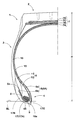
図3に示されるように、ビードコアbの回りで折返されるカーカスプライc1からなるカーカスc、及び、折り返されたカーカスプライc1の間に配されるビードエーペックスゴムdを具えた空気入りタイヤaが知られている。カーカスcは、トレッド部(図示省略)からサイドウォール部eをへてビード部fのビードコアbに至る本体部caと、ビードコアbの回りをタイヤ軸方向内側から外側に折り返される折返し部cbとを含んでいる。ビードエーペックスゴムdは、第1ゴム部daと、第1ゴム部daよりもタイヤ軸方向外側に配されかつ第1ゴム部daよりもゴム硬度が小さい第2ゴム部dbとを含んでいる。このような空気入りタイヤaにおいて、例えば、下記特許文献1には、第1ゴム部daのビードベースラインBLからのタイヤ半径方向の高さh1をビードエーペックスゴムdのビードベースラインBLからのタイヤ半径方向の高さhの40%〜60%に規定することにより、乗り心地性能と操縦安定性能とを両立させることが記載されている。 As shown in FIG. 3, a carcass c composed of a carcass ply c1 folded around the bead core b and a pneumatic tire a provided with a bead apex rubber d arranged between the folded carcass ply c1. Are known. The carcass c includes a main body portion ca that extends from the tread portion (not shown) through the sidewall portion e to the bead core b of the bead portion f, and a folded portion cb that is folded back from the inside to the outside in the tire axial direction around the bead core b. Includes. The bead apex rubber d includes a first rubber portion da and a second rubber portion db that is arranged outside the tire axial direction of the first rubber portion da and has a rubber hardness smaller than that of the first rubber portion da. In such a pneumatic tire a, for example, in Patent Document 1 below, the height h1 in the radial direction of the tire from the bead baseline BL of the first rubber portion da is the tire from the bead baseline BL of the bead apex rubber d. It is described that the ride comfort performance and the steering stability performance are compatible with each other by specifying 40% to 60% of the height h in the radial direction.
しかしながら、従来の空気入りタイヤaは、カーカスプライc1の折返し部cbのタイヤ半径方向の外端に作用する圧縮応力や前記外端の動きについて考慮されたものではなかった。例えば、走行時、ビード部に繰り返しの曲げ変形が作用すると、折返し部cbの外端に歪みによる動きが生じる。これにより、図3に仮想線で示されるように、ビード部fの外面がタイヤ軸方向内側に凹む凹部gが形成される他、耐久性能が悪化するという問題があった。また、第2ゴム部dbのゴム硬度を高めることで、前記繰り返しの曲げ変形による前記外端の歪みを抑制することができるが、折返し部cbの前記外端に作用する圧縮応力が緩和されず、耐久性能が悪化するという問題もあった。 However, in the conventional pneumatic tire a, the compressive stress acting on the outer end of the folded-back portion cb of the carcass ply c1 in the radial direction of the tire and the movement of the outer end are not taken into consideration. For example, when the bead portion is repeatedly bent and deformed during traveling, the outer end of the folded portion cb is distorted. As a result, as shown by a virtual line in FIG. 3, there is a problem that the outer surface of the bead portion f is recessed inward in the tire axial direction, and the durability performance is deteriorated. Further, by increasing the rubber hardness of the second rubber portion db, the distortion of the outer end due to the repeated bending deformation can be suppressed, but the compressive stress acting on the outer end of the folded portion cb is not relaxed. There was also a problem that the durability performance deteriorated.
本発明は、以上のような問題点に鑑み案出なされたもので、ゴム硬度が大きいビードエーペックスゴムの第1ゴムのタイヤ半径方向の高さと、カーカスプライの折返し部のタイヤ半径方向の高さとを改善することを基本として、耐久性能を高めた空気入りタイヤを提供することを主たる目的としている。 The present invention has been devised in view of the above problems, and includes the height of the first rubber of the bead apex rubber having a large rubber hardness in the tire radial direction and the height of the folded portion of the carcass ply in the tire radial direction. The main purpose is to provide pneumatic tires with improved durability on the basis of improvement.
本発明は、トレッド部からサイドウォール部をへてビード部のビードコアに至る本体部と、前記ビードコアの回りをタイヤ軸方向内側から外側に折り返される折返し部とを含むカーカスプライからなるカーカス、及び、前記本体部と前記折返し部との間を前記ビードコアからタイヤ半径方向外側にのびるビードエーペックスゴムを含む空気入りタイヤであって、前記ビードエーペックスゴムは、第1ゴム部と、前記第1ゴム部よりもタイヤ軸方向外側に配されかつ前記第1ゴム部よりもゴム硬度が小さい第2ゴム部とを有し、正規リムにリム組みされかつ正規内圧が充填された無負荷の正規状態において、前記第1ゴム部のタイヤ半径方向の外端のビードベースラインからの高さH1と、前記折返し部のタイヤ半径方向の外端のビードベースラインからの高さH2との比H1/H2は、1.4〜1.7であることを特徴とする。 The present invention comprises a carcass including a main body portion extending from a tread portion through a sidewall portion to a bead core of a bead portion, and a folded portion that folds around the bead core from the inside to the outside in the tire axial direction, and a carcass composed of a carcass ply. A pneumatic tire containing bead apex rubber extending outward from the bead core in the radial direction of the tire between the main body portion and the folded portion, and the bead apex rubber is formed from a first rubber portion and the first rubber portion. Also has a second rubber portion that is arranged on the outer side in the tire axial direction and has a rubber hardness smaller than that of the first rubber portion, and is assembled on a regular rim and is filled with a regular internal pressure in a normal state of no load. The ratio H1 / H2 of the height H1 from the bead baseline at the outer end in the tire radial direction of the first rubber portion to the height H2 from the bead baseline at the outer end in the tire radial direction of the folded portion is 1. It is characterized by being .4 to 1.7.
本発明に係る空気入りタイヤは、前記カーカスプライに沿って前記ビードコアの回りを断面略U字状にのびるビード補強層を有し、前記ビード補強層は、前記本体部のタイヤ軸方向内側をのびる内側部分と、前記折返し部のタイヤ軸方向外側をのびる外側部分とを含み、前記折返し部のタイヤ半径方向の外端位置での前記第1ゴム部のタイヤ軸方向厚さTaと前記ビードエーペックスゴムのタイヤ軸方向の厚さT1との比Ta/T1は、前記外側部分のタイヤ半径方向の外端位置での前記第1ゴム部のタイヤ軸方向厚さTbと前記ビードエーペックスゴムのタイヤ軸方向の厚さT2との比Tb/T2よりも小さいのが望ましい。 The pneumatic tire according to the present invention has a bead reinforcing layer extending around the bead core in a substantially U-shaped cross section along the carcass ply, and the bead reinforcing layer extends inside the main body portion in the tire axial direction. The tire axial thickness Ta of the first rubber portion and the bead apex rubber at the outer end position of the folded portion in the tire radial direction, including the inner portion and the outer portion extending outside in the tire axial direction of the folded portion. Ta / T1 with respect to the thickness T1 in the tire axial direction is the tire axial thickness Tb of the first rubber portion at the outer end position in the tire radial direction of the outer portion and the tire axial direction of the bead apex rubber. It is desirable that the thickness is smaller than the ratio Tb / T2 to T2.
本発明に係る空気入りタイヤは、前記比Ta/T1は、0.45〜0.55であり、前記比Tb/T2が、0.70〜0.80であるのが望ましい。 In the pneumatic tire according to the present invention, the ratio Ta / T1 is preferably 0.45 to 0.55, and the ratio Tb / T2 is preferably 0.70 to 0.80.
本発明に係る空気入りタイヤは、前記比Ta/T1と前記比Tb/T2との比(Ta/T1)/(Tb/T2)が、0.60〜0.70であるのが望ましい。 In the pneumatic tire according to the present invention, it is desirable that the ratio (Ta / T1) / (Tb / T2) of the ratio Ta / T1 to the ratio Tb / T2 is 0.60 to 0.70.
本発明の空気入りタイヤは、トレッド部からサイドウォール部をへてビード部のビードコアに至る本体部と、ビードコアの回りをタイヤ軸方向内側から外側に折り返される折返し部とを含むカーカスプライからなるカーカス、及び、本体部と折返し部との間をビードコアからタイヤ半径方向外側にのびるビードエーペックスゴムを含んでいる。ビードエーペックスゴムは、第1ゴム部と、第1ゴム部よりもタイヤ軸方向外側に配されかつ第1ゴム部よりもゴム硬度が小さい第2ゴム部とを有している。このようなビードエーペックスゴムは、ビード部の変形に際して、十分な曲げ剛性を確保しつつカーカスプライの折返し部に作用する圧縮応力を緩和して、ビード部の耐久性能を効果的に高めている。 The pneumatic tire of the present invention is a carcass composed of a carcass ply including a main body portion extending from a tread portion through a sidewall portion to a bead core of a bead portion and a folded portion that is folded back from the inside to the outside in the tire axial direction around the bead core. And, the bead apex rubber extending from the bead core to the outside in the radial direction of the tire is included between the main body portion and the folded portion. The bead apex rubber has a first rubber portion and a second rubber portion that is arranged outside the tire axial direction from the first rubber portion and has a rubber hardness smaller than that of the first rubber portion. Such bead apex rubber effectively enhances the durability performance of the bead portion by relaxing the compressive stress acting on the folded portion of the carcass ply while ensuring sufficient bending rigidity when the bead portion is deformed.
正規状態において、第1ゴム部のタイヤ半径方向の外端のビードベースラインからの高さH1と、折返し部のタイヤ半径方向の外端のビードベースラインからの高さH2との比H1/H2は、1.4〜1.7である。これにより、折返し部の外端のタイヤ半径方向位置において、第1ゴム部と、ゴム硬度の小さい第2ゴム部とが最適に配分されるので、折返し部の外端の歪みが小さくなり、かつ、この外端に作用する圧縮応力が緩和される。従って、ビード部の折返し部の外端位置での凹みや損傷が抑制されるため、耐久性能が向上する。 In the normal state, the ratio H1 / H2 of the height H1 from the bead baseline at the outer end in the tire radial direction of the first rubber portion and the height H2 from the bead baseline at the outer end in the tire radial direction of the folded portion. Is 1.4 to 1.7. As a result, the first rubber portion and the second rubber portion having a low rubber hardness are optimally distributed at the position of the outer end of the folded portion in the tire radial direction, so that the distortion of the outer end of the folded portion is reduced and the distortion of the outer end is reduced. , The compressive stress acting on this outer end is relaxed. Therefore, dents and damages at the outer end position of the folded portion of the bead portion are suppressed, so that the durability performance is improved.
以下、本発明の実施の一形態が図面に基づき説明される。
図1は、本発明の一実施形態を示す空気入りタイヤ(以下、単に「タイヤ」ということがある)1の正規状態のタイヤ子午線断面図である。本発明は、乗用車用のタイヤにも採用されるが、とりわけ、トラックやバス等の重荷重用のタイヤに好適に採用される。
Hereinafter, embodiments of the present invention will be described with reference to the drawings.
FIG. 1 is a cross-sectional view of a tire meridian in a normal state of a pneumatic tire (hereinafter, may be simply referred to as a “tire”) 1 showing an embodiment of the present invention. The present invention is also adopted for tires for passenger cars, but is particularly preferably adopted for tires for heavy loads such as trucks and buses.
本明細書において、「正規状態」とは、タイヤが、正規リム(図示せず)にリム組みされかつ正規内圧が充填されしかも無負荷である状態とし、特に断りがない場合、タイヤ各部の寸法等は、この正規状態で測定された値とする。 In the present specification, the "normal state" means that the tire is rim-assembled on a normal rim (not shown), is filled with normal internal pressure, and has no load, and unless otherwise specified, the dimensions of each part of the tire. Etc. are the values measured in this normal state.
「正規リム」とは、タイヤが基づいている規格を含む規格体系において、各規格がタイヤ毎に定めているリムであり、JATMAであれば"標準リム"、TRAであれば "Design Rim" 、ETRTOであれば "Measuring Rim"となる。また、「正規内圧」とは、タイヤが基づいている規格を含む規格体系において、各規格がタイヤ毎に定めている空気圧であり、JATMAであれば"最高空気圧"、TRAであれば表 "TIRE LOAD LIMITS AT VARIOUS COLD INFLATION PRESSURES" に記載の最大値、ETRTOであれば "INFLATION PRESSURE" とする。 A "regular rim" is a rim defined for each tire in the standard system including the standard on which the tire is based. For JATMA, "standard rim", for TRA, "Design Rim", If it is ETRTO, it will be "Measuring Rim". In addition, "regular internal pressure" is the air pressure defined for each tire in the standard system including the standard on which the tire is based. For JATMA, it is the "maximum air pressure", and for TRA, it is the table "TIRE". The maximum value described in "LOAD LIMITS AT VARIOUS COLD INFLATION PRESSURES", or "INFLATION PRESSURE" for ETRTO.
本実施形態のタイヤ1は、カーカス6とベルト層7とビードエーペックスゴム8とビード補強層9とを含んでいる。
The tire 1 of the present embodiment includes a
カーカス6は、トレッド部2からサイドウォール部3をへてビード部4のビードコア5までのびている。カーカス6は、少なくとも1枚、本実施形態では、1枚のカーカスプライ6Aからなる。カーカスプライ6Aは、一対のビードコア5、5間をトロイド状に跨る本体部6aと、この本体部6aの両側に連なりかつビードコア5の回りをタイヤ軸方向内側から外側に折り返された折返し部6bとを含んでいる。カーカスプライ6Aは、タイヤ赤道Cに対して例えば75〜90°の角度で傾けられたカーカスコードを含んでいる。カーカスコードには、例えば有機繊維コード又はスチールコードが採用される。
The
本実施形態の折返し部6bは、そのタイヤ半径方向の外端6eが、ビード部4、より具体的には、ビードエーペックスゴム8とタイヤ半径方向において重複している。
In the folded-
ベルト層7は、カーカス6のタイヤ半径方向外側かつトレッド部2の内部に配されている。ベルト層7は、少なくとも2枚、本実施形態では、タイヤ半径方向の内外に4枚のベルトプライ7A乃至7Dから構成されている。タイヤ半径方向の最も内側に配されたベルトプライ7Aは、例えば、タイヤ赤道Cに対して45〜75°の角度で傾けられている。ベルトプライ7Aよりもタイヤ半径方向外側に配された各ベルトプライ7B乃至7Dは、例えば、タイヤ赤道Cに対して10〜35°の角度で傾けられている。各ベルトプライ7A乃至7Dは、例えば、ベルトコードが互いに交差する向きに重ねられている。ベルトプライ7A乃至7Dのベルトコードは、スチールコード等の高弾性のものが望ましい。
The
ビードコア5は、例えばスチール製のビードワイヤを巻回してなるリング状をなし、本実施形態では、断面横長の偏平六角形状のものが採用される。ビードコア5は、そのタイヤ半径方向内面がビード底面4Sに沿ってのびることにより、リムとの嵌合力を広範囲に亘って高めている。
The
図2に示されるように、ビードエーペックスゴム8は、第1ゴム部10と、第1ゴム部10よりもタイヤ軸方向外側に配されかつ第1ゴム部10よりもゴム硬度が小さい第2ゴム部11とを有している。このようなビードエーペックスゴム8は、ビード部4の変形に際して、十分な曲げ剛性を確保しつつカーカスプライ6Aの折返し部6bに作用する圧縮応力を緩和して、ビード部4の耐久性能を効果的に高めている。
As shown in FIG. 2, the
一般に、カーカス6の本体部6aにかかる引張力は、折返し部6bにかかる引張力よりも大きい。本実施形態では、このような本体部6aが配されるタイヤ軸方向の内側に、ゴム硬度が高い第1ゴム部10が大きく設けられているので、ビード部4の撓みが効果的に低減され、耐久性能を高めることが可能となる。
Generally, the tensile force applied to the
第1ゴム部10のタイヤ半径方向の外端10eのビードベースラインBLからの高さH1と、折返し部6bのタイヤ半径方向の外端6eのビードベースラインBLからの高さH2との比H1/H2は、1.4〜1.7である。前記比H1/H2が1.4未満の場合、折返し部6bの外端6eのタイヤ半径方向位置において、第1ゴム部10に比してゴム硬度の小さい第2ゴム部11の比率が過度に高くなる。このため、折返し部6bの外端6eに歪みによる大きな動きが生じるので、耐久性能が悪化する。また、比H1/H2が1.7を超える場合、折返し部6bの外端6eのタイヤ半径方向位置において、第1ゴム部10に比してゴム硬度の小さい第2ゴム部11の比率が過度に小さくなる。このため、折返し部6bの外端6eに作用する圧縮応力を緩和できず、損傷が生じるので、耐久性能が悪化する。本発明のタイヤ1は、比H1/H2が1.4〜1.7に規定されるので、第1ゴム部10と、第2ゴム部11とが最適に配分されて、折返し部6bの外端6eの歪みが小さくなり、かつ、この外端6eに作用する圧縮応力が緩和されるため、耐久性能が向上する。
The ratio H1 of the height H1 of the
第1ゴム部10のゴム硬度Haは、例えば、80〜95度が望ましい。第2ゴム部11のゴム硬度Hbは、例えば、50〜70度が望ましい。第1ゴム部10のゴム硬度Haが80度未満の場合、必要なビード剛性が維持されず、耐久性能が悪化するおそれがある。第1ゴム部10のゴム硬度Haが95度を超える場合、ビード剛性が過度に高くなり、折返し部6bの外端6eに作用する圧縮応力を緩和できず、損傷が生じるおそれがある。また、第2ゴム部11のゴム硬度Hbが50度未満の場合、ビード剛性が低下するおそれがある。第2ゴム部11のゴム硬度Hbが70度を超える場合、折返し部6bの外端6eに作用する圧縮応力が緩和されないおそれがある。
The rubber hardness Ha of the
上述の作用をより効果的に発揮させるため、第1ゴム部10と第2ゴム部11とのゴム硬度の差(Ha−Hb)は、10〜40度が望ましい。本明細書において、「ゴム硬度」は、JIS−K6253に準拠し、23℃の環境下におけるデュロメータータイプAによるゴム硬さである。
In order to exert the above-mentioned action more effectively, the difference in rubber hardness (Ha—Hb) between the
ビードエーペックスゴム8のタイヤ半径方向の外端8eのビードベースラインBLからの高さH3は、第1ゴム部10の外端10eの前記高さH1の1.2〜1.6倍であるのが望ましい。これにより、ビード剛性が高く維持されつつ、折返し部6bの外端6eに作用する圧縮応力が効果的に緩和されるので、ビード部4の耐久性能が高められる。
The height H3 of the
上述の作用をより効果的に発揮させるために、第1ゴム部10の外端10eの高さH1は、タイヤ断面高さH(図1に示す)の15%〜30%が望ましい。
In order to exert the above-mentioned action more effectively, the height H1 of the
第2ゴム部11のタイヤ半径方向の内端11iのビードベースラインBLからの高さH4は、例えば、第1ゴム部10の外端10eの高さH1の20%〜35%が望ましい。これにより、折返し部6bの外端6eに作用する圧縮応力が効果的に緩和される。
The height H4 of the
ビード補強層9は、カーカスプライ6Aに沿ってビードコア5の回りを断面略U字状にのびている。ビード補強層9は、本実施形態では、本体部6aのタイヤ軸方向内側をのびる内側部分12、折返し部6bのタイヤ軸方向外側をのびる外側部分13、及び、内側部分12と外側部分13とを継ぎかつビードコア5の半径方向内側を通る底片部分14を含んでいる。
The
ビード補強層9は、本実施形態では、スチール製の補強コードをタイヤ赤道Cに対して、例えば、15〜60度の角度で配したコードプライからなる。ビード補強層9は、ビード部4を強固に補強する。
In the present embodiment, the
内側部分12のタイヤ半径方向の外端12e近傍では、走行時、大きな引張応力が作用する箇所であり、本体部6aや第1ゴム部10で保護されている。また、外側部分13のタイヤ半径方向の外端13eでは、カーカスプライ抜けによるタイヤ半径方向内側への力が作用しやすい。このため、内側部分12の外端12eを外側部分13の外端13eよりもタイヤ半径方向内側に位置させて、タイヤ質量を小さく維持しつつ、耐久性能を高めている。
In the vicinity of the
内側部分12の前記外端12eのビードベースラインBLからの高さH6が、外側部分13の前記外端13eのビードベースラインBLからの高さH5よりも過度に小さい場合、内側部分12に大きな曲げ戻り力が作用して、内側部分12が本体部6aから剥離する。これにより、ビード剛性が低下するおそれがある。このような観点より、内側部分12の前記外端12eの高さH6は、外側部分13の前記外端13eの高さH5の60%〜90%であるのが望ましい。
When the height H6 of the
外側部分13の外端13eの前記高さH5は、折返し部6bの前記外端6eの前記高さH2よりも小さいのが望ましい。これにより、走行によるタイヤ変形時でも、外側部分13の前記外端13eに作用する圧縮応力が小さく維持されるので、損傷が抑制される。折返し部6bの外端6eの高さH5が過度に小さい場合、ビード部剛性が低下する。このような観点より、外側部分13の前記外端13eのビードベースラインBLからの高さH5は、折返し部6bの前記外端6eの前記高さH2の60%〜90%であるのが望ましい。
It is desirable that the height H5 of the
折返し部6bのタイヤ半径方向の外端6e位置での第1ゴム部10のタイヤ軸方向厚さTaとビードエーペックスゴム8のタイヤ軸方向の厚さT1との比を、折返し部6bのゴム厚さの比Ta/T1とする。外側部分13のタイヤ半径方向の外端13e位置での第1ゴム部10のタイヤ軸方向厚さTbとビードエーペックスゴム8のタイヤ軸方向の厚さT2との比を、外側部分13のゴム厚さの比Tb/T2とする。本実施形態のタイヤ1では、折返し部6bのゴム厚さの比Ta/T1は、外側部分13のゴム厚さの比Tb/T2よりも小とするのが望ましい。これにより、第1ゴム部10と第2ゴム部11とのゴム容積が、さらに、効果的に配されることになる。従って、折返し部6bの外端6eや外側部分13の外端13eの動きが小さくなり、ビード部4の歪みの発生を抑制することができ、かつ、折返し部6bの外端6eに作用する圧縮応力を緩和することができる。このように、本実施形態では、両外端13e、及び、外端6eでのタイヤ半径方向における第1ゴム部10の厚さの比に規定して、両外端13e、6eの歪みを抑制しつつ、両外端13e、6eに作用する圧縮応力を緩和して、バランス良く耐久性能を向上する。
The ratio of the tire axial thickness Ta of the
折返し部6bのゴム厚さの比Ta/T1は、0.45〜0.55であるのが望ましい。外側部分13のゴム厚さの比Tb/T2は、0.70〜0.80であるのが望ましい。折返し部6bのゴム厚さの比Ta/T1が0.45未満の場合、折返し部6bの外端6eの歪みによる動きを抑制できないおそれがある。折返し部6bのゴム厚さの比Ta/T1が0.55を超える場合、折返し部6bの外端6eに作用する圧縮応力を緩和できないおそれがある。外側部分13のゴム厚さの比Tb/T2が0.70未満の場合、折返し部6bの外端6eや外側部分13の外端13eの歪みを抑制できないおそれがある。外側部分13のゴム厚さの比Tb/T2が0.80を超える場合、折返し部6bの外端6eや外側部分13の外端13eに作用する圧縮応力を緩和できないおそれがある。
The rubber thickness ratio Ta / T1 of the folded-
上述の作用をより一層、効果的に発揮させるため、前記比Ta/T1と前記比Tb/T2との比(Ta/T1)/(Tb/T2)は、0.60〜0.70が望ましい。 In order to exert the above-mentioned action more effectively, the ratio (Ta / T1) / (Tb / T2) of the ratio Ta / T1 to the ratio Tb / T2 is preferably 0.60 to 0.70. ..
また、図1に示されるように、本実施形態のタイヤ1は、インナーライナー層15とインスレーションゴム16とチェーファゴム17とを含んでいる。
Further, as shown in FIG. 1, the tire 1 of the present embodiment includes an
インナーライナー層15は、カーカス6に沿ってビード部4、4間を連続してのびる。インナーライナー層15は、例えば、ブチル系ゴムなどの空気不透過性ゴムからなる。インナーライナー層15は、本実施形態では、タイヤ半径方向側がビードベースラインBLよりもタイヤ半径方向内側で終端している。これにより、タイヤ内腔内の空気の圧力が高く維持される。
The
インスレーションゴム16は、インナーライナー層15とカーカス6との間に配されている。インスレーションゴム16は、インナーライナー層15とカーカス6との接着力を高めて層間剥離を防ぐ。
The
インスレーションゴム16は、インナーライナー層15の全長に亘ってインナーライナー層15に接して半径方向内外に延在している。インスレーションゴム16のタイヤ半径方向内端16eは、ビード補強層9の外側部分13よりもタイヤ軸方向内側で終端している。
The
チェーファゴム17は、ビード補強層9のタイヤ半径方向内側に位置している。チェーファゴム17は、ベース部17Aと外の立上げ部17Bと内の立上げ部17Cとを有している。ベース部17Aは、ビード底面4Sで露出している。外の立上げ部17Bは、ベース部17Aに連なりタイヤ軸方向外側をタイヤ半径方向外側にのびている。内の立上げ部17Cは、ベース部17Aに連なりタイヤ軸方向外側をタイヤ半径方向外側に先細状にのびている。
The
以上、本発明のタイヤについて詳細に説明したが、本発明は上記の具体的な実施形態に限定されることなく種々の態様に変更して実施しうるのは言うまでもない。 Although the tire of the present invention has been described in detail above, it goes without saying that the present invention can be implemented by changing to various aspects without being limited to the above-mentioned specific embodiment.
図1の基本構造を有する重荷重用タイヤ(サイズ11.00R20)を、表1の仕様に基づき試作するとともに、各試供タイヤの耐久性能がテストされた。なお、共通仕様は以下の通りである。
・ビードエーペックスゴム
第1ゴム部
ゴム硬度:87度
外端のタイヤ半径方向高さ/タイヤ断面高さ(H1/H):27%
第2ゴム部
ゴム硬度:60度
外端のタイヤ半径方向高さ(H3/H1):1.4倍
内端のタイヤ半径方向高さ(H4/H1):27%
・ビード補強層
外側部分の外端のタイヤ半径方向高さ(H5/H2):75%
内側部分の外端のタイヤ半径方向高さ(H6/H5):75%
テスト方法は、次の通りである。
A heavy-duty tire (size 11.00R20) having the basic structure shown in FIG. 1 was prototyped based on the specifications shown in Table 1, and the durability performance of each sample tire was tested. The common specifications are as follows.
・ Bead Apex rubber 1st rubber part Rubber hardness: 87 degrees Outer end tire radial height / tire cross-sectional height (H1 / H): 27%
2nd rubber part Rubber hardness: 60 degrees Outer end tire radial height (H3 / H1): 1.4 times Inner end tire radial height (H4 / H1): 27%
-Bead reinforcement layer Height in the radial direction of the tire at the outer end of the outer part (H5 / H2): 75%
Tire radial height at the outer end of the inner part (H6 / H5): 75%
The test method is as follows.
<耐久性能(ビード損傷)>
各試供タイヤをリム組みして、下記の条件下にてドラム試験機上を走行させ、ビードの損傷が発生するまでの走行時間が測定された。結果は、比較例1を100とする指数で表示されている。数値が大きい程、良好である。
リム:8.5×20
内圧:800kPa(全輪)
縦荷重:94kN
速度:20km/h
<Durability (bead damage)>
Each test tire was assembled on the rim and run on the drum tester under the following conditions, and the running time until the bead was damaged was measured. The results are displayed as an exponent with Comparative Example 1 as 100. The larger the number, the better.
Rim: 8.5 x 20
Internal pressure: 800kPa (all wheels)
Vertical load: 94kN
Speed: 20km / h
<耐久性能(ビード部変形量)>
リム組みされた各試供タイヤを用いて、下記の条件下にてドラム試験機上を走行させ、走行前後におけるタイヤ表面の3点でのタイヤ軸方向への変形量が測定された。走行前は、正規内圧の5%の内圧が充填された5%内圧状態で測定された。走行後は、正規内圧が充填されしかも無負荷である正規内圧状態で測定された。
リム:8.5×20
内圧:800kPa(全輪)
縦荷重:37.6kN
速度:80km/h
走行距離:50000km
測定位置1:ビードエーペックスゴムの第1ゴム部の外端のタイヤ半径方向の高さ位置
測定位置2:カーカスの折返し部の外端のタイヤ半径方向の高さ位置
測定位置3:ビード補強層の外側部分の外端のタイヤ半径方向の高さ位置
測定位置1での走行前後の変形量をa、測定位置2での走行前後の変形量をb、及び、測定位置3での走行前後の変形量をcとした場合、
a=b=cを1、
a=b≠cを2、
a≠b≠cを3
と表示し、1及び2を合格、3を不合格とする。なお、a、b、cの変形量の差が1mm未満のものは、同じ変形量とする。
テストの結果が表1に示される。
<Durability (deformation amount of bead part)>
Each test tire assembled with a rim was run on a drum tester under the following conditions, and the amount of deformation in the tire axial direction at three points on the tire surface before and after running was measured. Before running, the measurement was performed in a 5% internal pressure state filled with an internal pressure of 5% of the normal internal pressure. After running, the measurement was performed in a normal internal pressure state in which the normal internal pressure was charged and there was no load.
Rim: 8.5 x 20
Internal pressure: 800kPa (all wheels)
Vertical load: 37.6kN
Speed: 80km / h
Mileage: 50,000km
Measurement position 1: Height position in the tire radial direction at the outer end of the first rubber part of the bead apex rubber Measurement position 2: Height position in the tire radial direction at the outer end of the folded part of the carcass Measurement position 3: Of the bead reinforcement layer Height position of the outer end in the tire radial direction The amount of deformation before and after running at the measurement position 1 is a, the amount of deformation before and after running at the
a = b = c is 1,
a = b ≠ c is 2,
a ≠ b ≠
Is displayed, 1 and 2 are passed, and 3 is rejected. If the difference between the deformation amounts of a, b, and c is less than 1 mm, the same deformation amount is used.
The test results are shown in Table 1.

テストの結果、実施例のタイヤは、比較例のタイヤに比べて、各性能が効果的に向上していることが確認できる。また、上記と異なるタイヤサイズや、第1ゴム部のゴム硬度を80〜95度、第2ゴム部のゴム硬度を50〜70度の範囲で変化させた例についてもテストを行ったが、同じ傾向が示された。 As a result of the test, it can be confirmed that each performance of the tire of the example is effectively improved as compared with the tire of the comparative example. In addition, tests were also conducted on tire sizes different from the above, and examples in which the rubber hardness of the first rubber part was changed in the range of 80 to 95 degrees and the rubber hardness of the second rubber part was changed in the range of 50 to 70 degrees. A tendency was shown.
1 空気入りタイヤ
6 カーカス
6a 本体部
6b 折返し部
6e 折返し部の外端
6A カーカスプライ
10 第1ゴム部
10e 第1ゴム部の外端
11 第2ゴム部
BL ビードベースライン
1
Claims (2)
前記本体部と前記折返し部との間を前記ビードコアからタイヤ半径方向外側にのびるビードエーペックスゴムを含む空気入りタイヤであって、
前記ビードエーペックスゴムは、第1ゴム部と、前記第1ゴム部よりもタイヤ軸方向外側に配されかつ前記第1ゴム部よりもゴム硬度が小さい第2ゴム部とを有し、
正規リムにリム組みされかつ正規内圧が充填された無負荷の正規状態において、
前記第1ゴム部のタイヤ半径方向の外端のビードベースラインからの高さH1と、前記折返し部のタイヤ半径方向の外端のビードベースラインからの高さH2との比H1/H2は、1.4〜1.7であり、
前記カーカスプライに沿って前記ビードコアの回りを断面略U字状にのびるビード補強層を有し、
前記ビード補強層は、前記本体部のタイヤ軸方向内側をのびる内側部分と、前記折返し部のタイヤ軸方向外側をのびる外側部分とを含み、
前記折返し部のタイヤ半径方向の外端位置での前記第1ゴム部のタイヤ軸方向厚さTaと前記ビードエーペックスゴムのタイヤ軸方向の厚さT1との比Ta/T1は、
前記外側部分のタイヤ半径方向の外端位置での前記第1ゴム部のタイヤ軸方向厚さTbと前記ビードエーペックスゴムのタイヤ軸方向の厚さT2との比Tb/T2よりも小さく、
前記比Ta/T1は、0.45〜0.55であり、
前記比Tb/T2は、0.70〜0.80であることを特徴とする空気入りタイヤ。 A carcass composed of a carcass ply including a main body portion extending from the tread portion through the sidewall portion to the bead core of the bead portion and a folded portion that is folded back from the inside to the outside in the tire axial direction around the bead core, and
A pneumatic tire containing bead apex rubber extending outward in the radial direction of the tire from the bead core between the main body portion and the folded portion.
The bead apex rubber has a first rubber portion and a second rubber portion arranged outside the first rubber portion in the tire axial direction and having a rubber hardness smaller than that of the first rubber portion.
In the normal state of no load, which is assembled to the regular rim and filled with the regular internal pressure,
The ratio H1 / H2 of the height H1 from the bead baseline at the outer end in the tire radial direction of the first rubber portion to the height H2 from the bead baseline at the outer end in the tire radial direction of the folded portion is 1.4 to 1.7 der is,
It has a bead reinforcing layer extending around the bead core in a substantially U-shaped cross section along the carcass ply.
The bead reinforcing layer includes an inner portion extending inside the tire axial direction of the main body portion and an outer portion extending outside the tire axial direction of the folded portion.
The ratio Ta / T1 of the tire axial thickness Ta of the first rubber portion to the tire axial thickness T1 of the bead apex rubber at the outer end position of the folded portion in the tire radial direction is
The ratio of the tire axial thickness Tb of the first rubber portion to the tire axial thickness T2 of the bead apex rubber at the outer end position in the tire radial direction of the outer portion is smaller than Tb / T2.
The ratio Ta / T1 is 0.45 to 0.55.
The pneumatic tire having a ratio Tb / T2 of 0.70 to 0.80.
前記本体部と前記折返し部との間を前記ビードコアからタイヤ半径方向外側にのびるビードエーペックスゴムを含む空気入りタイヤであって、A pneumatic tire containing bead apex rubber extending outward in the radial direction of the tire from the bead core between the main body portion and the folded portion.
前記ビードエーペックスゴムは、第1ゴム部と、前記第1ゴム部よりもタイヤ軸方向外側に配されかつ前記第1ゴム部よりもゴム硬度が小さい第2ゴム部とを有し、The bead apex rubber has a first rubber portion and a second rubber portion arranged outside the first rubber portion in the tire axial direction and having a rubber hardness smaller than that of the first rubber portion.
正規リムにリム組みされかつ正規内圧が充填された無負荷の正規状態において、In the normal state of no load, which is assembled to the regular rim and filled with the regular internal pressure,
前記第1ゴム部のタイヤ半径方向の外端のビードベースラインからの高さH1と、前記折返し部のタイヤ半径方向の外端のビードベースラインからの高さH2との比H1/H2は、1.4〜1.7であり、The ratio H1 / H2 of the height H1 from the bead baseline at the outer end in the tire radial direction of the first rubber portion to the height H2 from the bead baseline at the outer end in the tire radial direction of the folded portion is It is 1.4 to 1.7,
前記カーカスプライに沿って前記ビードコアの回りを断面略U字状にのびるビード補強層を有し、It has a bead reinforcing layer extending around the bead core in a substantially U-shaped cross section along the carcass ply.
前記ビード補強層は、前記本体部のタイヤ軸方向内側をのびる内側部分と、前記折返し部のタイヤ軸方向外側をのびる外側部分とを含み、The bead reinforcing layer includes an inner portion extending inside the tire axial direction of the main body portion and an outer portion extending outside the tire axial direction of the folded portion.
前記折返し部のタイヤ半径方向の外端位置での前記第1ゴム部のタイヤ軸方向厚さTaと前記ビードエーペックスゴムのタイヤ軸方向の厚さT1との比Ta/T1は、The ratio Ta / T1 of the tire axial thickness Ta of the first rubber portion to the tire axial thickness T1 of the bead apex rubber at the outer end position of the folded portion in the tire radial direction is
前記外側部分のタイヤ半径方向の外端位置での前記第1ゴム部のタイヤ軸方向厚さTbと前記ビードエーペックスゴムのタイヤ軸方向の厚さT2との比Tb/T2よりも小さく、The ratio of the tire axial thickness Tb of the first rubber portion to the tire axial thickness T2 of the bead apex rubber at the outer end position in the tire radial direction of the outer portion is smaller than Tb / T2.
前記比Ta/T1と前記比Tb/T2との比(Ta/T1)/(Tb/T2)は、0.60〜0.70であることを特徴とする空気入りタイヤ。A pneumatic tire characterized in that the ratio (Ta / T1) / (Tb / T2) of the ratio Ta / T1 to the ratio Tb / T2 is 0.60 to 0.70.
Priority Applications (4)
| Application Number | Priority Date | Filing Date | Title |
|---|---|---|---|
| JP2016216504A JP6848356B2 (en) | 2016-11-04 | 2016-11-04 | Pneumatic tires |
| US15/787,854 US11142027B2 (en) | 2016-11-04 | 2017-10-19 | Pneumatic tire |
| CN201710991575.8A CN108016215B (en) | 2016-11-04 | 2017-10-23 | Pneumatic tire |
| EP17198725.8A EP3318424B1 (en) | 2016-11-04 | 2017-10-27 | Pneumatic tire |
Applications Claiming Priority (1)
| Application Number | Priority Date | Filing Date | Title |
|---|---|---|---|
| JP2016216504A JP6848356B2 (en) | 2016-11-04 | 2016-11-04 | Pneumatic tires |
Publications (2)
| Publication Number | Publication Date |
|---|---|
| JP2018070110A JP2018070110A (en) | 2018-05-10 |
| JP6848356B2 true JP6848356B2 (en) | 2021-03-24 |
Family
ID=60190680
Family Applications (1)
| Application Number | Title | Priority Date | Filing Date |
|---|---|---|---|
| JP2016216504A Active JP6848356B2 (en) | 2016-11-04 | 2016-11-04 | Pneumatic tires |
Country Status (4)
| Country | Link |
|---|---|
| US (1) | US11142027B2 (en) |
| EP (1) | EP3318424B1 (en) |
| JP (1) | JP6848356B2 (en) |
| CN (1) | CN108016215B (en) |
Families Citing this family (8)
| Publication number | Priority date | Publication date | Assignee | Title |
|---|---|---|---|---|
| JP7192470B2 (en) * | 2018-12-14 | 2022-12-20 | 住友ゴム工業株式会社 | pneumatic tire |
| JP7271961B2 (en) * | 2019-01-17 | 2023-05-12 | 横浜ゴム株式会社 | pneumatic tire |
| JP7272099B2 (en) * | 2019-05-10 | 2023-05-12 | 住友ゴム工業株式会社 | motorcycle tire |
| JP7494497B2 (en) * | 2020-03-11 | 2024-06-04 | 住友ゴム工業株式会社 | Pneumatic tires |
| JP7484287B2 (en) * | 2020-03-24 | 2024-05-16 | 住友ゴム工業株式会社 | Pneumatic tires |
| JP7484370B2 (en) * | 2020-04-17 | 2024-05-16 | 住友ゴム工業株式会社 | Pneumatic tires |
| CN111993846B (en) * | 2020-08-24 | 2022-05-31 | 安徽佳通乘用子午线轮胎有限公司 | Small-size all-steel tire with high bearing performance |
| EP4249286A1 (en) * | 2022-03-23 | 2023-09-27 | Sumitomo Rubber Industries, Ltd. | Heavy duty tire and production method for heavy duty tire |
Family Cites Families (23)
| Publication number | Priority date | Publication date | Assignee | Title |
|---|---|---|---|---|
| JPS61105202A (en) * | 1984-10-25 | 1986-05-23 | Toyo Tire & Rubber Co Ltd | Radial tire for large vehicle |
| JP2989750B2 (en) * | 1994-11-30 | 1999-12-13 | 住友ゴム工業株式会社 | Radial tire for high speed heavy load |
| JP3850049B2 (en) * | 1994-12-27 | 2006-11-29 | 株式会社ブリヂストン | Pneumatic tire |
| JP2002166710A (en) * | 2000-12-04 | 2002-06-11 | Sumitomo Rubber Ind Ltd | Pneumatic tire |
| JP4287706B2 (en) * | 2003-06-19 | 2009-07-01 | 住友ゴム工業株式会社 | Heavy duty tire |
| JP4363944B2 (en) * | 2003-10-03 | 2009-11-11 | 住友ゴム工業株式会社 | Heavy duty pneumatic tire |
| JP4685530B2 (en) * | 2005-07-08 | 2011-05-18 | 住友ゴム工業株式会社 | Pneumatic tire |
| US7461679B2 (en) * | 2005-11-08 | 2008-12-09 | Sumitomo Rubber Industries, Ltd. | Heavy duty tire |
| JP4950592B2 (en) | 2006-08-09 | 2012-06-13 | 住友ゴム工業株式会社 | Heavy duty tire |
| JP4976788B2 (en) * | 2006-09-04 | 2012-07-18 | 住友ゴム工業株式会社 | Heavy duty tire |
| JP2008062759A (en) * | 2006-09-06 | 2008-03-21 | Sumitomo Rubber Ind Ltd | Heavy load tire |
| JP4567763B2 (en) * | 2008-03-25 | 2010-10-20 | 住友ゴム工業株式会社 | Heavy duty tire |
| JP2010006322A (en) * | 2008-06-30 | 2010-01-14 | Yokohama Rubber Co Ltd:The | Pneumatic tire |
| JP4709911B2 (en) * | 2009-03-13 | 2011-06-29 | 住友ゴム工業株式会社 | Heavy duty tire |
| JP5379553B2 (en) * | 2009-04-28 | 2013-12-25 | 住友ゴム工業株式会社 | Heavy duty radial tire |
| DE102010016007A1 (en) * | 2010-03-18 | 2011-09-22 | Continental Reifen Deutschland Gmbh | Vehicle tires |
| JP2012121426A (en) * | 2010-12-08 | 2012-06-28 | Sumitomo Rubber Ind Ltd | Run flat tire |
| JP5457405B2 (en) * | 2011-07-29 | 2014-04-02 | 住友ゴム工業株式会社 | Pneumatic tire |
| JP5589015B2 (en) * | 2012-02-27 | 2014-09-10 | 住友ゴム工業株式会社 | Pneumatic tire |
| US20150298509A1 (en) * | 2012-03-14 | 2015-10-22 | Bridgestone Corporation | Tire |
| JP2014118069A (en) * | 2012-12-18 | 2014-06-30 | Sumitomo Rubber Ind Ltd | Pneumatic tire for heavy load |
| JP5993402B2 (en) * | 2014-05-23 | 2016-09-14 | 住友ゴム工業株式会社 | Heavy duty tube tire |
| DE102014211525A1 (en) * | 2014-06-17 | 2015-12-17 | Continental Reifen Deutschland Gmbh | Commercial vehicle tires |
-
2016
- 2016-11-04 JP JP2016216504A patent/JP6848356B2/en active Active
-
2017
- 2017-10-19 US US15/787,854 patent/US11142027B2/en active Active
- 2017-10-23 CN CN201710991575.8A patent/CN108016215B/en active Active
- 2017-10-27 EP EP17198725.8A patent/EP3318424B1/en active Active
Also Published As
| Publication number | Publication date |
|---|---|
| US11142027B2 (en) | 2021-10-12 |
| JP2018070110A (en) | 2018-05-10 |
| CN108016215B (en) | 2021-06-18 |
| CN108016215A (en) | 2018-05-11 |
| US20180126802A1 (en) | 2018-05-10 |
| EP3318424A1 (en) | 2018-05-09 |
| EP3318424B1 (en) | 2019-12-11 |
Similar Documents
| Publication | Publication Date | Title |
|---|---|---|
| JP6848356B2 (en) | Pneumatic tires | |
| JP5986513B2 (en) | Heavy duty tire | |
| US10589577B2 (en) | Heavy-duty pneumatic tire | |
| WO2013094300A1 (en) | Pneumatic tire for heavy loads | |
| JP6805530B2 (en) | Pneumatic tires | |
| EP3202595A1 (en) | Pneumatic tire | |
| JP2009057022A (en) | Pneumatic tire | |
| JP5497805B2 (en) | Heavy duty pneumatic tire | |
| JP2012218528A (en) | Tire for heavy load | |
| JP5932882B2 (en) | Pneumatic tire | |
| JP2015157579A (en) | pneumatic tire | |
| JP2010006322A (en) | Pneumatic tire | |
| JP6710995B2 (en) | Pneumatic tire | |
| JP7230479B2 (en) | Two-wheeled vehicle tire | |
| JP6610147B2 (en) | Pneumatic tire | |
| JP6315667B2 (en) | Pneumatic tire | |
| JP4812344B2 (en) | Pneumatic tire | |
| JP6790846B2 (en) | Pneumatic tires for heavy loads | |
| JP2021142857A (en) | Pneumatic tire | |
| JP6522995B2 (en) | Pneumatic tire | |
| JP2015221649A (en) | Tube type tire for heavy load | |
| JP5981228B2 (en) | Heavy duty pneumatic radial tire | |
| JP7188038B2 (en) | pneumatic tire | |
| JP6984247B2 (en) | Pneumatic tires | |
| JP6627519B2 (en) | Pneumatic tire |
Legal Events
| Date | Code | Title | Description |
|---|---|---|---|
| A621 | Written request for application examination |
Free format text: JAPANESE INTERMEDIATE CODE: A621 Effective date: 20190924 |
|
| A131 | Notification of reasons for refusal |
Free format text: JAPANESE INTERMEDIATE CODE: A131 Effective date: 20200728 |
|
| A977 | Report on retrieval |
Free format text: JAPANESE INTERMEDIATE CODE: A971007 Effective date: 20200722 |
|
| A521 | Request for written amendment filed |
Free format text: JAPANESE INTERMEDIATE CODE: A523 Effective date: 20200915 |
|
| TRDD | Decision of grant or rejection written | ||
| A01 | Written decision to grant a patent or to grant a registration (utility model) |
Free format text: JAPANESE INTERMEDIATE CODE: A01 Effective date: 20210202 |
|
| A61 | First payment of annual fees (during grant procedure) |
Free format text: JAPANESE INTERMEDIATE CODE: A61 Effective date: 20210215 |
|
| R150 | Certificate of patent or registration of utility model |
Ref document number: 6848356 Country of ref document: JP Free format text: JAPANESE INTERMEDIATE CODE: R150 |
|
| R250 | Receipt of annual fees |
Free format text: JAPANESE INTERMEDIATE CODE: R250 |