JP6845319B2 - How to attach the fabric to the panel for the suspended ceiling and the frame such as the suspended ceiling - Google Patents
How to attach the fabric to the panel for the suspended ceiling and the frame such as the suspended ceiling Download PDFInfo
- Publication number
- JP6845319B2 JP6845319B2 JP2019521197A JP2019521197A JP6845319B2 JP 6845319 B2 JP6845319 B2 JP 6845319B2 JP 2019521197 A JP2019521197 A JP 2019521197A JP 2019521197 A JP2019521197 A JP 2019521197A JP 6845319 B2 JP6845319 B2 JP 6845319B2
- Authority
- JP
- Japan
- Prior art keywords
- fabric
- frame
- fastening bracket
- attached
- edge
- Prior art date
- Legal status (The legal status is an assumption and is not a legal conclusion. Google has not performed a legal analysis and makes no representation as to the accuracy of the status listed.)
- Active
Links
- 239000004744 fabric Substances 0.000 title claims description 266
- 230000002093 peripheral effect Effects 0.000 claims description 55
- 238000000034 method Methods 0.000 claims description 33
- 239000000463 material Substances 0.000 claims description 6
- 230000008878 coupling Effects 0.000 description 7
- 238000010168 coupling process Methods 0.000 description 7
- 238000005859 coupling reaction Methods 0.000 description 7
- 239000011888 foil Substances 0.000 description 6
- 239000000428 dust Substances 0.000 description 4
- 230000037303 wrinkles Effects 0.000 description 4
- 230000007246 mechanism Effects 0.000 description 2
- 230000008439 repair process Effects 0.000 description 2
- 230000003252 repetitive effect Effects 0.000 description 2
- 229910000831 Steel Inorganic materials 0.000 description 1
- 238000004026 adhesive bonding Methods 0.000 description 1
- 229910052782 aluminium Inorganic materials 0.000 description 1
- XAGFODPZIPBFFR-UHFFFAOYSA-N aluminium Chemical compound [Al] XAGFODPZIPBFFR-UHFFFAOYSA-N 0.000 description 1
- 238000005452 bending Methods 0.000 description 1
- 230000005540 biological transmission Effects 0.000 description 1
- 238000006073 displacement reaction Methods 0.000 description 1
- 238000005516 engineering process Methods 0.000 description 1
- 239000011152 fibreglass Substances 0.000 description 1
- 239000003365 glass fiber Substances 0.000 description 1
- 238000002347 injection Methods 0.000 description 1
- 239000007924 injection Substances 0.000 description 1
- 238000003780 insertion Methods 0.000 description 1
- 230000037431 insertion Effects 0.000 description 1
- 238000004519 manufacturing process Methods 0.000 description 1
- 229910052751 metal Inorganic materials 0.000 description 1
- 239000002184 metal Substances 0.000 description 1
- 229920000728 polyester Polymers 0.000 description 1
- 230000008569 process Effects 0.000 description 1
- 230000002787 reinforcement Effects 0.000 description 1
- 239000010959 steel Substances 0.000 description 1
- 230000008719 thickening Effects 0.000 description 1
- 239000002759 woven fabric Substances 0.000 description 1
Images


Classifications
-
- E—FIXED CONSTRUCTIONS
- E04—BUILDING
- E04B—GENERAL BUILDING CONSTRUCTIONS; WALLS, e.g. PARTITIONS; ROOFS; FLOORS; CEILINGS; INSULATION OR OTHER PROTECTION OF BUILDINGS
- E04B9/00—Ceilings; Construction of ceilings, e.g. false ceilings; Ceiling construction with regard to insulation
- E04B9/30—Ceilings; Construction of ceilings, e.g. false ceilings; Ceiling construction with regard to insulation characterised by edge details of the ceiling; e.g. securing to an adjacent wall
- E04B9/303—Ceilings; Construction of ceilings, e.g. false ceilings; Ceiling construction with regard to insulation characterised by edge details of the ceiling; e.g. securing to an adjacent wall for flexible tensioned membranes
-
- B—PERFORMING OPERATIONS; TRANSPORTING
- B44—DECORATIVE ARTS
- B44D—PAINTING OR ARTISTIC DRAWING, NOT OTHERWISE PROVIDED FOR; PRESERVING PAINTINGS; SURFACE TREATMENT TO OBTAIN SPECIAL ARTISTIC SURFACE EFFECTS OR FINISHES
- B44D3/00—Accessories or implements for use in connection with painting or artistic drawing, not otherwise provided for; Methods or devices for colour determination, selection, or synthesis, e.g. use of colour tables
- B44D3/18—Boards or sheets with surfaces prepared for painting or drawing pictures; Stretching frames for canvases
- B44D3/185—Stretching frames for canvases
-
- E—FIXED CONSTRUCTIONS
- E04—BUILDING
- E04B—GENERAL BUILDING CONSTRUCTIONS; WALLS, e.g. PARTITIONS; ROOFS; FLOORS; CEILINGS; INSULATION OR OTHER PROTECTION OF BUILDINGS
- E04B9/00—Ceilings; Construction of ceilings, e.g. false ceilings; Ceiling construction with regard to insulation
- E04B9/04—Ceilings; Construction of ceilings, e.g. false ceilings; Ceiling construction with regard to insulation comprising slabs, panels, sheets or the like
- E04B9/0428—Ceilings; Construction of ceilings, e.g. false ceilings; Ceiling construction with regard to insulation comprising slabs, panels, sheets or the like having a closed frame around the periphery
-
- E—FIXED CONSTRUCTIONS
- E04—BUILDING
- E04B—GENERAL BUILDING CONSTRUCTIONS; WALLS, e.g. PARTITIONS; ROOFS; FLOORS; CEILINGS; INSULATION OR OTHER PROTECTION OF BUILDINGS
- E04B9/00—Ceilings; Construction of ceilings, e.g. false ceilings; Ceiling construction with regard to insulation
- E04B9/04—Ceilings; Construction of ceilings, e.g. false ceilings; Ceiling construction with regard to insulation comprising slabs, panels, sheets or the like
- E04B2009/0492—Ceilings; Construction of ceilings, e.g. false ceilings; Ceiling construction with regard to insulation comprising slabs, panels, sheets or the like with fabrics tensioned on frames
Description
本発明は、吊り天井等のためのパネルに関し、パネルは、上側と下側とを有し、少なくとも実質的に剛性のフレームと、フレームの下側で張り渡されてパネルの下側を形成するように構成された布帛とを含み、フレームは、布帛が張り渡され得る下方周縁部を有し、布帛の縁部は、フレームの下方周縁部より上のフレームの外周側に設けられた突起部を把持するフック状要素によってフレームの外周側に着脱可能に取り付けられるように構成される。 The present invention relates to a panel for a suspended ceiling or the like, wherein the panel has an upper side and a lower side, and forms at least a substantially rigid frame and a lower side of the panel stretched under the frame. The frame has a lower peripheral edge to which the fabric can be stretched, and the edge of the fabric is a protrusion provided on the outer peripheral side of the frame above the lower peripheral edge of the frame. It is configured to be detachably attached to the outer peripheral side of the frame by a hook-shaped element that grips the frame.
欧州特許第1559846A1号明細書は、布帛で覆われた開放領域を画定するフレームを備える、吊り天井等のためのパネルを開示している。フレームは、フレームへの布帛の取り付けのために、少なくとも外周の一部に、フレームの外側から接近可能である横方向に変位可能な取り付け部材を備え、フレームの下方周縁部から離れる前記部材の横方向の変位により、フレームの開放領域全体にわたって布帛に張力が付与されることになる。しかしながら、布帛の取り付けのために横方向に変位可能な取り付け部材に都合良く接近するためには、布帛を取り付けるときにパネルを作業台に配置するためにパネルを下降させることが好ましい。建物内の固定天井の下に既に取り付けられているフレームに布帛を取り付けるのは難しいであろう。 European Patent No. 1559846A1 discloses a panel for suspended ceilings and the like, comprising a frame defining an open area covered with fabric. The frame comprises a laterally displaceable mounting member accessible from the outside of the frame, at least in part of the outer periphery, for mounting the fabric on the frame, lateral to the member away from the lower peripheral edge of the frame. The directional displacement causes tension to be applied to the fabric over the entire open area of the frame. However, in order to conveniently approach a mounting member that is laterally displaceable for mounting the fabric, it is preferable to lower the panel in order to place the panel on the workbench when mounting the fabric. It would be difficult to attach the fabric to a frame that is already installed under a fixed ceiling in the building.
建物内の固定天井の下に吊り天井用の大型パネルを取り付ける場合、ワイヤによって固定天井の下に取り付けられるパネル本体セクションを使用して現場でパネル本体を組み立てるのが通例である。パネル本体の外周には大型フレームが配置され、フレームの下側で布帛が張り渡される。しかしながら、先行技術のパネルに布帛を取り付けるためには、パネル本体セクションおよびフレームによって構成されるパネル全体がワイヤによって作業台まで下降される。布帛を取り付けた後、パネルはワイヤによって再び固定天井の下まで引き上げられる。後で布帛を交換する、またはパネルの修理を行うには、同じ手順に従う。 When installing a large panel for a suspended ceiling under a fixed ceiling in a building, it is customary to assemble the panel body in the field using a panel body section that is attached under the fixed ceiling by wire. A large frame is arranged on the outer circumference of the panel body, and the fabric is stretched under the frame. However, in order to attach the fabric to the prior art panel, the entire panel consisting of the panel body section and the frame is lowered to the workbench by wires. After attaching the fabric, the panel is pulled up again by the wire under the fixed ceiling. To replace the fabric or repair the panel later, follow the same procedure.
欧州特許第338925A1号明細書は、建物の部屋の天井または壁に固定された支持体に、縁部に沿って固定されたテンションシートを備える仮天井を開示している。シートの縁部は、V字形断面を有し、天井または壁に固定された支持体の下方に開いた溝に圧入されて挿入されるように構成された可撓性要素として形成される。可撓性のV字形要素は、挿入されると、支持体の窪みの内側で拡張し、下方に開いた溝の縁部を把持し、そのことによってシートを緊張状態で支持体に固定する。下方に開いた溝を隠すために、仕上げ形材は糊付け等によって嵌め込まれ得る。しかしながら、結果として目に見える皺を付けずにシートを適切に取り付けて、シートに張力を付与することは困難であり得る。さらに、シートを取り付けた後に、支持体または仕上げ形材のいずれかが見えるようになる。 European Patent No. 338925A1 discloses a temporary ceiling with a tension sheet fixed along the edges on a support fixed to the ceiling or wall of a room in a building. The edges of the sheet have a V-shaped cross section and are formed as flexible elements configured to be press-fitted and inserted into a groove open below the support fixed to the ceiling or wall. When inserted, the flexible V-shaped element expands inside the recess of the support and grips the edge of the groove that opens downwards, thereby fixing the seat to the support in tension. The finishing profile can be fitted by gluing or the like to hide the groove that opens downward. However, as a result, it can be difficult to properly attach the sheet and apply tension to the sheet without visible wrinkles. In addition, after attaching the sheet, either the support or the finishing profile becomes visible.
独国特許出願公開第10253343A1号明細書は、自由縁が可視フォイル領域の外側境界を形成するように下部セクションが成形された形材から作られたフレームを備える、延伸フォイル壁または天井カバーを開示している。延伸フォイルの外縁部には、フレームの形材の外縁部に設けられたフランジを把持するアンカー状カラーの形態の固定手段が設けられている。ただし、目に見える皺を付けることなく、適切にフォイルを取り付けて引き伸ばすのは困難であり得る。 German Patent Application Publication No. 10253343A1 discloses a stretched foil wall or ceiling cover comprising a frame made of a profile whose lower section is molded so that the free edges form the outer boundary of the visible foil region. doing. The outer edge of the stretched foil is provided with fixing means in the form of an anchor collar that grips the flange provided on the outer edge of the frame profile. However, it can be difficult to properly attach and stretch the foil without visible wrinkles.
欧州特許第2322734A2号明細書は、部屋の天井の下で互いに接近して位置決めされた照明パネルの構成を開示している。照明パネルは、パネル間に配置された保持要素によって部屋の天井と接続されている。保持要素は、照明要素が取り外し可能に締結され、パネルを下降させることができる下降ユニットを含む。フォイルは、パネルの下側で張り渡され、ばねによって張力が付与され得る。 European Patent No. 2322734A2 discloses the configuration of lighting panels positioned close to each other under the ceiling of a room. The lighting panels are connected to the ceiling of the room by retaining elements placed between the panels. The holding element includes a lowering unit in which the lighting element is detachably fastened and the panel can be lowered. The foil is stretched underneath the panel and can be tensioned by a spring.
欧州特許第0597094A1号明細書は、シートの最外縁部に形成された膨出部を摺動可能に受容するための穴を有する基部と、穴と連通し、膨出部に連結して設けられたシートの縁部を受容することができるスリットと、別のシートの最外縁部に形成された別の膨出部を摺動可能に受容可能な穴と、穴と連通し、別の膨出部に連結して設けられた別のシートの縁部を受容することができるスリットを備える、シートセットアップ装置を開示している。 European Patent No. 0597094A1 is provided with a base having a hole for slidably receiving the bulge formed on the outermost edge of the sheet, communicating with the hole and connecting to the bulge. A slit that can receive the edge of the sheet, a hole that can slidably accept another bulge formed on the outermost edge of another sheet, and another bulge that communicates with the hole. Disclosed is a seat setup device comprising a slit capable of receiving the edge of another seat provided connected to the portion.
本発明の目的は、冒頭で述べたタイプのパネルを提供することであり、そのことにより、建物の固定天井の下に既に取り付けられているフレームへの大きな布帛片の取り付けおよび取り外しが容易になる。 An object of the present invention is to provide a panel of the type mentioned at the beginning, which facilitates the attachment and detachment of large pieces of fabric to a frame already attached under a fixed ceiling of a building. ..
上記目的に鑑み、布帛の縁部は、布帛の縁部に沿って配置されたいくつかの締結ブラケットによってフレームの外周側に取り付けられるように構成され、締結ブラケットは、第一に、布帛がフレームの下で緩んだ状態でぶら下がっている第1の下方位置で、第二に、布帛がフレームの下側で張り渡される第2の上方位置で、フレームの外周側に選択的に取り付けられるように構成され、締結ブラケットの第1の下方位置では、締結ブラケットのフック状要素がフレームの外周側に設けられた第1の下方突起部を把持し、締結ブラケットの第2の上方位置では、締結ブラケットのフック状要素がフレームの外周側に設けられた第2の上方突起部を把持する。 In view of the above objectives, the edges of the fabric are configured to be attached to the outer peripheral side of the frame by several fastening brackets arranged along the edges of the fabric, the fastening brackets, first of all, the fabric being framed. At the first lower position, which hangs loosely underneath, and second, at the second upper position, where the fabric is stretched under the frame, so that it is selectively attached to the outer peripheral side of the frame. In the first lower position of the fastening bracket, the hook-like element of the fastening bracket grips the first lower protrusion provided on the outer peripheral side of the frame, and in the second upper position of the fastening bracket, the fastening bracket. Hook-shaped element grips a second upper protrusion provided on the outer peripheral side of the frame.
このようにして、布帛の縁部は、布帛が緩んだ形態にある第1の下方位置で締結ブラケットを掛けることによって、フレーム全体の周囲の締結ブラケットによって都合良く取り付けられ得る。その後、締結ブラケットは、1つずつ第1の下方位置から第2の上方位置へと再配置されて、布帛を適切に張り渡すことができる。布帛を保持する締結ブラケットを第1の下方位置に位置決めし、続いてこれらの締結ブラケットを建物の固定天井の下に既に取り付けられているフレーム上の第2の上方位置へと再配置するのは、手または適当な道具を用いて容易に行われ得る。 In this way, the edges of the fabric can be conveniently attached by the fastening brackets around the entire frame by hooking the fastening bracket at the first lower position where the fabric is in a loosened form. The fastening brackets are then rearranged one by one from the first lower position to the second upper position so that the fabric can be stretched appropriately. Positioning the fastening brackets holding the fabric in the first lower position and then relocating these fastening brackets to the second upper position on the frame already mounted under the fixed ceiling of the building Can be easily done by hand or with a suitable tool.
一実施形態では、各締結ブラケットは、フック状要素が配置される第1の上端部と、支持要素が配置される第2の下端部とを有し、支持要素は、締結ブラケットの第1の下方位置および締結ブラケットの第2の下方位置の両方でフレームに当接するように構成される。そのことによって、締結ブラケットは、第1の下方位置および第2の上方位置の両方においてフレームに容易にしっかりと取り付けられ得る。 In one embodiment, each fastening bracket has a first upper end on which the hook-shaped element is arranged and a second lower end on which the supporting element is arranged, the supporting element being the first of the fastening brackets. It is configured to abut the frame at both the lower position and the second lower position of the fastening bracket. Thereby, the fastening bracket can be easily and firmly attached to the frame in both the first lower position and the second upper position.
一実施形態では、支持要素は、締結ブラケットの第1の下方位置において、フレームの縁部の下で把持するように構成される。そのことによって、締結ブラケットは、第1の下方位置において、フレームに容易にさらにしっかりと取り付けられ得る。この形態は、布帛からの伸張力が実質的にないため、締結ブラケットを第1の下方位置で容易に取り付けることができるので、有利であり得る。 In one embodiment, the support element is configured to grip under the edge of the frame at the first lower position of the fastening bracket. Thereby, the fastening bracket can be easily and more firmly attached to the frame in the first lower position. This form can be advantageous because the fastening bracket can be easily attached in the first lower position because there is substantially no stretching force from the fabric.
一実施形態では、布帛の縁部は少なくとも1つのばねによって各締結ブラケットに取り付けられる。そのため、適切な永久的伸張力が布帛に加えられ得る。その結果、確実に布帛が適切に張り渡され得る。 In one embodiment, the edges of the fabric are attached to each fastening bracket by at least one spring. Therefore, an appropriate permanent stretching force can be applied to the fabric. As a result, the fabric can be reliably stretched properly.
一実施形態では、布帛の縁部は、少なくとも1つのばねによって各締結ブラケットの第1の上端部に取り付けられる。そのため、適切な永久的伸張力が布帛に加えられ得る。さらに、締結ブラケットの第2の上方位置において、フレームへの締結ブラケットのより安定した取り付けが達成され得る。 In one embodiment, the edges of the fabric are attached to the first upper end of each fastening bracket by at least one spring. Therefore, an appropriate permanent stretching force can be applied to the fabric. In addition, a more stable attachment of the fastening bracket to the frame can be achieved at the second upper position of the fastening bracket.
一実施形態では、布帛の縁部は、布帛の縁部に沿って取り付けられた細長形材によって少なくとも1つのばねに取り付けられる。そのため、布帛の縁部の端部から細長形材を肥厚領域に滑り込ませることによって、布帛の縁部が締結ブラケットに容易に取り付けられ得る。 In one embodiment, the edges of the fabric are attached to at least one spring by an elongated profile attached along the edges of the fabric. Therefore, the edge of the fabric can be easily attached to the fastening bracket by sliding the elongated profile into the thickened area from the end of the edge of the fabric.
一実施形態では、少なくとも1つのばねは、締結ブラケットの第1の下方位置において、細長形材の縁部を締結ブラケットの溝内で保持するように構成される。したがって、締結ブラケットおよび細長形材は、布帛の縁部に沿って結合ユニットとして取り付けられ得、第1の下方位置でのフレームへの締結ブラケットの取り付けが容易になる。 In one embodiment, at least one spring is configured to hold the edge of the strip in the groove of the fastening bracket at the first lower position of the fastening bracket. Therefore, the fastening bracket and the elongated profile can be attached as a coupling unit along the edge of the fabric, facilitating the attachment of the fastening bracket to the frame in the first lower position.
一実施形態では、締結ブラケットは、締結ブラケットの少なくとも第1の下方位置において、締結ブラケットの長手方向に少なくとも1つのばねを案内するように構成され、前記長手方向は、締結ブラケットの第1の上端部から第2の下端部まで延びる方向である。そのため、フレームへの締結ブラケットのより安定した取り付けが達成され得る。 In one embodiment, the fastening bracket is configured to guide at least one spring in the longitudinal direction of the fastening bracket at at least the first lower position of the fastening bracket, said longitudinal direction being the first upper end of the fastening bracket. It is a direction extending from the portion to the second lower end portion. Therefore, a more stable attachment of the fastening bracket to the frame can be achieved.
一実施形態では、締結ブラケットは、少なくとも締結ブラケットの第1の下方位置において、締結ブラケットの2つの側壁間に少なくとも1つのばねを引き込むように構成される。そのため、フレームへの締結ブラケットのより安定した取り付けが達成され得る。 In one embodiment, the fastening bracket is configured to pull at least one spring between the two sidewalls of the fastening bracket, at least in the first lower position of the fastening bracket. Therefore, a more stable attachment of the fastening bracket to the frame can be achieved.
構造的に特に有利な実施形態では、締結ブラケットは、中央壁と2つの側壁とを有し、第1の上端部と第2の下端部との間で長手方向に延びるU字形形材を形成するように折り曲げられた板材料から形成される。 In a structurally particularly advantageous embodiment, the fastening bracket has a central wall and two side walls, forming a longitudinally extending U-shaped member between the first upper end and the second lower end. It is formed from a plate material that is bent so as to.
一実施形態では、フック状要素は、U字形形材の中央壁の上端部から折り曲げられたフラップとして形成される。 In one embodiment, the hook-shaped element is formed as a flap bent from the upper end of the central wall of the U-shaped member.
一実施形態では、支持要素は、U字形形材の中央壁の下端部から折り曲げられたフラップとして形成される。 In one embodiment, the support element is formed as a flap bent from the lower end of the central wall of the U-shaped member.
構造的に特に有利な実施形態では、ばねの第1の端部は、U字形形材の第1の上端部でU字形形材の2つの側壁間に延びるピンに取り付けられ、ばねの第2の端部は、布帛の縁部に沿って取り付けられた細長形材の縁部に取り付けられる。 In a structurally particularly advantageous embodiment, the first end of the spring is attached to a pin extending between the two sidewalls of the U-shaped member at the first upper end of the U-shaped member and the second end of the spring. The end of the is attached to the edge of the strip attached along the edge of the fabric.
一実施形態では、U字形形材の第2の下端部でU字形形材の2つの側壁のそれぞれの下端部に溝が形成され、細長形材の縁部が前記溝に嵌合する。そのため、少なくとも1つのばねは、細長形材の縁部を締結ブラケットの溝内で保持し、締結ブラケットおよび細長形材は、布帛の縁部に沿って結合ユニットとして取り付けられ得、第1の下方位置でのフレームへの締結ブラケットの取り付けが容易になる。 In one embodiment, a groove is formed at the lower end of each of the two side walls of the U-shaped member at the second lower end of the U-shaped member, and the edge of the elongated shape is fitted into the groove. Thus, at least one spring holds the edge of the elongated profile in the groove of the fastening bracket, and the fastening bracket and the elongated profile can be mounted as a coupling unit along the edge of the fabric, the first lower. Facilitates the attachment of fastening brackets to the frame in position.
一実施形態では、ばねは、細長形材の縁部を前記溝内で保持するように構成される。 In one embodiment, the spring is configured to hold the edge of the elongated profile within the groove.
一実施形態では、布帛の縁部は、布帛の縁部に沿った肥厚領域を把持する細長形材によって締結ブラケットに取り付けられる。そのため、布帛の縁部の端部から細長形材を肥厚領域に滑り込ませることによって、布帛の縁部が締結ブラケットに容易に取り付けられ得る。 In one embodiment, the edge of the fabric is attached to the fastening bracket by an elongated profile that grips the thickened area along the edge of the fabric. Therefore, the edge of the fabric can be easily attached to the fastening bracket by sliding the elongated profile into the thickened area from the end of the edge of the fabric.
構造的に特に有利な実施形態では、細長形材は、布帛が延びる長手方向延長スリットを有する管状断面を有する。 In a structurally particularly advantageous embodiment, the elongated profile has a tubular cross section with longitudinal extension slits in which the fabric extends.
構造的に特に有利な実施形態では、布帛の縁部に沿った肥厚領域は、内側に紐を有するヘムによって形成される。 In a structurally particularly advantageous embodiment, the thickened area along the edges of the fabric is formed by a hem with a string inside.
一実施形態では、布帛の縁部に沿った肥厚領域は、布帛の縁部で互いに離間した切れ込みによって分断される。そのため、細長形材のいくつかは、布帛の縁部の前記切れ込みを通して、布帛の縁部に沿って肥厚領域に滑り込ませることができる。このことにより、細長形材が布帛の縁部に沿って滑り込む距離が長すぎるのを回避することができるので、布帛の縁部への細長形材の取り付けが容易になり得る。 In one embodiment, the thickened areas along the edges of the fabric are separated by notches separated from each other at the edges of the fabric. Therefore, some of the elongated profiles can be slid into the thickened area along the edge of the fabric through the notch in the edge of the fabric. As a result, it is possible to prevent the elongated shape member from sliding too long along the edge portion of the fabric, so that the elongated shape member can be easily attached to the edge portion of the fabric.
一実施形態では、布帛の縁部に沿った肥厚領域は、布帛の隅部にある布帛の縁部の隅部切れ込みによって分断される。したがって、細長形材の少なくともいくつかを、前記隅部切れ込みを通って布帛の縁部に沿った肥厚領域に滑り込ませることができる。同時に、隅部切れ込みは、隅部に布帛が寄りすぎるのを回避するのに役立ち得、この切れ込みがなければ所望の審美的外観を損なう望ましくない折り目または皺をもたらす可能性がある。 In one embodiment, the thickened area along the edge of the fabric is divided by a corner notch at the edge of the fabric at the corner of the fabric. Therefore, at least some of the elongated profiles can be slid through the corner notches into the thickened area along the edges of the fabric. At the same time, the corner cuts can help prevent the fabric from leaning too close to the corners, which can result in unwanted creases or wrinkles that impair the desired aesthetic appearance.
構造的に特に有利な実施形態では、フレームは、隅部セクションによって接続されたいくつかの細長フレームセクションによって構成される。 In a structurally particularly advantageous embodiment, the frame is composed of several elongated frame sections connected by corner sections.
一実施形態では、布帛の縁部は、各々の細長フレームセクションに沿って配置された少なくとも2つの締結ブラケットによってフレームの外周側に取り付けられるように構成される。したがって、比較的大型のフレームへの布帛の取り付けが容易になり得る。上述したように、締結ブラケットは、1つずつ第1の下方位置から第2の上方位置へと再配置されて、布帛を適切に張り渡すことができる。各々の細長フレームセクションに沿って2つ以上の締結ブラケットが使用されるとき、各締結ブラケットが支持しなければならない荷重は比較的小さく、したがって、取り付けおよびその第1の下方位置からその第2の上方位置への再配置がより容易になり得る。 In one embodiment, the edges of the fabric are configured to be attached to the outer peripheral side of the frame by at least two fastening brackets arranged along each elongated frame section. Therefore, it may be easy to attach the fabric to a relatively large frame. As described above, the fastening brackets are rearranged one by one from the first lower position to the second upper position so that the fabric can be properly stretched. When two or more fastening brackets are used along each elongated frame section, the load that each fastening bracket must support is relatively small and therefore its second from the mounting and its first lower position. Relocation to the upper position can be easier.
一実施形態では、締結ブラケットが第1の下方位置にあるとき、締結ブラケットに取り付けられた布帛の縁部はフレームの下方周縁部の下方に位置決めされる。そのため、布帛を取り外すことなく、布帛の上およびフレームの内側の領域に接近することができる。これは、例えば、照明パネルがフレームの内側に設けられている場合に有利であり得る。この場合、布帛を取り外すことなく照明パネルを修理することができる。さらに、布帛の上側の塵埃は、照明が点灯されているときに下から特に目に見えることがあり、したがって、最初に布帛を取り外すことなく塵埃を除去することができるようにパネルの内側に容易に接近できることが有利であり得る。 In one embodiment, when the fastening bracket is in the first lower position, the edge of the fabric attached to the fastening bracket is positioned below the lower peripheral edge of the frame. Therefore, the area above the fabric and inside the frame can be approached without removing the fabric. This can be advantageous, for example, when the lighting panel is provided inside the frame. In this case, the lighting panel can be repaired without removing the fabric. In addition, the dust on the top of the fabric can be particularly visible from below when the lights are on, so it is easy to remove the dust inside the panel without first removing the fabric. It can be advantageous to be able to approach.
本発明はさらに、布帛をフレームの下側で張り渡して、布帛がパネルの下側を形成すること、布帛をフレームの下方周縁部で張り渡すこと、およびフレームの下方周縁部の上方でフレームの外周側に設けられた突起部を把持するフック状要素を使用して布帛の縁部をフレームの外周側に解放可能に取り付けることによる、吊り天井等の少なくとも実質的に剛性のフレーム上に布帛を取り付ける方法に関する。 The present invention further stretches the fabric on the underside of the frame so that the fabric forms the underside of the panel, stretches the fabric on the lower edge of the frame, and above the lower edge of the frame of the frame. The fabric is placed on a frame that is at least substantially rigid, such as a suspended ceiling, by allowing the edges of the fabric to be releasably attached to the outer periphery of the frame using hook-like elements that grip the protrusions provided on the outer circumference. Regarding how to install.
該方法は、布帛の縁部に沿って配置されたいくつかの締結ブラケットによって布帛の縁部をフレームの外周側に取り付けることにより、第1のステップにおいて、各締結ブラケットは、フレームの外周側に設けられた第1の下方突起部に締結ブラケットのフック状要素を掛けることによって布帛がフレームの下で緩んだ状態でぶら下がっている第1の下方位置でフレームの外周側に取り付けられ、第2のステップにおいて、各締結ブラケットは、第1の下方位置から、フレームの外周側に設けられた第2の上方突起部に締結ブラケットのフック状要素を掛けることによって布帛がフレームの下側で張り渡される第2の上方位置へと再配置されることを特徴とする。このことにより、上述した特徴が得られる。 In the method, the edges of the fabric are attached to the outer periphery of the frame by several fastening brackets arranged along the edges of the fabric, so that in the first step, each fastening bracket is attached to the outer periphery of the frame. By hanging the hook-like element of the fastening bracket on the first lower protrusion provided, the fabric is attached to the outer peripheral side of the frame at the first lower position where the fabric hangs loosely under the frame, and the second In the step, from the first lower position, the fabric is stretched on the lower side of the frame by hooking the hook-shaped element of the fastening bracket on the second upper protrusion provided on the outer peripheral side of the frame. It is characterized in that it is rearranged to the second upper position. As a result, the above-mentioned characteristics can be obtained.
一実施形態では、各締結ブラケットは、フック状要素が配置される第1の上端部と、支持要素が配置される第2の下端部とを有し、支持要素は、締結ブラケットの第1の下方位置および締結ブラケットの第2の下方位置の両方でフレームに当接する。このことにより、上述した特徴が得られる。 In one embodiment, each fastening bracket has a first upper end on which the hook-shaped element is arranged and a second lower end on which the supporting element is arranged, the supporting element being the first of the fastening brackets. It abuts on the frame both in the lower position and in the second lower position of the fastening bracket. As a result, the above-mentioned characteristics can be obtained.
一実施形態では、第1のステップにおいて、締結ブラケットが第1の下方位置に位置決めされると、支持要素はフレームの縁部の下で把持するように位置決めされる。このことにより、上述した特徴が得られる。 In one embodiment, in the first step, when the fastening bracket is positioned in the first lower position, the support element is positioned to grip under the edge of the frame. As a result, the above-mentioned characteristics can be obtained.
一実施形態では、布帛の縁部は少なくとも1つのばねによって各締結ブラケットに取り付けられる。このことにより、上述した特徴が得られる。 In one embodiment, the edges of the fabric are attached to each fastening bracket by at least one spring. As a result, the above-mentioned characteristics can be obtained.
一実施形態では、布帛の縁部は、少なくとも1つのばねによって各締結ブラケットの第1の上端部に取り付けられる。このことにより、上述した特徴が得られる。 In one embodiment, the edges of the fabric are attached to the first upper end of each fastening bracket by at least one spring. As a result, the above-mentioned characteristics can be obtained.
一実施形態では、布帛の縁部は、布帛の縁部に沿って細長形材を取り付けることによって少なくとも1つのばねに取り付けられる。このことにより、上述した特徴が得られる。 In one embodiment, the edge of the fabric is attached to at least one spring by attaching an elongated profile along the edge of the fabric. As a result, the above-mentioned characteristics can be obtained.
一実施形態では、少なくとも1つのばねは、締結ブラケットが第1の下方位置に配置される第1のステップの間、細長形材の縁部を締結ブラケットの溝内で保持する。したがって、締結ブラケットおよび細長形材は、布帛の縁部に沿って結合ユニットとして取り付けられ得、第1の下方位置でのフレームへの締結ブラケットの取り付けが容易になる。 In one embodiment, at least one spring holds the edges of the strip in the groove of the fastening bracket during the first step in which the fastening bracket is placed in the first lower position. Therefore, the fastening bracket and the elongated profile can be attached as a coupling unit along the edge of the fabric, facilitating the attachment of the fastening bracket to the frame in the first lower position.
一実施形態では、締結ブラケットは、少なくとも締結ブラケットが第1の下方位置に配置される第1のステップの間、少なくとも1つのばねを締結ブラケットの長手方向に案内し、前記長手方向は、締結ブラケットの第1の上端部から第2の下端部へと延びる方向である。このことにより、上述した特徴が得られる。 In one embodiment, the fastening bracket guides at least one spring in the longitudinal direction of the fastening bracket during at least the first step in which the fastening bracket is placed in the first lower position, said longitudinal direction. It is a direction extending from the first upper end portion of the above to the second lower end portion. As a result, the above-mentioned characteristics can be obtained.
一実施形態では、締結ブラケットは、少なくとも締結ブラケットが第1の下方位置に配置される第1のステップの間、締結ブラケットの2つの側壁間に少なくとも1つのばねを引き込む。このことにより、上述した特徴が得られる。 In one embodiment, the fastening bracket pulls at least one spring between the two sidewalls of the fastening bracket during at least the first step in which the fastening bracket is placed in the first lower position. As a result, the above-mentioned characteristics can be obtained.
一実施形態では、細長形材に布帛の縁部に沿った肥厚領域を把持させるように、細長形材を布帛の縁部に沿って滑り込ませることによって、布帛の縁部は締結ブラケットに取り付けられる。このことにより、上述した特徴が得られる。 In one embodiment, the edge of the fabric is attached to the fastening bracket by sliding the strip along the edge of the fabric so that the strip grips the thickened area along the edge of the fabric. .. As a result, the above-mentioned characteristics can be obtained.
一実施形態では、布帛を細長形材に取り付ける前に、少なくとも1つのばねに、細長形材の縁部を締結ブラケットの溝内で保持させる。したがって、締結ブラケットと細長形材とは、布帛の縁部に沿って結合ユニットとして取り付けられ得、布帛への締結ブラケットの取り付けが容易になる。 In one embodiment, at least one spring is allowed to hold the edge of the strip in the groove of the fastening bracket before attaching the fabric to the strip. Therefore, the fastening bracket and the elongated profile can be attached as a coupling unit along the edge of the fabric, facilitating the attachment of the fastening bracket to the fabric.
構造的に特に有利な実施形態では、溝は締結ブラケットの第2の下端部に形成される。 In a structurally particularly advantageous embodiment, the groove is formed at the second lower end of the fastening bracket.
一実施形態では、細長形材は、細長形材を布帛の縁部に沿って滑り込ませるときに布帛が挿入される長手方向延長スリットを有する管状断面を有する。したがって、布帛の縁部への細長形材の取り付けが容易になる。 In one embodiment, the elongated profile has a tubular cross section with a longitudinal extension slit into which the fabric is inserted when the elongated profile is slid along the edges of the fabric. Therefore, it becomes easy to attach the elongated profile to the edge of the fabric.
一実施形態では、細長形材は、締結ブラケットが第1の下方位置から第2の上方位置へと再配置されたときに延ばされる少なくとも1つのばねによって、締結ブラケットに取り付けられる。そのため、適切な永久的伸張力が布帛に加えられ得る。その結果、確実に布帛が適切に張り渡され得る。 In one embodiment, the strip is attached to the fastening bracket by at least one spring that is extended when the fastening bracket is rearranged from the first lower position to the second upper position. Therefore, an appropriate permanent stretching force can be applied to the fabric. As a result, the fabric can be reliably stretched properly.
一実施形態では、布帛の縁部に沿った肥厚領域は、内側に紐を有するヘムによって形成される。このことにより、上述した特徴が得られる。 In one embodiment, the thickened area along the edges of the fabric is formed by a hem with a string inside. As a result, the above-mentioned characteristics can be obtained.
一実施形態では、布帛の縁部に沿った肥厚領域は、布帛の縁部の互いに離間した切れ込みによって分断され、細長形材のうちの少なくとも1つは、布帛の縁部の前記切れ込みのうちの1つを通って布帛の縁部に沿った肥厚領域に滑り込まされる。このことにより、細長形材が布帛の縁部に沿って滑り込む距離が長すぎるのを回避することができるので、布帛の縁部への細長形材の取り付けが容易になり得る。 In one embodiment, the thickened area along the edge of the fabric is divided by the notches of the edges of the fabric separated from each other, and at least one of the elongated profiles is among the notches at the edge of the fabric. It is slid through one into a thickened area along the edge of the fabric. As a result, it is possible to prevent the elongated shape member from sliding too long along the edge portion of the fabric, so that the elongated shape member can be easily attached to the edge portion of the fabric.
一実施形態では、布帛の縁部に沿った肥厚領域は、布帛の隅部にある布帛の縁部の隅部切れ込みによって分断され、細長形材のうちの少なくとも1つは、布帛の隅部にある布帛の縁部の前記隅部切れ込みのうちの1つを通って布帛の縁部に沿った肥厚領域に滑り込まされる。このことにより、上述した特徴が得られる。 In one embodiment, the thickened area along the edge of the fabric is divided by a corner notch at the edge of the fabric at the corner of the fabric, and at least one of the elongated profiles is at the corner of the fabric. It is slid through one of the corner notches at the edge of a fabric into a thickened area along the edge of the fabric. As a result, the above-mentioned characteristics can be obtained.
一実施形態では、フレームは、隅部セクションによって接続されたいくつかの細長フレームセクションによって構成される。構造的に特に有利な実施形態では、 In one embodiment, the frame is composed of several elongated frame sections connected by corner sections. In a structurally particularly advantageous embodiment,
一実施形態では、布帛は、フレームが天井の取り付け位置に配置された後、少なくとも実質的に剛性のフレームに取り付けられる。これは、例えば、いくつかのパネルセクションによって現場で組み立てられる大型パネルの場合には有利であり得る。したがって、パネルセクションは、完成した大型パネルを後で処理する必要なしに、固定天井に直接取り付けられ得る。 In one embodiment, the fabric is attached to a frame that is at least substantially rigid after the frame has been placed in the ceiling mounting position. This can be advantageous, for example, in the case of large panels assembled in the field by several panel sections. Therefore, the panel section can be mounted directly on the fixed ceiling without the need to process the finished large panel later.
一実施形態では、布帛は、布帛の縁部に沿って予め形成された肥厚領域を有する布帛のロールを繰り出すことによって少なくとも実質的に剛性のフレームに取り付けられる。そのため、布帛の縁部に沿った肥厚領域は工場で予め形成され得、したがって、現場での取り付け手順が容易になり得る。 In one embodiment, the fabric is attached to a frame that is at least substantially rigid by unrolling a roll of fabric that has a preformed thickened area along the edges of the fabric. As such, thickened areas along the edges of the fabric can be pre-formed at the factory and thus facilitate on-site mounting procedures.
一実施形態では、布帛は、布帛のロールを台車上に配置し、布帛が布帛のロールから徐々に繰り出されるにつれて少なくとも実質的に剛性のフレームに沿って台車を動かすことによって、少なくとも実質的に剛性のフレームに取り付けられる。このことは、布帛の大きな自由にぶら下がっている部分を支持しなくても、布帛が少なくとも実質的に剛性のフレームに徐々に取り付けられ得るので、布帛の取り扱いを容易にし得る。 In one embodiment, the fabric is at least substantially rigid by placing a roll of fabric on the carriage and moving the carriage along a frame that is at least substantially rigid as the fabric is gradually unwound from the roll of fabric. It is attached to the frame of. This can facilitate the handling of the fabric, as the fabric can be gradually attached to the frame, which is at least substantially rigid, without supporting the large, freely hanging portion of the fabric.
一実施形態では、布帛は、最初に、布帛の第1の端部をいくつかの締結ブラケットに取り付けて、前記締結ブラケットをフレームの外周側に解放可能に係合させ、次に、布帛の中間部分をいくつかの締結ブラケットに取り付けて、前記締結ブラケットをフレームの外周側に解放可能に係合させ、その後に、布帛の第2の端部をいくつかの締結ブラケットに取り付けて、前記締結ブラケットをフレームの外周側に解放可能に係合させることによって、少なくとも実質的に剛性のフレームに取り付けられる。このことは、布帛の大きな自由にぶら下がっている部分を支持しなくても、布帛が少なくとも実質的に剛性のフレームに徐々に取り付けられ得るので、布帛の取り扱いをさらに容易にし得る。 In one embodiment, the fabric first attaches a first end of the fabric to several fastening brackets, the fastening brackets are releasably engaged with the outer peripheral side of the frame, and then in the middle of the fabric. The portion is attached to some fastening brackets, the fastening brackets are releasably engaged with the outer peripheral side of the frame, and then the second end of the fabric is attached to some fastening brackets, said fastening brackets. Is releasably engaged with the outer periphery of the frame to attach it to a frame that is at least substantially rigid. This can further facilitate the handling of the fabric, as the fabric can be gradually attached to the frame, which is at least substantially rigid, without supporting the large, freely hanging portion of the fabric.
一実施形態では、いずれかの締結ブラケットが第1の下方位置から第2の上方位置へと再配置される前に、布帛を取り付けるのに必要な全ての締結ブラケットを第1の下方位置でフレームの外周側に解放可能に係合させる。したがって、布帛が最終的にフレーム上で張力が付与されて張り渡される前に、確実に、布帛全体が正確に配置され、塵埃がない状態になり得る。そのため、繰り返しの修正手順を回避することができ、布帛の取り付けの間の時間を節約することができる。 In one embodiment, all fastening brackets required to attach the fabric are framed in the first lower position before any fastening bracket is rearranged from the first lower position to the second upper position. Engage with the outer peripheral side of the. Therefore, the entire fabric can be reliably placed and dust-free before the fabric is finally tensioned and stretched over the frame. As a result, repetitive correction steps can be avoided and time can be saved between fabric attachments.
一実施形態では、布帛の中間部分は、布帛の縁部の切れ込みを通して布帛の縁部に沿った肥厚領域に細長形材を滑り込ませることによって、少なくともいくつかの締結ブラケットに取り付けられる。そのため、細長形材が布帛の縁部に沿って滑り込む距離が長すぎるのを回避することができる。 In one embodiment, the intermediate portion of the fabric is attached to at least some fastening brackets by sliding an elongated profile into a thickened area along the edge of the fabric through a notch in the edge of the fabric. Therefore, it is possible to prevent the elongated profile from sliding too long along the edge of the fabric.
一実施形態では、布帛の第1の端部は、布帛の部分的に繰り出されたロールの布帛の自由端部である。このことは、既製の巻かれた布帛の取り扱いを容易にし得る。 In one embodiment, the first end of the fabric is the free end of the fabric of a partially unrolled roll of the fabric. This can facilitate the handling of ready-made rolled fabrics.
非常に概略的な図面を参照した実施形態例を用いて、本発明についてより詳細に後述する。 The present invention will be described in more detail below with reference to examples of embodiments with reference to very schematic drawings.
図1は、ワイヤ61によって、図示されていない固定天井の下に吊り下げられたパネル60のフレームに布帛63を取り付けるための従来技術の方法を示す。パネル60は、図示されているようにいくつかのパネル本体セクションによって現場で組み立てられる比較的大型の細長パネルである。通常の方法によれば、大型フレームはパネル本体の周縁に配置され、布帛がフレームの下側で張り渡される。しかしながら、このような先行技術のパネル60に布帛を取り付けるためには、パネル本体セクションとフレームとによって構成されるパネル全体がワイヤ61によって作業台62に下降される。布帛をフレームに取り付けた後、パネル60はワイヤ61によって再び固定天井の下に引き上げられる。後で布帛を交換するために、またはパネル60の修理を行うために、同じ手順に従う。
FIG. 1 shows a prior art method for attaching
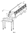
図2は、図示されていない固定天井の下に吊り下げられたパネル1のフレーム4に布帛5を取り付けるための本発明の方法を示す。パネル1は、固定天井の下の取り付け位置で示されているが、取り付けに使用される取付具または要素は図示されておらず、さらに、説明の便宜上、固定天井も図示されていない。パネルは、ワイヤ、ブラケット等を使用するなど、任意の適切な方法で固定天井の下に吊り下げられ得る。図2はパネル1の一部のみを示していることに留意されたい。パネル1の一部は、線IV−IVに沿って切り取られている。さらに、図の右側のパネル1の反対側端部は切り取られている。図3では、パネル本体セクション46によって構成されたいくつかの細長パネル1および図示されていない周囲フレームが部屋の固定天井45の下にどのように配置され得るかが上から見た状態で示されている。説明の便宜上、固定天井45は透明として示されている。以下では、パネル1について詳細に説明し、続いて、パネル1のフレーム4への布帛5の取り付け方法について説明する。
FIG. 2 shows the method of the present invention for attaching the
図4および図5を参照すると、本発明のパネル1は上側2および下側3を有し、少なくとも実質的に剛性のフレーム4を含むことが分かる。図示されている実施形態では、フレーム4はパネル本体39上に取り付けられ、パネル本体39を取り囲む。フレーム4は、図12および図13に示されているように、隅部セクション36によって接続された4つの細長フレームセクション35によって構成される。細長フレームセクション35は、個々の細長フレームセクション35の接続部48によってパネル本体39に取り付けられる。パネル本体39は、例えば、遮音パネル、照明パネル、サーマルパネルであり得、あるいはパネル1が純粋に美的外観をもたらすことを意図している場合には、除外され得る。後者の場合、フレーム4は、自立型であり得、パネルを固定天井に取り付けるための取り付け手段を備え得る。フレーム4は長方形として図示されているが、フレーム4は代替形態として正方形、円形、楕円形などを含む他の形状を有し得ることは当業者には明らかである。
With reference to FIGS. 4 and 5, it can be seen that the
フレーム4の細長フレームセクション35は、好ましくは、押し出しアルミニウム形材から製造されるが、任意の適切な材料が使用され得る。締結ブラケット11は、好ましくは、折り曲げられた鋼から製造されるのが好ましいが、任意の適切な材料が使用され得る。
The
特定の用途に応じて、様々な異なる布帛または布地が布帛5に使用され得、布帛に関連する特性は、例えば、光および/または音に対する透過性および難燃性である。布帛5は、織物、または例えばガラス繊維のような任意の種類の適切な織物材料またはフォイルであり得る。
Depending on the particular application, a variety of different fabrics or fabrics may be used in the
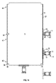
図12および図13を参照すると、本発明のパネル1のフレーム4の隅部セクション36の一実施形態が示されている。この実施形態の隅部セクション36には、フレーム4の細長フレームセクション35の対応する形材に挿入するための延長部が設けられる。隅部セクション36への布帛5の取り付けを容易にするために、隅部セクションには、布帛5の隅部の部分を挿入するための溝37が設けられ得、布帛のこの部分はさらに、弾性部材38(例えば、適切な直径の可撓コード片)によって溝37内で保持され得る。当然、他の保持手段も考えられる。隅部セクション36は、現場でフレームの組み立てまたは分解を可能にし、ひいてはフレーム4の輸送を容易にする。
With reference to FIGS. 12 and 13, one embodiment of the
再び図4および図5を参照すると、布帛5は、フレーム4の下側6で張り渡されるように構成され、そのため布帛5がパネル1の下側3を形成することが分かる。フレーム4は、布帛5が張り渡される下方周縁部7を有し、布帛5の縁部8は、フレームの下方周縁部7の上方でフレーム4の外周側9に設けられた突起部を把持するフック状要素13によって、フレーム4の外周側9に解放可能に取り付けられる。図4の布帛5の伸張状態では、布帛5の縁部8はフレームの下方周縁部7の上方に位置する装着位置10に位置決めされることに留意されたい。したがって、フレーム4全体は、フレームが配置される部屋の床に立っている人に対して少なくとも実質的に隠れた状態になり得る。布帛の縁部8は、布帛5の縁部8に沿って配置されたいくつかの締結ブラケット11によってフレーム4の外周側9に取り付けられ、締結ブラケット11は、第1のステップにおいて、図5に示されているように、布帛5がフレーム4の下で緩んだ状態でぶら下がっている第1の下方位置15で、第2のステップにおいて、図4に示されているように、布帛5がフレーム4の下側6で張り渡される第2の上方位置16で、フレーム4の外周側9に取り付けられる。図示されているように、締結ブラケット11の第1の下方位置15において、締結ブラケット11のフック状要素13は、フレーム4の外周側9に設けられた第1の下方突起部17を把持し、締結ブラケット11の第2の上方位置16において、締結ブラケット11のフック状要素13は、フレーム4の外周側9に設けられた第2の上方突起部18を把持する。図示されている実施形態では、第1の下方突起部17および第2の上方突起部18は、細長フレームセクション35を形成する押出形材の一体部分として形成されることが分かる。しかしながら、第1の下方突起部17および第2の上方突起部18は、締結ブラケット11のフック状要素13がこれらの突起部を適切に把持するために、任意の適切な形態を有し得る。さらに、図示されている実施形態では、第1の下方突起部17および第2の上方突起部18は連続した突起部として形成されているが、これらは細長フレームセクション35に沿って配置されたいくつかの別個々の要素としても形成され得る。
With reference to FIGS. 4 and 5 again, it can be seen that the
図4および図5に示されているように、各締結ブラケット11は、フック状要素13が配置される第1の上端部12と、支持要素19が配置される第2の下端部14とを有し、支持要素19は、図5に示されている締結ブラケット11の第1の下方位置15および図4に示されている締結ブラケット11の第2の上方位置16の両方でフレーム4に当接するように構成される。締結ブラケット11の第1の上端部12および第2の下端部14の定義は、図4および図5にそれぞれ示されているように、締結ブラケット11が第2の上方位置または第1の下方位置16にあるときの締結ブラケット11の位置および向きに関係することに留意されたい。さらに、支持要素19は、締結ブラケット11の第1の下方位置において、フレーム4の縁部の下で把持するように構成されることが分かる。図示されている実施形態では、前記縁部はフレーム4の下方周縁部7でもある。しかしながら、他の実施形態では、前記縁部はフレームの下方周縁部7の上方に配置された別個の縁部であり得る。
As shown in FIGS. 4 and 5, each
図示されている実施形態では、布帛5の縁部8は、少なくとも1つのばね25によって各締結ブラケット11の第1の上端部12に取り付けられる。ばね25は、他の位置で締結ブラケット11に取り付けられ得るが、ばね25を締結ブラケット11の第1の上端部12に取り付けることで、図4に示されているように、締結ブラケット11は、フレーム4の第2の上方突起部18にぶら下がっているときに、より安定して把持することができる。
In the illustrated embodiment, the
さらに、布帛5の縁部8は、布帛5の縁部8に沿って取り付けられた細長形材26によって少なくとも1つのばね25に取り付けられる。少なくとも1つのばね25は、締結ブラケット11の第1の下方位置15において、細長形材26の縁部20を締結ブラケット11の溝21内で保持するように構成される。
Further, the
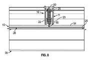
図6を参照すると、締結ブラケット11は、少なくとも締結ブラケット11の第1の下方位置15において、少なくとも1つのばね25を締結ブラケット11の長手方向に案内するように構成され、前記長手方向は、締結ブラケット11の第1の上端部12から第2の下端部14へと延びる方向である。図示されている実施形態では、少なくとも1つのばね25の前記案内は、締結ブラケット11が締結ブラケット11の2つの側壁22、23間に少なくとも1つのばね25を引き込むように構成されるということで達成される。図8において、図示されている実施形態では、少なくとも1つのばね25も同様に、締結ブラケット11の第2の上方位置16において2つの側壁22、23間に案内されることが分かる。
Referring to FIG. 6, the
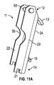
特に図11Aおよび図11Bにおいて、図示されている実施形態では、締結ブラケット11は、中央壁24と2つの側壁22、23とを有し、第1の上端部12と第2の下端部14との間で長手方向に延びるU字形形材を形成するように折り曲げられた板材から形成される。U字形形材の断面を見たときに、中央壁24はU字形断面の底部を形成し得、2つの側壁22、23はU字形断面の側面を形成し得る。さらに、フック状要素13は、U字形形材の中央壁24の上端部から折り曲げられたフラップとして形成され、支持要素19は、U字形形材の中央壁24の下端部から折り曲げられたフラップとして形成されていることが分かる。図から分かるように、フック状要素13を形成するフラップおよび支持要素19を形成するフラップは、2つの側壁22、23が中央壁24から折り曲げられる方向に対して少なくとも実質的に反対方向に中央壁24から折り曲げられる。当然、フック状要素13および支持要素19は、図示されているものとは異なる構成を有し得る。例えば、支持要素19は、単に、フレーム4に当接するように構成される中央壁24の領域または部分であり得る。さらに、図7および図8において、ばね25の第1の端部52は、U字形形材の第1の上端部12においてU字形形材の2つの側壁22、23間に延びるピン50に取り付けられ、ばね25の第2の端部53は、布帛5の縁部8に沿って取り付けられた細長形材26の縁部20に取り付けられる。さらに、図4〜図11では、溝21は、U字形形材の第2の下端部14においてU字形形材の2つの側壁22、23のそれぞれの下端部に形成されていること、および細長形材26の縁部20が前記溝21に嵌合することが分かる。ばね25は、例えば、図6に示されているように、細長形材26の縁部20を前記溝21内で保持するよう構成される。したがって、ばね25は、U字形形材の2つの側壁22、23間で細長形材26の縁部20に取り付けられる。締結ブラケット11の各壁23、24の切り欠き56は、特に、締結ブラケットが第1の下方位置15から第2の上方位置16まで持ち上げられなければならないときに、2本の指で締結ブラケット11を把持するのを容易にし得る。
In particular, in the illustrated embodiments of FIGS. 11A and 11B, the
図4および図5に示されているように、布帛5の縁部8は、布帛5の縁部8に沿った肥厚領域27を把持する細長形材26によって締結ブラケット11に取り付けられる。細長形材26は、布帛5が延びる長手方向延長スリット29を有する管状断面28を有し、細長形材26は少なくとも1つのばね25によって締結ブラケット11に取り付けられる。布帛5の縁部8に沿った肥厚領域27は、内側に紐31またはロッドを有するヘム30によって形成される。細長形材26は、特に図7に分かりやすく示されており、細長形材26および肥厚領域27は、図9に断面図で示されている。さらに、細長形材26と肥厚領域27との接続手順が図14に示されている。
As shown in FIGS. 4 and 5, the
また、図14に示されているように、布帛5の縁部8に沿った肥厚領域27は、布帛5の縁部8の互いに離間した切れ込み32によって分断される。そのため、細長形材26のいくつかを、布帛の縁部の切れ込み32を通って布帛5の縁部8に沿った肥厚27領域に滑り込ませることができる。このことは、細長形材が布帛の縁部に沿って滑り込む距離が長すぎるのを回避することができるので、細長形材26を布帛5の縁部8に取り付けるのを容易にし得る。さらに、布帛5の縁部8に沿った肥厚領域27は、布帛5の隅部34にある布帛5の縁部8の隅部切れ込み33によって分断される。したがって、細長形材26の少なくともいくつかを、前記隅部切れ込み33を通って布帛5の縁部8に沿った肥厚領域27に滑り込ませることができる。同時に、隅部切れ込み33は、隅部34に布帛が寄りすぎるのを回避するのに役立ち得、この切れ込み33がなければ所望の審美的外観を損なう望ましくない折り目または皺をもたらす可能性がある。
Further, as shown in FIG. 14, the thickened
図示されている実施形態では、布帛の縁部8は、各々の細長フレームセクション35に沿って配置された少なくとも2つの締結ブラケット11によってフレーム4の外周側9に取り付けられるように構成される。したがって、以下の取り付け手順の説明から理解されるように、比較的大型のフレームへの布帛の取り付けが容易になり得る。
In the illustrated embodiment, the
さらに、締結ブラケット11が第1の下方位置15にあるとき、締結ブラケット11に取り付けられた布帛5の縁部8はフレーム4の下方周縁部7の下方に位置決めされる。そのため、布帛5を取り外すことなく、布帛の上およびフレーム4の内側の領域に接近することができる。これは、例えば、フレーム4の内側に設けられたパネル本体39が照明パネルである、または照明パネルを含む場合に有利であり得る。この場合、布帛を取り外すことなく照明パネルを修理することができる。さらに、布帛5の上側の塵埃は、照明が点灯されているときに下から特に目に見えることがあり、したがって、最初に布帛5を取り外すことなく塵埃を除去することができるようにパネル1の内側に容易に接近できることが有利であり得る。
Further, when the
図2を参照しながら、パネル1のフレーム4に布帛5を取り付ける方法を以下に説明する。布帛5は、フレームが天井の取り付け位置に配置された後に、布帛5のロール40を台車41上に配置し、布帛5が布帛5のロール40から徐々に繰り出されるにつれて少なくとも実質的に剛性のフレーム4に沿って台車を動かすことによって、少なくとも実質的に剛性のフレーム4に取り付けられる。ロール40は、布帛5の縁部8に沿って予め形成された肥厚領域27を有する布帛5のロールである。
A method of attaching the
布帛5は、最初に、部分的に繰り出されたロール40の布帛の自由端である布帛5の第1の端部42をいくつかの締結ブラケット11に取り付けて、前記締結ブラケットをフレーム4の外周側9に解放可能に係合させ、次に、布帛5の中間部分43をいくつかの締結ブラケット11に取り付けて、前記締結ブラケットをフレーム4の外周側9に解放可能に係合させ、その後に、布帛5の第2の端部44をいくつかの締結ブラケット11に取り付けて、前記締結ブラケットをフレーム4の外周側9に解放可能に係合させることによって、少なくとも実質的に剛性のフレーム4に取り付けられる。
The
いずれかの締結ブラケット11が第1の下方位置15から第2の上方位置16へと再配置される前に、布帛5を取り付けるのに必要な全ての締結ブラケット11を第1の下方位置でフレーム4の外周側9に解放可能に係合させる。したがって、布帛が最終的にフレーム4上で張力が付与されて張り渡される前に、確実に、布帛5全体が正確に配置され、塵埃がない状態になり得る。そのため、繰り返しの修正手順を回避することができ、布帛5の取り付けの間の時間を節約することができる。その後、締結ブラケットは、1つずつ第1の下方位置から第2の上方位置へと再配置されて、布帛を適切に張り渡すことができる。
Before any
図14は、繰り出された既製布帛の上面図である。図示されているように、各締結ブラケット11とそれに対応する細長形材26とは、結合ユニットとして布帛の縁部に取り付けられている。したがって、締結ブラケット11を第1の下方位置でフレーム4に取り付けることによる、その後の布帛の取り付けが容易になり得る。締結ブラケット11とそれに対応する細長形材26とは、例えば、図6に示されているように、細長形材26の縁部20を締結ブラケット11の溝21内で保持する少なくとも1つのばね25によって、結合ユニットとして一緒に保持される。この状態では、締結ブラケット11とそれに対応する細長形材26との間の接続力を付与するために、少なくとも1つのばね25が少なくともわずかに延ばされる。好ましくは、布帛5を細長形材26に取り付ける前に、少なくとも1つのばね25に、細長形材26の縁部20を締結ブラケット11の溝21内で保持させる。実際に、各締結ブラケット11およびそれに対応する細長形材26は、結合ユニットとして工場から出荷され得る。したがって、取り付け手順が容易になり得る。
FIG. 14 is a top view of the unwound ready-made fabric. As shown, each
取り付け手順の間に、締結ブラケット11が第1の下方位置15から第2の上方位置16へと再配置されるときに、少なくとも1つのばね25が、例えば、図4および図8に示すように延ばされる。そのため、適切な永久的伸張力が布帛に加えられ得る。その結果、確実に布帛が適切に張り渡され得る。
During the mounting procedure, when the
取り付け手順の間、布帛5の中間部分43は、布帛5の縁部8の切れ込み32を通して布帛5の縁部8に沿った肥厚領域27に細長形材26を滑り込ませることによって、少なくともいくつかの締結ブラケット11に取り付けられる。そのため、細長形材26が布帛5の縁部8に沿って滑り込む距離が長すぎるのを回避することができる。
During the attachment procedure, the
図示されている実施形態では、締結ブラケット11は、曲げ加工によって金属板から形成される。しかしながら、代替として、締結ブラケット11は、射出成形され得る。この場合、適切には、締結ブラケット11は、異なる製造手順に適合した形態を有し得る。同様に、図示されている実施形態では、細長形材26は比較的短い形材の形態を有する。しかしながら、代替として、各細長形材26は、場合により、第1の隅部セクション36から第2の隅部セクション36までの細長フレームセクション35の3分の1の長さ、2分の1の長さ、または全長にわたって延びる、より長い形材の形態を有し得る。
In the illustrated embodiment, the
単に一例として、図3に示されている固定天井45は、30×60メートルとすることができ、パネル1は、ほぼ30メートルの長さとすることができる。細長形材26は、この場合、それぞれ40センチメートルの長さであり得る。細長形材26は、端部が細長フレームセクション35に沿って互いにほぼ当接して配置され得る、または離間され得る。好ましくは、細長形材26は、数センチメートルだけ離間される。しかしながら、布帛の性質および肥厚領域27の堅さに応じて、細長形材26は、互いにより長い間隔、例えば、50センチメートル、さらには1メートル以上、離間され得る。切れ込み32は、例えば、約3メートルだけ互いに離間して位置決めされ得る。ヘム30の紐31は、例えば、3〜4ミリメートルの直径を有し、ポリエステルまたはガラス繊維製のケーブルまたはワイヤであり得る。
As merely an example, the fixed
1 パネル
2 パネルの上側
3 パネルの下側
4 フレーム
5 布帛
6 フレームの下側
7 フレームの下方周縁部
8 布帛の縁部
9 フレームの外周側
10 装着位置
11 締結ブラケット
12 締結ブラケットの第1の上端部
13 締結ブラケットのフック状要素
14 締結ブラケットの第2の下端部
15 締結ブラケットの第1の下方位置
16 締結ブラケットの第2の上方位置
17 フレームの外周側にある第1の下方突起部
18 フレームの外周側にある第2の上方突起部
19 締結ブラケットの支持要素
20 細長形材の縁部
21 締結ブラケットの溝
22 締結ブラケットのU字形形材の第1の側壁
23 締結ブラケットのU字形形材の第2の側壁
24 締結ブラケットのU字形形材の中央壁
25 ばね
26 細長形材
27 肥厚領域
28 細長形材の管状断面
29 細長形材の管状断面の長手方向延長スリット
30 ヘム
31 紐
32 切れ込み
33 隅部切れ込み
34 布帛の隅部
35 細長フレームセクション
36 隅部セクション
37 隅部セクションの溝
38 弾性部材
39 パネル本体
40 布帛のロール
41 台車
42 布帛の第1の端部
43 布帛の中間部分
44 布帛の第2の端部
45 部屋の固定天井
46 パネル本体セクション
47 フレームセクションの補強リブ
48 フレームセクションの接続部
49 フレームセクションの斜め下方部
50 ピン
51 穴
52 ばねの第1の端部
53 ばねの第2の端部
54 細長形材の平坦な部分
55 ばね用の接続穴
56 締結ブラケットの切り欠き
60 先行技術パネル
61 ワイヤ
62 作業台
1 Panel 2 Upper side of panel 3 Lower side of panel 4 Frame 5 Fabric 6 Lower side of frame 7 Lower peripheral edge of frame 8 Edge of fabric 9 Outer side of frame 10 Mounting position 11 Fastening bracket 12 First upper end of fastening bracket Part 13 Hook-shaped element of the fastening bracket 14 Second lower end of the fastening bracket 15 First lower position of the fastening bracket 16 Second upper position of the fastening bracket 17 First lower protrusion on the outer peripheral side of the frame 18 Frame 2nd upper protrusion on the outer peripheral side of the 19 Fastening bracket support element 20 Elongated shape member edge 21 Fastening bracket groove 22 First side wall of the U-shaped shape member of the fastening bracket 23 U-shaped shape member of the fastening bracket 2nd side wall 24 Central wall of U-shaped profile of fastening bracket 25 Spring 26 Elongated profile 27 Thickening area 28 Tubular cross section of elongated profile 29 Longitudinal extension slit 30 hem 31 String 32 Notch of tubular section of elongated profile 33 Corner notch 34 Cloth corner 35 Elongated frame section 36 Corner section 37 Corner section groove 38 Elastic member 39 Panel body 40 Cloth roll 41 trolley 42 Cloth first end 43 Cloth middle part 44 Cloth Second end 45 Room fixed ceiling 46 Panel body section 47 Frame section reinforcement ribs 48 Frame section connections 49 Frame section diagonally lower 50 Pins 51 Holes 52 Spring first end 53 Spring first End of 2 54 Flat part of elongated profile 55 Connection hole for spring 56 Notch of fastening bracket 60 Advanced technology panel 61 Wire 62 Workbench
Claims (29)
Applications Claiming Priority (1)
| Application Number | Priority Date | Filing Date | Title |
|---|---|---|---|
| PCT/IB2016/054105 WO2018007856A1 (en) | 2016-07-08 | 2016-07-08 | Panel for a suspended ceiling or the like and method of mounting a fabric on a frame of a suspended ceiling or the like |
Publications (3)
| Publication Number | Publication Date |
|---|---|
| JP2019521268A JP2019521268A (en) | 2019-07-25 |
| JP2019521268A5 JP2019521268A5 (en) | 2019-09-05 |
| JP6845319B2 true JP6845319B2 (en) | 2021-03-17 |
Family
ID=56413715
Family Applications (1)
| Application Number | Title | Priority Date | Filing Date |
|---|---|---|---|
| JP2019521197A Active JP6845319B2 (en) | 2016-07-08 | 2016-07-08 | How to attach the fabric to the panel for the suspended ceiling and the frame such as the suspended ceiling |
Country Status (11)
| Country | Link |
|---|---|
| US (1) | US10731342B2 (en) |
| EP (1) | EP3482011B1 (en) |
| JP (1) | JP6845319B2 (en) |
| KR (1) | KR102618795B1 (en) |
| CN (1) | CN109790712B (en) |
| AU (1) | AU2016413696B2 (en) |
| DK (1) | DK3482011T3 (en) |
| ES (1) | ES2815551T3 (en) |
| SA (1) | SA519400830B1 (en) |
| SG (1) | SG11201900877WA (en) |
| WO (1) | WO2018007856A1 (en) |
Families Citing this family (7)
| Publication number | Priority date | Publication date | Assignee | Title |
|---|---|---|---|---|
| US10731342B2 (en) | 2016-07-08 | 2020-08-04 | Kvadrat Soft Cells A/S | Panel for a suspended ceiling or the like and method of mounting a fabric on a frame of a suspended ceiling or the like |
| JP7003154B2 (en) * | 2017-05-08 | 2022-01-20 | クヴァドラ ソフト セルズ エー/エス | Architectural panels adapted to be mounted on the ceiling or the wall of a room, and how to make such architectural panels |
| DK3645946T3 (en) * | 2017-06-28 | 2021-07-12 | Price Industries Ltd | Thermally activated building panel |
| EP3802982B1 (en) * | 2018-05-29 | 2024-01-31 | Kvadrat Acoustics A/S | Building panel adapted to be mounted at a ceiling or wall of a room and method of manufacturing such building panel |
| FR3113940B1 (en) * | 2020-09-08 | 2022-08-12 | Scherrer Jean Marc | Condensation radiant device |
| DE102021122214A1 (en) | 2021-08-27 | 2023-03-02 | Richter Lighting Technologies Gmbh | Device and method for tensioning at least one length of fabric |
| FR3140638A1 (en) | 2022-10-05 | 2024-04-12 | Newmat | Profiled element for stretched canvas slab and slab comprising such a profiled element |
Family Cites Families (26)
| Publication number | Priority date | Publication date | Assignee | Title |
|---|---|---|---|---|
| JPS5548011Y2 (en) * | 1974-12-16 | 1980-11-11 | ||
| DE3243525A1 (en) * | 1982-11-25 | 1984-05-30 | Max Dipl.-Ing. Dr.-Ing. 8700 Würzburg Mengeringhausen | System for fixing thin-walled flexible skins, e.g. foils, fabrics and the like, to a statically bearing substructure |
| FR2630476B1 (en) | 1988-04-22 | 1990-08-24 | Scherrer Fernand | FALSE-CEILING CONSISTING OF A TENSIONED CLOTH HANGED ALONG ITS EDGES, TO A SUPPORT FIXED TO THE WALLS OF A PIECE OF A BUILDING |
| EP0597094B1 (en) | 1991-01-10 | 1997-05-14 | Scs Promotion Company Limited | Sheet stretcher |
| JP2001020442A (en) * | 1999-07-09 | 2001-01-23 | Ibiden Co Ltd | Interior finishing construction |
| JP4369031B2 (en) * | 2000-10-17 | 2009-11-18 | 株式会社エービーシー商会 | Shade and support frame |
| JP2002194848A (en) * | 2000-12-26 | 2002-07-10 | Taiyo Kogyo Corp | Opening-closing part support structure of membrane ceiling panel |
| JP4693273B2 (en) * | 2001-04-25 | 2011-06-01 | 太陽工業株式会社 | FILM MATERIAL FIXING UNIT STRUCTURE, FIXING METHOD, AND FILM MATERIAL FIXING STEEL USED FOR THEM |
| DE10253343A1 (en) | 2002-11-14 | 2004-05-27 | Der Kluth: Decke Und Licht Gmbh | Stretched-foil wall or ceiling cover comprises a frame made up of profiles whose lower section is shaped so that its free edge forms an outer boundary of the visible foil area |
| FR2864566B1 (en) * | 2003-12-24 | 2006-03-17 | Jean Marc Scherrer | FALSE TENDERED CANVAS WALLS MEET BY AN INCLINED SEPARATOR |
| DK2048299T3 (en) * | 2004-01-28 | 2017-07-31 | Soft Cells As | Covering panel, especially for suspended ceilings |
| ATE422223T1 (en) * | 2004-01-28 | 2009-02-15 | Soft Cells As | CEILING ELEMENTS AND ARRANGEMENTS OF SUCH CEILING ELEMENTS FOR SUSPENDED CEILINGS |
| US7650923B2 (en) * | 2004-04-16 | 2010-01-26 | Morris Milton A | Track assembly for supporting fabrics |
| FR2892739B1 (en) * | 2005-11-03 | 2008-01-18 | Newmat Sa Sa | PROFILE FOR EMPTY FRAME |
| FR2926100B1 (en) * | 2008-01-09 | 2010-03-19 | Normalu | SYSTEM FOR ATTACHING WALLS OR CEILINGS TENDUED BY MEANS OF SMALL SIZE |
| FR2934284B1 (en) * | 2008-07-22 | 2010-09-10 | Newmat | PROFILE BENDING MEANS FOR EMPTY FRAME |
| AT507399B1 (en) | 2008-10-13 | 2010-09-15 | Schnurrer Anton | LAMP |
| KR101086354B1 (en) * | 2009-09-09 | 2011-11-23 | 주식회사 코시스홀딩스 | installation structure of sheet for ceiling finish |
| AT509175B1 (en) | 2009-11-16 | 2016-04-15 | Schnurrer Anton | LIGHT BLANKET |
| KR101234678B1 (en) * | 2010-11-05 | 2013-02-19 | 김종화 | Ceiling materials installation structure |
| FR3010424B1 (en) * | 2013-09-10 | 2015-09-25 | Normalu | <P> FASTENING SYSTEM FOR REALIZED COATINGS </ P> |
| JP6216661B2 (en) * | 2014-02-28 | 2017-10-18 | 協立工業株式会社 | Membrane ceiling fixing unit |
| CN203834784U (en) * | 2014-04-09 | 2014-09-17 | 中建城市建设发展有限公司 | Round light transmission flexible film suspended ceiling |
| DE202014104186U1 (en) | 2014-09-05 | 2015-09-08 | Sefar Ag | light unit |
| FR3053709B1 (en) * | 2016-07-06 | 2019-10-18 | Normalu Sas | LUMINOUS LOWERING DEVICE |
| US10731342B2 (en) | 2016-07-08 | 2020-08-04 | Kvadrat Soft Cells A/S | Panel for a suspended ceiling or the like and method of mounting a fabric on a frame of a suspended ceiling or the like |
-
2016
- 2016-07-08 US US16/315,902 patent/US10731342B2/en active Active
- 2016-07-08 KR KR1020197003641A patent/KR102618795B1/en active IP Right Grant
- 2016-07-08 CN CN201680089001.5A patent/CN109790712B/en active Active
- 2016-07-08 WO PCT/IB2016/054105 patent/WO2018007856A1/en unknown
- 2016-07-08 JP JP2019521197A patent/JP6845319B2/en active Active
- 2016-07-08 DK DK16739264.6T patent/DK3482011T3/en active
- 2016-07-08 SG SG11201900877WA patent/SG11201900877WA/en unknown
- 2016-07-08 EP EP16739264.6A patent/EP3482011B1/en active Active
- 2016-07-08 AU AU2016413696A patent/AU2016413696B2/en active Active
- 2016-07-08 ES ES16739264T patent/ES2815551T3/en active Active
-
2019
- 2019-01-08 SA SA519400830A patent/SA519400830B1/en unknown
Also Published As
| Publication number | Publication date |
|---|---|
| SG11201900877WA (en) | 2019-02-27 |
| SA519400830B1 (en) | 2022-05-08 |
| AU2016413696B2 (en) | 2021-08-19 |
| EP3482011A1 (en) | 2019-05-15 |
| ES2815551T3 (en) | 2021-03-30 |
| US20190249428A1 (en) | 2019-08-15 |
| AU2016413696A1 (en) | 2019-02-28 |
| KR102618795B1 (en) | 2023-12-29 |
| CN109790712B (en) | 2020-12-25 |
| JP2019521268A (en) | 2019-07-25 |
| DK3482011T3 (en) | 2020-09-21 |
| KR20190046781A (en) | 2019-05-07 |
| US10731342B2 (en) | 2020-08-04 |
| CN109790712A (en) | 2019-05-21 |
| WO2018007856A1 (en) | 2018-01-11 |
| EP3482011B1 (en) | 2020-06-17 |
Similar Documents
| Publication | Publication Date | Title |
|---|---|---|
| JP6845319B2 (en) | How to attach the fabric to the panel for the suspended ceiling and the frame such as the suspended ceiling | |
| US7954293B2 (en) | Panels and systems of such panels for instance for suspended ceilings | |
| US7673665B2 (en) | Cordless flexible window covering | |
| US20110145987A1 (en) | Hanging shower curtain support | |
| WO2007016616A2 (en) | Raisable panel | |
| JP2019521268A5 (en) | ||
| US2739644A (en) | Window cornice | |
| KR200400101Y1 (en) | Clip structure for rail of blind | |
| KR101371645B1 (en) | Structure of stretch sheet for building | |
| RU59094U1 (en) | TOWEL FASTENING BAGUETTE | |
| CA2371461A1 (en) | Apparatus and method for assembling sheet material mounting device components | |
| KR101797048B1 (en) | A barcket for mounting a screen louver to the ceiling surface or wall of a building | |
| CN219733259U (en) | Antistatic roller shutter | |
| JPH0742463A (en) | Pleated curtain | |
| JP2015101903A (en) | Roll screen device, and installation method of the roll screen device | |
| CN215761419U (en) | Glass window with built-in roller shutter | |
| EP1914361A1 (en) | Outdoor framework structure for awnings | |
| JP4596387B2 (en) | Attaching method of awning sheet and woven / knitted sheet for awning sheet | |
| JP3117295U (en) | Clothes drying unit | |
| JP7117815B2 (en) | Suspension hook and suspension structure of sheet material | |
| US20230250690A1 (en) | Adjustable valance system | |
| CA2733848A1 (en) | Support bracket for mounting an end of a roller blind | |
| JP2010216112A (en) | Device for opening and closing curing sheet | |
| KR200237756Y1 (en) | Placard A Rack System | |
| JP2862818B2 (en) | Lift curtains and their rails, string guides and mounting means |
Legal Events
| Date | Code | Title | Description |
|---|---|---|---|
| A529 | Written submission of copy of amendment under article 34 pct |
Free format text: JAPANESE INTERMEDIATE CODE: A529 Effective date: 20190304 |
|
| A521 | Request for written amendment filed |
Free format text: JAPANESE INTERMEDIATE CODE: A523 Effective date: 20190703 |
|
| A621 | Written request for application examination |
Free format text: JAPANESE INTERMEDIATE CODE: A621 Effective date: 20190703 |
|
| A977 | Report on retrieval |
Free format text: JAPANESE INTERMEDIATE CODE: A971007 Effective date: 20200714 |
|
| A131 | Notification of reasons for refusal |
Free format text: JAPANESE INTERMEDIATE CODE: A131 Effective date: 20200716 |
|
| A521 | Request for written amendment filed |
Free format text: JAPANESE INTERMEDIATE CODE: A523 Effective date: 20201016 |
|
| TRDD | Decision of grant or rejection written | ||
| A01 | Written decision to grant a patent or to grant a registration (utility model) |
Free format text: JAPANESE INTERMEDIATE CODE: A01 Effective date: 20210129 |
|
| A61 | First payment of annual fees (during grant procedure) |
Free format text: JAPANESE INTERMEDIATE CODE: A61 Effective date: 20210225 |
|
| R150 | Certificate of patent or registration of utility model |
Ref document number: 6845319 Country of ref document: JP Free format text: JAPANESE INTERMEDIATE CODE: R150 |
|
| R250 | Receipt of annual fees |
Free format text: JAPANESE INTERMEDIATE CODE: R250 |