JP6844004B2 - Drive device for window glass open / close adjustment device with bearing elements for fixing the stator in the housing - Google Patents
Drive device for window glass open / close adjustment device with bearing elements for fixing the stator in the housing Download PDFInfo
- Publication number
- JP6844004B2 JP6844004B2 JP2019533679A JP2019533679A JP6844004B2 JP 6844004 B2 JP6844004 B2 JP 6844004B2 JP 2019533679 A JP2019533679 A JP 2019533679A JP 2019533679 A JP2019533679 A JP 2019533679A JP 6844004 B2 JP6844004 B2 JP 6844004B2
- Authority
- JP
- Japan
- Prior art keywords
- drive
- housing
- stator
- worm
- rotor
- Prior art date
- Legal status (The legal status is an assumption and is not a legal conclusion. Google has not performed a legal analysis and makes no representation as to the accuracy of the status listed.)
- Active
Links
- 239000005357 flat glass Substances 0.000 title claims description 18
- 230000005291 magnetic effect Effects 0.000 claims description 53
- 238000003466 welding Methods 0.000 claims description 2
- 230000004323 axial length Effects 0.000 description 7
- 230000005540 biological transmission Effects 0.000 description 6
- 230000005284 excitation Effects 0.000 description 5
- 230000002093 peripheral effect Effects 0.000 description 5
- 238000007789 sealing Methods 0.000 description 5
- 238000004804 winding Methods 0.000 description 4
- 241001074085 Scophthalmus aquosus Species 0.000 description 3
- 239000000463 material Substances 0.000 description 3
- 238000000465 moulding Methods 0.000 description 3
- 230000009977 dual effect Effects 0.000 description 2
- 238000004519 manufacturing process Methods 0.000 description 2
- 229910052751 metal Inorganic materials 0.000 description 2
- 239000002184 metal Substances 0.000 description 2
- 238000000926 separation method Methods 0.000 description 2
- 229920003002 synthetic resin Polymers 0.000 description 2
- 239000000057 synthetic resin Substances 0.000 description 2
- 241001416181 Axis axis Species 0.000 description 1
- 229910052684 Cerium Inorganic materials 0.000 description 1
- 238000004026 adhesive bonding Methods 0.000 description 1
- GWXLDORMOJMVQZ-UHFFFAOYSA-N cerium Chemical compound [Ce] GWXLDORMOJMVQZ-UHFFFAOYSA-N 0.000 description 1
- 238000002788 crimping Methods 0.000 description 1
- 238000006073 displacement reaction Methods 0.000 description 1
- 230000002349 favourable effect Effects 0.000 description 1
- 230000005294 ferromagnetic effect Effects 0.000 description 1
- 239000003302 ferromagnetic material Substances 0.000 description 1
- WABPQHHGFIMREM-UHFFFAOYSA-N lead(0) Chemical compound [Pb] WABPQHHGFIMREM-UHFFFAOYSA-N 0.000 description 1
- 230000007257 malfunction Effects 0.000 description 1
- 239000007769 metal material Substances 0.000 description 1
- 238000000034 method Methods 0.000 description 1
- 229910001172 neodymium magnet Inorganic materials 0.000 description 1
- 230000000149 penetrating effect Effects 0.000 description 1
- 230000003014 reinforcing effect Effects 0.000 description 1
- 238000005096 rolling process Methods 0.000 description 1
- 230000007704 transition Effects 0.000 description 1
Images


Classifications
-
- E—FIXED CONSTRUCTIONS
- E05—LOCKS; KEYS; WINDOW OR DOOR FITTINGS; SAFES
- E05F—DEVICES FOR MOVING WINGS INTO OPEN OR CLOSED POSITION; CHECKS FOR WINGS; WING FITTINGS NOT OTHERWISE PROVIDED FOR, CONCERNED WITH THE FUNCTIONING OF THE WING
- E05F15/00—Power-operated mechanisms for wings
- E05F15/60—Power-operated mechanisms for wings using electrical actuators
- E05F15/603—Power-operated mechanisms for wings using electrical actuators using rotary electromotors
- E05F15/665—Power-operated mechanisms for wings using electrical actuators using rotary electromotors for vertically-sliding wings
- E05F15/689—Power-operated mechanisms for wings using electrical actuators using rotary electromotors for vertically-sliding wings specially adapted for vehicle windows
- E05F15/697—Motor units therefor, e.g. geared motors
-
- H—ELECTRICITY
- H02—GENERATION; CONVERSION OR DISTRIBUTION OF ELECTRIC POWER
- H02K—DYNAMO-ELECTRIC MACHINES
- H02K21/00—Synchronous motors having permanent magnets; Synchronous generators having permanent magnets
- H02K21/12—Synchronous motors having permanent magnets; Synchronous generators having permanent magnets with stationary armatures and rotating magnets
- H02K21/22—Synchronous motors having permanent magnets; Synchronous generators having permanent magnets with stationary armatures and rotating magnets with magnets rotating around the armatures, e.g. flywheel magnetos
-
- H—ELECTRICITY
- H02—GENERATION; CONVERSION OR DISTRIBUTION OF ELECTRIC POWER
- H02K—DYNAMO-ELECTRIC MACHINES
- H02K7/00—Arrangements for handling mechanical energy structurally associated with dynamo-electric machines, e.g. structural association with mechanical driving motors or auxiliary dynamo-electric machines
- H02K7/08—Structural association with bearings
- H02K7/081—Structural association with bearings specially adapted for worm gear drives
-
- H—ELECTRICITY
- H02—GENERATION; CONVERSION OR DISTRIBUTION OF ELECTRIC POWER
- H02K—DYNAMO-ELECTRIC MACHINES
- H02K1/00—Details of the magnetic circuit
- H02K1/06—Details of the magnetic circuit characterised by the shape, form or construction
- H02K1/12—Stationary parts of the magnetic circuit
- H02K1/18—Means for mounting or fastening magnetic stationary parts on to, or to, the stator structures
- H02K1/187—Means for mounting or fastening magnetic stationary parts on to, or to, the stator structures to inner stators
-
- H—ELECTRICITY
- H02—GENERATION; CONVERSION OR DISTRIBUTION OF ELECTRIC POWER
- H02K—DYNAMO-ELECTRIC MACHINES
- H02K2205/00—Specific aspects not provided for in the other groups of this subclass relating to casings, enclosures, supports
- H02K2205/03—Machines characterised by thrust bearings
-
- H—ELECTRICITY
- H02—GENERATION; CONVERSION OR DISTRIBUTION OF ELECTRIC POWER
- H02K—DYNAMO-ELECTRIC MACHINES
- H02K5/00—Casings; Enclosures; Supports
- H02K5/04—Casings or enclosures characterised by the shape, form or construction thereof
- H02K5/16—Means for supporting bearings, e.g. insulating supports or means for fitting bearings in the bearing-shields
- H02K5/161—Means for supporting bearings, e.g. insulating supports or means for fitting bearings in the bearing-shields radially supporting the rotary shaft at both ends of the rotor
-
- H—ELECTRICITY
- H02—GENERATION; CONVERSION OR DISTRIBUTION OF ELECTRIC POWER
- H02K—DYNAMO-ELECTRIC MACHINES
- H02K7/00—Arrangements for handling mechanical energy structurally associated with dynamo-electric machines, e.g. structural association with mechanical driving motors or auxiliary dynamo-electric machines
- H02K7/10—Structural association with clutches, brakes, gears, pulleys or mechanical starters
- H02K7/116—Structural association with clutches, brakes, gears, pulleys or mechanical starters with gears
- H02K7/1163—Structural association with clutches, brakes, gears, pulleys or mechanical starters with gears where at least two gears have non-parallel axes without having orbital motion
- H02K7/1166—Structural association with clutches, brakes, gears, pulleys or mechanical starters with gears where at least two gears have non-parallel axes without having orbital motion comprising worm and worm-wheel
Landscapes
- Engineering & Computer Science (AREA)
- Power Engineering (AREA)
- Connection Of Motors, Electrical Generators, Mechanical Devices, And The Like (AREA)
- Power-Operated Mechanisms For Wings (AREA)
- Window Of Vehicle (AREA)
- Motor Or Generator Frames (AREA)
Description
本発明は、請求項1の前提部分に記載した、車両の被覆要素を調整するための駆動装置、特に窓ガラス開閉調整装置のための駆動装置に関する。
The present invention relates to a drive device for adjusting a covering element of a vehicle, particularly a drive device for a window glass opening / closing adjustment device, which is described in the premise of
このような駆動装置は、被覆要素を調整するための出力要素と、電動機ユニットとを備えている。この電動機ユニットはステータと、ロータと、ロータに連結され軸の軸線回りに回転可能である、出力要素を駆動するための駆動軸とを有する電動機を備えている。電動機ユニットは少なくとも一部が駆動装置の駆動ハウジング内に入れられている。 Such a drive device includes an output element for adjusting the covering element and an electric motor unit. The motor unit comprises a stator, a rotor, and a motor having a drive shaft for driving an output element that is connected to the rotor and is rotatable about the axis of the shaft. At least a part of the electric motor unit is housed in the drive housing of the drive unit.
駆動装置は車両の被覆要素を調整するため、特に窓ガラス開閉調整装置のために有利に使用可能である。被覆要素は窓ガラス、スライドルーフ、荷物室カバー、テールゲート、日除けブラインドまたは車両の開口等を被覆するための車両ドアである。 Since the drive device adjusts the covering element of the vehicle, it can be advantageously used especially for the window glass opening / closing adjustment device. Covering elements are vehicle doors for covering windowpanes, sliding roofs, luggage compartment covers, tailgates, awning blinds or vehicle openings and the like.
窓ガラス開閉調整装置の場合、例えばドアモジュールの機器支持体に、1個または複数のガイドレールを配置することができる。このガイドレールに沿って、窓ガラスに連結された伝動体が1個ずつ案内されている。伝動体は(専ら)引張り力を伝達するように設計された可撓性の引張り要素(例えば引張りケーブル)を介して駆動装置に連結されている。この場合、引張り要素は、ケーブルドラムの回転運動時に引張り要素の一端がケーブルトラムに巻き取られ、他端がケーブルドラムから繰り出されるように、ケーブルドラムの形をした出力要素上に配置されている。それにより、引張りケーブルによって形成されたケーブルループを摺動させ、従ってそれぞれ付設されたガイドレールに沿って伝動体を移動させることになる。よって、例えば車両サイドドアの窓開口を開閉するために、窓ガラスを、駆動装置によって駆動して調整することができる。 In the case of the window glass opening / closing adjustment device, for example, one or a plurality of guide rails can be arranged on the device support of the door module. Along this guide rail, the transmitters connected to the window glass are guided one by one. The transmitter is connected to the drive via a flexible tensioning element (eg, a tensioning cable) designed to (exclusively) transmit the tensile force. In this case, the tension element is arranged on the output element in the shape of a cable drum so that one end of the tension element is wound around the cable tram and the other end is unwound from the cable drum during the rotational movement of the cable drum. .. As a result, the cable loop formed by the tension cable is slid, and thus the transmission body is moved along the guide rails attached to each of them. Therefore, for example, in order to open and close the window opening of the vehicle side door, the window glass can be driven and adjusted by a driving device.
独国特許出願公開第102004 044863A1号明細書から知られている、自動車の調整装置のための駆動装置の場合には、ケーブルドラムが駆動ハウジングの軸受心棒上に配置されている。この場合、駆動ハウジングはボルトの形をした固定要素を介して、機器支持体の形をした支持要素に連結されている。 In the case of a drive device for an automobile regulator, as known from German Patent Application Publication No. 102004 044863A1, the cable drum is located on the bearing mandrel of the drive housing. In this case, the drive housing is connected to a support element in the shape of an equipment support via a bolt-shaped fixing element.
窓ガラス開閉調整装置用の駆動装置は、例えば車両サイドドアのドアモジュールの機器支持体の形をした支持要素に取付けられ、それによって車両サイドドア内に入れられている。この駆動装置は、有利な運転特性、特に支持要素に対する励振作用が小さく回転がスムースであるという特性を有するべきであり、さらに供される構造スペースを効率的に利用すべきである。この場合、駆動装置をコンパクトに形成する必要がある。しかし、駆動装置は、調整すべき調整部品、例えば窓ガラスの確実な調整を保証するために、場合によってはシステムの機能不調の場合にも、例えばシール等内で回転し始めるために、十分なトルクを提供しなければならない。この場合一般的に、提供されるトルクは電動機の大きさに左右される。ロータ直径がより大きい場合および/またはロータ長さがより長い場合には、電動機はより大きなトルクを提供することができる。 The drive device for the window glass opening / closing adjustment device is attached to a support element in the form of a device support of a door module of a vehicle side door, for example, and is thereby housed in the vehicle side door. The drive should have advantageous operating characteristics, particularly low excitation on the supporting elements and smooth rotation, and should make efficient use of the structural space provided. In this case, it is necessary to form the drive device compactly. However, the drive unit is sufficient to ensure reliable adjustment of the adjustment parts to be adjusted, such as the windowpane, and in some cases even if the system malfunctions, to start rotating in, for example, a seal. Must provide torque. In this case, the torque provided generally depends on the size of the motor. If the rotor diameter is larger and / or the rotor length is longer, the motor can provide greater torque.
本発明の課題は、所望な運転特性を有し、十分なトルクを提供し、そしてコンパクトに形成することができる駆動装置を提供することである。 An object of the present invention is to provide a drive device which has desired driving characteristics, provides sufficient torque, and can be formed compactly.
この課題は、請求項1の特徴を有する対象によって解決される。
This problem is solved by an object having the characteristics of
それによれば、ステータは軸受要素を介して、駆動ハウジングの固定されたハウジング部分に連結され、軸受要素は軸受穴を有し、この軸受穴内に、駆動軸がステータと相対的に回転可能に軸承されている。 According to it, the stator is connected to a fixed housing portion of the drive housing via a bearing element, the bearing element has a bearing hole, and in the bearing hole, the drive shaft is rotatably supported relative to the stator. Has been done.
従って、軸受要素は使用されるときに二重機能を有する。軸受要素は一方では、駆動装置の駆動ハウジング内でステータを固定する働きをする。これは特に、後で詳しく説明するように、中央内側にある固定されたステータと、このステータを中心にその外側で回転するロータとを備えたアウタロータ電動機として電動機を形成することを可能にする。軸受要素はさらに、他の機能によって、駆動軸を軸承する働きをする。そのために、軸受要素は軸受穴を有し、この軸受穴内に、駆動軸がステータと相対的に回転可能に軸承されている。従って、軸受要素はステータと相対的に回転可能に軸承するための駆動軸用軸受を提供する。 Therefore, the bearing element has dual function when used. The bearing element, on the one hand, serves to secure the stator in the drive housing of the drive unit. This makes it possible, in particular, to form the motor as an outer rotor motor with a fixed stator located inside the center and a rotor that rotates around the stator, as will be described in detail later. Bearing elements also serve to support the drive shaft by other functions. Therefore, the bearing element has a bearing hole, and the drive shaft is rotatably supported in the bearing hole so as to be relatively rotatable with the stator. Therefore, the bearing element provides a drive shaft bearing for rotatably bearing relative to the stator.
軸受要素は例えば合成樹脂で作ることができる。軸受要素は特に、駆動軸を軸承するための滑り特性を有すると有利である。 The bearing element can be made of, for example, a synthetic resin. It is particularly advantageous for the bearing element to have slip properties for bearing the drive shaft.
実施形では、軸受要素はステータのステータ本体に固定連結された第1シャフト部分を有する。これに対して、第1シャフト部分に対して軸方向にずれている第2シャフト部分が、ハウジング部分に固定連結されているので、軸受要素はステータをハウジング部分に固定連結する。 In the embodiment, the bearing element has a first shaft portion that is fixedly connected to the stator body of the stator. On the other hand, since the second shaft portion displaced in the axial direction with respect to the first shaft portion is fixedly connected to the housing portion, the bearing element fixedly connects the stator to the housing portion.
実施形では、ロータは軸の軸線に関してステータの半径方向外側で回転するアウタロータとして形成されている。それによって、電動機ユニットの電動機はアウタロータ電動機として形成されている。このようなアウタロータ電動機の場合、固定されたステータが回転するロータの半径方向内側に配置されている。従って、ロータはステータ回りに回転する。これは、ロータを比較的に大きな直径で形成することを可能にする。これにより、電動機の所望なトルク特性を生じることができる。 In the embodiment, the rotor is formed as an outer rotor that rotates radially outward of the stator with respect to the axis of the shaft. As a result, the electric motor of the electric motor unit is formed as an outer rotor electric motor. In the case of such an outer rotor motor, the fixed stator is arranged inside the rotating rotor in the radial direction. Therefore, the rotor rotates around the stator. This allows the rotor to be formed with a relatively large diameter. This can produce the desired torque characteristics of the electric motor.
一般的に、電動機のトルクは直径が大きくなるにつれて増大する。従って、ロータの直径を大きくすると、これは、トルクが同じである場合、他の方向、特に軸方向における電動機の構造寸法を小さくするために用いることができ、よって電動機と駆動軸の軸方向長さを短縮することができる。 In general, the torque of an electric motor increases as the diameter increases. Therefore, increasing the diameter of the rotor can be used to reduce the structural dimensions of the motor in other directions, especially in the axial direction, given the same torque, and thus the axial length of the motor and drive shaft. Can be shortened.
電動機は特にブラシレス直流電動機として形成可能である。このようなブラシレス直流電動機の場合、ステータは一般的にステータ本体に多数の磁極歯を備え、この磁極歯には多数のステータコイルが配置されている。このようなステータコイルは例えば同心的なコイルとして磁極歯に巻くことができる。しかし、いわゆる軸コイルを使用してもよい。各磁極歯には1個または複数のコイルを配置することができる。この場合、各コイルは、付設の磁極歯の周りに巻かれた巻線によって形成された1つまたは複数の巻きからなっている。運転中、ステータコイルは、例えば三電流相をコイルに励起させて回転磁場をステータに発生するように、電子的に整流して通電される。 The electric motor can be particularly formed as a brushless DC motor. In the case of such a brushless DC motor, the stator generally has a large number of magnetic pole teeth on the stator body, and a large number of stator coils are arranged on the magnetic pole teeth. Such a stator coil can be wound around the magnetic pole teeth as, for example, concentric coils. However, a so-called shaft coil may be used. One or more coils may be arranged on each magnetic pole tooth. In this case, each coil consists of one or more windings formed by windings wound around the attached magnetic pole teeth. During operation, the stator coil is electronically rectified and energized so that, for example, a three-current phase is excited by the coil to generate a rotating magnetic field in the stator.
ブラシレス直流電動機の場合、ロータは多数の永久磁石極を有する磁石構造体を備えている。磁石構造体は例えば不連続の永久磁石によって形成可能である。しかし、軸の軸線の周りにおいて互いに周方向にずらされ交互に磁化される多数の磁石極を有する環状磁石を使用してもよい。例えば結合または焼結されたネオジム磁石構造体を使用することができる。さらに、Cer(セリウムとも呼ばれ、元素記号はCe)を(永久)磁石材料として用いる磁石構造体を使用してもよい。この磁石構造体に基づいて、ロータに励起磁場が存在する。この励起磁場は電動機の運転中、ロータにトルクを発生するためにステータの回転磁場と協働する。 For brushless DC motors, the rotor has a magnetic structure with a large number of permanent magnet poles. The magnet structure can be formed, for example, by a discontinuous permanent magnet. However, annular magnets having a large number of magnet poles that are circumferentially offset from each other and magnetized alternately around the axis of the axis may be used. For example, a bonded or sintered neodymium magnet structure can be used. Further, a magnet structure using Ce (also called cerium and the element symbol is Ce) as a (permanent) magnet material may be used. Based on this magnet structure, there is an excitation magnetic field in the rotor. This excitation magnetic field cooperates with the rotating magnetic field of the stator to generate torque in the rotor during the operation of the motor.
例示的な実施形では、ステータがステータコイルを配置した9個の磁極歯を備えている。ロータは例えば6個の(永久)磁石極(3対の磁石極)を有する磁石構造体を備えることができる。ブラシレス直流電動機を使用することにより、駆動装置はその運転特性およびトルク特性が所望であると共に、その形状をさらに小さくすることができる。 In an exemplary embodiment, the stator comprises nine magnetic pole teeth on which the stator coil is located. The rotor can include, for example, a magnet structure having six (permanent) magnet poles (three pairs of magnet poles). By using a brushless DC motor, the drive can be made smaller in shape as well as desired in its operating and torque characteristics.
実施形では、ロータは例えば強磁性材料で作られた磁極カップを備え、それによってロータに配置された磁石構造体のために磁気的なループバックを提供することができる。ロータは駆動軸に連結され、磁石構造体を支持する。この場合、磁石構造体は例えば環状磁石として磁極カップ内に配置されている。 In embodiments, the rotor may include, for example, a magnetic pole cup made of ferromagnetic material, thereby providing a magnetic loopback for the magnetic structure placed on the rotor. The rotor is connected to the drive shaft and supports the magnet structure. In this case, the magnet structure is arranged in the magnetic pole cup as, for example, an annular magnet.
駆動要素は好ましくは、駆動軸に歯でかみ合う駆動輪に作用連結されている。この場合、駆動軸は例えば駆動ウォームを支持している。この駆動ウォームは駆動輪の外歯とかみ合うウォーム歯を備えている。駆動軸を回転することによっておよびそれに伴い駆動ウォームを回転することによって、駆動輪が回転させられ、さらに出力要素が駆動される。 The drive element is preferably actuated and coupled to a drive wheel that is tooth-engaged with the drive shaft. In this case, the drive shaft supports, for example, a drive worm. This drive worm has worm teeth that mesh with the outer teeth of the drive wheels. By rotating the drive shaft and accompanying rotation of the drive worm, the drive wheels are rotated and the output elements are further driven.
この場合、ロータ、特にロータの磁極カップは好ましくは、駆動ウォームとは反対のステータの側で駆動軸に連結されている。それによって、ステータの外側でその回りを回転するロータの磁極カップは、駆動ウォームとは反対の側で、ステータを取り囲んでいる。これにより、駆動ウォーム寄りの側で軸受要素を介してステータを駆動ハウジングに連結し、駆動ウォームに対して空間的に近い位置関係で、軸受要素を介して駆動軸を軸承することができる。 In this case, the rotor, especially the magnetic pole cup of the rotor, is preferably connected to the drive shaft on the side of the stator opposite to the drive worm. Thereby, the magnetic pole cup of the rotor, which rotates around the outside of the stator, surrounds the stator on the opposite side of the drive worm. As a result, the stator can be connected to the drive housing via the bearing element on the side closer to the drive worm, and the drive shaft can be pivotally supported via the bearing element in a spatially close positional relationship with the drive worm.
駆動ハウジングは好ましくはウォームハウジングを備え、このウォームハウジング内に駆動ウォームが入れられている。ウォームハウジングは好ましくは、その軸方向長さに沿ってほぼ一定の直径を有する円筒の形に形成され、それによって駆動ウォームはウォームハウジング内に回転可能に収容されている。 The drive housing preferably comprises a worm housing in which the drive worm is housed. The worm housing is preferably formed in the form of a cylinder having a substantially constant diameter along its axial length, whereby the drive worm is rotatably housed within the worm housing.
実施形では、ウォームハウジングは軸受要素を連結したハウジング部分を形成している。そのために、軸受要素は例えばウォームハウジングに係合し、ウォームハウジングに固定連結されている。この固定連結は例えば、軸受要素をウォームハウジングに圧入することによって行われる。それに加えてまたはその代わりに、軸受要素をウォームハウジングに接着または溶接するかあるいはその他の方法でウォームハウジングに固定することができる。 In the embodiment, the worm housing forms a housing portion connecting bearing elements. To that end, the bearing element engages, for example, the worm housing and is fixedly connected to the worm housing. This fixed connection is performed, for example, by press-fitting the bearing element into the worm housing. In addition or instead, the bearing elements can be glued or welded to the worm housing or otherwise secured to the worm housing.
軸受要素はさらに、ステータの本体に固定連結されている。そのために、軸受要素を圧着、溶接、接着またはその他の方法でステータ本体に固定することができる。 The bearing element is further fixedly connected to the body of the stator. To that end, the bearing elements can be crimped, welded, glued or otherwise fixed to the stator body.
軸受要素をウォームハウジングに押し付けると、軸受要素はウォームハウジング内に圧入されてプレス嵌めされる。この場合、ウォームハウジング内で軸受要素の軸方向位置を定めるために、ウォームハウジングに段差部を設けることができる。軸受要素はウォームハウジング内への差込み(圧入)時に、例えば適当なストッパを介して段差部に接触する。それによって、軸受要素は連結状態でウォームハウジングに軸方向で支持される。 When the bearing element is pressed against the worm housing, the bearing element is press-fitted into the worm housing and press-fitted. In this case, a step portion may be provided in the worm housing in order to determine the axial position of the bearing element in the worm housing. When the bearing element is inserted (press-fitted) into the worm housing, the bearing element comes into contact with the step portion via, for example, an appropriate stopper. Thereby, the bearing elements are axially supported by the worm housing in a connected state.
異なる方法で軸受要素をウォームハウジングに連結する場合にも、軸受要素はウォームハウジングの段差部を介して、ウォームハウジングに対して所定の位置を占めることができる。 When the bearing elements are connected to the worm housing in different ways, the bearing elements can occupy a predetermined position with respect to the worm housing via the stepped portion of the worm housing.
軸受要素は駆動軸を軸承する働きをし、軸方向に比較的に長く形成可能であるので、駆動ハウジング内での駆動軸の所望な軸承が軸受要素を介して行われる。さらに、軸受要素に対して軸方向にずらした第2軸受要素を介して、駆動軸をウォームハウジング内で軸承することができる。この第2軸受要素は例えばステータとは反対側の駆動軸の端部に配置され、それによってステータから離れた端部で駆動軸はウォームハウジングに対して軸承する。この場合、第2軸受要素はブッシュ状に形成可能であり、そしてウォームハウジングに係合する第1軸受要素のシャフト部分と同じ外径を有することができる。それによって、第1軸受要素も第2軸受要素も例えばウォームハウジングにプレス嵌めすることができる。第1軸受要素と第2軸受要素がウォームハウジングの長さにわたって一定の内径を有する場合、第1軸受要素と第2軸受要素の外径が同じであると、許容誤差条件が有利になる。というのは、両軸受要素の装着部の許容誤差が同じようになるからである。 Since the bearing element acts to support the drive shaft and can be formed to be relatively long in the axial direction, the desired bearing of the drive shaft in the drive housing is performed via the bearing element. Further, the drive shaft can be pivotally supported in the worm housing via the second bearing element that is axially displaced with respect to the bearing element. The second bearing element is located, for example, at the end of the drive shaft on the opposite side of the stator so that the drive shaft pivots to the worm housing at the end away from the stator. In this case, the second bearing element can be formed in a bush shape and can have the same outer diameter as the shaft portion of the first bearing element that engages the worm housing. Thereby, both the first bearing element and the second bearing element can be press-fitted into, for example, a worm housing. When the first bearing element and the second bearing element have a constant inner diameter over the length of the worm housing, the same outer diameter of the first bearing element and the second bearing element makes the tolerance condition advantageous. This is because the tolerances of the mounting parts of both bearing elements are the same.
第2軸受要素は同様に、ウォームハウジングの第2段差部に軸方向で支持することが可能である。それによって、第2軸受要素はウォームハウジング内で所定の軸方向位置を占める。 Similarly, the second bearing element can be axially supported by the second step portion of the worm housing. Thereby, the second bearing element occupies a predetermined axial position in the worm housing.
駆動軸を軸方向で支持するために、ウォームハウジング内に例えば乗り上げ要素を設けることができる。駆動軸が(ステータとは反対側の)端部でこの乗り上げ要素に軸方向で支持される。乗り上げ要素は例えば、ウォームハウジングの端部分内に位置する。この端部分は駆動ウォームを収容するウォームハウジングの部分よりも小さな内径を有することができる。 For example, a riding element can be provided in the worm housing to support the drive shaft in the axial direction. The drive shaft is axially supported by this riding element at the end (opposite the stator). The riding element is located, for example, within the edge of the worm housing. This end portion can have a smaller inner diameter than the portion of the worm housing that houses the drive worm.
駆動軸は第1軸受要素を貫通するその端部において、ロータとステータを挿入した電動機カップの蓋に軸方向で支持することが可能である。そのために、この蓋に、駆動軸用スラスト軸受をなす乗り上げ個所を形成することができる。 The drive shaft can be axially supported by the lid of the motor cup into which the rotor and stator are inserted at its end penetrating the first bearing element. Therefore, a riding portion forming a thrust bearing for the drive shaft can be formed on the lid.
実施形では、駆動軸の軸線は、出力要素の回転軸線に対して傾斜した角度で配向可能である。例えば独国特許出願公開第102004 044863A1号明細書によって知られているような窓ガラス開閉調整装置用の従来の駆動装置の場合には、駆動軸の軸線が(ケーブルドラムの形をした)出力要素の回転軸線に対して横向きに延在している。出力要素に対する駆動軸のこの配置構造は、支持要素における駆動装置の電動機ユニットの配置可能性を制限するので、供される構造スペースが実質的に前もって定められる。この従来技術と異なり、駆動軸の軸線は出力要素の回転軸線に対して傾斜角度で配向される。従来は軸の軸線が出力要素の回転軸線に対して90°の角度をなしているのに対して、駆動軸の軸線は回転軸線に対して、傾斜角度、すなわち90未満の角度、例えば85°と65°の間の範囲の角度、例えば80°と70°の間の範囲の角度をなしている。これは付加的な自由度を提供する。というのは、これが、電動機ユニットの位置を駆動装置の他の構成要素に対して適合させることを可能にし、それによって供される構造スペースを効率的に利用することができるからである。 In the embodiment, the axis of the drive shaft can be oriented at an angle tilted with respect to the axis of rotation of the output element. For example, in the case of a conventional drive device for a window glass opening / closing adjustment device as known by German Patent Application Publication No. 102004 044863A1, the axis of the drive shaft is an output element (in the shape of a cable drum). It extends sideways with respect to the axis of rotation of. This arrangement of the drive shaft with respect to the output element limits the dispositionability of the motor unit of the drive on the support element, so that the structural space provided is substantially pre-determined. Unlike this prior art, the axis of the drive shaft is oriented at an angle of inclination with respect to the axis of rotation of the output element. Conventionally, the axis of the shaft forms an angle of 90 ° with respect to the rotation axis of the output element, whereas the axis of the drive shaft has an inclination angle with respect to the rotation axis, that is, an angle of less than 90, for example, 85 °. Angles in the range between and 65 °, for example angles in the range between 80 ° and 70 °. This provides additional degrees of freedom. This allows the position of the motor unit to be adapted to the other components of the drive, thereby making efficient use of the structural space provided.
これは、ロータの直径を(さらに)増大することを可能にする。直径の増大により、供されるトルクが同じである場合、電動機ユニットの軸方向長さとさらに駆動軸の軸方向長さを短縮することができる。これはさらに駆動装置のコンパクトな構造に寄与する。 This makes it possible to (further) increase the diameter of the rotor. By increasing the diameter, the axial length of the motor unit and the axial length of the drive shaft can be further shortened if the torques applied are the same. This further contributes to the compact structure of the drive.
好ましくは駆動輪の回転軸線に一致する、出力要素の回転軸線に対して、駆動軸の軸線を傾斜させたことにより、駆動ウォームも回転軸線に対して斜めに、ひいては駆動輪に対して斜めに延設することができる。有利な実施形では、軸の軸線の傾斜は、ウォーム歯のピッチ角度が軸の軸線と回転軸線に対して横向きに(90°の角度をなして)延びる横軸線との間の角度に一致するように選定される。これは、駆動輪の歯を直歯として形成することを可能にする。これにより、駆動輪を所望な形状にすることができると共に、簡単か
つ低コストで製作することができる。
By inclining the axis of the drive shaft with respect to the axis of rotation of the output element, which preferably coincides with the axis of rotation of the drive wheels, the drive worm is also oblique with respect to the axis of rotation and thus with respect to the drive wheels. It can be extended. In a favorable embodiment, the inclination of the axis of the axis coincides with the angle between the pitch angle of the worm teeth and the horizontal axis extending laterally (at an angle of 90 °) with respect to the axis of the axis and the axis of rotation. Is selected. This allows the teeth of the drive wheels to be formed as straight teeth. As a result, the drive wheel can be formed into a desired shape, and can be manufactured easily and at low cost.
ウォーム歯のピッチとは一般的に、周方向の長さ当たりの軸方向のストロークであると理解される。ピッチは例えば、回転当たりの周方向長さによって割った、回転当たりの軸方向ストロークに基づいて決定される(この周方向長さは、1回転にわたってウォームを直線的に転動させるときに得られる変位の長さから生じる)。ピッチ角度はピッチから直接生じる。 The worm tooth pitch is generally understood to be the axial stroke per circumferential length. The pitch is determined, for example, based on the axial stroke per revolution divided by the circumferential length per revolution (this circumferential length is obtained when rolling the worm linearly over one revolution). (Decrees from the length of displacement). The pitch angle arises directly from the pitch.
出力要素は例えば、それに作用連結された引張り要素を調整するための、回転軸線回りに回転可能なケーブルドラムである。このケーブルドラムは支持要素の第1側に配置されている。駆動ハウジングは支持要素の第1側とは反対の第2側に配置されている。ケーブルドラムを回転することにより、引張り要素が動かされ、それによって調整すべき被覆要素、例えば窓ガラスを動かすことができる。ケーブルドラムは一般的に、例えば車両ドアの湿気のある空間内に配置され一方、電動機ユニットは支持要素の他の側において乾燥した空間内に固定されている。この場合、支持要素は湿気のある空間と乾燥した空間を分離する。 The output element is, for example, a cable drum that is rotatable about the axis of rotation for adjusting the tension element that is actuated and connected to it. This cable drum is located on the first side of the support element. The drive housing is located on the second side of the support element as opposed to the first side. By rotating the cable drum, the tensioning element is moved, which can move the covering element to be adjusted, such as the windowpane. Cable drums are generally placed, for example, in a damp space on a vehicle door, while the motor unit is fixed in a dry space on the other side of the support element. In this case, the support element separates the damp and dry spaces.
次に、図に示した実施の形態に基づいて本発明の根底をなす思想を詳しく説明する。 Next, the idea underlying the present invention will be described in detail based on the embodiment shown in the figure.
図1A、1B乃至図7A、7Bは駆動装置1の実施の形態を示す。この駆動装置は例えば自動車サイドドアの窓ガラスを調整するための調整装置における駆動部として使用可能である。
1A, 1B to 7A, 7B show an embodiment of the
図12に例示する、窓ガラス開閉調整装置の形をしたこのような調整装置は、例えば一対のガイドレール11を備えている。このガイドレールに沿ってそれぞれ、窓ガラス13に連結された伝動体12が調整可能である。各伝動体12は(専ら)引張り力を伝達するように形成された引張りケーブル10を介して、駆動装置1に連結されている。この場合、引張りケーブル10は閉じたケーブルループとして形成され、そのためにその端部が駆動装置1のケーブルドラム3(例えば図1Aと1B参照)の形をした出力要素に連結されている。引張りケーブル10は駆動装置1からガイドレール11の下端の方向変更プーリ110を回って伝動体12の方へ延び、そして伝動体12からガイドレール11の上端の方向変更プーリ111を回って駆動装置1に戻っている。
Such an adjusting device in the form of a window glass opening / closing adjusting device illustrated in FIG. 12 includes, for example, a pair of guide rails 11. The
運転中、引張りケーブル10の一端がケーブルドラム3に巻き取られ、他端がケーブルドラム3から繰り出されるように、駆動装置1の電動機ユニットはケーブルドラム3を駆動する。これにより、引張りケーブル10によって形成されたケーブルループはケーブル自由長を変えずに移動する。これは、伝動体12をガイドレール11に沿って同じ方向に動かすことになり、それによって窓ガラス13はガイドレール11に沿って開閉調整される。
During operation, the electric motor unit of the
窓ガラス開閉調整装置は図12の実施の形態の場合、ドアモジュールの機器支持体4上に配置されている。この機器支持体4は例えば車両ドアのドア内側金属薄板に固定可能であり、機器支持体4上に配置された窓ガラス開閉調整装置に予め取付けて車両ドアに取付けることができる予め取付けられたユニットを形成する。
In the case of the embodiment shown in FIG. 12, the window glass opening / closing adjusting device is arranged on the
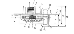
図1A、1B乃至図7A、7Bの実施の形態の駆動装置1は、例えばドアモジュールの機器支持体によって形成された支持要素4の平面部分40上に配置され、支持要素4の第1側に配置されたケーブル繰り出しハウジング2と、支持要素4の第1側とは反対の第2側に配置された駆動ハウジング7とを備えている。ケーブル繰り出しハウジング2はケーブルドラム3を支持要素4上に軸承する働きをし一方、駆動ハウジング7は特に駆動輪6を囲んでいる。この駆動輪は電動機ユニット8によって駆動可能であり、かつケーブルドラム3に連結されている。従って、駆動輪6を回転させることによってケーブルドラム3を駆動することができる。
The
支持要素4の第1側のケーブルドラム3は、所定の配置構造の場合には、例えば車両ドアの湿った空間内において車両ドアに配置されている。これに対して、駆動ハウジング7は車両ドアの乾燥した空間内にある。湿った空間と乾燥した空間の間の分離は支持要素4によって行われ、それにより駆動輪6とケーブルドラム3の間の交点は湿気を漏らさぬように封止可能であり、従って湿気は湿った空間から乾燥した空間内に達することができない。
In the case of a predetermined arrangement structure, the
ケーブル繰り出しハウジング2は底20と、この底20の中央から突出する、軸受心棒の形をした円筒状の軸受要素22と、この円筒状軸受要素22に対して平行に延在するハウジングウェブの形をしかつ軸受要素22から半径方向に離隔されたハウジング部分21とを備えている。軸受要素22にはケーブルドラム3が回転可能に軸承され、その際ケーブルドラム3は支持要素4上に保持されるようにケーブル繰り出しハウジング2によって囲まれている。
The
ケーブルドラム3は本体30を備え、この本体30の外周面には、引張りケーブル10を収容するためのケーブル用溝300が形成されている。ケーブルドラム3はその中空輪31が支持要素4の穴41に挿入され、駆動輪6に相対回転しないように連結されている。それによって、駆動輪6の回転運動はケーブルドラム3を回転運動させることになる。
The
駆動ハウジング7は封止要素5を介在して支持要素4の他の第2の側に装着され、ハウジングカップ70を備えている。このハウジングカップはその中央に形成されかつ円筒状の軸受心棒の形をした軸受要素72を備えている。この軸受要素は駆動輪6の穴62を貫通し、これにより駆動輪6を回転可能に軸承している。ハウジングカップ70にはウォームハウジング74が接続している。このウォームハウジング内には駆動ウォーム81が入れられている。この駆動ウォームは電動機ユニット8の電動機80の駆動軸800に連結され、そしてウォーム歯を介して駆動輪6の本体60の外歯600にかみ合っている。駆動軸800は電動機80とは反対側の端部で軸受82を介してウォームハウジング74内に軸承されている。この場合、電動機80は駆動ハウジング7の電動機カップ73内に入れられ、この電動機カップはハウジング蓋75によって外側が閉鎖されている。
The
駆動ハウジング7はさらに、電子機器ハウジング76を備えている。この電子機器ハウジング内にはプリント回路基板760が入れられ、このプリント回路基板はその上に配置された制御電子機器を備えている。電子機器ハウジング76は外側がハウジング板761によって閉鎖され、このハウジング板はその上に配置された、プリント回路基板760の電子機器を電気的に接続するための差込みコネクタ762を備えている。
The
駆動輪6は本体60から軸方向に突出する連結輪61を備え、この連結輪には外歯610が形成されている。この外歯はケーブルドラム3の中空輪31に係合し、それによって中空輪31の内歯310(例えば図1B参照)が連結輪61の外歯610にかみ合う。これにより、駆動輪6とケーブルドラム3が相対回転しないように互いに連結されるので、ケーブルドラム3は駆動輪6を駆動することによって支持要素4上で回転可能である。
The
駆動装置1を組み立てるために、一方ではケーブル繰り出しハウジング2が支持要素4に装着され、他方では駆動ハウジング7が支持要素4に装着される。支持要素4上での固定は、ねじ込み要素の形をした固定要素9を駆動ハウジング7の下側から係合穴721に挿入し、駆動ハウジング7の軸受要素72の穴720に通し、そして中央でケーブル繰り出しハウジング2の軸受要素22の穴221に係合させることによって行われる。ケーブル繰り出しハウジング2と駆動ハウジング7は固定要素9を介して軸受要素22、72のところで互いに軸方向に締付けられ、さらに支持要素4に固定される。
To assemble the
組立てのために、ケーブル繰り出しハウジング2が支持要素4の第1側に装着され、それによってケーブル繰り出しハウジング2はケーブルドラム3を取り囲み、支持要素4に保持される。この場合、ケーブル繰り出しハウジング2は軸受要素22に対して半径方向に離隔されたそのハウジング部分21の脚部210を介して、接触リング45に接触される。この接触リングは支持要素4の穴41を周方向に取り巻いている。接触リング45には、ウェブ状のピンの形をした、軸方向に突出するかみ合い連結要素42が形成されている。このかみ合い連結要素は、ケーブル繰り出しハウジング2を支持要素4に装着する際に、ハウジング部分21の脚部210のかみ合い連結穴212(図2参照)に係合し、それによってケーブル繰り出しハウジング2と支持要素4は軸受要素22によって定められた回転軸線D回りの相対回転が防止される。
For assembly, the
かみ合い連結要素42の内側には係止凹部420(例えば図3参照)が形成されている。この係止凹部には、ケーブル繰り出しハウジング2の装着時に、外側に突出したハウジング部分21の係止突起の形をした係止要素211が係合する。この係止連結部を介して、ケーブル繰り出しハウジング2はその中に入れられたケーブルドラム3と共に支持要素4上で予備組立て状態に保持される。この保持は、駆動ハウジング7が固定要素9を介してケーブル繰り出しハウジング2にまだ締付け固定されていないときにも行われる。従って、係止連結部は組立てを簡単にし、かつ駆動ハウジング7がまだ組立てられていないときにケーブル繰り出しハウジング2の落下を防止する。
A locking recess 420 (see, for example, FIG. 3) is formed inside the
ケーブルドラム3は予備組立て状態で、中空輪31の上縁部の半径方向に突出する載置要素32(例えば図1A参照)を介して、支持要素4の穴41内の載置リング46に載置される。それによって、ケーブルドラム3は予備組立て状態で、穴41を通って滑り抜けることができず、ケーブル繰り出しハウジング2を介して支持要素4に保持される。
In the pre-assembled state, the
載置要素32は特に、予備組立て状態での支持要素4上でのケーブルドラム3の位置保持のために役立つ。駆動装置1を完全に組立てた後で、ケーブルドラム3は中空輪31を介して駆動輪6に連結され、軸方向においてケーブル繰り出しハウジング2と駆動ハウジング7の間で固定される。
The mounting
ハウジング部分21の内面には、軸方向に延びていて半径方向内向きに突出する保持要素23が配置されている。この保持要素は本体30の外周面のケーブル用溝300の方に向き、好ましくは運転中にこの外周面に沿って滑動する。この保持要素23は、ケーブル用溝300に収容された引張りケーブル10がケーブル用溝300から飛び出さないようにする。
On the inner surface of the
駆動ハウジング7は、電動機カップ73が平面部分40の成形部44内に位置し、ウォームハウジング74が成形部44に接続する平面部分40の成形部440内に位置するように(図1A、1B、2参照)、支持要素4の第2の側に装着される。駆動ハウジング7の装着の際、係合ブッシュの形をした固定装置71の中に形成されたかみ合い連結穴710が支持要素4の下面から突出する、ピンの形をしたかみ合い連結要素43に係合する。固定装置71のかみ合い連結穴710が、支持要素4上のピンの形をしたかみ合い連結要素43と同様に、駆動ハウジング7の軸受要素72によって形成された回転軸線Dから半径方向に離隔されていることにより、駆動ハウジングがこのかみ合い連結係合によって支持要素4上に相対回転しないように固定されるので、駆動ハウジング7は回転防止される。
The
支持要素4のかみ合い連結要素43には、封止要素5のシール50の係合部分51が設けられている。従って、かみ合い連結要素43と固定装置71のかみ合い連結穴710とのかみ合い連結係合は、係合部分51を介在して行われる。これは音響的に分離する働きがある。
The
封止要素5には湾曲した部分52が形成されている。この部分はウォームハウジング74を収容するための成形部440の範囲に位置することになる。湾曲した部分52がウォームハウジング74と支持要素4の間の中間層を形成するので、支持要素4からの駆動ハウジング7の音響的な分離が達成される。
A
駆動ハウジング7が封止要素5を介在して支持要素4に装着されると、駆動ハウジング7が固定要素9を介してケーブル繰り出しハウジング2に締付けられるので、ケーブル繰り出しハウジング2と駆動ハウジング7が互いに固定されかつ支持要素4に固定される。図1A、1Bから判るように、固定要素9が駆動ハウジング7の軸受要素72内の係合穴721に挿入されるので、固定要素9はそのシャフト90が軸受要素72の頭部の穴720を通過し、ケーブル繰り出しハウジング2の軸受要素22の穴221に係合する。この場合、固定要素9の頭部91が軸受要素22とは反対の穴720の側に位置するので、固定要素9を軸受要素22の穴221にねじ込むことにより、ケーブル繰り出しハウジング2は駆動ハウジング7に対して締付けられる。この場合、ケーブル繰り出しハウジング2の軸受要素22と駆動ハウジング7の軸受要素72が、ケーブルドラム3のためと駆動輪6のための共通の回転軸線Dを形成するので、ケーブルドラム3と駆動輪6は運転中、互いに同軸におよび互いに一緒に回転することができる。
When the
図1A、1B乃至図7A、7Bの実施の形態の場合、電動機80の駆動軸800は駆動ハウジング7と相対的に軸の軸線W回りに回転可能に軸承されている。図4Bの断面図から判るように、電動機80は、多数のステータコイル830(図4Bには略示してある)を磁極歯に支持するステータ83と、多数の永久磁石極を有する磁石構造体840を支持するロータ84とによって形成されている。ロータ84はアウタロータであり、ステータ83の半径方向外側で回転する。ロータ84は駆動軸800に相対回転しないように連結されている。この駆動軸はブッシュ状の軸受要素85内でステータ83に対して回転可能に軸承されている。
In the embodiment of FIGS. 1A, 1B to 7A, 7B, the
電動機80はそのステータ83に、例えば6個、9個、12個、15個、18個、21個または24個の磁極歯を備え、この磁極歯はそれに配置されたステータコイル830を有する。電動機80の運転中、ステータコイル830は電子的に整流されて通電されるので、ステータ83で回転磁界が回転する。この回転磁界は(例えば4個、6個、8個、10個、12個、14個または16個の磁極を有する)磁石構造体840によってロータ84に発生する、トルクを生じるための励起磁界と協働し、それによってロータ84はステータ83回りに回転させられる。
The
図4Bの断面図から明らかなように、軸の軸線Wはケーブルドラム3と駆動輪6の回転軸線Dに対して斜めに延在している。これは支持要素4における電動機80の配置に付加的な自由度を生じる。これは駆動装置1をコンパクトな構造にする。
As is clear from the cross-sectional view of FIG. 4B, the axis W of the shaft extends diagonally with respect to the rotation axis D of the
これを図8〜10に基づいて説明する。 This will be described with reference to FIGS. 8-10.
図8は、軸の軸線Wが回転軸線Dに対して横方向に延在している従来の構造を示している。駆動ウォーム81が駆動輪6と同じ高さ位置に配置されているので、電動機カップ73内に入れられた電動機80は、支持要素4の第2側の構造空間を決定する比較的に大きな高さH1を、支持要素4の第2側に有することになる。電動機カップ73の高さH1は特に、電動機ハウジング76の高さHよりも大きい。(駆動ハウジング7とケーブル繰り出しハウジング2に沿って測定した)駆動装置1の全高はH3となる。この全高は電子機器ハウジング76とケーブル繰り出しハウジング2に沿って測定した高さH2よりも大きい。
FIG. 8 shows a conventional structure in which the axis W of the axis extends laterally with respect to the rotation axis D. Since the
図1A、1B乃至図7A、7Bの実施の形態に対応する図9の変形に示すように、軸の軸線Wが回転軸線Dに対して傾斜角をなして延在していると、電動機カップ73が支持要素4の第2側で電子機器ハウジング76から突出しないように、電動機80をケーブル繰り出しハウジング2の方へすらすことができる。従って、第2側における電動機カップ73の高さが電子機器ハウジング76の高さHに一致するので、電動機カップ73は(支持要素4に対して垂直方向に)付加的な構造スペースを必要としない。駆動装置1の全高H2は(専ら)ケーブル繰り出しハウジング2と電子器機器ハウジング76の高さによって決まる。
As shown in the deformation of FIG. 9 corresponding to the embodiment of FIGS. 1A, 1B to 7A, 7B, when the axis W of the shaft extends at an inclination angle with respect to the rotation axis D, the electric motor cup The
図9の変形の場合、電動機カップ73を入れた成形部44の上縁とケーブル繰り出しハウジング2の底20の上縁との間には、垂直方向に沿って(支持要素4に対して垂直に)間隔Aが存在する。従って、付加的な構造スペースが存在し、この構造スペースは、図10に示すように、電動機80の直径を拡大するために利用可能である。
In the case of the deformation of FIG. 9, between the upper edge of the molded
アウタロータとして形成されたロータ84によって決まる電動機80の直径は、成形部44の上縁が底20の上縁と同じ高さに位置するように拡大することができる。それによって、(支持要素4の第1側の成形部44の高さと支持要素4の第2側の電動機カップ73の高さHとによって決まる、)電動機80のために必要な構造スペースの全高は、ケーブル繰り出しハウジング2と電子機器ハウジング76の全高H2に一致する。この場合、ロータ直径84の増大により、電動機80と駆動軸800の(軸の軸線Wに沿って見た)軸方向長さを短縮することができるので、直径の増大は、トルクが同じである場合、電動機80の軸方向長さの短縮を可能にする。
The diameter of the
電動機80を取り囲む電動機カップ73は、支持要素4の成形部44内に入っている。成形部44が支持要素4の第1側のケーブル繰り出しハウジング2の空間内に延び、平面要素40から突出していることにより、電動機カップ73は、比喩的に言えば駆動ハウジング7に付設された支持要素4の第2側から観察すると、支持要素4内に沈下させることが可能である。これは、軸の軸線Wの傾斜した配向および電動機80の直径の拡大と共に、駆動装置1のきわめてコンパクトな構造を可能にする。
The
きわめて有利な実施の形態では、回転軸線Dに対する軸の軸線Wの傾斜位置は、図11に示すように、駆動ウォーム81のウォーム歯810のピッチ角度βが、回転軸線Dに対して横向きの横軸線Qと軸の軸線Wとがなす角度に一致するように選定可能である。これは、駆動輪6の外歯600を(回転軸線に対して平行に延びる歯先を有する)直歯として形成することを可能にする。これは、従来一般的であるはすばと比較して、駆動輪6の簡単で低コストの製作を可能にする。従って、軸の軸線Wの傾斜配置は構造スペースのために有利であるだけでなく同時に、駆動輪6の簡単で低コストの製作を可能にする。
In a very advantageous embodiment, the tilted position of the axis W of the axis with respect to the rotation axis D is such that the pitch angle β of the
図11から明らかなように、軸の軸線Wは回転軸線Dに対して角度αをなしている。角度βは90°−αの角度に相当する。 As is clear from FIG. 11, the axis W of the axis forms an angle α with respect to the rotation axis D. The angle β corresponds to an angle of 90 ° −α.
駆動ウォーム81は例えば駆動軸800と一体に形成することができる。しかし、付加的な別個の部品としての駆動ウォーム81を、駆動軸800に相対回転しないように配置することもできる。
The
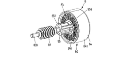
図13乃至21は、ハウジングカップ70内に入れられて軸受要素72に回転可能に軸承された駆動輪6を駆動するための電動機ユニット8の電動機80の実施の形態を示している。
13 to 21 show an embodiment of the
既に説明したように、電動機80はステータ83と、このステータ83の回りを回転する、アウタロータとして形成されたロータ84とを備えている。ロータ84は駆動軸800に連結され、この駆動軸には、駆動輪6を駆動するための駆動ウォーム81が配置されている。
As described above, the
図15A、15Bおよび17から明らかなように、ステータ83はステータ本体832を備えている。このステータ本体は例えば互いに装着された金属薄板によって積層薄板として形成され、多数の磁極歯831(実施の形態では9個の磁極歯831)を形成している。磁極歯831にはステータコイル830が設けられている。このステータコイルは図示した実施の形態の場合には同心的なコイルとして形成されている。この場合、各磁極歯831に1個または複数のコイルを配置することができ、このコイルはそれぞれ付設の磁極歯831の周りに巻かれた、それぞれ複数の巻きを有する巻線によって形成されている。
As is clear from FIGS. 15A, 15B and 17, the
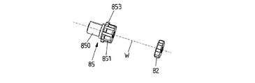
ステータ83は軸受要素85を介して駆動ハウジング7に固定連結されている。これは、軸受要素85の第1シャフト部分850が中央でステータ本体832に係合し、第1シャフト部分850に対して軸方向にずらした第2シャフト部分851がウォームハウジング74(例えば図4B参照)に差し込まれていることによって行われる。ステータ83は軸受要素85を介して駆動ハウジング7に固定連結されている。この場合、シャフト部分850、851は例えば圧着、接着、溶接またはその他の方法で、一方ではステータ本体832に、他方ではウォームハウジング74に固定されている。
The
軸受要素85は、例えば図16と図19A、19Bを合わせて見ることによって判るように、中央の軸受穴852を有する。この軸受穴に駆動軸800が通されて係合する。それによって、駆動軸800は軸受要素85内に回転可能に軸承されている。この場合、駆動軸800はステータ83とは反対側のその端部において、軸受要素82を介してウォームハウジング84内で支持されている(例えば図4B参照)。
The bearing
軸受要素85は例えば合成樹脂で製作可能であり、駆動軸800を軸承するために滑り特性を有すると有利である。
The bearing
アウタロータとして形成されたロータ84は磁極カップ841を備えている。この磁極カップは、図21に概略的に示すように、周方向に互いにずらした多数の磁極N、Sを有する磁石構造体840を備えている。磁石構造体840は例えば、磁化される(極性を与えられる)部分を交互に有する環状磁石として形成可能である。
The
図示した実施の形態の場合、磁石構造体840は、図21に示すように、互いに交互に配置された6個の磁極N、Sを有する。
In the illustrated embodiment, the
磁極カップ841は、例えば図16と図14Bから判るように、端壁842を介して、駆動ウォーム81とは反対側の駆動軸800の端部に連結されている。そのために、端壁842は連結フランジ843を備え、この連結フランジに駆動軸800が契合し、従って駆動軸800は連結フランジを介して磁極カップ841に相対回転しないように固定されている。
As can be seen from FIGS. 16 and 14B, for example, the
磁極カップ841はステータ83寄りの外周壁の内周面に、磁石構造体840を支持している。磁極カップ841は好ましくは強磁性特性を有する材料、例えば金属材料から作られ、磁石構造体840のための磁気的なループバックをなしていると有利である。
The
ロータ84が外側でステータ83の回りを回転し、それによって比較的に大きな半径でトルクが発生するので、電動機80は有利なトルク発生特性を有する。これは、駆動軸800と同様に電動機80の軸方向長さを短縮することを可能にし、ひいては軸方向における電動機ユニット8の構造スペースを縮小することを可能にする。
The
前述のように、電動機80はステータ83の異なる数の磁極歯831と、ロータ84の異なる数の磁極N、Sを有することができる。
As described above, the
図21に概略的に示すように、ステータコイル830は駆動装置1の運転中、ロータ83の磁極歯831で電子的に整流されて通電される。この場合、電子的な切換え器V1〜V6を介して、正の電位または負の電位が3つの位相線L1、L2、L3に交互に接続され、それによって回転する回転磁界がステータコイル830に発生する。この回転磁界はロータ84においてトルクを発生するために、ロータ84の磁石構造体840によって発生した励起磁界と協働する。この場合、ステータコイル830の接続は軸受要素85を介して行うことができる。この軸受要素を介して、例えば電子機器ハウジング76からステータコイル830まで導線を案内することができる。
As schematically shown in FIG. 21, the
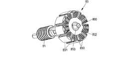
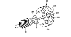
図22〜25は、図13〜21の実施の形態に対して少し変形された電動機ユニット8の実施の形態を示している。この実施の形態の場合、電動機80はアウタロータとして形成された、ステータ83の半径方向外側で回転するロータ84を備えている。ロータ84は磁極カップ841を備え、この磁極カップが駆動軸800に固定連結されているので、ロータ84を回転することにより、駆動軸800が回転させられ、そしてこの駆動軸800上に配置された駆動ウォーム81(この駆動ウォームは例えば駆動軸800と一体に形成されている)を介して駆動輪6を駆動する。
22 to 25 show an embodiment of the
図13〜21と図22〜25の実施の形態の場合、駆動軸800はそれぞれ2個の軸受要素82、85を介して、駆動ハウジング7に対して、すなわちウォームハウジング74に対して軸承されている。この場合、軸受要素82、85は軸の軸線W回りに駆動軸800を回転可能に軸承する。この軸の軸線Wはロータ84の回転軸線に一致する。
In the embodiments of FIGS. 13-21 and 22-25, the
軸受要素85は、図13〜21の実施の形態に基づいて上述したように、図22〜25の実施の形態の場合にも協働的な二重機能で、ステータ83をウォームハウジング74に対して固定し、かつ駆動軸800を軸承する働きをする。この場合、軸受要素85は好ましくは、ウォームハウジング74に係合するそのシャフト部分851に、他の第2軸受要素82と同じ外径を有する。それによって、内径がウォームハウジング74の長さに沿って一定の場合には、軸受要素82、85はウォームハウジング74内で同じような許容誤差を有する。
As described above based on the embodiment of FIGS. 13 to 21, the bearing
ステータ83を支持する第2軸受要素85は、互いに周方向にずらされた個々の突起によって形成されたストッパ853を備えている。ウォームハウジング74に係合する軸受要素85の場合、このストッパがウォームハウジング74の入口の段差部740に接触するので、ストッパ853を介して、ウォームハウジング74と相対的な軸受要素85の軸方向位置が固定される。
The
これに対して、第2の軸受要素82はウォームハウジング74内で段差部741に接触する。この段差部はウォームハウジング74の端部分742への移行部(駆動ウォーム81を収容するウォームハウジング74の部分よりも小さな内径を有する)に形成されている。それによって、第2の軸受要素82はウォームハウジング74内で軸方向に支持され、ウォームハウジング74内で所定の軸方向位置を占める。
On the other hand, the
駆動軸800は第2の軸受要素82に付設されたその端部のところで、ウォームハウジング74の端部分742内にある乗り上げ要素86を介して、ウォームハウジング74内で軸方向に支持されている。乗り上げ要素86は駆動ウォーム800のためのスラスト軸受を形成する。
The
これに対して、駆動軸800はその他端が、電動機カップ73に連結された駆動ハウジング7の蓋75に軸方向で支持されている。そのために、蓋75は駆動軸800の方へ突出する乗り上げ個所750を備えている。この乗り上げ個所は駆動軸800のために所定の軸方向乗り上げを生じる(特に図25参照)。それによって、駆動軸800の軸方向力が蓋75で受け止め可能であるので、駆動軸800の両側の軸方向支持によって、ウォームハウジング74とそれに接続する電動機カップ73内において駆動軸800のための実質的に遊びのない軸方向軸承が達成可能である。
On the other hand, the other end of the
蓋75は例えば電動機カップ73に溶接可能である。この場合、電動機カップ73に対して蓋75を締付けて溶接することできるので、組立て時に駆動ハウジング7内で駆動軸800の遊びを除去することができる。
The
本発明の根底をなす思想は、上述の実施の形態に限定されず、基本的には全く異なる態様で実施可能である。 The idea underlying the present invention is not limited to the above-described embodiment, and can be implemented in a completely different manner.
特に、上記種類の駆動装置は、窓ガラスでの使用に限定されず、車両内の他の調整要素、例えばスライドドア等を調整する働きをすることができる。 In particular, the above-mentioned type of drive device is not limited to use in window glass, and can function to adjust other adjustment elements in the vehicle, such as a sliding door.
駆動装置は特に(1個の)軸方向締付け固定要素を使用して簡単に組立て可能である。組立ては少ない組立てステップで行われ、この少ない組立てステップは、ケーブル繰り出しハウジングと駆動ハウジングを支持要素に確実な固定すると共に、簡単で望ましい。 The drive unit can be easily assembled, especially using (one) axial tightening fixing elements. Assembly is done in a small number of assembly steps, which are simple and desirable, as well as securely secure the cable feeding housing and drive housing to the support elements.
1 駆動装置
10 ケーブル
11 ガイドレール
110、111 方向変換部
12 伝動体
13 窓ガラス
2 ケーブル繰り出しハウジング
20 底
200、201 構造要素(補強リブ)
202 凹部(材料薄肉部)
21 ハウジング部分
210 脚部
211 係止要素
212 かみ合い連結穴(スリット穴)
22 軸受要素(軸受心棒)
220 センタリング円錐部
221 穴
23 保持要素
3 ケーブルドラム
30 本体
300 ケーブル線
31 中空輪
310 歯
32 載置要素
4 支持要素(機器支持体)
40 平面部分
41 穴
42 かみ合い連結要素
420 係止凹部
43 かみ合い連結要素
44 成形部
440 成形部
45 接触リング
46 載置リング
5 封止要素
50 シール
51 係合部分
52 湾曲した部分
6 駆動輪
60 本体
600 外歯
61 連結輪
610 歯
62 穴
7 駆動ハウジング
70 ハウジングカップ
71 固定装置(係合ブッシュ)
710 かみ合い連結穴
72 軸受要素(軸受心棒)
720 穴
721 係合穴
722 センタリング係合部
73 電動機カップ
74 ウォームハウジング
740、741 段差部
742 端部分
75 ハウジング蓋
750 乗り上げ個所
76 電子機器ハウジング
760 プリント回路基板
761 ハウジング板
762 差込みコネクタ
8 電動機ユニット
80 電動機
800 駆動軸
81 駆動ウォーム
810 ウォーム歯
82 軸受
820 ストッパ
83 ステータ
830 ステータコイル
831 磁極歯
832 ステータ本体
84 ロータ
840 磁石構造体(環状磁石)
841 磁極カップ
842 端壁
843 連結フランジ
85 軸受要素
850、851 シャフト部分
852 軸受穴
853 ストッパ
86 乗り上げ要素
9 固定要素
90 シャフト
91 頭部
α、β 角度
A 間隔
D 回転軸線
H、H1、H2 高さ
Q 横軸線
V1〜V6 電子的な切換え器
W 軸の軸線
1 Drive
202 Recess (thin part of material)
21
22 Bearing element (bearing mandrel)
220 Centering
40
710
720
841
Claims (15)
前記被覆要素を調整するための出力要素と、
ステータ(83)と、ロータ(84)と、前記ロータ(84)に連結されて軸の軸線(W)回りに回転可能である、前記出力要素を駆動するための駆動軸(800)とを有する電動機(80)を備えた電動機ユニット(8)と、
前記出力要素に作用連結され且つ前記駆動軸(800)に歯でかみ合っている駆動輪(6)と、
前記駆動輪(6)の歯(600)にかみ合うウォーム歯(810)を有する、前記駆動軸(800)に配置された駆動ウォーム(81)と、
前記電動機ユニット(8)を少なくとも部分的に囲んでおり、且つ、前記駆動ウォーム(81)が入れられているウォームハウジング(74)を備えている駆動ハウジング(7)とを具備し、
前記ステータ(83)が軸受要素(85)を介して、前記駆動ハウジング(7)の固定されたハウジング部分に連結され、前記軸受要素(85)が軸受穴(852)を有し、この軸受穴内に、前記駆動軸(800)が前記ステータ(83)と相対的に回転可能に軸承されている、上記駆動装置(1)において、
前記軸受要素(85)を前記ウォームハウジング(74)に圧入及び/又は前記ウォームハウジング(74)に接着又は溶接することにより、前記軸受要素(85)が前記ウォームハウジング(74)に係合し、且つ前記ウォームハウジング(74)に固定連結されていることを特徴とする駆動装置(1)。 A drive device (1) for adjusting a covering element of a vehicle, particularly a drive device for a window glass opening / closing adjustment device.
An output element for adjusting the covering element and
It has a stator (83), a rotor (84), and a drive shaft (800) for driving the output element, which is connected to the rotor (84) and is rotatable about the axis (W) of the shaft. An electric motor unit (8) equipped with an electric motor (80) and
A drive wheel (6) that is actuated and connected to the output element and meshes with the drive shaft (800) with teeth
A drive worm (81) arranged on the drive shaft (800) having worm teeth (810) that mesh with the teeth (600) of the drive wheel (6).
It comprises a drive housing (7) that at least partially surrounds the motor unit (8) and includes a worm housing (74) in which the drive worm (81) is housed .
The stator (83) is connected to a fixed housing portion of the drive housing (7) via a bearing element (85), and the bearing element (85) has a bearing hole (852) in the bearing hole. to the drive shaft (800) is journaled so as to be rotated relative to the stator (83), in the driving device (1),
By press-fitting the bearing element (85) into the worm housing (74) and / or adhering or welding the bearing element (74) to the worm housing (74), the bearing element (85) engages with the worm housing (74). A drive device (1) that is fixedly connected to the worm housing (74).
Applications Claiming Priority (3)
| Application Number | Priority Date | Filing Date | Title |
|---|---|---|---|
| DE102016216888.6A DE102016216888A1 (en) | 2016-09-06 | 2016-09-06 | Drive device for a window lift, with a bearing element for fixing a stator in a housing |
| DE102016216888.6 | 2016-09-06 | ||
| PCT/EP2017/072147 WO2018046459A1 (en) | 2016-09-06 | 2017-09-05 | Drive device for a window lift, having a bearing element for fixing a stator in a housing |
Publications (2)
| Publication Number | Publication Date |
|---|---|
| JP2019527032A JP2019527032A (en) | 2019-09-19 |
| JP6844004B2 true JP6844004B2 (en) | 2021-03-17 |
Family
ID=59811311
Family Applications (1)
| Application Number | Title | Priority Date | Filing Date |
|---|---|---|---|
| JP2019533679A Active JP6844004B2 (en) | 2016-09-06 | 2017-09-05 | Drive device for window glass open / close adjustment device with bearing elements for fixing the stator in the housing |
Country Status (7)
| Country | Link |
|---|---|
| US (1) | US11828098B2 (en) |
| EP (1) | EP3510694B1 (en) |
| JP (1) | JP6844004B2 (en) |
| CN (1) | CN109863674B (en) |
| DE (1) | DE102016216888A1 (en) |
| MA (1) | MA46388A (en) |
| WO (1) | WO2018046459A1 (en) |
Families Citing this family (10)
| Publication number | Priority date | Publication date | Assignee | Title |
|---|---|---|---|---|
| DE102016216877A1 (en) * | 2016-09-06 | 2018-03-08 | Brose Fahrzeugteile Gmbh & Co. Kommanditgesellschaft, Bamberg | Drive device for a window lift, with a stop ring for a cable drum |
| DE102019203525A1 (en) | 2019-03-15 | 2020-09-17 | Brose Fahrzeugteile SE & Co. Kommanditgesellschaft, Würzburg | Drive device with a brushless electric motor |
| JP7413950B2 (en) * | 2020-08-19 | 2024-01-16 | トヨタ紡織株式会社 | gear device |
| DE102021205499A1 (en) | 2021-03-24 | 2022-09-29 | Brose Fahrzeugteile Se & Co. Kommanditgesellschaft, Bamberg | Drive device and stator assembly therefor |
| WO2022200313A1 (en) | 2021-03-24 | 2022-09-29 | Brose Fahrzeugteile Se & Co. Kommanditgesellschaft, Bamberg | Drive device and stator assembly therefor |
| DE102021209020A1 (en) | 2021-08-17 | 2023-02-23 | Brose Fahrzeugteile Se & Co. Kommanditgesellschaft, Bamberg | Drive device, in particular adjusting drive of a motor vehicle |
| DE102021212840A1 (en) | 2021-11-16 | 2023-05-17 | Brose Fahrzeugteile Se & Co. Kommanditgesellschaft, Bamberg | Driving device with a brushless electric motor |
| DE102021212839A1 (en) | 2021-11-16 | 2023-05-17 | Brose Fahrzeugteile Se & Co. Kommanditgesellschaft, Bamberg | Driving device with a brushless electric motor |
| DE102023201068A1 (en) | 2023-02-09 | 2024-08-14 | Brose Fahrzeugteile Se & Co. Kommanditgesellschaft, Bamberg | Drive device with a brushless electric motor |
| DE102023201069A1 (en) | 2023-02-09 | 2024-08-14 | Brose Fahrzeugteile Se & Co. Kommanditgesellschaft, Bamberg | Stator assembly for an electric motor and drive device |
Family Cites Families (25)
| Publication number | Priority date | Publication date | Assignee | Title |
|---|---|---|---|---|
| US2848218A (en) * | 1953-11-24 | 1958-08-19 | Gen Motors Corp | Window regulator |
| US3455174A (en) | 1967-04-11 | 1969-07-15 | Ferro Mfg Corp | Window regulator motor and transmission housing |
| FR2050946A5 (en) | 1969-06-30 | 1971-04-02 | Espanola Magnetos Fab | |
| JPS5523711A (en) | 1978-07-29 | 1980-02-20 | Sony Corp | Rotary electric machine |
| SU1083902A3 (en) | 1979-12-27 | 1984-03-30 | Металлверк Макс Брозе Гмбх Унд Ко (Фирма) | Electrical drive of automobile vehicle window raiser |
| DE9209929U1 (en) | 1992-07-23 | 1992-09-24 | Siemens AG, 8000 München | Window regulator drive unit |
| DE29702525U1 (en) * | 1997-02-14 | 1998-06-10 | Robert Bosch Gmbh, 70469 Stuttgart | Device for adjusting components belonging to a motor vehicle |
| DE19733566B4 (en) * | 1997-08-02 | 2005-10-13 | Minebea Co., Ltd. | Spindle motor with sleeve |
| JP3924858B2 (en) * | 1997-09-02 | 2007-06-06 | 株式会社明電舎 | Home elevator lifting drive |
| DE19926171A1 (en) * | 1999-06-09 | 2000-12-14 | Bosch Gmbh Robert | Electric motor |
| DE10310186A1 (en) | 2003-03-08 | 2004-09-16 | Valeo Wischersysteme Gmbh | Bearing for vehicle windscreen wiper motor shaft, has axially- and radially-supporting components made of plastic and connected by welding |
| DE102004044863A1 (en) | 2004-09-14 | 2006-03-30 | Brose Fahrzeugteile Gmbh & Co. Kg, Coburg | Drive unit for cable-type electric window lifter for motor vehicle, has reinforcing insert provided in axial cavity of plastics shaft |
| US7019423B1 (en) * | 2005-02-10 | 2006-03-28 | Sunonwealth Electric Machine Industry Co., Ltd. | Brushless DC motor with tray coupling structure |
| DE102005028815A1 (en) | 2005-06-22 | 2007-01-04 | Robert Bosch Gmbh | Transmission drive unit with symmetrically arranged connection plug |
| DE102006047883B3 (en) | 2006-05-06 | 2007-10-18 | Hans Hermann Rottmerhusen | Electric motor e.g. external rotor alternating-current motor, for e.g. thicknessing machine, has shaft gripped in gear housing, where distance from shaft of rotor to air gap of motor is larger in relation to outside diameter of motor |
| DE112008002124B4 (en) | 2007-08-06 | 2022-01-20 | Delphi Technologies, Inc. | Linear drive actuator for a moveable vehicle panel |
| JP2009044818A (en) * | 2007-08-07 | 2009-02-26 | Nippon Densan Corp | Motor and servo unit mounted with the motor |
| JP5203892B2 (en) * | 2008-02-06 | 2013-06-05 | アスモ株式会社 | Rotating shaft assembly method and rotating shaft bearing structure |
| DE102008043173A1 (en) * | 2008-07-04 | 2010-01-07 | Robert Bosch Gmbh | Transmission drive unit with a self-locking device |
| JP2010093943A (en) * | 2008-10-08 | 2010-04-22 | Nsk Ltd | Electric motor with gear mechanism, and motor-driven power steering device using the same |
| DE202010002222U1 (en) * | 2010-02-04 | 2011-06-09 | Brose Fahrzeugteile GmbH & Co. Kommanditgesellschaft, Hallstadt, 96103 | Door module with an acoustic decoupling agent |
| DE102010013597B3 (en) * | 2010-03-31 | 2011-06-01 | Brose Fahrzeugteile Gmbh & Co. Kommanditgesellschaft, Hallstadt | Method for controlling a drive system of an actuating element of a motor vehicle and corresponding drive system |
| DE102011005360A1 (en) | 2011-03-10 | 2012-09-13 | Brose Fahrzeugteile Gmbh & Co. Kg, Hallstadt | Drive device with actively mounted drive shaft |
| WO2013175624A1 (en) * | 2012-05-25 | 2013-11-28 | 株式会社ミツバ | Electric motor |
| DE102013204436A1 (en) | 2013-03-14 | 2014-09-18 | Krones Ag | Drive for a transport device, set of drives and method for driving a transport device |
-
2016
- 2016-09-06 DE DE102016216888.6A patent/DE102016216888A1/en not_active Withdrawn
-
2017
- 2017-09-05 WO PCT/EP2017/072147 patent/WO2018046459A1/en unknown
- 2017-09-05 MA MA046388A patent/MA46388A/en unknown
- 2017-09-05 US US16/331,023 patent/US11828098B2/en active Active
- 2017-09-05 JP JP2019533679A patent/JP6844004B2/en active Active
- 2017-09-05 EP EP17764369.9A patent/EP3510694B1/en active Active
- 2017-09-05 CN CN201780064540.8A patent/CN109863674B/en active Active
Also Published As
| Publication number | Publication date |
|---|---|
| JP2019527032A (en) | 2019-09-19 |
| DE102016216888A1 (en) | 2018-03-08 |
| WO2018046459A1 (en) | 2018-03-15 |
| MA46388A (en) | 2019-07-17 |
| EP3510694A1 (en) | 2019-07-17 |
| US11828098B2 (en) | 2023-11-28 |
| CN109863674A (en) | 2019-06-07 |
| EP3510694B1 (en) | 2020-11-11 |
| US20190277079A1 (en) | 2019-09-12 |
| CN109863674B (en) | 2021-12-21 |
Similar Documents
| Publication | Publication Date | Title |
|---|---|---|
| JP6844004B2 (en) | Drive device for window glass open / close adjustment device with bearing elements for fixing the stator in the housing | |
| JP2019527031A (en) | Driving device for window glass opening / closing adjustment device provided with outer rotor motor | |
| JP6505801B2 (en) | Lift device for vehicle rear door and drive device therefor | |
| JP6410907B2 (en) | Motor equipment | |
| KR20220056819A (en) | Actuator | |
| US20210159758A1 (en) | Motor with speed reducer, and rear wiper motor | |
| CN103373383A (en) | Electric cart and gear motor component thereof | |
| JP2015220995A (en) | Power strut | |
| US20070024148A1 (en) | Electric motor | |
| JP3985815B2 (en) | Electric actuator | |
| JP2019529843A (en) | Driving device for window glass opening / closing adjustment device having axis of axis extending obliquely | |
| US20220316560A1 (en) | Rotation driving device | |
| JP5138489B2 (en) | Resolver rotor fixing structure and brushless motor | |
| US8796891B2 (en) | Brushless DC motor | |
| WO2015115368A1 (en) | Motor unit, motor with speed reduction mechanism, and sliding door automatic opening/closing device | |
| US20070159013A1 (en) | Motor drive device | |
| JP4848305B2 (en) | motor | |
| JP2005224077A (en) | Motor-driving device | |
| JP4549225B2 (en) | Actuator motor | |
| JP2007244084A (en) | Rotary electric machine | |
| JP2003164113A (en) | Rotation detector for small-sized motor equipped with worm reducer | |
| US10320264B2 (en) | Brushless motor | |
| JP4823173B2 (en) | Brush holder | |
| JP2007215308A (en) | Motor driving device | |
| KR102157024B1 (en) | Actuator module using the BLDC motor |
Legal Events
| Date | Code | Title | Description |
|---|---|---|---|
| A621 | Written request for application examination |
Free format text: JAPANESE INTERMEDIATE CODE: A621 Effective date: 20190424 |
|
| A521 | Request for written amendment filed |
Free format text: JAPANESE INTERMEDIATE CODE: A523 Effective date: 20190829 |
|
| A131 | Notification of reasons for refusal |
Free format text: JAPANESE INTERMEDIATE CODE: A131 Effective date: 20200526 |
|
| A521 | Request for written amendment filed |
Free format text: JAPANESE INTERMEDIATE CODE: A523 Effective date: 20200824 |
|
| TRDD | Decision of grant or rejection written | ||
| A01 | Written decision to grant a patent or to grant a registration (utility model) |
Free format text: JAPANESE INTERMEDIATE CODE: A01 Effective date: 20210202 |
|
| A61 | First payment of annual fees (during grant procedure) |
Free format text: JAPANESE INTERMEDIATE CODE: A61 Effective date: 20210224 |
|
| R150 | Certificate of patent or registration of utility model |
Ref document number: 6844004 Country of ref document: JP Free format text: JAPANESE INTERMEDIATE CODE: R150 |
|
| S111 | Request for change of ownership or part of ownership |
Free format text: JAPANESE INTERMEDIATE CODE: R313113 |
|
| R350 | Written notification of registration of transfer |
Free format text: JAPANESE INTERMEDIATE CODE: R350 |
|
| R250 | Receipt of annual fees |
Free format text: JAPANESE INTERMEDIATE CODE: R250 |