JP6835633B2 - Steering handle structure - Google Patents
Steering handle structure Download PDFInfo
- Publication number
- JP6835633B2 JP6835633B2 JP2017045625A JP2017045625A JP6835633B2 JP 6835633 B2 JP6835633 B2 JP 6835633B2 JP 2017045625 A JP2017045625 A JP 2017045625A JP 2017045625 A JP2017045625 A JP 2017045625A JP 6835633 B2 JP6835633 B2 JP 6835633B2
- Authority
- JP
- Japan
- Prior art keywords
- guide member
- lock spring
- steering handle
- hook portion
- main body
- Prior art date
- Legal status (The legal status is an assumption and is not a legal conclusion. Google has not performed a legal analysis and makes no representation as to the accuracy of the status listed.)
- Active
Links
Images


Classifications
-
- B—PERFORMING OPERATIONS; TRANSPORTING
- B62—LAND VEHICLES FOR TRAVELLING OTHERWISE THAN ON RAILS
- B62D—MOTOR VEHICLES; TRAILERS
- B62D7/00—Steering linkage; Stub axles or their mountings
- B62D7/22—Arrangements for reducing or eliminating reaction, e.g. vibration, from parts, e.g. wheels, of the steering system
- B62D7/222—Arrangements for reducing or eliminating reaction, e.g. vibration, from parts, e.g. wheels, of the steering system acting on the steering wheel
-
- B—PERFORMING OPERATIONS; TRANSPORTING
- B60—VEHICLES IN GENERAL
- B60R—VEHICLES, VEHICLE FITTINGS, OR VEHICLE PARTS, NOT OTHERWISE PROVIDED FOR
- B60R21/00—Arrangements or fittings on vehicles for protecting or preventing injuries to occupants or pedestrians in case of accidents or other traffic risks
- B60R21/02—Occupant safety arrangements or fittings, e.g. crash pads
- B60R21/16—Inflatable occupant restraints or confinements designed to inflate upon impact or impending impact, e.g. air bags
- B60R21/20—Arrangements for storing inflatable members in their non-use or deflated condition; Arrangement or mounting of air bag modules or components
- B60R21/203—Arrangements for storing inflatable members in their non-use or deflated condition; Arrangement or mounting of air bag modules or components in steering wheels or steering columns
- B60R21/2035—Arrangements for storing inflatable members in their non-use or deflated condition; Arrangement or mounting of air bag modules or components in steering wheels or steering columns using modules containing inflator, bag and cover attachable to the steering wheel as a complete sub-unit
- B60R21/2037—Arrangements for storing inflatable members in their non-use or deflated condition; Arrangement or mounting of air bag modules or components in steering wheels or steering columns using modules containing inflator, bag and cover attachable to the steering wheel as a complete sub-unit the module or a major component thereof being yieldably mounted, e.g. for actuating the horn switch or for protecting the driver in a non-deployment situation
-
- B—PERFORMING OPERATIONS; TRANSPORTING
- B62—LAND VEHICLES FOR TRAVELLING OTHERWISE THAN ON RAILS
- B62D—MOTOR VEHICLES; TRAILERS
- B62D1/00—Steering controls, i.e. means for initiating a change of direction of the vehicle
- B62D1/02—Steering controls, i.e. means for initiating a change of direction of the vehicle vehicle-mounted
- B62D1/04—Hand wheels
-
- B—PERFORMING OPERATIONS; TRANSPORTING
- B60—VEHICLES IN GENERAL
- B60Y—INDEXING SCHEME RELATING TO ASPECTS CROSS-CUTTING VEHICLE TECHNOLOGY
- B60Y2410/00—Constructional features of vehicle sub-units
- B60Y2410/113—Mount clips, snap-fit, e.g. quick fit with elastic members
Landscapes
- Engineering & Computer Science (AREA)
- Mechanical Engineering (AREA)
- Chemical & Material Sciences (AREA)
- Combustion & Propulsion (AREA)
- Transportation (AREA)
- Air Bags (AREA)
- Steering Controls (AREA)
- Vibration Prevention Devices (AREA)
Description
本発明は、ステアリングハンドル構造に関するものである。 The present invention relates to a steering handle structure.
運転席用エアバッグは、ステアリングハンドル(のボス部)に対してエアバッグモジュールを取付けた構造が一般的である。エアバッグモジュールをステアリングハンドルに取付けるに際しては、スナップイン方式で簡単に行えるようにすることが望まれる。また、質量体としてのエアバッグモジュールを、ステアリングハンドルに対して弾力的に取付けることにより、走行中のステアリングハンドルの振動を低減するダイナミックダンパ機能を得ることも行われている。 The driver's seat airbag generally has a structure in which an airbag module is attached to (the boss portion of) the steering handle. When attaching the airbag module to the steering wheel, it is desirable to make it easy to use the snap-in method. Further, by elastically attaching the airbag module as a mass body to the steering handle, a dynamic damper function for reducing vibration of the steering handle during traveling is also obtained.
特許文献1、特許文献2には、ダイナミックダンパ機能を得つつ、スナップイン方式でエアバッグモジュールをステアリングハンドルに取付けるものが開示されている。
前述した各特許文献に記載のものでは、ダイナミックダンパ機能を得つつスナップイン方式でエアバッグモジュールをステアリングハンドルに取付けるための機構が相当に複雑で必要な部品点数も多くなり、この点において対策が望まれるものである。 In the above-mentioned patent documents, the mechanism for attaching the airbag module to the steering handle by the snap-in method while obtaining the dynamic damper function is considerably complicated, and the number of required parts is increased. It is what is desired.
本発明は以上のような事情を勘案してなされたもので、その目的は、ダイナミックダンパ機能を得つつスナップイン方式でエアバッグモジュールをステアリングハンドルに取付け可能とする場合に、部品点数が少なくて簡単な構造ですむようにしたステアリングハンドル構造を提供することにある。 The present invention has been made in consideration of the above circumstances, and an object of the present invention is to reduce the number of parts when the airbag module can be attached to the steering handle by the snap-in method while obtaining the dynamic damper function. The purpose is to provide a steering wheel structure that requires a simple structure.
前記目的を達成するため、本発明にあっては次のような第1の解決手法を採択してある。すなわち、請求項1に記載のように、
ステアリングハンドルに形成されたフック部を、エアバッグモジュールの取付板部に形成された取付孔に挿入することにより、該エアバッグモジュールの該ステアリングハンドルに対する取付けを行うようにしたステアリングハンドル構造であって、
前記フック部が挿入される筒状のガイド部材が、環状のダンパーゴム内に前記ステアリングハンドル側から挿通可能とされて前記取付孔に嵌合、保持された本体部と、前記本体部の一端部側において形成されて前記取付孔のうち前記ステアリングハンドル側の縁部に係止されるフランジ部と、を有し、
前記本体部に、前記ガイド部材に挿入された前記フック部を係止して、該フック部の抜けを規制するロックばねが保持され、
前記ロックばねによって前記フック部を係止している状態において、該ロックばねと前記取付板部との間に、該フック部の断面方向において隙間が形成されている、
ようにしてある。
In order to achieve the above object, the following first solution method is adopted in the present invention. That is, as described in
The steering handle structure is such that the airbag module is attached to the steering handle by inserting the hook portion formed in the steering handle into the mounting hole formed in the mounting plate portion of the airbag module. ,
A tubular guide member into which the hook portion is inserted is made to be able to be inserted into the annular damper rubber from the steering handle side, and is fitted and held in the mounting hole, and one end portion of the main body portion. It has a flange portion formed on the side and locked to the edge portion on the steering wheel side of the mounting holes.
A lock spring that locks the hook portion inserted into the guide member and restricts the hook portion from coming off is held in the main body portion .
In a state where the hook portion is locked by the lock spring, a gap is formed between the lock spring and the mounting plate portion in the cross-sectional direction of the hook portion.
I am doing it.
上記第1の解決手法によれば、フック部をガイド部材に挿入することにより、フック部がロックばねにより係止されてその抜け止めが行われる。つまり、エアバッグモジュールを、スナップイン方式で簡単にステアリングハンドルに取付けることができる。また、走行中は、ダンパーゴムの弾性と質量体としてのエアバッグモジュールとによるダイナミックダンパ機能によって、ステアリングハンドルの振動を低減することができる。そして、ダイナミックダンパ機能を得つつスナップイン方式での取付けを行うために必要な部品点数も少なくてすみ、構造も極めて簡単なものとすることができる。また、ガイド部材をロックばねの保持部材として兼用させて、構造の簡単化等の上でさらに好ましいものとなる。 According to the first solution method, by inserting the hook portion into the guide member, the hook portion is locked by the lock spring and the hook portion is prevented from coming off. That is, the airbag module can be easily attached to the steering wheel by the snap-in method. Further, during traveling, the vibration of the steering handle can be reduced by the elasticity of the damper rubber and the dynamic damper function by the airbag module as a mass body. Further, the number of parts required for mounting by the snap-in method while obtaining the dynamic damper function can be reduced, and the structure can be made extremely simple. Further, the guide member is also used as a holding member for the lock spring, which is more preferable in terms of simplification of the structure and the like.
以上に加えて、前記ロックばねによって前記フック部を係止している状態において、該ロックばねと前記取付板部との間に、該フック部の断面方向において隙間が形成されていることから、ステアリングハンドルからの振動がフック部からロックばねを介してエアバッグモジュール側に伝達されてしまう事態を防止して、ダイナミックダンパ機能を確実に得る上で好ましいものとなる。 In addition to the above, in a state where the hook portion is locked by the lock spring, a gap is formed between the lock spring and the mounting plate portion in the cross-sectional direction of the hook portion . vibration from the scan tearing handle to prevent the result being transmitted to the air bag module side via the lock spring from the hook portion, which is preferable for obtaining reliably the dynamic damper function.
上記第1の解決手法を前提とした好ましい態様は、次のとおりである。すなわち、
前記ロックばねは、前記取付板部を挟んで前記フランジ部とは反対側の位置において前記本体部に保持されており、
前記ガイド部材は、前記フランジ部と前記ロックばねとによって、前記取付孔の軸線方向に移動して前記本体部が該取付孔から抜けることが規制されている、
ようにしてある(請求項2対応)。この場合、ロックばねを有効に利用して、つまり別途固定具等の別部材を用いることなく、ガイド部材を所定位置に取付けておくことができる。
A preferred embodiment premised on the first solution method is as follows. That is,
The lock spring is held by the main body portion at a position opposite to the flange portion across the mounting plate portion.
The guide member is regulated by the flange portion and the lock spring so as to move in the axial direction of the mounting hole and the main body portion to come out of the mounting hole.
(Corresponding to claim 2). In this case, the guide member can be attached at a predetermined position by effectively using the lock spring, that is, without using a separate member such as a fixture.
前記ロックばねは、略U字状に形成されることにより対向して伸びる一対の棒状部と、該一対の棒状部の一端部同士を連結する連結部と、を有し、
前記ロックばねは、前記一対の棒状部のうち少なくとも一方の棒状部が前記ガイド部材内を横断するようにして該ガイド部材に保持され、
前記ガイド部材に挿入された前記フック部が、前記一対の棒状部の間隔を拡大方向に弾性変形させつつ該一対の棒状部を乗り越えて、該一対の棒状部を乗り越えた後に該一対の棒状部がその間隔が狭くなるように弾性復帰することにより、該フック部の該ロックばねからの抜けが規制されるように設定されている、
ようにしてある(請求項3対応)。この場合、弾性変形によって間隔が変化される一対の棒状部を利用して、フック部を容易に係止させつつ確実な係止状態を確保することができる。
また、前記本体部の両側面にはそれぞれ保持孔が形成され、
前記一対の棒状部の一方が前記保持孔の一方に嵌合されると共に、該一対の棒状部の他方が該保持孔の他方に嵌合されている、ようにすることができる(請求項4対応)。
The lock spring has a pair of rod-shaped portions that are formed in a substantially U shape and extend so as to face each other, and a connecting portion that connects one ends of the pair of rod-shaped portions.
The lock spring is held by the guide member so that at least one of the pair of rod-shaped portions traverses the guide member.
The hook portion inserted into the guide member overcomes the pair of rod-shaped portions while elastically deforming the distance between the pair of rod-shaped portions in the expanding direction, and after overcoming the pair of rod-shaped portions, the pair of rod-shaped portions. Is set so that the hook portion is restricted from coming off from the lock spring by elastically returning so that the interval is narrowed.
(Corresponding to claim 3). In this case, a pair of rod-shaped portions whose intervals are changed by elastic deformation can be used to easily lock the hook portions while ensuring a reliable locking state.
In addition, holding holes are formed on both side surfaces of the main body.
One of the pair of rod-shaped portions may be fitted to one of the holding holes, and the other of the pair of rod-shaped portions may be fitted to the other of the holding holes (claim 4). Correspondence).
前記フック部の側面のうち前記ロックばねに対面する少なくとも1つの面が、平坦面に形成されている、ようにしてある(請求項5対応)。この場合、ロックばねとフック部との間での回り止めを行いつつ、フック部を確実に係止しておく上で好ましいものとなる。 At least one surface of the side surface of the hook portion facing the lock spring is formed as a flat surface (corresponding to claim 5). In this case, it is preferable to securely lock the hook portion while stopping the rotation between the lock spring and the hook portion.
前記ガイド部材の端部によって、前記ロックばねによって係止されている状態における前記フック部の先端部が覆われている、ようにしてある(請求項6対応)。この場合、ガイド部材を有効に利用して、膨張、展開されるエアバッグがフック部の先端部に接触してしまう事態を防止することができる。 The end portion of the guide member covers the tip end portion of the hook portion in a state of being locked by the lock spring (corresponding to claim 6). In this case, the guide member can be effectively used to prevent the inflated and deployed airbag from coming into contact with the tip of the hook portion.
前記ダンパーゴムの外周に、該ダンパーゴムが拡径する方向への弾性変形を規制するスペーサが嵌合されている、ようにしてある(請求項7対応)。この場合、ダンパーゴムが過剰に震動することを制限して、ダンパーゴムが不必要に拡径変形したり変動することを防止して、ダイナミックダンパ機能を確実に得る上で好ましいものとなる。 A spacer that regulates elastic deformation in the direction in which the damper rubber expands in diameter is fitted on the outer circumference of the damper rubber (corresponding to claim 7). In this case, it is preferable to limit the excessive vibration of the damper rubber, prevent the damper rubber from being unnecessarily expanded and deformed or fluctuate, and to surely obtain the dynamic damper function.
前記エアバッグモジュールは、前記フック部が前記ロックばねによって係止されている状態で、該フック部の長手方向に所定範囲内で変位可能とされ、
リターンスプリングにより、前記エアバッグモジュールが前記ステアリングハンドルから離間する方向に付勢されている、
ようにしてある(請求項8対応)。この場合、エアバッグモジュールが押圧操作されたときにホーンを作動させる構成とする上で好ましいものとなる。
The airbag module can be displaced within a predetermined range in the longitudinal direction of the hook portion in a state where the hook portion is locked by the lock spring.
The return spring urges the airbag module in a direction away from the steering handle.
(Corresponding to claim 8). In this case, it is preferable to configure the horn to operate when the airbag module is pressed.
前記目的を達成するため、本発明にあっては次のような第2の解決手法を採択してある。すなわち、請求項9に記載のように、
ステアリングハンドルに形成されたフック部を、エアバッグモジュールの取付板部に形成された取付孔に挿入することにより、該エアバッグモジュールの該ステアリングハンドルに対する取付けを行うようにしたステアリングハンドル構造であって、
前記フック部が挿入される筒状のガイド部材が、環状のダンパーゴムを介して前記取付孔に嵌合、保持され、
前記ガイド部材に、前記ガイド部材に挿入された前記フック部を係止して、該フック部の抜けを規制するロックばねが保持され、
前記ガイド部材は、前記ダンパーゴム内に前記ステアリングハンドル側から挿通可能な本体部と、該本体部の一端部側に形成され、前記取付孔のうち前記ステアリングハンドル側の縁部に係止されるフランジ部と、を有し、
前記ロックばねは、前記取付板部を挟んで前記フランジ部とは反対側の位置において前記本体部に保持されており、
前記ガイド部材は、前記フランジ部と前記ロックばねとによって、前記取付孔の軸線方向に移動して前記本体部が該取付孔から抜けることが規制され、
前記本体部の外周面に前記ダンパーゴムの内周面に当接する凸部が形成されて、該ガイド部材と該ダンパーゴムとの間には該凸部の周囲において隙間が形成されている、
ようにしてある。
上記第2の解決手法によれば、フック部をガイド部材に挿入することにより、フック部がロックばねにより係止されてその抜け止めが行われる。つまり、エアバッグモジュールを、スナップイン方式で簡単にステアリングハンドルに取付けることができる。また、走行中は、ダンパーゴムの弾性と質量体としてのエアバッグモジュールとによるダイナミックダンパ機能によって、ステアリングハンドルの振動を低減することができる。そして、ダイナミックダンパ機能を得つつスナップイン方式での取付けを行うために必要な部品点数も少なくてすみ、構造も極めて簡単なものとすることができる。また、ガイド部材をロックばねの保持部材として兼用させて、構造の簡単化等の上でさらに好ましいものとなる。また、ロックばねを有効に利用して、つまり別途固定具等の別部材を用いることなく、ガイド部材を所定位置に取付けておくことができる。さらに、ガイド部材の位置決めをダンパーゴムを利用してより確実に行えるようにしつつ、ダンパーゴムの可動域を拡大してダイナミックダンパ性能を向上させる上で好ましいものとなる。
In order to achieve the above object, the following second solution method is adopted in the present invention. That is, as described in claim 9.
The steering handle structure is such that the airbag module is attached to the steering handle by inserting the hook portion formed in the steering handle into the mounting hole formed in the mounting plate portion of the airbag module. ,
A tubular guide member into which the hook portion is inserted is fitted and held in the mounting hole via an annular damper rubber.
A lock spring that locks the hook portion inserted into the guide member to the guide member and restricts the hook portion from coming off is held.
The guide member is formed in the damper rubber with a main body portion that can be inserted from the steering handle side and one end side of the main body portion, and is locked to the edge portion of the mounting hole on the steering handle side. With a flange part,
The lock spring is held by the main body portion at a position opposite to the flange portion across the mounting plate portion.
The guide member is restricted from moving in the axial direction of the mounting hole by the flange portion and the lock spring so that the main body portion comes out of the mounting hole.
A convex portion that abuts on the inner peripheral surface of the damper rubber is formed on the outer peripheral surface of the main body portion, and a gap is formed around the convex portion between the guide member and the damper rubber.
I am doing it.
According to the second solution method, by inserting the hook portion into the guide member, the hook portion is locked by the lock spring and the hook portion is prevented from coming off. That is, the airbag module can be easily attached to the steering wheel by the snap-in method. Further, during traveling, the vibration of the steering handle can be reduced by the elasticity of the damper rubber and the dynamic damper function by the airbag module as a mass body. Further, the number of parts required for mounting by the snap-in method while obtaining the dynamic damper function can be reduced, and the structure can be made extremely simple. Further, the guide member is also used as a holding member for the lock spring, which is more preferable in terms of simplification of the structure and the like. Further, the guide member can be attached at a predetermined position by effectively using the lock spring, that is, without using a separate member such as a fixture. Further, it is preferable to expand the range of motion of the damper rubber and improve the dynamic damper performance while making the positioning of the guide member more reliable by using the damper rubber.
上記第1の解決手法または第2の解決手法を前提として、次のような態様を採択することができる。すなわち、
前記フランジ部と該フランジ部に対向する前記ダンパーゴムとの間に隙間が形成されている、ようにしてある(請求項10対応)。この場合、ダンパーゴムの可動域を拡大してダイナミックダンパ性能を向上させる上で好ましいものとなる。
On the premise of the first solution method or the second solution method, the following aspects can be adopted. That is,
A gap is formed between the flange portion and the damper rubber facing the flange portion (corresponding to claim 10). In this case, it is preferable to expand the range of motion of the damper rubber and improve the dynamic damper performance.
本発明によれば、部品点数が少なくて簡単な構造でもって、ダイナミックダンパ機能を得つつスナップイン方式でエアバッグモジュールをステアリングハンドルに取付けることが可能となる。 According to the present invention, it is possible to attach the airbag module to the steering handle by a snap-in method while obtaining a dynamic damper function with a simple structure with a small number of parts.
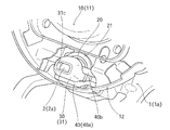
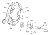
図1において、1はステアリングハンドルの芯金であり、そのボス部1aに対して、エアバッグモジュール10が後述のようにして取付けられる。
In FIG. 1,
図3に示すように、上記ボス部1aには、複数(実施形態では3個)のフック部2が、後方(ステアリングハンドルが車両に組み付けられた状態における後方)に向けて突出形成されている。フック部2は、実施形態では芯金1と一体成形されている(例えば鋳造)。各フック部2は、先細状の拡大先端部2aを有して、この拡大先端部aが係止爪として機能するように設定されている。また、各フック部2の側面のうち、周方向所定位置が、平坦面2bとして形成されている。
As shown in FIG. 3, a plurality of (three in the embodiment)
フック部2の外周には、コイルばねからなるリターンスプリング3が嵌合される。リターンスプリング3のフック部2からの抜けが、フック部2の拡大先端部2aによって規制される。また、ボス部1aの所定位置には、ホーンセンサ4が保持されている。
A
エアバッグモジュール10は、本体部11と、本体部11に一体化された取付板部12と、を有する。本体部11の内部には、インフレータと折りたたまれたエアバッグとが収納されている。取付板部12は、エアバッグモジュール10のステアリングハンドル(における芯金1)に対する取付け部となる。
The
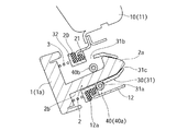
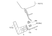
図4に示すように、取付板部12には、フック部2に対応させて、複数の取付孔12aが形成されている。この取付孔12aには、図4、図6、図8に示すように、環状のダンパーゴム20が嵌合、保持されている。このダンパーゴム20の外周には、例えば金属あるいは硬質合成樹脂からなる環状のスペーサ21が嵌合されている。スペーサ21により、ダンパーゴム20が過剰に震動することを制限し、ダンパーゴム20の拡径方向への弾性変形や変動が規制される。
As shown in FIG. 4, a plurality of mounting
取付孔12aに対応させて、フック部2が挿入される筒状のガイド部材30が設けられている。ガイド部材30の詳細が、図4、図11、図12に示される。ガイド部材30は、ダンパーゴム20内をがたつきなく挿通可能な本体部31と、その一端部側に形成されたフランジ部32と、を有する。上記本体部31を、前方側(ステアリングハンドル側)からダンパーゴム20内に挿入したとき、フランジ32が取付孔12a(ダンパーゴム20)の縁部に当接することにより、それ以上の挿入が規制される。
A
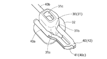
ガイド部材30の本体部31の両側面には、後述するロックばねを保持するために、保持孔31aと31bとが形成されている。また、ガイド部材30の先端部(フランジ部32とは反対側の端部)は、挿入されたフック部2の先端部を覆うように略キャップ状に形成されている。
Holding
取付板部12には、ガイド部材30を利用して、ロックばね40が保持されている。ロックばね40は、取付板部12を挟んで、ガイド部材30のフランジ部32とは反対側の位置に配設される。ロックばね40は、実施形態では、ばね材をU字状に曲げ加工することにより形成された芯材41と、芯材41をほぼ全体的に被覆する被覆材42とにより構
成されている。被覆材42は、例えば軟質あるいは硬質の合成樹脂により形成されている。
The
ロックばね40(の芯材41)は、互いに対向して伸びる一対の棒状部40a、40bと、一対の棒状部40aと40bとの板部同士を連結する連結部40cとを有する。棒状部40aに比して、棒状部40bが長く形成されている。そして、ロックばね40(の被覆材42)には、その長手方向に間隔をあけて一対の係止爪部40dが形成されている。
The lock spring 40 (core material 41) has a pair of rod-shaped
一対の棒状部40a、40bは、ガイド部材30の本体部31の側面に保持されている。すなわち、一方の棒状部40aが、本体部31に形成された保持孔31aに嵌合されて、その係止爪部40dによって本体部31をその径方向から支持している。この嵌合状態で、係止爪部40dの係止作用によって、本体部31に対して、一対の棒状部40a、40bがその長手方向に相対変位することが規制される。
The pair of rod-shaped
ロックばね40のうち他方の棒状部40bが、本体部31に形成された保持孔31bに嵌合されて、ガイド部材31内に大きく突出している(図6、図8参照)。すなわち、他方の棒状部40bは、ガイド部材31内を横断するように(フック部2の挿入軌跡と干渉するように)配設されている。外力を受けない状態において、一対の棒状部40aと40bとの間隔が、フック部2の拡大先端部2aの最大幅よりも小さく、かつフック部2のうち平坦面2b部分での幅よりも若干大きくなるように設定されている。なお、保持孔31a、31bに対する棒状部40a、40bの嵌合は、隙間を有する嵌合とされて、ガイド部材30に対してロックばね40がわずかに動き得るようにされている。
The other rod-shaped
次に、エアバッグモジュール10をステアリングハンドル(の芯金1)に対して取付ける手順について説明する。取付けの前準備として、エアバッグモジュール10の取付板部12に対して、ダンパーゴム20、スペーサ21、ガイド部材30、ロックばね40があらかじめ組み付けられた状態とされる。また、ステアリングハンドル側では、フック部2にリターンスプリング3が嵌合された状態とされ、またホーンセンサ4が固定された状態とされる。
Next, a procedure for attaching the
上述の前準備が完了した状態で、エアバッグモジュール10を、ステアリングハンドル(の芯金1)に対して接近させて、フック部2をガイド部材30内に挿入させていく。
With the above-mentioned preparation completed, the
ダンパーゴム20内に挿入されたフック部2は、やがてその拡大先端部2aが、ロックばね40における一対の棒状部40aと40bとの間隔が大きくなるように弾性変形させつつ、拡大先端部2aが一対の棒状部40a、40bを乗り越える。拡大先端部2aが一対の棒状部40a、40bを乗り越えた時点で、ロックばね40は、一対の棒状部40aと40bとの間隔が小さくなるように弾性復帰される。これにより、フック部2は、その拡大先端部2a部分でもってロックばね40に係止されて、ガイド部材30からの抜けが規制される。
The
ロックばね40によってフック部2の抜けが規制された状態で、エアバッグモジュール10のステアリングハンドル(に芯金1)に対する組付が完了される。すなわち、取付孔12a(ダンパーゴム20)に対してフック部2を挿入するというスナップイン方式で、エアバッグモジュール10が簡単にステアリングハンドルに取付けられることになる。このとき、フック部2の平坦面2bにロックばね40(の棒状部40a)が対向して、回り止めが行われる。
The assembly of the
エアバッグモジュール10は、フック部2の長手方向に所定範囲だけ相対変位可能とされる。そして、リターンスプリング3によって、通常は、後方側のストローク端に位置さ
れる(図6、図7参照)。この状態で、運転者が、リターンスプリング3の付勢力に抗してエアバッグモジュール10を押圧操作(前方へ向けて押す操作)すると、エアバッグモジュール10が前方へ移動して、取付板部12に設けた押圧部12bが、ステアリングハンドル側に設けたホーンセンサ4に当接して、ホーンが作動される(警報音の発生)。
The
走行中、ステアリングハンドルが振動すると、ダンパーゴム20の弾性とエアバッグモジュール10を質量体とを利用したダイナミックダンパ機能が発揮されて、ステアリングハンドルの振動が低減される。取付板部12とロックばね40との間に隙間が設定されていることから、ステアリングハンドルからの振動が、フック部2(これを覆うガイド部材30)を介してロックばね40に伝達することを防止しつつ、ダンパーゴム20の弾性変形を利用したダイナミックダンパ機能が確保される。
When the steering handle vibrates during traveling, the elasticity of the
スペーサ21によって、ダンパーゴム20が過剰に震動し不必要に拡径方向に弾性変形することが規制され、ダイナミックダンパ機能を効果的に得ることが可能となる。
The
車両の衝突に起因してエアバッグモジュール10が作動すると、運転者に向けてエアバッグが膨張展開される。膨張展開されたエアバッグは、ガイド部材30によって、フック部2(の先端部)に直接当接することが規制される。なお、実施形態では、本体部31の頂部に開口部31cを有するように設定してあるが、これは、空気抜きのためであり(フック部2の本体部31内へのスムーズな挿入確保)、この開口部31cを有しないものであってもよい。
When the
ここで、スペーサ21を別途設けないようにすることもできるが、取付孔12aを筒状に長く形成して、その内部にダンパーゴム20が存在するようにすることによって、スペーサ21の機能を兼用させることができる。
Here, although it is possible not to provide the
前述の説明から既に明かなように、スナップイン方式での取付けとダイナミックダンパ機能とを得るために要求される必要部品としては、実施形態では、フック部2、ダンパーゴム20、スペーサ21、ガイド部材30、ロックばね40の合計5点であり、スペーサ21を別途設けない場合は4点ですむことになる。
As is already clear from the above description, the necessary parts required to obtain the snap-in method mounting and the dynamic damper function include, in the embodiment, the
図15、図16は、本発明の第2の実施形態を示すもので、前記実施形態と同一構成要素には同一符号を付して、その重複した説明は省略する。本実施形態では、ガイド部材30のうち本体部31の外周面に、その全周にわたって延びる環状の凸部31dを形成してある。この凸部31dがダンパーゴム20の内周面に当接して、ガイド部材30の位置決めがより十分に行われる。
15 and 16 show a second embodiment of the present invention, and the same components as those of the embodiment are designated by the same reference numerals, and duplicate description thereof will be omitted. In the present embodiment, an annular
本体部31の外周面とダンパーゴム20の内周面との間には、凸部31dの周囲において隙間S1が形成される。この隙間S1の形成によって、周方向のダンピング可動域が拡大されて、ダイナミックダンパ性能を向上できる。なお、凸部31dの形成位置は、ダンパーゴム20の軸線方向略中間位置に形成しておくのが好ましい(ダンパーゴム20の軸線方向において、凸部31dを境にして隙間S1を略等しい長さで存在させる)。なお、本実施形態では、取付板部12に対して、外周縁部に開口されるスリット12cを周方向に間隔をあけて複数形成してある。
A gap S1 is formed around the
本実施形態ではさらに、ガイド部材30におけるフランジ部32部分において、ダンパーゴム20との間に隙間S2を形成してある。すなわち、フランジ部32は、ダンパーゴム20に対向する面が、径方向外側に向かうにつれて徐々にダンパーゴム20から離間するように傾斜されていて、隙間S2がくさび形状として形成されている。この隙間S2の形成により、ダンパーゴム20の可動域を広げて、ダイナミックダンパ性能を向上できる
。
In the present embodiment, a gap S2 is further formed between the
以上実施形態について説明したが、本発明は、実施形態に限定されるものではなく、特許請求の範囲の記載された範囲において適宜の変更が可能である。ダンパーゴム20を、ガイド部材30の外周に嵌合しておくこともできる(例えばガイド部材30の外周に環状の保持溝を形成して、この保持溝にダンパーゴム20を嵌合させておく)。フック部2は、芯金1と別部材で形成して、固定具によって芯金1に一体化することもできる。ガイド部材30は、フック部2の拡大先端部2aを覆うことのない形状に設定することもできる。勿論、本発明の目的は、明記されたものに限らず、実質的に好ましいあるいは利点として表現されたものを提供することをも暗黙的に含むものである。
Although the embodiments have been described above, the present invention is not limited to the embodiments, and appropriate modifications can be made within the scope of the claims. The
本発明は、ダイナミックダンパ機能を得つつスナップイン方式での取付けを行う場合に、部品点数が少ない簡単な構造とすることができる。 INDUSTRIAL APPLICABILITY The present invention can have a simple structure with a small number of parts when mounting by the snap-in method while obtaining the dynamic damper function.
1:芯金(ステアリングハンドル)
1a:ボス部
2:フック部
2a:拡大先端部
2b:平坦面
3:リターンスプリング
4:ホーンセンサ
10:エアバッグモジュール
11:本体部
12:取付板部
12a:取付孔
20:ダンパーゴム
21:スペーサ
30:ガイド部材
31:本体部
31a、31b:保持孔
31c:開口部
31d:凸部(図15、図16)
32:フランジ部
40:ロックばね
40a、40b:棒状部
40c:連結部
40d:係止爪部
S1、S2:隙間(図15、図16)
1: Core metal (steering handle)
1a: Boss part 2:
32: Flange portion 40:
Claims (10)
前記フック部が挿入される筒状のガイド部材が、環状のダンパーゴム内に前記ステアリングハンドル側から挿通可能とされて前記取付孔に嵌合、保持された本体部と、前記本体部の一端部側において形成されて前記取付孔のうち前記ステアリングハンドル側の縁部に係止されるフランジ部と、を有し、
前記本体部に、前記ガイド部材に挿入された前記フック部を係止して、該フック部の抜けを規制するロックばねが保持され、
前記ロックばねによって前記フック部を係止している状態において、該ロックばねと前記取付板部との間に、該フック部の断面方向において隙間が形成されている、
ことを特徴とするステアリングハンドル構造。 The steering handle structure is such that the airbag module is attached to the steering handle by inserting the hook portion formed in the steering handle into the mounting hole formed in the mounting plate portion of the airbag module. ,
A tubular guide member into which the hook portion is inserted is made to be able to be inserted into the annular damper rubber from the steering handle side, and is fitted and held in the mounting hole, and one end portion of the main body portion. It has a flange portion formed on the side and locked to the edge portion on the steering wheel side of the mounting holes.
A lock spring that locks the hook portion inserted into the guide member and restricts the hook portion from coming off is held in the main body portion .
In a state where the hook portion is locked by the lock spring, a gap is formed between the lock spring and the mounting plate portion in the cross-sectional direction of the hook portion.
The steering wheel structure is characterized by this.
前記ロックばねは、前記取付板部を挟んで前記フランジ部とは反対側の位置において前記本体部に保持されており、
前記ガイド部材は、前記フランジ部と前記ロックばねとによって、前記取付孔の軸線方向に移動して前記本体部が該取付孔から抜けることが規制されている、
ことを特徴とするステアリングハンドル構造。 Oite to claim 1,
The lock spring is held by the main body portion at a position opposite to the flange portion across the mounting plate portion.
The guide member is regulated by the flange portion and the lock spring so as to move in the axial direction of the mounting hole and the main body portion to come out of the mounting hole.
The steering wheel structure is characterized by this.
前記ロックばねは、略U字状に形成されることにより対向して伸びる一対の棒状部と、該一対の棒状部の一端部同士を連結する連結部と、を有し、
前記ロックばねは、前記一対の棒状部のうち少なくとも一方の棒状部が前記ガイド部材内を横断するようにして該ガイド部材に保持され、
前記ガイド部材に挿入された前記フック部が、前記一対の棒状部の間隔を拡大方向に弾性変形させつつ該一対の棒状部を乗り越えて、該一対の棒状部を乗り越えた後に該一対の棒状部がその間隔が狭くなるように弾性復帰することにより、該フック部の該ロックばねからの抜けが規制されるように設定されている、
ことを特徴とするステアリングハンドル構造。 In claim 1 or 2 ,
The lock spring has a pair of rod-shaped portions that are formed in a substantially U shape and extend so as to face each other, and a connecting portion that connects one ends of the pair of rod-shaped portions.
The lock spring is held by the guide member so that at least one of the pair of rod-shaped portions traverses the guide member.
The hook portion inserted into the guide member overcomes the pair of rod-shaped portions while elastically deforming the distance between the pair of rod-shaped portions in the expanding direction, and after overcoming the pair of rod-shaped portions, the pair of rod-shaped portions. Is set so that the hook portion is restricted from coming off from the lock spring by elastically returning so that the interval is narrowed.
The steering wheel structure is characterized by this.
前記本体部の両側面にはそれぞれ保持孔が形成され、 Holding holes are formed on both side surfaces of the main body.
前記一対の棒状部の一方が前記保持孔の一方に嵌合されると共に、該一対の棒状部の他方が該保持孔の他方に嵌合されている、 One of the pair of rod-shaped portions is fitted to one of the holding holes, and the other of the pair of rod-shaped portions is fitted to the other of the holding holes.
ことを特徴とするステアリングハンドル構造。The steering wheel structure is characterized by this.
前記フック部の側面のうち前記ロックばねに対面する少なくとも1つの面が、平坦面に形成されている、ことを特徴とするステアリングハンドル構造。 In any one of claims 1 to 4,
A steering handle structure characterized in that at least one surface of the side surface of the hook portion facing the lock spring is formed as a flat surface.
前記ガイド部材の端部によって、前記ロックばねによって係止されている状態における前記フック部の先端部が覆われている、ことを特徴とするステアリングハンドル構造。 In any one of claims 1 to 5,
The steering handle structure is characterized in that the end portion of the guide member covers the tip end portion of the hook portion in a state of being locked by the lock spring.
前記ダンパーゴムの外周に、該ダンパーゴムが拡径する方向への弾性変形を規制するスペーサが嵌合されている、ことを特徴とするステアリングハンドル構造。 In any one of claims 1 to 6,
A steering handle structure characterized in that a spacer that regulates elastic deformation in the direction in which the damper rubber expands in diameter is fitted on the outer periphery of the damper rubber.
前記エアバッグモジュールは、前記フック部が前記ロックばねによって係止されている状態で、該フック部の長手方向に所定範囲内で変位可能とされ、
リターンスプリングにより、前記エアバッグモジュールが前記ステアリングハンドルから離間する方向に付勢されている、
ことを特徴とするステアリングハンドル構造。 In any one of claims 1 to 7,
The airbag module can be displaced within a predetermined range in the longitudinal direction of the hook portion in a state where the hook portion is locked by the lock spring.
The return spring urges the airbag module in a direction away from the steering handle.
The steering wheel structure is characterized by this.
前記フック部が挿入される筒状のガイド部材が、環状のダンパーゴムを介して前記取付孔に嵌合、保持され、
前記ガイド部材に、前記ガイド部材に挿入された前記フック部を係止して、該フック部の抜けを規制するロックばねが保持され、
前記ガイド部材は、前記ダンパーゴム内に前記ステアリングハンドル側から挿通可能な本体部と、該本体部の一端部側に形成され、前記取付孔のうち前記ステアリングハンドル側の縁部に係止されるフランジ部と、を有し、
前記ロックばねは、前記取付板部を挟んで前記フランジ部とは反対側の位置において前記本体部に保持されており、
前記ガイド部材は、前記フランジ部と前記ロックばねとによって、前記取付孔の軸線方向に移動して前記本体部が該取付孔から抜けることが規制され、
前記本体部の外周面に前記ダンパーゴムの内周面に当接する凸部が形成されて、該ガイド部材と該ダンパーゴムとの間には該凸部の周囲において隙間が形成されている、ことを特徴とするステアリングハンドル構造。 The steering handle structure is such that the airbag module is attached to the steering handle by inserting the hook portion formed in the steering handle into the mounting hole formed in the mounting plate portion of the airbag module. ,
A tubular guide member into which the hook portion is inserted is fitted and held in the mounting hole via an annular damper rubber.
A lock spring that locks the hook portion inserted into the guide member to the guide member and restricts the hook portion from coming off is held.
The guide member is formed in the damper rubber with a main body portion that can be inserted from the steering handle side and one end side of the main body portion, and is locked to the edge portion of the mounting hole on the steering handle side. With a flange part,
The lock spring is held by the main body portion at a position opposite to the flange portion across the mounting plate portion.
The guide member is restricted from moving in the axial direction of the mounting hole by the flange portion and the lock spring so that the main body portion comes out of the mounting hole.
A convex portion that abuts on the inner peripheral surface of the damper rubber is formed on the outer peripheral surface of the main body portion, and a gap is formed around the convex portion between the guide member and the damper rubber. The steering wheel structure is characterized by.
前記フランジ部と該フランジ部に対向する前記ダンパーゴムとの間に隙間が形成されている、ことを特徴とするステアリングハンドル構造。
In claim 1 or 9,
A steering handle structure characterized in that a gap is formed between the flange portion and the damper rubber facing the flange portion.
Priority Applications (6)
| Application Number | Priority Date | Filing Date | Title |
|---|---|---|---|
| JP2017045625A JP6835633B2 (en) | 2017-03-10 | 2017-03-10 | Steering handle structure |
| KR1020197028677A KR102497093B1 (en) | 2017-03-10 | 2018-02-08 | steering handle structure |
| CN201880017256.XA CN110431050B (en) | 2017-03-10 | 2018-02-08 | Steering wheel structure |
| PCT/JP2018/004292 WO2018163698A1 (en) | 2017-03-10 | 2018-02-08 | Steering wheel structure |
| US16/492,269 US10875564B2 (en) | 2017-03-10 | 2018-02-08 | Steering wheel structure |
| DE112018000782.0T DE112018000782T5 (en) | 2017-03-10 | 2018-02-08 | STEERING WHEEL ASSEMBLY |
Applications Claiming Priority (1)
| Application Number | Priority Date | Filing Date | Title |
|---|---|---|---|
| JP2017045625A JP6835633B2 (en) | 2017-03-10 | 2017-03-10 | Steering handle structure |
Publications (2)
| Publication Number | Publication Date |
|---|---|
| JP2018149837A JP2018149837A (en) | 2018-09-27 |
| JP6835633B2 true JP6835633B2 (en) | 2021-02-24 |
Family
ID=63448638
Family Applications (1)
| Application Number | Title | Priority Date | Filing Date |
|---|---|---|---|
| JP2017045625A Active JP6835633B2 (en) | 2017-03-10 | 2017-03-10 | Steering handle structure |
Country Status (6)
| Country | Link |
|---|---|
| US (1) | US10875564B2 (en) |
| JP (1) | JP6835633B2 (en) |
| KR (1) | KR102497093B1 (en) |
| CN (1) | CN110431050B (en) |
| DE (1) | DE112018000782T5 (en) |
| WO (1) | WO2018163698A1 (en) |
Families Citing this family (16)
| Publication number | Priority date | Publication date | Assignee | Title |
|---|---|---|---|---|
| US11718257B2 (en) * | 2016-12-15 | 2023-08-08 | Zf Passive Safety Systems Us Inc | Coupling device for mounting an airbag module to be oscillating on a vehicle steering wheel |
| DE102016124530A1 (en) * | 2016-12-15 | 2018-06-21 | Trw Automotive Safety Systems Gmbh | Coupling device for vibratory mounting of a gas bag module to a vehicle steering wheel |
| DE102017102463A1 (en) * | 2017-02-08 | 2018-08-09 | Trw Automotive Safety Systems Gmbh | BEARING UNIT, STEERING WHEEL ASSEMBLY AND METHOD FOR MANUFACTURING A VEHICLE ASSEMBLY GROUP |
| JP7015194B2 (en) * | 2018-03-19 | 2022-02-02 | 芦森工業株式会社 | Steering wheel |
| CN112351929B (en) * | 2018-06-25 | 2022-08-30 | 奥托立夫开发公司 | Mounting and fixing structure of damper unit in steering wheel and steering wheel |
| JP6953371B2 (en) * | 2018-08-21 | 2021-10-27 | 株式会社三共 | Pachinko machine |
| US10926698B2 (en) * | 2018-12-17 | 2021-02-23 | Key Safety Systems, Inc. | Integrated steering wheel, vibration absorber, and driver airbag |
| KR102693552B1 (en) * | 2019-04-11 | 2024-08-08 | 현대모비스 주식회사 | Driver seat airbag |
| FR3099437B1 (en) * | 2019-07-29 | 2025-02-21 | Autoliv Dev | Removable mounting device for an airbag module on a steering wheel |
| WO2021145150A1 (en) * | 2020-01-16 | 2021-07-22 | オートリブ ディベロップメント エービー | Steering wheel device for vehicle |
| JP7410821B2 (en) | 2020-08-19 | 2024-01-10 | Joyson Safety Systems Japan合同会社 | steering wheel |
| CN112092895B (en) * | 2020-09-30 | 2025-05-23 | 浙江吉利控股集团有限公司 | Automobile steering wheel damping unit and automobile steering wheel |
| CN117157225A (en) * | 2021-04-15 | 2023-12-01 | 奥托立夫开发公司 | Steering wheel |
| DE202021104137U1 (en) * | 2021-08-03 | 2022-11-08 | Dalphi Metal Espana, S.A. | Gas bag module and vehicle steering unit with such a gas bag module |
| KR20240033489A (en) * | 2022-09-05 | 2024-03-12 | 현대자동차주식회사 | Steering wheel and damper unit of the steering wheel |
| USD1089002S1 (en) * | 2023-12-04 | 2025-08-19 | Stay Tuned Performance | Steering wheel |
Family Cites Families (15)
| Publication number | Priority date | Publication date | Assignee | Title |
|---|---|---|---|---|
| US5087069A (en) * | 1990-12-20 | 1992-02-11 | General Motors Corporation | Restraint system mounting |
| DE29805210U1 (en) * | 1998-03-23 | 1998-06-04 | TRW Automotive Safety Systems GmbH, 63743 Aschaffenburg | Impact protection device |
| DE29805207U1 (en) * | 1998-03-23 | 1998-06-04 | TRW Automotive Safety Systems GmbH, 63743 Aschaffenburg | Steering wheel with an airbag |
| JP2001233159A (en) * | 2000-02-18 | 2001-08-28 | Tokai Rika Co Ltd | Air bag device assembling structure |
| EP1418095B1 (en) * | 2000-06-27 | 2006-04-26 | Toyoda Gosei Co., Ltd. | Steering wheel with an airbag device |
| US6874808B2 (en) * | 2002-09-20 | 2005-04-05 | Delphi Technologies, Inc. | Apparatus and method for maintaining a uniform gap between an airbag module and its surrounding structure |
| US7510209B2 (en) * | 2004-09-10 | 2009-03-31 | Delphi Technologies, Inc. | Airbag module with integral locking mechanism and method of making |
| JP5153526B2 (en) * | 2008-02-01 | 2013-02-27 | 本田技研工業株式会社 | Steering wheel vibration reduction structure |
| JP5872237B2 (en) * | 2011-10-07 | 2016-03-01 | 芦森工業株式会社 | Mounting structure of airbag device |
| JP5989449B2 (en) * | 2012-08-06 | 2016-09-07 | タカタ株式会社 | Steering wheel |
| JP6040884B2 (en) | 2012-11-12 | 2016-12-07 | 豊田合成株式会社 | Steering wheel damping structure |
| JP6454073B2 (en) * | 2014-02-03 | 2019-01-16 | Joyson Safety Systems Japan株式会社 | Steering wheel |
| JP6488627B2 (en) | 2014-02-28 | 2019-03-27 | Joyson Safety Systems Japan株式会社 | Steering wheel |
| JP6164175B2 (en) | 2014-07-30 | 2017-07-19 | 豊田合成株式会社 | Steering wheel |
| KR102293578B1 (en) * | 2015-07-22 | 2021-08-25 | 현대모비스 주식회사 | Steering wheel air bag apparatus |
-
2017
- 2017-03-10 JP JP2017045625A patent/JP6835633B2/en active Active
-
2018
- 2018-02-08 WO PCT/JP2018/004292 patent/WO2018163698A1/en not_active Ceased
- 2018-02-08 CN CN201880017256.XA patent/CN110431050B/en active Active
- 2018-02-08 US US16/492,269 patent/US10875564B2/en active Active
- 2018-02-08 KR KR1020197028677A patent/KR102497093B1/en active Active
- 2018-02-08 DE DE112018000782.0T patent/DE112018000782T5/en active Pending
Also Published As
| Publication number | Publication date |
|---|---|
| JP2018149837A (en) | 2018-09-27 |
| CN110431050B (en) | 2022-03-25 |
| KR102497093B1 (en) | 2023-02-06 |
| WO2018163698A1 (en) | 2018-09-13 |
| KR20190125386A (en) | 2019-11-06 |
| US20200331511A1 (en) | 2020-10-22 |
| US10875564B2 (en) | 2020-12-29 |
| DE112018000782T5 (en) | 2019-11-07 |
| CN110431050A (en) | 2019-11-08 |
Similar Documents
| Publication | Publication Date | Title |
|---|---|---|
| JP6835633B2 (en) | Steering handle structure | |
| JP5797770B2 (en) | Steering wheel vibration reduction structure | |
| WO2012032860A1 (en) | Steering wheel structure with airbag module | |
| JP7045967B2 (en) | Damper structure for the steering wheel of the vehicle | |
| WO2017154571A1 (en) | Damper unit for airbag module and steering wheel | |
| JP6817872B2 (en) | Mounting structure of airbag device | |
| JP5523996B2 (en) | Steering wheel structure with airbag module | |
| US12522275B2 (en) | Steering wheel and method of manufacturing same | |
| CN114750720B (en) | Support structure of air bag device | |
| CN212354123U (en) | Steering wheel vibration damping system and steering wheel | |
| JP6871783B2 (en) | Airbag device | |
| JP4363485B2 (en) | Steering column cover structure | |
| JP6197201B2 (en) | Airbag mounting structure | |
| JP4274094B2 (en) | Steering wheel | |
| JP2007309420A (en) | Structure for connecting interior member and body panel of automobile to each other | |
| JP5139212B2 (en) | Airbag device for vehicle | |
| JP6341817B2 (en) | Inner mirror structure for vehicles | |
| JP7269819B2 (en) | Decorative member and module cover body | |
| JP2019156346A (en) | Steering wheel | |
| CN113815708A (en) | Steering wheel damping system and steering wheel | |
| KR101962211B1 (en) | Protection cover for car speaker | |
| JP5104521B2 (en) | Door interior material | |
| JPH0769154A (en) | Installation structure for air bag device | |
| JPH0728751U (en) | Airbag device with inflator cover | |
| JP2008069825A (en) | Ea material and mounting structure thereof |
Legal Events
| Date | Code | Title | Description |
|---|---|---|---|
| A621 | Written request for application examination |
Free format text: JAPANESE INTERMEDIATE CODE: A621 Effective date: 20200121 |
|
| A131 | Notification of reasons for refusal |
Free format text: JAPANESE INTERMEDIATE CODE: A131 Effective date: 20200918 |
|
| A601 | Written request for extension of time |
Free format text: JAPANESE INTERMEDIATE CODE: A601 Effective date: 20201112 |
|
| A521 | Request for written amendment filed |
Free format text: JAPANESE INTERMEDIATE CODE: A523 Effective date: 20210114 |
|
| TRDD | Decision of grant or rejection written | ||
| A01 | Written decision to grant a patent or to grant a registration (utility model) |
Free format text: JAPANESE INTERMEDIATE CODE: A01 Effective date: 20210129 |
|
| A61 | First payment of annual fees (during grant procedure) |
Free format text: JAPANESE INTERMEDIATE CODE: A61 Effective date: 20210204 |
|
| R150 | Certificate of patent or registration of utility model |
Ref document number: 6835633 Country of ref document: JP Free format text: JAPANESE INTERMEDIATE CODE: R150 |
|
| R250 | Receipt of annual fees |
Free format text: JAPANESE INTERMEDIATE CODE: R250 |
|
| R250 | Receipt of annual fees |
Free format text: JAPANESE INTERMEDIATE CODE: R250 |
|
| R250 | Receipt of annual fees |
Free format text: JAPANESE INTERMEDIATE CODE: R250 |