JP6835552B2 - Hydraulic control unit for brake system for vehicles - Google Patents

Hydraulic control unit for brake system for vehicles Download PDF

Info

Publication number
JP6835552B2
JP6835552B2 JP2016234635A JP2016234635A JP6835552B2 JP 6835552 B2 JP6835552 B2 JP 6835552B2 JP 2016234635 A JP2016234635 A JP 2016234635A JP 2016234635 A JP2016234635 A JP 2016234635A JP 6835552 B2 JP6835552 B2 JP 6835552B2
Authority
JP
Japan
Prior art keywords
flow path
dome
hydraulic pressure
control unit
shaped film
Prior art date
Legal status (The legal status is an assumption and is not a legal conclusion. Google has not performed a legal analysis and makes no representation as to the accuracy of the status listed.)
Active
Application number
JP2016234635A
Other languages
Japanese (ja)
Other versions
JP2018090073A (en
Inventor
照剛 三好
照剛 三好
吉朗 赤田
吉朗 赤田
Current Assignee (The listed assignees may be inaccurate. Google has not performed a legal analysis and makes no representation or warranty as to the accuracy of the list.)
Robert Bosch GmbH
Original Assignee
Robert Bosch GmbH
Priority date (The priority date is an assumption and is not a legal conclusion. Google has not performed a legal analysis and makes no representation as to the accuracy of the date listed.)
Filing date
Publication date
Application filed by Robert Bosch GmbH filed Critical Robert Bosch GmbH
Priority to JP2016234635A priority Critical patent/JP6835552B2/en
Publication of JP2018090073A publication Critical patent/JP2018090073A/en
Application granted granted Critical
Publication of JP6835552B2 publication Critical patent/JP6835552B2/en
Active legal-status Critical Current
Anticipated expiration legal-status Critical

Links

Images

Landscapes

  • Braking Systems And Boosters (AREA)

Description

本発明は、使用者のブレーキシステムの使用感を向上することができる、車両用のブレーキシステムの液圧制御ユニットに関する。 The present invention relates to a hydraulic control unit of a brake system for a vehicle, which can improve the usability of the brake system of a user.

従来の車両用のブレーキシステムとして、マスタシリンダとホイールシリンダとを連通させる主流路と、主流路のブレーキ液を逃がす副流路と、副流路の途中部にブレーキ液を供給する供給流路と、有する液圧回路を備えているものがある(例えば、特許文献1を参照。)。 As a conventional brake system for a vehicle, a main flow path for communicating the master cylinder and the wheel cylinder, a sub-flow path for releasing the brake fluid in the main flow path, and a supply flow path for supplying the brake fluid in the middle of the sub-flow path. Some have a hydraulic circuit (see, for example, Patent Document 1).

例えば、副流路の上流側端部は、主流路のうちの、込め弁を基準とするホイールシリンダ側の領域に接続されており、副流路の下流側端部は、主流路のうちの、込め弁を基準とするマスタシリンダ側の領域に接続されている。また、供給流路の上流側端部は、マスタシリンダに連通し、供給流路の下流側端部は、副流路のうちの、弛め弁を基準とする下流側の領域であって、且つ、その領域に設けられているポンプの吸込側に接続されている。また、主流路のうちの、副流路の下流側端部との接続部を基準とするマスタシリンダ側の領域に、第1切換弁が設けられており、供給流路の途中部に第2切換弁が設けられている。 For example, the upstream end of the sub-flow path is connected to the wheel cylinder side region of the main flow path with reference to the filling valve, and the downstream end of the sub-flow path is of the main flow path. , It is connected to the area on the master cylinder side with respect to the filling valve. Further, the upstream end of the supply flow path communicates with the master cylinder, and the downstream end of the supply flow path is a region of the secondary flow path on the downstream side with respect to the loosening valve. Moreover, it is connected to the suction side of the pump provided in that area. Further, a first switching valve is provided in a region of the main flow path on the master cylinder side with reference to a connection portion with the downstream end of the sub flow path, and a second switching valve is provided in the middle of the supply flow path. A switching valve is provided.

例えば、込め弁、弛め弁、ポンプ、第1切換弁、及び第2切換弁と、それらが組み込まれている基体と、それらの動作を司る制御器によって、液圧制御ユニットが構成される。液圧制御ユニットにおいて、込め弁、弛め弁、ポンプ、第1切換弁、及び第2切換弁の動作が制御されることで、液圧回路の液圧が制御される。 For example, the hydraulic pressure control unit is composed of a filling valve, a loosening valve, a pump, a first switching valve, a second switching valve, a substrate on which they are incorporated, and a controller that controls their operation. In the hydraulic pressure control unit, the hydraulic pressure of the hydraulic pressure circuit is controlled by controlling the operations of the filling valve, the loosening valve, the pump, the first switching valve, and the second switching valve.

特に、ブレーキシステムの入力部(例えばブレーキペダル等)におけるブレーキ操作の状態に関わらず、ホイールシリンダのブレーキ液の液圧を上昇させる必要が生じた際には、込め弁が開き、弛め弁が閉じ、第1切換弁が閉じ、且つ、第2切換弁が開いた状態で、ポンプが駆動される。 In particular, when it becomes necessary to increase the hydraulic pressure of the brake fluid of the wheel cylinder regardless of the state of brake operation at the input part of the brake system (for example, the brake pedal), the filling valve opens and the release valve opens. The pump is driven with the first switching valve closed and the second switching valve open.

特開2006−1534号公報(段落[0015])Japanese Unexamined Patent Publication No. 2006-1534 (paragraph [0015])

第2切換弁が開いた状態でポンプが駆動されると、ブレーキ液に生じた脈動が、供給流路及びマスタシリンダを介して、ブレーキシステムの入力部に伝搬することとなって、使用者に違和感を与えてしまう。特に、昨今のブレーキシステムでは、車両へのブレーキシステムの搭載性の向上を目的として、倍力装置が小型化又は省略される場合があり、そのような場合には、使用者がブレーキシステムの入力部を操作している(例えば、使用者がブレーキペダルを踏んでいる)際に、第2切換弁が開いた状態でポンプが駆動される場合が生じることとなって、その脈動の影響が看過できなくなってしまう。つまり、上述の液圧制御ユニットでは、使用者のブレーキシステムの使用感が悪化してしまう場合が生じるという問題点がある。 When the pump is driven with the second switching valve open, the pulsation generated in the brake fluid propagates to the input part of the brake system via the supply flow path and the master cylinder, and the user is informed. It gives a sense of discomfort. In particular, in recent brake systems, the booster may be miniaturized or omitted for the purpose of improving the mountability of the brake system on a vehicle. In such a case, the user inputs the brake system. When operating the part (for example, the user is stepping on the brake pedal), the pump may be driven with the second switching valve open, and the effect of the pulsation is overlooked. I can't do it. That is, the above-mentioned hydraulic pressure control unit has a problem that the usability of the brake system of the user may be deteriorated.

本発明は、上述の課題を背景としてなされたものであり、使用者のブレーキシステムの使用感を向上することができる液圧制御ユニットを得るものである。 The present invention has been made against the background of the above-mentioned problems, and obtains a hydraulic pressure control unit capable of improving the usability of a user's brake system.

本発明に係る液圧制御ユニットは、車両用のブレーキシステムの液圧制御ユニットであって、前記ブレーキシステムは、マスタシリンダとホイールシリンダとを連通させる主流路と、前記主流路のブレーキ液を逃がす副流路と、前記副流路の途中部である第1途中部にブレーキ液を供給する供給流路と、を有する液圧回路を含み、前記副流路の下流側端部である第1下流側端部は、前記主流路の途中部である第2途中部に接続されており、前記供給流路の上流側端部である第1上流側端部は、前記マスタシリンダに連通し、前記副流路の上流側端部である第2上流側端部は、前記主流路のうちの前記第2途中部を基準として前記ホイールシリンダ側となる途中部である第3途中部に接続されており、前記液圧制御ユニットは、前記供給流路の一部を構成する内部流路、及び、連通口を介して該内部流路と連通する収容室を有する基体と、前記主流路のうちの前記第2途中部と前記第3途中部と間の領域に設けられている込め弁と、前記副流路において前記第2上流側端部と前記第1途中部との間となる領域に設けられている弛め弁と、前記副流路のうちの前記第1途中部と前記第1下流側端部との間の領域に設けられ、吸込側が該第1途中部に連通し、吐出側が該第1下流側端部に連通するポンプと、前記主流路のうちの前記第2途中部を基準とする前記マスタシリンダ側に設けられている第1切換弁と、前記供給流路に設けられている第2切換弁及びダンパユニットと、を備えており、前記ダンパユニットは、前記基体の前記収容室に収容され、前記基体に保持されている基部と、前記基部に立設され、内部に空間が形成され、側部に前記空間に通じる貫通穴が形成されているポール部と、を有する柱状体と、前記ポール部の先端部及び前記側部を覆うドーム状膜体と、を備えており、前記収容室にブレーキ液が充填されていない状態で、前記ドーム状膜体の内面と前記ポール部の前記側部の少なくとも一部との間に、隙間が形成されており、前記基体は、前記収容室の側部の内面に形成された凹部を備え、該凹部の底部に前記連通口が形成されており、前記ドーム状膜体が外面側に膨張するように変形した場合でも前記ドーム状膜体が前記凹部の周縁に当接しない構成となっているThe hydraulic pressure control unit according to the present invention is a hydraulic pressure control unit of a brake system for a vehicle, and the brake system releases a main flow path for communicating a master cylinder and a wheel cylinder and a brake fluid in the main flow path. A first that includes a hydraulic circuit having a sub-flow path and a supply flow path that supplies brake fluid to a first halfway portion that is an intermediate portion of the sub-flow path, and is a downstream end of the sub-flow path. The downstream end portion is connected to the second intermediate portion which is the intermediate portion of the main flow path, and the first upstream side end portion which is the upstream side end portion of the supply flow path communicates with the master cylinder. The second upstream end, which is the upstream end of the sub-flow path, is connected to the third intermediate, which is the middle of the main flow path and is on the wheel cylinder side with reference to the second intermediate. The hydraulic pressure control unit includes an internal flow path that forms a part of the supply flow path, a substrate having a storage chamber that communicates with the internal flow path via a communication port, and the main flow path. and said second intermediate portion and the third rice is provided in a region between the middle section valve, in a region to be a between the auxiliary flow said first intermediate portion and the second upstream end in path It is provided in the region between the provided loosening valve and the first intermediate portion and the first downstream end portion of the sub-flow path, and the suction side communicates with the first intermediate portion to discharge. A pump whose side communicates with the first downstream end, a first switching valve provided on the master cylinder side with reference to the second intermediate portion of the main flow path, and a supply flow path are provided. The second switching valve and the damper unit are provided, and the damper unit is housed in the storage chamber of the base and held in the base, and is erected in the base and inside. A columnar body having a pole portion having a space formed therein and a through hole leading to the space formed in a side portion thereof, and a dome-shaped membrane body covering the tip portion of the pole portion and the side portion. A gap is formed between the inner surface of the dome-shaped membrane body and at least a part of the side portion of the pole portion in a state where the accommodation chamber is not filled with the brake fluid, and the substrate is formed. Is provided with a recess formed on the inner surface of the side portion of the storage chamber, and the communication port is formed at the bottom of the recess, and even when the dome-shaped membrane body is deformed so as to expand toward the outer surface side, the said The dome-shaped membrane body does not come into contact with the peripheral edge of the recess .

本発明に係る液圧制御ユニットでは、供給流路にダンパユニットが設けられている。そのため、第2切換弁が開いた状態でポンプが駆動されることで生じる脈動が、供給流路及びマスタシリンダを介して、ブレーキシステムの入力部(例えばブレーキペダル等)に伝搬することが抑制される。 In the hydraulic pressure control unit according to the present invention, a damper unit is provided in the supply flow path. Therefore, the pulsation generated by driving the pump with the second switching valve open is suppressed from propagating to the input portion (for example, the brake pedal) of the brake system via the supply flow path and the master cylinder. To.

そして、ダンパユニットが、ポール部を有する柱状体と、ドーム状膜体と、を備えており、収容室にブレーキ液が充填されていない状態で、ドーム状膜体の内面とポール部の側部の少なくとも一部との間に隙間が形成されている構成である。ダンパユニットは、マスタシリンダに連通する供給流路、つまり、使用者のブレーキシステムの使用感に多大な影響を及ぼす箇所に設けられるものであり、高い減衰性能を有することが望まれる。一方、液圧制御ユニットが車両に搭載される場合には、そのサイズも重要視される。上述のダンパユニットは、受圧面の面積が三次元的に拡大される構造であるため、減衰性能の向上に伴う液圧制御ユニットの大型化が効率的に抑制される。すなわち、上述のダンパユニットは、車両用のブレーキシステムの、上流側端部がポンプの吸込側に連通し、下流側端部がマスタシリンダに連通する供給流路に設けられることが、特に好適なものであり、そのようなダンパユニットの採用によって、使用者のブレーキシステムの使用感を向上することの実現性が格段向上される。 The damper unit includes a columnar body having a pole portion and a dome-shaped membrane body, and the inner surface of the dome-shaped membrane body and the side portion of the pole portion are in a state where the accommodation chamber is not filled with the brake fluid. A gap is formed between the dome and at least a part of the dome. The damper unit is provided in a supply flow path communicating with the master cylinder, that is, a location that greatly affects the usability of the user's brake system, and is desired to have high damping performance. On the other hand, when the hydraulic pressure control unit is mounted on a vehicle, its size is also important. Since the damper unit described above has a structure in which the area of the pressure receiving surface is three-dimensionally expanded, it is possible to efficiently suppress the increase in size of the hydraulic pressure control unit due to the improvement in damping performance. That is, it is particularly preferable that the above-mentioned damper unit is provided in a supply flow path in which the upstream end of the vehicle brake system communicates with the suction side of the pump and the downstream end communicates with the master cylinder. By adopting such a damper unit, the feasibility of improving the usability of the brake system of the user is significantly improved.

ここで、本発明に係るダンパユニットは、ドーム状膜体の外面側の圧力(つまり収容室内のブレーキ液の液圧)と内面側の圧力との圧力差によって該ドーム状膜体が変形し、ポンプ駆動時に発生する脈動を減衰する構成となっている。このため、本発明に接した当業者は、ドーム状膜体の外面側の圧力が内面側の圧力よりも低下し、ドーム状膜体が外面側に膨張するように変形した際、ドーム状膜体が収容室と供給流路の一部を構成する内部流路との連通口に接触することを懸念するかもしれない。すなわち、本発明に接した当業者は、ドーム状膜体が連通口に接触することにより、連通口を閉塞して供給流路(換言すると液圧回路)内のブレーキ液の流れを阻害してしまう、ドーム状膜体が損傷してしまう等の課題が発生することを懸念するかもしれない。 Here, in the damper unit according to the present invention, the dome-shaped membrane body is deformed by the pressure difference between the pressure on the outer surface side (that is, the hydraulic pressure of the brake fluid in the accommodation chamber) and the pressure on the inner surface side of the dome-shaped membrane body. It is configured to attenuate the pulsation generated when the pump is driven. Therefore, those skilled in the art who have come into contact with the present invention will find that when the pressure on the outer surface side of the dome-shaped membrane body is lower than the pressure on the inner surface side and the dome-shaped membrane body is deformed to expand toward the outer surface side, the dome-shaped membrane body You may be concerned that your body will come into contact with the communication port between the containment chamber and the internal channels that form part of the supply channel. That is, those skilled in the art who have come into contact with the present invention block the communication port by contacting the dome-shaped membrane body with the communication port and obstruct the flow of brake fluid in the supply flow path (in other words, the hydraulic circuit). You may be concerned about problems such as damage to the dome-shaped membrane body.

しかしながら、本発明に係る液圧制御ユニットにおいては、収容室の内面に形成された凹部を備え、該凹部の底部に、収容室と供給流路の一部を構成する内部流路との連通口が形成されている。このため、本発明に係る液圧制御ユニットは、ドーム状膜体が外面側に膨張するように変形した場合でも、ドーム状膜体が連通口に接触することを抑制できる。すなわち、本発明に係る液圧制御ユニットは、ドーム状膜体が外面側に膨張するように変形した場合でも、連通口を閉塞して供給流路(換言すると液圧回路)内のブレーキ液の流れを阻害してしまう、ドーム状膜体が損傷してしまう等の課題の発生を抑制できる。 However, the hydraulic pressure control unit according to the present invention is provided with a recess formed on the inner surface of the storage chamber, and at the bottom of the recess, a communication port between the storage chamber and an internal flow path forming a part of the supply flow path is provided. Is formed. Therefore, the hydraulic pressure control unit according to the present invention can prevent the dome-shaped membrane body from coming into contact with the communication port even when the dome-shaped membrane body is deformed so as to expand toward the outer surface side. That is, the hydraulic pressure control unit according to the present invention closes the communication port and of the brake fluid in the supply flow path (in other words, the hydraulic pressure circuit) even when the dome-shaped membrane body is deformed so as to expand toward the outer surface side. It is possible to suppress the occurrence of problems such as obstructing the flow and damaging the dome-shaped membrane body.

本発明の実施の形態1に係るブレーキシステムの、システム構成の例を示す図である。It is a figure which shows the example of the system configuration of the brake system which concerns on Embodiment 1 of this invention. 本発明の実施の形態1に係るブレーキシステムの、システム構成の他の例を示す図である。It is a figure which shows another example of the system structure of the brake system which concerns on Embodiment 1 of this invention. 本発明の実施の形態1に係るブレーキシステムの、ダンパユニットの搭載状態を示す部分断面図である。It is a partial cross-sectional view which shows the mounting state of the damper unit of the brake system which concerns on Embodiment 1 of this invention. 図3におけるA−A線での断面図である。FIG. 3 is a cross-sectional view taken along the line AA in FIG. 本発明の実施の形態1に係るブレーキシステムの、ダンパユニットの詳細を示す断面図である。It is sectional drawing which shows the detail of the damper unit of the brake system which concerns on Embodiment 1 of this invention. 本発明の実施の形態1に係るブレーキシステムの、ダンパユニットの詳細を示す断面図である。It is sectional drawing which shows the detail of the damper unit of the brake system which concerns on Embodiment 1 of this invention. 本発明の実施の形態1に係るブレーキシステムの、ダンパユニットの搭載状態を示す部分断面図であり、ドーム状膜体が外面側に膨張するように変形した状態を示す図である。It is a partial cross-sectional view which shows the mounting state of the damper unit of the brake system which concerns on Embodiment 1 of this invention, and is the figure which shows the state which the dome-shaped film body is deformed so that it expands to the outer surface side. 本発明の実施の形態1に係るブレーキシステムの、システム構成の更に別の例を示す図である。It is a figure which shows still another example of the system structure of the brake system which concerns on Embodiment 1 of this invention. 図8に示すブレーキシステムの、ダンパユニットの搭載状態を示す部分断面図である。It is a partial cross-sectional view which shows the mounting state of the damper unit of the brake system shown in FIG. 本発明の実施の形態2に係るブレーキシステムの、ダンパユニットの詳細を示す断面図である。It is sectional drawing which shows the detail of the damper unit of the brake system which concerns on Embodiment 2 of this invention. 本発明の実施の形態2に係るブレーキシステムの、ダンパユニットの詳細を示す断面図である。It is sectional drawing which shows the detail of the damper unit of the brake system which concerns on Embodiment 2 of this invention. 本発明の実施の形態2に係るブレーキシステムの、ダンパユニットの詳細を示す断面図である。It is sectional drawing which shows the detail of the damper unit of the brake system which concerns on Embodiment 2 of this invention. 本発明の実施の形態2に係るブレーキシステムの、ダンパユニットの搭載状態を示す部分断面図である。It is a partial cross-sectional view which shows the mounting state of the damper unit of the brake system which concerns on Embodiment 2 of this invention. 本発明の実施の形態3に係るブレーキシステムの、ダンパユニットの詳細を示す断面図である。It is sectional drawing which shows the detail of the damper unit of the brake system which concerns on Embodiment 3 of this invention. 本発明の実施の形態3に係るブレーキシステムの、ダンパユニットの詳細を示す断面図である。It is sectional drawing which shows the detail of the damper unit of the brake system which concerns on Embodiment 3 of this invention. 本発明の実施の形態3に係るブレーキシステムの、ダンパユニットの詳細を示す断面図である。It is sectional drawing which shows the detail of the damper unit of the brake system which concerns on Embodiment 3 of this invention. 本発明の実施の形態3に係るブレーキシステムの、ダンパユニットの搭載状態を示す部分断面図である。It is a partial cross-sectional view which shows the mounting state of the damper unit of the brake system which concerns on Embodiment 3 of this invention.

以下に、本発明に係る液圧制御ユニットについて、図面を用いて説明する。
なお、以下では、本発明に係る液圧制御ユニットを含むブレーキシステムが、四輪車に搭載されている場合について説明しているが、本発明に係る液圧制御ユニットを含むブレーキシステムは、四輪車以外の他の車両(二輪車、トラック、バス等)に搭載されてもよい。また、以下で説明する構成、動作等は、一例であり、本発明に係る液圧制御ユニットを含むブレーキシステムは、そのような構成、動作等である場合に限定されない。また、各図において、同一の又は類似する部材又は部分には、同一の符号を付している、又は、符号を付すことを省略している。また、細かい構造については、適宜図示を簡略化又は省略している。
Hereinafter, the hydraulic pressure control unit according to the present invention will be described with reference to the drawings.
In the following, a case where the brake system including the hydraulic pressure control unit according to the present invention is mounted on a four-wheeled vehicle will be described. However, the brake system including the hydraulic pressure control unit according to the present invention is described in four parts. It may be mounted on a vehicle other than a wheeled vehicle (motorcycle, truck, bus, etc.). Further, the configuration, operation, etc. described below are examples, and the brake system including the hydraulic pressure control unit according to the present invention is not limited to such a configuration, operation, and the like. Further, in each figure, the same or similar members or parts are designated by the same reference numerals, or the reference numerals are omitted. Further, for the detailed structure, the illustration is simplified or omitted as appropriate.

実施の形態1.
以下に、実施の形態1に係るブレーキシステムを説明する。
<ブレーキシステムの構成及び動作>
実施の形態1に係るブレーキシステムの構成及び動作について説明する。
図1は、本発明の実施の形態1に係るブレーキシステムの、システム構成の例を示す図である。
Embodiment 1.
The brake system according to the first embodiment will be described below.
<Brake system configuration and operation>
The configuration and operation of the brake system according to the first embodiment will be described.
FIG. 1 is a diagram showing an example of a system configuration of the brake system according to the first embodiment of the present invention.

図1に示されるように、ブレーキシステム1は、車両100に搭載され、マスタシリンダ11とホイールシリンダ12とを連通させる主流路13と、主流路13のブレーキ液を逃がす副流路14と、副流路14にブレーキ液を供給する供給流路15と、有する液圧回路2を含む。液圧回路2には、ブレーキ液が充填されている。 As shown in FIG. 1, the brake system 1 is mounted on the vehicle 100, and has a main flow path 13 that communicates the master cylinder 11 and the wheel cylinder 12, and a sub flow path 14 that allows the brake fluid in the main flow path 13 to escape. It includes a supply flow path 15 for supplying the brake fluid to the flow path 14, and a hydraulic circuit 2 having the supply flow path 15. The hydraulic circuit 2 is filled with brake fluid.

マスタシリンダ11には、ブレーキシステム1の入力部の一例であるブレーキペダル16と連動して往復動するピストン(図示省略)が内蔵されている。ブレーキペダル16とマスタシリンダ11のピストンとの間には、倍力装置17が介在しており、ピストンには、使用者の踏力が倍力されて伝達される。ホイールシリンダ12は、ブレーキキャリパ18に設けられている。ホイールシリンダ12のブレーキ液の液圧が増加すると、ブレーキキャリパ18のブレーキパッド19がロータ20に押し付けられて、車輪が制動される。 The master cylinder 11 has a built-in piston (not shown) that reciprocates in conjunction with the brake pedal 16, which is an example of the input unit of the brake system 1. A booster 17 is interposed between the brake pedal 16 and the piston of the master cylinder 11, and the pedaling force of the user is boosted and transmitted to the piston. The wheel cylinder 12 is provided on the brake caliper 18. When the hydraulic fluid pressure of the wheel cylinder 12 increases, the brake pad 19 of the brake caliper 18 is pressed against the rotor 20 to brake the wheels.

副流路14の上流側端部は、主流路13の途中部13aに接続され、副流路14の下流側端部は、主流路13の途中部13bに接続されている。また、供給流路15の上流側端部は、マスタシリンダ11に連通し、供給流路15の下流側端部は、副流路14の途中部14aに接続されている。
ここで、副流路14の上流側端部が、本発明の第2上流側端部に相当する。副流路14の下流側端部が、本発明の第1下流側端部に相当する。主流路13の途中部13bが、本発明の第2途中部に相当する。主流路13の途中部13aが、本発明の第3途中部に相当する。供給流路15の上流側端部が、本発明の第1上流側端部に相当する。供給流路15の下流側端部が、本発明の第2下流側端部に相当する。副流路14の途中部14aが、本発明の第1途中部に相当する。
The upstream end of the sub-flow path 14 is connected to the midway 13a of the main flow path 13, and the downstream end of the sub-flow path 14 is connected to the midway 13b of the main flow path 13. Further, the upstream end of the supply flow path 15 communicates with the master cylinder 11, and the downstream end of the supply flow path 15 is connected to the intermediate portion 14a of the sub flow path 14.
Here, the upstream end of the sub-flow path 14 corresponds to the second upstream end of the present invention. The downstream end of the auxiliary flow path 14 corresponds to the first downstream end of the present invention. The intermediate portion 13b of the main flow path 13 corresponds to the second intermediate portion of the present invention. The intermediate portion 13a of the main flow path 13 corresponds to the third intermediate portion of the present invention. The upstream end of the supply flow path 15 corresponds to the first upstream end of the present invention. The downstream end of the supply flow path 15 corresponds to the second downstream end of the present invention. The intermediate portion 14a of the sub-flow path 14 corresponds to the first intermediate portion of the present invention.

主流路13のうちの、途中部13bと途中部13aとの間の領域(途中部13bを基準とするホイールシリンダ12側の領域)には、込め弁(EV)31が設けられている。副流路14のうちの、上流側端部と途中部14aとの間の領域には、弛め弁(AV)32が設けられている。副流路14のうちの、弛め弁32と途中部14aとの間の領域には、アキュムレータ33が設けられている。副流路14のうちの、途中部14aと下流側端部との間の領域には、ポンプ34が設けられている。ポンプ34の吸込側は、途中部14aに連通し、ポンプ34の吐出側は、副流路14の下流側端部に連通する。込め弁31は、例えば、非通電状態で開き、通電状態で閉じる電磁弁である。弛め弁32は、例えば、非通電状態で閉じ、通電状態で開く電磁弁である。 A filling valve (EV) 31 is provided in a region of the main flow path 13 between the intermediate portion 13b and the intermediate portion 13a (the region on the wheel cylinder 12 side with respect to the intermediate portion 13b). A loosening valve (AV) 32 is provided in the region of the auxiliary flow path 14 between the upstream end portion and the intermediate portion 14a. An accumulator 33 is provided in the region of the auxiliary flow path 14 between the loosening valve 32 and the intermediate portion 14a. A pump 34 is provided in a region of the auxiliary flow path 14 between the intermediate portion 14a and the downstream end portion. The suction side of the pump 34 communicates with the intermediate portion 14a, and the discharge side of the pump 34 communicates with the downstream end of the auxiliary flow path 14. The filling valve 31 is, for example, a solenoid valve that opens in a non-energized state and closes in an energized state. The loosening valve 32 is, for example, a solenoid valve that closes in a non-energized state and opens in an energized state.

主流路13のうちの、途中部13bを基準とするマスタシリンダ側の領域には、第1切換弁(USV)35が設けられている。供給流路15には、第2切換弁(HSV)36と、ダンパユニット37と、が設けられている。ダンパユニット37は、供給流路15のうちの、第2切換弁36と下流側端部との間の領域に設けられている。第1切換弁35は、例えば、非通電状態で開き、通電状態で閉じる電磁弁である。第2切換弁36は、例えば、非通電状態で閉じ、通電状態で開く電磁弁である。 A first switching valve (USV) 35 is provided in a region of the main flow path 13 on the master cylinder side with reference to the intermediate portion 13b. The supply flow path 15 is provided with a second switching valve (HSV) 36 and a damper unit 37. The damper unit 37 is provided in the region of the supply flow path 15 between the second switching valve 36 and the downstream end portion. The first switching valve 35 is, for example, a solenoid valve that opens in a non-energized state and closes in an energized state. The second switching valve 36 is, for example, a solenoid valve that closes in a non-energized state and opens in an energized state.

込め弁31と弛め弁32とアキュムレータ33とポンプ34と第1切換弁35と第2切換弁36とダンパユニット37とは、主流路13、副流路14、及び供給流路15を構成するための流路が内部に形成されている基体51に設けられている。各部材(込め弁31、弛め弁32、アキュムレータ33、ポンプ34、第1切換弁35、第2切換弁36及びダンパユニット37)が、1つの基体51に纏めて設けられていてもよく、また、複数の基体51に分かれて設けられていてもよい。 The filling valve 31, the loosening valve 32, the accumulator 33, the pump 34, the first switching valve 35, the second switching valve 36, and the damper unit 37 form a main flow path 13, a sub flow path 14, and a supply flow path 15. A flow path for the purpose is provided on the substrate 51 formed inside. Each member (filling valve 31, loosening valve 32, accumulator 33, pump 34, first switching valve 35, second switching valve 36, and damper unit 37) may be provided together on one substrate 51. Further, it may be provided separately in a plurality of substrates 51.

少なくとも、基体51と、基体51に設けられている各部材と、制御器(ECU)52と、によって、液圧制御ユニット50が構成される。液圧制御ユニット50において、込め弁31、弛め弁32、ポンプ34、第1切換弁35、及び第2切換弁36の動作が制御器52によって制御されることで、ホイールシリンダ12のブレーキ液の液圧が制御される。 At least, the hydraulic pressure control unit 50 is configured by the substrate 51, each member provided on the substrate 51, and the controller (ECU) 52. In the hydraulic pressure control unit 50, the brake fluid of the wheel cylinder 12 is controlled by the controller 52 controlling the operations of the filling valve 31, the loosening valve 32, the pump 34, the first switching valve 35, and the second switching valve 36. Hydraulic pressure is controlled.

制御器52は、1つであってもよく、また、複数に分かれていてもよい。また、制御器52は、基体51に取り付けられていてもよく、また、他の部材に取り付けられていてもよい。また、制御器52の一部又は全ては、例えば、マイコン、マイクロプロセッサユニット等で構成されてもよく、また、ファームウェア等の更新可能なもので構成されてもよく、また、CPU等からの指令によって実行されるプログラムモジュール等であってもよい。 The controller 52 may be one or may be divided into a plurality of controllers 52. Further, the controller 52 may be attached to the substrate 51, or may be attached to another member. Further, a part or all of the controller 52 may be composed of, for example, a microcomputer, a microprocessor unit, or the like, or may be composed of an updatable one such as firmware, or a command from a CPU or the like. It may be a program module or the like executed by.

制御器52は、例えば、周知の液圧制御動作(ABS制御動作、ESP制御動作等)に加えて、以下の液圧制御動作を実施する。
込め弁31が開放され、弛め弁32が閉鎖され、第1切換弁35が開放され、且つ、第2切換弁36が閉鎖されている状態で、車両100のブレーキペダル16が操作された際に、ブレーキペダル16のポジションセンサの検出信号及び液圧回路2の液圧センサの検出信号から、液圧回路2の液圧の不足又は不足の可能性が検知されると、制御器52は、アクティブ増圧制御動作を開始する。
The controller 52, for example, performs the following hydraulic pressure control operation in addition to the well-known hydraulic pressure control operation (ABS control operation, ESP control operation, etc.).
When the brake pedal 16 of the vehicle 100 is operated while the filling valve 31 is opened, the loosening valve 32 is closed, the first switching valve 35 is opened, and the second switching valve 36 is closed. When it is detected from the detection signal of the position sensor of the brake pedal 16 and the detection signal of the hydraulic pressure sensor of the hydraulic pressure circuit 2 that the hydraulic pressure of the hydraulic pressure circuit 2 is insufficient or the possibility of insufficient hydraulic pressure, the controller 52 determines. The active boost control operation is started.

アクティブ増圧制御動作において、制御器52は、込め弁31を開放状態のままにすることで、主流路13の途中部13bからホイールシリンダ12へのブレーキ液の流動を可能にする。また、制御器52は、弛め弁32を閉鎖状態のままにすることで、ホイールシリンダ12からアキュムレータ33へのブレーキ液の流動を制限する。また、制御器52は、第1切換弁35を閉鎖することで、マスタシリンダ11からポンプ34を介することなく主流路13の途中部13bに至る流路のブレーキ液の流動を制限する。また、制御器52は、第2切換弁36を開放することで、マスタシリンダ11からポンプ34を介して主流路13の途中部13bに至る流路のブレーキ液の流動を可能にする。また、制御器52は、ポンプ34を駆動させることで、ホイールシリンダ12のブレーキ液の液圧を増加させる。 In the active boost control operation, the controller 52 keeps the filling valve 31 in the open state, so that the brake fluid can flow from the intermediate portion 13b of the main flow path 13 to the wheel cylinder 12. Further, the controller 52 limits the flow of the brake fluid from the wheel cylinder 12 to the accumulator 33 by keeping the release valve 32 in the closed state. Further, the controller 52 closes the first switching valve 35 to limit the flow of the brake fluid in the flow path from the master cylinder 11 to the intermediate portion 13b of the main flow path 13 without passing through the pump 34. Further, the controller 52 opens the second switching valve 36 to enable the flow of the brake fluid in the flow path from the master cylinder 11 to the intermediate portion 13b of the main flow path 13 via the pump 34. Further, the controller 52 drives the pump 34 to increase the hydraulic pressure of the brake fluid of the wheel cylinder 12.

液圧回路2の液圧の不足の解消又は回避が検知されると、制御器52は、第1切換弁35を開放させ、第2切換弁36を閉鎖させ、且つ、ポンプ34の駆動を停止することで、アクティブ増圧制御動作を終了する。 When it is detected that the insufficient hydraulic pressure in the hydraulic circuit 2 is resolved or avoided, the controller 52 opens the first switching valve 35, closes the second switching valve 36, and stops driving the pump 34. By doing so, the active boost control operation is terminated.

図2は、本発明の実施の形態1に係るブレーキシステムの、システム構成の他の例を示す図である。
ブレーキシステム1は、図2に示されるような、倍力装置17が省略されたブレーキシステム1であってもよい。このような倍力装置17が省略されたブレーキシステム1の場合、使用者のブレーキペダル16の踏力は、倍力装置17で倍力されず、直接、マスタシリンダ11のピストンに伝達されることとなる。このため、使用者がブレーキペダル16を踏み込もうとした際、マスタシリンダ11のピストンを介して、ブレーキペダル16には、液圧回路2内のブレーキ液の液圧が反力として作用する。
FIG. 2 is a diagram showing another example of the system configuration of the brake system according to the first embodiment of the present invention.
The brake system 1 may be a brake system 1 in which the booster 17 is omitted, as shown in FIG. In the case of the brake system 1 in which the booster 17 is omitted, the pedaling force of the user's brake pedal 16 is not boosted by the booster 17, but is directly transmitted to the piston of the master cylinder 11. Become. Therefore, when the user tries to depress the brake pedal 16, the hydraulic pressure of the brake fluid in the hydraulic circuit 2 acts as a reaction force on the brake pedal 16 via the piston of the master cylinder 11.

したがって、使用者がブレーキペダル16を踏み込んでからアクティブ増圧制御動作が開始されるまでの期間において、ブレーキペダル16に伝わる液圧回路2内のブレーキ液のこの反力により、使用者は、倍力装置17を備えたブレーキシステム1と比べ、ブレーキペダル16を踏み込むことができない。つまり、倍力装置17が省略されたブレーキシステム1の場合、使用者がブレーキペダル16を踏み込んでからアクティブ増圧制御動作が開始されるまでの期間において、倍力装置17を備えたブレーキシステム1と比べ、ブレーキペダル16の踏み込み量が小さくなってしまう。 Therefore, during the period from when the user depresses the brake pedal 16 to when the active boost control operation is started, the reaction force of the brake fluid in the hydraulic circuit 2 transmitted to the brake pedal 16 doubles the user. Compared with the brake system 1 provided with the force device 17, the brake pedal 16 cannot be depressed. That is, in the case of the brake system 1 in which the booster 17 is omitted, the brake system 1 provided with the booster 17 is provided in the period from when the user depresses the brake pedal 16 until the active booster control operation is started. Compared with this, the amount of depression of the brake pedal 16 becomes smaller.

このため、倍力装置17が省略されたブレーキシステム1である場合には、ダンパユニット37が、供給流路15のうちの、上流側端部と第2切換弁36との間の領域に設けられているとよい。このような位置にダンパユニット37を設けることにより、使用者がブレーキペダル16を踏み込んだ際、ブレーキ液がダンパユニット37に流れ込むことができ、ブレーキペダル16に伝わる液圧回路2内のブレーキ液の反力が低減する。したがって、使用者がブレーキペダルを踏み込んだ際、倍力装置17を備えたブレーキシステム1と同様のブレーキペダル16の踏み込み量が得られる。このため、使用者は、倍力装置17が省略されたブレーキシステム1において、倍力装置17を備えたブレーキシステム1と同様の使用感を得ることができる。 Therefore, in the case of the brake system 1 in which the booster 17 is omitted, the damper unit 37 is provided in the region of the supply flow path 15 between the upstream end and the second switching valve 36. It should be done. By providing the damper unit 37 at such a position, when the user depresses the brake pedal 16, the brake fluid can flow into the damper unit 37, and the brake fluid in the hydraulic circuit 2 transmitted to the brake pedal 16 can be discharged. The reaction force is reduced. Therefore, when the user depresses the brake pedal, the depressing amount of the brake pedal 16 similar to that of the brake system 1 provided with the booster 17 can be obtained. Therefore, the user can obtain the same feeling of use as the brake system 1 provided with the booster 17 in the brake system 1 in which the booster 17 is omitted.

ブレーキシステム1は、図2に示されるように、副流路14のうちの、途中部14aと下流側端部との間の領域に、複数のポンプ34が並列に接続されているとよい。そのように構成されることで、個々のポンプ34からのブレーキ液の吐出量を低減することができる。また、ポンプ34のそれぞれのブレーキ液の吐出タイミングをずらすこともできる。このため、図2のように複数のポンプ34を並列に接続して設けることにより、第2切換弁36が開いた状態でポンプ34が駆動されることで生じる脈動を抑制することができる。なお、図1で示した倍力装置17を備えたブレーキシステム1において、図2のように複数のポンプ34を並列に接続して設けても勿論よい。 As shown in FIG. 2, in the brake system 1, it is preferable that a plurality of pumps 34 are connected in parallel in the region between the intermediate portion 14a and the downstream end portion of the sub-flow path 14. With such a configuration, the amount of brake fluid discharged from each pump 34 can be reduced. Further, the discharge timing of each brake fluid of the pump 34 can be shifted. Therefore, by connecting and providing a plurality of pumps 34 in parallel as shown in FIG. 2, it is possible to suppress the pulsation caused by driving the pumps 34 with the second switching valve 36 open. Of course, in the brake system 1 provided with the booster 17 shown in FIG. 1, a plurality of pumps 34 may be connected in parallel as shown in FIG.

<ダンパユニットの詳細>
実施の形態1に係るブレーキシステムのダンパユニットの詳細について説明する。
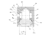
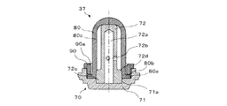
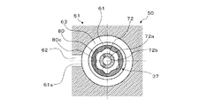
図3は、本発明の実施の形態1に係るブレーキシステムの、ダンパユニットの搭載状態を示す部分断面図である。また、図4は、図3におけるA−A線での断面図である。なお、図3及び図4では、ダンパユニット37以外の部材のみが、断面で示されている。図5及び図6は、本発明の実施の形態1に係るブレーキシステムの、ダンパユニットの詳細を示す断面図である。なお、図5は、図3におけるB−B線での断面図であり、図6は、図5におけるC−C線での断面図である。
<Details of damper unit>
Details of the damper unit of the brake system according to the first embodiment will be described.
FIG. 3 is a partial cross-sectional view showing a mounted state of the damper unit of the brake system according to the first embodiment of the present invention. Further, FIG. 4 is a cross-sectional view taken along the line AA in FIG. In addition, in FIGS. 3 and 4, only the members other than the damper unit 37 are shown in cross section. 5 and 6 are cross-sectional views showing the details of the damper unit of the brake system according to the first embodiment of the present invention. 5 is a cross-sectional view taken along the line BB in FIG. 3, and FIG. 6 is a cross-sectional view taken along the line CC in FIG.

図3及び図4に示されるように、基体51には、収容室61が形成されている。収容室61は、基体51の外壁に形成されている有底穴である。また、基体51には、収容室61とポンプ34の吸込側との間を連通させる内部流路62が形成されている。内部流路62は、連通口61aを介して収容室61に連通する。この内部流路62は、供給流路15の一部を構成するものである。つまり、収容室61には、ブレーキ液が流入する。なお、連通口61aは、収容室61の側部に形成されていてもよく、また、底部に形成されていてもよい。 As shown in FIGS. 3 and 4, a storage chamber 61 is formed in the base 51. The storage chamber 61 is a bottomed hole formed in the outer wall of the base 51. Further, the substrate 51 is formed with an internal flow path 62 that communicates between the accommodating chamber 61 and the suction side of the pump 34. The internal flow path 62 communicates with the accommodating chamber 61 via the communication port 61a. The internal flow path 62 constitutes a part of the supply flow path 15. That is, the brake fluid flows into the accommodation chamber 61. The communication port 61a may be formed on the side portion of the accommodation chamber 61, or may be formed on the bottom portion.

例えば図1の場合、供給流路15は、第2切換弁36と下流側端部との間において分岐している。そして、この分岐している流路の1つがダンパユニット37に接続されている。図1の位置にダンパユニット37を設ける場合、ダンパユニット37に接続されているこの分岐した流路部分の少なくとも一部が、内部流路62となる。すなわち、図1の位置にダンパユニット37を設ける場合、収容室61は、ポンプ34の吸込側に加えて、第2切換弁36にも連通する。また、図2の場合、供給流路15は、上流側端部と第2切換弁36との間において分岐している。そして、この分岐している流路の1つがダンパユニット37に接続されている。図2の位置にダンパユニット37を設ける場合、ダンパユニット37に接続されているこの分岐した流路部分の少なくとも一部が、内部流路62となる。すなわち、図2の位置にダンパユニット37を設ける場合、収容室61は、ポンプ34の吸込側に加えて、マスタシリンダ11にも連通する。なお、図2の位置にダンパユニット37を設ける場合、収容室61は、第2切換弁36を介してポンプ34の吸込側に連通する。 For example, in the case of FIG. 1, the supply flow path 15 is branched between the second switching valve 36 and the downstream end portion. Then, one of the branched flow paths is connected to the damper unit 37. When the damper unit 37 is provided at the position shown in FIG. 1, at least a part of the branched flow path portion connected to the damper unit 37 becomes an internal flow path 62. That is, when the damper unit 37 is provided at the position shown in FIG. 1, the accommodating chamber 61 communicates with the second switching valve 36 in addition to the suction side of the pump 34. Further, in the case of FIG. 2, the supply flow path 15 is branched between the upstream end portion and the second switching valve 36. Then, one of the branched flow paths is connected to the damper unit 37. When the damper unit 37 is provided at the position shown in FIG. 2, at least a part of the branched flow path portion connected to the damper unit 37 becomes an internal flow path 62. That is, when the damper unit 37 is provided at the position shown in FIG. 2, the accommodation chamber 61 communicates with the master cylinder 11 in addition to the suction side of the pump 34. When the damper unit 37 is provided at the position shown in FIG. 2, the accommodating chamber 61 communicates with the suction side of the pump 34 via the second switching valve 36.

また、基体51は、収容室61の内面に形成された凹部63を備えている。そして、収容室61と内部流路62とを連通させる連通口61aは、凹部63の底部に形成されている。詳しくは、本実施の形態1においては、凹部63は、収容室61の側部の内面全周に渡って、環状に形成されている。このような形状の凹部63においては、収容室61を基体51に形成した際、該収容室61の開口部から中ぐりバイトを挿入し、収容室61の側部の内面を中ぐり加工することで形成できる。このため、凹部63の加工が容易になる。換言すると、基体51の製造コストを削減することができる。なお、凹部63の形状は、このような形状に限定されるものではない。連通口61aの位置を収容室61の内面よりも凹んだ位置に形成できれば、凹部63の形状は任意である。例えば、凹部63は、収容室61の軸線(図3において上下方向に延びる中心線)方向に沿って形成された溝でもよい。 Further, the base 51 is provided with a recess 63 formed on the inner surface of the storage chamber 61. A communication port 61a for communicating the accommodating chamber 61 and the internal flow path 62 is formed at the bottom of the recess 63. Specifically, in the first embodiment, the recess 63 is formed in an annular shape over the entire inner surface of the side portion of the storage chamber 61. In the recess 63 having such a shape, when the accommodation chamber 61 is formed on the base 51, a boring tool is inserted through the opening of the accommodation chamber 61, and the inner surface of the side portion of the accommodation chamber 61 is bored. Can be formed with. Therefore, the recess 63 can be easily machined. In other words, the manufacturing cost of the substrate 51 can be reduced. The shape of the recess 63 is not limited to such a shape. The shape of the recess 63 is arbitrary as long as the position of the communication port 61a can be formed at a position recessed from the inner surface of the accommodation chamber 61. For example, the recess 63 may be a groove formed along the axis (center line extending in the vertical direction in FIG. 3) of the accommodation chamber 61.

ダンパユニット37は、収容室61に収容される。ダンパユニット37は、収容室61に収容された状態で後述の基部71等が基体51に加締められて保持されることにより、基体51に固定される。加締めによって、収容室61内のブレーキ液が封止される。なお、ダンパユニット37の基体51への加締め構成の詳細については、後述する。 The damper unit 37 is housed in the storage room 61. The damper unit 37 is fixed to the base 51 by being crimped and held by the base 51 and the like, which will be described later, in a state of being housed in the storage chamber 61. By crimping, the brake fluid in the accommodation chamber 61 is sealed. The details of the crimping configuration of the damper unit 37 to the substrate 51 will be described later.

図5及び図6に示されるように、ダンパユニット37は、柱状体70と、ドーム状膜体80と、環状体90と、を備えている。 As shown in FIGS. 5 and 6, the damper unit 37 includes a columnar body 70, a dome-shaped film body 80, and an annular body 90.

柱状体70は、基体51に保持されている基部71と、基部71に立設されているポール部72と、を有する。基部71及びポール部72は、別部材である。基部71の凹部71aにポール部72の底部が圧入されることで、基部71及びポール部72は、一体化される。ポール部72は、断面が円形状である。ポール部72の底面に有底穴が形成されており、基部71及びポール部72の一体化によってその有底穴が塞がれることとなって、ポール部72の内部に空間72aが形成される。また、ポール部72の側部には、空間72aに通じる貫通穴72bが形成されている。貫通穴72bは、複数(例えば3つ)であり、ポール部72の軸線を基準とする互いに異なる周方向に、等しい角度間隔で形成されている。 The columnar body 70 has a base portion 71 held by the base 51 and a pole portion 72 erected on the base portion 71. The base portion 71 and the pole portion 72 are separate members. By press-fitting the bottom portion of the pole portion 72 into the recess 71a of the base portion 71, the base portion 71 and the pole portion 72 are integrated. The pole portion 72 has a circular cross section. A bottomed hole is formed on the bottom surface of the pole portion 72, and the bottomed hole is closed by integrating the base portion 71 and the pole portion 72, so that a space 72a is formed inside the pole portion 72. .. Further, a through hole 72b leading to the space 72a is formed on the side portion of the pole portion 72. There are a plurality of (for example, three) through holes 72b, and they are formed at equal angular intervals in different circumferential directions with respect to the axis of the pole portion 72.

ドーム状膜体80は、弾性体(例えばゴム等)で形成され、先端部に向かって徐々に細くなる形状である。特に、先端部が球状であることで、収容室61に流入するブレーキ液によって生じる応力集中が抑制される。ドーム状膜体80は、ポール部72の先端部及び側部を覆う状態で保持される。ドーム状膜体80の底部に、外側に突出するフランジ部80aが形成されている。フランジ部80aを介在させた状態で、環状体90が基部71に圧入されることで、ドーム状膜体80は、柱状体70に保持される。すなわち、環状体90は、ドーム状膜体80のフランジ部80aを押圧しつつ、基部71に固定されている。ドーム状膜体80の内側には、流体(例えば空気等)が充填されている。フランジ部80aの環状体90と当接する面には、環状凸部80bが形成されており、環状体90の基部71への圧入に伴って環状凸部80bが押し潰されることによって、収容室61のブレーキ液がドーム状膜体80の内側に流入すること、及び、ドーム状膜体80の内側の流体が収容室61に流出することが抑制される。 The dome-shaped film body 80 is formed of an elastic body (for example, rubber or the like) and has a shape that gradually narrows toward the tip portion. In particular, since the tip portion is spherical, stress concentration caused by the brake fluid flowing into the accommodation chamber 61 is suppressed. The dome-shaped film body 80 is held so as to cover the tip end portion and the side portion of the pole portion 72. A flange portion 80a projecting outward is formed at the bottom of the dome-shaped film body 80. The dome-shaped film body 80 is held by the columnar body 70 by press-fitting the annular body 90 into the base portion 71 with the flange portion 80a interposed therebetween. That is, the annular body 90 is fixed to the base portion 71 while pressing the flange portion 80a of the dome-shaped film body 80. The inside of the dome-shaped film body 80 is filled with a fluid (for example, air). An annular convex portion 80b is formed on the surface of the flange portion 80a that comes into contact with the annular body 90, and the annular convex portion 80b is crushed as the annular body 90 is press-fitted into the base 71, whereby the accommodation chamber 61 The brake fluid is prevented from flowing into the dome-shaped film body 80, and the fluid inside the dome-shaped film body 80 is prevented from flowing out into the accommodation chamber 61.

収容室61にブレーキ液が充填されていない状態において、ドーム状膜体80の内面とポール部72の側部との間には、隙間が形成されている。また、収容室61にブレーキ液が充填されていない状態において、ドーム状膜体80の先端部の内面は、ポール部72の先端部の端面に当接する。ドーム状膜体80の先端部の内面及びポール部72の先端部の端面の互いに当接する領域は、平坦である。 When the accommodation chamber 61 is not filled with the brake fluid, a gap is formed between the inner surface of the dome-shaped film body 80 and the side portion of the pole portion 72. Further, in a state where the accommodation chamber 61 is not filled with the brake fluid, the inner surface of the tip end portion of the dome-shaped film body 80 comes into contact with the end surface of the tip end portion of the pole portion 72. The regions where the inner surface of the tip of the dome-shaped film body 80 and the end face of the tip of the pole 72 abut each other are flat.

貫通穴72bは、ポール部72の軸線方向において、連通口61aと比較して基部71に近い側に形成されている。また、ドーム状膜体80の内面とポール部72の側部との間の隙間は、ポール部72の先端部に近づく程狭くなる。そのため、ドーム状膜体80は、収容室61のブレーキ液の液圧の上昇に伴って、先端部に近い領域から先にポール部72の外面に当接することとなり、また、その当接する領域は、貫通穴72bを塞ぐまで徐々に広がっていくこととなる。ドーム状膜体80は、収容室61のブレーキ液の液圧の減少に伴って、変形前の状態に復帰する。このようなドーム状膜体80の動作によって、第2切換弁36が開いた状態でポンプ34が駆動されることで生じる脈動が、供給流路15及びマスタシリンダ11を介して、ブレーキペダル16に伝搬することが抑制される。そして、ドーム状膜体80の変形が最大となった場合でも、ポール部72の内部に形成されている空間72aに圧縮された流体が残存できるため、圧縮された流体がドーム状膜体80を透過して、ダンパユニット37の減衰性能が劣化してしまうことが抑制される。 The through hole 72b is formed in the axial direction of the pole portion 72 on the side closer to the base portion 71 than the communication port 61a. Further, the gap between the inner surface of the dome-shaped film body 80 and the side portion of the pole portion 72 becomes narrower as it approaches the tip portion of the pole portion 72. Therefore, the dome-shaped film body 80 comes into contact with the outer surface of the pole portion 72 first from the region near the tip portion as the hydraulic fluid pressure of the brake fluid in the accommodation chamber 61 rises, and the abutting region is , It will gradually expand until the through hole 72b is closed. The dome-shaped film body 80 returns to the state before deformation as the hydraulic pressure of the brake fluid in the accommodation chamber 61 decreases. By such an operation of the dome-shaped film body 80, the pulsation generated by driving the pump 34 with the second switching valve 36 open is transmitted to the brake pedal 16 via the supply flow path 15 and the master cylinder 11. Propagation is suppressed. Then, even when the deformation of the dome-shaped film body 80 is maximized, the compressed fluid can remain in the space 72a formed inside the pole portion 72, so that the compressed fluid causes the dome-shaped film body 80 to remain. It is suppressed that the damping performance of the damper unit 37 is deteriorated due to the transmission.

ポール部72の基部71に近い側の端部の外周面には、ドーム状膜体80の内面を受ける環状凸部72cが形成されている。環状凸部72cの基部71から遠い側の端部の外側エッジ72dは、丸められた形状である。また、環状体90の基部71から遠い側の端部の内側エッジ90aは、丸められた形状である。 An annular convex portion 72c that receives the inner surface of the dome-shaped film body 80 is formed on the outer peripheral surface of the end portion of the pole portion 72 near the base portion 71. The outer edge 72d of the end of the annular convex portion 72c on the side farther from the base portion 71 has a rounded shape. Further, the inner edge 90a of the end portion of the annular body 90 on the side far from the base portion 71 has a rounded shape.

上述のように、ダンパユニット37は、収容室61に収容された状態で後述の基部71等が基体51に加締められて保持されることにより、基体51に固定されている。この際、本実施の形態1では、図3に示すような加締め構成を採用している。詳しくは、基体51は、収容室61の内面に、環状体90と対向する環状の台座部64を備えている。この台座部64は、収容室61の内面に形成された凹部63よりも、収容室61の開口部側に配置されている。換言すると、台座部64は、凹部63よりも、収容室61の開口部外縁61c側に配置されている。また、凹部63の底部と収容室61の軸線(図3において上下方向に延びる中心線)との間の距離L1は、台座部64と収容室61の軸線との間の距離L2よりも大きくなっている。換言すると、本実施の形態1においては、凹部63は、収容室61の側部の内面全周に渡って、環状に形成されている。このため、収容室61の軸線を中心として形成された凹部63の底部の半径が、収容室61の軸線を中心として形成された台座部64の半径よりも大きいということもできる。 As described above, the damper unit 37 is fixed to the base 51 by being held in the storage chamber 61 by the base 71 and the like, which will be described later, being crimped to the base 51. At this time, in the first embodiment, the crimping configuration as shown in FIG. 3 is adopted. Specifically, the base 51 is provided with an annular pedestal portion 64 facing the annular body 90 on the inner surface of the accommodation chamber 61. The pedestal portion 64 is arranged closer to the opening side of the accommodation chamber 61 than the recess 63 formed on the inner surface of the accommodation chamber 61. In other words, the pedestal portion 64 is arranged closer to the outer edge 61c of the opening of the accommodation chamber 61 than the recess 63. Further, the distance L1 between the bottom of the recess 63 and the axis of the accommodation chamber 61 (the center line extending in the vertical direction in FIG. 3) is larger than the distance L2 between the pedestal portion 64 and the axis of the accommodation chamber 61. ing. In other words, in the first embodiment, the recess 63 is formed in an annular shape over the entire inner surface of the side portion of the storage chamber 61. Therefore, it can be said that the radius of the bottom of the recess 63 formed around the axis of the accommodation chamber 61 is larger than the radius of the pedestal portion 64 formed around the axis of the accommodation chamber 61.

そして、ダンパユニット37は、図6のように組み付けられた基部71、ドーム状膜体80のフランジ部80a及び環状体90が台座部64と収容室61の開口部外縁61cとで挟持されることにより、基体51に加締め固定される。ダンパユニット37が基体51に加締め固定されることにより、ダンパユニット37の基部71及び環状体90の外周面と、台座部64の環状体90と対向する領域及び収容室61の内面のうちの基部71及び環状体90の外周面と対向する領域61bと、が密着して、収容室61内のブレーキ液が封止される。 Then, in the damper unit 37, the base portion 71, the flange portion 80a of the dome-shaped film body 80, and the annular body 90 assembled as shown in FIG. 6 are sandwiched between the pedestal portion 64 and the outer edge 61c of the opening of the accommodation chamber 61. Is crimped and fixed to the substrate 51. By crimping and fixing the damper unit 37 to the base 51, the outer peripheral surface of the base 71 and the annular body 90 of the damper unit 37, the area of the pedestal portion 64 facing the annular body 90, and the inner surface of the accommodation chamber 61. The base 71 and the region 61b facing the outer peripheral surface of the annular body 90 are in close contact with each other, and the brake fluid in the accommodation chamber 61 is sealed.

<ブレーキシステムの効果>
実施の形態1に係るブレーキシステムの効果について説明する。
ブレーキシステム1の液圧制御ユニット50では、供給流路15にダンパユニット37が設けられている。そのため、第2切換弁36が開いた状態でポンプ34が駆動されることで生じる脈動が、供給流路15及びマスタシリンダ11を介して、ブレーキシステム1の入力部(例えばブレーキペダル16等)に伝搬することが抑制される。
<Effect of braking system>
The effect of the brake system according to the first embodiment will be described.
In the hydraulic pressure control unit 50 of the brake system 1, a damper unit 37 is provided in the supply flow path 15. Therefore, the pulsation generated by driving the pump 34 with the second switching valve 36 open is transmitted to the input unit (for example, the brake pedal 16) of the brake system 1 via the supply flow path 15 and the master cylinder 11. Propagation is suppressed.

特に、ブレーキシステム1の液圧制御ユニット50が、込め弁31が開き、弛め弁32が閉じ、第1切換弁35が閉じ、第2切換弁36が開き、且つ、ブレーキシステム1の入力部にブレーキ操作が入力されている状態で、ポンプ34を駆動させる、アクティブ増圧制御動作を行うものである場合において、ダンパユニット37が供給流路15に設けられている場合には、使用者のブレーキシステム1の使用感を確保しつつ、倍力装置17を小型化又は省略して、ブレーキシステム1の車両100への搭載性を向上することが可能である。 In particular, the hydraulic pressure control unit 50 of the brake system 1 opens the filling valve 31, closes the loosening valve 32, closes the first switching valve 35, opens the second switching valve 36, and opens the input unit of the brake system 1. When the damper unit 37 is provided in the supply flow path 15 in the case where the active pressure boosting control operation for driving the pump 34 is performed with the brake operation input to, the user's It is possible to improve the mountability of the brake system 1 on the vehicle 100 by downsizing or omitting the booster 17 while ensuring the usability of the brake system 1.

ダンパユニット37は、供給流路15のうちの、第2切換弁36と下流側端部との間の領域に設けられていてもよく、また、供給流路15のうちの、上流側端部と第2切換弁36との間の領域に設けられていてもよい。 The damper unit 37 may be provided in the region of the supply flow path 15 between the second switching valve 36 and the downstream end portion, and the upstream end portion of the supply flow path 15 may be provided. It may be provided in the area between the second switching valve 36 and the second switching valve 36.

例えば、供給流路15のうちの、第2切換弁36と下流側端部との間の領域に、ダンパユニット37が設けられている場合には、ポンプ34の吸入側の近くで、脈動の伝搬が抑制されることとなって、液圧制御ユニット50の基体51等に生じる異音等を効率的に抑制することができる。 For example, when the damper unit 37 is provided in the region of the supply flow path 15 between the second switching valve 36 and the downstream end, the pulsation of the pulsation is near the suction side of the pump 34. Since the propagation is suppressed, abnormal noise or the like generated on the substrate 51 or the like of the hydraulic pressure control unit 50 can be efficiently suppressed.

例えば、ブレーキシステム1が、倍力装置17が省略されているものであり、且つ、供給流路15のうちの、上流側端部と第2切換弁36との間の領域に、ダンパユニット37が設けられている場合には、使用者がブレーキシステム1の入力部を操作してからアクティブ増圧制御動作が開始されるまでの期間において、使用者が、倍力装置17が省略されていることに起因する反力の増大を感じてしまうことが、ダンパユニット37のクッション性によって抑制されることとなる。そのため、供給流路15のうちの、上流側端部と第2切換弁36との間の領域にダンパユニット37を設けることは、ブレーキシステム1が、倍力装置17が省略されているものである場合において、特に好適である。 For example, in the brake system 1, the booster 17 is omitted, and the damper unit 37 is located in the region of the supply flow path 15 between the upstream end and the second switching valve 36. When is provided, the booster 17 is omitted by the user during the period from the operation of the input unit of the brake system 1 to the start of the active boost control operation. The increase in reaction force caused by this is suppressed by the cushioning property of the damper unit 37. Therefore, the damper unit 37 is provided in the region between the upstream end and the second switching valve 36 in the supply flow path 15, because the brake system 1 omits the booster 17. In some cases, it is particularly suitable.

そして、ブレーキシステム1の液圧制御ユニット50では、更に、ダンパユニット37が、ポール部72を有する柱状体70と、ドーム状膜体80と、を備えており、収容室61にブレーキ液が充填されていない状態で、ドーム状膜体80の内面とポール部72の側部の少なくとも一部との間に隙間が形成されている構成である。ダンパユニット37は、マスタシリンダ11に連通する供給流路15、つまり、使用者のブレーキシステム1の使用感に多大な影響を及ぼす箇所に設けられるものであり、高い減衰性能を有することが望まれる。一方、液圧制御ユニット50が車両100に搭載される場合には、そのサイズも重要視される。ダンパユニット37は、受圧面の面積が三次元的に拡大される構造であるため、減衰性能の向上に伴う液圧制御ユニット50の大型化が効率的に抑制される。すなわち、ダンパユニット37は、ブレーキシステム1の供給流路15に設けられることが、特に好適なものであり、そのようなダンパユニット37の採用によって、使用者のブレーキシステム1の使用感を向上することの実現性が格段向上される。 Further, in the hydraulic pressure control unit 50 of the brake system 1, the damper unit 37 further includes a columnar body 70 having a pole portion 72 and a dome-shaped film body 80, and the accommodation chamber 61 is filled with the brake fluid. In this state, a gap is formed between the inner surface of the dome-shaped film body 80 and at least a part of the side portion of the pole portion 72. The damper unit 37 is provided in a supply flow path 15 communicating with the master cylinder 11, that is, a position that greatly affects the usability of the user's brake system 1, and is desired to have high damping performance. .. On the other hand, when the hydraulic pressure control unit 50 is mounted on the vehicle 100, its size is also important. Since the damper unit 37 has a structure in which the area of the pressure receiving surface is three-dimensionally expanded, the increase in size of the hydraulic pressure control unit 50 due to the improvement in damping performance is efficiently suppressed. That is, it is particularly preferable that the damper unit 37 is provided in the supply flow path 15 of the brake system 1, and by adopting such a damper unit 37, the usability of the brake system 1 of the user is improved. The feasibility of things is greatly improved.

ここで、ダンパユニット37は、ドーム状膜体80の外面側の圧力(つまり収容室61内のブレーキ液の液圧)と内面側の圧力との圧力差によって該ドーム状膜体80が変形し、ポンプ34の駆動時に発生する脈動を減衰する構成となっている。このため、ダンパユニット37は、ドーム状膜体80の外面側の圧力が内面側の圧力よりも低下し、図7に示すようにドーム状膜体80が外面側に膨張するように変形する場合がある。
なお、図7は、本発明の実施の形態1に係るブレーキシステムの、ダンパユニットの搭載状態を示す部分断面図であり、ドーム状膜体が外面側に膨張するように変形した状態を示す図である。この図7は、図3と同じ方向からダンパユニット37の搭載状態を観察した図であり、図3と同様にダンパユニット37以外の部材のみが断面で示されている。
Here, in the damper unit 37, the dome-shaped film body 80 is deformed by the pressure difference between the pressure on the outer surface side of the dome-shaped film body 80 (that is, the hydraulic pressure of the brake fluid in the accommodation chamber 61) and the pressure on the inner surface side. , The pulsation generated when the pump 34 is driven is dampened. Therefore, in the damper unit 37, when the pressure on the outer surface side of the dome-shaped film body 80 is lower than the pressure on the inner surface side, the dome-shaped film body 80 is deformed so as to expand toward the outer surface side as shown in FIG. There is.
Note that FIG. 7 is a partial cross-sectional view showing a mounted state of the damper unit of the brake system according to the first embodiment of the present invention, showing a state in which the dome-shaped film body is deformed so as to expand toward the outer surface side. Is. FIG. 7 is a view of observing the mounted state of the damper unit 37 from the same direction as in FIG. 3, and as in FIG. 3, only the members other than the damper unit 37 are shown in cross section.

例えば、ブレーキシステム1の液圧制御ユニット50が、込め弁31が開き、弛め弁32が閉じ、第1切換弁35が閉じ、第2切換弁36が開き、且つ、ブレーキシステム1の入力部にブレーキ操作が入力されている状態で、ポンプ34を駆動させる、アクティブ増圧制御動作を行うとする。この場合、ポンプ34の起動直後において、ダンパユニット37が収容されている収容室61からポンプ34によって吸引されるブレーキ液の量が、収容室61に流入するブレーキ液の量を一時的に上回ることがある。このとき、ドーム状膜体80の外面側の圧力が内面側の圧力よりも一時的に低下し、ドーム状膜体80が外面側に膨張するように変形する。 For example, the hydraulic pressure control unit 50 of the brake system 1 opens the filling valve 31, closes the loosening valve 32, closes the first switching valve 35, opens the second switching valve 36, and opens the input unit of the brake system 1. It is assumed that an active boost control operation for driving the pump 34 is performed while the brake operation is input to. In this case, immediately after the pump 34 is started, the amount of brake fluid sucked by the pump 34 from the accommodation chamber 61 in which the damper unit 37 is accommodated temporarily exceeds the amount of brake fluid flowing into the accommodation chamber 61. There is. At this time, the pressure on the outer surface side of the dome-shaped film body 80 is temporarily lower than the pressure on the inner surface side, and the dome-shaped film body 80 is deformed so as to expand toward the outer surface side.

また例えば、ブレーキシステム1の液圧制御ユニット50が、車輪がロックすることを防止するため、込め弁31が閉じ、弛め弁32が開き、第1切換弁35が開き、第2切換弁36が閉じ、且つ、ブレーキシステム1の入力部にブレーキ操作が入力されている状態で、ポンプ34を駆動させる制御動作を行うとする。この場合、図1の位置にダンパユニット37を設けたブレーキシステム1の液圧制御ユニット50においては、ポンプ34の起動直後、ダンパユニット37が収容されている収容室61からポンプ34によって吸引されるブレーキ液の量が、収容室61に流入するブレーキ液の量を一時的に上回ることがある。このとき、ドーム状膜体80の外面側の圧力が内面側の圧力よりも一時的に低下し、ドーム状膜体80が外面側に膨張するように変形する。 Further, for example, in order to prevent the hydraulic pressure control unit 50 of the brake system 1 from locking the wheels, the filling valve 31 is closed, the loosening valve 32 is opened, the first switching valve 35 is opened, and the second switching valve 36 is opened. Is closed and the brake operation is input to the input unit of the brake system 1, and the control operation for driving the pump 34 is performed. In this case, in the hydraulic pressure control unit 50 of the brake system 1 provided with the damper unit 37 at the position shown in FIG. 1, the pump 34 sucks the brake unit 37 from the accommodation chamber 61 in which the damper unit 37 is housed immediately after the pump 34 is started. The amount of brake fluid may temporarily exceed the amount of brake fluid flowing into the containment chamber 61. At this time, the pressure on the outer surface side of the dome-shaped film body 80 is temporarily lower than the pressure on the inner surface side, and the dome-shaped film body 80 is deformed so as to expand toward the outer surface side.

また例えば、ブレーキシステム1の入力部への入力が解除された際(例えば、使用者がブレーキペダル16の踏み込みを解除した際)、ブレーキ液がマスタシリンダ11に引き込まれる。この際、図2の位置にダンパユニット37を設けたブレーキシステム1の液圧制御ユニット50においては、マスタシリンダ11のブレーキ液の引き込みによって収容室61から吸引されるブレーキ液の量が、収容室61に流入するブレーキ液の量を一時的に上回ることがある。このとき、ドーム状膜体80の外面側の圧力が内面側の圧力よりも一時的に低下し、ドーム状膜体80が外面側に膨張するように変形する。 Further, for example, when the input to the input unit of the brake system 1 is released (for example, when the user releases the depression of the brake pedal 16), the brake fluid is drawn into the master cylinder 11. At this time, in the hydraulic pressure control unit 50 of the brake system 1 provided with the damper unit 37 at the position shown in FIG. 2, the amount of brake fluid sucked from the accommodation chamber 61 by drawing in the brake fluid of the master cylinder 11 is the amount of the brake fluid sucked from the accommodation chamber 61. It may temporarily exceed the amount of brake fluid flowing into 61. At this time, the pressure on the outer surface side of the dome-shaped film body 80 is temporarily lower than the pressure on the inner surface side, and the dome-shaped film body 80 is deformed so as to expand toward the outer surface side.

また例えば、ブレーキシステム1(換言すると液圧制御ユニット50)にブレーキ液を充填する際、主流路13、副流路14及び供給流路15に空気が残ることを防止するため、これらの流路を真空状態(大気圧よりも低い状態)にし、真空状態となったこれらの流路にブレーキ液を流し込む手法を採用する場合がある。このような場合、供給流路15が真空状態になったときに、ドーム状膜体80の外面側の圧力が内面側の圧力よりも低下し、ドーム状膜体80が外面側に膨張するように変形する。また例えば、ブレーキシステム1(換言すると液圧制御ユニット50)は、広い温度範囲での使用を想定して設計される。このため、ブレーキシステム1(換言すると液圧制御ユニット50)周辺の温度が使用温度範囲のうちの上限温度付近となった場合、ドーム状膜体80の熱膨張によって、ドーム状膜体80が外面側に膨張するように変形することもある。 Further, for example, when the brake system 1 (in other words, the hydraulic pressure control unit 50) is filled with the brake fluid, these flow paths are prevented from remaining in the main flow path 13, the sub flow path 14, and the supply flow path 15. Is put into a vacuum state (a state lower than the atmospheric pressure), and a method of pouring the brake fluid into these vacuum flow paths may be adopted. In such a case, when the supply flow path 15 is in a vacuum state, the pressure on the outer surface side of the dome-shaped film body 80 becomes lower than the pressure on the inner surface side, and the dome-shaped film body 80 expands toward the outer surface side. Transforms into. Further, for example, the brake system 1 (in other words, the hydraulic pressure control unit 50) is designed assuming use in a wide temperature range. Therefore, when the temperature around the brake system 1 (in other words, the hydraulic pressure control unit 50) becomes close to the upper limit temperature within the operating temperature range, the dome-shaped film body 80 is exposed to the outer surface due to the thermal expansion of the dome-shaped film body 80. It may be deformed to expand to the side.

上述のようにドーム状膜体80が外面側に膨張するように変形した場合、ドーム状膜体80が連通口61aに接触し、連通口61aを閉塞して供給流路15(換言すると液圧回路2)内のブレーキ液の流れを阻害してしまう、ドーム状膜体80が損傷してしまう等を懸念するかもしれない。しかしながら、本実施の形態1に係る液圧制御ユニット50においては、収容室61の内面に形成された凹部63を備え、該凹部63の底部に連通口61aが形成されている。このため、本実施の形態1に係る液圧制御ユニット50は、ドーム状膜体80が外面側に膨張するように変形した場合でも、図7に示すように、ドーム状膜体80が連通口61aに接触することを抑制できる。すなわち、本実施の形態1に係る液圧制御ユニット50は、ドーム状膜体80が外面側に膨張するように変形した場合でも、連通口61aを閉塞して供給流路15(換言すると液圧回路2)内のブレーキ液の流れを阻害してしまう、ドーム状膜体80が損傷してしまう等を抑制できる。 When the dome-shaped film body 80 is deformed so as to expand to the outer surface side as described above, the dome-shaped film body 80 comes into contact with the communication port 61a, closes the communication port 61a, and the supply flow path 15 (in other words, hydraulic pressure). There may be concerns that the flow of brake fluid in the circuit 2) is obstructed, the dome-shaped membrane 80 is damaged, and the like. However, the hydraulic pressure control unit 50 according to the first embodiment includes a recess 63 formed on the inner surface of the accommodating chamber 61, and a communication port 61a is formed at the bottom of the recess 63. Therefore, in the hydraulic pressure control unit 50 according to the first embodiment, even when the dome-shaped membrane 80 is deformed so as to expand to the outer surface side, the dome-shaped membrane 80 communicates with the dome-shaped membrane 80 as shown in FIG. Contact with 61a can be suppressed. That is, the hydraulic pressure control unit 50 according to the first embodiment closes the communication port 61a and the supply flow path 15 (in other words, the hydraulic pressure) even when the dome-shaped membrane body 80 is deformed so as to expand toward the outer surface side. It is possible to prevent the flow of the brake fluid in the circuit 2) from being obstructed, the dome-shaped film body 80 from being damaged, and the like.

好ましくは、凹部63は、収容室61の側部の内面全周に渡って、環状に形成されている。このように凹部63を形成することにより、凹部63の加工が容易となり、基体51の製造コストを削減することができる。 Preferably, the recess 63 is formed in an annular shape over the entire inner surface of the side portion of the storage chamber 61. By forming the recess 63 in this way, the recess 63 can be easily processed, and the manufacturing cost of the substrate 51 can be reduced.

好ましくは、ブレーキシステム1の液圧制御ユニット50では、収容室61にブレーキ液が充填されていない状態で、ドーム状膜体80の先端部の内面は、ポール部72の先端部の外面の少なくとも一部に当接する。そのように構成されることで、収容室61のブレーキ液の液圧の変化に伴うドーム状膜体80の変形及び復帰が、安定化されることとなって、第2切換弁36が開いた状態でポンプ34が駆動されることで生じる脈動が、供給流路15及びマスタシリンダ11を介して、ブレーキシステム1の入力部に伝搬することの抑制が、確実化される。 Preferably, in the hydraulic pressure control unit 50 of the brake system 1, the inner surface of the tip end portion of the dome-shaped film body 80 is at least the outer surface of the tip end portion of the pole portion 72 in a state where the accommodation chamber 61 is not filled with the brake fluid. Contact a part. With such a configuration, the deformation and restoration of the dome-shaped film body 80 due to the change in the hydraulic pressure of the brake fluid in the accommodation chamber 61 are stabilized, and the second switching valve 36 is opened. Suppression that the pulsation generated by driving the pump 34 in the state propagates to the input portion of the brake system 1 via the supply flow path 15 and the master cylinder 11 is ensured.

更に、ドーム状膜体80の先端部及びポール部72の先端部の互いに当接する領域が、平坦であるとよい。そのように構成されることで、例えば、環状体90を基部71に圧入する等の組立作業に際して、ドーム状膜体80を位置決めすることが可能となって、組立性が向上される。また、ドーム状膜体80が損傷したまま組み付けられることが抑制されて、液圧制御ユニット50が高品質化される。 Further, it is preferable that the abutting region of the tip portion of the dome-shaped film body 80 and the tip portion of the pole portion 72 is flat. With such a configuration, the dome-shaped film body 80 can be positioned at the time of assembling work such as press-fitting the annular body 90 into the base 71, and the assembling property is improved. Further, it is suppressed that the dome-shaped film body 80 is assembled while being damaged, and the quality of the hydraulic pressure control unit 50 is improved.

更に、ポール部72の軸線方向において、貫通穴72bは、収容室61のポンプ34に連通する連通口61aと比較して、基部71に近い側に形成されているとよい。そのように構成されることで、収容室61のブレーキ液の液圧の上昇の際に、ドーム状膜体80が、早い段階で貫通穴72bを塞いで、ダンパユニット37の減衰性能が低下してしまうことが抑制される。 Further, in the axial direction of the pole portion 72, the through hole 72b may be formed on the side closer to the base portion 71 as compared with the communication port 61a communicating with the pump 34 of the accommodation chamber 61. With such a configuration, when the hydraulic pressure of the brake fluid in the accommodation chamber 61 rises, the dome-shaped film body 80 closes the through hole 72b at an early stage, and the damping performance of the damper unit 37 deteriorates. It is suppressed.

好ましくは、ブレーキシステム1の液圧制御ユニット50では、貫通穴72bは複数であり、複数の貫通穴72bは、ポール部72の軸線を基準とする互いに異なる周方向に形成されている。そのように構成されることで、ポール部72の1方向に応力集中が生じてしまうことが抑制されて、ダンパユニット37の耐久性が向上される。 Preferably, in the hydraulic pressure control unit 50 of the brake system 1, there are a plurality of through holes 72b, and the plurality of through holes 72b are formed in different circumferential directions with respect to the axis of the pole portion 72. With such a configuration, stress concentration is suppressed in one direction of the pole portion 72, and the durability of the damper unit 37 is improved.

好ましくは、ブレーキシステム1の液圧制御ユニット50では、ドーム状膜体80の底部にフランジ部80aが形成され、ダンパユニット37は、更に、フランジ部80aを押圧しつつ基部71に固定されている環状体90を備えている。そのように構成されることで、ドーム状膜体80の損傷を抑制しつつ、ドーム状膜体80を柱状体70に組付けることが可能となって、ダンパユニット37の耐久性が向上される。 Preferably, in the hydraulic pressure control unit 50 of the brake system 1, a flange portion 80a is formed at the bottom of the dome-shaped film body 80, and the damper unit 37 is further fixed to the base portion 71 while pressing the flange portion 80a. It includes an annular body 90. With such a configuration, it becomes possible to assemble the dome-shaped film body 80 to the columnar body 70 while suppressing damage to the dome-shaped film body 80, and the durability of the damper unit 37 is improved. ..

更に、フランジ部80aの環状体90と当接する面に、環状凸部80bが形成されているとよい。そのように構成されることで、収容室61のブレーキ液がドーム状膜体80の内側に流入すること、及び、ドーム状膜体80の内側の流体が収容室61に流出することの抑制を、簡易な構成で確実化することができる。 Further, it is preferable that the annular convex portion 80b is formed on the surface of the flange portion 80a that comes into contact with the annular body 90. With such a configuration, it is possible to prevent the brake fluid in the accommodation chamber 61 from flowing into the dome-shaped membrane 80 and the fluid inside the dome-shaped membrane 80 from flowing out into the accommodation chamber 61. , Can be ensured with a simple configuration.

更に、環状体90の基部71から遠い側の端部の内側エッジ90aは、丸められた形状である。そのように構成されることで、例えば、ABS制御動作時、ESP制御動作時等において、収容室61のブレーキ液の液圧が減少する際に、ドーム状膜体80の外面が損傷してしまうことが抑制されて、ダンパユニット37の耐久性が向上される。 Further, the inner edge 90a of the end portion of the annular body 90 on the side farther from the base portion 71 has a rounded shape. With such a configuration, for example, during ABS control operation, ESP control operation, etc., the outer surface of the dome-shaped film body 80 is damaged when the hydraulic pressure of the brake fluid in the accommodation chamber 61 decreases. This is suppressed and the durability of the damper unit 37 is improved.

好ましくは、ダンパユニット37が、フランジ部80aを押圧しつつ基部71に固定されている環状体90を備え、基体51に加締め固定される場合、基体51は、収容室61の内面に、環状体90と対向する環状の台座部64を備えている。この台座部64は、収容室61の内面に形成された凹部63よりも、収容室61の開口部外縁61c側に配置されている。また、凹部63の底部と収容室61の軸線(図3において上下方向に延びる中心線)との間の距離L1は、台座部64と収容室61の軸線との間の距離L2よりも大きくなっている。そして、ダンパユニット37は、基部71、ドーム状膜体80のフランジ部80a及び環状体90が台座部64と収容室61の開口部外縁61cとで挟持されることにより、基体51に加締め固定される。 Preferably, when the damper unit 37 includes an annular body 90 fixed to the base 71 while pressing the flange portion 80a and is crimped and fixed to the base 51, the base 51 is annular to the inner surface of the accommodation chamber 61. It is provided with an annular pedestal portion 64 facing the body 90. The pedestal portion 64 is arranged closer to the outer edge 61c of the opening of the accommodation chamber 61 than the recess 63 formed on the inner surface of the accommodation chamber 61. Further, the distance L1 between the bottom of the recess 63 and the axis of the accommodation chamber 61 (the center line extending in the vertical direction in FIG. 3) is larger than the distance L2 between the pedestal portion 64 and the axis of the accommodation chamber 61. ing. The damper unit 37 is crimped and fixed to the base 51 by sandwiching the base 71, the flange portion 80a of the dome-shaped film body 80, and the annular body 90 between the pedestal portion 64 and the outer edge 61c of the opening of the accommodation chamber 61. Will be done.

このような加締め固定においては、収容室61の開口部外縁61cに荷重をかけ、開口部外縁61cを変形させる際、該荷重は、基部71、ドーム状膜体80のフランジ部80a及び環状体90を介して、台座部64で支持される。この際、台座部64における荷重を支持する面積が小さいと、台座部64が塑性変形してしまう。そして、台座部64が塑性変形してしまうと、加締め部分において隙間ができてしまい、収容室61内のブレーキ液が基体51外へ漏れ出してしまう。一方、上述のように台座部64を形成することにより、台座部64における荷重を支持する面積を大きく確保することができるため、台座部64の塑性変形を抑制できる。すなわち、上述のように台座部64を形成することにより、加締め部分において隙間ができてしまうことを抑制でき、収容室61内のブレーキ液が基体51外へ漏れ出してしまうことを抑制できる。 In such crimping and fixing, when a load is applied to the opening outer edge 61c of the accommodating chamber 61 to deform the opening outer edge 61c, the load is applied to the base 71, the flange portion 80a of the dome-shaped film body 80, and the annular body. It is supported by the pedestal portion 64 via the 90. At this time, if the area of the pedestal portion 64 that supports the load is small, the pedestal portion 64 will be plastically deformed. If the pedestal portion 64 is plastically deformed, a gap is formed in the crimped portion, and the brake fluid in the accommodation chamber 61 leaks out of the base 51. On the other hand, by forming the pedestal portion 64 as described above, a large area for supporting the load in the pedestal portion 64 can be secured, so that the plastic deformation of the pedestal portion 64 can be suppressed. That is, by forming the pedestal portion 64 as described above, it is possible to suppress the formation of a gap in the crimping portion and prevent the brake fluid in the accommodation chamber 61 from leaking to the outside of the substrate 51.

好ましくは、ブレーキシステム1の液圧制御ユニット50では、ポール部72の基部71に近い側の端部の外周面に、ドーム状膜体80の内面を受ける環状凸部72cが形成されており、環状凸部72cの基部71から遠い側の端部の外側エッジ72dは、丸められた形状である。環状凸部72cがドーム状膜体80の受け部として機能することとなって、収容室61のブレーキ液の液圧の変化に伴うドーム状膜体80の変形及び復帰が、安定化される。また、環状凸部72cの基部71から遠い側の端部の外側エッジ72dが、丸められた形状であることで、収容室61のブレーキ液の液圧の上昇の際に、ドーム状膜体80の内面が損傷してしまうことが抑制されて、ダンパユニット37の耐久性が向上される。 Preferably, in the hydraulic pressure control unit 50 of the brake system 1, an annular convex portion 72c that receives the inner surface of the dome-shaped film body 80 is formed on the outer peripheral surface of the end portion of the pole portion 72 near the base portion 71. The outer edge 72d of the end of the annular convex portion 72c on the side farther from the base portion 71 has a rounded shape. The annular convex portion 72c functions as a receiving portion of the dome-shaped film body 80, and the deformation and restoration of the dome-shaped film body 80 due to the change in the hydraulic pressure of the brake fluid in the accommodation chamber 61 are stabilized. Further, since the outer edge 72d of the end portion of the annular convex portion 72c on the side far from the base portion 71 has a rounded shape, the dome-shaped film body 80 is formed when the hydraulic pressure of the brake fluid in the accommodation chamber 61 rises. Damage to the inner surface of the damper unit 37 is suppressed, and the durability of the damper unit 37 is improved.

好ましくは、基部71及びポール部72は、別部材であり、ポール部72の底面に、空間72aを構成する有底穴が形成されている。そのように構成されることで、空間72aを有する柱状体70の製造性が向上される。 Preferably, the base portion 71 and the pole portion 72 are separate members, and a bottomed hole forming the space 72a is formed on the bottom surface of the pole portion 72. With such a configuration, the manufacturability of the columnar body 70 having the space 72a is improved.

なお、本実施の形態1では、供給流路15に分岐した流路を形成し、この分岐した流路にダンパユニット37を設けた。しかしながら、ダンパユニット37の設置構成はこのような構成に限定されるものではなく、供給流路15を分岐させずにダンパユニット37を設けてもよい。例えば、図1で示したブレーキシステム1(つまり液圧制御ユニット50)の場合、供給流路15のうち、第2切換弁36と接続されて下流側端部まで延びる流路部分に、直接、ダンパユニット37を設けてもよい。また例えば、図2で示したブレーキシステム1(つまり液圧制御ユニット50)の場合、供給流路15のうち、第2切換弁36と接続されて上流側端部まで延びる流路部分に、直接、ダンパユニット37を設けてもよい。以下、図2に示したブレーキシステム1(つまり液圧制御ユニット50)において、供給流路15を分岐させずにダンパユニット37を設けた例を、図8及び図9を用いて説明する。 In the first embodiment, a branched flow path is formed in the supply flow path 15, and a damper unit 37 is provided in the branched flow path. However, the installation configuration of the damper unit 37 is not limited to such a configuration, and the damper unit 37 may be provided without branching the supply flow path 15. For example, in the case of the brake system 1 (that is, the hydraulic pressure control unit 50) shown in FIG. 1, the flow path portion of the supply flow path 15 that is connected to the second switching valve 36 and extends to the downstream end is directly connected to the flow path portion. The damper unit 37 may be provided. Further, for example, in the case of the brake system 1 (that is, the hydraulic pressure control unit 50) shown in FIG. 2, the supply flow path 15 is directly connected to the second switching valve 36 and extends to the upstream end. , The damper unit 37 may be provided. Hereinafter, in the brake system 1 (that is, the hydraulic pressure control unit 50) shown in FIG. 2, an example in which the damper unit 37 is provided without branching the supply flow path 15 will be described with reference to FIGS. 8 and 9.

図8は、本発明の実施の形態1に係るブレーキシステムの、システム構成の更に別の例を示す図である。また、図9は、図8に示すブレーキシステムの、ダンパユニットの搭載状態を示す部分断面図である。なお、図9では、ダンパユニット37以外の部材のみが、断面で示されている。 FIG. 8 is a diagram showing still another example of the system configuration of the brake system according to the first embodiment of the present invention. Further, FIG. 9 is a partial cross-sectional view showing a mounted state of the damper unit of the brake system shown in FIG. In FIG. 9, only the members other than the damper unit 37 are shown in cross section.

図8に示すブレーキシステム1(つまり液圧制御ユニット50)は、供給流路15のうち、第2切換弁36と接続されて上流側端部まで延びる流路部分に、直接、ダンパユニット37が設けられている。このような場合、供給流路15の一部を構成する内部流路62として、2つの内部流路62a,62bが形成される。内部流路62aは、一端が連通口61aを介して収容室61と連通し、他端が第2切換弁36を介してポンプ34の吸込側に連通している。また、内部流路62bは、一端が連通口61aを介して収容室61と連通し、他端がマスタシリンダ11に連通している。内部流路62として2つの内部流路62a,62bが形成される場合、内部流路62a,62bの一方を通ってブレーキ液が収容室61に流入し、内部流路62a,62bの他方を通って収容室61からブレーキ液が流出することとなる。
ここで、内部流路62a,62bのうち、収容室61にブレーキ液を流入させる流路が、本発明の第1内部流路に相当する。内部流路62a,62bのうち、収容室61からブレーキ液を流出させる流路が、本発明の第2内部流路に相当する。
In the brake system 1 (that is, the hydraulic pressure control unit 50) shown in FIG. 8, the damper unit 37 is directly connected to the flow path portion of the supply flow path 15 which is connected to the second switching valve 36 and extends to the upstream end. It is provided. In such a case, two internal flow paths 62a and 62b are formed as the internal flow paths 62 forming a part of the supply flow path 15. One end of the internal flow path 62a communicates with the accommodating chamber 61 via the communication port 61a, and the other end communicates with the suction side of the pump 34 via the second switching valve 36. Further, one end of the internal flow path 62b communicates with the accommodating chamber 61 via the communication port 61a, and the other end communicates with the master cylinder 11. When two internal flow paths 62a and 62b are formed as the internal flow paths 62, the brake fluid flows into the accommodating chamber 61 through one of the internal flow paths 62a and 62b and passes through the other of the internal flow paths 62a and 62b. The brake fluid will flow out from the accommodation chamber 61.
Here, of the internal flow paths 62a and 62b, the flow path for flowing the brake fluid into the accommodation chamber 61 corresponds to the first internal flow path of the present invention. Of the internal flow paths 62a and 62b, the flow path through which the brake fluid flows out from the accommodation chamber 61 corresponds to the second internal flow path of the present invention.

例えば、アクティブ増圧制御動作等のように、マスタシリンダ11側から第2切換弁36側にブレーキ液が流れる場合、内部流路62bを通ってブレーキ液が収容室61に流入し、内部流路62aを通って収容室61からブレーキ液が流出することとなる。また例えば、ブレーキシステム1の入力部への入力が解除された際(例えば、使用者がブレーキペダル16の踏み込みを解除した際)、マスタシリンダ11のブレーキ液の引き込みによって、第2切換弁36側からマスタシリンダ11側にブレーキ液が流れる。この場合、内部流路62aを通ってブレーキ液が収容室61に流入し、内部流路62bを通って収容室61からブレーキ液が流出することとなる。 For example, when the brake fluid flows from the master cylinder 11 side to the second switching valve 36 side as in the active pressure boost control operation, the brake fluid flows into the accommodating chamber 61 through the internal flow path 62b and flows into the internal flow path. Brake fluid will flow out from the accommodation chamber 61 through 62a. Further, for example, when the input to the input unit of the brake system 1 is released (for example, when the user releases the depression of the brake pedal 16), the brake fluid of the master cylinder 11 is drawn in to the second switching valve 36 side. Brake fluid flows from the master cylinder 11 side. In this case, the brake fluid flows into the accommodating chamber 61 through the internal flow path 62a, and the brake fluid flows out from the accommodating chamber 61 through the internal flow path 62b.

したがって、内部流路62として2つの内部流路62a,62bが形成される場合、ドーム状膜体80が外面側に膨張するように変形した際に、連通口61aを閉塞して供給流路15(換言すると液圧回路2)内のブレーキ液の流れを阻害してしまうことを防止するためには、内部流路62aの連通口61a及び内部流路62bの連通口61aの双方を該凹部63の底部に形成する必要がある。この際、凹部63を、収容室61の側部の内面全周に渡って環状に形成するとよい。内部流路62aの連通口61aが形成される凹部63と内部流路62bの連通口61aが形成される凹部63とを一回の中ぐり加工で形成できるため、基体51の製造コストを削減することができる。 Therefore, when two internal flow paths 62a and 62b are formed as the internal flow paths 62, when the dome-shaped film body 80 is deformed so as to expand toward the outer surface side, the communication port 61a is closed and the supply flow path 15 In order to prevent the flow of the brake fluid in the (hydraulic circuit 2) from being obstructed, both the communication port 61a of the internal flow path 62a and the communication port 61a of the internal flow path 62b are made into the recess 63. Must be formed at the bottom of the. At this time, the recess 63 may be formed in an annular shape over the entire inner surface of the side portion of the storage chamber 61. Since the recess 63 in which the communication port 61a of the internal flow path 62a is formed and the recess 63 in which the communication port 61a of the internal flow path 62b is formed can be formed by a single boring process, the manufacturing cost of the substrate 51 can be reduced. be able to.

以上のように供給流路15を分岐させずにダンパユニット37を設けた場合においても、図1〜図7を用いて説明した上記に記載のものと同様の効果を得ることができる。 Even when the damper unit 37 is provided without branching the supply flow path 15 as described above, the same effect as that described above described with reference to FIGS. 1 to 7 can be obtained.

実施の形態2.
以下に、実施の形態2に係るブレーキシステムについて説明する。
なお、実施の形態1に係るブレーキシステムと重複又は類似する説明は、適宜簡略化又は省略している。
Embodiment 2.
The brake system according to the second embodiment will be described below.
In addition, the description overlapping or similar to the brake system according to the first embodiment is simplified or omitted as appropriate.

<ダンパユニットの詳細>
実施の形態2に係るブレーキシステムのダンパユニットの詳細について説明する。
図10〜図12は、本発明の実施の形態2に係るブレーキシステムの、ダンパユニットの詳細を示す断面図である。また、図13は、本発明の実施の形態2に係るブレーキシステムの、ダンパユニットの搭載状態を示す部分断面図である。なお、図10は、図3におけるB−B線に相当する線での断面図である。また、図11は、図10におけるC−C線での断面図であり、図12は、図10におけるD−D線での断面図である。また、図13は、図3におけるA−A線に相当する線での断面図である。
<Details of damper unit>
Details of the damper unit of the brake system according to the second embodiment will be described.
10 to 12 are cross-sectional views showing details of a damper unit of the brake system according to the second embodiment of the present invention. Further, FIG. 13 is a partial cross-sectional view showing a mounted state of the damper unit of the brake system according to the second embodiment of the present invention. Note that FIG. 10 is a cross-sectional view taken along the line corresponding to the line BB in FIG. 11 is a cross-sectional view taken along the line CC in FIG. 10, and FIG. 12 is a cross-sectional view taken along the line DD in FIG. Further, FIG. 13 is a cross-sectional view taken along the line corresponding to the line AA in FIG.

図10〜図12に示されるように、ドーム状膜体80の側部の内面に、ドーム状膜体80の軸線方向に延びる複数(例えば6つ)の凸部80cが、その軸線を基準とする互いに異なる周方向に、等しい角度間隔で形成されている。ドーム状膜体80の軸線に直交する断面において、凸部80cは、その軸線に近づく程幅が狭くなる形状である。収容室61にブレーキ液が充填されていない状態で、複数の凸部80cの頂部と、ポール部72の側部との間には、隙間が形成されている。特に、貫通穴72bの数と凸部80cの数とが、互いに素であるとよい。そのような場合には、貫通穴72bと凸部80cとが同じ周方向に位置する状態で、ドーム状膜体80が柱状体70に組み付けられることが抑制されて、複数の凸部80cが形成されていることに起因して、収容室61のブレーキ液の液圧の上昇の際に、ドーム状膜体80が、早い段階で貫通穴72bを塞いで、ダンパユニット37の減衰性能が低下してしまうことが抑制される。 As shown in FIGS. 10 to 12, a plurality of (for example, six) convex portions 80c extending in the axial direction of the dome-shaped film body 80 are formed on the inner surface of the side portion of the dome-shaped film body 80 with reference to the axis. They are formed at equal angular intervals in different circumferential directions. In the cross section orthogonal to the axis of the dome-shaped film body 80, the convex portion 80c has a shape in which the width becomes narrower as it approaches the axis. When the accommodation chamber 61 is not filled with the brake fluid, a gap is formed between the tops of the plurality of convex portions 80c and the side portions of the pole portions 72. In particular, it is preferable that the number of through holes 72b and the number of convex portions 80c are relatively prime. In such a case, the dome-shaped film body 80 is suppressed from being assembled to the columnar body 70 in a state where the through hole 72b and the convex portion 80c are located in the same circumferential direction, and a plurality of convex portions 80c are formed. As a result, when the hydraulic pressure of the brake fluid in the accommodation chamber 61 rises, the dome-shaped film body 80 closes the through hole 72b at an early stage, and the damping performance of the damper unit 37 deteriorates. It is suppressed.

また、図13に示すように、ドーム状膜体80の軸線方向と垂直な断面において、凸部80cの1つは、連通口61aと対向する位置に設けられている。換言すると、ドーム状膜体80の側部の内面には、ドーム状膜体80の軸線方向と垂直な断面において、連通口61aと対向する位置に凸部80cが形成されている。 Further, as shown in FIG. 13, one of the convex portions 80c is provided at a position facing the communication port 61a in the cross section perpendicular to the axial direction of the dome-shaped film body 80. In other words, on the inner surface of the side portion of the dome-shaped film body 80, a convex portion 80c is formed at a position facing the communication port 61a in a cross section perpendicular to the axial direction of the dome-shaped film body 80.

<ブレーキシステムの効果>
実施の形態2に係るブレーキシステムの効果について説明する。
好ましくは、ブレーキシステム1の液圧制御ユニット50では、ドーム状膜体80の側部の内面に、ドーム状膜体80の軸線方向に延びる複数の凸部80cが、その軸線を基準とする互いに異なる周方向に形成されている。そのように構成されることで、ドーム状膜体80の剛性を向上しつつ、ダンパユニット37の減衰性能を最適化することが可能となる。また、ドーム状膜体80の側部の内面に凸部80cが形成されていないダンパユニット37では、収容室61のブレーキ液の液圧が上昇していくと、収容室61に流入するブレーキ液の増加が早い段階で飽和してしまうが、複数の凸部80cが形成されていることにより、その飽和を遅らせることが可能であるため、高圧領域における減衰性能が向上される。
<Effect of braking system>
The effect of the brake system according to the second embodiment will be described.
Preferably, in the hydraulic pressure control unit 50 of the brake system 1, a plurality of convex portions 80c extending in the axial direction of the dome-shaped film body 80 are formed on the inner surface of the side portion of the dome-shaped film body 80 with respect to each other. It is formed in different circumferential directions. With such a configuration, it is possible to optimize the damping performance of the damper unit 37 while improving the rigidity of the dome-shaped film body 80. Further, in the damper unit 37 in which the convex portion 80c is not formed on the inner surface of the side portion of the dome-shaped film body 80, the brake fluid flowing into the accommodation chamber 61 as the hydraulic pressure of the brake fluid in the accommodation chamber 61 increases. However, since the plurality of convex portions 80c are formed, the saturation can be delayed, so that the damping performance in the high pressure region is improved.

更に、収容室61にブレーキ液が充填されていない状態で、複数の凸部80cの頂部と、ポール部72の側部との間には、隙間が形成されている。つまり、複数の凸部80cの頂部の少なくとも一部は、ポール部72の側部に当接しない。そのように構成されることで、ドーム状膜体80を柱状体70に組み付ける際に、ドーム状膜体80の内面が損傷してしまうことが抑制されて、ダンパユニット37の耐久性が向上される。 Further, in a state where the accommodation chamber 61 is not filled with the brake fluid, a gap is formed between the tops of the plurality of convex portions 80c and the side portions of the pole portions 72. That is, at least a part of the tops of the plurality of convex portions 80c does not abut on the side portions of the pole portions 72. With such a configuration, when the dome-shaped film body 80 is assembled to the columnar body 70, damage to the inner surface of the dome-shaped film body 80 is suppressed, and the durability of the damper unit 37 is improved. To.

また、好ましくは、ドーム状膜体80の側部の内面には、ドーム状膜体80の軸線方向と垂直な断面において、連通口61aと対向する位置に凸部80cが形成されている。当該位置に凸部80cを形成することにより、ドーム状膜体80における連通口61aと対向する範囲近傍の剛性が向上する。このため、ドーム状膜体80の外面側の圧力が内面側の圧力よりも低下した際、ドーム状膜体80における連通口61aと対向する範囲近傍では、該ドーム状膜体80が外面側に膨張するように変形することを抑制できる。したがって、当該位置に凸部80cを形成することにより、ドーム状膜体80の外面側の圧力が内面側の圧力よりも低下した際、実施の形態1と比較し、ドーム状膜体80が連通口61aに接触することをより抑制できる。すなわち、本実施の形態2に係る液圧制御ユニット50は、実施の形態1と比較し、連通口61aを閉塞して供給流路15(換言すると液圧回路2)内のブレーキ液の流れを阻害してしまう、ドーム状膜体80が損傷してしまう等をより抑制できる。なお、本実施の形態2に示した効果のうち、当該効果のみを得ようとするのであれば、凸部80cを複数設ける必要は必ずしもない。ドーム状膜体80の軸線方向と垂直な断面において連通口61aと対向する位置に、凸部80cが形成されていればよい。 Further, preferably, a convex portion 80c is formed on the inner surface of the side portion of the dome-shaped film body 80 at a position facing the communication port 61a in a cross section perpendicular to the axial direction of the dome-shaped film body 80. By forming the convex portion 80c at the position, the rigidity in the vicinity of the range facing the communication port 61a in the dome-shaped film body 80 is improved. Therefore, when the pressure on the outer surface side of the dome-shaped film body 80 is lower than the pressure on the inner surface side, the dome-shaped film body 80 is moved to the outer surface side in the vicinity of the range facing the communication port 61a in the dome-shaped film body 80. It is possible to suppress the deformation so as to expand. Therefore, when the pressure on the outer surface side of the dome-shaped film body 80 is lower than the pressure on the inner surface side by forming the convex portion 80c at the position, the dome-shaped film body 80 communicates with the dome-shaped film body 80 as compared with the first embodiment. Contact with the mouth 61a can be further suppressed. That is, as compared with the first embodiment, the hydraulic pressure control unit 50 according to the second embodiment closes the communication port 61a to reduce the flow of the brake fluid in the supply flow path 15 (in other words, the hydraulic pressure circuit 2). It is possible to further suppress the inhibition, damage to the dome-shaped membrane body 80, and the like. Of the effects shown in the second embodiment, if only the effect is to be obtained, it is not always necessary to provide a plurality of convex portions 80c. The convex portion 80c may be formed at a position facing the communication port 61a in a cross section perpendicular to the axial direction of the dome-shaped film body 80.

実施の形態3.
以下に、実施の形態3に係るブレーキシステムについて説明する。
なお、実施の形態1及び実施の形態2に係るブレーキシステムと重複又は類似する説明は、適宜簡略化又は省略している。
Embodiment 3.
The brake system according to the third embodiment will be described below.
In addition, the description overlapping or similar to the brake system according to the first embodiment and the second embodiment is simplified or omitted as appropriate.

<ダンパユニットの詳細>
実施の形態3に係るブレーキシステムのダンパユニットの詳細について説明する。
図14〜図16は、本発明の実施の形態3に係るブレーキシステムの、ダンパユニットの詳細を示す断面図である。また、図17は、本発明の実施の形態3に係るブレーキシステムの、ダンパユニットの搭載状態を示す部分断面図である。なお、図14は、図3におけるB−B線に相当する線での断面図である。また、図15は、図14におけるC−C線での断面図であり、図16は、図14におけるE−E線での断面図である。また、図17は、図3におけるA−A線に相当する線での断面図である。
<Details of damper unit>
Details of the damper unit of the brake system according to the third embodiment will be described.
14 to 16 are cross-sectional views showing details of a damper unit of the brake system according to the third embodiment of the present invention. Further, FIG. 17 is a partial cross-sectional view showing a mounted state of the damper unit of the brake system according to the third embodiment of the present invention. Note that FIG. 14 is a cross-sectional view taken along the line corresponding to the line BB in FIG. 15 is a cross-sectional view taken along the line CC in FIG. 14, and FIG. 16 is a cross-sectional view taken along the line EE in FIG. Further, FIG. 17 is a cross-sectional view taken along the line corresponding to the line AA in FIG.

図14〜図16に示されるように、ドーム状膜体80の側部の内面に、ドーム状膜体80の軸線方向に延びる複数の凸部80cが、その軸線を基準とする互いに異なる周方向に、等しい角度間隔で形成されている。ドーム状膜体80の軸線に直交する断面において、凸部80cは、その軸線に近づく程幅が狭くなる形状である。収容室61にブレーキ液が充填されていない状態で、複数の凸部80cの頂部を結ぶ円の径は、ポール部72の径と比較して若干大きい。つまり、ポール部72は、ドーム状膜体80の内側に隙間嵌めの状態で嵌合する。そのように構成されることで、低圧領域において、収容室61に流入するブレーキ液が急増してしまうことが抑制されて、低圧領域における減衰性能と高圧領域における減衰性能との間の連続性を確保することが可能である。特に、凸部80cの数が、4つであるとよい。そのような場合には、低圧領域における減衰性能と高圧領域における減衰性能と間の連続性が、簡易な構成によって確保されるとともに、ドーム状膜体80の変形及び復帰が安定化される。 As shown in FIGS. 14 to 16, a plurality of convex portions 80c extending in the axial direction of the dome-shaped film body 80 are provided on the inner surface of the side portion of the dome-shaped film body 80 in different circumferential directions with respect to the axis. It is formed at equal angular intervals. In the cross section orthogonal to the axis of the dome-shaped film body 80, the convex portion 80c has a shape in which the width becomes narrower as it approaches the axis. When the accommodation chamber 61 is not filled with the brake fluid, the diameter of the circle connecting the tops of the plurality of convex portions 80c is slightly larger than the diameter of the pole portion 72. That is, the pole portion 72 is fitted inside the dome-shaped film body 80 in a gap-fitted state. With such a configuration, it is possible to prevent the brake fluid flowing into the accommodation chamber 61 from suddenly increasing in the low pressure region, and to improve the continuity between the damping performance in the low pressure region and the damping performance in the high pressure region. It is possible to secure it. In particular, the number of convex portions 80c is preferably four. In such a case, the continuity between the damping performance in the low pressure region and the damping performance in the high pressure region is ensured by a simple configuration, and the deformation and restoration of the dome-shaped film body 80 are stabilized.

また、図17に示すように、本実施の形態3でも実施の形態2と同様に、ドーム状膜体80の軸線方向と垂直な断面において、凸部80cの1つは、連通口61aと対向する位置に設けられている。換言すると、ドーム状膜体80の側部の内面には、ドーム状膜体80の軸線方向と垂直な断面において、連通口61aと対向する位置に凸部80cが形成されている。 Further, as shown in FIG. 17, in the third embodiment as well as the second embodiment, one of the convex portions 80c faces the communication port 61a in the cross section perpendicular to the axial direction of the dome-shaped film body 80. It is provided at the position where it is used. In other words, on the inner surface of the side portion of the dome-shaped film body 80, a convex portion 80c is formed at a position facing the communication port 61a in a cross section perpendicular to the axial direction of the dome-shaped film body 80.

<ブレーキシステムの効果>
実施の形態3に係るブレーキシステムの効果について説明する。
好ましくは、ブレーキシステム1の液圧制御ユニット50では、ドーム状膜体80の側部の内面に、ドーム状膜体80の軸線方向に延びる複数の凸部80cが、その軸線を基準とする互いに異なる周方向に形成されている。更に、収容室61にブレーキ液が充填されていない状態で、ポール部72は、ドーム状膜体80の内側に隙間嵌めの状態で嵌合する。つまり、複数の凸部80cの頂部の少なくとも一部は、ポール部72の側部に当接しない。そのように構成されることで、ドーム状膜体80を柱状体70に組み付ける際に、ドーム状膜体80の内面が損傷してしまうことが抑制されて、ダンパユニット37の耐久性が向上される。
<Effect of braking system>
The effect of the brake system according to the third embodiment will be described.
Preferably, in the hydraulic pressure control unit 50 of the brake system 1, a plurality of convex portions 80c extending in the axial direction of the dome-shaped film body 80 are formed on the inner surface of the side portion of the dome-shaped film body 80 with respect to each other. It is formed in different circumferential directions. Further, the pole portion 72 is fitted inside the dome-shaped film body 80 in a state of being fitted in a gap while the accommodation chamber 61 is not filled with the brake fluid. That is, at least a part of the tops of the plurality of convex portions 80c does not abut on the side portions of the pole portions 72. With such a configuration, when the dome-shaped film body 80 is assembled to the columnar body 70, damage to the inner surface of the dome-shaped film body 80 is suppressed, and the durability of the damper unit 37 is improved. To.

また、好ましくは、ドーム状膜体80の側部の内面には、ドーム状膜体80の軸線方向と垂直な断面において、連通口61aと対向する位置に凸部80cが形成されている。当該位置に凸部80cを形成することにより、ドーム状膜体80における連通口61aと対向する範囲近傍の剛性が向上する。このため、ドーム状膜体80の外面側の圧力が内面側の圧力よりも低下した際、ドーム状膜体80における連通口61aと対向する範囲近傍では、該ドーム状膜体80が外面側に膨張するように変形することを抑制できる。したがって、当該位置に凸部80cを形成することにより、ドーム状膜体80の外面側の圧力が内面側の圧力よりも低下した際、実施の形態1と比較し、ドーム状膜体80が連通口61aに接触することをより抑制できる。すなわち、本実施の形態3に係る液圧制御ユニット50は、実施の形態1と比較し、連通口61aを閉塞して供給流路15(換言すると液圧回路2)内のブレーキ液の流れを阻害してしまう、ドーム状膜体80が損傷してしまう等をより抑制できる。なお、本実施の形態3に示した効果のうち、当該効果のみを得ようとするのであれば、凸部80cを複数設ける必要は必ずしもない。ドーム状膜体80の軸線方向と垂直な断面において連通口61aと対向する位置に、凸部80cが形成されていればよい。 Further, preferably, a convex portion 80c is formed on the inner surface of the side portion of the dome-shaped film body 80 at a position facing the communication port 61a in a cross section perpendicular to the axial direction of the dome-shaped film body 80. By forming the convex portion 80c at the position, the rigidity in the vicinity of the range facing the communication port 61a in the dome-shaped film body 80 is improved. Therefore, when the pressure on the outer surface side of the dome-shaped film body 80 is lower than the pressure on the inner surface side, the dome-shaped film body 80 is moved to the outer surface side in the vicinity of the range facing the communication port 61a in the dome-shaped film body 80. It is possible to suppress the deformation so as to expand. Therefore, when the pressure on the outer surface side of the dome-shaped film body 80 is lower than the pressure on the inner surface side by forming the convex portion 80c at the position, the dome-shaped film body 80 communicates with the dome-shaped film body 80 as compared with the first embodiment. Contact with the mouth 61a can be further suppressed. That is, as compared with the first embodiment, the hydraulic pressure control unit 50 according to the third embodiment closes the communication port 61a to reduce the flow of the brake fluid in the supply flow path 15 (in other words, the hydraulic pressure circuit 2). It is possible to further suppress the inhibition, damage to the dome-shaped membrane body 80, and the like. Of the effects shown in the third embodiment, if only the effect is to be obtained, it is not always necessary to provide a plurality of convex portions 80c. The convex portion 80c may be formed at a position facing the communication port 61a in a cross section perpendicular to the axial direction of the dome-shaped film body 80.

以上、実施の形態1〜実施の形態3について説明したが、本発明は各実施の形態の説明に限定されない。例えば、各実施の形態の全て又は一部が組み合わされてもよい。 Although the first to third embodiments have been described above, the present invention is not limited to the description of the respective embodiments. For example, all or part of each embodiment may be combined.

例えば、実施の形態2及び実施の形態3では、ドーム状膜体80の側部の内面に凸部80cが形成されているが、ドーム状膜体80の側部の内面に凸部80cが形成されず、ポール部72の側部の外面に凸部が形成されてもよい。また、ポール部72の環状凸部72cを除く領域の断面が、三角形状等の円形状以外の形状であってもよい。ただし、ドーム状膜体80の外面側の圧力が内面側の圧力よりも低下した際、ドーム状膜体80が外面側に膨張するように変形することを抑制できるという効果を得るための凸部は、ドーム状膜体80側に形成する必要がある。 For example, in the second embodiment and the third embodiment, the convex portion 80c is formed on the inner surface of the side portion of the dome-shaped film body 80, but the convex portion 80c is formed on the inner surface of the side portion of the dome-shaped film body 80. Instead, a convex portion may be formed on the outer surface of the side portion of the pole portion 72. Further, the cross section of the region of the pole portion 72 excluding the annular convex portion 72c may have a shape other than a circular shape such as a triangular shape. However, when the pressure on the outer surface side of the dome-shaped film body 80 is lower than the pressure on the inner surface side, the convex portion for obtaining the effect of suppressing the deformation of the dome-shaped film body 80 so as to expand toward the outer surface side. Needs to be formed on the dome-shaped membrane 80 side.

また例えば、実施の形態1〜実施の形態3では、ポール部72の環状凸部72cの基部71から遠い側の端部の端面が、ポール部72の軸線に対して直角であるが、傾斜していてもよく、その傾斜面に貫通穴72bが形成されていてもよい。 Further, for example, in the first to third embodiments, the end surface of the end portion of the annular convex portion 72c of the pole portion 72 on the side far from the base portion 71 is perpendicular to the axis of the pole portion 72, but is inclined. The through hole 72b may be formed on the inclined surface thereof.

1 ブレーキシステム、2 液圧回路、11 マスタシリンダ、12 ホイールシリンダ、13 主流路、13a,13b 途中部、14 副流路、14a 途中部、15 供給流路、16 ブレーキペダル、17 倍力装置、18 ブレーキキャリパ、19 ブレーキパッド、20 ロータ、31 込め弁、32 弛め弁、33 アキュムレータ、34 ポンプ、35 第1切換弁、36 第2切換弁、37 ダンパユニット、50 液圧制御ユニット、51 基体、52 制御器、61 収容室、61a 連通口、61b 領域、61c 開口部外縁、62 内部流路、62a 内部流路、62b 内部流路、63 凹部、64 台座部、70 柱状体、71 基部、71a 凹部、72 ポール部、72a 空間、72b 貫通穴、72c 環状凸部、72d 外側エッジ、80 ドーム状膜体、80a フランジ部、80b 環状凸部、80c 凸部、90 環状体、90a 内側エッジ、100 車両。
1 Brake system, 2 Hydraulic circuit, 11 Master cylinder, 12 Wheel cylinder, 13 Main flow path, 13a, 13b Midway part, 14 Sub-flow path, 14a Midway part, 15 Supply flow path, 16 Brake pedal, 17 Booster, 18 Brake caliper, 19 Brake pad, 20 Rotor, 31 Fill valve, 32 Relax valve, 33 Accumulator, 34 Pump, 35 1st switching valve, 36 2nd switching valve, 37 Damper unit, 50 Hydraulic control unit, 51 Base , 52 controller, 61 containment chamber, 61a communication port, 61b area, 61c opening outer edge, 62 internal flow path, 62a internal flow path, 62b internal flow path, 63 recess, 64 pedestal part, 70 columnar body, 71 base, 71a concave part, 72 pole part, 72a space, 72b through hole, 72c annular convex part, 72d outer edge, 80 dome-shaped film body, 80a flange part, 80b annular convex part, 80c convex part, 90 annular body, 90a inner edge, 100 vehicles.

Claims (7)

車両用のブレーキシステムの液圧制御ユニットであって、
前記ブレーキシステムは、
マスタシリンダとホイールシリンダとを連通させる主流路と、前記主流路のブレーキ液を逃がす副流路と、前記副流路の途中部である第1途中部にブレーキ液を供給する供給流路と、を有する液圧回路を含み、
前記副流路の下流側端部である第1下流側端部は、前記主流路の途中部である第2途中部に接続されており、
前記供給流路の上流側端部である第1上流側端部は、前記マスタシリンダに連通し、
前記副流路の上流側端部である第2上流側端部は、前記主流路のうちの前記第2途中部を基準として前記ホイールシリンダ側となる途中部である第3途中部に接続されており、
前記液圧制御ユニットは、
前記供給流路の一部を構成する内部流路、及び、連通口を介して該内部流路と連通する収容室を有する基体と、
前記主流路のうちの前記第2途中部と前記第3途中部と間の領域に設けられている込め弁と、
前記副流路において前記第2上流側端部と前記第1途中部との間となる領域に設けられている弛め弁と、
前記副流路のうちの前記第1途中部と前記第1下流側端部との間の領域に設けられ、吸込側が該第1途中部に連通し、吐出側が該第1下流側端部に連通するポンプと、
前記主流路のうちの前記第2途中部を基準とする前記マスタシリンダ側に設けられている第1切換弁と、
前記供給流路に設けられている第2切換弁及びダンパユニットと、を備えており、
前記ダンパユニットは、
前記基体の前記収容室に収容され、
前記基体に保持されている基部と、前記基部に立設され、内部に空間が形成され、側部に前記空間に通じる貫通穴が形成されているポール部と、を有する柱状体と、
前記ポール部の先端部及び前記側部を覆うドーム状膜体と、を備えており、
前記収容室にブレーキ液が充填されていない状態で、前記ドーム状膜体の内面と前記ポール部の前記側部の少なくとも一部との間に、隙間が形成されており、
前記基体は、
前記収容室の側部の内面に形成された凹部を備え、
該凹部の底部に前記連通口が形成されており、
前記ドーム状膜体が外面側に膨張するように変形した場合でも前記ドーム状膜体が前記凹部の周縁に当接しない構成である
液圧制御ユニット。
It is a hydraulic control unit of the brake system for vehicles.
The brake system
A main flow path that communicates the master cylinder and the wheel cylinder, a sub-flow path that allows the brake fluid in the main flow path to escape, and a supply flow path that supplies the brake fluid to the first halfway portion that is the middle portion of the sub-flow path. Including hydraulic circuit with
The first downstream end, which is the downstream end of the sub-flow path, is connected to the second half, which is the middle of the main flow path.
The first upstream end, which is the upstream end of the supply flow path, communicates with the master cylinder.
The second upstream end, which is the upstream end of the sub-flow path, is connected to the third intermediate, which is the middle of the main flow path and is on the wheel cylinder side with reference to the second intermediate. And
The hydraulic pressure control unit is
An internal flow path that forms a part of the supply flow path, and a substrate having a storage chamber that communicates with the internal flow path through a communication port.
A filling valve provided in a region between the second intermediate portion and the third intermediate portion of the main flow path,
Wherein the release valve provided in a region to be a between the auxiliary flow path and the second upstream end and said first intermediate portion,
It is provided in the region between the first intermediate portion and the first downstream side end portion of the sub-flow path, the suction side communicates with the first intermediate portion, and the discharge side is connected to the first downstream side end portion. With a pump that communicates
A first switching valve provided on the master cylinder side with reference to the second intermediate portion of the main flow path, and
It is provided with a second switching valve and a damper unit provided in the supply flow path.
The damper unit is
Contained in the containment chamber of the substrate
A columnar body having a base portion held on the substrate, a pole portion erected on the base portion, a space is formed inside, and a through hole leading to the space is formed on a side portion.
A dome-shaped film body that covers the tip end portion and the side portion of the pole portion is provided.
A gap is formed between the inner surface of the dome-shaped membrane body and at least a part of the side portion of the pole portion in a state where the accommodation chamber is not filled with the brake fluid.
The substrate is
A recess formed on the inner surface of the side portion of the storage chamber is provided.
The communication port is formed at the bottom of the recess .
A hydraulic pressure control unit having a configuration in which the dome-shaped film body does not come into contact with the peripheral edge of the recess even when the dome-shaped film body is deformed so as to expand toward the outer surface side.
前記凹部は、前記収容室の側部の内面全周に渡って、環状に形成されている、
請求項1に記載の液圧制御ユニット。
The recess is formed in an annular shape over the entire inner surface of the side portion of the storage chamber.
The hydraulic pressure control unit according to claim 1.
前記基体は、前記内部流路として、
前記収容室にブレーキ液を流入させる第1内部流路と、前記収容室からブレーキ液を流出させる第2内部流路と、を備えている、
請求項2に記載の液圧制御ユニット。
The substrate serves as the internal flow path.
It is provided with a first internal flow path for flowing the brake fluid into the storage chamber and a second internal flow path for flowing the brake fluid from the storage chamber.
The hydraulic pressure control unit according to claim 2.
前記ドーム状膜体の側部の内面には、前記ドーム状膜体の軸線方向と垂直な断面において前記連通口と対向する位置に、前記ドーム状膜体の軸線方向に延びる凸部が形成されている、
請求項1〜請求項3のいずれか一項に記載の液圧制御ユニット。
On the inner surface of the side portion of the dome-shaped membrane body, a convex portion extending in the axial direction of the dome-shaped membrane body is formed at a position facing the communication port in a cross section perpendicular to the axial direction of the dome-shaped membrane body. ing,
The hydraulic pressure control unit according to any one of claims 1 to 3.
前記収容室は、前記基体の外壁に開口部を有する有底穴であり、
前記ドーム状膜体の前記開口部側の端部にはフランジ部が形成され、
前記ダンパユニットは、更に、前記フランジ部を押圧しつつ前記基部に固定されている環状体を備え、
前記基体は、前記収容室の内面に、前記環状体と対向する環状の台座部を備え、
前記ダンパユニットは、前記基部、前記フランジ部及び前記環状体が前記台座部と前記収容室の前記開口部外縁とで挟持されることにより、前記基体に加締め固定される構成であり、
前記台座部は、前記凹部よりも前記開口部外縁側に配置されており、
前記凹部の底部と前記収容室の軸線との間の距離は、前記台座部と前記収容室の軸線との間の距離よりも大きい、
請求項1〜請求項4のいずれか一項に記載の液圧制御ユニット。
The containment chamber is a bottomed hole having an opening in the outer wall of the substrate.
A flange portion is formed at the end portion of the dome-shaped film body on the opening side.
The damper unit further includes an annular body fixed to the base portion while pressing the flange portion.
The substrate is provided with an annular pedestal portion facing the annular body on the inner surface of the storage chamber.
The damper unit, the base, by the flange portion and the annular body is held between the outer edge of the opening of the receiving chamber and the base portion is configured to be caulked and fixed to the base body,
The pedestal portion is arranged on the outer edge side of the opening with respect to the recess.
The distance between the bottom of the recess and the axis of the containment chamber is greater than the distance between the pedestal and the axis of the containment chamber.
The hydraulic pressure control unit according to any one of claims 1 to 4.
前記ダンパユニットは、前記供給流路において該供給流路の下流側端部である第2下流側端部と前記第2切換弁との間となる領域に設けられている、
請求項1〜請求項5のいずれか一項に記載の液圧制御ユニット。
The damper unit is provided in a region of the supply flow path between the second downstream end portion, which is the downstream end portion of the supply flow path, and the second switching valve.
The hydraulic pressure control unit according to any one of claims 1 to 5.
前記ダンパユニットは、前記供給流路のうちの前記第1上流側端部と前記第2切換弁との間の領域に設けられている、
請求項1〜請求項5のいずれか一項に記載の液圧制御ユニット。


The damper unit is provided in a region of the supply flow path between the first upstream side end portion and the second switching valve.
The hydraulic pressure control unit according to any one of claims 1 to 5.


JP2016234635A 2016-12-02 2016-12-02 Hydraulic control unit for brake system for vehicles Active JP6835552B2 (en)

Priority Applications (1)

Application Number Priority Date Filing Date Title
JP2016234635A JP6835552B2 (en) 2016-12-02 2016-12-02 Hydraulic control unit for brake system for vehicles

Applications Claiming Priority (1)

Application Number Priority Date Filing Date Title
JP2016234635A JP6835552B2 (en) 2016-12-02 2016-12-02 Hydraulic control unit for brake system for vehicles

Publications (2)

Publication Number Publication Date
JP2018090073A JP2018090073A (en) 2018-06-14
JP6835552B2 true JP6835552B2 (en) 2021-02-24

Family

ID=62565139

Family Applications (1)

Application Number Title Priority Date Filing Date
JP2016234635A Active JP6835552B2 (en) 2016-12-02 2016-12-02 Hydraulic control unit for brake system for vehicles

Country Status (1)

Country Link
JP (1) JP6835552B2 (en)

Also Published As

Publication number Publication date
JP2018090073A (en) 2018-06-14

Similar Documents

Publication Publication Date Title
JP7060680B2 (en) Hydraulic control unit of brake system for vehicles
JP4051337B2 (en) Piston pump
JP6781770B2 (en) Hydraulic control unit for brake system for vehicles
JP6769851B2 (en) Hydraulic control unit for brake system for vehicles
WO2017056690A1 (en) Hydraulic control device and brake system
US20100109428A1 (en) Vibration isolation mechanism for coil spring and booster using the same
WO2017033690A1 (en) Pump device and braking system
JP4682666B2 (en) Master cylinder
US9133861B2 (en) Brake servo
JP6835552B2 (en) Hydraulic control unit for brake system for vehicles
JP7093790B2 (en) Hydraulic control unit of brake system for saddle-type vehicle and brake system for saddle-type vehicle
JPH10258724A (en) Hydraulic braking device
JP2002510579A (en) Electronically controlled brake system with accumulator
US10946844B2 (en) Brake hydraulic pressure control unit, brake system for motorcycle, and motorcycle
JP6725985B2 (en) Hydraulic control unit for vehicle braking system
JP6817049B2 (en) Hydraulic control unit for brake system for vehicles
JPWO2020012349A1 (en) Hydraulic control unit for brake system for vehicles
JP4989536B2 (en) Brake hydraulic pressure control device for vehicles
JP2021017071A (en) Pump device
JP2004524217A (en) Pneumatic brake booster with improved dynamic boost
CN103978967B (en) With for the mechanical hydraulic-pressure type brake booster from the extension of main brake
JPWO2020004310A1 (en) Vehicle brake fluid pressure control device
JP5558175B2 (en) Vehicle brake device
JP7312748B2 (en) Vehicle brake fluid pressure controller
JP6521589B2 (en) Vehicle brake system

Legal Events

Date Code Title Description
A621 Written request for application examination

Free format text: JAPANESE INTERMEDIATE CODE: A621

Effective date: 20190916

A977 Report on retrieval

Free format text: JAPANESE INTERMEDIATE CODE: A971007

Effective date: 20200813

A131 Notification of reasons for refusal

Free format text: JAPANESE INTERMEDIATE CODE: A131

Effective date: 20200827

A521 Request for written amendment filed

Free format text: JAPANESE INTERMEDIATE CODE: A523

Effective date: 20201030

TRDD Decision of grant or rejection written
A01 Written decision to grant a patent or to grant a registration (utility model)

Free format text: JAPANESE INTERMEDIATE CODE: A01

Effective date: 20210126

A61 First payment of annual fees (during grant procedure)

Free format text: JAPANESE INTERMEDIATE CODE: A61

Effective date: 20210204

R150 Certificate of patent or registration of utility model

Ref document number: 6835552

Country of ref document: JP

Free format text: JAPANESE INTERMEDIATE CODE: R150

R250 Receipt of annual fees

Free format text: JAPANESE INTERMEDIATE CODE: R250