JP6830833B2 - Treatment method and treatment equipment for water containing odorous substances - Google Patents
Treatment method and treatment equipment for water containing odorous substances Download PDFInfo
- Publication number
- JP6830833B2 JP6830833B2 JP2017043035A JP2017043035A JP6830833B2 JP 6830833 B2 JP6830833 B2 JP 6830833B2 JP 2017043035 A JP2017043035 A JP 2017043035A JP 2017043035 A JP2017043035 A JP 2017043035A JP 6830833 B2 JP6830833 B2 JP 6830833B2
- Authority
- JP
- Japan
- Prior art keywords
- activated carbon
- carbon filter
- treatment
- odorous substance
- water
- Prior art date
- Legal status (The legal status is an assumption and is not a legal conclusion. Google has not performed a legal analysis and makes no representation as to the accuracy of the status listed.)
- Active
Links
Images
Landscapes
- Separation Of Suspended Particles By Flocculating Agents (AREA)
- Water Treatment By Sorption (AREA)
- Solid-Sorbent Or Filter-Aiding Compositions (AREA)
- Separation Using Semi-Permeable Membranes (AREA)
Description
本発明は、臭気物質を含む水の処理方法及び処理装置の技術に関する。 The present invention relates to a technique for treating water containing an odorous substance and a treatment device.
従来、膜ろ過と活性炭フィルタを備える装置を用いて、水中の臭気物質を処理する方法が知られている。例えば、特許文献1には、膜ろ過の後段に繊維状活性炭を主成分とする活性炭フィルタを設け、水中の臭気物質を除去することが開示されている。 Conventionally, a method of treating an odorous substance in water by using an apparatus equipped with a membrane filtration and an activated carbon filter has been known. For example, Patent Document 1 discloses that an activated carbon filter containing fibrous activated carbon as a main component is provided after the membrane filtration to remove odorous substances in water.
ところで、活性炭フィルタは、臭気物質除去を目的として使用されるだけでなく、色度成分等の被処理水中の溶存性有機物を除去することも可能である。しかし、溶存性有機物は、活性炭フィルタのライフを著しく低下させ、活性炭フィルタの再生や交換のランニングコストが課題となる。 By the way, the activated carbon filter is not only used for the purpose of removing odorous substances, but can also remove dissolved organic substances in the water to be treated such as chromaticity components. However, the dissolved organic matter significantly reduces the life of the activated carbon filter, and the running cost of regeneration or replacement of the activated carbon filter becomes an issue.
そこで、本発明は、ランニングコストを低減することができる臭気物質を含む水の処理方法及び処理装置を提供することを目的とする。 Therefore, an object of the present invention is to provide a method and an apparatus for treating water containing an odorous substance, which can reduce running costs.
本実施形態に係る臭気物質を含む水の処理方法は、臭気物質を含む水に凝集剤を添加して凝集処理を行う凝集処理工程と、前記凝集処理した処理水を膜ろ過処理する膜ろ過処理工程と、前記膜ろ過処理した処理水を活性炭フィルタに接触させて、前記臭気物質を吸着させる吸着処理工程と、前記活性炭フィルタに加熱ガスを接触させて、前記吸着した臭気物質を脱着させる脱着処理工程と、を備え、前記臭気物質を含む水、前記凝集処理した処理水及び前記膜ろ過処理した処理水のうち少なくともいずれか1つに対して、臭気を測定し、当該測定値と前記活性炭フィルタの吸着容量とに基づき、前記脱着処理工程を行うタイミングを決定することを特徴とする。 The method for treating water containing an odorous substance according to the present embodiment is a coagulation treatment step in which a coagulant is added to water containing an odorous substance to perform a coagulation treatment, and a membrane filtration treatment in which the treated water to be coagulated is subjected to a membrane filtration treatment. The step, the adsorption treatment step of bringing the treated water subjected to the membrane filtration treatment into contact with the activated carbon filter to adsorb the odorous substance, and the desorption treatment of bringing the heated gas into contact with the activated carbon filter to desorb the adsorbed odorous substance. The odor is measured with respect to at least one of the water containing the odorous substance, the coagulated treated water, and the membrane-filtered treated water, and the measured value and the activated carbon filter are provided. It is characterized in that the timing of performing the desorption treatment step is determined based on the adsorption capacity of .
また、前記臭気物質を含む水の処理方法は、色度成分及び臭気物質を含む水の処理に好適である。 Further, the method for treating water containing an odorous substance is suitable for treating water containing a chromaticity component and an odorous substance.
また、前記臭気物質を含む水の処理方法において、前記色度成分は、フミン質及びフルボ酸の少なくともいずれか1つを含むことが好ましい。 Further, in the method for treating water containing an odorous substance, the chromaticity component preferably contains at least one of humic acid and fulvic acid.
また、本実施形態に係る臭気物質を含む水の処理装置は、臭気物質を含む水に凝集剤を添加して凝集処理を行う凝集処理手段と、前記凝集処理した処理水を膜ろ過処理する膜ろ過処理手段と、活性炭フィルタを有し、前記膜ろ過処理した処理水を前記活性炭フィルタに接触させることで前記臭気物質を吸着させる吸着処理工程を行う吸着手段と、前記活性炭フィルタに加熱ガスを接触させて、前記吸着した臭気物質を脱着させる脱着処理工程を行う脱着手段と、備え、前記臭気物質を含む水、前記凝集処理した処理水及び前記膜ろ過処理した処理水のうち少なくともいずれか1つに対して、臭気を測定する測定手段を有し、前記脱着処理手段による脱着処理工程を行うタイミングは、前記測定手段により測定された測定値と前記活性炭フィルタとの吸着容量とに基づき決定されることを特徴とする。 Further, the water treatment apparatus containing an odorous substance according to the present embodiment includes a coagulation treatment means for performing a coagulation treatment by adding a coagulant to the water containing an odorous substance and a film for membrane filtering the treated water having been coagulated. An adsorption means having an activated carbon filter and performing an adsorption treatment step of adsorbing the odorous substance by bringing the treated water subjected to the membrane filtration treatment into contact with the activated carbon filter, and a heating gas in contact with the activated carbon filter. At least one of the desorption means for performing the desorption treatment step of desorbing the adsorbed odorous substance, the water containing the odorous substance, the coagulated treated water, and the membrane-filtered treated water. On the other hand, the timing for performing the desorption treatment step by the desorption treatment means, which has a measuring means for measuring the odor, is determined based on the measured value measured by the measuring means and the adsorption capacity of the activated carbon filter. It is characterized by that.
また、前記臭気物質を含む水の処理装置は、色度成分及び臭気物質を含む水の処理に好適である。 Further, the water treatment apparatus containing an odorous substance is suitable for treating water containing a chromaticity component and an odorous substance.
また、前記臭気物質を含む水の処理装置において、前記色度成分は、フミン質及びフルボ酸の少なくともいずれか1つを含むことが好ましい。 Further, in the water treatment apparatus containing the odorous substance, the chromaticity component preferably contains at least one of humic acid and fulvic acid.
本実施形態によれば、臭気物質を含む水処理のランニングコストを低減することができる。 According to this embodiment, the running cost of water treatment containing an odorous substance can be reduced.
以下、本発明の実施の形態について説明する。なお、本実施形態は本発明を実施する一例であって、本発明は本実施形態に限定されるものではない。 Hereinafter, embodiments of the present invention will be described. The present embodiment is an example of carrying out the present invention, and the present invention is not limited to the present embodiment.
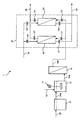
図1は、本実施形態に係る処理装置の構成の一例を示す模式図である。図1に示す処理装置1は、原水槽10、凝集処理手段の一例として、撹拌機11を備える凝集反応槽12及び凝集剤添加配管13を有する凝集処理装置、膜ろ過処理手段の一例としての膜ろ過装置14、吸脱着装置16を備えている。
FIG. 1 is a schematic view showing an example of the configuration of the processing apparatus according to the present embodiment. The treatment device 1 shown in FIG. 1 is an example of a
吸脱着装置16は、2つの活性炭フィルタ(第1活性炭フィルタ18、第2活性炭フィルタ20)を備えている。吸脱着装置16では、以下で説明するように、活性炭フィルタに臭気物質を吸着させる吸着処理、加熱ガスにより活性炭フィルタから臭気物質を脱着させる脱着処理が行われる。
The suction /
原水槽10の入口には、原水配管22が接続されている。接続配管24aの一端は原水槽10の出口に接続され、他端が凝集反応槽12の入口に接続されている。また、接続配管24bの一端は凝集反応槽12の出口に接続され、他端は膜ろ過装置14の入口に接続されている。また、接続配管24cの一端は膜ろ過装置14の出口に接続され、他端は分岐して、第1活性炭フィルタ18の被処理水入口及び第2活性炭フィルタ20の被処理水入口にそれぞれ接続されている。また、処理水配管26の一端は分岐して、第1活性炭フィルタ18の処理水出口及び第2活性炭フィルタ20の処理水出口にそれぞれ接続され、他端は例えば不図示の処理水槽に接続されている。また、加熱ガス供給配管28の一端は分岐して、第1活性炭フィルタ18のガス入口及び第2活性炭フィルタ20のガス入口にそれぞれ接続され、他端は、例えば不図示の加熱ガス供給源に接続されている。また、排ガス配管30の一端は分岐して、第1活性炭フィルタ18のガス出口及び第2活性炭フィルタ20のガス出口にそれぞれ接続され、他端は、例えば不図示の燃焼装置に接続されている。接続配管24c、処理水配管26、加熱ガス供給配管28、排ガス配管30にはそれぞれバルブ(V1〜V8)が設置されている。
A
本実施形態の処理装置1の動作の一例を説明する。 An example of the operation of the processing device 1 of the present embodiment will be described.
処理装置1で処理される水は、臭気物質を含む水であれば特に制限されるものではないが、例えば、臭気物質の他に溶存性有機物や懸濁物質等を含む水でもよい。具体的には、水道水、地下水(例えば、井戸水、湧水、伏流水等)、地表水(例えば、河川水、湖沼水等)等である。 The water treated by the treatment apparatus 1 is not particularly limited as long as it contains an odorous substance, but may be, for example, water containing a dissolved organic substance, a suspended substance, or the like in addition to the odorous substance. Specifically, tap water, groundwater (for example, well water, spring water, underground water, etc.), surface water (for example, river water, lake water, etc.) and the like.
臭気物質とは、土臭、生ぐさ臭、腐敗臭、カビ臭などの原因となる有機化合物を意味しており、例えば、浄水場で問題となるカビ臭の原因となる臭気物質はジオスミンや2−MIB等が挙げられる。溶存性有機物は、例えば、フミン質、フルボ酸等の色度成分等である。以下、臭気物質を含む水を単に原水と称する。 The odorous substance means an organic compound that causes earthy odor, raw odor, putrefactive odor, musty odor, etc. For example, the odorous substance that causes the musty odor that becomes a problem in water purification plants is geosmin or 2-. MIB and the like can be mentioned. Dissolved organic substances are, for example, chromaticity components such as humic acid and fulvic acid. Hereinafter, water containing an odorous substance is simply referred to as raw water.
原水配管22から原水槽10内に貯留された原水は、接続配管24aを通り、凝集反応槽12に供給される。この際、凝集剤添加配管13から凝集剤が添加され、撹拌機11により原水と凝集剤とが混合され、原水中の懸濁物質、一部の溶存性有機物等がフロック化される(凝集処理)。
The raw water stored in the
凝集処理された処理水は、接続配管24bを通り、膜ろ過装置14に導入される。処理水中の懸濁物質、一部の溶存性有機物等は、膜ろ過装置14内のろ過膜により捕捉される(膜ろ過処理)。膜ろ過処理された処理水は、接続配管24cを通り、第1活性炭フィルタ18に導入される。ここでは、接続配管24cのバルブV1及び処理水配管26のバルブV3が開放され、接続配管24cのバルブV2及び処理水配管26のバルブV4が閉じられており、第2活性炭フィルタ20には通液されない状態としている。
The coagulated treated water passes through the connecting
第1活性炭フィルタ20により、処理水中の臭気物質及び残存する溶存性有機物等が吸着され(吸着処理)、吸着処理された処理水は、処理水配管26から排出される。所定時間経過後、接続配管24cのバルブV2を開、バルブV1を閉、処理水配管26のバルブV4を開、バルブV3を閉とし、第1活性炭フィルタ18への処理液の通液が停止され、第2活性炭フィルタ20への処理液の通液が開始される。この際、加熱ガス供給配管28のバルブV5及び排ガス配管30のバルブV7が開放され、加熱ガスが加熱ガス供給配管28から第1活性炭フィルタ18へ供給される。加熱ガスが第1活性炭フィルタ18に接触することで、吸着された臭気物質等が脱着される(脱着処理)。脱着された臭気物質等は排ガスとして排ガス配管30から排出され、不図示の燃焼装置等で熱分解処理される。以下、各配管のバルブの開閉を適宜切換え、第1活性炭フィルタ18と第2活性炭フィルタ20との間で、吸着処理及び脱着処理が交互に行われる。
The first activated
本実施形態のように、膜ろ過処理の前段で凝集処理を行うことで、原水中に含まれる溶存性有機物等が膜ろ過処理等で効率的に除去されるため、後段の活性炭フィルタへの負荷が低減される。これにより、活性炭フィルタの再生や交換のランニングコストを低減することが可能となる。特に、活性炭フィルタでの吸着処理時間を長くすることができるため、脱着処理の頻度を低減することが可能となり、活性炭フィルタの再生コストが低減される。また、脱着処理を行うことで、活性炭フィルタの再利用が可能となるため、活性炭フィルタの交換コストがより低減される。 By performing the coagulation treatment in the first stage of the membrane filtration treatment as in the present embodiment, dissolved organic substances and the like contained in the raw water are efficiently removed by the membrane filtration treatment and the like, so that the load on the activated carbon filter in the latter stage is applied. Is reduced. This makes it possible to reduce the running cost of regenerating or replacing the activated carbon filter. In particular, since the adsorption treatment time of the activated carbon filter can be lengthened, the frequency of the desorption treatment can be reduced, and the regeneration cost of the activated carbon filter can be reduced. Further, by performing the desorption treatment, the activated carbon filter can be reused, so that the replacement cost of the activated carbon filter can be further reduced.
以下、処理装置1の各構成について詳述する。 Hereinafter, each configuration of the processing device 1 will be described in detail.
凝集処理装置による凝集処理は、既述したように、原水に凝集剤を添加して、原水と凝集剤とを混合する凝集混和処理だけでなく、凝集反応槽12の後段に沈殿槽や加圧浮上槽を設置して、凝集反応槽12にてフロック化した不純物を沈殿槽や加圧浮上槽にて除去する凝集沈殿又は凝集加圧浮上処理を含んでいてもよい。すなわち、本明細書における凝集処理した処理水とは、凝集混和処理した処理水、又は凝集沈殿又は凝集加圧浮上した処理水を意味する。凝集沈殿又は凝集加圧浮上処理を含むことで、溶存性有機物や懸濁物質をより低減させた処理水を活性炭フィルタに供給することが可能となる。
As described above, the agglutination treatment by the agglutination treatment device is not only a coagulation-mixing treatment in which a coagulant is added to raw water and the raw water and the coagulant are mixed, but also a settling tank or pressurization after the
凝集処理で使用される凝集剤は、無機系凝集剤、有機系凝集剤等が挙げられる。これらは1種単独でも、併用してもよい。無機系凝集剤は、例えば、ポリ塩化アルミニウム、硫酸バンド、塩化第二鉄、硫酸第二鉄、塩化アルミニウム、硫酸アルミニウム等が挙げられる。また、有機系凝集剤は、例えば、ポリアクリルアミド系凝集剤、ポリスルホン酸系凝集剤、ポリアクリル酸系凝集剤、ポリアクリル酸エステル系凝集剤、ポリアミン系凝集剤、ポリメタクリル酸系凝集剤等の高分子凝集剤、界面活性剤等の低分子凝集剤(凝結剤)等が挙げられる。 Examples of the coagulant used in the coagulation treatment include an inorganic coagulant and an organic coagulant. These may be used alone or in combination. Examples of the inorganic flocculant include polyaluminum chloride, aluminum sulfate band, ferric chloride, ferric sulfate, aluminum chloride, aluminum sulfate and the like. The organic flocculants include, for example, polyacrylamide-based flocculants, polysulfonic acid-based flocculants, polyacrylic acid-based flocculants, polyacrylic acid ester-based flocculants, polyamine-based flocculants, polymethacrylic acid-based flocculants, and the like. Examples thereof include low molecular weight coagulants (coagulants) such as high molecular weight coagulants and surfactants.
凝集剤の添加濃度は、膜ろ過装置14に設置されたろ過膜のファウリングを抑制することができる点で、例えば、原水中の溶存性有機物の濃度(mg/L)に対して5倍〜75倍の範囲であることが好ましく、経済性の観点から5倍〜20倍の範囲であることがより好ましい。
The concentration of the flocculant added is, for example, 5 times to the concentration of the dissolved organic matter (mg / L) in the raw water in that the fouling of the filtration membrane installed in the
膜ろ過装置14は、例えば、ろ過膜を密閉可能な容器に収納した少なくとも1つのモジュールから構成されている。ろ過膜の形状は特に制限されるものではなく、例えば、中空糸膜、管状膜、平膜、スパイラル等が挙げられる。膜ろ過装置14の通水方式は、内圧型、外圧型等のあらゆる通水方式が適用可能であり、クロスフローろ過やデッドエンドろ過等のあらゆるろ過方法が適用可能である。
The
膜ろ過装置14に使用されるろ過膜は、例えば、限外ろ過膜(UF膜)、精密ろ過膜(MF膜)、逆浸透膜(RO膜)、ナノろ過膜(NF膜)等が挙げられる。材質は、例えば、ポリフッ化ビニリデン(PVDF)、ポリ塩化ビニル(PVC)、ポリエーテルサルフォン(PES)、セルロースアセテート(CA)等の有機膜、セラミック製の無機膜等が挙げられる。ろ過膜の細孔径は、例えば、0.1μm以下が好ましく、0.03μm以下がより好ましい。
Examples of the filtration membrane used in the
活性炭フィルタ(18,20)の形態としては、例えば、繊維状活性炭の原綿やシートでフィルタを形成したもの、繊維状活性炭を主成分とするシートを積層したもの、前記シートを同心円状に円筒状に巻き付けてカートリッジとしたもの、繊維状活性炭とバインダー又は粉末活性炭を水中に分散させ、金型に導入することにより円筒状あるいは円柱状のカートリッジに形成したもの等を用いることができる。 Examples of the activated carbon filter (18, 20) include a filter formed from raw cotton or a sheet of fibrous activated carbon, a laminated sheet containing fibrous activated carbon as a main component, and the sheets concentrically cylindrical. It can be used as a cartridge by wrapping it around a cartridge, or a cartridge formed into a cylindrical or columnar cartridge by dispersing fibrous activated carbon and a binder or powdered activated carbon in water and introducing it into a mold.
活性炭フィルタ(18,20)に使用される繊維状活性炭の物性は、特に限定されるものではないが、BET比表面積が1000〜2000m2/g、平均細孔径が10〜50Åのものが好ましい。材質としては、例えば、石炭ピッチ系、石油ピッチ系、再生セルロース系、アクリル繊維系、フェノール繊維系等が挙げられる。 The physical properties of the fibrous activated carbon used in the activated carbon filter (18, 20) are not particularly limited, but those having a BET specific surface area of 1000 to 2000 m 2 / g and an average pore diameter of 10 to 50 Å are preferable. Examples of the material include coal pitch type, petroleum pitch type, regenerated cellulose type, acrylic fiber type, phenol fiber type and the like.
活性炭フィルタ(18,20)への処理水の通水条件は、特に制限されるものではないが、例えば、SVは1500〜20000(1/h)の範囲であることが好ましい。 The conditions for passing the treated water through the activated carbon filters (18, 20) are not particularly limited, but for example, the SV is preferably in the range of 1500 to 20000 (1 / h).
活性炭フィルタ(18,20)への加熱ガスの通気条件は、特に制限されるものではないが、例えば、活性炭1kgあたりに対する加熱ガスの流量が1〜2kg/hであることが好ましい。 The conditions for venting the heating gas to the activated carbon filters (18, 20) are not particularly limited, but for example, the flow rate of the heating gas per 1 kg of activated carbon is preferably 1 to 2 kg / h.
加熱ガスは、活性炭フィルタ(18,20)から臭気物質を脱着することできる温度以上のガスであれば特に制限されるものではない。加熱ガスは、例えば、水蒸気、加熱空気、加熱不活性ガス等が挙げられる。 The heating gas is not particularly limited as long as it is a gas having a temperature or higher at which odorous substances can be desorbed from the activated carbon filter (18, 20). Examples of the heating gas include steam, heated air, and a heated inert gas.
加熱ガスは、図1に示す処理装置1とは別個の装置で排出された加熱ガスを利用してもよいし、加熱ガスを発生する加熱ガス発生装置を設置し、加熱ガス発生装置から加熱ガスを活性炭フィルタ(18,20)に供給してもよい。加熱ガス発生装置の構成は、例えば、ガス充填タンク、ヒータ、送風器等から構成される。 As the heating gas, the heating gas discharged by a device separate from the processing device 1 shown in FIG. 1 may be used, or a heating gas generator for generating the heating gas is installed, and the heating gas is generated from the heating gas generator. May be supplied to the activated carbon filter (18, 20). The structure of the heating gas generator includes, for example, a gas filling tank, a heater, a blower, and the like.
吸脱着装置16は、2つの活性炭フィルタを備えているが、これに制限されるものではなく、1つ以上の活性炭フィルタを備えていればよい。また、吸脱着装置16では、第1の活性炭フィルタ18、第2活性炭フィルタ20との間で、吸着処理及び脱着処理を交互に行っているが、この態様に制限されるものではない。
The suction /
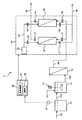
図2は、他の実施形態に係る処理装置の構成の一例を示す模式図である。図2に示す処理装置2において、図1に示す処理装置1と同様の構成については同一の符号を付しその説明を省略する。図2に示す処理装置2は、加熱ガス発生装置32を有する吸脱着装置16、臭気センサ34、制御装置36を備える。
FIG. 2 is a schematic view showing an example of the configuration of the processing apparatus according to another embodiment. In the
臭気センサ34は、原水槽10に設置され、原水から発生する臭気を検知する。臭気センサ34は、特に制限はなく、例えば、市販の熱線型焼結半導体センサなどを用いることができる。臭気センサ34は、制御装置36と電気的に接続されており、臭気センサ34により測定された値が制御装置36に送信される。
The
制御装置36は、プロセッサ及びメモリを備え、機能ブロックとして演算部38、吸脱着制御部40を備える。制御装置36は、加熱ガス発生装置32、各配管のバルブ(V1〜V8)と電気的に接続されており、加熱ガス発生装置32の稼働・停止、各バルブ(V1〜V8)の開閉を制御する。
The
演算部38は、臭気センサ34により測定された値と、活性炭フィルタの吸着容量とに基づいて、脱着処理を行うタイミングを決定する。具体的には、原水の臭気と原水の臭気物質濃度との関係を満たす検量線が予め記憶されており、臭気センサ34により測定された値を当該検量線に当てはめて、原水中の臭気物質濃度(mg/L)を算出する。当該算出した原水中の臭気物質濃度と処理装置2の原水流量(L/h)から臭気物質の負荷(mg/h:単位時間当たりに処理する臭気物質量)を求める。原水流量は予め設定された値である。また、活性炭フィルタの吸着容量は、予め活性炭フィルタが破過するまでに吸着できた吸着物質量を測定する吸着試験により求めた値であり、活性炭フィルタが吸着できる吸着物質の総量(mg/kg−活性炭フィルタ)である。そして、活性炭フィルタの吸着容量(mg/kg−活性炭フィルタ)を臭気物質の負荷(mg/h)で除することにより時間を算出し、当該時間を脱着処理を行うタイミング(すなわち吸着処理を停止するタイミング)とする。
The
吸脱着制御部40は、演算部38により算出した時間が経過した時点で、各配管のバルブの開閉を制御して、例えば第1活性炭フィルタ18の吸着処理を停止し(この際、第2活性炭フィルタ20の吸着処理を開始してもよい)、また加熱ガス発生装置32を稼働させ、加熱ガスを例えば第1活性炭フィルタ18に供給し、脱着処理を開始する。所定時間経過後、吸脱着制御部40は、各配管のバルブの開閉を制御し、また、加熱ガス発生装置32を停止して、第1活性炭フィルタ18の脱着処理を終了する。なお、第2活性炭フィルタ20についても、同様に、上記算出した時間が経過した時点で、脱着処理を開始する。
The suction /
また、演算部38は、脱着処理後から臭気センサ34により所定の時間間隔で測定された値(例えば臭気濃度)と処理時間と処理流量をかけて脱着処理後からの臭気物質の負荷(mg)を算出してもよい。
(処理時間(h)×処理流量(L/h)×臭気濃度(mg/L)=臭気物質積算負荷(mg)
In addition, the
(Treatment time (h) x treatment flow rate (L / h) x odor concentration (mg / L) = odor substance integrated load (mg)
そして、吸脱着制御部40は、演算部38により算出された積算値(mg)が活性炭フィルタ装置の吸着容量(=吸着容量(mg/kg−活性炭フィルタ)×活性炭フィルタ量(kg−活性炭フィルタ))に所定の安全率をかけた値を超えた時点で、各配管のバルブの開閉、加熱ガス発生装置32の稼働を制御し、活性炭フィルタ(例えば第1活性炭フィルタ18)の吸着処理を停止させ、脱着処理を開始させてもよい。
Then, in the adsorption /
本実施形態では、原水を測定対象としているが、これに制限されるものではなく、凝集反応槽12又は接続配管24bにセンサを設置し、凝集処理した処理水を測定対象としてもよいし、接続配管24cにセンサを設置し、膜ろ過処理した処理水を測定対象としてもよい。活性炭フィルタに流入する処理水の水質をより高い精度で測定することが可能である点等から、膜ろ過処理した処理水を測定対象とすることが好ましい。
In the present embodiment, raw water is the measurement target, but the measurement target is not limited to this, and a sensor may be installed in the
なお、本実施形態では、上記測定対象のうち少なくともいずれか1つであればよいが、複数の測定対象から臭気等を測定してもよい。 In this embodiment, at least one of the above measurement targets may be used, but odor and the like may be measured from a plurality of measurement targets.
以下、実施例及び比較例を挙げ、本発明をより具体的に詳細に説明するが、本発明は、以下の実施例に限定されるものではない。 Hereinafter, the present invention will be described in more detail with reference to Examples and Comparative Examples, but the present invention is not limited to the following Examples.
(実施例1)
図1に示す処理装置を用いて、1000ng/Lの臭気物質(ジェオスミン+2−MIB)、3mg/LのTOCを含む水を処理した。
(Example 1)
Water containing 1000 ng / L of odorous substance (geosmin + 2-MIB) and 3 mg / L of TOC was treated using the treatment apparatus shown in FIG.
実施例1の膜ろ過装置として、UF膜装置を用いた。UF膜装置の詳細は以下に示す通りである。
寸法:外径230mm×高さ2400mm
ろ過面積(膜面積):77m2
限外ろ過膜:中空糸膜、PVDF製、公称孔径0.01μm(公称分画分子量360,000Da)
ろ過方式:外圧式デッドエンドろ過
処理流量:9.6m3/h
A UF membrane device was used as the membrane filtration device of Example 1. Details of the UF membrane apparatus are as shown below.
Dimensions: Outer diameter 230 mm x height 2400 mm
Filtration area (membrane area): 77m2
Ultrafiltration membrane: Hollow fiber membrane, made of PVDF, nominal pore size 0.01 μm (nominal molecular weight cut-off molecular weight 360,000 Da)
Filtration method: External pressure type dead end filtration Processing flow rate: 9.6 m 3 / h
実施例1の活性炭フィルタの詳細は以下に示す通りである。
寸法:3m×3m×3m
活性炭:細孔径10Å、比表面積1500m2/gの繊維状活性炭
処理流量:9.6m3/h
The details of the activated carbon filter of Example 1 are as shown below.
Dimensions: 3m x 3m x 3m
Activated carbon: Fibrous activated carbon with pore diameter of 10 Å and specific surface area of 1500 m2 / g Treatment flow rate: 9.6 m3 / h
1000ng/Lの臭気物質(ジェオスミン+2−MIB)、3mg/LのTOCを含む水に、無機系凝集剤としてポリ塩化アルミニウムを20ppm添加し、凝集処理を行った後、処理水を膜ろ過装置(UF膜装置)に通水し、膜ろ過処理を行った。膜ろ過処理後の処理水を活性炭フィルタに通液し、吸着処理を行った。活性炭フィルタから排出された処理水中の臭気物質濃度が5ng/L以上となった時点で吸着処理を停止し、活性炭フィルタに、活性炭1kgあたりに対する加熱ガスの流量が1〜2kg/hの流量で水蒸気を供給し分脱着処理を行った。このような吸着処理及び脱着処理を第1活性炭フィルタ及び第2活性炭フィルタとの間で交互に行った。 20 ppm of polyaluminum chloride as an inorganic flocculant is added to water containing 1000 ng / L odorous substance (geosmin + 2-MIB) and 3 mg / L TOC, and after coagulation treatment, the treated water is filtered through a membrane filtration device ( Water was passed through the UF membrane device) to perform a membrane filtration treatment. The treated water after the membrane filtration treatment was passed through an activated carbon filter for adsorption treatment. When the concentration of odorous substances in the treated water discharged from the activated carbon filter reaches 5 ng / L or more, the adsorption treatment is stopped, and steam is applied to the activated carbon filter at a flow rate of heating gas per 1 kg of activated carbon at a flow rate of 1 to 2 kg / h. Was supplied and desorption processing was performed. Such adsorption treatment and desorption treatment were alternately performed between the first activated carbon filter and the second activated carbon filter.
(比較例1)
凝集処理を行わずに、膜ろ過処理及び活性炭フィルタによる吸着処理を行ったこと、脱着処理を行わなかったこと以外は、実施例1と同様の処理を行った。
(Comparative Example 1)
The same treatment as in Example 1 was carried out except that the membrane filtration treatment, the adsorption treatment with an activated carbon filter, and the desorption treatment were not performed without performing the aggregation treatment.
(実施例2)
脱着処理を行わなかったこと以外は、実施例1と同様の処理を行った。
(Example 2)
The same treatment as in Example 1 was carried out except that the desorption treatment was not carried out.
凝集処理を行わなかった比較例1では、吸着処理時間は1000時間であったが、実施例1及び実施例2では吸着処理時間は2400時間であった。すなわち、凝集処理を行うことで、活性炭フィルタの吸着時間を長くすることが可能となるため、ランニングコストの低減を図ることが可能であると言える。特に、水処理中の脱着処理の回数を減らすことができるため、再生コストの低減を図ることが可能である。また、実施例1では、脱着処理により、活性炭フィルタの吸着性能を回復させることができ、活性炭フィルタを交換することなく、安定した水処理が可能であった。 In Comparative Example 1 in which the aggregation treatment was not performed, the adsorption treatment time was 1000 hours, but in Examples 1 and 2, the adsorption treatment time was 2400 hours. That is, it can be said that the running cost can be reduced because the adsorption time of the activated carbon filter can be lengthened by performing the coagulation treatment. In particular, since the number of desorption treatments during water treatment can be reduced, it is possible to reduce the regeneration cost. Further, in Example 1, the adsorption performance of the activated carbon filter could be restored by the desorption treatment, and stable water treatment was possible without replacing the activated carbon filter.
(実施例3)
処理対象排水として、色度成分であるフミン質を0.54mg/L含む水を用いた。当該水にポリ塩化アルミニウムを10、20、30、又は40mg/L添加し、凝集処理を行った後、処理水をUF膜装置に通水し、膜ろ過処理を行った。UF膜装置及び膜ろ過処理条件は実施例1と同様とした。
(Example 3)
As the wastewater to be treated, water containing 0.54 mg / L of humic acid, which is a chromaticity component, was used. Polyaluminum chloride was added to the water at 10, 20, 30, or 40 mg / L to perform agglomeration treatment, and then the treated water was passed through a UF membrane apparatus to perform a membrane filtration treatment. The UF membrane apparatus and membrane filtration treatment conditions were the same as in Example 1.
(比較例2)
処理対象排水として、色度成分であるフミン質を0.54mg/L含む水に対して凝集処理を行わなかったこと以外は、実施例3と同様の処理を行った。
(Comparative Example 2)
As the wastewater to be treated, the same treatment as in Example 3 was carried out except that the water containing 0.54 mg / L of humic acid, which is a chromaticity component, was not subjected to the coagulation treatment.
実施例3及び比較例2で得られた処理水中のフミン質濃度を測定した。その結果を表1に示す。 The humic acid concentration in the treated water obtained in Example 3 and Comparative Example 2 was measured. The results are shown in Table 1.

ポリ塩化アルミニウムを添加して凝集処理を行った後、UF膜装置で膜ろ過処理を行った実施例3は、フミン質濃度が低下した処理水が得られた。一方、ポリ塩化アルミニウムを添加せず、UF膜装置で膜ろ過処理を行った比較例2は、UF膜でフミン質をほとんど除去できず、得られた処理水中のフミン質濃度は原水中のフミン質濃度とほとんど変わらなかった。これにより、色度成分を含む場合に、活性炭フィルタの前段で凝集処理を行ってUF膜装置で処理することで、色度成分をUF膜で処理することが可能となり、後段の活性炭フィルタを臭気成分の除去に効率的に利用することが可能となる。 In Example 3 in which polyaluminum chloride was added to perform aggregation treatment and then membrane filtration treatment was performed with a UF membrane apparatus, treated water having a reduced humic acid concentration was obtained. On the other hand, in Comparative Example 2 in which the membrane filtration treatment was performed by the UF membrane apparatus without adding polyaluminum chloride, the humic acid could hardly be removed by the UF membrane, and the humic acid concentration in the obtained treated water was the humic acid in the raw water. It was almost the same as the quality concentration. As a result, when the chromaticity component is contained, the chromaticity component can be treated with the UF membrane by performing the aggregation treatment in the front stage of the activated carbon filter and treating with the UF membrane apparatus, and the activated carbon filter in the rear stage is odorous. It can be efficiently used for removing components.
1,2 処理装置、10 原水槽、11 撹拌機、12 凝集反応槽、13 凝集剤添加配管、14 膜ろ過装置、16 吸脱着装置、18 第1活性炭フィルタ、20 第2活性炭フィルタ、22 原水配管、24a〜24c 接続配管、26 処理水配管、28 加熱ガス供給配管、30 排ガス配管、32 加熱ガス発生装置、34 臭気センサ、 36 制御装置、38 演算部、40 吸脱着制御部。 1, 2 Treatment equipment, 10 Raw water tank, 11 Stirrer, 12 Coagulation reaction tank, 13 Coagulant addition pipe, 14 Film filtration device, 16 Adsorption / desorption device, 18 1st activated carbon filter, 20 2nd activated carbon filter, 22 Raw water pipe , 24a to 24c connection pipe, 26 treated water pipe, 28 heating gas supply pipe, 30 exhaust gas pipe, 32 heating gas generator, 34 odor sensor, 36 control device, 38 calculation unit, 40 suction / detachment control unit.
Claims (8)
前記凝集処理した処理水を膜ろ過処理する膜ろ過処理工程と、
前記膜ろ過処理した処理水を活性炭フィルタに接触させて、前記臭気物質を吸着させる吸着処理工程と、
前記活性炭フィルタに加熱ガスを接触させて、前記吸着した臭気物質を脱着させる脱着処理工程と、を備え、
前記臭気物質を含む水、前記凝集処理した処理水及び前記膜ろ過処理した処理水のうち少なくともいずれか1つに対して、臭気を測定し、当該測定値と前記活性炭フィルタの吸着容量とに基づき、前記脱着処理工程を行うタイミングを決定することを特徴とする臭気物質を含む水の処理方法。 A coagulation treatment step in which a coagulant is added to water containing an odorous substance to perform a coagulation treatment,
The membrane filtration treatment step of membrane filtration treatment of the aggregated treated water and
The adsorption treatment step of bringing the treated water subjected to the membrane filtration treatment into contact with the activated carbon filter to adsorb the odorous substance, and
A desorption treatment step of bringing a heating gas into contact with the activated carbon filter to desorb the adsorbed odorous substance is provided .
The odor was measured with respect to at least one of the water containing the odorous substance, the aggregated treated water, and the membrane-filtered treated water, and based on the measured value and the adsorption capacity of the activated carbon filter. , A method for treating water containing an odorous substance, which comprises determining the timing of performing the desorption treatment step .
前記凝集処理した処理水を膜ろ過処理する膜ろ過処理手段と、
活性炭フィルタを有し、前記膜ろ過処理した処理水を前記活性炭フィルタに接触させることで前記臭気物質を吸着させる吸着処理工程を行う吸着手段と、
前記活性炭フィルタに加熱ガスを接触させて、前記吸着した臭気物質を脱着させる脱着処理工程を行う脱着手段と、を備え、
前記臭気物質を含む水、前記凝集処理した処理水及び前記膜ろ過処理した処理水のうち少なくともいずれか1つに対して、臭気を測定する測定手段を有し、前記脱着処理手段による脱着処理工程を行うタイミングは、前記測定手段により測定された測定値と前記活性炭フィルタとの吸着容量とに基づき決定されることを特徴とする臭気物質を含む水の処理装置。 A coagulation treatment means for performing a coagulation treatment by adding a coagulant to water containing an odorous substance,
A membrane filtration treatment means for membrane filtration treatment of the aggregated treated water,
An adsorption means having an activated carbon filter and performing an adsorption treatment step of adsorbing the odorous substance by bringing the treated water subjected to the membrane filtration treatment into contact with the activated carbon filter.
The activated carbon filter is provided with a desorption means for performing a desorption treatment step of bringing the heated gas into contact with the activated carbon filter to desorb the adsorbed odorous substance .
A desorption treatment step of the desorption treatment means, which comprises a measuring means for measuring the odor of at least one of the water containing the odorous substance, the aggregated treated water and the membrane filtration treated water. A water treatment apparatus containing an odorous substance, which is determined based on the measured value measured by the measuring means and the adsorption capacity of the activated carbon filter .
前記第1活性炭フィルタと前記第2活性炭フィルタとの間で、前記吸着処理工程及び前記脱着処理工程を交互に行うことを特徴とする請求項1〜3のいずれか1項に記載の臭気物質を含む水の処理方法。The odorous substance according to any one of claims 1 to 3, wherein the adsorption treatment step and the desorption treatment step are alternately performed between the first activated carbon filter and the second activated carbon filter. How to treat water containing.
前記第1活性炭フィルタと前記第2活性炭フィルタとの間で、前記吸着処理工程及び前記脱着処理工程を交互に行うことを特徴とする請求項4〜6のいずれか1項に記載の臭気物質を含む水の処理装置。The odorous substance according to any one of claims 4 to 6, wherein the adsorption treatment step and the desorption treatment step are alternately performed between the first activated carbon filter and the second activated carbon filter. Water treatment equipment containing.
Priority Applications (1)
| Application Number | Priority Date | Filing Date | Title |
|---|---|---|---|
| JP2017043035A JP6830833B2 (en) | 2017-03-07 | 2017-03-07 | Treatment method and treatment equipment for water containing odorous substances |
Applications Claiming Priority (1)
| Application Number | Priority Date | Filing Date | Title |
|---|---|---|---|
| JP2017043035A JP6830833B2 (en) | 2017-03-07 | 2017-03-07 | Treatment method and treatment equipment for water containing odorous substances |
Publications (2)
| Publication Number | Publication Date |
|---|---|
| JP2018143983A JP2018143983A (en) | 2018-09-20 |
| JP6830833B2 true JP6830833B2 (en) | 2021-02-17 |
Family
ID=63589733
Family Applications (1)
| Application Number | Title | Priority Date | Filing Date |
|---|---|---|---|
| JP2017043035A Active JP6830833B2 (en) | 2017-03-07 | 2017-03-07 | Treatment method and treatment equipment for water containing odorous substances |
Country Status (1)
| Country | Link |
|---|---|
| JP (1) | JP6830833B2 (en) |
Families Citing this family (4)
| Publication number | Priority date | Publication date | Assignee | Title |
|---|---|---|---|---|
| CN112850972B (en) * | 2021-03-04 | 2023-04-18 | 山东蓝驰环境科技股份有限公司 | Buried domestic sewage treatment integrated equipment |
| CN117482932B (en) * | 2023-09-26 | 2024-04-16 | 湖南中寅环保设备制造有限公司 | Regeneration method of waste lubricating oil refined adsorbent |
| CN118183970B (en) * | 2024-05-16 | 2024-07-09 | 庄浪县鑫喜淀粉加工有限责任公司 | Potato protein sewage treatment device with self-cleaning function |
| JP7810322B1 (en) * | 2024-07-04 | 2026-02-03 | 東洋紡エムシー株式会社 | Water Treatment Systems |
Family Cites Families (8)
| Publication number | Priority date | Publication date | Assignee | Title |
|---|---|---|---|---|
| JPS6142394A (en) * | 1984-08-07 | 1986-02-28 | Zousui Sokushin Center | Treatment of water |
| JPH07214049A (en) * | 1994-02-07 | 1995-08-15 | Matsushita Electric Ind Co Ltd | Bathtub purifier |
| JPH07328606A (en) * | 1994-06-03 | 1995-12-19 | Toto Ltd | Concentrical city water purifying device for household |
| WO2006019240A1 (en) * | 2004-08-16 | 2006-02-23 | Jeongsoo Enginerring Co., Ltd. | Carbon fiber structures for water purification plant and purifying methods using the same |
| JP5282864B2 (en) * | 2007-08-07 | 2013-09-04 | 栗田工業株式会社 | Membrane separation method and membrane separation apparatus |
| JP5698630B2 (en) * | 2011-09-16 | 2015-04-08 | 株式会社タカギ | Central water purification system |
| JP6165598B2 (en) * | 2013-11-13 | 2017-07-19 | 水ing株式会社 | Regeneration method of plant-based spherical activated carbon and reuse method of the regenerated plant-based spherical activated carbon in water purification treatment |
| JP6311342B2 (en) * | 2014-02-17 | 2018-04-18 | 東洋紡株式会社 | Wastewater treatment system |
-
2017
- 2017-03-07 JP JP2017043035A patent/JP6830833B2/en active Active
Also Published As
| Publication number | Publication date |
|---|---|
| JP2018143983A (en) | 2018-09-20 |
Similar Documents
| Publication | Publication Date | Title |
|---|---|---|
| JP6830833B2 (en) | Treatment method and treatment equipment for water containing odorous substances | |
| CN100531870C (en) | Membrane module and water treatment system | |
| US9096447B2 (en) | Water treatment system with carbon regeneration circuit | |
| Cui et al. | Granular iron oxide adsorbents to control natural organic matter and membrane fouling in ultrafiltration water treatment | |
| Shankar et al. | Evaluation of biochar-ultrafiltration membrane processes for humic acid removal under various hydrodynamic, pH, ionic strength, and pressure conditions | |
| Lee et al. | Efficient phosphorus removal from MBR effluent with heated aluminum oxide particles (HAOPs) | |
| Kang et al. | Why does a mineral oxide adsorbent control fouling better than powdered activated carbon in hybrid ultrafiltration water treatment? | |
| HUP0800248A2 (en) | Installation and process for preparation of sorbents used for elimination of arsenic from drincing water | |
| JP3698093B2 (en) | Water treatment method and water treatment apparatus | |
| KR101389450B1 (en) | Desalination apparatus and desalinating method thereof | |
| Rawat et al. | A hybrid ultrafiltration membrane process using a low-cost laterite based adsorbent for efficient arsenic removal | |
| JP6311342B2 (en) | Wastewater treatment system | |
| KR101642087B1 (en) | Improved method and apparatus for water treatment by using active carbon | |
| KR20130132020A (en) | High-recovery nf/ro water purification system with inter-stage demineralization process | |
| JP6816292B2 (en) | Water treatment method and water treatment equipment | |
| JP2014087787A (en) | Processing method and processing device for manganese-containing water | |
| JP2013095886A (en) | Method for recovering oil from extra heavy oil layer | |
| US20170348618A1 (en) | Filter medium, process for producing filter medium, filtration device, method for operating filtration device, and filtration system | |
| JPS62110795A (en) | High purity water production equipment | |
| AU2014363130A1 (en) | Process for treating concentrated brine | |
| Jang et al. | Performance of ultrafiltration membrane process combined with coagulation/sedimentation | |
| JP2007000727A (en) | Operation method of membrane separation activated sludge treatment equipment | |
| JP2008062223A (en) | Membrane filtering method and membrane filtering system | |
| CN103253803A (en) | Pure water treatment equipment | |
| CN109160657A (en) | A kind of processing method of polyelectrolyte waste water |
Legal Events
| Date | Code | Title | Description |
|---|---|---|---|
| A621 | Written request for application examination |
Free format text: JAPANESE INTERMEDIATE CODE: A621 Effective date: 20191223 |
|
| A977 | Report on retrieval |
Free format text: JAPANESE INTERMEDIATE CODE: A971007 Effective date: 20200923 |
|
| A131 | Notification of reasons for refusal |
Free format text: JAPANESE INTERMEDIATE CODE: A131 Effective date: 20201013 |
|
| A521 | Request for written amendment filed |
Free format text: JAPANESE INTERMEDIATE CODE: A523 Effective date: 20201207 |
|
| TRDD | Decision of grant or rejection written | ||
| A01 | Written decision to grant a patent or to grant a registration (utility model) |
Free format text: JAPANESE INTERMEDIATE CODE: A01 Effective date: 20210105 |
|
| A61 | First payment of annual fees (during grant procedure) |
Free format text: JAPANESE INTERMEDIATE CODE: A61 Effective date: 20210127 |
|
| R150 | Certificate of patent or registration of utility model |
Ref document number: 6830833 Country of ref document: JP Free format text: JAPANESE INTERMEDIATE CODE: R150 |
|
| R250 | Receipt of annual fees |
Free format text: JAPANESE INTERMEDIATE CODE: R250 |
|
| R250 | Receipt of annual fees |
Free format text: JAPANESE INTERMEDIATE CODE: R250 |
|
| R250 | Receipt of annual fees |
Free format text: JAPANESE INTERMEDIATE CODE: R250 |