JP6826323B2 - 振動制御装置 - Google Patents
振動制御装置 Download PDFInfo
- Publication number
- JP6826323B2 JP6826323B2 JP2017167341A JP2017167341A JP6826323B2 JP 6826323 B2 JP6826323 B2 JP 6826323B2 JP 2017167341 A JP2017167341 A JP 2017167341A JP 2017167341 A JP2017167341 A JP 2017167341A JP 6826323 B2 JP6826323 B2 JP 6826323B2
- Authority
- JP
- Japan
- Prior art keywords
- vibration
- vibrating body
- circuit
- resistor
- resistance
- Prior art date
- Legal status (The legal status is an assumption and is not a legal conclusion. Google has not performed a legal analysis and makes no representation as to the accuracy of the status listed.)
- Active
Links
- 239000003990 capacitor Substances 0.000 description 18
- 238000013016 damping Methods 0.000 description 15
- 230000000694 effects Effects 0.000 description 13
- 230000003071 parasitic effect Effects 0.000 description 10
- 230000007423 decrease Effects 0.000 description 8
- 238000010586 diagram Methods 0.000 description 7
- 238000000034 method Methods 0.000 description 7
- 230000005284 excitation Effects 0.000 description 5
- 238000004364 calculation method Methods 0.000 description 4
- 238000000691 measurement method Methods 0.000 description 4
- 230000004048 modification Effects 0.000 description 4
- 238000012986 modification Methods 0.000 description 4
- 238000005516 engineering process Methods 0.000 description 3
- 238000005259 measurement Methods 0.000 description 3
- 238000004088 simulation Methods 0.000 description 3
- 238000006243 chemical reaction Methods 0.000 description 2
- 230000003247 decreasing effect Effects 0.000 description 2
- 230000001629 suppression Effects 0.000 description 2
- NAWXUBYGYWOOIX-SFHVURJKSA-N (2s)-2-[[4-[2-(2,4-diaminoquinazolin-6-yl)ethyl]benzoyl]amino]-4-methylidenepentanedioic acid Chemical compound C1=CC2=NC(N)=NC(N)=C2C=C1CCC1=CC=C(C(=O)N[C@@H](CC(=C)C(O)=O)C(O)=O)C=C1 NAWXUBYGYWOOIX-SFHVURJKSA-N 0.000 description 1
- 230000002238 attenuated effect Effects 0.000 description 1
- 238000001514 detection method Methods 0.000 description 1
Images
Classifications
-
- B—PERFORMING OPERATIONS; TRANSPORTING
- B06—GENERATING OR TRANSMITTING MECHANICAL VIBRATIONS IN GENERAL
- B06B—METHODS OR APPARATUS FOR GENERATING OR TRANSMITTING MECHANICAL VIBRATIONS OF INFRASONIC, SONIC, OR ULTRASONIC FREQUENCY, e.g. FOR PERFORMING MECHANICAL WORK IN GENERAL
- B06B1/00—Methods or apparatus for generating mechanical vibrations of infrasonic, sonic, or ultrasonic frequency
- B06B1/02—Methods or apparatus for generating mechanical vibrations of infrasonic, sonic, or ultrasonic frequency making use of electrical energy
- B06B1/06—Methods or apparatus for generating mechanical vibrations of infrasonic, sonic, or ultrasonic frequency making use of electrical energy operating with piezoelectric effect or with electrostriction
-
- F—MECHANICAL ENGINEERING; LIGHTING; HEATING; WEAPONS; BLASTING
- F16—ENGINEERING ELEMENTS AND UNITS; GENERAL MEASURES FOR PRODUCING AND MAINTAINING EFFECTIVE FUNCTIONING OF MACHINES OR INSTALLATIONS; THERMAL INSULATION IN GENERAL
- F16F—SPRINGS; SHOCK-ABSORBERS; MEANS FOR DAMPING VIBRATION
- F16F15/00—Suppression of vibrations in systems; Means or arrangements for avoiding or reducing out-of-balance forces, e.g. due to motion
- F16F15/02—Suppression of vibrations of non-rotating, e.g. reciprocating systems; Suppression of vibrations of rotating systems by use of members not moving with the rotating systems
-
- G—PHYSICS
- G10—MUSICAL INSTRUMENTS; ACOUSTICS
- G10H—ELECTROPHONIC MUSICAL INSTRUMENTS; INSTRUMENTS IN WHICH THE TONES ARE GENERATED BY ELECTROMECHANICAL MEANS OR ELECTRONIC GENERATORS, OR IN WHICH THE TONES ARE SYNTHESISED FROM A DATA STORE
- G10H1/00—Details of electrophonic musical instruments
- G10H1/32—Constructional details
-
- G—PHYSICS
- G10—MUSICAL INSTRUMENTS; ACOUSTICS
- G10H—ELECTROPHONIC MUSICAL INSTRUMENTS; INSTRUMENTS IN WHICH THE TONES ARE GENERATED BY ELECTROMECHANICAL MEANS OR ELECTRONIC GENERATORS, OR IN WHICH THE TONES ARE SYNTHESISED FROM A DATA STORE
- G10H3/00—Instruments in which the tones are generated by electromechanical means
-
- H—ELECTRICITY
- H02—GENERATION; CONVERSION OR DISTRIBUTION OF ELECTRIC POWER
- H02N—ELECTRIC MACHINES NOT OTHERWISE PROVIDED FOR
- H02N2/00—Electric machines in general using piezoelectric effect, electrostriction or magnetostriction
- H02N2/02—Electric machines in general using piezoelectric effect, electrostriction or magnetostriction producing linear motion, e.g. actuators; Linear positioners ; Linear motors
- H02N2/06—Drive circuits; Control arrangements or methods
-
- H—ELECTRICITY
- H04—ELECTRIC COMMUNICATION TECHNIQUE
- H04R—LOUDSPEAKERS, MICROPHONES, GRAMOPHONE PICK-UPS OR LIKE ACOUSTIC ELECTROMECHANICAL TRANSDUCERS; DEAF-AID SETS; PUBLIC ADDRESS SYSTEMS
- H04R3/00—Circuits for transducers, loudspeakers or microphones
Landscapes
- Engineering & Computer Science (AREA)
- Physics & Mathematics (AREA)
- Acoustics & Sound (AREA)
- Mechanical Engineering (AREA)
- General Engineering & Computer Science (AREA)
- Multimedia (AREA)
- Aviation & Aerospace Engineering (AREA)
- Signal Processing (AREA)
- Apparatuses For Generation Of Mechanical Vibrations (AREA)
- Vibration Prevention Devices (AREA)
- Circuit For Audible Band Transducer (AREA)
- General Electrical Machinery Utilizing Piezoelectricity, Electrostriction Or Magnetostriction (AREA)
Description
(A:実施形態)
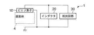
図1はこの発明の一実施形態である振動制御装置1の構成例を示すブロック図である。図1では、振動制御装置1による振動制御の対象となる振動体4が点線で図示されている。図1に示すように、振動制御装置1は、ピエゾ素子10と、インダクタ20と、抵抗回路30と、を有する。ピエゾ素子10は振動体4に固定される。例えば、振動体4がスピーカ筐体であれば、ピエゾ素子10は当該スピーカ筐体の表面に固定される。ピエゾ素子10は、振動体4に固有振動が発生している状態において振動体4の歪が最大となる箇所に固定されることが好ましい。ピエゾ素子10の2枚の電極のうちの一方は接地されており、その電位は基準電位(GND)となっている。
A1=R4/(R2+R4)・{(R3/R1)+1}…(1)
A2=((R5/R6)+1)…(2)
Vx=Rd・Ix…(3)
Vz1=Vx・(−A1)…(4)
Vz2={(R8−r)−r・A}・Vz1/R8…(5)
Vz3=Vz2・A2…(6)
Vz2=Vx・(−A1)・{(R8−r)−r・A}/R8…(7)
Vz3=Vx・(A2)・(−A1)・{(R8−r)−r・A}/R8…(8)
Vz3=−A0・Rd・Ix…(9)
A0=A1・A2・{(R8−r)−r・A}/R8…(10)
Rn=(Vx−Ix・Rd・A0)/Ix
=Vx/Ix−Rd・A0…(11)
Rn=Rd−Rd・A0
=(1−A0)・Rd…(12)
抵抗回路30の抵抗値Rnは、抵抗R301〜R306の抵抗値R1〜R6と、半固定抵抗R308の抵抗値rと、増幅器309のゲインAとに応じて定まり、A0>1のとき、すなわち、(1+A)・r<{1−1/(A1・A2)}・R8のとき負の値となる。抵抗R301〜R306の抵抗値R1〜R6および増幅器309のゲインAを予め適切な値に設定しておけば、半固定抵抗R308の抵抗値rを調整することで、抵抗回路30の抵抗値Rnを負の値から正の値まで連続的に変化させることができる。
以上が振動制御装置の構成である。
以上本発明の一実施形態について説明したが、以下の変形を加えても良い。
(1)上記実施形態では、抵抗回路30として、抵抗値を負の値から正の値まで変更可能な可変抵抗回路が採用されていた。しかし、振動体4の制振を行う必要はなく、励振を行えれば十分な場合には、抵抗回路30は、抵抗値を負の値の範囲で変更可能な可変抵抗回路であれば良い。逆に、振動体4の励振を行う必要はなく、制振を行えれば十分な場合には、抵抗回路30は、抵抗値を正の値の範囲で変更可能な可変抵抗回路であれば良い。また、振動体4の制振或いは励振を行う上で抵抗回路30の抵抗値の好適な値が予め判っているのであれば、抵抗回路30は可変抵抗である必要はない。
以上が疑似インダクタ回路20Aの構成である。
Δvc=−Δv1/(R205・jωCa)・・・(13)
Δip=−Δv1/(R203・R205・jωCa)・・・(14)
Δin=Δv1/(R204・R205・jωCa)・・・(15)
Δi1=Δin−Δip
=Δv1/(R204・R205・jωCa)
+Δv1/(R203・R205・jωCa)・・・(16)
Z=Δv1/Δi1
=Δv1/[Δv1/(R204・R205・jωCa)
+Δv1/(R203・R205・jωCa)]
=1/[1/(R204・R205・jωCa)
+1/(R203・R205・jωCa)]・・・(17)
Z=(R20・R205・jωCa)/2・・・(18)
このように疑似インダクタ回路20AのインピーダンスZは、計算上は抵抗成分がゼロであり、リアクタンスのみにより構成されている。
Ls=(R20・R205・Ca)/2・・・(19)
Res=Rd×(V1−V2)/V2…(13)
V2=V1×Rd/(Rd+Res)…(14)
Q=wo/(wp2−wp1)…(20)
Q=wo×Lm/(Res+Rd)…(21)
Q=1/(wo×Cm×(Res+Rd))…(22)
Claims (3)
- 振動体に固定されるピエゾ素子と、
前記ピエゾ素子に並列に接続されるインダクタおよび抵抗値が負の値の抵抗と
を具備することを特徴とする振動制御装置。 - 振動体に固定されるピエゾ素子と、
前記ピエゾ素子に並列に接続されるインダクタおよび抵抗値を負の値から正の値まで変更可能な可変抵抗と
を具備することを特徴とする振動制御装置。 - 前記インダクタは疑似インダクタであることを特徴とする請求項1または請求項2に記載の振動制御装置。
Priority Applications (2)
| Application Number | Priority Date | Filing Date | Title |
|---|---|---|---|
| JP2017167341A JP6826323B2 (ja) | 2017-08-31 | 2017-08-31 | 振動制御装置 |
| PCT/JP2018/020004 WO2019044070A1 (ja) | 2017-08-31 | 2018-05-24 | 振動制御装置 |
Applications Claiming Priority (1)
| Application Number | Priority Date | Filing Date | Title |
|---|---|---|---|
| JP2017167341A JP6826323B2 (ja) | 2017-08-31 | 2017-08-31 | 振動制御装置 |
Publications (3)
| Publication Number | Publication Date |
|---|---|
| JP2019047271A JP2019047271A (ja) | 2019-03-22 |
| JP2019047271A5 JP2019047271A5 (ja) | 2019-05-16 |
| JP6826323B2 true JP6826323B2 (ja) | 2021-02-03 |
Family
ID=65527359
Family Applications (1)
| Application Number | Title | Priority Date | Filing Date |
|---|---|---|---|
| JP2017167341A Active JP6826323B2 (ja) | 2017-08-31 | 2017-08-31 | 振動制御装置 |
Country Status (2)
| Country | Link |
|---|---|
| JP (1) | JP6826323B2 (ja) |
| WO (1) | WO2019044070A1 (ja) |
Family Cites Families (10)
| Publication number | Priority date | Publication date | Assignee | Title |
|---|---|---|---|---|
| US5783898A (en) * | 1996-02-26 | 1998-07-21 | Mcdonnell Douglas Corporation | Piezoelectric shunts for simultaneous vibration reduction and damping of multiple vibration modes |
| JP2003119719A (ja) * | 2001-10-17 | 2003-04-23 | Ishikawajima Harima Heavy Ind Co Ltd | 鉄橋の騒音低減方法及び装置 |
| US6870303B2 (en) * | 2002-05-08 | 2005-03-22 | Pohang University Of Science And Technology Foundation | Multi-mode vibration damping device and method using negative capacitance shunt circuits |
| JP2004048652A (ja) * | 2002-11-29 | 2004-02-12 | Toyo Commun Equip Co Ltd | 高周波圧電発振器 |
| JP4154261B2 (ja) * | 2003-03-12 | 2008-09-24 | リオン株式会社 | 音響・振動制御装置 |
| JP4714937B2 (ja) * | 2005-09-05 | 2011-07-06 | 独立行政法人 宇宙航空研究開発機構 | 構造物の制振装置 |
| JP5023282B2 (ja) * | 2007-04-10 | 2012-09-12 | 英彰 高島 | 圧電発振器 |
| JP2013239779A (ja) * | 2012-05-11 | 2013-11-28 | Asahi Kasei Electronics Co Ltd | 無線装置及びそれを備えたセンサ並びに無線タグ |
| US20140354112A1 (en) * | 2013-05-31 | 2014-12-04 | GM Global Technology Operations LLC | Piezoelectric resonators for reduction of noise and vibration in vehicle components |
| JP6862731B2 (ja) * | 2016-03-01 | 2021-04-21 | ヤマハ株式会社 | 制振装置 |
-
2017
- 2017-08-31 JP JP2017167341A patent/JP6826323B2/ja active Active
-
2018
- 2018-05-24 WO PCT/JP2018/020004 patent/WO2019044070A1/ja active Application Filing
Also Published As
| Publication number | Publication date |
|---|---|
| WO2019044070A1 (ja) | 2019-03-07 |
| JP2019047271A (ja) | 2019-03-22 |
Similar Documents
| Publication | Publication Date | Title |
|---|---|---|
| JP5010006B2 (ja) | モーショナルフィードバックシステム | |
| US10173243B2 (en) | Transducer driver attenuating input current frequency at maximum mechanical output | |
| JP5157959B2 (ja) | D級増幅器 | |
| US8291750B1 (en) | Resonant measurement system and method | |
| JP2015525872A5 (ja) | ||
| JP6862731B2 (ja) | 制振装置 | |
| KR20120027097A (ko) | 진동 스피커의 구동 제어 회로 | |
| KR101077383B1 (ko) | 관성력 센서 | |
| JP2007057262A (ja) | センサ回路 | |
| JP6826323B2 (ja) | 振動制御装置 | |
| JP2006197206A (ja) | スピーカ装置 | |
| JP2012156946A (ja) | 発振回路およびそれを用いた振動式センサ | |
| US9709533B2 (en) | Method and circuit for determining resonant frequencies of a resonant device | |
| JP2006017568A (ja) | 超音波流量計および受信回路 | |
| JP2013029349A (ja) | 衝撃電流検出装置 | |
| JP2003156524A (ja) | 電位固定装置および電位固定方法 | |
| JP2016050798A (ja) | チャージアンプ回路 | |
| Byju et al. | An enhanced voltage amplifier scheme insensitive to cable parasitic capacitance for interfacing piezoelectric sensors | |
| JP5884014B2 (ja) | 流れ計測装置 | |
| JP2009224865A (ja) | 電圧制御型弾性表面波発振器 | |
| JP4406863B2 (ja) | 振動型角速度センサ装置 | |
| RU2522827C2 (ru) | Устройство для измерения гармонических искажений электрического сигнала и его производных с высокой помехозащищенностью | |
| JP2016014689A (ja) | 衝撃電流検出装置 | |
| JP2005039325A (ja) | スピーカ装置およびその調整方法 | |
| JP6725781B2 (ja) | インピーダンス増減回路 |
Legal Events
| Date | Code | Title | Description |
|---|---|---|---|
| A621 | Written request for application examination |
Free format text: JAPANESE INTERMEDIATE CODE: A621 Effective date: 20190322 |
|
| A521 | Written amendment |
Free format text: JAPANESE INTERMEDIATE CODE: A523 Effective date: 20190405 |
|
| A131 | Notification of reasons for refusal |
Free format text: JAPANESE INTERMEDIATE CODE: A131 Effective date: 20200519 |
|
| A521 | Written amendment |
Free format text: JAPANESE INTERMEDIATE CODE: A523 Effective date: 20200714 |
|
| TRDD | Decision of grant or rejection written | ||
| A01 | Written decision to grant a patent or to grant a registration (utility model) |
Free format text: JAPANESE INTERMEDIATE CODE: A01 Effective date: 20201216 |
|
| A61 | First payment of annual fees (during grant procedure) |
Free format text: JAPANESE INTERMEDIATE CODE: A61 Effective date: 20201229 |
|
| R151 | Written notification of patent or utility model registration |
Ref document number: 6826323 Country of ref document: JP Free format text: JAPANESE INTERMEDIATE CODE: R151 |


