JP6824652B2 - 3D modeling method and 3D model manufacturing equipment - Google Patents
3D modeling method and 3D model manufacturing equipment Download PDFInfo
- Publication number
- JP6824652B2 JP6824652B2 JP2016136418A JP2016136418A JP6824652B2 JP 6824652 B2 JP6824652 B2 JP 6824652B2 JP 2016136418 A JP2016136418 A JP 2016136418A JP 2016136418 A JP2016136418 A JP 2016136418A JP 6824652 B2 JP6824652 B2 JP 6824652B2
- Authority
- JP
- Japan
- Prior art keywords
- material powder
- modeling
- laid
- layer
- irradiation output
- Prior art date
- Legal status (The legal status is an assumption and is not a legal conclusion. Google has not performed a legal analysis and makes no representation as to the accuracy of the status listed.)
- Active
Links
Images


Classifications
-
- B—PERFORMING OPERATIONS; TRANSPORTING
- B32—LAYERED PRODUCTS
- B32B—LAYERED PRODUCTS, i.e. PRODUCTS BUILT-UP OF STRATA OF FLAT OR NON-FLAT, e.g. CELLULAR OR HONEYCOMB, FORM
- B32B5/00—Layered products characterised by the non- homogeneity or physical structure, i.e. comprising a fibrous, filamentary, particulate or foam layer; Layered products characterised by having a layer differing constitutionally or physically in different parts
- B32B5/16—Layered products characterised by the non- homogeneity or physical structure, i.e. comprising a fibrous, filamentary, particulate or foam layer; Layered products characterised by having a layer differing constitutionally or physically in different parts characterised by features of a layer formed of particles, e.g. chips, powder or granules
-
- B—PERFORMING OPERATIONS; TRANSPORTING
- B22—CASTING; POWDER METALLURGY
- B22F—WORKING METALLIC POWDER; MANUFACTURE OF ARTICLES FROM METALLIC POWDER; MAKING METALLIC POWDER; APPARATUS OR DEVICES SPECIALLY ADAPTED FOR METALLIC POWDER
- B22F10/00—Additive manufacturing of workpieces or articles from metallic powder
- B22F10/20—Direct sintering or melting
- B22F10/28—Powder bed fusion, e.g. selective laser melting [SLM] or electron beam melting [EBM]
-
- B—PERFORMING OPERATIONS; TRANSPORTING
- B22—CASTING; POWDER METALLURGY
- B22F—WORKING METALLIC POWDER; MANUFACTURE OF ARTICLES FROM METALLIC POWDER; MAKING METALLIC POWDER; APPARATUS OR DEVICES SPECIALLY ADAPTED FOR METALLIC POWDER
- B22F10/00—Additive manufacturing of workpieces or articles from metallic powder
- B22F10/30—Process control
- B22F10/36—Process control of energy beam parameters
-
- B—PERFORMING OPERATIONS; TRANSPORTING
- B22—CASTING; POWDER METALLURGY
- B22F—WORKING METALLIC POWDER; MANUFACTURE OF ARTICLES FROM METALLIC POWDER; MAKING METALLIC POWDER; APPARATUS OR DEVICES SPECIALLY ADAPTED FOR METALLIC POWDER
- B22F10/00—Additive manufacturing of workpieces or articles from metallic powder
- B22F10/30—Process control
- B22F10/37—Process control of powder bed aspects, e.g. density
-
- B—PERFORMING OPERATIONS; TRANSPORTING
- B22—CASTING; POWDER METALLURGY
- B22F—WORKING METALLIC POWDER; MANUFACTURE OF ARTICLES FROM METALLIC POWDER; MAKING METALLIC POWDER; APPARATUS OR DEVICES SPECIALLY ADAPTED FOR METALLIC POWDER
- B22F12/00—Apparatus or devices specially adapted for additive manufacturing; Auxiliary means for additive manufacturing; Combinations of additive manufacturing apparatus or devices with other processing apparatus or devices
- B22F12/90—Means for process control, e.g. cameras or sensors
-
- B—PERFORMING OPERATIONS; TRANSPORTING
- B29—WORKING OF PLASTICS; WORKING OF SUBSTANCES IN A PLASTIC STATE IN GENERAL
- B29C—SHAPING OR JOINING OF PLASTICS; SHAPING OF MATERIAL IN A PLASTIC STATE, NOT OTHERWISE PROVIDED FOR; AFTER-TREATMENT OF THE SHAPED PRODUCTS, e.g. REPAIRING
- B29C64/00—Additive manufacturing, i.e. manufacturing of three-dimensional [3D] objects by additive deposition, additive agglomeration or additive layering, e.g. by 3D printing, stereolithography or selective laser sintering
- B29C64/10—Processes of additive manufacturing
- B29C64/141—Processes of additive manufacturing using only solid materials
- B29C64/153—Processes of additive manufacturing using only solid materials using layers of powder being selectively joined, e.g. by selective laser sintering or melting
-
- B—PERFORMING OPERATIONS; TRANSPORTING
- B29—WORKING OF PLASTICS; WORKING OF SUBSTANCES IN A PLASTIC STATE IN GENERAL
- B29C—SHAPING OR JOINING OF PLASTICS; SHAPING OF MATERIAL IN A PLASTIC STATE, NOT OTHERWISE PROVIDED FOR; AFTER-TREATMENT OF THE SHAPED PRODUCTS, e.g. REPAIRING
- B29C64/00—Additive manufacturing, i.e. manufacturing of three-dimensional [3D] objects by additive deposition, additive agglomeration or additive layering, e.g. by 3D printing, stereolithography or selective laser sintering
- B29C64/20—Apparatus for additive manufacturing; Details thereof or accessories therefor
- B29C64/205—Means for applying layers
- B29C64/214—Doctor blades
-
- B—PERFORMING OPERATIONS; TRANSPORTING
- B29—WORKING OF PLASTICS; WORKING OF SUBSTANCES IN A PLASTIC STATE IN GENERAL
- B29C—SHAPING OR JOINING OF PLASTICS; SHAPING OF MATERIAL IN A PLASTIC STATE, NOT OTHERWISE PROVIDED FOR; AFTER-TREATMENT OF THE SHAPED PRODUCTS, e.g. REPAIRING
- B29C64/00—Additive manufacturing, i.e. manufacturing of three-dimensional [3D] objects by additive deposition, additive agglomeration or additive layering, e.g. by 3D printing, stereolithography or selective laser sintering
- B29C64/20—Apparatus for additive manufacturing; Details thereof or accessories therefor
- B29C64/205—Means for applying layers
- B29C64/218—Rollers
-
- B—PERFORMING OPERATIONS; TRANSPORTING
- B29—WORKING OF PLASTICS; WORKING OF SUBSTANCES IN A PLASTIC STATE IN GENERAL
- B29C—SHAPING OR JOINING OF PLASTICS; SHAPING OF MATERIAL IN A PLASTIC STATE, NOT OTHERWISE PROVIDED FOR; AFTER-TREATMENT OF THE SHAPED PRODUCTS, e.g. REPAIRING
- B29C64/00—Additive manufacturing, i.e. manufacturing of three-dimensional [3D] objects by additive deposition, additive agglomeration or additive layering, e.g. by 3D printing, stereolithography or selective laser sintering
- B29C64/20—Apparatus for additive manufacturing; Details thereof or accessories therefor
- B29C64/264—Arrangements for irradiation
- B29C64/268—Arrangements for irradiation using laser beams; using electron beams [EB]
-
- B—PERFORMING OPERATIONS; TRANSPORTING
- B29—WORKING OF PLASTICS; WORKING OF SUBSTANCES IN A PLASTIC STATE IN GENERAL
- B29C—SHAPING OR JOINING OF PLASTICS; SHAPING OF MATERIAL IN A PLASTIC STATE, NOT OTHERWISE PROVIDED FOR; AFTER-TREATMENT OF THE SHAPED PRODUCTS, e.g. REPAIRING
- B29C64/00—Additive manufacturing, i.e. manufacturing of three-dimensional [3D] objects by additive deposition, additive agglomeration or additive layering, e.g. by 3D printing, stereolithography or selective laser sintering
- B29C64/30—Auxiliary operations or equipment
- B29C64/386—Data acquisition or data processing for additive manufacturing
- B29C64/393—Data acquisition or data processing for additive manufacturing for controlling or regulating additive manufacturing processes
-
- B—PERFORMING OPERATIONS; TRANSPORTING
- B32—LAYERED PRODUCTS
- B32B—LAYERED PRODUCTS, i.e. PRODUCTS BUILT-UP OF STRATA OF FLAT OR NON-FLAT, e.g. CELLULAR OR HONEYCOMB, FORM
- B32B5/00—Layered products characterised by the non- homogeneity or physical structure, i.e. comprising a fibrous, filamentary, particulate or foam layer; Layered products characterised by having a layer differing constitutionally or physically in different parts
- B32B5/22—Layered products characterised by the non- homogeneity or physical structure, i.e. comprising a fibrous, filamentary, particulate or foam layer; Layered products characterised by having a layer differing constitutionally or physically in different parts characterised by the presence of two or more layers which are next to each other and are fibrous, filamentary, formed of particles or foamed
- B32B5/30—Layered products characterised by the non- homogeneity or physical structure, i.e. comprising a fibrous, filamentary, particulate or foam layer; Layered products characterised by having a layer differing constitutionally or physically in different parts characterised by the presence of two or more layers which are next to each other and are fibrous, filamentary, formed of particles or foamed one layer being formed of particles, e.g. chips, granules, powder
-
- B—PERFORMING OPERATIONS; TRANSPORTING
- B22—CASTING; POWDER METALLURGY
- B22F—WORKING METALLIC POWDER; MANUFACTURE OF ARTICLES FROM METALLIC POWDER; MAKING METALLIC POWDER; APPARATUS OR DEVICES SPECIALLY ADAPTED FOR METALLIC POWDER
- B22F12/00—Apparatus or devices specially adapted for additive manufacturing; Auxiliary means for additive manufacturing; Combinations of additive manufacturing apparatus or devices with other processing apparatus or devices
- B22F12/60—Planarisation devices; Compression devices
- B22F12/63—Rollers
-
- B—PERFORMING OPERATIONS; TRANSPORTING
- B22—CASTING; POWDER METALLURGY
- B22F—WORKING METALLIC POWDER; MANUFACTURE OF ARTICLES FROM METALLIC POWDER; MAKING METALLIC POWDER; APPARATUS OR DEVICES SPECIALLY ADAPTED FOR METALLIC POWDER
- B22F3/00—Manufacture of workpieces or articles from metallic powder characterised by the manner of compacting or sintering; Apparatus specially adapted therefor ; Presses and furnaces
- B22F3/24—After-treatment of workpieces or articles
- B22F2003/247—Removing material: carving, cleaning, grinding, hobbing, honing, lapping, polishing, milling, shaving, skiving, turning the surface
-
- B—PERFORMING OPERATIONS; TRANSPORTING
- B22—CASTING; POWDER METALLURGY
- B22F—WORKING METALLIC POWDER; MANUFACTURE OF ARTICLES FROM METALLIC POWDER; MAKING METALLIC POWDER; APPARATUS OR DEVICES SPECIALLY ADAPTED FOR METALLIC POWDER
- B22F2999/00—Aspects linked to processes or compositions used in powder metallurgy
-
- B—PERFORMING OPERATIONS; TRANSPORTING
- B29—WORKING OF PLASTICS; WORKING OF SUBSTANCES IN A PLASTIC STATE IN GENERAL
- B29C—SHAPING OR JOINING OF PLASTICS; SHAPING OF MATERIAL IN A PLASTIC STATE, NOT OTHERWISE PROVIDED FOR; AFTER-TREATMENT OF THE SHAPED PRODUCTS, e.g. REPAIRING
- B29C64/00—Additive manufacturing, i.e. manufacturing of three-dimensional [3D] objects by additive deposition, additive agglomeration or additive layering, e.g. by 3D printing, stereolithography or selective laser sintering
- B29C64/20—Apparatus for additive manufacturing; Details thereof or accessories therefor
- B29C64/264—Arrangements for irradiation
- B29C64/268—Arrangements for irradiation using laser beams; using electron beams [EB]
- B29C64/273—Arrangements for irradiation using laser beams; using electron beams [EB] pulsed; frequency modulated
-
- B—PERFORMING OPERATIONS; TRANSPORTING
- B32—LAYERED PRODUCTS
- B32B—LAYERED PRODUCTS, i.e. PRODUCTS BUILT-UP OF STRATA OF FLAT OR NON-FLAT, e.g. CELLULAR OR HONEYCOMB, FORM
- B32B2264/00—Composition or properties of particles which form a particulate layer or are present as additives
- B32B2264/10—Inorganic particles
- B32B2264/105—Metal
-
- B—PERFORMING OPERATIONS; TRANSPORTING
- B32—LAYERED PRODUCTS
- B32B—LAYERED PRODUCTS, i.e. PRODUCTS BUILT-UP OF STRATA OF FLAT OR NON-FLAT, e.g. CELLULAR OR HONEYCOMB, FORM
- B32B2307/00—Properties of the layers or laminate
- B32B2307/50—Properties of the layers or laminate having particular mechanical properties
- B32B2307/538—Roughness
-
- B—PERFORMING OPERATIONS; TRANSPORTING
- B32—LAYERED PRODUCTS
- B32B—LAYERED PRODUCTS, i.e. PRODUCTS BUILT-UP OF STRATA OF FLAT OR NON-FLAT, e.g. CELLULAR OR HONEYCOMB, FORM
- B32B2307/00—Properties of the layers or laminate
- B32B2307/70—Other properties
- B32B2307/732—Dimensional properties
-
- B—PERFORMING OPERATIONS; TRANSPORTING
- B32—LAYERED PRODUCTS
- B32B—LAYERED PRODUCTS, i.e. PRODUCTS BUILT-UP OF STRATA OF FLAT OR NON-FLAT, e.g. CELLULAR OR HONEYCOMB, FORM
- B32B2310/00—Treatment by energy or chemical effects
- B32B2310/08—Treatment by energy or chemical effects by wave energy or particle radiation
- B32B2310/0806—Treatment by energy or chemical effects by wave energy or particle radiation using electromagnetic radiation
- B32B2310/0825—Treatment by energy or chemical effects by wave energy or particle radiation using electromagnetic radiation using IR radiation
-
- B—PERFORMING OPERATIONS; TRANSPORTING
- B32—LAYERED PRODUCTS
- B32B—LAYERED PRODUCTS, i.e. PRODUCTS BUILT-UP OF STRATA OF FLAT OR NON-FLAT, e.g. CELLULAR OR HONEYCOMB, FORM
- B32B2310/00—Treatment by energy or chemical effects
- B32B2310/08—Treatment by energy or chemical effects by wave energy or particle radiation
- B32B2310/0806—Treatment by energy or chemical effects by wave energy or particle radiation using electromagnetic radiation
- B32B2310/0843—Treatment by energy or chemical effects by wave energy or particle radiation using electromagnetic radiation using laser
-
- B—PERFORMING OPERATIONS; TRANSPORTING
- B33—ADDITIVE MANUFACTURING TECHNOLOGY
- B33Y—ADDITIVE MANUFACTURING, i.e. MANUFACTURING OF THREE-DIMENSIONAL [3-D] OBJECTS BY ADDITIVE DEPOSITION, ADDITIVE AGGLOMERATION OR ADDITIVE LAYERING, e.g. BY 3-D PRINTING, STEREOLITHOGRAPHY OR SELECTIVE LASER SINTERING
- B33Y50/00—Data acquisition or data processing for additive manufacturing
- B33Y50/02—Data acquisition or data processing for additive manufacturing for controlling or regulating additive manufacturing processes
-
- Y—GENERAL TAGGING OF NEW TECHNOLOGICAL DEVELOPMENTS; GENERAL TAGGING OF CROSS-SECTIONAL TECHNOLOGIES SPANNING OVER SEVERAL SECTIONS OF THE IPC; TECHNICAL SUBJECTS COVERED BY FORMER USPC CROSS-REFERENCE ART COLLECTIONS [XRACs] AND DIGESTS
- Y02—TECHNOLOGIES OR APPLICATIONS FOR MITIGATION OR ADAPTATION AGAINST CLIMATE CHANGE
- Y02P—CLIMATE CHANGE MITIGATION TECHNOLOGIES IN THE PRODUCTION OR PROCESSING OF GOODS
- Y02P10/00—Technologies related to metal processing
- Y02P10/25—Process efficiency
Landscapes
- Engineering & Computer Science (AREA)
- Chemical & Material Sciences (AREA)
- Materials Engineering (AREA)
- Manufacturing & Machinery (AREA)
- Physics & Mathematics (AREA)
- Optics & Photonics (AREA)
- Mechanical Engineering (AREA)
- Automation & Control Theory (AREA)
- Plasma & Fusion (AREA)
- Analytical Chemistry (AREA)
- Life Sciences & Earth Sciences (AREA)
- Wood Science & Technology (AREA)
- Health & Medical Sciences (AREA)
- Toxicology (AREA)
- Powder Metallurgy (AREA)
Description
敷設した材料粉末の一部にエネルギービームを照射して材料粉末を固化させて固化層を形成し、形成した固化層の上にさらに敷設した材料粉末の一部にエネルギービームを照射して固化させる3次元造形方法、および3次元造形物の製造装置に関する。 A part of the laid material powder is irradiated with an energy beam to solidify the material powder to form a solidified layer, and a part of the material powder further laid on the formed solidified layer is further irradiated with an energy beam to solidify. The present invention relates to a three-dimensional modeling method and a three-dimensional model manufacturing apparatus.
3次元造形物の造形方法の1つとして、材料粉末の薄層を敷設し、材料粉末の薄層の所定箇所にレーザを照射し、材料粉末を溶融または焼結させて固化層を形成することを繰り返して造形物を造形する粉末積層造形法が知られている。この粉末積層造形法では、材料粉末への入熱量により粉末の固化状態(溶融、焼結、拡散接合状態)が変化し、薄層の粉末量に誤差が出ると造形物の特性が変化したり形状精度が低下したりする可能性がある。 As one of the modeling methods of a three-dimensional model, a thin layer of material powder is laid, a laser is irradiated to a predetermined portion of the thin layer of material powder, and the material powder is melted or sintered to form a solidified layer. A powder laminating molding method is known in which a modeled object is formed by repeating the above steps. In this powder additive manufacturing method, the solidified state (melting, sintering, diffusion bonding state) of the powder changes depending on the amount of heat input to the material powder, and if there is an error in the amount of powder in the thin layer, the characteristics of the modeled object change. The shape accuracy may decrease.
例えば、敷設する材料粉末層の厚みに関しては、材料粉末の荷重起因で造形ステージの変位が発生し、造形が進む程に粉末量が増え変位量が増加する現象が知られている(下記の特許文献1)。特許文献1では、造形を通して薄層の厚みが一定にならないことにより単位体積当たりの粉末への入熱量に差が出る問題が認識されている。この特許文献1では、敷設する薄層の厚みを一定にし、層毎に単位体積当たりの粉末への入熱量に差がでる影響を抑制すべく、粉末の荷重起因で造形ステージが変位する量を想定した厚さで粉末を敷設するよう制御する。
For example, regarding the thickness of the material powder layer to be laid, it is known that displacement of the modeling stage occurs due to the load of the material powder, and the amount of powder increases and the amount of displacement increases as the modeling progresses (the following patent). Document 1).
また、レーザの入熱による熱応力で造形プレートの反りが発生し、反り量に応じて粉敷きの厚みに誤差が出ることで、単位体積当たりの粉末への入熱量に差が出る現象が知られている(下記の特許文献2)。特許文献2では、造形プレート上に土台固化層とする造形物を造形し、造形プレートおよび土台固化層の反りが発生しなくなるまで土台固化層を造形する構成を用いている。これにより、反り量の大小に起因する粉敷き厚みの誤差を抑制し、層毎に単位体積当たりの粉末への入熱量に差が出る影響を低減しようとしている。
In addition, it is known that the modeling plate warps due to the thermal stress caused by the heat input of the laser, and the thickness of the powder spread varies depending on the amount of warp, resulting in a difference in the amount of heat input to the powder per unit volume. (
しかしながら、上記の特許文献1、2に記載の従来技術によると、材料粉末層の厚みを一定にすることができるが、その一定の薄層の厚み内で、材料粉末が例えば所期の均一性をもって、想定通りに敷けているかまでは考慮されていない。
However, according to the prior art described in
例えば、造形精度を高めるためには、材料粉末の粒径や、1層の材料粉末層の厚みを小さくすることが考えられる。例えば、例えば材料粉末の粒径を10μm以下に、また、1層の材料粉末層の厚みを30μm以下に小さくすることが考えられる。ところが、このような粒径や層厚のオーダでは、敷設前の面精度が高い場所の上部では粉末が想定通りに敷けず、粉末量が少なくなってしまう現象が発生することがある。 For example, in order to improve the molding accuracy, it is conceivable to reduce the particle size of the material powder and the thickness of one material powder layer. For example, it is conceivable to reduce the particle size of the material powder to 10 μm or less and the thickness of one material powder layer to 30 μm or less. However, on the order of such particle size and layer thickness, the powder may not be spread as expected in the upper part of the place where the surface accuracy is high before laying, and the amount of powder may be reduced.
発明者の知見によると、材料粉末の敷設の均一性は、材料粉末を敷設する造形エリアの下地、即ち、新しく材料粉末を敷設する敷設面の表面状態(面精度、表面粗さなど)に影響を受ける。この敷設面は、例えば1層目の材料粉末を敷設する造形エリアの底部を構成する造形プレート(ベースプレート)の表面、および、前層の(固化済みの)固化層の表面である。 According to the inventor's knowledge, the uniformity of the laying of the material powder affects the surface condition (surface accuracy, surface roughness, etc.) of the base of the modeling area where the material powder is laid, that is, the laying surface where the new material powder is laid. Receive. This laying surface is, for example, the surface of a modeling plate (base plate) forming the bottom of the modeling area in which the first layer of material powder is laid, and the surface of the (solidified) solidified layer of the front layer.
そして、特にこれら敷設面の面精度が高い(表面粗さが小さい)場合には、次層の敷設時に材料粉末が綺麗に(例えば均一に)敷けないという現象が起こる。また、逆に、このように均一性を持って敷設できなかった材料粉末を固化させて得た固化層は、面精度が比較的、低く(表面粗さが大きく)なる傾向があり、この面精度の低い固化層の上には材料粉末が均一に敷設される、といった現象が観察される。 Then, especially when the surface accuracy of these laying surfaces is high (the surface roughness is small), a phenomenon occurs in which the material powder cannot be laid cleanly (for example, uniformly) when laying the next layer. On the contrary, the solidified layer obtained by solidifying the material powder that could not be laid with uniformity in this way tends to have a relatively low surface accuracy (large surface roughness), and this surface A phenomenon is observed in which the material powder is uniformly laid on the solidified layer with low accuracy.
このように、例え材料粉末層を毎回、一定の層厚で敷設できたとしても、材料粉末が均一に敷設できていない材料粉末層では、実質的に敷設される粉末量が少なくなっている可能性がある。この場合には、当該の材料粉末層では、単位体積当たりの粉末への入熱量が大きくなり過ぎ、造形物の特性が変化したり形状精度が低下する可能性がある。 In this way, even if the material powder layer can be laid with a constant layer thickness each time, the amount of powder laid may be substantially reduced in the material powder layer in which the material powder cannot be laid uniformly. There is sex. In this case, in the material powder layer, the amount of heat input to the powder per unit volume becomes too large, and the characteristics of the modeled object may change or the shape accuracy may decrease.
本発明の課題は、上述の問題点に鑑み、材料粉末へ入熱量を適切に制御することで造形物の特性変化や形状精度の低下を抑制できるようにすることにある。 An object of the present invention is to make it possible to suppress a change in the characteristics of a modeled object and a decrease in shape accuracy by appropriately controlling the amount of heat input to the material powder in view of the above-mentioned problems.
本発明の一態様は、造形エリアに敷設した材料粉末の一部にエネルギービームを照射して前記材料粉末を固化させて固化層を形成し、形成した前記固化層の上にさらに材料粉末を敷設してその一部にエネルギービームを照射して前記材料粉末を固化させる工程を含む3次元造形物の製造方法において、制御装置が、表面状態測定装置から、前記造形エリアに敷設された前記材料粉末の表面状態の測定情報としての表面粗さの情報を取得する測定情報取得工程と、前記制御装置が、前記測定情報取得工程で取得した表面状態の測定情報に基づき、当該の前記材料粉末に照射するエネルギービームの照射出力を制御する照射出力制御工程と、を備え、前記制御装置は、前記表面状態測定装置で取得した前記造形エリアに敷設された前記材料粉末の特定部位の前記表面粗さの情報に基づき、前記照射出力制御工程において、当該の特定部位を固化させるために照射する前記エネルギービームの照射出力を決定する3次元造形物の製造方法である。 In one aspect of the present invention, a part of the material powder laid in the modeling area is irradiated with an energy beam to solidify the material powder to form a solidified layer, and the material powder is further laid on the formed solidified layer. In a method for manufacturing a three-dimensional modeled object, which comprises a step of irradiating a part thereof with an energy beam to solidify the material powder, a control device is used from a surface condition measuring device to lay the material powder in the modeling area. The material powder is irradiated with the measurement information acquisition step of acquiring the surface roughness information as the measurement information of the surface state of the above and the control device based on the measurement information of the surface condition acquired in the measurement information acquisition step. The control device includes an irradiation output control step for controlling the irradiation output of the energy beam to be performed, and the control device has the surface roughness of a specific portion of the material powder laid in the modeling area acquired by the surface state measuring device. Based on the information, in the irradiation output control step, it is a method of manufacturing a three-dimensional model that determines the irradiation output of the energy beam to be irradiated in order to solidify the specific portion.
本発明の別の一態様は、造形エリアに敷設した材料粉末の一部にエネルギービームを照射して前記材料粉末を固化させて固化層を形成し、形成した前記固化層の上にさらに材料粉末を敷設してその一部にエネルギービームを照射して前記材料粉末を固化させる3次元造形物の製造装置は、制御装置を備え、前記制御装置は、表面状態測定装置から、前記造形エリアに敷設された前記材料粉末の表面状態の測定情報としての表面粗さの情報を取得する測定情報取得工程と、前記測定情報取得工程で取得した表面状態の測定情報に基づき、当該の前記材料粉末に照射するエネルギービームの照射出力を制御する照射出力制御工程と、を実行し、前記制御装置は、前記表面状態測定装置で取得した前記造形エリアに敷設された前記材料粉末の特定部位の前記表面粗さの情報に基づき、前記照射出力制御工程において、当該の特定部位を固化させるために照射する前記エネルギービームの照射出力を決定する3次元造形物の製造装置である。 In another aspect of the present invention, a part of the material powder laid in the modeling area is irradiated with an energy beam to solidify the material powder to form a solidified layer, and the material powder is further placed on the formed solidified layer. The three-dimensional model manufacturing apparatus for solidifying the material powder by laying a part thereof with an energy beam is provided with a control device, and the control device is laid from the surface condition measuring device to the modeling area. The material powder is irradiated based on the measurement information acquisition step of acquiring the surface roughness information as the measurement information of the surface state of the material powder and the measurement information of the surface state acquired in the measurement information acquisition step. The irradiation output control step of controlling the irradiation output of the energy beam to be performed is executed, and the control device performs the surface roughness of a specific portion of the material powder laid in the modeling area acquired by the surface condition measuring device. This is a three-dimensional model manufacturing apparatus that determines the irradiation output of the energy beam to be irradiated in order to solidify the specific portion in the irradiation output control step.
上記構成のうち、表面状態測定装置で材料粉末を敷設する前の敷設面の表面状態の測定情報を取得する構成によれば、敷設面に敷設される材料粉末の敷設状態に適合した、同材料粉末に照射するエネルギービームの照射出力値を決定することができる。また、表面状態測定装置によって、敷設した材料粉末の表面状態の測定情報を取得する構成によれば、取得した表面状態に応じて材料粉末の敷設状態を特定できる。そして、当該の材料粉末の敷設状態に適合した同材料粉末を固化させるためのエネルギービームの照射出力値を決定することができる。 Among the above configurations, according to the configuration for acquiring the measurement information of the surface condition of the laying surface before laying the material powder with the surface condition measuring device, the same material suitable for the laying state of the material powder laid on the laying surface. The irradiation output value of the energy beam to irradiate the powder can be determined. Further, according to the configuration in which the measurement information of the surface state of the laid material powder is acquired by the surface condition measuring device, the laid state of the material powder can be specified according to the acquired surface condition. Then, the irradiation output value of the energy beam for solidifying the material powder suitable for the laid state of the material powder can be determined.
また、それまでにエネルギービームの照射により固化させた固化層の層数の偶奇性情報を利用する構成は、敷設状態の良好(均一)、またはそうではない材料粉末層が交互に現れる特性を利用するものである。その場合、それまでにエネルギービームの照射により固化させた固化層の層数の偶奇性情報を利用して、当該の材料粉末の敷設状態に適合した同材料粉末を固化させるためのエネルギービームの照射出力値を決定することができる。例えば、造形エリア底部に配置する造形プレートの表面状態を制御の基点として、前記偶奇性情報を利用して、当該の材料粉末の敷設状態に適合した同材料粉末を固化させるためのエネルギービームの照射出力値を決定することができる。 In addition, the configuration that uses the evenness information of the number of layers of the solidified layer that has been solidified by irradiation with the energy beam by then utilizes the characteristic that the material powder layers that are in good (uniform) laying state or not are alternately appearing. Is what you do. In that case, irradiation of the energy beam for solidifying the material powder suitable for the laying state of the material powder by using the evenness information of the number of layers of the solidified layer solidified by the irradiation of the energy beam up to that point. The output value can be determined. For example, using the surface state of the modeling plate placed at the bottom of the modeling area as a control base point, irradiation of an energy beam for solidifying the material powder suitable for the laying state of the material powder by using the evenness information. The output value can be determined.
また、前記材料粉末の敷設に先立ち、前回、固化させた固化層の固化の際に用いたエネルギービームの照射出力値を用いる構成でも、敷設状態が良好(均一)、あるいはそうではない材料粉末層が交互に現れる特性を利用する。例えば、造形エリア底部に配置する造形プレートの表面状態を制御の基点として、当該の材料粉末に先立ち、前回、固化させた固化層の固化の際に用いた照射出力値を用いて、前記材料粉末を固化させるためのエネルギービームの照射出力値を決定する。これにより、当該の材料粉末の敷設状態に適合した同材料粉末を固化させるためのエネルギービームの照射出力値を決定することができる。 Further, even in a configuration using the irradiation output value of the energy beam used for solidifying the solidified layer previously solidified prior to the laying of the material powder, the laid state is good (uniform) or the material powder layer is not. Take advantage of the property that appears alternately. For example, using the surface state of the modeling plate placed at the bottom of the modeling area as a control base point, the irradiation output value used for solidifying the solidified layer previously solidified prior to the material powder is used to use the material powder. Determine the irradiation output value of the energy beam for solidifying. Thereby, the irradiation output value of the energy beam for solidifying the material powder suitable for the laid state of the material powder can be determined.
上記のいずれかの造形制御によって、敷設した材料粉末を固化させるためのエネルギービームの照射出力値を決定することにより、当該の材料粉末を固化させる際の入熱量を当該の材料粉末の敷設状態に適合した輻射熱量に制御することができる。これにより、造形物の特性変化や形状精度の低下を抑制し、想定通りの造形物の物性値を有する、特に各造形層の物性値が均一な、良好な品質の造形物を造形することができる。 By determining the irradiation output value of the energy beam for solidifying the laid material powder by any of the above modeling controls, the amount of heat input when solidifying the material powder is set to the laid state of the material powder. It can be controlled to a suitable amount of radiant heat. As a result, it is possible to suppress changes in the characteristics of the modeled object and decrease in shape accuracy, and to produce a modeled object of good quality that has the expected physical characteristic values of the modeled object, especially that the physical property values of each modeling layer are uniform. it can.
以下、添付図面に示す実施例を参照して本発明を実施するための形態につき説明する。なお、以下に示す実施例はあくまでも一例であり、例えば細部の構成については本発明の趣旨を逸脱しない範囲において当業者が適宜変更することができる。また、本実施形態で取り上げる数値は、参考数値であって、本発明を限定するものではない。 Hereinafter, embodiments for carrying out the present invention will be described with reference to the examples shown in the accompanying drawings. It should be noted that the examples shown below are merely examples, and for example, those skilled in the art can appropriately change the detailed configuration without departing from the spirit of the present invention. Further, the numerical values taken up in the present embodiment are reference numerical values and do not limit the present invention.
<実施例1>
図1に本発明を実施可能な3次元造形装置の構成の一例を示す。以下、図1の装置によって、本発明の3次元造形物の製造装置の一実施例を説明するとともに、併せて本発明による3次元造形物の製造方法、特に敷設した各層の材料粉末を固化させるエネルギービームの照射出力を制御する手法についても詳細に説明する。
<Example 1>
FIG. 1 shows an example of the configuration of a three-dimensional modeling apparatus capable of carrying out the present invention. Hereinafter, an embodiment of the three-dimensional model manufacturing device of the present invention will be described by the device of FIG. 1, and at the same time, the method of manufacturing the three-dimensional model according to the present invention, particularly the material powder of each layer laid is solidified. The method of controlling the irradiation output of the energy beam will also be described in detail.
図1の造形装置の主要部は、メインフレーム1によって支持されている。メインフレーム1上には、供給ステージ2、造形ステージ3、粉敷きユニット4、造形レーザユニット5および材料粉末回収ユニット6、およびカメラ7が設置されている。
The main part of the modeling apparatus of FIG. 1 is supported by the
供給ステージ2は、造形テーブル102に設けられた開口部(開口断面形状は任意)内に、不図示の駆動手段により、図の上下方向に昇降駆動できるよう配置される。供給ステージ2は、上部に積載した材料粉末8を供給ステージ2の上昇量に応じた量、造形テーブル102の上方へ押し上げることができる。
The
造形エリア101は、主に造形テーブル102に設けられた開口部(開口断面形状は任意)と、その内部に不図示の駆動手段により図の上下方向に昇降駆動できるよう配置された造形ステージ3によって構成される。
The
造形ステージ3上には、造形プレート9が設置される。この造形プレート9上で、造形物10を1層ずつ造形する。例えば、1層目の造形では、造形ステージ3を介して、造形テーブル102上面から所期の材料粉末層の厚みに相当する量だけ造形プレート9を下降させた位置に制御する。
A
図1の装置では、材料粉末敷設装置として粉敷きユニット4を配置している。上記のように造形プレート9を下降させた後、この粉敷きユニット4を駆動し、造形エリア101に材料粉末8を敷設する。
In the device of FIG. 1, a
粉敷きユニット4は、例えば粉敷きユニット移動軸11、回転ローラ12、およびスキージ13から構成する。粉敷きユニット移動軸11は、回転ローラ12とスキージ13とを水平方向に移動するための駆動機構である。回転ローラ12とスキージ13は、粉敷きユニット移動軸11によって、例えば供給ステージ2、造形ステージ3が配置された造形エリア101の上部の間に任意の位置に移動することができる。
The
スキージ13は、図1では右方の先端部13aの揺動位置を制御可能な駆動軸13bを有する。不図示の駆動源によって、スキージ13の先端部13aは回転ローラ12の下面より下降した位置まで下降揺動させることができ、また、必要に応じて回転ローラ12の下面より上に上昇揺動させることができる。
The
本実施例では、1層の材料粉末層を固化させるためのエネルギービームには、レーザビーム14を用いる。この場合、造形レーザユニット5は、材料粉末層を固化させるためのエネルギービームを照射するエネルギービーム照射装置に相当する。レーザビーム14を照射する造形レーザユニット5はレーザ光源、コリメータ、ガルバノスキャナなどから成る走査装置、およびf−θレンズなどから構成される。造形物10を構成する1層の造形においては、造形レーザユニット5によって、造形エリア101の最上部に敷設された材料粉末層を造形物10の形状に対応した走査パターンで走査する。この時、レーザビーム14によって輻射加熱された材料粉末層の特定部位が、造形物10の当該断面に相当する形状に固化される。
In this embodiment, the
カメラ7は、例えばデジタルカメラなどから構成される。本実施例の場合、カメラ7は、造形エリア101の全体を撮像領域に含み、これから材料粉末を敷設する敷設面、または既に敷設済みの材料粉末の表面状態を測定する表面状態測定装置として機能させる。
The
カメラ7は、材料粉末前の敷設面(下地)、即ち、造形エリア101に配置した1層目の材料粉末層を敷設する造形プレート9の表面や、また、造形が進行した段階では、造形物10の最上部で固化されたn層目の固化層の表面を撮影することができる。また、カメラ7は、敷設済みの材料粉末の表面、即ち、造形プレート9の表面に敷設された1層目の材料粉末層の表面、あるいは造形が進行した段階では造形物10の上部に敷設された(固化前の)n+1層目の材料粉末層の表面を撮影することができる。
The
本実施例では、カメラ7で撮影した、上記の材料粉末を敷設する前の敷設面(下地)や、敷設済みの材料粉末の表面の画像を利用して、これから敷設する材料粉末、ないし当該の敷設済みの材料粉末を固化させるレーザビーム14の照射出力を制御する。
In this embodiment, the material powder to be laid or the material powder to be laid by using the image of the laying surface (base) before laying the above material powder and the surface of the laid material powder taken by the
本実施例の造形装置では、造形テーブル102、粉敷きユニット4、カメラ7は、メインフレーム1とは別体で支持された造形チャンバ15内に配置してある。一方、造形レーザユニット5は造形チャンバ15の外側上部に配置してある。造形レーザユニット5のレーザビーム14は、造形チャンバ15上部に配置したレーザ透過窓16を介して照射される。レーザ透過窓16は、ガラスあるいは樹脂などの光透過材料から構成し、必要に応じて、レーザビーム14の波長などに応じて定められた光学特性を有する反射防止膜をコートする。
In the modeling apparatus of this embodiment, the modeling table 102, the
造形チャンバ15は例えば真空チャンバなどから構成され、不図示の減圧路、気体供給路を介して、内部の真空度の調節、あるいは内部の雰囲気の置換などを行うことができるよう構成される。
The
ここで、図1の造形装置の制御に用いることができる制御装置600(制御系)の構成例を図4に示す。図4の制御系は、汎用マイクロプロセッサなどから成るCPU601、ROM602、RAM603、インターフェース604、605、606、などから構成される。制御装置600には、その他に、必要に応じてネットワークインターフェースや、例えばSSDやHDDのようなディスク装置で構成した外部記憶装置を配置してもよい。
Here, FIG. 4 shows a configuration example of the control device 600 (control system) that can be used to control the modeling device of FIG. The control system of FIG. 4 is composed of a
ROM602は、CPU601に例えば、図1の造形装置の基本制御、および本実施形態の造形制御を実行させるための制御プログラムと制御データを格納する。なお、ROM602に格納したアクセス制御プログラムと制御データを後から更新(アップデート)できるよう、そのための記憶領域はE(E)PROMなどの記憶デバイスによって構成されていてもよい。RAM603は、DRAM素子などから構成され、CPU601が各種の制御、処理を実行するためのワークエリアとして用いられる。後述する造形制御手順に係る機能は、CPU601が本実施形態の制御プログラム(例えば図5)を実行することにより実現される。なお、SSDやHDDなどの外部記憶装置を配置している場合には、上記の制御プログラムや制御データを例えばファイル形式で格納することができる。また、SSDやHDDなどの外部記憶装置は、RAM603上の主記憶の領域を補完する仮想記憶領域を配置するためにも利用することができる。
The
なお、外部記憶装置は、SSDやHDDに限らず、着脱式の各種光ディスクのような記録媒体、あるいは、着脱式のSSDやHDDのディスク装置、着脱式のフラッシュメモリから構成されていてもよい。このような各種の着脱式のコンピュータ読み取り可能な記録媒体は、例えば、本発明の一部を構成するアクセス制御プログラムをROM602(E(E)PROM領域)にインストールしたりアップデートするために用いることができる。この場合、各種の着脱式のコンピュータ読み取り可能な記録媒体は、本発明を構成する制御プログラムを格納しており、記録媒体それ自体も本発明を構成することになる。 The external storage device is not limited to the SSD and the HDD, and may be composed of a recording medium such as various detachable optical disks, a detachable SSD or HDD disk device, and a detachable flash memory. Such various removable computer-readable recording media can be used, for example, to install or update the access control program constituting a part of the present invention in ROM 602 (E (E) PROM area). it can. In this case, various detachable computer-readable recording media store the control program constituting the present invention, and the recording medium itself constitutes the present invention.
CPU601は、ROM602(あるいは不図示の外部記憶装置)に格納された造形制御プログラム、造形制御に係る制御プログラム、ファームウェア、アクセス制御プログラムなどを実行する。これにより、例えば図8に示す(制御装置600の)各機能ブロック(または制御ステップ)が実現される。
The
また、図4において、制御装置600には、インターフェース604、605、606が設けられている。インターフェース604、605、606は、各種方式によるシリアルないしパラレルインターフェース、あるいはネットワークインターフェースなどから構成することができる。これらインターフェースのうち、例えばインターフェース604は、外部装置から3次元造形データ(3DCAD、3DCGデータなどデータ形式は任意)を受信するために用いる。
Further, in FIG. 4, the
インターフェース605は、図1の造形装置にカメラ7が設けられる場合に、CPU601がカメラ7の撮像した特に敷設した固化前の材料粉末の表面の画像を取得するために用いられる。また、インターフェース606は、CPU601が造形装置(3Dプリンタ)の構成要素を制御するために用いられる。図4では、インターフェース606に接続された造形装置(3Dプリンタ)の構成要素として、造形ステージ3、造形レーザユニット5、および材料粉末供給/回収系40を示してある。この材料粉末供給/回収系40は、図1においては、例えば供給ステージ2、粉敷きユニット4、材料粉末回収ユニット6などに相当する。
The
具体的には、インターフェース606で制御される被制御要素には、例えば、粉敷きユニット移動軸11、回転ローラ12などのための回転駆動系、供給ステージ2、造形ステージ3、スキージ13などの昇降(ないし揺動)駆動系などが含まれる。また、インターフェース606で制御される被制御要素には、造形レーザユニット5のガルバノスキャナなどの走査駆動系や、レーザ光源の照射出力を決定する駆動電源系が含まれる。
Specifically, the controlled elements controlled by the
本実施例では、材料粉末8の材質は、任意の金属材料や樹脂材料などであってよく、特に本発明を限定するものではないが、本実施例では粒径が3μm程度のSUS316の粉体である。また本実施例では、造形エリア101で造形物10を構成する1層のために敷設する材料粉末8は、例えば、30μm程度の層厚で敷設するものとする。
In the present embodiment, the material of the
造形プレート9は、造形物10の1層目を造形する土台部分に相当し、その材質は例えば材料粉末8の材質と同一(ないしは類似の組成)とする。造形物10の1層目の材料粉末を均一に敷設し、良好な造形を行うためには、造形プレート9の表(上)面の特性として、研磨された鏡面のように良好すぎる(面精度の高い)表面特性は好ましくない。
The
本実施例では、上記の材質(SUS316)および材料粉末8の粒径(3μm)、敷設時の層厚(30μm)の条件においては、1層目の敷設面である造形プレート9の面精度、即ち表面粗さは、1層目を良好に敷設するためには次のような範囲が好ましい。発明者の知見によれば、上記条件において、材料粉末8の1層目を良好に、即ち、均一性(後述のU)をもって敷設するための造形プレート9の表面粗さは、例えば、Ra=0.7〜3.0μmの範囲であった。1層目を良好に敷設するのが好ましいのは当然であり、その場合、造形プレート9は、その上面がこのような表面粗さ(比較的粗い)の範囲となるよう製造(あるいは加工)する。ただし、本実施例のレーザ照射出力制御によれば、造形プレート9上面のRa値が0.7より小さい、より良好な面精度であっても、良好な物性値で1層目を固化させることは不可能ではないため、そのような造形プレート9の面精度仕様を採用してもよい。
In this embodiment, under the conditions of the above material (SUS316), the particle size of the material powder 8 (3 μm), and the layer thickness (30 μm) at the time of laying, the surface accuracy of the
なお、以下では、その上に、均一性(後述のU)をもって材料粉末8を敷設できる、敷設面の表面粗さ(例えばRa=0.7〜3.0μm)の範囲を「Raw」の符号により参照することがある。
In the following, the range of the surface roughness (for example, Ra = 0.7 to 3.0 μm) of the laid surface on which the
逆に、敷設面のRaの値が0.7(〜0)より小さい、面精度の高い表面特性では、前述のように、その上に敷設する材料粉末の敷設状態の均一性(後述のU)が低下する。上記の表面粗さの範囲(Raw:0.7〜3.0μm)を持つ造形プレート9の上で敷設、固化させた1層目の固化層では、その表面(次層目の敷設面)のRaの値が0.7(〜0)より小さい面精度の高い表面特性となる可能性が高い。当然ながら、レーザ照射によりこの材料粉末を固化させると、その表面(次層の敷設面)の均一性(後述のU)が低下し、その表面粗さは、逆に良好に材料粉末を敷設できる敷設面の表面粗さの範囲(Raw:0.7〜3.0μm)に入る。
On the contrary, in the surface property with high surface accuracy in which the Ra value of the laying surface is smaller than 0.7 (~ 0), as described above, the uniformity of the laying state of the material powder laid on the surface (U described later). ) Decreases. In the first solidified layer laid and solidified on the
上記のように、上述の材質(SUS316)および材料粉末8の粒径(3μm)、敷設時の層厚(30μm)の条件を用いる造形制御では、1層おきに均一性(U)の高い材料粉末の敷設条件が得られる。その結果、その層を造形すると面精度が上り過ぎるため、次層の敷設では、均一性(U)の高い材料粉末の敷設が難しくなり、結果としてその次層を固化させると、今度は面精度の低下した(逆に敷設には好条件な)敷設面が得られる。発明者の知見によれば、このように上記のような造形条件では、1層ごとに材料粉末の敷設状態の均一性(U)の高低が交互に繰り返される。本実施例の造形制御はこの知見に基づくものである。
As described above, in the modeling control using the conditions of the above-mentioned material (SUS316), the particle size (3 μm) of the
次に、図1の造形装置の動作の概略につき説明する。ここでは、従来のこの種の3Dプリンタにおける動作と共通の基本部分につき説明する。まず、供給ステージ2に材料粉末8を積載するとともに、造形ステージ3の上に造形プレート9を設置する。
Next, the outline of the operation of the modeling apparatus of FIG. 1 will be described. Here, the basic parts common to the operation in the conventional 3D printer of this kind will be described. First, the
しかる後に、不図示の減圧路、気体供給路を介して、造形チャンバ15内の真空度調整ないし雰囲気調整を必要に応じて行う。例えば、造形チャンバ15を密閉し内部を真空置換する。この時、真空置換後に、必要に応じて不活性ガス置換、例えばN2置換、H2置換、Ar置換などを行ってもよい。また、真空および各気体環境に置換する後に、材料粉末8の急激な変質などの可能性を考慮して、限界酸素濃度以下となるように酸素濃度を制御することもできる。真空または各気体環境に置換後に粉敷きユニット4により、造形プレート9の上部に造形物10の1層目を構成する材料粉末8の層を敷設する。なお、上記の造形チャンバ15内の真空度調整ないし雰囲気調整は、例えば図4に示した制御装置600(CPU601)によって制御しても良いし、また、別途、配置した他の制御系によって制御しても良い。
After that, the degree of vacuum or the atmosphere in the
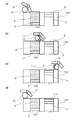
ここで、材料粉末8の1層目を敷設する工程について図2を用いて説明する。本実施例では、材料粉末8として、例えば粒径が3μm程度の材質SUS316の粉体を用いることを考える。
Here, the process of laying the first layer of the
図2(a)は、供給ステージ2から一定量の材料粉末8を取り出す直前の状態を示している。制御装置600のCPU601は、供給ステージ2の昇降駆動手段(不図示)を制御して、供給ステージ2を一定量、上昇させる。造形エリア101の造形プレート9上に敷設する材料粉末8の量(体積)は、供給ステージ2の上昇量と供給ステージ2の上面の面積によって規定される。
FIG. 2A shows a state immediately before taking out a certain amount of the
本実施例では、供給ステージ2は、例えば、一辺が140mmの正方形形状であるものとする。この供給ステージ2を例えば100μm上昇させることにより1層分の材料粉末8を供給する。供給ステージ2を上昇させた後、不図示の駆動手段を介してスキージ13の先端部分をローラ12の下端より下げた状態で供給ステージ2上を移動させる。これにより、スキージ13により一定量の材料粉末8を造形ステージ3側に移動させることができる。
In this embodiment, the
このスキージ13による材料粉末8の造形ステージ3側への移動に先立って、制御装置600のCPU601は、不図示の昇降駆動手段を介して造形ステージ3を一定量下降させ、材料粉末8を敷設するスペースを形成する。本実施例では、造形ステージ3および造形プレート9は、例えば1辺が140mmの正方形であり、この段階では、造形ステージ3の下降量は70μm程度に制御する。
Prior to the movement of the
図2(a)〜(b)は、供給ステージ2より一定量だけ材料粉末8を造形ステージ3側に移動させる様子を示している。この時、制御装置600のCPU601は、粉敷きユニット4のスキージ13と回転ローラ12が同期的に不図示の駆動手段によって移動させる。図2(a)〜(b)の粉敷きユニット4の往路では、特にスキージ13の先端を回転ローラ12の下端より上昇させた揺動姿勢とすることにより、造形ステージ3の上部はローラ12で粉敷きができる状態に制御される。また、図2(a)〜(b)へと粉敷きユニット4を移動させる時、回転ローラ12が造形ステージ3の上部を移動している間、例えば図2(b)の矢印に示すようにローラ12の下端部が進行方向と同方向になるように回転駆動する。これにより、造形エリア101(ステージ3の上部)で、材料粉末8を馴らしながら敷設する。
FIGS. 2A to 2B show how the
なお、造形プレート9の面粗さが粗すぎると薄層の表面に粗さ形状が転写されてしまい、また、面粗さが良すぎると材料粉末8が綺麗に敷けなくなる。本実施例の条件では、材料粉末8が敷かれる造形プレート9の面粗さは、Ra0.7〜3.0μmの範囲であれば綺麗に粉敷きを行えることが判明している。なお、造形プレート9の面粗さは、使用する材料粉末8の種類、造形する薄層の厚みに合わせて変更してよい。
If the surface roughness of the
図2(c)は、造形ステージ3の上部、つまり造形プレート9の上部に材料粉末8を敷いた後の状態を示している。この状態で、造形ステージ3の下降量分だけ、造形プレート9の上部に材料粉末8を敷くことができている。本実施例では、造形ステージ3の下降量である70μm厚みの薄層が敷かれている。ここから、材料粉末8の薄層の密度を向上させる圧縮工程を行う。まず、材料粉末8を敷く時の下降量より少ない量だけ造形ステージ3を上昇させる。本実施例では、造形ステージ3を40μm上昇させる。
FIG. 2C shows a state after the
そして、制御装置600のCPU601は、回転ローラ12を造形ステージ3の上部を例えば上記とは逆方向から移動させる。この回転ローラ12が造形ステージ3の上部を移動中は、例えば図2(c)の矢印に示すように回転ローラ12の下端部が進行方向と同方向になるように回転させることにより材料粉末8を圧縮する。
Then, the
図2(d)は、造形ステージ3の上部での材料粉末8の圧縮を終えて、ローラ12を初期位置に復帰させた状態を示している。この状態において、造形プレート9の上部に敷かれた材料粉末8は、造形ステージ3の下降量分だけ粉末が敷かれていた状態から、圧縮工程時の造形ステージ3の上昇分だけ圧縮されて密度が向上している。
FIG. 2D shows a state in which the
本実施例では、70μmに敷いた材料粉末層を40μm分圧縮させて、30μmの材料粉末層を形成している。このような圧縮工程を行い、材料粉末8の薄層の密度を制御することにより、造形する造形物10(図1)の物性を所望に調節することができる。ただし、上記の圧縮工程は必ずしも行う必要は無く、造形物10の物性値が材料粉末8を高密度に敷く必要が無い場合は、圧縮工程の造形ステージ3の上昇を行わないことで圧縮工程を省略しても良い。その場合、本実施例の制御条件では、圧縮工程時の造形ステージ3を40μm上昇させる工程を無くし、その分、粉敷き前の造形ステージ3の下降量を70μmから30μmに変更すれば同じ厚みの材料粉末層を敷設できる。
In this embodiment, the material powder layer laid at 70 μm is compressed by 40 μm to form a material powder layer of 30 μm. By performing such a compression step and controlling the density of the thin layer of the
以上のようにして、造形ステージ3の上部、つまり造形プレート9の上部に材料粉末8の1層目を敷設することができる。
As described above, the first layer of the
さらに、図1の造形プレート9の上部に材料粉末8の層を敷設した後のレーザ照射(固化)工程について説明する。制御装置600のCPU601は、上記のように敷設した材料粉末層の所定箇所に、造形レーザユニット5によりレーザビーム14を照射させ、材料粉末8を溶融または焼結させて固化層とし造形物10を形成する。当然ながら、材料粉末層に対するレーザビーム14の照射範囲は、造形中の造形物10の当該断面に対応する形状に相当する範囲に制御する。
Further, a laser irradiation (solidification) step after laying a layer of the
そして、上述の粉敷き工程と、レーザビーム照射工程とを繰り返し、実行し、造形物10が所定の形状となるまで造形を行う。粉敷き工程時に、造形ステージ3の上部に載りきらない材料粉末8は、材料粉末回収ユニット6に蹴り落し、材料粉末回収ユニット6に蓄積させる。
Then, the above-mentioned powder laying step and the laser beam irradiation step are repeated and executed until the modeled object 10 has a predetermined shape. During the powder laying process, the
造形物10の最終層まで粉敷き工程と、レーザビーム照射工程とを繰り返し、造形物10が所期の形状に到達すると、造形ステージ3を上昇させて造形物10の周囲に付着している(未固化の)材料粉末8の清掃を行う。この清掃工程は、真空中では材料粉末8の吸引が行えないので、真空環境の場合は材料粉末8の急激な変質の生じる限界酸素濃度以下となるように酸素濃度を調整した気体環境に置換した後に実行する。この清掃工程は、一般に作業者が手動操作によって行うが、別途配置したロボット装置などによって行ってもよく、その形態は特に本発明を限定するものではない。この(未固化の)材料粉末8の清掃工程造形チャンバ15の内部を真空または各気体環境から大気環境に置換し、造形物10を取り出す。以上のようにして、3次元造形物(造形物10)を製造することができる。
The powder laying step and the laser beam irradiation step are repeated until the final layer of the modeled object 10, and when the modeled object 10 reaches the desired shape, the
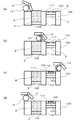
ここで、特に、造形精度を高めるため、粉末の粒径を10μm以下、1層分の薄層の厚みを30μm以下にしている場合において、2層目以降の粉敷き工程で発生しがちな現象について、図3を用いてさらに詳細に説明する。 Here, in particular, when the particle size of the powder is 10 μm or less and the thickness of the thin layer for one layer is 30 μm or less in order to improve the molding accuracy, a phenomenon that tends to occur in the powder laying process of the second and subsequent layers. Will be described in more detail with reference to FIG.
図3(a)は、2層目での供給ステージ2から一定量の材料粉末8を取り出す直前の状態を示している。2層目でも1層目と同様に、制御装置600のCPU601は、供給ステージ2を一定量上昇させることで、上昇量と供給ステージ2の受け面積分の材料粉末8を供給させる。そして、スキージ13の先端部分をローラ12の下端より下降させた状態で供給ステージ2上を移動させる。このような動作によって、スキージ13により一定量だけ材料粉末8を造形ステージ3側に移動させる。図3(b)は、2層目での供給ステージ2より一定量だけ材料粉末8を造形ステージ3側に移動させた後の状態を示している。2層目でも1層目と同様に、造形ステージ3を一定量下げて材料粉末8を敷くスペースを形成している。スキージ13の先端をローラ12の下端より上昇させることで、造形ステージ3の上部はローラ12で粉敷きができる状態にしている。
FIG. 3A shows a state immediately before taking out a certain amount of the
制御装置600のCPU601は、ローラ12を造形ステージ3の上部で移動させ、このローラ12の移動中は、図3(b)の矢印に示すようにローラ12の下端部が進行方向と同方向になるように回転させ、材料粉末8を敷設していく。ここで、1層目では、造形ステージ3の上部に設置された造形プレート9の表面に材料粉末8を敷設したが、2層目では1層目に敷かれた材料粉末8および、レーザ照射により造形された造形物10の表面に材料粉末8を敷設することになる。
The
ここで、図3(c)は、造形ステージ3の上部において、レーザ照射により造形された造形物10の表面と、造形物10の周囲の1層目として敷設された(未固化の)材料粉末の上に材料粉末8を敷いた後の状態を示している。
Here, FIG. 3C shows a (unsolidified) material powder laid on the surface of the modeled object 10 formed by laser irradiation and as the first layer around the modeled object 10 at the upper part of the
このように、1層前に敷設された(未固化)材料粉末8の上部に新たな材料粉末8を敷くことに特に困難性はない。しかしながら、1層目に造形した造形物10の上部は面粗さが良好すぎるために綺麗に材料粉末8を敷けない現象が発生することがある。
As described above, there is no particular difficulty in laying the
上記のようにして造形ステージ3の上部に材料粉末8を供給した後、例えば1層目と同様に材料粉末8の薄層の密度を向上させる圧縮工程を行う。まず、制御装置600のCPU601は、材料粉末8を敷く時の下降量より少ない量だけ造形ステージ3を上昇させる。そして、ローラ12を造形ステージ3の上部を粉敷き時の逆方向から移動させ、ローラ12が造形ステージ3の上部を移動中は、図3(c)の矢印に示すようにローラ12の下端部が進行方向と同方向になるように回転させることで、材料粉末8を圧縮していく。
After the
図3(d)は、ローラ12が造形ステージ3の上部での材料粉末8の圧縮を終えて、初期位置に戻った状態を示している。このように、圧縮工程を終えた後も、図3(d)に示すように、1層目に造形した造形物10の上部には綺麗(均一)に材料粉末8を敷けていない状態が残ることがある。
FIG. 3D shows a state in which the
このため、結果として、1層目に造形した造形物10の上部では、敷設された材料粉末8の量が少なくなってしまうことがある。この場合、レーザ照射工程において、1層目の造形と同じレーザビーム14の照射出力(照射強度)を用いると、2層目の材料粉末8に単位体積当たり多くの熱量が加わり、この部位で造形物10の物性値が変化してしまう可能性がある。
Therefore, as a result, the amount of the laid
ここで、綺麗(均一)に敷設されていない状態の材料粉末層を輻射加熱し、固化させると、その表面の粗さは粗い状態で造形される。このため、綺麗に材料粉末8を敷けていない状態の薄層の造形面上は綺麗に材料粉末8を敷くことができる。つまり、造形物10の上部に材料粉末8を綺麗に敷けない層は1層毎に現れ、綺麗に敷ける層と綺麗に敷けない層が交互に繰り返される。
Here, when the material powder layer in a state where it is not laid cleanly (uniformly) is radiantly heated and solidified, the surface roughness thereof is formed in a rough state. Therefore, the
即ち、上述のように特に材料粉末が細粒であって、敷設する材料粉末層が薄い場合、良好(例えば均一性よく)に敷設された材料粉末層は、交互に現れることになる。例えば、造形プレート9が材料粉末の敷設に適した表面特性であれば1層目の材料粉末層は良好(均一)に敷設でき、2層目は逆に均一性に欠ける材料粉末層となる。そして、3層目は再度、良好(均一)に敷設された材料粉末層となる。以後、奇数番目の層に良好(均一)に敷設された材料粉末層が、また、偶数番目の層に均一性に欠ける材料粉末層が交互に現れることになる。また、もし、造形プレート9の上面が鏡面加工されているなど、材料粉末の敷設に適していない表面特性である場合には、上記の奇数番目と偶数番目に現れる材料粉末層の敷設特性(敷設結果ないしは表面状態)は上記と逆になる。
That is, as described above, especially when the material powder is fine and the material powder layer to be laid is thin, the material powder layers laid well (for example, with good uniformity) appear alternately. For example, if the
そして、良好(均一)に敷設された材料粉末層と、敷設状態が良好(均一)ではなく、敷設総量の少ない材料粉末層と、でこれらを固化させるのに同じレーザビーム14の照射出力(照射強度)を採用するのは適切でなない。この場合には、敷設総量の少ない良好(均一)ではない材料粉末層で過大な輻射加熱が行われ、形成された固化層の位置で造形物10の物性値が変化してしまう。
Then, the irradiation output (irradiation) of the
そこで、本実施例では、制御装置600に、交互に現れる良好(均一)に敷設された材料粉末層と、敷設状態が良好(均一)ではなく、敷設総量の少ない材料粉末層とで、それぞれに適した照射出力(照射強度)となるよう造形レーザユニット5を制御させる。
Therefore, in this embodiment, the
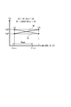
例えば、図6は、上述のように特に材料粉末が細粒であって、敷設する材料粉末層が薄い場合、下層から順に敷設(固化)される材料粉末層Nの各層の均一性U(あるいは敷設された粉末量)の変化を示している。また、図6において、Lpは、各々の材料粉末層nの均一性U(ないし粉末量)に適した造形レーザユニット5で照射すべきレーザビーム14の照射出力(照射強度)に相当する。そして、この場合、均一性Uの良好な(充分な粉末量の敷設された)材料粉末層(図6のN=1,3,5…)の固化では、規定値に相当する照射出力値(大)を適用する。一方、均一性Uに欠ける(敷設された粉末量の少ない)材料粉末層(図6のN=2,4,6…)の固化では、規定値より減力した照射出力値(小)を適用する。このような制御により、全体に渡って物性値の均一な造形物10を造形することができる。
For example, FIG. 6 shows the uniformity U (or the uniformity U) of each layer of the material powder layer N to be laid (solidified) in order from the lower layer, especially when the material powder is fine-grained and the material powder layer to be laid is thin as described above. It shows the change in the amount of powder laid). Further, in FIG. 6, Lp corresponds to the irradiation output (irradiation intensity) of the
そこで、本実施例では、より具体的には次のような造形制御を行う。 Therefore, in this embodiment, more specifically, the following modeling control is performed.
(1)表面状態測定装置(例えばカメラ7)を用い、材料粉末を敷設する敷設面(造形プレート9または固化済みの造形物10の表面)の表面状態を測定する。そして、測定した表面状態に応じて、その敷設面に敷設する材料粉末の固化に適用すべきエネルギービーム(レーザビーム)の照射出力を制御する。
(1) Using a surface condition measuring device (for example, a camera 7), the surface condition of the laying surface (the surface of the
(2)または、表面状態測定装置(例えばカメラ7)を用い、敷設済みの材料粉末の表面状態を測定する。そして、測定した表面状態に応じて、当該の材料粉末層の固化に適用すべきエネルギービーム(レーザビーム)の照射出力を制御する。 (2) Alternatively, the surface condition of the laid material powder is measured using a surface condition measuring device (for example, camera 7). Then, the irradiation output of the energy beam (laser beam) to be applied to the solidification of the material powder layer is controlled according to the measured surface condition.
(3)材料粉末層の敷設の良好度(均一性)が交互に変化することを利用する。例えば、それまでに敷設した、あるいは、エネルギービームの照射により固化させた固化層の層数の偶奇性情報に基づき、材料粉末層を固化させるエネルギービーム(レーザビーム)の照射出力を制御する。例えば、それまでの固化層の層数が0(偶数)である、つまり、造形プレート9上に良好に敷設された1層目の材料粉末層の固化では、規定のエネルギービーム(レーザビーム)の照射出力を用いる。一方、それまでの固化層の層数が1(奇数)である、つまり、1層目の材料粉末層から固化させた1層目の固化層上に敷設された、良好(均一)ではなく、敷設総量の少ない材料粉末層では、照射出力を規定値よりも減力した(小さい)値とする。
(3) Utilize the fact that the goodness (uniformity) of laying the material powder layer changes alternately. For example, the irradiation output of the energy beam (laser beam) that solidifies the material powder layer is controlled based on the evenness information of the number of solidified layers that have been laid or solidified by the irradiation of the energy beam. For example, the number of solidified layers up to that point is 0 (even), that is, in the solidification of the first material powder layer laid well on the
(4)あるいは、材料粉末層の敷設の良好度(均一性)が交互に変化することを利用すべく、規定のエネルギービーム(レーザビーム)の照射出力値(大)と、それよりも減力した照射出力値(小)を用意し、これらを交互に適用する。例えば、敷設した各材料粉末層の固化において、それぞれ…照射出力値(大)、照射出力値(小)、照射出力値(大)…の順でエネルギービーム(レーザビーム)の照射出力値を適用する。この場合、例えば、当該の料粉末層の固化において用いる照射出力値(大または小)は、直前の料粉末層の固化で用いた照射出力値(小または大)に応じて選択することができる。この場合、例えば、造形プレート9上に敷設された1層目の材料粉末層の固化に用いる照射出力値(大または小のいずれか)さえ特定しておけば、以後、2層目以降の固化層の形成に用いる照射出力値(小または大)を適宜選択することができる。
(4) Alternatively, in order to take advantage of the fact that the goodness (uniformity) of laying the material powder layer changes alternately, the irradiation output value (large) of the specified energy beam (laser beam) and the reduced power are reduced. Prepare the irradiation output value (small), and apply these alternately. For example, in the solidification of each material powder layer laid, the irradiation output value of the energy beam (laser beam) is applied in the order of ... irradiation output value (large), irradiation output value (small), irradiation output value (large) ... To do. In this case, for example, the irradiation output value (large or small) used in the solidification of the powder layer can be selected according to the irradiation output value (small or large) used in the solidification of the immediately preceding powder layer. .. In this case, for example, as long as the irradiation output value (either large or small) used for solidifying the first layer of the material powder layer laid on the
次に、上記の造形制御(1)〜(4)のより具体的な構成例につき、順次説明する。 Next, more specific configuration examples of the above-mentioned modeling controls (1) to (4) will be sequentially described.
図1の造形装置(3次元造形物の製造装置)には、造形ステージ3の上部を撮像できるカメラ7を配置している。このカメラ7を上記の造形制御(1)または(2)に用いることができる。このカメラ7は、材料粉末の敷設前の敷設面(造形プレート9または固化済みの造形物10の表面)、または、敷設済みの材料粉末8の表面状態を測定する表面状態測定装置として用いることができる。
A
例えば、制御装置600のCPU601は、カメラ7の撮影画像を解析し、敷設面を撮影している場合は敷設面の表面状態が、材料粉末を良好な均一性(U)で敷設できる状態(敷設面自体の表面状態は均一性(U)の比較的低い状態)か否かを判定できる。また、敷設済みの材料粉末8の表面を撮影している場合は、材料粉末8が良好な均一性(U)で敷設されているか否かを判定できる。
For example, the
例えば、制御装置600のCPU601は、粉敷き工程(および圧縮工程)の前に、材料粉末を敷設する敷設面(造形プレート9または固化済みの造形物10の表面)をカメラ7で撮像させる。または、粉敷き工程(および圧縮工程)の後で、敷設(および圧縮)済みの材料粉末層をカメラ7で撮像させる。
For example, the
そして、敷設面の表面を撮影している場合は、材料粉末を良好な均一性(U)で敷設できる状態であれば、その敷設面に敷設する材料粉末層を固化させるレーザビームの照射出力としては、規定の照射出力値(大、または規定値)を採用する。逆に、敷設面自体の表面状態の均一性(U)が比較的高い状態であれば、その上に敷設される材料粉末の敷設状態は均一性(U)が比較的低くなる。この場合には、その上に敷設される材料粉末の固化には、規定の照射出力値よりも減力した照射出力値(小)を採用する。 Then, when the surface of the laying surface is photographed, if the material powder can be laid with good uniformity (U), the irradiation output of the laser beam that solidifies the material powder layer to be laid on the laying surface is used. Adopts the specified irradiation output value (large or specified value). On the contrary, if the surface condition (U) of the laying surface itself is relatively high, the uniformity (U) of the material powder laid on the surface is relatively low. In this case, an irradiation output value (small) that is weaker than the specified irradiation output value is adopted for solidifying the material powder laid on the material powder.
一方、敷設済みの材料粉末8の表面を撮影している場合は、当該の材料粉末層を固化させるレーザビームの照射出力としては、表面状態の良好な材料粉末層については、規定の照射出力値(大、または規定値)を採用する。逆に、表面状態の良好ではない材料粉末層については、規定の照射出力値よりも減力した照射出力値(小)を採用する。
On the other hand, when the surface of the laid
制御装置600のCPU601にこのような照射出力制御工程を実行させることにより、レーザビーム14を照射して材料粉末8を溶融または焼結させた時に、材料粉末8に加わる入熱量を粉敷き状態に合わせた熱量に制御することができる。これにより、想定通りの造形物10の物性値、特に各造形層の物性値が均一な、良好な品質の造形物10を造形することができる。
By causing the
なお、表面状態測定装置としてのカメラ7は、非接触の変位計や形状計測計、あるいは、表面粗さを計測できるような白色干渉計やレーザ顕微鏡などの計測器に置換してもよい。また、カメラ7などの表面状態測定装置は、必ずしも図1に例示したような位置(メインフレーム1)に固定的に配置しなくてもよい。例えば、表面状態測定装置は、不図示のロボットアームや、XYステージなどの移動手段によって移動可能に構成し、造形ステージ3の上部を走査しながら計測する表面状態測定形態を採用してもよい。あるいは、このように表面状態測定装置を移動させる移動手段は、粉敷きユニット4を移動させる駆動軸を利用して構成してもよい。
The
一方、上記の造形制御(3)では、材料粉末層の敷設の良好度(均一性)が交互に変化することを利用する。例えば、それまでに敷設した材料粉末層、あるいはそれまでにエネルギービームの照射により固化させた固化層の層数の偶奇性情報に基づき、材料粉末層を固化させるエネルギービーム(レーザビーム)の照射出力を制御する。 On the other hand, in the above-mentioned modeling control (3), it is utilized that the goodness (uniformity) of laying the material powder layer changes alternately. For example, the irradiation output of the energy beam (laser beam) that solidifies the material powder layer based on the evenness information of the number of layers of the material powder layer laid up to that point or the solidified layer solidified by the irradiation of the energy beam. To control.
上述のように、表面粗さを適切に加工している造形プレート9の上部は材料粉末8を綺麗(均一)に敷設でき、その次の例えば造形物10の上部などの層は綺麗(均一)に敷設されない可能性がある。即ち綺麗(均一)に敷ける材料粉末層とそうではない層が交互に繰り返される傾向がある。そこで、造形制御(3)では、例えばそれまでに(敷設した、あるいは)エネルギービームの照射により固化させた固化層の層数(n)の偶奇性情報を利用することが考えられる。
As described above, the
例えば、制御装置600のCPU601は、レジスタやRAM603上などに配置したカウンタなどを用いて造形プレート9から何層目を造形するのかを計数し、その数を認識できる。このカウンタが、例えばそれまでに固化させた固化層の数(n:整数値)を計数するものとすれば、このnの数値の偶奇性情報を利用することができる。なお、ここでいうそれまでに(敷設した、あるいは)エネルギービームの照射により固化させた固化層の層数(n)は、図6では、Nの値から1を減じた値に相当する。
For example, the
例えば、CPU601のような計算手段は、整数(自然数)が偶数か奇数かは、2で割ったときの剰余の有無により判定することができる。このような判定関数は、例えばmod2(n)のような記法によって記述してもよい。例えば、mod2(n)=0の場合、nは偶数、mod2(n)=1の場合、nは奇数である。 For example, a calculation means such as CPU601 can determine whether an integer (natural number) is an even number or an odd number based on the presence or absence of a remainder when divided by two. Such a determination function may be described by a notation such as mod2 (n). For example, when mod2 (n) = 0, n is an even number, and when mod2 (n) = 1, n is an odd number.
ここで、もし、造形プレート9(の上面)が材料粉末の敷設に適した表面状態であれば、1層目の材料粉末を敷設した直後では、それまでに(敷設した、あるいは)固化させた固化層の数(n)はn=0、上記の判定関数の出力はmod2(n)=0となる。そこで、上記の交互に現れる材料粉末層の表面状態を考慮すると、判定関数がmod2(n)=0となる表面状態の良好な材料粉末層については、固化に用いるレーザビームの照射出力は、規定の照射出力値(大)とする。また、判定関数がmod2(n)=1となる表面状態の良好ではない(敷設量の少ない)材料粉末層については、規定よりも減力した照射出力値(小)とする。 Here, if the modeling plate 9 (upper surface) has a surface condition suitable for laying the material powder, immediately after the first layer of the material powder is laid, it has been (laid or) solidified by then. The number of solidified layers (n) is n = 0, and the output of the above determination function is mod2 (n) = 0. Therefore, considering the surface condition of the material powder layer that appears alternately, the irradiation output of the laser beam used for solidification is specified for the material powder layer having a good surface condition in which the determination function is mod2 (n) = 0. Irradiation output value (large) of. Further, for the material powder layer whose surface condition is not good (the amount of laying is small) in which the determination function is mod2 (n) = 1, the irradiation output value (small) is set to be smaller than the specified value.
このように造形制御(3)では、良好(均一)、あるいは良好(均一)ではない材料粉末層の表面状態(あるいは敷設された粉末量)が交互に現れる特性を利用する。そして、レーザビーム14を照射して材料粉末8を固化させる時の入熱量(輻射熱量)を材料粉末層の敷設状態(ないしは敷設量)に適合した熱量に制御することができる。
As described above, in the modeling control (3), the characteristic that the surface state (or the amount of laid powder) of the material powder layer which is not good (uniform) or good (uniform) appears alternately is utilized. Then, the amount of heat input (radiant heat amount) when the
従って、この造形制御(3)によっても、材料粉末8に加わる入熱量を粉敷き状態に合わせた熱量に制御することができる。従って、上記の造形制御(3)によっても、想定通りの造形物10の物性値を有する、特に各造形層の物性値が均一な、良好な品質の造形物10を造形することができる。
Therefore, also by this modeling control (3), the amount of heat input to the
なお、上記の造形制御(3)は、造形プレート9(の上面)の表面状態、ないしは、その直上に1層目として敷設される材料粉末層の敷設状態さえ特定できれば実施可能である。即ち、例えばそれまでに(敷設した、あるいは)固化させた固化層の数(n)の偶奇性(mod2(n)が1/0のいずれであるか)を利用して、当該の材料粉末層の固化に用いるレーザビームの照射出力(大、または小)を交互に選択することができる。このため、上記の造形制御(3)は、表面状態測定装置としてカメラ7のような手段を配置していない造形装置においても、簡単安価に実施することができる。
The above-mentioned modeling control (3) can be carried out as long as the surface state of the modeling plate 9 (upper surface) or the laying state of the material powder layer laid directly above the
また、上記の造形制御(4)も材料粉末層の敷設の良好度(均一性)が交互に変化することを利用するものである。この造形制御(4)では、規定の照射出力値(大)と、それよりも減力した照射出力値(小)を交互に用いるよう制御する。例えば、制御装置600のCPU601は、造形レーザユニット5を制御する照射出力値を決定する時、前回の材料粉末層の固化で用いた照射出力値(大または小)に応じて、今回の材料粉末層について用いる照射出力値(小または大)を選択すればよい。
Further, the above-mentioned modeling control (4) also utilizes the fact that the goodness (uniformity) of laying the material powder layer changes alternately. In this modeling control (4), the specified irradiation output value (large) and the irradiation output value (small) reduced from the specified irradiation output value (small) are alternately used. For example, when the
また、この造形制御(4)も、造形レーザユニット5の出力するレーザビーム14の大、または小の照射出力値を交互に適用する制御である。このため、この造形制御(4)も、造形プレート9(の上面)の表面状態、ないしは、その直上に1層目として敷設される材料粉末層の敷設状態(ないしこの層に適用すべき照射出力値)さえ特定できれば実施可能である。
Further, this modeling control (4) is also a control in which large or small irradiation output values of the
そして上記の造形制御(4)によっても、材料粉末8に加わる入熱量を粉敷き状態に合わせた熱量に制御することができる。従って、上記の造形制御(4)によっても、想定通りの造形物10の物性値を有する、特に各造形層の物性値が均一な、良好な品質の造形物10を造形することができる。
Then, also by the above-mentioned modeling control (4), the amount of heat input to the
ここで、図5に、図1の造形装置において、制御装置600のCPU601で実行させる上記の造形制御(1)〜(4)を考慮した3次元造形物の製造過程全体の制御手順の一例を例示する。図5に示した制御手順は、3D造形物の製造方法、あるいは3D造形物を造形する造形装置(図1)の制御方法に相当し、CPU601の制御プログラムとして、例えばROM602(あるいは不図示の外部記憶装置)に格納しておくことができる。
Here, FIG. 5 shows an example of a control procedure for the entire manufacturing process of the three-dimensional modeled object in consideration of the above-mentioned modeling controls (1) to (4) executed by the
図5のステップS10において、制御装置600のCPU601は、上記の例えばそれまでに(敷設ないし)固化させた固化層の数(n:整数値)を計数するカウンタ(n)を0に初期化する。なお、このカウンタ(n)は、表面状態測定装置としてカメラ7のような手段を用いない場合には必ずしも必要がなく、その場合にはこのステップS10は省略してもよい。
In step S10 of FIG. 5, the
続いて、ステップS20では、CPU601は、インターフェース604を介して外部装置から予め用意された造形物の3次元モデルデータ(3DCAD、3DCGデータなど)を入力(受信)する。
Subsequently, in step S20, the
続いて、ステップS30では、入力した3次元モデルデータを水平断面の積層データに分解し、さらに各層に対応する層データ、即ち各造形層のスキャン軌跡のデータを生成する。また、ステップS30において、CPU601は、必要に応じて、当該の造形層の軌跡データに基づき、レーザ走査系例えばガルバノスキャナの駆動データに変換する。なお、造形レーザユニット5の走査系は上述の構成に限定されるものではない。例えばガルバノスキャナなどの揺動走査系に限定されることなく、必要に応じてポリゴンミラーなどの回転走査系を用いることが考えられる。また、本実施形態では、エネルギービームとしてレーザビーム(L)を考えたが、材料粉末8の輻射加熱に電子ビームなどの他のエネルギービームを用いる場合には、その発生源や、走査系は当業者において適宜変更して構わない。
Subsequently, in step S30, the input three-dimensional model data is decomposed into the laminated data of the horizontal cross section, and the layer data corresponding to each layer, that is, the scan locus data of each modeling layer is generated. Further, in step S30, the
続いて、ステップS40において、CPU601は、カメラ7による撮影、並びに、上述の図2(あるいは図3)で説明した材料粉末層の敷設(および圧縮)、および処理を行わせる。上記の造形制御(1)の場合は、カメラ7によって、材料粉末の敷設前の敷設面(造形プレート9または固化済みの造形物10の表面)を撮像させる。また、造形制御(2)の場合は、カメラ7によって、上記敷設面上に敷設済みとなっている材料粉末8の表面を撮影させる。
Subsequently, in step S40, the
そして、CPU601は、インターフェース605を介してカメラ7から取得した測定情報に基づき、敷設した材料粉末層の表面状態に関する情報を取得する(測定情報取得工程)。なお、このインターフェース605を介してカメラ7から測定情報を取得する測定情報取得工程は下記のステップS50に含まれていてもよい。
Then, the
ステップS50では、CPU601は、上述の造形制御(1)〜(4)として説明したいずれかの手法を用いて、敷設した材料粉末層の固化のために造形レーザユニット5に与える照射出力値LPn(大、または小)を決定する(照射出力制御工程)。
In step S50, the
ここで、図5のステップS50の枠内には、照射出力値LPn(大、または小)を決定する上記の造形制御(1)〜(4)に相当する疑似関数表現を記入してある。最初のLPn=f(U)は、上記の造形制御(1)または(2)に相当し、表面状態測定装置(カメラ7)で取得した被測定面の表面状態、例えばその均一性(U)に応じて、照射出力値LPn(大、または小)を選択する制御に相当する(測定情報取得工程)。 Here, in the frame of step S50 of FIG. 5, pseudo-function expressions corresponding to the above-mentioned modeling controls (1) to (4) for determining the irradiation output value LPn (large or small) are entered. The first LPn = f (U) corresponds to the above-mentioned modeling control (1) or (2), and the surface state of the surface to be measured acquired by the surface state measuring device (camera 7), for example, its uniformity (U). Corresponds to the control of selecting the irradiation output value LPn (large or small) according to (measurement information acquisition step).
なお、このステップS50における表面状態測定装置(カメラ7)で取得した撮影表面の表面状態に係る情報、例えばその均一性(U)に応じて、照射出力値LPn(大、または小)を決定する制御例については、後で別項を設けてより詳細に説明する。 The irradiation output value LPn (large or small) is determined according to the information related to the surface condition of the imaged surface acquired by the surface condition measuring device (camera 7) in step S50, for example, its uniformity (U). A control example will be described in more detail later with a separate section.
また、2つ目のLPn=g(mod2(n))は、上記の造形制御(2)に相当し、例えばそれまでに(敷設ないし)固化させた固化層の数(n:整数値)の偶奇性情報に基づき、照射出力値LPn(大、または小)を選択する制御に相当する。 The second LPn = g (mod2 (n)) corresponds to the above-mentioned modeling control (2), for example, the number of solidified layers (n: integer value) that have been (laid or) solidified up to that point. It corresponds to the control of selecting the irradiation output value LPn (large or small) based on the evenness information.
また、3つ目のLPn=h(LPn−1)は、上記の造形制御(4)に相当し、前回の材料粉末層の固化で用いた照射出力値(大または小)に応じて、今回の材料粉末層について用いる照射出力値(小または大)を選択する制御に相当する。 Further, the third LPn = h (LPn-1) corresponds to the above-mentioned modeling control (4), and this time, depending on the irradiation output value (large or small) used in the previous solidification of the material powder layer. Corresponds to the control of selecting the irradiation output value (small or large) used for the material powder layer of.
続くステップS60において、CPU601は、ステップS50の上記のいずれかの上記の造形制御(1)〜(4)によって決定した照射出力値(大または小)で造形レーザユニット5を駆動する(照射出力制御工程)。これにより、当該の材料粉末層を溶融ないし焼結させ、固化させる。ステップS70では、造形ステージ3を次の材料粉末層の敷設(および圧縮)に必要な量だけ下降させる。
In the following step S60, the
ステップS80では、造形物10の最終層まで造形を終了した(Y)か否(N)かを判定する。ここで最終層までの造形が終了していない場合には、(必要に応じて)ステップS90でカウンタ(n)を1だけカウントアップしてステップS30に復帰し、上記の処理を繰り返す。 In step S80, it is determined whether or not the modeling is completed up to the final layer of the modeled object 10 (Y) or not (N). Here, if the modeling up to the final layer is not completed, the counter (n) is counted up by 1 in step S90 (if necessary) to return to step S30, and the above processing is repeated.
例えば、図5に示したような制御手順により、図1の造形装置を制御し、本発明の3D造形物の製造方法、あるいは3D造形物を造形する造形装置の制御方法に相当する造形制御を実現することができる。そして、上記構成によれば、上記の造形制御(1)〜(4)に相当するエネルギービームの照射出力値(大または小)決定過程により、想定通りの造形物10の物性値を有する、特に各造形層の物性値が均一な、良好な品質の造形物10を造形することができる。 For example, by the control procedure as shown in FIG. 5, the modeling apparatus of FIG. 1 is controlled, and the modeling control corresponding to the manufacturing method of the 3D modeled object of the present invention or the control method of the modeling device for modeling the 3D modeled object is performed. It can be realized. Then, according to the above configuration, the physical property value of the modeled object 10 as expected is obtained by the process of determining the irradiation output value (large or small) of the energy beam corresponding to the modeling controls (1) to (4), particularly. It is possible to model a modeled object 10 having a uniform physical property value of each modeling layer and having good quality.
<造形制御(1)、(2)における照射出力制御(図5のS50)>
図7に、表面状態測定装置(カメラ7)で取得した撮影表面の表面状態に係る情報、例えばその均一性(U)に応じて選択すべき造形レーザユニット5の照射出力値Lp(大:Lph、または小:Lpl)の関係を示す。
<Irradiation output control in modeling control (1) and (2) (S50 in FIG. 5)>
FIG. 7 shows the irradiation output value Lp (large: Lph) of the
図7において、縦軸は、材料粉末に照射する造形レーザユニット5の照射出力値Lp(大:Lph、または小:Lpl)を、横軸は、撮影表面の表面状態に係る情報、例えばその均一性(U)の尺度に割り当てられている。また、便宜上、BおよびMの各参照符号で示した1次関数的な直線(実際には高次の曲線である可能性がある)は、表面状態測定装置(カメラ7)で取得した撮影表面の表面状態の均一性(U)と、選択すべき照射出力値Lpの関係を示す。
In FIG. 7, the vertical axis represents the irradiation output value Lp (large: Lph or small: Lpl) of the
ここで、特に、Bの直線は、上記造形制御(1)において、撮影した材料粉末の敷設面の表面状態の均一性(U)と選択すべき照射出力値Lpの関係を示している。また、Mの直線は、上記造形制御(2)において、撮影した材料粉末の上面の表面状態の均一性(U)と選択すべき照射出力値Lpの関係を示している。 Here, in particular, the straight line B indicates the relationship between the uniformity (U) of the surface state of the laid surface of the photographed material powder and the irradiation output value Lp to be selected in the above-mentioned modeling control (1). Further, the straight line M indicates the relationship between the uniformity (U) of the surface state of the upper surface of the photographed material powder and the irradiation output value Lp to be selected in the above-mentioned modeling control (2).
ここまでの説明では、材料粉末の敷設面、または材料粉末の上面の表面状態に関して、「均一性(U)」という上位の概念を用いて言及してきたが、実際には(例えばプログラム実装上では)この「均一性(U)」は表面粗さ(Ra値)に対応づけてもよい。例えば、図7中には、敷設面の場合であればその上に良好な「均一性(U)」を持って材料粉末を敷設できるとした、上述の表面粗さ(Ra値)の範囲Raw(3.0μm〜0.7μm)を図示してある。 In the explanation so far, the surface condition of the laying surface of the material powder or the upper surface of the material powder has been referred to by using the higher concept of "uniformity (U)", but in reality (for example, in program implementation). ) This "uniformity (U)" may be associated with the surface roughness (Ra value). For example, in FIG. 7, in the case of a laying surface, the material powder can be laid with good "uniformity (U)" on the laying surface, which is the above-mentioned range of surface roughness (Ra value) Raw. (3.0 μm to 0.7 μm) is shown in the figure.
図7のBの直線は、上記造形制御(1)において採用すべき表面状態と照射出力値の関係を示している。即ち、図7のBのように、撮影した材料粉末の敷設面の表面状態の均一性(U)が比較的低い場合は、CPU601は、その後敷設される材料粉末の固化には、照射出力値(大:Lph)の値を用いる。この表面状態の均一性(U)は比較的低い場合は、材料粉末の敷設面に良好な「均一性(U)」を持って材料粉末を敷設できるRawの範囲に相当する。一方、図7の右方において、撮影した材料粉末の敷設面において、表面粗さがRawの範囲を超えて、表面粗さが小さく、面精度が高くなっている場合には、CPU601は、敷設される材料粉末の固化には、照射出力値(小:Lpl)の値を採用する。
The straight line B in FIG. 7 shows the relationship between the surface state and the irradiation output value to be adopted in the modeling control (1). That is, when the uniformity (U) of the surface state of the laid surface of the photographed material powder is relatively low as shown in B of FIG. 7, the
一方、図7のMの直線は、上記造形制御(2)において採用すべき表面状態と照射出力値の関係を示している。即ち、図7のBのように、撮影した材料粉末の上面の表面粗さが上記のRawの範囲なら、敷設した材料粉末の表面状態の均一性(U)は比較的低いことを示す。この場合には、敷設されている材料粉末には比較的まばらな領域が含まれ、結果として敷設されている材料粉末の敷設量が小さい、と判断できる。このため、照射出力値(大:Lph)の値を用いると、輻射熱量が過大となり、望ましくない物性変化を生じる可能性がある。そこで、撮影した材料粉末の上面の表面粗さが上記のRawの範囲なら、CPU601は、この撮影した材料粉末の固化には、照射出力値(小:Lpl)の値を採用する。一方、図7の右方において、撮影した材料粉末の上面の表面粗さがRawの範囲を超えて、表面粗さが小さく、より面精度が高くなっている場合には、敷設した材料粉末の表面状態の均一性(U)が高く、良好な敷設状態である。この場合には、敷設されている材料粉末の敷設量は規定通り充分あるため、CPU601は、敷設される材料粉末の固化には、照射出力値(大:Lph)の値を用いる。
On the other hand, the straight line M in FIG. 7 shows the relationship between the surface state and the irradiation output value to be adopted in the above-mentioned modeling control (2). That is, as shown in FIG. 7B, if the surface roughness of the upper surface of the photographed material powder is within the above Raw range, the uniformity (U) of the surface state of the laid material powder is relatively low. In this case, it can be determined that the laid material powder contains relatively sparse areas, and as a result, the laid amount of the laid material powder is small. Therefore, if the value of the irradiation output value (large: Lph) is used, the amount of radiant heat becomes excessive, which may cause an undesired change in physical properties. Therefore, if the surface roughness of the upper surface of the photographed material powder is within the above Raw range, the
このように、造形制御(1)および(2)では、撮影した被測定面の表面状態の均一性(U)に係る物性量、例えば表面粗さと照射出力値の大小関係が逆になる。しかし、これらの制御の目的は同じで、均一に、充分な敷設量で敷設される(敷設された)材料粉末層の固化では照射出力値を大(Lph)とし、逆に均一を欠き敷設量が充分ではない材料粉末層の固化では照射出力値を小(Lpl)とすることである。なお、造形制御(1)および(2)においても、結果として、良好な均一性(U)で敷設、固化された材料粉末(固化)層の、次の層の敷設では、面精度の高さから敷設特性(均一度や敷設量)が低下する、という偶奇(交互)性が作用する。このため、実際の制御結果としては、エネルギービームの照射出力値の制御結果は、造形制御(3)、(4)の場合とほぼ同様の層交互のパターンで実行されることになる。 As described above, in the modeling control (1) and (2), the magnitude relation between the physical property amount related to the uniformity (U) of the surface state of the photographed surface to be measured, for example, the surface roughness and the irradiation output value is reversed. However, the purpose of these controls is the same, and the irradiation output value is set to a large value (Lph) in the solidification of the material powder layer that is laid (laid) uniformly and with a sufficient laying amount, and conversely, the laying amount lacks uniformity. However, in the solidification of the material powder layer, the irradiation output value is set to a small value (Lpl). In addition, also in the modeling control (1) and (2), as a result, the surface accuracy is high in the laying of the next layer of the material powder (solidified) layer laid and solidified with good uniformity (U). Since the laying characteristics (uniformity and laying amount) are reduced, the even-oddness (alternate) acts. Therefore, as an actual control result, the control result of the irradiation output value of the energy beam is executed in a layer alternating pattern substantially similar to the case of the modeling control (3) and (4).
なお、カメラ7のかわりに表面状態測定装置として白色干渉計やレーザ顕微鏡のような装置を用いるなら、これらの装置は表面粗さの値を出力可能であるから、以上に示した表面粗さ〜照射出力値の関係づけを利用して制御を行うことができる。
If a device such as a white interferometer or a laser microscope is used as the surface condition measuring device instead of the
一方、表面状態測定装置として、(一般的なデジタルカメラのような)カメラ7を用いる場合には、撮影した被測定面の表面状態の均一性(U)に係る物性量として、他の測定量を利用できる可能性がある。例えば、図7の横軸のUに括弧書きで付記したDおよびFは、撮影画像の「濃度」(の分布情報)(D)や「空間周波数」(F)の値を意図したものである。これらの値は当然ながら、被測定面の粒状度や面精度、表面粗さなどに対応する表面状態の均一性(U)の尺度として考えてよい。 On the other hand, when a camera 7 (like a general digital camera) is used as the surface condition measuring device, another measured quantity is used as a physical property quantity related to the uniformity (U) of the surface condition of the surface to be measured. May be available. For example, D and F added in parentheses to U on the horizontal axis of FIG. 7 are intended to be the values of "density" (distribution information) (D) and "spatial frequency" (F) of the captured image. .. As a matter of course, these values can be considered as a measure of the uniformity (U) of the surface state corresponding to the granularity, surface accuracy, surface roughness, etc. of the surface to be measured.
従って、CPU601はカメラ7の撮影画像から、その画像の「濃度(濃度平均値や濃度分布)」(D)、「空間周波数」(F)の値を取得する。そして、予め図7のB、Mのような波形で、「濃度(濃度平均値や濃度分布)」(D)、「空間周波数」(F)の値と、照射出力値を関係づけたデータテーブルを用意しておき、このテーブルを参照して、照射出力値を決定することができる。このようなデータテーブルは、予め実験を行って得た測定結果に基づき作成することができる。即ち、プログラム実装上は、カメラ7の撮影画像から取得した画像の「濃度(濃度平均値や濃度分布)」(D)、「空間周波数」(F)の値から直接、照射出力値を決定する造形制御を行ってもよい。この場合には、特に表面粗さなどを出力する機能を有さない(一般的なデジタルカメラのような)カメラ7を用いて、簡単安価に、また高速な処理によって、造形レーザユニット5の照射出力値Lpを決定することができる。
Therefore, the
なお、CPU601は、カメラ7の撮影情報、例えば「濃度(濃度平均値や濃度分布)」(D)、「空間周波数」(F)の値から、表面粗さ(図7中のR)や、敷設されている(単位面積あたりの)材料粉末の量(同V)のような特性量を計算してもよい。そして、画像解析に基づき計算した表面粗さ(図7中のR)や、敷設されている(単位面積あたりの)材料粉末の量(同V)を表面状態の均一性(U)の尺度として用いて、造形レーザユニット5の照射出力値Lpを決定してもよい。この場合にも、上記同様のデータテーブルを利用したテーブル演算手法によって、照射出力値を決定できる。なお、採用するカメラ7の仕様や、CPU601が利用する画像処理ライブラリの仕様によっては、上記の「濃度(濃度平均値や濃度分布)」(D)に替えて、「輝度(輝度平均値や輝度分布)」の情報を利用してもよい。
It should be noted that the
また、図7に示したような連続性を有する表面状態の均一性(U)と照射出力値の関係をデータテーブルとして用意しておけば、CPU601は、カメラ7の撮影画像中の特定部位に対応するエネルギービームの照射領域の照射出力値を選択することができる。この場合には、CPU601は、造形レーザユニット5のレーザビーム14を走査させる座標系と、カメラ7の撮影フレーム中の座標系を関連づけた同次変換行列のような変換データを用意しておく。そして、カメラ7の撮影フレーム中の特定部位の均一性(U)(あるいは上記の濃度、輝度、空間周波数など)に応じて、その部位に対応する、レーザビーム14の走査座標系におけるスポットで照射すべき照射出力値を選択する。このような制御を行うことにより、1つの材料粉末層中の特定部位ごとに、均一性(U)(あるいは上記の濃度、輝度、空間周波数など)に応じて適切な照射出力値を選択することができる。なお、この場合には、カメラ7の撮影フレーム中の特定部位の均一性(U)(あるいは上記の濃度、輝度、空間周波数など)の評価は、層データ(図5のS30)に応じて、レーザビーム14が走査される部位のみ実行すればよい。これにより、CPU601の演算量を削減できる可能性がある。
Further, if the relationship between the uniformity (U) of the surface state having continuity and the irradiation output value as shown in FIG. 7 is prepared as a data table, the
本発明は、上述の実施形態の1以上の機能を実現するプログラムを、ネットワーク又は記憶媒体を介してシステム又は装置に供給し、そのシステム又は装置のコンピュータにおける1つ以上のプロセッサーがプログラムを読出し実行する処理でも実現可能である。また、1以上の機能を実現する回路(例えば、ASIC)によっても実現可能である。 The present invention supplies a program that realizes one or more functions of the above-described embodiment to a system or device via a network or storage medium, and one or more processors in the computer of the system or device reads and executes the program. It can also be realized by the processing to be performed. It can also be realized by a circuit (for example, ASIC) that realizes one or more functions.
1…メインフレーム、2…供給ステージ、3…造形ステージ、4…粉敷きユニット、5…造形レーザユニット、7…カメラ、8…材料粉末、10…造形物。 1 ... mainframe, 2 ... supply stage, 3 ... modeling stage, 4 ... powder laying unit, 5 ... modeling laser unit, 7 ... camera, 8 ... material powder, 10 ... modeled object.
Claims (10)
制御装置が、表面状態測定装置から、前記造形エリアに敷設された前記材料粉末の表面状態の測定情報としての表面粗さの情報を取得する測定情報取得工程と、
前記制御装置が、前記測定情報取得工程で取得した表面状態の測定情報に基づき、当該の前記材料粉末に照射するエネルギービームの照射出力を制御する照射出力制御工程と、
を備え、
前記制御装置は、前記表面状態測定装置で取得した前記造形エリアに敷設された前記材料粉末の特定部位の前記表面粗さの情報に基づき、前記照射出力制御工程において、当該の特定部位を固化させるために照射する前記エネルギービームの照射出力を決定する3次元造形物の製造方法。 A part of the material powder laid in the modeling area is irradiated with an energy beam to solidify the material powder to form a solidified layer, and further laid the material powder on the formed solidified layer to energize a part of the material powder. In a method for manufacturing a three-dimensional model including a step of irradiating a beam to solidify the material powder,
A measurement information acquisition step in which the control device acquires surface roughness information as measurement information of the surface state of the material powder laid in the modeling area from the surface condition measuring device.
Wherein the controller, based on the measurement information measurement information acquired surface state acquiring step, the irradiation output control step of controlling the irradiation power of the energy beam to be irradiated to the material powder of the,
Equipped with a,
The control device solidifies the specific portion in the irradiation output control step based on the information on the surface roughness of the specific portion of the material powder laid in the modeling area acquired by the surface condition measuring apparatus. A method for manufacturing a three-dimensional model that determines the irradiation output of the energy beam to be irradiated .
前記制御装置は、前記撮像装置で撮像した画像から、前記表面粗さの情報を取得する3次元造形物の製造方法。 In the method for manufacturing a three-dimensional model according to claim 1 or 2, the surface state measuring device includes an imaging device that captures an image of an imaging region including the modeling area.
The control device is a method for manufacturing a three-dimensional model that acquires information on the surface roughness from an image captured by the image pickup device .
前記制御装置は、表面状態測定装置から、前記造形エリアに敷設された前記材料粉末の表面状態の測定情報としての表面粗さの情報を取得する測定情報取得工程と、
前記測定情報取得工程で取得した表面状態の測定情報に基づき、当該の前記材料粉末に照射するエネルギービームの照射出力を制御する照射出力制御工程と、を実行し、
前記制御装置は、前記表面状態測定装置で取得した前記造形エリアに敷設された前記材料粉末の特定部位の前記表面粗さの情報に基づき、前記照射出力制御工程において、当該の特定部位を固化させるために照射する前記エネルギービームの照射出力を決定する3次元造形物の製造装置。 A part of the material powder laid in the modeling area is irradiated with an energy beam to solidify the material powder to form a solidified layer, and further laid the material powder on the formed solidified layer to energize a part of the material powder. The three-dimensional model manufacturing device that irradiates the beam to solidify the material powder is equipped with a control device.
The control device includes a measurement information acquisition step of acquiring surface roughness information as measurement information of the surface state of the material powder laid in the modeling area from the surface condition measuring device.
Based on the measurement information of the surface state acquired in the measurement information acquisition step, the irradiation output control step of controlling the irradiation output of the energy beam to irradiate the material powder is executed.
The control device solidifies the specific portion in the irradiation output control step based on the information on the surface roughness of the specific portion of the material powder laid in the modeling area acquired by the surface condition measuring apparatus. A device for manufacturing a three-dimensional model that determines the irradiation output of the energy beam to be irradiated .
Priority Applications (3)
| Application Number | Priority Date | Filing Date | Title |
|---|---|---|---|
| JP2016136418A JP6824652B2 (en) | 2016-07-08 | 2016-07-08 | 3D modeling method and 3D model manufacturing equipment |
| US15/633,354 US20180009165A1 (en) | 2016-07-08 | 2017-06-26 | Three-dimensional manufacturing method, and apparatus for manufacturing three-dimensional manufactured object |
| CN201710548772.2A CN107584760B (en) | 2016-07-08 | 2017-07-07 | Three-dimensional manufacturing method and apparatus for manufacturing three-dimensional manufactured object |
Applications Claiming Priority (1)
| Application Number | Priority Date | Filing Date | Title |
|---|---|---|---|
| JP2016136418A JP6824652B2 (en) | 2016-07-08 | 2016-07-08 | 3D modeling method and 3D model manufacturing equipment |
Publications (2)
| Publication Number | Publication Date |
|---|---|
| JP2018003147A JP2018003147A (en) | 2018-01-11 |
| JP6824652B2 true JP6824652B2 (en) | 2021-02-03 |
Family
ID=60892503
Family Applications (1)
| Application Number | Title | Priority Date | Filing Date |
|---|---|---|---|
| JP2016136418A Active JP6824652B2 (en) | 2016-07-08 | 2016-07-08 | 3D modeling method and 3D model manufacturing equipment |
Country Status (3)
| Country | Link |
|---|---|
| US (1) | US20180009165A1 (en) |
| JP (1) | JP6824652B2 (en) |
| CN (1) | CN107584760B (en) |
Families Citing this family (18)
| Publication number | Priority date | Publication date | Assignee | Title |
|---|---|---|---|---|
| US20200276640A1 (en) * | 2017-11-20 | 2020-09-03 | SLM Solutions Group AG | Apparatus and method for producing a three-dimensional work piece |
| CN108145966A (en) * | 2018-01-26 | 2018-06-12 | 中国科学院金属研究所 | A kind of laser powder feeding 3D printing system power spreading device |
| JP2019142015A (en) * | 2018-02-16 | 2019-08-29 | 株式会社日立製作所 | Additional manufacturing device |
| US10620103B2 (en) * | 2018-05-15 | 2020-04-14 | Honeywell International Inc. | Devices and methods for evaluating the spreadability of powders utilized in additive manufacturing |
| FR3081375B1 (en) * | 2018-05-25 | 2021-12-24 | Addup | METHOD FOR PREPARING THE UPPER SURFACE OF AN ADDITIVE MANUFACTURING TRAY BY POWDER BED DEPOSIT |
| EP3581297A1 (en) * | 2018-06-12 | 2019-12-18 | Siemens Aktiengesellschaft | Method for determining building regulations for an additive production method, method for creating a database with corrective measures for the management of an additives production process, storage format for building instructions and a computer program product |
| JP7216362B2 (en) * | 2018-07-17 | 2023-02-01 | 株式会社フジミインコーポレーテッド | Three-dimensional modeling method, three-dimensional modeling apparatus and base material used therefor |
| KR102144713B1 (en) * | 2018-08-06 | 2020-08-18 | 한국생산기술연구원 | 3d printing device able to control pattern of laser light irradiation and method of 3d printing using the same |
| US11511351B2 (en) * | 2018-08-10 | 2022-11-29 | Canon Kabushiki Kaisha | Additive manufacturing apparatus and method for manufacturing three-dimensionally shaped object |
| KR102214404B1 (en) * | 2018-10-24 | 2021-02-09 | 한국철도기술연구원 | Powder accumulating apparatus for 3d printing and 3d printing method using the same |
| JP7321624B2 (en) * | 2018-12-25 | 2023-08-07 | エルジー・ケム・リミテッド | Molding apparatus and molded product manufacturing method |
| JP7254600B2 (en) * | 2019-04-16 | 2023-04-10 | 株式会社日立製作所 | Additive Manufacturing Apparatus and Additive Manufacturing Method |
| JP6869626B2 (en) | 2019-06-07 | 2021-05-12 | 株式会社ソディック | Laminated modeling equipment |
| JP7468858B2 (en) * | 2020-01-28 | 2024-04-16 | 株式会社ナノシーズ | Method and apparatus for forming powder layer |
| WO2021234973A1 (en) * | 2020-05-22 | 2021-11-25 | 技術研究組合次世代3D積層造形技術総合開発機構 | Forming quality evaluation method for layered manufacturing, layered manufacturing system, information-processing device, and program therefor |
| WO2022054144A1 (en) * | 2020-09-08 | 2022-03-17 | 技術研究組合次世代3D積層造形技術総合開発機構 | Powder bed evaluation method in laminate shaping, laminate shaping system, information-processing device, and control method and control program therefor |
| JP7407680B2 (en) * | 2020-09-16 | 2024-01-04 | 日本電子株式会社 | Three-dimensional structure manufacturing method and three-dimensional structure manufacturing device |
| US11964437B1 (en) * | 2021-03-30 | 2024-04-23 | Mark Lamoncha | Additive manufacturing by solvent melding of build material |
Family Cites Families (5)
| Publication number | Priority date | Publication date | Assignee | Title |
|---|---|---|---|---|
| JP5061062B2 (en) * | 2008-08-08 | 2012-10-31 | パナソニック株式会社 | Manufacturing method of three-dimensional shaped object |
| JP5895172B2 (en) * | 2012-02-09 | 2016-03-30 | パナソニックIpマネジメント株式会社 | Manufacturing method of three-dimensional shaped object |
| JP6283554B2 (en) * | 2014-03-31 | 2018-02-21 | 日本電子株式会社 | 3D additive manufacturing equipment |
| US10065373B2 (en) * | 2014-10-09 | 2018-09-04 | Autodesk, Inc. | Multi-material three dimensional models |
| CN104999180B (en) * | 2015-07-13 | 2016-11-30 | 武汉大学 | Based on the ceramic microstructures 3D Method of printing that nanosecond-psec-femtosecond laser is compound |
-
2016
- 2016-07-08 JP JP2016136418A patent/JP6824652B2/en active Active
-
2017
- 2017-06-26 US US15/633,354 patent/US20180009165A1/en not_active Abandoned
- 2017-07-07 CN CN201710548772.2A patent/CN107584760B/en active Active
Also Published As
| Publication number | Publication date |
|---|---|
| CN107584760A (en) | 2018-01-16 |
| CN107584760B (en) | 2021-04-27 |
| JP2018003147A (en) | 2018-01-11 |
| US20180009165A1 (en) | 2018-01-11 |
Similar Documents
| Publication | Publication Date | Title |
|---|---|---|
| JP6824652B2 (en) | 3D modeling method and 3D model manufacturing equipment | |
| JP6374934B2 (en) | Additive manufacturing system including an imaging device and method of operating such a system | |
| US10773336B2 (en) | Imaging devices for use with additive manufacturing systems and methods of monitoring and inspecting additive manufacturing components | |
| US10307823B1 (en) | Methods and systems for repairing powder containment structures | |
| US20180345582A1 (en) | Method and Device for Manufacturing A Three-Dimensional Object | |
| US10674101B2 (en) | Imaging devices for use with additive manufacturing systems and methods of imaging a build layer | |
| CN112677487B (en) | Control method and control system for 3D printing and 3D printing equipment | |
| JP6939082B2 (en) | Powder bed evaluation method | |
| US10502701B2 (en) | Method and system using x-ray pinhole camera for in-situ monitoring of electron beam manufacturing process | |
| CN113103587B (en) | Control method and control system for 3D printing and 3D printing equipment | |
| CN110548876B (en) | Powder-laying type remanufacturing device and method | |
| JP7494448B2 (en) | Additive manufacturing quality estimation device | |
| JP2021081222A (en) | Device and method for measurement | |
| JP2019043107A (en) | Powdering evaluation apparatus for layered molding raw material powder | |
| US12036743B2 (en) | Method for manufacturing an object, in particular an orthodontic appliance, by a 3D-printing device | |
| JP6869626B2 (en) | Laminated modeling equipment | |
| RU205100U1 (en) | DEVICE FOR CONTROL OF ADDITIVE MANUFACTURING OF PARTS | |
| JP2023009555A (en) | Powder bed evaluation device, additive manufacturing device, powder bed evaluation method and additive manufacturing method | |
| KR20240009569A (en) | Additive molding process inspection device for 3D printer and 3D printer having same |
Legal Events
| Date | Code | Title | Description |
|---|---|---|---|
| A621 | Written request for application examination |
Free format text: JAPANESE INTERMEDIATE CODE: A621 Effective date: 20190703 |
|
| RD02 | Notification of acceptance of power of attorney |
Free format text: JAPANESE INTERMEDIATE CODE: A7422 Effective date: 20200206 |
|
| RD04 | Notification of resignation of power of attorney |
Free format text: JAPANESE INTERMEDIATE CODE: A7424 Effective date: 20200207 |
|
| A977 | Report on retrieval |
Free format text: JAPANESE INTERMEDIATE CODE: A971007 Effective date: 20200424 |
|
| A131 | Notification of reasons for refusal |
Free format text: JAPANESE INTERMEDIATE CODE: A131 Effective date: 20200630 |
|
| A521 | Request for written amendment filed |
Free format text: JAPANESE INTERMEDIATE CODE: A523 Effective date: 20200828 |
|
| TRDD | Decision of grant or rejection written | ||
| A01 | Written decision to grant a patent or to grant a registration (utility model) |
Free format text: JAPANESE INTERMEDIATE CODE: A01 Effective date: 20201215 |
|
| A61 | First payment of annual fees (during grant procedure) |
Free format text: JAPANESE INTERMEDIATE CODE: A61 Effective date: 20210113 |
|
| R151 | Written notification of patent or utility model registration |
Ref document number: 6824652 Country of ref document: JP Free format text: JAPANESE INTERMEDIATE CODE: R151 |