JP6815955B2 - Laminates, polarizing plates, liquid crystal display panels and image display devices - Google Patents
Laminates, polarizing plates, liquid crystal display panels and image display devices Download PDFInfo
- Publication number
- JP6815955B2 JP6815955B2 JP2017171495A JP2017171495A JP6815955B2 JP 6815955 B2 JP6815955 B2 JP 6815955B2 JP 2017171495 A JP2017171495 A JP 2017171495A JP 2017171495 A JP2017171495 A JP 2017171495A JP 6815955 B2 JP6815955 B2 JP 6815955B2
- Authority
- JP
- Japan
- Prior art keywords
- refractive index
- light
- base material
- axis direction
- layer
- Prior art date
- Legal status (The legal status is an assumption and is not a legal conclusion. Google has not performed a legal analysis and makes no representation as to the accuracy of the status listed.)
- Active
Links
Images


Classifications
-
- G—PHYSICS
- G02—OPTICS
- G02B—OPTICAL ELEMENTS, SYSTEMS OR APPARATUS
- G02B5/00—Optical elements other than lenses
- G02B5/30—Polarising elements
- G02B5/3025—Polarisers, i.e. arrangements capable of producing a definite output polarisation state from an unpolarised input state
- G02B5/3033—Polarisers, i.e. arrangements capable of producing a definite output polarisation state from an unpolarised input state in the form of a thin sheet or foil, e.g. Polaroid
- G02B5/3041—Polarisers, i.e. arrangements capable of producing a definite output polarisation state from an unpolarised input state in the form of a thin sheet or foil, e.g. Polaroid comprising multiple thin layers, e.g. multilayer stacks
- G02B5/305—Polarisers, i.e. arrangements capable of producing a definite output polarisation state from an unpolarised input state in the form of a thin sheet or foil, e.g. Polaroid comprising multiple thin layers, e.g. multilayer stacks including organic materials, e.g. polymeric layers
-
- B—PERFORMING OPERATIONS; TRANSPORTING
- B32—LAYERED PRODUCTS
- B32B—LAYERED PRODUCTS, i.e. PRODUCTS BUILT-UP OF STRATA OF FLAT OR NON-FLAT, e.g. CELLULAR OR HONEYCOMB, FORM
- B32B23/00—Layered products comprising a layer of cellulosic plastic substances, i.e. substances obtained by chemical modification of cellulose, e.g. cellulose ethers, cellulose esters, viscose
- B32B23/20—Layered products comprising a layer of cellulosic plastic substances, i.e. substances obtained by chemical modification of cellulose, e.g. cellulose ethers, cellulose esters, viscose comprising esters
-
- B—PERFORMING OPERATIONS; TRANSPORTING
- B32—LAYERED PRODUCTS
- B32B—LAYERED PRODUCTS, i.e. PRODUCTS BUILT-UP OF STRATA OF FLAT OR NON-FLAT, e.g. CELLULAR OR HONEYCOMB, FORM
- B32B27/00—Layered products comprising a layer of synthetic resin
- B32B27/06—Layered products comprising a layer of synthetic resin as the main or only constituent of a layer, which is next to another layer of the same or of a different material
- B32B27/08—Layered products comprising a layer of synthetic resin as the main or only constituent of a layer, which is next to another layer of the same or of a different material of synthetic resin
-
- G—PHYSICS
- G02—OPTICS
- G02B—OPTICAL ELEMENTS, SYSTEMS OR APPARATUS
- G02B1/00—Optical elements characterised by the material of which they are made; Optical coatings for optical elements
- G02B1/04—Optical elements characterised by the material of which they are made; Optical coatings for optical elements made of organic materials, e.g. plastics
-
- G—PHYSICS
- G02—OPTICS
- G02F—OPTICAL DEVICES OR ARRANGEMENTS FOR THE CONTROL OF LIGHT BY MODIFICATION OF THE OPTICAL PROPERTIES OF THE MEDIA OF THE ELEMENTS INVOLVED THEREIN; NON-LINEAR OPTICS; FREQUENCY-CHANGING OF LIGHT; OPTICAL LOGIC ELEMENTS; OPTICAL ANALOGUE/DIGITAL CONVERTERS
- G02F1/00—Devices or arrangements for the control of the intensity, colour, phase, polarisation or direction of light arriving from an independent light source, e.g. switching, gating or modulating; Non-linear optics
- G02F1/01—Devices or arrangements for the control of the intensity, colour, phase, polarisation or direction of light arriving from an independent light source, e.g. switching, gating or modulating; Non-linear optics for the control of the intensity, phase, polarisation or colour
- G02F1/13—Devices or arrangements for the control of the intensity, colour, phase, polarisation or direction of light arriving from an independent light source, e.g. switching, gating or modulating; Non-linear optics for the control of the intensity, phase, polarisation or colour based on liquid crystals, e.g. single liquid crystal display cells
- G02F1/133—Constructional arrangements; Operation of liquid crystal cells; Circuit arrangements
- G02F1/1333—Constructional arrangements; Manufacturing methods
- G02F1/1335—Structural association of cells with optical devices, e.g. polarisers or reflectors
- G02F1/133528—Polarisers
-
- G—PHYSICS
- G02—OPTICS
- G02F—OPTICAL DEVICES OR ARRANGEMENTS FOR THE CONTROL OF LIGHT BY MODIFICATION OF THE OPTICAL PROPERTIES OF THE MEDIA OF THE ELEMENTS INVOLVED THEREIN; NON-LINEAR OPTICS; FREQUENCY-CHANGING OF LIGHT; OPTICAL LOGIC ELEMENTS; OPTICAL ANALOGUE/DIGITAL CONVERTERS
- G02F1/00—Devices or arrangements for the control of the intensity, colour, phase, polarisation or direction of light arriving from an independent light source, e.g. switching, gating or modulating; Non-linear optics
- G02F1/01—Devices or arrangements for the control of the intensity, colour, phase, polarisation or direction of light arriving from an independent light source, e.g. switching, gating or modulating; Non-linear optics for the control of the intensity, phase, polarisation or colour
- G02F1/13—Devices or arrangements for the control of the intensity, colour, phase, polarisation or direction of light arriving from an independent light source, e.g. switching, gating or modulating; Non-linear optics for the control of the intensity, phase, polarisation or colour based on liquid crystals, e.g. single liquid crystal display cells
- G02F1/133—Constructional arrangements; Operation of liquid crystal cells; Circuit arrangements
- G02F1/1333—Constructional arrangements; Manufacturing methods
- G02F1/1335—Structural association of cells with optical devices, e.g. polarisers or reflectors
- G02F1/13363—Birefringent elements, e.g. for optical compensation
- G02F1/133634—Birefringent elements, e.g. for optical compensation the refractive index Nz perpendicular to the element surface being different from in-plane refractive indices Nx and Ny, e.g. biaxial or with normal optical axis
Description
本発明は、積層基材、積層体、偏光板、液晶表示パネルおよび画像表示装置に関する。 The present invention relates to a laminated base material, a laminated body, a polarizing plate, a liquid crystal display panel, and an image display device.
液晶表示装置、陰極線管表示装置(CRT)、プラズマディスプレイ、エレクトロルミネッセンスディスプレイ(ELD)、フィールドエミッションディスプレイ(FED)等の画像表示装置における画像表示面上には、通常、直接または他の部材(例えばタッチパネルセンサ)を介して、所望の機能を発揮することを期待された機能層を有する積層体が設けられている。典型的な機能層として、耐擦傷性の向上を目的としたハードコート層が例示される。 On an image display surface in an image display device such as a liquid crystal display device, a cathode ray tube display device (CRT), a plasma display, an electroluminescence display (ELD), or a field emission display (FED), a direct or other member (for example, for example) is usually used. A laminate having a functional layer expected to exhibit a desired function is provided via a touch panel sensor). As a typical functional layer, a hard coat layer for the purpose of improving scratch resistance is exemplified.
また、機能層を支持する積層体の光透過性基材としては、複屈折性を有さない光学等方性のフィルム、典型的には、トリアセチルセルロースに代表されるセルロースエステルからなるフィルムが用いられている。複屈折性を有するフィルムを、例えば液晶表示装置のような偏光を利用した表示装置の表示面へ適用した場合、色の異なるムラ(以下、「ニジムラ」とも呼ぶ)が視認されるといった不具合が生じてしまうからである。ただし、セルロースエステルフィルムは、耐湿熱性に劣ることや、高温多湿の環境下で使用した際に偏光機能や色相等の偏光板機能を低下させてしまう、といった欠点がある。 Further, as the light-transmitting base material of the laminate supporting the functional layer, an optically isotropic film having no birefringence, typically a film made of a cellulose ester typified by triacetyl cellulose is used. It is used. When a film having birefringence is applied to the display surface of a display device using polarized light such as a liquid crystal display device, there is a problem that unevenness of different colors (hereinafter, also referred to as "Nijimura") is visually recognized. Because it ends up. However, the cellulose ester film has drawbacks such as inferior moisture and heat resistance and deterioration of polarizing plate functions such as polarization function and hue when used in a high temperature and high humidity environment.
このようなセルロースエステルフィルムの問題点から、市場において入手が容易な、あるいは簡易な方法で製造することが可能な汎用性フィルムを積層体の光透過性基材として用いることが望まれており、種々の研究がなされている。例えば特許文献1では、光源として白色発光ダイオードを用い、リタデーションが3000nm〜30000nmの高分子フィルムを偏光板の吸収軸と高分子フィルムの遅相軸とのなす角が45度となるように配して用いることで、サングラスなどの偏光板を通して画面を観察したとき、観察角度によらず、良好な視認性が確保できることが報告されている。 From such a problem of the cellulose ester film, it is desired to use a general-purpose film that is easily available on the market or can be manufactured by a simple method as a light-transmitting base material of the laminate. Various studies have been done. For example, in Patent Document 1, a white light emitting diode is used as a light source, and a polymer film having a retardation of 3000 nm to 30,000 nm is arranged so that the angle between the absorption axis of the polarizing plate and the slow axis of the polymer film is 45 degrees. It has been reported that when the screen is observed through a polarizing plate such as sunglasses, good visibility can be ensured regardless of the observation angle.
しかしながら、特許文献1における好ましい高分子フィルムであるポリエステルやポリカーボネートフィルム上にハードコート層を形成した場合、ニジムラの発生を抑制することは可能となるものの、別の不具合として、干渉縞の不可視化が問題となる。ここで、干渉縞とは、機能層の表面で反射する光と、いったん機能層に入射して機能層と光透過性基材との界面で反射する光との干渉に起因して、部分的な虹彩状色彩が見られる現象であり、見る方向により強め合う波長が変わるために生じる現象である。この現象は、使用者にとって見づらいばかりか不快な印象を与える場合があり、改善が強く求められる。 However, when the hard coat layer is formed on the polyester or polycarbonate film which is the preferable polymer film in Patent Document 1, although it is possible to suppress the generation of Nijimura, another problem is that the interference fringes are invisible. It becomes a problem. Here, the interference fringes are partially caused by the interference between the light reflected on the surface of the functional layer and the light once incident on the functional layer and reflected at the interface between the functional layer and the light transmissive substrate. It is a phenomenon in which various iris-like colors are seen, and it is a phenomenon that occurs because the wavelengths that strengthen each other change depending on the viewing direction. This phenomenon is not only hard to see for the user but also gives an unpleasant impression, and improvement is strongly required.
干渉縞対策として、機能層と光透過性基材との屈折率差を低減し、機能層と光透過性基材との界面での反射率を低下させることが考えられる。しかしながら、光透過性基材が面内複屈折性を有し、そのリタデーション値が高い場合、コスト面等の観点から光透過性基材の厚さが厚くなってしまうことを回避しようとすると、光透過性基材の面内における遅相軸方向の屈折率と進相軸方向の屈折率との屈折率差を大きくする必要が生じる。したがって、遅相軸方向および進相軸方向の両方向ともにおいて、機能層と光透過性基材との屈折率差を低減することが困難となり、結果として、干渉縞を十分に目立たなくさせることはできない。 As a countermeasure against interference fringes, it is conceivable to reduce the difference in refractive index between the functional layer and the light-transmitting base material and reduce the reflectance at the interface between the functional layer and the light-transmitting base material. However, when the light-transmitting base material has in-plane birefringence and its retardation value is high, in order to avoid increasing the thickness of the light-transmitting base material from the viewpoint of cost and the like, It becomes necessary to increase the difference in refractive index between the refractive index in the slow axis direction and the refractive index in the phase advance axis direction in the plane of the light transmissive substrate. Therefore, it is difficult to reduce the difference in refractive index between the functional layer and the light-transmitting substrate in both the slow-phase axial direction and the phase-advancing axial direction, and as a result, the interference fringes cannot be sufficiently noticeable. Can not.
本発明は、以上の点を考慮してなされたものであり、面内の複屈折性を有する光透過性基材を用いながら干渉縞を目立たなくさせることを目的とする。 The present invention has been made in consideration of the above points, and an object of the present invention is to make interference fringes inconspicuous while using a light-transmitting substrate having in-plane birefringence.
本発明による積層基材は、
一方の面上に機能層を形成されて積層体をなす積層基材であって、
面内の複屈折性を有する光透過性基材と、
前記光透過性基材と積層され面内の複屈折性を有する屈折率調整層であって、前記光透過性基材と前記機能層との間に位置するようになる屈折率調整層と、を備え、
前記光透過性基材の面内における最も屈折率が大きい方向である遅相軸方向における屈折率n1x、前記光透過性基材の前記遅相軸方向と平行な方向における前記屈折率調整層の屈折率n2x、および、前記光透過性基材の前記遅相軸方向と平行となる方向における前記機能層の屈折率n3xが、
n1x<n2x<n3x、又は、n1x>n2x>n3x
なる関係を満たし、
前記光透過性基材の前記遅相軸方向に直交する進相軸方向における屈折率n1y、前記光透過性基材の前記進相軸方向と平行な方向における前記屈折率調整層の屈折率n2y、および、前記光透過性基材の前記進相軸方向と平行となる方向における前記機能層の屈折率n3yが、
n1y<n2y<n3y、又は、n1y>n2y>n3y
なる関係を満たす。
The laminated base material according to the present invention
A laminated base material in which a functional layer is formed on one surface to form a laminated body.
With an in-plane birefringent light-transmitting substrate,
A refractive index adjusting layer that is laminated with the light transmitting base material and has in-plane birefringence, and is located between the light transmitting base material and the functional layer. With
The refractive index n 1x in the slow axis direction, which is the direction in which the refractive index is the largest in the plane of the light transmissive substrate, and the refractive index adjusting layer in the direction parallel to the slow axis direction of the light transmissive substrate. The refractive index n 2x of the functional layer and the refractive index n 3x of the functional layer in the direction parallel to the slow axis direction of the light transmissive substrate.
n 1x <n 2x <n 3x , or n 1x > n 2x > n 3x
Satisfy the relationship
The refractive index n 1y in the phase-advancing axis direction orthogonal to the slow-phase axis direction of the light-transmitting base material, and the refractive index of the refractive index adjusting layer in the direction parallel to the phase-advancing axis direction of the light-transmitting base material. n 2y and the refractive index n 3y of the functional layer in the direction parallel to the phase advance axis direction of the light transmissive substrate are
n 1y <n 2y <n 3y or n 1y > n 2y > n 3y
Satisfy the relationship.
本発明による積層基材において、前記光透過性基材の前記遅相軸方向と平行な方向における前記屈折率調整層の屈折率n2x、および、前記光透過性基材の前記進相軸方向と平行な方向における前記屈折率調整層の屈折率n2yが、
n2x>n2y
なる関係を満たすようにしてもよい。
In the laminated base material according to the present invention, the refractive index n 2x of the refractive index adjusting layer in the direction parallel to the slow axis direction of the light transmissive base material and the phase advance axial direction of the light transmissive base material. The refractive index n 2y of the refractive index adjusting layer in the direction parallel to
n 2x > n 2y
The relationship may be satisfied.
本発明による積層基材において、前記光透過性基材の前記遅相軸方向における屈折率n1x、前記光透過性基材の前記進相軸方向における屈折率n1y、前記光透過性基材の前記遅相軸方向と平行な方向における前記屈折率調整層の屈折率n2x、および、前記光透過性基材の前記進相軸方向と平行な方向における前記屈折率調整層の屈折率n2yが、 (n1x−n1y)>(n2x−n2y)
なる関係を満たすようにしてもよい。
In the laminated base material according to the present invention, the refractive index n 1x of the light transmissive base material in the slow axis direction, the refractive index n 1 y of the light transmissive base material in the phase advance axial direction, and the light transmissive base material. The refractive index n 2x of the refractive index adjusting layer in the direction parallel to the slow axis direction and the refractive index n of the refractive index adjusting layer in the direction parallel to the phase advance axis direction of the light transmissive substrate. 2y is (n 1x −n 1y )> (n 2x −n 2y )
The relationship may be satisfied.
本発明による積層基材において、前記積層基材を法線方向から観察した場合に、前記光透過性基材の前記遅相軸方向と、前記屈折率調整層の面内における最も屈折率が大きい方向である前記屈折率調整層の遅相軸方向と、によってなされる角度の大きさが、45°未満であるようにしてもよい。 In the laminated base material according to the present invention, when the laminated base material is observed from the normal direction, the refractive index is the largest in the slow axis direction of the light transmissive base material and in the plane of the refractive index adjusting layer. The magnitude of the angle formed by the slow axis direction of the refractive index adjusting layer, which is the direction, may be less than 45 °.
本発明による積層基材において、前記光透過性基材の前記遅相軸方向が、前記屈折率調整層の面内における最も屈折率が大きい方向である前記屈折率調整層の遅相軸方向と平行となっていてもよい。 In the laminated base material according to the present invention, the slow axis direction of the light transmissive base material is the slow axis direction of the refractive index adjusting layer, which is the direction having the largest refractive index in the plane of the refractive index adjusting layer. It may be parallel.
本発明による積層基材において、前記光透過性基材の前記遅相軸方向における屈折率n1x、前記光透過性基材の前記進相軸方向における屈折率n1y、前記屈折率調整層の面内における最も屈折率が大きい方向である前記屈折率調整層の遅相軸方向における屈折率n2a、および、前記屈折率調整層の前記遅相軸方向に直交する前記屈折率調整層の進相軸方向における屈折率n2bが、
(n1x−n1y)>(n2a−n2b)
なる関係を満たすようにしてもよい。
In the laminated base material according to the present invention, the refractive index n 1x of the light transmissive base material in the slow axis direction, the refractive index n 1 y of the light transmissive base material in the phase advance axis direction, and the refractive index adjusting layer. The refractive index n 2a in the slow axis direction of the refractive index adjusting layer, which is the direction having the largest refractive index in the plane, and the advance of the refractive index adjusting layer orthogonal to the slow axis direction of the refractive index adjusting layer. The refractive index n 2b in the phase axis direction is
(N 1x −n 1y )> (n 2a −n 2b )
The relationship may be satisfied.
本発明による積層基材において、
前記光透過性基材の前記遅相軸方向における前記屈折率n1x、前記光透過性基材の前記遅相軸方向dxと平行な方向における前記屈折率調整層の屈折率n2x、及び、前記光透過性基材の前記遅相軸方向と平行な方向における前記機能層の屈折率n3xが、
n2=(n2x+n2y)/2、且つ
|n2x−((n1x+n3x)/2)|<|n2−((n1x+n3x)/2)|
なる関係を満たし、
前記光透過性基材の前記進相軸方向における屈折率n1y、前記光透過性基材の前記進相軸方向と平行な方向における前記屈折率調整層の屈折率n2y、及び、前記光透過性基材の前記進相軸方向と平行な方向における前記機能層の屈折率n3yが、
n2=(n2x+n2y)/2、且つ
|n2y−((n1y+n3y)/2)|<|n2−((n1y+n3y)/2)|
なる関係を満たすようにしてもよい。
In the laminated substrate according to the present invention
The refractive index n 1x of the light transmitting substrate in the slow axis direction, the refractive index n 2x of the refractive index adjusting layer in the direction parallel to the slow axis direction dx of the light transmitting substrate, and The refractive index n 3x of the functional layer in the direction parallel to the slow axis direction of the light transmissive substrate is
n 2 = (n 2x + n 2y ) / 2 and | n 2x − ((n 1x + n 3x ) / 2) | <| n 2 − ((n 1x + n 3x ) / 2) |
Satisfy the relationship
The refractive index n 1y of the light-transmitting substrate in the phase-advancing axis direction, the refractive index n 2y of the refractive index adjusting layer in the direction parallel to the phase-advancing axis direction of the light-transmitting substrate, and the light. The refractive index n3y of the functional layer in the direction parallel to the phase-advancing axis direction of the permeable base material is
n 2 = (n 2x + n 2y ) / 2 and | n 2y − ((n 1y + n 3y ) / 2) | <| n 2 − ((n 1y + n 3y ) / 2) |
The relationship may be satisfied.
本発明による積層基材が、3000nm以上のリタデーションを有するようにしてもよい。 The laminated substrate according to the present invention may have a retardation of 3000 nm or more.
本発明による積層基材において、前記光透過性基材が、3000nm以上のリタデーションを有するようにしてもよい。 In the laminated base material according to the present invention, the light transmissive base material may have a retardation of 3000 nm or more.
本発明による積層体は、
上述した本発明による積層基材のいずれかと、
前記積層基材の一方の面上に形成された機能層と、を備え、
前記屈折率調整層が、前記光透過性基材と前記機能層との間に位置している。
The laminate according to the present invention
With any of the laminated substrates according to the present invention described above,
A functional layer formed on one surface of the laminated base material is provided.
The refractive index adjusting layer is located between the light-transmitting base material and the functional layer.
本発明による積層体において、前記機能層はハードコート層であってもよい。 In the laminated body according to the present invention, the functional layer may be a hard coat layer.
本発明による積層体が、前記機能層の前記積層基材側とは反対側に設けられた第2機能層を、さらに備えるようにしてもよい。本発明による積層体において、前記第2機能層が前記機能層よりも低い屈折率を有する低屈折率層であってもよい。 The laminate according to the present invention may further include a second functional layer provided on the side of the functional layer opposite to the laminated base material side. In the laminate according to the present invention, the second functional layer may be a low refractive index layer having a lower refractive index than the functional layer.
本発明による偏光板は、
偏光素子と、
上述した本発明による積層基材のいずれか、または、上述した本発明による積層体のいずれか、請求項9〜12のいずれか一項に記載の積層体と、を備える。
The polarizing plate according to the present invention
Polarizing element and
The laminate includes any of the above-mentioned laminated base materials according to the present invention, any of the above-mentioned laminates according to the present invention, and the laminate according to any one of claims 9 to 12.
本発明による偏光板は、上述した本発明による積層基材のいずれか、上述した本発明による積層体のいずれか、または、上述した本発明による偏光板のいずれかを、備える。 The polarizing plate according to the present invention includes either the above-mentioned laminated base material according to the present invention, the above-mentioned laminate according to the present invention, or the above-mentioned polarizing plate according to the present invention.
本発明による画像表示装置は、上述した本発明による積層基材のいずれか、上述した本発明による積層体のいずれか、または、上述した本発明による偏光板のいずれかを備える。 The image display device according to the present invention includes either the above-mentioned laminated base material according to the present invention, the above-mentioned laminate according to the present invention, or the above-mentioned polarizing plate according to the present invention.
本発明によるタッチパネル装置は、タッチパネルセンサと、タッチパネルセンサ上に設けられた上述の本発明による積層基材のいずれか、上述の本発明による積層体のいずれか、または、上述の本発明による偏光板のいずれかを備える。 The touch panel device according to the present invention is either a touch panel sensor and any of the above-mentioned laminated base materials according to the present invention provided on the touch panel sensor, any of the above-mentioned laminates according to the present invention, or the above-mentioned polarizing plate according to the present invention. It has one of.
本発明によれば、機能層と面内の複屈折性を有する光透過性基材との間に、面内の複屈折性を有する屈折率調節層が設けられている。この屈折率調節層によって、機能層にいったん入射した光の反射率を低減することができる。これにより、干渉縞を目立たなくさせることができる。 According to the present invention, a refractive index adjusting layer having in-plane birefringence is provided between the functional layer and the light-transmitting base material having in-plane birefringence. With this refractive index adjusting layer, the reflectance of light once incident on the functional layer can be reduced. As a result, the interference fringes can be made inconspicuous.
以下、図面を参照して本発明の一実施の形態について説明する。なお、本件明細書に添付する図面においては、図示と理解のしやすさの便宜上、適宜縮尺および縦横の寸法比等を、実物のそれらから変更し誇張してある。図1〜図7は本発明の一実施の形態を説明するための図である。このうち、図1および図2は、積層基材および積層体を説明するための図である。図3および図4は、積層基材および積層体の屈折率の分布を説明するための図である。図5〜図7は、偏光板、液晶表示パネルおよび積層体の構成を示す模式図である。 Hereinafter, an embodiment of the present invention will be described with reference to the drawings. In the drawings attached to the present specification, the scale, aspect ratio, etc. are appropriately changed from those of the actual product and exaggerated for the convenience of illustration and comprehension. 1 to 7 are diagrams for explaining an embodiment of the present invention. Of these, FIGS. 1 and 2 are diagrams for explaining a laminated base material and a laminated body. 3 and 4 are diagrams for explaining the distribution of the refractive index of the laminated base material and the laminated body. 5 to 7 are schematic views showing the configurations of a polarizing plate, a liquid crystal display panel, and a laminated body.
≪積層基材および積層体≫
<積層基材および積層体の全体構成>
まず、積層基材11および積層体10の全体構成について説明する。図1に示すように、積層体10は、積層基材11と、積層基材11の一方の面上に形成された機能層15と、を有している。積層基材11は、光透過性基材12と、光透過性基材12と積層された屈折率調整層13と、を有している。積層体10内において、屈折率調整層13は、光透過性基材12と機能層15との間に位置する。すなわち、機能層15は、屈折率調整層13の側から積層基材11に積層されている。図示された例において、積層基材11内において、屈折率調整層13は、光透過性基材12の一方の面上に形成されている。すなわち、積層体10は、光透過性基材12、屈折率調整層13、機能層15の三つの層をこの順番で含むように構成されており、屈折率調整層13は、光透過性基材12および機能層15に隣接して配置され、光透過性基材12および機能層15との間で、それぞれ、界面を形成している。
≪Laminated base material and laminate≫
<Overall composition of laminated base material and laminated body>
First, the overall configuration of the
なお、図2には、図1に示された積層体10の一変形例としての積層体が示されている。図2に示された積層体10では、機能層15の積層基材11に対面しない側の面上に第2機能層17が形成されている点において、図1の積層体10と異なっている。図1に示された積層体10では、機能層15が、積層基材11の一方の面上に形成されたハードコート層から構成されるようにしてもよい。一方、図2に示された積層体10では、機能層15が、積層基材11の一方の面上に形成されたハードコート層から構成されるとともに、第2機能層17が、ハードコート層の積層基材11とは逆側の面上に形成された低屈折率層から構成されるようにしてもよい。
Note that FIG. 2 shows a laminated body as a modification of the
積層基材11に含まれる光透過性基材12は、光学異方性であり、少なくとも面内の複屈折性を有している。また、積層基材11に含まれる屈折率調整層13も、光学異方性であり、少なくとも面内の複屈折性を有している。したがって、図3および図4に示すように、シート状の光透過性基材12のそのシート面に沿った直交する二つの方向における光透過性基材12の屈折率が相違する。同様に、シート状の屈折率調整層13のそのシート面に沿った直交する二つの方向における屈折率調整層13の屈折率が相違する。
The light-transmitting
なお、ここで「シート面(フィルム面、板面)」とは、対象となるシート状(フィルム状、板状)の部材を全体的かつ大局的に見た場合において対象となるシート状部材の平面方向と一致する面のことを指す。一実施の形態として説明する例において、光透過性基材12のシート面、屈折率調整層13のシート面、機能層15のシート面、積層基材11のシート面、および、積層体10のシート面は、互いに平行となっている。
Here, the "sheet surface (film surface, plate surface)" refers to the target sheet-like member when the target sheet-like (film-like, plate-like) member is viewed as a whole and from a broad perspective. Refers to the surface that coincides with the plane direction. In the example described as one embodiment, the sheet surface of the light
また、光透過性基材12や屈折率調整層13が面内の複屈折性を有しているか否かは、波長550nmの屈折率において、光透過性基材12または屈折率調整層13の面内における最大屈折率差Δn(シート面の沿った二つの方向の屈折率差の最大値)が、
Δn≧0.0005
なる条件を満たすか否かで判断する。すなわち、光透過性基材12の面内での最大屈折率差Δnが0.0005以上であれば、当該光透過性基材12は複屈折性を有しており、光透過性基材12の面内での最大屈折率差Δnが0.0005未満であれば、当該光透過性基材12は複屈折性を有していないと判断する。同様に、屈折率調整層13の面内での最大屈折率差Δnが0.0005以上であれば、当該屈折率調整層13は複屈折性を有しており、屈折率調整層13の面内での最大屈折率差Δnが0.0005未満であれば、当該屈折率調整層13は複屈折性を有していないと判断する。複屈折率は、王子計測機器社製KOBRA−WRを用いて、測定角0°かつ測定波長552.1nmに設定して、測定を行うことができる。この時、複屈折率算出には、膜厚、平均屈折率が必要となる。膜厚は、例えば、光透過性フィルムについては、マイクロメーター(Digimatic Micrometer、ミツトヨ社製)や、電気マイクロメータ(アンリツ社製)を用いて測定することができる。
また、屈折率調整層13が薄膜層として形成されている場合には、TEM断面観察し、対象層の高さを、少なくとも10点以上測定し、平均値を膜厚として求められる。平均屈折率は、アッベ屈折率計(アタゴ社製 NAR−4T)や、日本分光(株)社製の「エリプソメーター」を用いて測定することができる。
Whether or not the light-transmitting
Δn ≧ 0.0005
Judgment is made based on whether or not the above conditions are met. That is, if the maximum in-plane refractive index difference Δn of the light-transmitting
When the refractive
一般的に等方性材料として知られる、トリアセチルセルロースから成るTD80UL−M(富士フィルム社製)、シクロオレフィンポリマーから成るZF16−100(日本ゼオン社製)の面内での最大屈折率差Δnは、上記測定方法により、それぞれ、0.0000375、0.00005であり、複屈折性を有していない(等方性である)と判断される。 Maximum in-plane refractive index difference Δn of TD80UL-M (manufactured by Fuji Film Co., Ltd.) made of triacetyl cellulose and ZF16-100 (manufactured by Nippon Zeon Co., Ltd.) made of cycloolefin polymer, which are generally known as isotropic materials. Is 0.0000375 and 0.00005, respectively, and is determined not to have birefringence (isotropic) by the above measurement method.
ここで説明する積層体10では、光透過性基材12の面内における最も屈折率が大きい方向である遅相軸方向dxにおける屈折率n1x、光透過性基材12の遅相軸方向dxと平行な方向における屈折率調整層の屈折率n2x、および、光透過性基材12の遅相軸方向dxと平行となる方向における機能層15の屈折率n3xが、
n1x<n2x<n3x、又は、n1x>n2x>n3x
なる条件(a)を満たすようになっている。加えて、光透過性基材12の面内において遅相軸方向dxに直交する進相軸方向dyにおける屈折率n1y、光透過性基材11の進相軸方向dyと平行な方向における屈折率調整層13の屈折率n2y、および、光透過性基材12の進相軸方向dyと平行となる方向における機能層15の屈折率n3yが、
n1y<n2y<n3y、又は、n1y>n2y>n3y
なる条件(b)を満たす。
In the laminate 10 described here, the refractive index n 1x in the slow-phase axial direction dx, which is the direction in which the light-transmitting
n 1x <n 2x <n 3x , or n 1x > n 2x > n 3x
The condition (a) is satisfied. In addition, the refractive index n 1y in the phase-advancing axial direction dy orthogonal to the slow-phase axial direction dx in the plane of the light-transmitting
n 1y <n 2y <n 3y or n 1y > n 2y > n 3y
Condition (b) is satisfied.
すなわち、屈折率調整層13は、機能層15と複屈性を有した光透過性基材12との間に配置され、光透過性基材12の遅相軸方向dxおよび進相軸方向dyの両方向において屈折率を二段階に分けて変化させるようにしている。これにより、機能層15と複屈性を有した光透過性基材12との間には、光透過性基材12の遅相軸方向dxにおける屈折率が大きく変化する界面が存在せず、且つ、光透過性基材12の進相軸方向dyにおける屈折率が大きく変化する界面も存在しないようになる。すなわち、機能層15と複屈性を有した光透過性基材12との間には、光透過性基材12の遅相軸方向dxおよび進相軸方向dyの両方向における屈折率差が小さく、このために反射率が低くなる界面しか、存在していない。
That is, the refractive
したがって、機能層15の側から積層体10に入射した光が、光透過性基材12に向けて進む間に、反射により進行方向を折り返すことを、効果的に防止することができる。これにより、機能層15の側から積層体10に入射する光のうち、機能層15の表面で反射する光と、機能層15と屈折率調整層13との界面または屈折率調整層13と光透過性基材12との界面で反射する光と、によって生じ得る干渉縞を効果的に目立たなくさせることができる。
Therefore, it is possible to effectively prevent the light incident on the
また、光透過性基材12の遅相軸方向dxと平行な方向における屈折率調整層13の屈折率n2x、および、光透過性基材12の進相軸方向dyと平行な方向における屈折率調整層13の屈折率n2yが、
n2x>n2y
なる条件(c)を満たすことが好ましい。この場合、機能層15と複屈性を有した光透過性基材12との間において、光透過性基材12の遅相軸方向dxにおける屈折率を二回にわけて少しずつ変化させることができ、且つ、光透過性基材12の進相軸方向dyにおける屈折率も二回にわけて少しずつ変化させることができる。これにより、機能層15の側から積層体10に入射した光が、光透過性基材12に進む間に、反射により進行方向を折り返すことを、より効果的に防止することができる。この結果、干渉縞をより効果的に目立たなくさせることができる。
Further, the refractive index n 2x of the refractive
n 2x > n 2y
It is preferable to satisfy the condition (c). In this case, the refractive index of the light-transmitting
また、条件(c)が満たされる場合に、光透過性基材12の遅相軸方向dxにおける屈折率n1x、光透過性基材12の進相軸方向dyにおける屈折率n1y、光透過性基材12の遅相軸方向dxと平行な方向における屈折率調整層13の屈折率n2x、および、光透過性基材12の進相軸方向dyと平行な方向における屈折率調整層13の屈折率n2yが、
(n1x−n1y)>(n2x−n2y)
なる条件(d)を満たすことがさらに好ましい。例えば、光透過性基材12の遅相軸方向dxと平行な方向における機能層15の屈折率n3x、および、光透過性基材12の進相軸方向dyと平行な方向における機能層15の屈折率n3yが大きく相違しない場合、典型的には、機能層15が光学等方性であり、複屈性を有していない場合には、条件(c)及び条件(d)が満たされることによって、屈折率調整層13が必要以上に強い複屈折性を呈することなく、光透過性基材12の遅相軸方向dxおよび進相軸方向dyの両方向において、屈折率を少しずつ二回にわけて変化させることができる。これにより、機能層15の側から積層体10に入射した光が、光透過性基材12に進む間に、反射により進行方向を折り返すことを、さらに効果的に防止することができる。この結果、干渉縞をさらに効果的に目立たなくさせることができる。
Further, when the condition (c) is satisfied, the refractive index n 1x of the light-transmitting
(N 1x −n 1y )> (n 2x −n 2y )
It is more preferable to satisfy the condition (d). For example, the refractive index n 3x of the
また、図4に示すように、積層基材11を法線方向(積層基材11のシート面への法線方向)から観察した場合に、光透過性基材12の遅相軸方向dxと、屈折率調整層13の面内における最も屈折率が大きい方向である屈折率調整層13の遅相軸方向daと、によってなされる角度θの大きさが、45°未満であることが好ましい(条件(e))。この角度θが小さいほど、屈折率調整層13の面内での屈折率の大小の分布が、光透過性基材12の面内での屈折率の大小の分布と同傾向を示すようになる。すなわち、この角度θが45°未満の場合には、上述してきた光透過性基材12の遅相軸方向dxおよび進相軸方向dyの二方向だけでなく、光透過性基材12のシート面に沿った種々の方向における屈折率が、機能層15と光透過性基材12との間で、大きく変化することなく、二回に分けてしだいに変化していくようになる。とりわけ、この角度θが0°の場合、つまり、光透過性基材12の遅相軸方向dxと屈折率調整層13の遅相軸方向daとが平行な場合(条件(f))には、各方向における屈折率が、異なる方向の屈折率の変化と同様に傾向を呈しながら、機能層15と光透過性基材12との間で二回にわけてしだいに変化していく。
これにより、機能層15の側から積層体10に入射した光が、光透過性基材12に進む間に、反射により進行方向を折り返すことを、極めて効果的に防止することができ、干渉縞を極めて効果的に目立たなくさせることができる。
Further, as shown in FIG. 4, when the
As a result, it is possible to extremely effectively prevent the light incident on the
ここで図4における光透過性基材12上に描かれた楕円は、光透過性基材12の屈折率の分布を示す屈折率楕円体の一例についての光透過性基材12上での断面を示している。
同様に、図4における屈折率調整層13上に描かれた楕円は、屈折率調整層13の屈折率の分布を示す屈折率楕円体の一例についての屈折率調整層13上での断面を示している。
Here, the ellipse drawn on the light
Similarly, the ellipse drawn on the refractive
さらに、光透過性基材12の遅相軸方向dxにおける屈折率n1x、光透過性基材13の進相軸方向dyにおける屈折率n1y、屈折率調整層13の遅相軸方向daにおける屈折率n2a、および、屈折率調整層の進相軸方向dbにおける屈折率n2bが、 (n1x−n1y)>(n2a−n2b)なる条件(g)を満たすことが好ましい。条件(g)が満たされる場合、上述した条件(d)が満たされる場合と同様に、屈折率調整層13が必要以上に強い複屈折性を有することを防止することができ、これにより、干渉縞を効果的に目立たなくさせることができる。
Further, the refractive index n 1x in the slow axial direction dx of the light
また、上述してきた条件(a)〜(g)の一以上とともに、光透過性基材12の面内平均屈折率n1(n1=(n1x+n1y)/2)、屈折率調整層13の面内平均屈折率n2(n2=(n2x+n2y)/2)、および、機能層15の面内平均屈折率n3(n3=(n3x+n3y)/2)が、
n1<n2<n3、又は、n1>n2>n3
なる条件(h)を満たすことが好ましい。条件(h)が満たされる場合、屈折率調整層13に適度な複屈折性が付与され、これにより、干渉縞を効果的に目立たなくさせることができる。
Further, along with one or more of the above-mentioned conditions (a) to (g), the in-plane average refractive index n 1 (n 1 = (n 1x + n 1y ) / 2) of the light
n 1 <n 2 <n 3 or n 1 > n 2 > n 3
It is preferable to satisfy the condition (h). When the condition (h) is satisfied, the refractive
典型的な例として、光透過性基材12が二軸延伸ポリエチレンテレフタレートフィルムから形成され、機能層15がハードコート層として機能する場合、光透過性基材12は、強い複屈折性を有し得るとともに、光透過性基材12の面内平均屈折率n1が、機能層15の面内平均屈折率n3に対して大きくなる。この場合、条件(h)が満たされることにより、屈折率調整層13は、機能層15の複屈折性の程度に応じた適切な程度で複屈折性を有するようにすることができ、干渉縞を効果的に目立たなくさせることができる。
As a typical example, when the light
さらに、上述してきた条件(a)〜(h)の一以上とともに、光透過性基材12の遅相軸方向dxにおける屈折率n1x、光透過性基材12の進相軸方向dyにおける屈折率n1y、光透過性基材12の遅相軸方向dxと平行な方向における屈折率調整層13の屈折率n2x、光透過性基材12の進相軸方向dyと平行な方向における屈折率調整層13の屈折率n2y、光透過性基材12の遅相軸方向dxと平行な方向における機能層15の屈折率n3x、及び、光透過性基材12の進相軸方向dyと平行な方向における機能層15の屈折率n3y、が、
|n2x-((n1x+n3x))/2)|<
|((n2x+n2y)/2)-((n1x+n3x)/2)|、且つ、
|n2y-((n1y+n3y))/2)|<
|((n2x+n2y)/2)-((n1y+n3y)/2)|
なる条件(i)を満たすことが好ましい。条件(i)が満たされる場合、屈折率調整層13と光透過性基材12との間の屈折率差、並びに、屈折率調整層13と機能層15との間の屈折率差が、大きくなってしまうことを回避することができ、結果として、光透過性基材12から機能層15までの屈折率差を少しずつ変化させていくことができる。これにより、干渉縞を効果的に目立たなくさせることができる。
Further, together with one or more of the above-mentioned conditions (a) to (h), the refractive index n 1x of the light-transmitting
| n 2x -((n 1x + n 3x )) / 2) | <
| ((n 2x + n 2y ) / 2)-((n 1x + n 3x ) / 2) |
| n 2y -((n 1y + n 3y )) / 2) | <
| ((n 2x + n 2y ) / 2)-((n 1y + n 3y ) / 2) |
It is preferable to satisfy the condition (i). When the condition (i) is satisfied, the refractive index difference between the refractive
ところで、面内の複屈折性の程度を表す指標として、リタデーションReが知られている。リタデーションReは、最も値が大きくなる遅相軸方向の屈折率nmax、最も値が小さくなる進相軸方向の屈折率nmin、および、厚みd(単位:nm)を用いて、次のように表される。
Re〔nm〕=(nmax−nmin)×d〔nm〕
特許文献1でも開示されているように、ニジムラを防止する観点からは、積層基材11が、3000nm以上のリタデーションを有していることが好ましい。また、条件(d)や条件(g)が満たされる場合には、光透過性基材12が、3000nm以上のリタデーションを有していることがさらに好ましい。リタデーションは、例えば、王子計測機器製KOBRA−WRを用いて、測定角0°且つ測定波長589.3nmに設定して、測定された値とすることができる。また、リタデーションは、二枚の偏光板を用いて、フィルムの配向軸方向(主軸の方向)を求め、配向軸方向に対して直交する二つの軸の屈折率(nx,ny)を、アッベ屈折率計(アタゴ社製 NAR−4T)によって求めた。ここで、より大きい屈折率を示す軸を遅相軸と定義する。フィルム厚みd(nm)は、電気マイクロメータ(アンリツ社製)を用いて測定し、単位をnmに換算した。屈折率差(nx−ny)と、フィルムの厚みd(nm)の積より、リタデーションを計算することもできる。
By the way, retardation Re is known as an index showing the degree of in-plane birefringence. The retardation Re uses the refractive index n max in the slow axis direction, which has the largest value, the refractive index n min in the phase advance axis direction, which has the smallest value, and the thickness d (unit: nm) as follows. It is represented by.
Re [nm] = (n max −n min ) × d [nm]
As disclosed in Patent Document 1, from the viewpoint of preventing Nijimura, the
光透過性基材12のリタデーションを3000nm以上とする観点からは、光透過性基材12の遅相軸方向の屈折率n1xと進相軸方向の屈折率n1yとの差(以下、「屈折率差Δn」とも表記する)は、0.05〜0.20となっていることが好ましい。上記屈折率差Δnが0.05未満であると、上述したリタデーション値を得るために必要な膜厚が厚くなる。一方、上記屈折率差Δnが0.20を超えると、光透過性基材12に裂け、破れ等が生じやすくなり、工業材料としての実用性が著しく低下する。より好ましくは、上記屈折率差Δnの下限は0.07、上記屈折率差Δnの上限は0.15である。なお、上記屈折率差Δnが0.15を超える場合、光透過性基材12の種類によっては、耐湿熱性試験での光透過性基材12の耐久性が劣ることがある。耐湿熱性試験での優れた耐久性を確保する観点からは、上記屈折率差Δnのより好ましい上限は0.12である。
From the viewpoint of setting the retardation of the light
また、光透過性基材12の遅相軸方向dxにおける屈折率n1xとしては、1.60〜1.80であることが好ましく、より好ましい下限は1.65、より好ましい上限は1.75である。また、光透過性基材12の進相軸方向dyにおける屈折率n1yとしては、1.50〜1.70であることが好ましく、より好ましい下限は1.55、より好ましい上限は1.62(1.65)である。光透過性基材12の遅相軸方向dxにおける屈折率n1xおよび進相軸方向dyにおける屈折率n1yが上記範囲にあり、且つ、上述した屈折率差Δnの関係が満たされることで、より好適なニジムラの抑制効果を得ることができる。
The refractive index n 1x of the light-transmitting
ところで、屈折率は、分光光度計(島津製作所社製のUV−3100PC)を用いて、波長380〜780nmの平均反射率(R)を測定し、得られた平均反射率(R)から、以下の式を用いて特定される。機能層15の平均反射率(R)は、易接着処理のない厚さ50μmのPET上に原料組成物を塗布し、1〜3μmの厚さの硬化膜にし、PETの原料組成物を塗布しなかった面(裏面)に、裏面反射を防止するために測定スポット面積よりも大きな幅の黒ビニールテープ(例えば、ヤマトビニールテープNO200−38−21 38mm幅)を貼ってから各塗膜の平均反射率を測定することができる。光透過性基材12の屈折率は、測定面とは反対面に同様に黒ビニールテープを貼ってから測定することができる。 また、屈折率調整層13の屈折率は、積層基材11における測定面とは反対面、すなわち、光透過性基材12上に黒ビニールテープを貼ってから測定することができる。
R(%)=(1−n)2/(1+n)2
By the way, the refractive index is calculated from the average reflectance (R) obtained by measuring the average reflectance (R) having a wavelength of 380 to 780 nm using a spectrophotometer (UV-3100PC manufactured by Shimadzu Corporation). It is specified using the formula of. For the average reflectance (R) of the
R (%) = (1-n) 2 / (1 + n) 2
また、上述したアッベの屈折率計や、日本分光(株)製の「エリプソメーター M150」を用いて屈折率および複屈折率を測定することもできる。 Further, the refractive index and the birefringence can be measured by using the above-mentioned Abbe refractive index meter or "Ellipsometer M150" manufactured by JASCO Corporation.
さらに、面内における遅相軸方向の屈折率nx及び面内における進相軸方向における屈折率nyを測定する方法として、次の方法がある。まず、二枚の偏光板を用いて、測定対象(光透過性基材12又は屈折率調整層13)の配向軸方向(主軸の方向、すなわち、面内における遅相軸の方向および進相軸の方向)を特定する。次に、測定対象の裏面に黒ビニールテープ(例えば、ヤマトビニールテープNo200−38−21 38mm幅)を貼った後、分光光度計(V7100型、自動絶対反射率測定ユニット、VAR−7010
日本分光社製)を用い、偏光測定の条件をS偏光として、S偏光の振動方向と当該測定対象の遅相軸の方向とが平行となる場合の反射率を5回測定して平均値を算出し、また、S偏光の振動方向と当該測定対象の進相軸の方向とが平行となる場合の反射率を5回測定して平均値を算出する。S偏光の振動方向と測定対象の遅相軸の方向とが平行となる場合の反射率の平均値を、次の式の反射率R(%)として、測定対象の遅相軸方向における屈折率nxを得ることができ、同様に、S偏光の振動方向と測定対象の進相軸の方向とが平行となる場合の反射率の平均値を、次の式の反射率R(%)として、測定対象の進相軸方向における屈折率nyを得ることができる。
R(%)=(1−n)2/(1+n)2
Further, as a method for measuring the refractive index n y in the fast axis direction in the refractive indices n x and the in-plane slow axis direction in a plane, there is a following method. First, using two polarizing plates, the orientation axis direction (the direction of the main axis, that is, the direction of the slow axis in the plane and the phase advance axis) of the measurement target (light
Using (Nippon Kogaku Co., Ltd.), the reflectance of the case where the vibration direction of the S-polarized light and the direction of the slow axis of the measurement target are parallel to each other is measured 5 times and the average value is calculated. In addition, the reflectance when the vibration direction of the S-polarized light and the direction of the phase-advancing axis of the measurement target are parallel is measured five times to calculate the average value. The average value of the reflectance when the vibration direction of S-polarized light and the direction of the slow axis of the measurement target are parallel is defined as the reflectance R (%) of the following equation, and the refractive index in the slow axis direction of the measurement target. It can be obtained n x, similarly, the average value of the reflectance in the case where the direction of the fast axis of the measuring object and the vibration direction of the S polarized light becomes parallel, as the reflectivity of the following formula R (%) , it is possible to obtain a refractive index n y in the fast axis direction of the measurement object.
R (%) = (1-n) 2 / (1 + n) 2
また、積層体10となった後に機能層15の屈折率を測定する方法としては、各層の硬化膜をカッターなどで削り取り、粉状態のサンプルを作製し、JISK7142(2008)B法(粉体または粒状の透明材料用)に従ったベッケ法(屈折率が既知のカーギル試薬を用い、前記粉状態のサンプルをスライドガラスなどに置き、そのサンプル上に試薬を滴下し、試薬でサンプルを浸漬する。その様子を顕微鏡観察によって観察し、サンプルと試薬の屈折率が異なることによってサンプル輪郭に生じる輝線;ベッケ線が目視で観察できなくなる試薬の屈折率を、サンプルの屈折率とする方法)を用いることができる。光透過性基材12および屈折率調整層13については、方向によって屈折率が異なるので、ベッケ法ではなく、積層基材11の処理面に上記黒ビニールテープを貼ることで、平均反射率を測定し求める。
Further, as a method of measuring the refractive index of the
<光透過性基材>
次に、積層基材11の光透過性基材12について詳述する。光透過性基材12は、少なくとも面内位相差を有する可視光透過性を有した基材であれば特に限定されない。例えば、光透過性基材12として、ポリカーボネート、シクロオレフィンポリマー、アクリル、ポリエステル等からなる基材が挙げられる。このうち、ポリエステル基材は、コスト及び機械的強度の面において有利である。以下の説明では、ポリエステル基材を例にあげて、面内に複屈折率を有する光透過性基材12をより詳細に説明する。
<Light transmissive base material>
Next, the light-transmitting
上記ポリエステル基材を構成する材料としては、芳香族二塩基酸またはそのエステル形成性誘導体とジオールまたはそのエステル形成性誘導体とから合成される線状飽和ポリエステルとすることができる。かかるポリエステルの具体例として、ポリエチレンテレフタレート、ポリエチレンイソフタレート、ポリブチレンテレフタレート、ポリ(1,4−シクロヘキシレンジメチレンテレフタレート)、ポリエチレン−2,6−ナフタレートを例示することができる。また、ポリエステル基材に用いられるポリエステルは、これらの上記ポリエステルの共重合体であってもよく、上記ポリエステルを主体(例えば80モル%以上の成分)とし、少割合(例えば20モル%以下)の他の種類の樹脂とブレンドしたものであってもよい。ポリエステルとしてポリエチレンテレフタレート又はポリエチレン−2,6−ナフタレートが力学的物性や光学物性等のバランスが良いので特に好ましい。特に、ポリエチレンテレフタレート(PET)からなることが好ましい。ポリエチレンテレフタレートは汎用性が高く、入手が容易であるからである。更に、PETは、透明性、熱又は機械的特性に優れ、延伸加工によりリタデーションの制御が可能であり、固有複屈折が大きく、膜厚が薄くても比較的容易に大きなリタデーションが得られる。 The material constituting the polyester base material can be a linear saturated polyester synthesized from an aromatic dibasic acid or an ester-forming derivative thereof and a diol or an ester-forming derivative thereof. Specific examples of such polyesters include polyethylene terephthalate, polyethylene isophthalate, polybutylene terephthalate, poly (1,4-cyclohexylene methylene terephthalate), and polyethylene-2,6-naphthalate. Further, the polyester used for the polyester base material may be a copolymer of these polyesters, and the polyester is mainly used (for example, a component of 80 mol% or more) and a small proportion (for example, 20 mol% or less). It may be blended with other types of resins. Polyethylene terephthalate or polyethylene-2,6-naphthalate is particularly preferable as the polyester because it has a good balance of mechanical and optical properties. In particular, it is preferably made of polyethylene terephthalate (PET). This is because polyethylene terephthalate is highly versatile and easily available. Further, PET is excellent in transparency, thermal or mechanical properties, the retardation can be controlled by stretching, the intrinsic birefringence is large, and even if the film thickness is thin, a large retardation can be obtained relatively easily.
上記ポリエステル基材を得る方法としては、例えば、材料の上記PET等のポリエステルを溶融し、シート状に押出し成形された未延伸ポリエステルをガラス転移温度以上の温度においてテンター等を用いて横延伸後、熱処理を施す方法が挙げられる。上記横延伸温度としては、80〜130℃が好ましく、より好ましくは90〜120℃である。また、横延伸倍率は2.5〜6.0倍が好ましく、より好ましくは3.0〜5.5倍である。上記横延伸倍率が6.0倍を超えると、得られるポリエステル基材の透明性が低下しやすくなり、延伸倍率が2.5倍未満であると、延伸張力も小さくなるため、得られるポリエステル基材の複屈折が小さくなり、所望のリタデーションを得るための膜厚が厚くなってしまう。また、ポリエステル基材をシート状に押出し成形する際に、流れ方向(機械方向)への延伸、すなわち、縦方向延伸を行っても良い。この場合、上記屈折率差Δnの値を上述した好ましい範囲に安定して確保する観点から、上記縦延伸は、延伸倍率が2倍以下であることが好ましい。なお、押出し成形時に縦延伸させることに代えて、上記未延伸ポリエステルの横延伸を上記条件で行った後に、縦延伸を行うようにしてもよい。また、上記熱処理時の処理温度はしては、100〜250℃が好ましく、より好ましくは180〜245℃である。 As a method for obtaining the polyester base material, for example, polyester such as PET as a material is melted, and unstretched polyester extruded into a sheet is transversely stretched at a temperature equal to or higher than the glass transition temperature using a tenter or the like, and then laterally stretched. A method of applying heat treatment can be mentioned. The transverse stretching temperature is preferably 80 to 130 ° C., more preferably 90 to 120 ° C. The lateral stretching ratio is preferably 2.5 to 6.0 times, more preferably 3.0 to 5.5 times. If the transverse stretching ratio exceeds 6.0 times, the transparency of the obtained polyester base material tends to decrease, and if the stretching ratio is less than 2.5 times, the stretching tension also decreases, so that the obtained polyester group is obtained. The birefringence of the material becomes small, and the film thickness for obtaining the desired retardation becomes thick. Further, when the polyester base material is extruded into a sheet, stretching in the flow direction (mechanical direction), that is, stretching in the longitudinal direction may be performed. In this case, from the viewpoint of stably securing the value of the refractive index difference Δn within the above-mentioned preferable range, the stretching ratio of the longitudinal stretching is preferably 2 times or less. Instead of longitudinally stretching during extrusion molding, longitudinal stretching may be performed after laterally stretching the unstretched polyester under the above conditions. The treatment temperature during the heat treatment is preferably 100 to 250 ° C, more preferably 180 to 245 ° C.
上述した方法で作製したポリエステル基材のリタデーションを3000nm以上に制御する方法としては、延伸倍率や延伸温度、作製するポリエステル基材の膜厚を適宜設定する方法が挙げられる。具体的には、例えば、延伸倍率が高いほど、延伸温度が低いほど、また、膜厚が厚いほど、高いリタデーションを得やすくなり、延伸倍率が低いほど、延伸温度が高いほど、また、膜厚が薄いほど、低いリタデーションを得やすくなる。 Examples of the method for controlling the retardation of the polyester base material produced by the above method to 3000 nm or more include a method of appropriately setting the stretching ratio, the stretching temperature, and the film thickness of the polyester base material to be produced. Specifically, for example, the higher the stretching ratio, the lower the stretching temperature, and the thicker the film thickness, the easier it is to obtain high retardation, and the lower the stretching ratio, the higher the stretching temperature, and the more the film thickness. The thinner the value, the easier it is to obtain low retardation.
上記ポリエステル基材の厚みとしては、15〜500μmの範囲内であることが好ましい。15μm未満であると、上記ポリエステル基材のリタデーションを3000nm以上にできず、また、力学特性の異方性が顕著となり、裂け、破れ等を生じやすくなり、工業材料としての実用性が著しく低下することがある。一方、500μmを超えると、ポリエステル基材が非常に剛直であり、高分子フィルム特有のしなやかさが低下し、やはり工業材料としての実用性が低下するので好ましくない。上記ポリエステル基材の厚さのより好ましい下限は50μm、より好ましい上限は400μmであり、更により好ましい上限は300μmである。 The thickness of the polyester base material is preferably in the range of 15 to 500 μm. If it is less than 15 μm, the retardation of the polyester base material cannot be made to 3000 nm or more, the anisotropy of the mechanical properties becomes remarkable, tears and tears are likely to occur, and the practicality as an industrial material is remarkably lowered. Sometimes. On the other hand, if it exceeds 500 μm, the polyester base material is very rigid, the flexibility peculiar to the polymer film is lowered, and the practicality as an industrial material is also lowered, which is not preferable. A more preferable lower limit of the thickness of the polyester base material is 50 μm, a more preferable upper limit is 400 μm, and a further preferable upper limit is 300 μm.
また、光透過性基材12は、可視光領域における透過率が80%以上であることが好ましく、84%以上であるものがより好ましい。なお、上記透過率は、JISK7361−1(プラスチック−透明材料の全光透過率の試験方法)により測定することができる。
Further, the light-transmitting
また、光透過性基材12には本発明の趣旨を逸脱しない範囲で、けん化処理、グロー放電処理、コロナ放電処理、紫外線(UV)処理、及び火炎処理等の表面処理を行ってもよい。
Further, the light
<屈折率調整層>
次に、屈折率調整層13について詳述する。屈折率調整層13は、上述した条件(a)〜(i)の一以上を満たすことにより、光透過性基材12と機能層15との間に存在する界面の屈折率差を低減し、当該界面での反射を抑制して干渉縞を目立たなくさせようとするものである。屈折率調整層13は、面内複屈折性を有し可視光透過性を有する層であれば、特に限定されない。また、屈折率調整層13は、光透過性基材12と機能層15との間で屈折率を調節すること以外の機能を有していてもよい。例えば、プライマー層、より具体的な例として、易接着層として機能するプライマー層に、面内屈折率差を付与することによって、当該プライマー層が屈折率調整層13を形成するようにしてもよい。
<Refractive index adjustment layer>
Next, the refractive
光透過性基材12上に形成される面内複屈折性を有した屈折率調整層13は、屈折率異方性を有する分子(例えば液晶分子)または化合物を配向させてなる層によって形成され得る。このような屈折率調整層13は、屈折率異方性分子または屈折率異方性化合物を含む組成物を光透過性基材12上に塗布し、当該組成物を硬化させることによって得られる。一例として、光透過性基材12が、延伸フィルム等からなり、規則性を持った分子配向を有している場合には、当該光透過性基材12上に塗布された液晶分子が、その性質上、光透過性基材12の分子配向に対応した規則性をもって配向されるようになり得る。これにより、得られた屈折率調整層13は、光透過性基材12の複屈折性に対応した面内複屈折性を有するようになり、この屈折率調整層13によって上述した条件(a)〜(i)が満たされ得る。なお、屈折率調整層13中に含まれる屈折率異方性分子や屈折率異方性化合物の配向をより安定させる観点からは、光透過性基材12の配向のみに依存するのではなく、ラビング配向や光配向により、屈折率調整層13中に含まれる屈折率異方性分子や屈折率異方性化合物を積極的に配向させるようにしてもよい。
The refractive
また、別の方法として、樹脂層を延伸することによって、面内複屈折性を有した屈折率調整層13を得ることもできる。一般的に、温度等の条件を調節した上で、樹脂からなる層を延伸することにより、当該樹脂からなる層は面内複屈折性を呈するようになる。したがって、延伸前の光透過性基材12上に屈折率調整層13を作製し、光透過性基材12および屈折率調整層13を同時に延伸することにより、光透過性基材12に複屈折性を付与することができるとともに、光透過性基材12の複屈折性に対応した複屈折性を屈折率調整層13にも付与することができる。
Alternatively, as another method, the refractive
より具体的には、まず、屈折率調整層13をなすようになる組成物を、上述した延伸前の光透過性基材12上に塗布し、当該組成物を光透過性基材12上で硬化させることによって屈折率調整層13が得られる。屈折率調整層13をなすようになる材料としては、延伸により複屈折性を示す樹脂材料を広く用いることができ、また、光透過性基材12に対する親和性が高いことが好ましい。熱可塑性または熱硬化性のポリエステル樹脂、ウレタン樹脂、アクリル樹脂、および、これらの変性体等が、屈折率調整層13をなす樹脂材料として、例示される。なお、屈折率調整層13をなすようになる組成物を塗布される光透過性基材12は、上述した種々の樹脂フィルムを用いることができるが、押し出し成形時に機械方向に低倍率で延伸された樹脂フィルムであることが好ましい。機械方向(光透過性基材12の押し出し成形時における押し出し方向)への延伸により光透過性基材12の平坦性が確保されるため、当該光透過性基材12上に形成される屈折率調整層13を均一化させることができる。
More specifically, first, the composition forming the refractive
その後、光透過性基材12および光透過性基材12上に形成された屈折率調整層13を含む積層基材11を、ガラス転移点温度以上に加熱した状態で、機械方向と直交する横方向に延伸する。上述したように、横方向への延伸倍率が縦方向への延伸倍率と比較して非常に大きくなっている場合、光透過性基材12の延伸軸は概ね横方向に向き、一具体例としてポリエステルテレフタレートフィルムからなる光透過性基材12の遅相軸は概ね横方向に延びる。一方、屈折率調整層13は横方向にしか延伸されていない。したがって、屈折率調整層13が、光透過性基材12よりも複屈性を付与され難い樹脂材料から形成されていたとしても、光透過性基材12の複屈折性に対応した異方性での複屈折性を或る程度付与されることになる。
After that, the
以上の方法によれば、光透過性基材12に複屈折性を付与するための延伸加工によって、光透過性基材12だけでなく、屈折率調整層13にも複屈折性を付与することができる。加えて、光透過性基材12と屈折率調整層13とが加熱された状態で延伸されるため、光透過性基材12と屈折率調整層13との接着性が向上するという利点を享受することができる。
According to the above method, the birefringence is imparted not only to the light-transmitting
屈折率調整層13の各屈折率n2、n2x、n2y、n2a、n2b(図3および図4参照)については、既に説明したように、光透過性基材12の各屈折率n1、n1x、n1yおよび機能層15の各屈折率n3、n3x、n3yと関連をもって適宜設定され得る。一例として、光透過性基材12がポリエチレンテレフタレートフィルムからなり、機能層15がハードコート層として機能する場合、屈折率調整層13の上記屈折率n2を、1.50〜1.70とすることができ、屈折率調整層13の上記屈折率n2xを、1.55〜1.75とすることができ、屈折率調整層13の上記屈折率n2yを、1.45〜1.65とすることができ、屈折率調整層13の上記屈折率n2aを、1.51〜1.69とすることができ、屈折率調整層13の上記屈折率n2bを、1.46〜1.64とすることができる。
Each refractive index n 2, n 2x refractive
屈折率調整層13の厚みは、30nm以上10μm以下とすることができる。屈折率調整層13の厚みが30nm未満になると、屈折率調整層13の均一性が低下してしまう。
また、屈折率調整層13の厚みの上限は、屈折率調整層13の機能上、特に設定されるものではないが、工業上の理由から1μm以下に設定されることが好ましい。
The thickness of the refractive
The upper limit of the thickness of the refractive
なお、屈折率調整層13の厚み(硬化時)は、例えば、屈折率調整層13の断面を、電子顕微鏡(SEM、TEM、STEM)で観察することにより得られた任意の10点の測定値の平均値(nm)として、特定され得る。屈折率調整層13の厚みが非常に薄い場合は、高倍率観察したものを写真として記録し、更に拡大することで測定することができる。拡大した場合、層界面ラインが、境界線として明確に分かる程度に非常に細い線であったものが、太い線になる。その場合は、太い線幅を2等分した中心部分を境界線として測定すればよい。
The thickness (at the time of curing) of the refractive
<機能層、第2機能層>
次に、機能層15および第2機能層17について説明する。機能層15および第2機能層17は、積層体10において、何らかの機能を発揮することを意図された層であり、具体的には、例えば、ハードコート性、反射防止性、帯電防止性、または防汚性等の機能を発揮する層が挙げられる。既に説明したように、積層体10に含まれる機能層の数は、当該積層体の用途等に応じて、一以上の任意の数とすることができる。図1に示された積層体10では、機能層15が、積層基材11の一方の面上に形成されたハードコート層から構成されている。また、図2に示された積層体10では、機能層15が、積層基材11の一方の面上に形成されたハードコート層から構成されるとともに、第2機能層17が、ハードコート層の積層基材11とは逆側の面上に形成された低屈折率層から構成されている。以下、機能層15としてのハードコート層、および、第2機能層17としての低屈折率層について、説明する。
<Functional layer, 2nd functional layer>
Next, the
ハードコート層とは、光学フィルムの耐擦傷性を向上させるための層であり、具体的には、JIS K5600−5−4(1999)で規定される鉛筆硬度試験(4.9N荷重)で「H」以上の硬度を有する層であることが好ましい。ハードコート層は、一例として、紫外線又は電子線により硬化する樹脂である電離放射線硬化型樹脂と光重合開始剤とを含有するハードコート層形成用組成物を積層基材11上に塗布し、積層基材11上でハードコート層形成用組成物を硬化させることによって、作製され得る。この方法で得られたハードコート層は、光学等方性となり、面内複屈折性を有さない。したがって、このハードコート層からなる機能層15の上記屈折率n3、n3x、n3yは同じ値となる。具体的には、ハードコート層からなる機能層15の上記屈折率n3、n3x、n3yを、それぞれ、1.45〜1.65とすることができる。ハードコート層の膜厚(硬化時)は0.1〜100μm、好ましくは0.5〜20μmの範囲である。上記ハードコート層の膜厚は、断面を電子顕微鏡(SEM、TEM、STEM)で観察し、測定した値である。
The hard coat layer is a layer for improving the scratch resistance of the optical film, and specifically, in the pencil hardness test (4.9 N load) specified in JIS K5600-5-4 (1999), " A layer having a hardness of "H" or higher is preferable. As an example of the hard coat layer, a composition for forming a hard coat layer containing an ionizing radiation curable resin which is a resin cured by ultraviolet rays or an electron beam and a photopolymerization initiator is applied onto the
ハードコート層形成用組成物の上記電離放射線硬化型樹脂としては、例えば、アクリレート系の官能基を有する化合物等の1又は2以上の不飽和結合を有する化合物を挙げることができる。1の不飽和結合を有する化合物としては、例えば、エチル(メタ)アクリレート、エチルヘキシル(メタ)アクリレート、スチレン、メチルスチレン、N−ビニルピロリドン等を挙げることができる。2以上の不飽和結合を有する化合物としては、例えば、ポリメチロールプロパントリ(メタ)アクリレート、ヘキサンジオール(メタ)アクリレート、トリプロピレングリコールジ(メタ)アクリレート、ジエチレングリコールジ(メタ)アクリレート、ペンタエリスリトールトリ(メタ)アクリレート、ジペンタエリスリトールヘキサ(メタ)アクリレート、1,6−ヘキサンジオールジ(メタ)アクリレート、ネオペンチルグリコールジ(メタ)アクリレート等の多官能化合物、又は、上記多官能化合物と(メタ)アクリレート等の反応生成物(例えば多価アルコールのポリ(メタ)アクリレートエステル)、等を挙げることができる。なお、本明細書において「(メタ)アクリレート」は、メタクリレート及びアクリレートを指すものである。 Examples of the ionizing radiation curable resin of the composition for forming a hard coat layer include compounds having one or two or more unsaturated bonds such as compounds having an acrylate-based functional group. Examples of the compound having an unsaturated bond of 1 include ethyl (meth) acrylate, ethylhexyl (meth) acrylate, styrene, methylstyrene, N-vinylpyrrolidone and the like. Examples of the compound having two or more unsaturated bonds include polymethylol propantri (meth) acrylate, hexanediol (meth) acrylate, tripropylene glycol di (meth) acrylate, diethylene glycol di (meth) acrylate, and pentaerythritol tri (). Polyfunctional compounds such as meta) acrylate, dipentaerythritol hexa (meth) acrylate, 1,6-hexanediol di (meth) acrylate, neopentyl glycol di (meth) acrylate, or the above polyfunctional compound and (meth) acrylate. Reaction products such as (for example, poly (meth) acrylate ester of polyhydric alcohol), and the like. In addition, in this specification, "(meth) acrylate" refers to methacrylate and acrylate.
上記化合物のほかに、不飽和二重結合を有する比較的低分子量のポリエステル樹脂、ポリエーテル樹脂、アクリル樹脂、エポキシ樹脂、ウレタン樹脂、アルキッド樹脂、スピロアセタール樹脂、ポリブタジエン樹脂、ポリチオールポリエン樹脂等も上記電離放射線硬化型樹脂として使用することができる。 In addition to the above compounds, relatively low molecular weight polyester resins, polyether resins, acrylic resins, epoxy resins, urethane resins, alkyd resins, spiroacetal resins, polybutadiene resins, polythiol polyene resins and the like having unsaturated double bonds are also mentioned above. It can be used as an ionizing radiation curable resin.
上記電離放射線硬化型樹脂は、溶剤乾燥型樹脂(熱可塑性樹脂等、塗工時に固形分を調整するために添加した溶剤を乾燥させるだけで、被膜となるような樹脂)と併用して使用することもできる。溶剤乾燥型樹脂を併用することによって、塗布面の被膜欠陥を有効に防止することができ。上記電離放射線硬化型樹脂と併用して使用することができる溶剤乾燥型樹脂としては特に限定されず、一般に、熱可塑性樹脂を使用することができる。上記熱可塑性樹脂としては特に限定されず、例えば、スチレン系樹脂、(メタ)アクリル系樹脂、酢酸ビニル系樹脂、ビニルエーテル系樹脂、ハロゲン含有樹脂、脂環式オレフィン系樹脂、ポリカーボネート系樹脂、ポリエステル系樹脂、ポリアミド系樹脂、セルロース誘導体、シリコーン系樹脂及びゴム又はエラストマー等を挙げることができる。上記熱可塑性樹脂は、非結晶性で、かつ有機溶媒(特に複数のポリマーや硬化性化合物を溶解可能な共通溶媒)に可溶であることが好ましい。特に、製膜性、透明性や耐候性の観点から、スチレン系樹脂、(メタ)アクリル系樹脂、脂環式オレフィン系樹脂、ポリエステル系樹脂、セルロース誘導体(セルロースエステル類等)等が好ましい。 The above-mentioned ionizing radiation curable resin is used in combination with a solvent-drying resin (a resin such as a thermoplastic resin that forms a film simply by drying a solvent added to adjust the solid content at the time of coating). You can also do it. By using a solvent-drying resin together, it is possible to effectively prevent coating defects on the coated surface. The solvent-drying resin that can be used in combination with the ionizing radiation curable resin is not particularly limited, and in general, a thermoplastic resin can be used. The thermoplastic resin is not particularly limited, and for example, a styrene resin, a (meth) acrylic resin, a vinyl acetate resin, a vinyl ether resin, a halogen-containing resin, an alicyclic olefin resin, a polycarbonate resin, and a polyester resin. Examples thereof include resins, polyamide resins, cellulose derivatives, silicone resins and rubbers or elastomers. The thermoplastic resin is preferably non-crystalline and soluble in an organic solvent (particularly a common solvent capable of dissolving a plurality of polymers and curable compounds). In particular, from the viewpoint of film-forming property, transparency and weather resistance, styrene resin, (meth) acrylic resin, alicyclic olefin resin, polyester resin, cellulose derivative (cellulose ester, etc.) and the like are preferable.
また、上記ハードコート層形成用組成物は、熱硬化性樹脂を含有していてもよい。上記熱硬化性樹脂としては特に限定されず、例えば、フェノール樹脂、尿素樹脂、ジアリルフタレート樹脂、メラミン樹脂、グアナミン樹脂、不飽和ポリエステル樹脂、ポリウレタン樹脂、エポキシ樹脂、アミノアルキッド樹脂、メラミン−尿素共縮合樹脂、ケイ素樹脂、ポリシロキサン樹脂等を挙げることができる。 Further, the composition for forming a hard coat layer may contain a thermosetting resin. The thermosetting resin is not particularly limited, and for example, phenol resin, urea resin, diallyl phthalate resin, melamine resin, guanamine resin, unsaturated polyester resin, polyurethane resin, epoxy resin, aminoalkyd resin, and melamine-urea cocondensation. Examples thereof include resins, silicon resins, and polysiloxane resins.
上記光重合開始剤としては特に限定されず、公知のものを用いることができ、例えば、上記光重合開始剤としては、具体例には、アセトフェノン類、ベンゾフェノン類、ミヒラーベンゾイルベンゾエート、α−アミロキシムエステル、チオキサントン類、プロピオフェノン類、ベンジル類、ベンゾイン類、アシルホスフィンオキシド類が挙げられる。また、光増感剤を混合して用いることが好ましく、その具体例としては、例えば、n−ブチルアミン、トリエチルアミン、ポリ−n−ブチルホスフィン等が挙げられる。 The photopolymerization initiator is not particularly limited, and known photopolymerization initiators can be used. For example, specific examples of the photopolymerization initiator include acetophenones, benzophenones, Michler benzoylbenzoates, and α-amilo. Examples thereof include xim esters, thioxanthones, propiophenones, benzyls, benzoins, and acylphosphine oxides. Further, it is preferable to use a photosensitizer in combination, and specific examples thereof include n-butylamine, triethylamine, poly-n-butylphosphine and the like.
上記光重合開始剤としては、上記電離放射線硬化型樹脂がラジカル重合性不飽和基を有する樹脂系の場合は、アセトフェノン類、ベンゾフェノン類、チオキサントン類、ベンゾイン、ベンゾインメチルエーテル等を単独又は混合して用いることが好ましい。また、上記電離放射線硬化型樹脂がカチオン重合性官能基を有する樹脂系の場合は、上記光重合開始剤としては、芳香族ジアゾニウム塩、芳香族スルホニウム塩、芳香族ヨードニウム塩、メタロセン化合物、ベンゾインスルホン酸エステル等を単独又は混合物として用いることが好ましい。 As the photopolymerization initiator, when the ionizing radiation curable resin is a resin system having a radically polymerizable unsaturated group, acetophenones, benzophenones, thioxanthones, benzoins, benzoin methyl ethers and the like are used alone or mixed. It is preferable to use it. When the ionizing radiation curable resin is a resin system having a cationically polymerizable functional group, the photopolymerization initiator includes an aromatic diazonium salt, an aromatic sulfonium salt, an aromatic iodonium salt, a metallocene compound, and a benzoin sulfone. It is preferable to use an acid ester or the like alone or as a mixture.
上記ハードコート層形成用組成物にける上記光重合開始剤の含有量は、上記電離放射線硬化型樹脂100質量部に対して、1〜10質量部であることが好ましい。1質量部未満であると、積層体10におけるハードコート層の硬度を十分な硬さとすることができないことがあり、10質量部を超えると、塗設した膜の深部まで電離放射線が届かなくなり内部硬化が促進されないおそれがあるためである。上記光重合開始剤の含有量のより好ましい下限は2質量部であり、より好ましい上限は8質量部である。上記光重合開始剤の含有量がこの範囲にあることで、膜厚方向に硬度分布が発生せず、均一な硬度になりやすくなる。
The content of the photopolymerization initiator in the composition for forming a hard coat layer is preferably 1 to 10 parts by mass with respect to 100 parts by mass of the ionizing radiation curable resin. If it is less than 1 part by mass, the hardness of the hard coat layer in the
上記ハードコート層形成用組成物は、溶剤を含有していてもよい。上記溶剤としては、使用する樹脂成分の種類及び溶解性に応じて選択して使用することができ、例えば、ケトン類(アセトン、メチルエチルケトン、メチルイソブチルケトン、シクロヘキサノン、ジアセトンアルコール等)、エーテル類(ジオキサン、テトラヒドロフラン、プロピレングリコールモノメチルエーテル、プロピレングリコールモノメチルエーテルアセテート等)、脂肪族炭化水素類(ヘキサン等)、脂環式炭化水素類(シクロヘキサン等)、芳香族炭化水素類(トルエン、キシレン等)、ハロゲン化炭素類(ジクロロメタン、ジクロロエタン等)、エステル類(酢酸メチル、酢酸エチル、酢酸ブチル等)、水、アルコール類(エタノール、イソプロパノール、ブタノール、シクロヘキサノール等)、セロソルブ類(メチルセロソルブ、エチルセロソルブ等)、セロソルブアセテート類、スルホキシド類(ジメチルスルホキシド等)、アミド類(ジメチルホルムアミド、ジメチルアセトアミド等)等が例示でき、これらの混合溶媒であってもよい。 The composition for forming a hard coat layer may contain a solvent. The solvent can be selected and used according to the type and solubility of the resin component to be used. For example, ketones (acetone, methyl ethyl ketone, methyl isobutyl ketone, cyclohexanone, diacetone alcohol, etc.), ethers ( Dioxane, tetrahydrofuran, propylene glycol monomethyl ether, propylene glycol monomethyl ether acetate, etc.), aliphatic hydrocarbons (hexane, etc.), alicyclic hydrocarbons (cyclohexane, etc.), aromatic hydrocarbons (toluene, xylene, etc.), Carbon halides (dichloromethane, dichloroethane, etc.), esters (methyl acetate, ethyl acetate, butyl acetate, etc.), water, alcohols (ethanol, isopropanol, butanol, cyclohexanol, etc.), cellosolves (methylcellosolve, ethylcellosolve, etc.) ), Cellosolve acetates, sulfoxides (dimethyl sulfoxide, etc.), amides (dimethylformamide, dimethylacetamide, etc.) and the like, and these may be mixed solvents.
上記ハードコート層形成用組成物中における原料の含有割合(固形分)として特に限定されないが、通常は5〜70質量%、特に25〜60質量%とすることが好ましい。 The content ratio (solid content) of the raw material in the composition for forming the hard coat layer is not particularly limited, but is usually 5 to 70% by mass, particularly preferably 25 to 60% by mass.
上記ハードコート層形成用組成物には、ハードコート層の硬度を高くする、硬化収縮を抑える、屈折率を制御する、防眩性を付与する等の目的に応じて、従来公知の分散剤、界面活性剤、帯電防止剤、シランカップリング剤、増粘剤、着色防止剤、着色剤(顔料、染料)、消泡剤、レベリング剤、難燃剤、紫外線吸収剤、接着付与剤、重合禁止剤、酸化防止剤、表面改質剤、易滑剤等を添加していてもよい。 The composition for forming a hard coat layer includes conventionally known dispersants, depending on the purpose of increasing the hardness of the hard coat layer, suppressing curing shrinkage, controlling the refractive index, imparting antiglare property, and the like. Surfactants, antistatic agents, silane coupling agents, thickeners, color inhibitors, colorants (pigments, dyes), defoamers, leveling agents, flame retardants, UV absorbers, adhesives, polymerization inhibitors , Antioxidant, surface modifier, slipper, etc. may be added.
また、上記ハードコート層形成用組成物は、光増感剤を混合して用いてもよく、その具体例としては、例えば、n−ブチルアミン、トリエチルアミン、ポリ−n−ブチルホソフィン等が挙げられる。 Further, the composition for forming a hard coat layer may be used by mixing a photosensitizer, and specific examples thereof include n-butylamine, triethylamine, poly-n-butylhosophine and the like. ..
上記ハードコート層形成用組成物の調製方法としては各成分を均一に混合できれば特に限定されず、例えば、ペイントシェーカー、ビーズミル、ニーダー、ミキサー等の公知の装置を使用して行うことができる。 The method for preparing the composition for forming a hard coat layer is not particularly limited as long as each component can be uniformly mixed, and for example, a known device such as a paint shaker, a bead mill, a kneader, or a mixer can be used.
また、上記ハードコート層形成用組成物を積層基材11上に塗布する方法としては特に限定されず、例えば、スピンコート法、ディップ法、スプレー法、ダイコート法、バーコート法、ロールコーター法、メニスカスコーター法、フレキソ印刷法、スクリーン印刷法、ピードコーター法等の公知の方法を挙げることができる。
The method for applying the composition for forming a hard coat layer onto the
上記積層基材11上に上記ハードコート層形成用組成物を塗布して形成した塗膜は、必要に応じて加熱及び/又は乾燥し、活性エネルギー線照射等により硬化させることが好ましい。
The coating film formed by applying the composition for forming a hard coat layer on the
上記活性エネルギー線照射としては、紫外線又は電子線による照射が挙げられる。上記紫外線源の具体例としては、例えば、超高圧水銀灯、高圧水銀灯、低圧水銀灯、カーボンアーク灯、ブラックライト蛍光灯、メタルハライドランプ灯等の光源が挙げられる。また、紫外線の波長としては、190〜380nmの波長域を使用することができる。電子線源の具体例としては、コッククロフトワルト型、バンデグラフト型、共振変圧器型、絶縁コア変圧器型、又は直線型、ダイナミトロン型、高周波型等の各種電子線加速器が挙げられる。 Examples of the above-mentioned activation energy ray irradiation include irradiation with ultraviolet rays or electron beams. Specific examples of the ultraviolet source include light sources such as ultra-high pressure mercury lamps, high pressure mercury lamps, low pressure mercury lamps, carbon arc lamps, black light fluorescent lamps, and metal halide lamps. Further, as the wavelength of ultraviolet rays, a wavelength range of 190 to 380 nm can be used. Specific examples of the electron beam source include various electron beam accelerators such as a cockcroftwald type, a bandegraft type, a resonance transformer type, an insulated core transformer type, or a linear type, a dynamitron type, and a high frequency type.
次に低屈折率層は、外部からの光(例えば蛍光灯、自然光等)が積層体10の表面にて反射する際、その反射率を低くするという役割を果たす層である。上記低屈折率層は、その屈折率がハードコート層よりも小さく、かつ、空気よりも大きいものである。具体的には、低屈折率層の屈折率は、1.1〜2.0の範囲内であることが好ましく、1.2〜1.8の範囲内であることがより好ましく、1.3〜1.6の範囲内であることがさらに好ましい。低屈折率層の屈折率が上記範囲内である場合、積層体10への映り込みを効果的防止することができる。また、低屈折率層の屈折率は、低屈折率層内にて、積層体10の内部の側から、積層体10の表面の側に向かって、なだらかに屈折率が空気の屈折率に向かって変化しているものであってもよい。
Next, the low refractive index layer is a layer that plays a role of lowering the reflectance when light from the outside (for example, fluorescent lamp, natural light, etc.) is reflected on the surface of the
上記低屈折率層に用いられる材料としては、上述した屈折率を有する低屈折率層を形成できるものであれば特に限定されず、例えば、上述したハードコート層形成用組成物で説明した樹脂材料を含有することが好ましい。また上記低屈折率層は、上記樹脂材料に加えて、シリコーン含有共重合体、フッ素含有共重合体及び、微粒子を含有することで屈折率を調整することができる。上記シリコーン含有共重合体としては、例えば、シリコーン含有ビニリデン共重合体が挙げられる。また、上記フッ素含有共重合体の具体例としては、例えば、フッ化ビニリデンとヘキサフルオロプロピレンとを含有するモノマー組成物を共重合することによって得られる共重合体が挙げられる。また、上記微粒子としては、例えば、シリカ微粒子、アクリル微粒子、スチレン微粒子、アクリルスチレン共重合微粒子、空隙を有する微粒子が挙げられえる。なお、「空隙を有する微粒子」とは、微粒子の内部に気体が充填された構造及び/又は気体を含む多孔質構造体を形成し、微粒子本来の屈折率に比べて微粒子中の気体の占有率に反比例して屈折率が低下する微粒子を意味する。 The material used for the low refractive index layer is not particularly limited as long as it can form the low refractive index layer having the above-mentioned refractive index. For example, the resin material described in the above-mentioned composition for forming a hard coat layer. Is preferably contained. Further, the refractive index of the low refractive index layer can be adjusted by containing a silicone-containing copolymer, a fluorine-containing copolymer, and fine particles in addition to the resin material. Examples of the silicone-containing copolymer include a silicone-containing vinylidene copolymer. Moreover, as a specific example of the said fluorine-containing copolymer, for example, a copolymer obtained by copolymerizing a monomer composition containing vinylidene fluoride and hexafluoropropylene can be mentioned. In addition, examples of the fine particles include silica fine particles, acrylic fine particles, styrene fine particles, acrylic styrene copolymer fine particles, and fine particles having voids. The "fine particles having voids" means a structure in which a gas is filled inside the fine particles and / or a porous structure containing the gas, and the occupancy rate of the gas in the fine particles is higher than the original refractive index of the fine particles. It means fine particles whose refractive index decreases in inverse proportion to.
なお、ここでは、機能層15がハードコート層として構成され、第2機能層17が低屈折率層として構成された例を示したが、これらの例に限られず、積層体10が、ハードコート層および低屈折率層の少なくとも一方に加えて或いはハードコート層および低屈折率層の少なくとも一方に代えて、耐電防止層、防眩層、防汚層等の他の機能を有した層を含むようにしてもよい。
Here, an example in which the
帯電防止層は、例えば、上記ハードコート層形成用組成物中に帯電防止剤を含有させることで形成することができる。上記帯電防止剤としては従来公知のものを用いることができ、例えば、第4級アンモニウム塩等のカチオン性帯電防止剤や、スズドープ酸化インジウム(ITO)等の微粒子や、導電性ポリマー等を用いることができる。上記帯電防止剤を用いる場合、その含有量は、全固形分の合計質量に対して1〜30質量%であることが好ましい。 The antistatic layer can be formed, for example, by including an antistatic agent in the composition for forming a hard coat layer. As the antistatic agent, conventionally known ones can be used. For example, a cationic antistatic agent such as a quaternary ammonium salt, fine particles such as tin-doped indium oxide (ITO), a conductive polymer, or the like can be used. Can be done. When the above antistatic agent is used, its content is preferably 1 to 30% by mass with respect to the total mass of the total solid content.
また、防眩層は、例えば、上記ハードコート層形成用組成物中に防眩剤を含有させることで形成することができる。上記防眩剤としては特に限定されず、公知の無機系又は有機系の各種微粒子を用いることができる。上記微粒子の平均粒径としては特に限定されないが、一般的には、0.01〜20μm程度とすれば良い。また、上記微粒子の形状は、真球状、楕円状等のいずれであっても良く、好ましくは真球状のものが挙げられる。 Further, the antiglare layer can be formed, for example, by including an antiglare agent in the composition for forming a hard coat layer. The antiglare agent is not particularly limited, and various known inorganic or organic fine particles can be used. The average particle size of the fine particles is not particularly limited, but is generally set to about 0.01 to 20 μm. Further, the shape of the fine particles may be any of a true spherical shape, an elliptical shape, and the like, and a true spherical shape is preferable.
上記微粒子は、防眩性を発揮するものであり、好ましくは透明性の微粒子である。このような微粒子の具体例としては、無機系であれば、例えば、シリカビーズ、有機系であれば、例えば、プラスチックビーズが挙げられる。上記プラスチックビーズの具体例としては、例えば、スチレンビーズ(屈折率1.60)、メラミンビーズ(屈折率1.57)、アクリルビーズ(屈折率1.49)、アクリル−スチレンビーズ(屈折率1.54)、ポリカーボネートビーズ、ポリエチレンビーズ等が挙げられる。 The fine particles exhibit antiglare properties, and are preferably transparent fine particles. Specific examples of such fine particles include silica beads if they are inorganic, and plastic beads if they are organic. Specific examples of the plastic beads include styrene beads (refractive index 1.60), melamine beads (refractive index 1.57), acrylic beads (refractive index 1.49), and acrylic-styrene beads (refractive index 1. 54), polycarbonate beads, polyethylene beads and the like can be mentioned.
上記防汚層は、液晶表示装置の最表面に汚れ(指紋、水性又は油性のインキ類、鉛筆等)が付着しにくく、又は付着した場合でも容易に拭取ることができるという役割を担う層である。また、上記防汚層の形成により、液晶表示装置に対して防汚性と耐擦傷性の改善を図ることも可能となる。上記防汚層は、例えば、防汚染剤及び樹脂を含む組成物により形成することができる。 The antifouling layer is a layer that plays a role of preventing dirt (fingerprints, water-based or oil-based inks, pencils, etc.) from adhering to the outermost surface of the liquid crystal display device, or even if it adheres, it can be easily wiped off. is there. Further, by forming the antifouling layer, it is possible to improve the antifouling property and the scratch resistance of the liquid crystal display device. The antifouling layer can be formed of, for example, a composition containing an antifouling agent and a resin.
上記防汚染剤は、液晶表示装置の最表面の汚れ防止を主目的とするものであり、液晶表示装置に耐擦傷性を付与することもできる。上記防汚染剤としては、例えば、フッ素系化合物、ケイ素系化合物、又は、これらの混合化合物が挙げられる。より具体的には、2−パーフロロオクチルエチルトリアミノシラン等のフロロアルキル基を有するシランカップリング剤等が挙げられ、特に、アミノ基を有するものが好ましくは使用することができる。上記樹脂としては特に限定されず、上述のハードコート層形成用組成物で例示した樹脂材料が挙げられる。 The main purpose of the antifouling agent is to prevent stains on the outermost surface of the liquid crystal display device, and it is also possible to impart scratch resistance to the liquid crystal display device. Examples of the antifouling agent include a fluorine-based compound, a silicon-based compound, or a mixed compound thereof. More specifically, a silane coupling agent having a fluoroalkyl group such as 2-perfluorooctylethyltriaminosilane can be mentioned, and in particular, one having an amino group can be preferably used. The resin is not particularly limited, and examples thereof include the resin materials exemplified in the above-mentioned composition for forming a hard coat layer.
上記防汚層は、例えば、上述のハードコート層の上に形成することができる。特に、防汚層が最表面になるように形成することが好ましい。上記防汚層は、例えばハードコート層自身に防汚性能を付与することにより代替することもできる。 The antifouling layer can be formed on, for example, the hard coat layer described above. In particular, it is preferable to form the antifouling layer so that it is on the outermost surface. The antifouling layer can be replaced, for example, by imparting antifouling performance to the hard coat layer itself.
<積層基材および積層体について>
一実施の形態として以上に説明してきた積層基材11および積層体10によれば、積層基材11上に設けられた機能層15と、積層基材11の光透過性基材12との間に、屈折率調整層13が設けられている。この屈折率調整層13の屈折率は、面内複屈折性を有しており、同様に面内複屈折性を有する光透過性基材12の遅相軸方向dxおよび進相軸方向dyの両方向に沿った屈折率を、光透過性基材12と機能層15との間で調整している。より具体的には、光透過性基材12と機能層15との間に、光透過性基材12の遅相軸方向dxにおける屈折率が大きく変化する光学界面が存在せず、且つ、光透過性基材12の進相軸方向dyにおける屈折率が大きく変化する光学界面も存在しないようになっている。すなわち、光透過性基材12と機能層15との間に、屈折率差が大きいことから反射率が高くなってしまう界面が存在しないようになる。したがって、機能層15の側から積層体10内に入射したが光が、面内複屈折性を有した光透過性基材12に到達するまでに反射してしまうことを効果的に防止することができる。これにより、積層体10の表面で反射する光と、積層体10の内部で反射する光と、の干渉に起因して視認され得るようになる干渉縞を効果的に目立たなくさせることができる。
<About laminated base material and laminated body>
According to the
また、光透過性基材12のリタデーションを3000nm以上に設定することにより、ニジムラを目立たなくさせることができる。したがって、ここで説明した積層基材11および積層体10によれば、ニジムラおよび干渉縞の両方を効果的に目立たなくさせることができる。
Further, by setting the retardation of the light
さらに、屈折率調整層13がプライマー層によって実現されるようにすれば、実質的な材料費の増加や製造工程の増加等を生じさせることなく、上述した有用な作用効果を確保することができる。ただしこのような例に限られず、光透過性基材12と屈折率調整層13との間、および、屈折率調整層13と機能層15との間の少なくとも一方に、厚さが30nm未満のプライマー層を、屈折率調整層13とは別途に設けるようにしてもよい。厚さが30nm未満のプライマー層を設けた場合においても、上述した屈折率調整層13による干渉縞を目立たなくさせる作用効果が有効に発揮され、さらに、例えばプライマー層に起因した易接着作用を期待することができる。
Further, if the refractive
≪偏光板≫
積層基材11および積層体10は、例えば、偏光板20に組み込んで使用することができる。図5は、図1に示された積層体10および積層基材11を組み込んだ偏光板20の概略構成図である。図5に示されるように偏光板20は、積層体10と、偏光素子21と、保護フィルム22とを備えている。偏光素子21は、積層基材11における機能層15が形成されている面とは反対側の面に形成されている。保護フィルム22は、偏光素子21の積層体10が設けられている面とは反対側の面に設けられている。保護フィルム22は位相差フィルムであってもよい。
≪Polarizing plate≫
The
偏光素子21としては、例えば、ヨウ素等により染色し、延伸したポリビニルアルコールフィルム、ポリビニルホルマールフィルム、ポリビニルアセタールフィルム、エチレン−酢酸ビニル共重合体系ケン化フィルム等が挙げられる。
Examples of the
≪液晶表示パネル≫
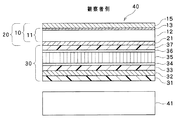
積層基材11、積層体10および偏光板20は、液晶表示パネルに組み込んで使用することができる。図6は、図1に示された積層体10および積層基材11、並びに、図5に示された偏光板20を組み込んだ液晶表示パネル30の概略構成図である。
≪Liquid crystal display panel≫
The
図6に示される液晶表示パネルは、光源側(バックライトユニット側)から観察者側に向けて、トリアセチルセルロースフィルム(TACフィルム)等の保護フィルム31、偏光素子32、位相差フィルム33、接着剤層34、液晶セル35、接着剤層36、位相差フィルム37、偏光素子21、積層体10の順に積層された構造を有している。液晶セル35は、2枚のガラス基材間に、液晶層、配向膜、電極層、カラーフィルタ等を配置したものである。
The liquid crystal display panel shown in FIG. 6 has a
位相差フィルム33、37としては、トリアセチルセルロースフィルムやシクロオレフィンポリマーフィルムが挙げられる。位相差フィルム37は、保護フィルム22と同一であってもよい。接着剤層34、36を構成する接着剤としては、感圧接着剤(PSA)が挙げられる。
Examples of the
≪画像表示装置≫
積層基材11、積層体10、偏光板20、液晶表示パネル30は、画像表示装置に組み込んで使用することができる。画像表示装置としては、例えば液晶ディスプレイ(LCD)、陰極線管表示装置(CRT)、プラズマディスプレイ(PDP)、エレクトロルミネッセンスディスプレイ(ELD)、フィールドエミッションディスプレイ(FED)、タッチパネル、タブレットPC、電子ペーパー等が挙げられる。図7は、図1に示された積層体10および積層基材11、図5に示された偏光板20、並びに、図6に示された液晶表示パネル30を組み込んだ画像表示装置40の一例である液晶ディスプレイの概略構成図である。
≪Image display device≫
The
図7に示される画像表示装置40は、液晶ディスプレイである。画像表示装置30は、バックライトユニット41と、バックライトユニット41よりも観察者側に配置された、積層体10を備える液晶表示パネル30とから構成されている。バックライトユニット41としては、公知のバックライトユニットが使用できる。
The
≪その他の用途≫
また、上述した積層基材11および積層体10は、画像表示装置30の表示面上に直接配置される用途以外の用途として、タッチパネルセンサを介して画像表示装置30上に設けられるようにしてもよい。この例においては、予めタッチパネルセンサ上に直接或いはたの部材を介して積層基材11又は積層体10を配置してなるタッチパネル装置を用意しておき、このタッチパネル装置を画像表示装置上に設けるようにしてもよい。
≪Other uses≫
Further, the above-mentioned
さらに、上述した積層基材11および積層体10は、干渉縞の発生が回避されるべき種々の用途で使用され得る。例えば、積層基材11および積層体10が、時計や、メーター類等の機器の表示部の窓材としても使用され得る。
Further, the above-mentioned
本発明を詳細に説明するために、以下に実施例を挙げて説明するが、本発明はこれらの記載に限定されない。 In order to explain the present invention in detail, examples will be given below, but the present invention is not limited to these descriptions.
以下に説明するようにして、実施例1および2、並びに、比較例1に係る積層体を作製した。作製された各積層体について、干渉縞の発生およびニジムラの発生を調査した。 As described below, the laminates according to Examples 1 and 2 and Comparative Example 1 were produced. The occurrence of interference fringes and the occurrence of Nijimura were investigated for each of the produced laminates.
(実施例1)
ポリエチレンテレフタレート材料を290℃で溶融して、フィルム形成ダイを通して、シート状に押出し、水冷冷却した回転急冷ドラム上に密着させて冷却し、未延伸フィルムを作製した。この未延伸フィルムを二軸延伸試験装置(東洋精機製)にて、120℃にて1分間予熱した後、120℃にて、延伸倍率4.5倍に延伸した後、その延伸方向とは90度の方向に延伸倍率1.5倍にて延伸を行い、n1x=1.70、n1y=1.60、膜厚80μm、リタデーション=8000nmの光透過性基材を得た。
(Example 1)
The polyethylene terephthalate material was melted at 290 ° C., extruded into a sheet through a film forming die, and cooled by being brought into close contact with a water-cooled rotary quenching drum to prepare an unstretched film. This unstretched film is preheated at 120 ° C. for 1 minute in a biaxial stretching test device (manufactured by Toyo Seiki Co., Ltd.), then stretched at 120 ° C. at a stretching ratio of 4.5 times, and then the stretching direction is 90. Stretching was carried out in the direction of degree at a stretching ratio of 1.5 times to obtain a light-transmitting substrate having n 1x = 1.70, n 1y = 1.60, a film thickness of 80 μm, and a retardation of 8000 nm.
光透過性基材上に光重合性液晶化合物を、シクロヘキサノンとn−プロピルアルコールの混合溶媒(溶媒比9:1)に20質量%溶解させ、光重合開始剤Irg184(チバ・スペシャルティ・ケミカルズ(株))を固形分に対して5%添加したインキを、バーコーターにより、乾燥後の膜厚が0.5μmとなるように、塗工した。次いで、70℃で4分間加熱して溶剤を乾燥除去すると共に、該光重合性液晶化合物を配向させ、さらに、塗工面に紫外線を照射することにより、上記光重合性液晶化合物を固定化して、n2x=1.60、n2y=1.55の屈折率調整層を積層した。 A photopolymerizable liquid crystal compound was dissolved in a mixed solvent of cyclohexanone and n-propyl alcohol (solvent ratio 9: 1) in an amount of 20% by mass on a light-transmitting substrate, and a photopolymerization initiator Irg184 (Ciba Specialty Chemicals Co., Ltd.) was dissolved. The ink obtained by adding 5% of)) to the solid content was coated with a bar coater so that the film thickness after drying was 0.5 μm. Next, the solvent was dried and removed by heating at 70 ° C. for 4 minutes, the photopolymerizable liquid crystal compound was oriented, and the coated surface was further irradiated with ultraviolet rays to immobilize the photopolymerizable liquid crystal compound. The refractive index adjusting layers of n 2x = 1.60 and n 2y = 1.55 were laminated.
次に、機能層として、光学的に等方性である、ペンタエリスリトールトリアクリレート(PETA)を、MIBK溶媒に30質量%溶解させ、光重合開始剤Irg184(チバ・スペシャルティ・ケミカルズ(株))を固形分に対して5%添加したインキを、バーコーターにより、乾燥後の膜厚が5μmとなるように塗工した。次いで、70℃で2分間加熱して、溶剤を除去し、塗工面に紫外線を照射することにより、固定化し、n3x=n3y=1.50の機能層を積層し、実施例1に係る積層体を得た。 Next, as a functional layer, pentaerythritol triacrylate (PETA), which is optically isotropic, was dissolved in a MIBK solvent in an amount of 30% by mass, and a photopolymerization initiator Irg184 (Ciba Specialty Chemicals Co., Ltd.) was added. The ink to which 5% was added to the solid content was coated with a bar coater so that the film thickness after drying was 5 μm. Next, it was heated at 70 ° C. for 2 minutes to remove the solvent, and the coated surface was fixed by irradiating the coated surface with ultraviolet rays, and a functional layer of n 3x = n 3y = 1.50 was laminated, and according to Example 1. A laminate was obtained.
(実施例2)
ポリエチレンテレフタレート材料を290℃で溶融して、フィルム形成ダイを通して、シート状に押出し、水冷冷却した回転急冷ドラム上に密着させて冷却し、未延伸フィルムを作製した。この未延伸フィルムを二軸延伸試験装置(東洋精機製)にて、120℃にて1分間予熱した後、120℃にて、延伸倍率4.5倍に延伸した後、その延伸方向とは90度の方向に延伸倍率1.5倍にて延伸を行い、n1x=1.70、n1y=1.60、膜厚33μm、リタデーション=3300nmの光透過性基材を得た。得られた光透過性基材上に、実施例1と同様にして屈折率調整層及び機能層を形成して、実施例2に係る積層体を得た。すなわち、実施例2に係る積層体は、実施例1に係る積層体と、光透過性基材の厚みが異なっている。
(Example 2)
The polyethylene terephthalate material was melted at 290 ° C., extruded into a sheet through a film forming die, and cooled by being brought into close contact with a water-cooled rotary quenching drum to prepare an unstretched film. This unstretched film is preheated at 120 ° C. for 1 minute in a biaxial stretching test device (manufactured by Toyo Seiki Co., Ltd.), then stretched at 120 ° C. at a stretching ratio of 4.5 times, and then the stretching direction is 90. Stretching was carried out in the direction of degree at a stretching ratio of 1.5 times to obtain a light-transmitting substrate having n 1x = 1.70, n 1y = 1.60, a film thickness of 33 μm, and a retardation of 3300 nm. A refractive index adjusting layer and a functional layer were formed on the obtained light-transmitting substrate in the same manner as in Example 1 to obtain a laminate according to Example 2. That is, the laminate according to Example 2 has a different thickness of the light-transmitting base material from the laminate according to Example 1.
(比較例1)
実施例1の屈折率調整層の変わりに、ペンタエリスリトールトリアクリレート:五酸化アンチモン=7:3からなる中間層を用いた以外は、実施例1に係る積層体と同様の方法にて、比較例1に係る積層体を作製した。比較例1に係る積層体の中間層は光学的に等方性であり、n2x=n2y=1.575であった。
(Comparative Example 1)
Comparative Example in the same manner as the laminate according to Example 1 except that an intermediate layer composed of pentaerythritol triacrylate: antimony pentoxide = 7: 3 was used instead of the refractive index adjusting layer of Example 1. The laminate according to No. 1 was produced. The intermediate layer of the laminate according to Comparative Example 1 was optically isotropic, and n 2x = n 2y = 1.575.
(参考例1)
ポリエチレンテレフタレート材料を290℃で溶融して、フィルム形成ダイを通して、シート状に押出し、水冷冷却した回転急冷ドラム上に密着させて冷却し、未延伸フィルムを作製した。この未延伸フィルムを二軸延伸試験装置(東洋精機製)にて、120℃にて1分間予熱した後、120℃にて、延伸倍率4.5倍に延伸した後、その延伸方向とは90度の方向に延伸倍率1.5倍にて延伸を行い、n1x=1.70、n1y=1.60、膜厚28μm、リタデーション=2800nmの光透過性基材を得た。得られた光透過性基材上に、実施例1と同様にして屈折率調整層及び機能層を形成して、参考例1に係る積層体を得た。すなわち、実施例2に係る積層体は、実施例1に係る積層体と、光透過性基材の厚みが異なっている。
(Reference example 1)
The polyethylene terephthalate material was melted at 290 ° C., extruded into a sheet through a film forming die, and cooled by being brought into close contact with a water-cooled rotary quenching drum to prepare an unstretched film. This unstretched film is preheated at 120 ° C. for 1 minute in a biaxial stretching test device (manufactured by Toyo Seiki Co., Ltd.), then stretched at 120 ° C. at a stretching ratio of 4.5 times, and then the stretching direction is 90. Stretching was carried out in the direction of degree at a stretching ratio of 1.5 times to obtain a light-transmitting substrate having n 1x = 1.70, n 1y = 1.60, a film thickness of 28 μm, and a retardation of 2800 nm. A refractive index adjusting layer and a functional layer were formed on the obtained light-transmitting substrate in the same manner as in Example 1 to obtain a laminate according to Reference Example 1. That is, the laminate according to Example 2 has a different thickness of the light-transmitting base material from the laminate according to Example 1.
(光透過基材の屈折率とリタデーションの測定)
光透過基材の屈折率とリタデーションは、次のようにして測定した。まず、延伸後の光透過基材を、二枚の偏光板を用いて、フィルムの配向軸方向を求め、配向軸方向に対して直交する二つの軸の波長590nmに対する屈折率(nx,ny)を、アッベ屈折率計(アタゴ社製 NAR−4T)によって求めた。ここで、より大きい屈折率を示す軸を遅相軸と定義する。フィルム厚みd(nm)は、電気マイクロメータ(アンリツ社製)を用いて測定し、単位をnmに換算した。屈折率差(n1x−n1y)と、フィルムの厚みd(nm)の積より、リタデーションを計算した。
(Measurement of refractive index and retardation of light transmitting substrate)
The refractive index and retardation of the light transmitting substrate were measured as follows. First, the orientation axis direction of the film is determined from the stretched light-transmitting substrate using two polarizing plates, and the refractive index (nx, ny) of the two axes orthogonal to the orientation axis direction with respect to the wavelength of 590 nm. Was determined by an Abbe refractive index meter (NAR-4T manufactured by Atago Co., Ltd.). Here, an axis showing a higher refractive index is defined as a slow-phase axis. The film thickness d (nm) was measured using an electric micrometer (manufactured by Anritsu), and the unit was converted to nm. The retardation was calculated from the product of the difference in refractive index (n 1x −n 1y ) and the thickness d (nm) of the film.
(屈折率調整層の屈折率の測定)
屈折率調整層の屈折率は、次のようにして測定した。実施例1および2に用いた光重合性液晶化合物の場合、光学的に等方性であるガラス基板上に、配向膜材料であるポリイミドを塗布し、ラビング処理を施す。この基材上に光重合性液晶化合物を、シクロヘキサノンとn−プロピルアルコールの混合溶媒(溶媒比9:1)に20質量%溶解させたインキを、スピンコーターにより、乾燥後の膜厚が1umとなるように、塗布した。次いで、70℃で4分間加熱して溶剤を乾燥除去すると共に、該光重合性液晶化合物を配向させ、さらに、塗工面に紫外線を照射することにより、上記光重合性液晶化合物を固定化して得た屈折率調整層を、光透過基材と同様の方法にて、屈折率を測定した。
(Measurement of refractive index of refractive index adjustment layer)
The refractive index of the refractive index adjusting layer was measured as follows. In the case of the photopolymerizable liquid crystal compounds used in Examples 1 and 2, polyimide, which is an alignment film material, is coated on an optically isotropic glass substrate and subjected to a rubbing treatment. An ink obtained by dissolving 20% by mass of a photopolymerizable liquid crystal compound on this substrate in a mixed solvent of cyclohexanone and n-propyl alcohol (solvent ratio 9: 1) was prepared by a spin coater to have a film thickness of 1 um after drying. It was applied so as to be. Next, the photopolymerizable liquid crystal compound was fixed and obtained by heating at 70 ° C. for 4 minutes to dry and remove the solvent, orienting the photopolymerizable liquid crystal compound, and further irradiating the coated surface with ultraviolet rays. The refractive index of the refractive index adjusting layer was measured in the same manner as that of the light transmitting substrate.
(複屈折を有するか否かの判断)
複屈折を有するか否かは、次のようにして判断した。王子計測機器製KOBRA−WRを用いて、測定角0°且つ測定波長589.3nmに設定して、面内位相差を測定し、面内位相差が20nm未満のものは、複屈折を有さないと判断し、20nm以上のものは、複屈折を有すると判断した。
(Judgment as to whether or not it has birefringence)
Whether or not it had birefringence was determined as follows. Using KOBRA-WR manufactured by Oji Measuring Instruments, the measurement angle is set to 0 ° and the measurement wavelength is set to 589.3 nm, and the in-plane phase difference is measured. Those with an in-plane phase difference of less than 20 nm have birefringence. It was judged that there was no such thing, and those having a wavelength of 20 nm or more were judged to have birefringence.
(等方性である材料の屈折率測定)
等方性である材料(中間層および機能層)の屈折率は、アッベ屈折率計(アタゴ社製 NAR−4T)によって測定した。
(Measurement of refractive index of isotropic material)
The refractive index of the isotropic material (intermediate layer and functional layer) was measured by an Abbe refractive index meter (NAR-4T manufactured by Atago).
(干渉縞評価)
各積層体における干渉縞の発生を次のようにして評価した。フナテック社製の干渉縞検査ランプ(Naランプ)を用い、目視にて得られた防眩性フィルムの干渉縞の有無を検査し、下記基準で評価した。得られた防眩性フィルムは、塗工面の反対側を黒インキで塗りつぶし、塗工面に干渉縞検査ランプをあて、反射観察にて評価を行った。
○:干渉縞が観察されるが、極めて薄く、実使用上問題ないレベル。
×:干渉縞がはっきり観察される。
(Evaluation of interference fringes)
The occurrence of interference fringes in each laminate was evaluated as follows. Using an interference fringe inspection lamp (Na lamp) manufactured by Funatec, the presence or absence of interference fringes in the visually obtained antiglare film was inspected and evaluated according to the following criteria. The obtained antiglare film was evaluated by coating the opposite side of the coated surface with black ink, applying an interference fringe inspection lamp to the coated surface, and observing reflection.
◯: Interference fringes are observed, but they are extremely thin and have no problem in actual use.
X: Interference fringes are clearly observed.
(ニジムラ評価)
各サンプルにおけるニジムラの発生を次のようにして評価した。各積層基材を、LEDバックライト液晶モニター(FLATORON IPS226V(LG Electronics Japan社製))の観察者側の偏光素子上に配置し、液晶表示装置を作製した。なお、ポリエステル基材の遅相軸と液晶モニターの観察者側の偏光素子の吸収軸とのなす角度が45°となるように配置した。そして、暗所及び明所(液晶モニター周辺照度400ルクス)にて、正面及び斜め方向(約50度)から目視及び偏光サングラス越しに表示画像の観察を行い、ニジムラの有無を以下の基準に従い評価した。偏光サングラス越しの観察は、目視よりも非常に厳しい評価法である。観察は10人で行い、最多数の評価を観察結果としている。
◎:ニジムラが観測されない
○:ニジムラが観測されるが、実使用上問題ないレベル
×:ニジムラが強く観測される
(Nijimura evaluation)
The occurrence of Nijimura in each sample was evaluated as follows. Each laminated substrate was placed on a polarizing element on the observer side of an LED-backlit liquid crystal monitor (FLATORON IPS226V (manufactured by LG Electronics Japan)) to produce a liquid crystal display device. It was arranged so that the angle formed by the slow axis of the polyester base material and the absorption axis of the polarizing element on the observer side of the liquid crystal monitor was 45 °. Then, in a dark place and a bright place (illuminance around the LCD monitor 400 lux), the displayed image is visually observed and observed through polarized sunglasses from the front and diagonal direction (about 50 degrees), and the presence or absence of Nijimura is evaluated according to the following criteria. did. Observation through polarized sunglasses is a much stricter evaluation method than visual observation. The observation was carried out by 10 people, and the largest number of evaluations were the observation results.
◎: Nijimura is not observed ○: Nijimura is observed, but there is no problem in actual use ×: Nijimura is strongly observed
干渉縞およびニジムラの評価結果を表1に示す。

Claims (16)
前記積層基材の一方の面上に設けられた機能層と、を備え、
前記積層基材は、
面内の複屈折性を有する光透過性基材と、
前記光透過性基材と積層され面内の複屈折性を有する光透過性基材であって、前記光透過性基材と前記機能層との間に位置して前記光透過性基材と前記機能層との間に存在する界面の屈折率差を前記光透過性基材と前記機能層との屈折率差よりも低減するようになる屈折率調整層と、を備え、
前記光透過性基材の面内における最も屈折率が大きい方向である遅相軸方向における屈折率n1x、前記光透過性基材の前記遅相軸方向と平行な方向における前記屈折率調整層の屈折率n2x、および、前記光透過性基材の前記遅相軸方向と平行となる方向における前記機能層の屈折率n3xが、
n1x>n2x>n3x
なる関係を満たし、
前記光透過性基材の前記遅相軸方向に直交する進相軸方向における屈折率n1y、前記光透過性基材の前記進相軸方向と平行な方向における前記屈折率調整層の屈折率n2y、および、前記光透過性基材の前記進相軸方向と平行となる方向における前記機能層の屈折率n3yが、
n1y<n2y<n3y
なる関係を満たす、積層体。 Laminated substrate and
A functional layer provided on one surface of the laminated base material is provided.
The laminated base material is
With an in-plane birefringent light-transmitting substrate,
A light-transmitting base material which is laminated with the light-transmitting base material and has in-plane double refractive index, and is located between the light-transmitting base material and the functional layer to form the light-transmitting base material. It is provided with a refractive index adjusting layer that reduces the difference in refractive index of the interface existing between the functional layer and the light-transmitting substrate to be smaller than the difference in refractive index between the light-transmitting base material and the functional layer .
The refractive index n 1x in the slow axis direction, which is the direction in which the refractive index is the largest in the plane of the light transmissive substrate, and the refractive index adjusting layer in the direction parallel to the slow axis direction of the light transmissive substrate. The refractive index n 2x of the functional layer and the refractive index n 3x of the functional layer in the direction parallel to the slow axis direction of the light transmissive substrate.
n 1x > n 2x > n 3x
Satisfy the relationship
The refractive index n 1y in the phase-advancing axis direction orthogonal to the slow-phase axis direction of the light-transmitting base material, and the refractive index of the refractive index adjusting layer in the direction parallel to the phase-advancing axis direction of the light-transmitting base material. n 2y and the refractive index n 3y of the functional layer in the direction parallel to the phase advance axis direction of the light transmissive substrate are
n 1y <n 2y <n 3y
A laminated body that satisfies the relationship.
(n1x−n1y)>(n2a−n2b)なる関係を満たす、請求項3または4に記載の積層体。 The refractive index n 1x of the light-transmitting base material in the slow-phase axial direction, the refractive index n 1y of the light-transmitting base material in the phase-advancing axis direction, and the highest refractive index in the plane of the refractive index adjusting layer. The refractive index n 2a in the slow axis direction of the refractive index adjusting layer, which is the direction, and the refractive index n 2b in the phase advance axis direction of the refractive index adjusting layer orthogonal to the slow axis direction of the refractive index adjusting layer. But,
The laminate according to claim 3 or 4, which satisfies the relationship (n 1x −n 1y )> (n 2a −n 2b ).
n2=(n2x+n2y)/2、且つ
|n2x−((n1x+n3x)/2)|<|n2−((n1x+n3x)/2)|なる関係を満たし、
前記光透過性基材の前記進相軸方向における屈折率n1y、前記光透過性基材の前記進相軸方向と平行な方向における前記屈折率調整層の屈折率n2y、及び、前記光透過性基材の前記進相軸方向と平行な方向における前記機能層の屈折率n3yが、
n2=(n2x+n2y)/2、且つ
|n2y−((n1y+n3y)/2)|<|n2−((n1y+n3y)/2)|なる関係を満たす、請求項1〜5のいずれか一項に記載の積層体。 The refractive index n 1x of the light transmitting substrate in the slow axis direction, the refractive index n 2x of the refractive index adjusting layer in the direction parallel to the slow axis direction dx of the light transmitting substrate, and The refractive index n 3x of the functional layer in the direction parallel to the slow axis direction of the light transmissive substrate is
n 2 = (n 2x + n 2y ) / 2 and | n 2x − ((n 1x + n 3x ) / 2) | <| n 2 − ((n 1x + n 3x ) / 2) |
The refractive index n 1y of the light-transmitting substrate in the phase-advancing axis direction, the refractive index n 2y of the refractive index adjusting layer in the direction parallel to the phase-advancing axis direction of the light-transmitting substrate, and the light. The refractive index n3y of the functional layer in the direction parallel to the phase-advancing axis direction of the permeable base material is
Claim that satisfies the relationship of n 2 = (n 2x + n 2y ) / 2 and | n 2y − ((n 1y + n 3y ) / 2) | <| n 2 − ((n 1y + n 3y ) / 2) | Item 2. The laminate according to any one of Items 1 to 5.
請求項1〜11のいずれか一項に記載の積層体と、を備える、偏光板。 Polarizing element and
A polarizing plate comprising the laminate according to any one of claims 1 to 11.
前記積層基材は、
面内の複屈折性を有する光透過性基材と、
前記光透過性基材と積層され面内の複屈折性を有する屈折率調整層であって、前記光透過性基材と前記機能層との間に位置して前記光透過性基材と前記機能層との間に存在する界面の屈折率差を前記光透過性基材と前記機能層との屈折率差よりも低減するようになる屈折率調整層と、を備え、
前記光透過性基材の面内における最も屈折率が大きい方向である遅相軸方向における屈折率n1x、前記光透過性基材の前記遅相軸方向と平行な方向における前記屈折率調整層の屈折率n2x、および、前記光透過性基材の前記遅相軸方向と平行となる方向における前記機能層の屈折率n3xが、
n1x>n2x>n3x
なる関係を満たし、
前記光透過性基材の前記遅相軸方向に直交する進相軸方向における屈折率n1y、前記光透過性基材の前記進相軸方向と平行な方向における前記屈折率調整層の屈折率n2y、および、前記光透過性基材の前記進相軸方向と平行となる方向における前記機能層の屈折率n3yが、
n1y<n2y<n3y
なる関係を満たす、機能層の使用方法。 A method of using a functional layer by laminating on one surface of a laminated base material.
The laminated base material is
With an in-plane birefringent light-transmitting substrate,
A refractive index adjustment layer having birefringence of the light transmitting substrate with the laminated plane, the said light transmitting substrate is positioned between the functional layer and the light transmitting substrate It is provided with a refractive index adjusting layer that reduces the difference in refractive index of the interface existing between the functional layer and the light-transmitting substrate to be smaller than the difference in refractive index between the light-transmitting base material and the functional layer .
The refractive index n 1x in the slow axis direction, which is the direction in which the refractive index is the largest in the plane of the light transmissive substrate, and the refractive index adjusting layer in the direction parallel to the slow axis direction of the light transmissive substrate. The refractive index n 2x of the functional layer and the refractive index n 3x of the functional layer in the direction parallel to the slow axis direction of the light transmissive substrate.
n 1x > n 2x > n 3x
Satisfy the relationship
The refractive index n 1y in the phase-advancing axis direction orthogonal to the slow-phase axis direction of the light-transmitting base material, and the refractive index of the refractive index adjusting layer in the direction parallel to the phase-advancing axis direction of the light-transmitting base material. n 2y and the refractive index n 3y of the functional layer in the direction parallel to the phase advance axis direction of the light transmissive substrate are
n 1y <n 2y <n 3y
How to use the functional layer that satisfies the relationship.
前記積層基材は、
面内の複屈折性を有する光透過性基材と、
前記光透過性基材と積層され面内の複屈折性を有する屈折率調整層であって、前記光透過性基材と前記機能層との間に位置して前記光透過性基材と前記機能層との間に存在する界面の屈折率差を前記光透過性基材と前記機能層との屈折率差よりも低減するようになる屈折率調整層と、を備え、
前記光透過性基材の面内における最も屈折率が大きい方向である遅相軸方向における屈折率n1x、前記光透過性基材の前記遅相軸方向と平行な方向における前記屈折率調整層の屈折率n2x、および、前記光透過性基材の前記遅相軸方向と平行となる方向における前記機能層の屈折率n3xが、
n1x>n2x>n3x
なる関係を満たし、
前記光透過性基材の前記遅相軸方向に直交する進相軸方向における屈折率n1y、前記光透過性基材の前記進相軸方向と平行な方向における前記屈折率調整層の屈折率n2y、および、前記光透過性基材の前記進相軸方向と平行となる方向における前記機能層の屈折率n3yが、
n1y<n2y<n3y
なる関係を満たす、積層体の製造方法。 A step of laminating a functional layer on one surface of a laminated base material is provided.
The laminated base material is
With an in-plane birefringent light-transmitting substrate,
A refractive index adjustment layer having birefringence of the light transmitting substrate with the laminated plane, the said light transmitting substrate is positioned between the functional layer and the light transmitting substrate It is provided with a refractive index adjusting layer that reduces the difference in refractive index of the interface existing between the functional layer and the light-transmitting substrate to be smaller than the difference in refractive index between the light-transmitting base material and the functional layer .
The refractive index n 1x in the slow axis direction, which is the direction in which the refractive index is the largest in the plane of the light transmissive substrate, and the refractive index adjusting layer in the direction parallel to the slow axis direction of the light transmissive substrate. The refractive index n 2x of the functional layer and the refractive index n 3x of the functional layer in the direction parallel to the slow axis direction of the light transmissive substrate.
n 1x > n 2x > n 3x
Satisfy the relationship
The refractive index n 1y in the phase-advancing axis direction orthogonal to the slow-phase axis direction of the light-transmitting base material, and the refractive index of the refractive index adjusting layer in the direction parallel to the phase-advancing axis direction of the light-transmitting base material. n 2y and the refractive index n 3y of the functional layer in the direction parallel to the phase advance axis direction of the light transmissive substrate are
n 1y <n 2y <n 3y
A method for manufacturing a laminate that satisfies the above relationship.
Applications Claiming Priority (2)
| Application Number | Priority Date | Filing Date | Title |
|---|---|---|---|
| JP2012111500 | 2012-05-15 | ||
| JP2012111500 | 2012-05-15 |
Related Parent Applications (1)
| Application Number | Title | Priority Date | Filing Date |
|---|---|---|---|
| JP2013102229A Division JP2013257550A (en) | 2012-05-15 | 2013-05-14 | Laminate substrate, laminate, polarizing plate, liquid crystal display panel, and image display device |
Publications (2)
| Publication Number | Publication Date |
|---|---|
| JP2018028667A JP2018028667A (en) | 2018-02-22 |
| JP6815955B2 true JP6815955B2 (en) | 2021-01-20 |
Family
ID=49855279
Family Applications (2)
| Application Number | Title | Priority Date | Filing Date |
|---|---|---|---|
| JP2013102229A Pending JP2013257550A (en) | 2012-05-15 | 2013-05-14 | Laminate substrate, laminate, polarizing plate, liquid crystal display panel, and image display device |
| JP2017171495A Active JP6815955B2 (en) | 2012-05-15 | 2017-09-06 | Laminates, polarizing plates, liquid crystal display panels and image display devices |
Family Applications Before (1)
| Application Number | Title | Priority Date | Filing Date |
|---|---|---|---|
| JP2013102229A Pending JP2013257550A (en) | 2012-05-15 | 2013-05-14 | Laminate substrate, laminate, polarizing plate, liquid crystal display panel, and image display device |
Country Status (3)
| Country | Link |
|---|---|
| JP (2) | JP2013257550A (en) |
| KR (1) | KR101947838B1 (en) |
| TW (1) | TWI580994B (en) |
Families Citing this family (3)
| Publication number | Priority date | Publication date | Assignee | Title |
|---|---|---|---|---|
| KR102455947B1 (en) | 2016-02-15 | 2022-10-17 | 후지필름 가부시키가이샤 | Polyester film and manufacturing method therefor, hard coat film and manufacturing method therefor, image display apparatus, and touch panel |
| JP6734694B2 (en) * | 2016-04-28 | 2020-08-05 | 日東電工株式会社 | Hard coat film, method for producing the same, and transparent conductive film |
| CN112199979A (en) * | 2019-07-07 | 2021-01-08 | 奕力科技股份有限公司 | Display device capable of detecting fingerprint of finger and fingerprint identification chip |
Family Cites Families (20)
| Publication number | Priority date | Publication date | Assignee | Title |
|---|---|---|---|---|
| US6157490A (en) * | 1998-01-13 | 2000-12-05 | 3M Innovative Properties Company | Optical film with sharpened bandedge |
| US6179948B1 (en) * | 1998-01-13 | 2001-01-30 | 3M Innovative Properties Company | Optical film and process for manufacture thereof |
| US6207260B1 (en) * | 1998-01-13 | 2001-03-27 | 3M Innovative Properties Company | Multicomponent optical body |
| JP4314803B2 (en) * | 2001-09-28 | 2009-08-19 | 日油株式会社 | Anti-reflection film |
| JP5714435B2 (en) * | 2001-11-09 | 2015-05-07 | 大日本印刷株式会社 | Optical element manufacturing method |
| JP2005037927A (en) * | 2003-06-26 | 2005-02-10 | Nippon Zeon Co Ltd | Optical multilayer film |
| JP4475016B2 (en) * | 2003-06-30 | 2010-06-09 | 東レ株式会社 | Hard coat film, antireflection film and image display device |
| JP2006163151A (en) * | 2004-12-09 | 2006-06-22 | Bridgestone Corp | Antireflection film and filter for display having this antireflection film |
| JP2007178999A (en) * | 2005-11-29 | 2007-07-12 | Bridgestone Corp | Antireflection film and filter for display |
| JP4816183B2 (en) * | 2006-03-24 | 2011-11-16 | 東レ株式会社 | Optically laminated biaxially stretched polyester film and hard coat film using the same |
| US7599592B2 (en) * | 2006-08-30 | 2009-10-06 | 3M Innovative Properties Company | Polymer fiber polarizers with aligned fibers |
| JP2008089894A (en) * | 2006-09-29 | 2008-04-17 | Dainippon Printing Co Ltd | Method for manufacturing retardation filmmethod for manufacturing retardation film |
| JP2009093148A (en) * | 2007-02-13 | 2009-04-30 | Sony Corp | Optical package, method for manufacturing the same, illuminator and display |
| JP5593627B2 (en) * | 2009-03-31 | 2014-09-24 | 東レ株式会社 | Laminated polyester film and method for producing the same |
| JP5520138B2 (en) * | 2009-06-12 | 2014-06-11 | 三菱樹脂株式会社 | Laminated polyester film |
| JP4888853B2 (en) * | 2009-11-12 | 2012-02-29 | 学校法人慶應義塾 | Method for improving visibility of liquid crystal display device, and liquid crystal display device using the same |
| JP2011245809A (en) * | 2010-05-29 | 2011-12-08 | Mitsubishi Plastics Inc | Laminated polyester film |
| JP5460481B2 (en) * | 2010-06-22 | 2014-04-02 | 三菱樹脂株式会社 | Laminated polyester film |
| CN102959459B (en) * | 2010-06-22 | 2019-06-18 | 东洋纺株式会社 | Liquid crystal display device, polarization plates and polaroid protective film |
| JP5614506B2 (en) * | 2011-11-29 | 2014-10-29 | 東洋紡株式会社 | Liquid crystal display device, polarizing plate and polarizer protective film |
-
2013
- 2013-04-30 TW TW102115454A patent/TWI580994B/en active
- 2013-05-14 JP JP2013102229A patent/JP2013257550A/en active Pending
- 2013-05-14 KR KR1020130054152A patent/KR101947838B1/en active IP Right Grant
-
2017
- 2017-09-06 JP JP2017171495A patent/JP6815955B2/en active Active
Also Published As
| Publication number | Publication date |
|---|---|
| TWI580994B (en) | 2017-05-01 |
| KR101947838B1 (en) | 2019-02-13 |
| TW201350898A (en) | 2013-12-16 |
| JP2013257550A (en) | 2013-12-26 |
| KR20130127938A (en) | 2013-11-25 |
| JP2018028667A (en) | 2018-02-22 |
Similar Documents
| Publication | Publication Date | Title |
|---|---|---|
| US10761366B2 (en) | Optical layered body, polarizer, method for producing polarizer, image display device, method for producing image display device, and method for improving visibility of image display device | |
| US9989688B2 (en) | Polarizing plate, image display apparatus, and method for improving bright-place contrast in image display apparatus | |
| TW201512712A (en) | Polarizer, image display device, and contrast improvement method for image display device at bright spot | |
| JP6815955B2 (en) | Laminates, polarizing plates, liquid crystal display panels and image display devices | |
| JP2013246371A (en) | Optical laminate, polarizing plate and image display apparatus | |
| JP6048010B2 (en) | Laminated body, polarizing plate, liquid crystal panel, touch panel sensor, touch panel device and image display device | |
| KR101982377B1 (en) | Laminate, polarizer, liquid crystal panel, touch panel sensor, touch panel device, and image display device | |
| JP6048009B2 (en) | Laminated body, polarizing plate, liquid crystal panel, touch panel sensor, touch panel device and image display device |
Legal Events
| Date | Code | Title | Description |
|---|---|---|---|
| A621 | Written request for application examination |
Free format text: JAPANESE INTERMEDIATE CODE: A621 Effective date: 20171005 |
|
| A521 | Written amendment |
Free format text: JAPANESE INTERMEDIATE CODE: A523 Effective date: 20171013 |
|
| A131 | Notification of reasons for refusal |
Free format text: JAPANESE INTERMEDIATE CODE: A131 Effective date: 20180629 |
|
| A977 | Report on retrieval |
Free format text: JAPANESE INTERMEDIATE CODE: A971007 Effective date: 20180627 |
|
| A601 | Written request for extension of time |
Free format text: JAPANESE INTERMEDIATE CODE: A601 Effective date: 20180828 |
|
| A521 | Written amendment |
Free format text: JAPANESE INTERMEDIATE CODE: A523 Effective date: 20181029 |
|
| A131 | Notification of reasons for refusal |
Free format text: JAPANESE INTERMEDIATE CODE: A131 Effective date: 20190312 |
|
| A521 | Written amendment |
Free format text: JAPANESE INTERMEDIATE CODE: A523 Effective date: 20190513 |
|
| A02 | Decision of refusal |
Free format text: JAPANESE INTERMEDIATE CODE: A02 Effective date: 20191101 |
|
| A521 | Written amendment |
Free format text: JAPANESE INTERMEDIATE CODE: A523 Effective date: 20200131 |
|
| C60 | Trial request (containing other claim documents, opposition documents) |
Free format text: JAPANESE INTERMEDIATE CODE: C60 Effective date: 20200131 |
|
| A911 | Transfer to examiner for re-examination before appeal (zenchi) |
Free format text: JAPANESE INTERMEDIATE CODE: A911 Effective date: 20200207 |
|
| C21 | Notice of transfer of a case for reconsideration by examiners before appeal proceedings |
Free format text: JAPANESE INTERMEDIATE CODE: C21 Effective date: 20200214 |
|
| A912 | Re-examination (zenchi) completed and case transferred to appeal board |
Free format text: JAPANESE INTERMEDIATE CODE: A912 Effective date: 20200501 |
|
| C211 | Notice of termination of reconsideration by examiners before appeal proceedings |
Free format text: JAPANESE INTERMEDIATE CODE: C211 Effective date: 20200508 |
|
| C22 | Notice of designation (change) of administrative judge |
Free format text: JAPANESE INTERMEDIATE CODE: C22 Effective date: 20200707 |
|
| C302 | Record of communication |
Free format text: JAPANESE INTERMEDIATE CODE: C302 Effective date: 20200909 |
|
| C13 | Notice of reasons for refusal |
Free format text: JAPANESE INTERMEDIATE CODE: C13 Effective date: 20200911 |
|
| C22 | Notice of designation (change) of administrative judge |
Free format text: JAPANESE INTERMEDIATE CODE: C22 Effective date: 20200911 |
|
| A521 | Written amendment |
Free format text: JAPANESE INTERMEDIATE CODE: A523 Effective date: 20200918 |
|
| C23 | Notice of termination of proceedings |
Free format text: JAPANESE INTERMEDIATE CODE: C23 Effective date: 20201020 |
|
| C03 | Trial/appeal decision taken |
Free format text: JAPANESE INTERMEDIATE CODE: C03 Effective date: 20201204 |
|
| C30A | Notification sent |
Free format text: JAPANESE INTERMEDIATE CODE: C3012 Effective date: 20201204 |
|
| A61 | First payment of annual fees (during grant procedure) |
Free format text: JAPANESE INTERMEDIATE CODE: A61 Effective date: 20201223 |
|
| R150 | Certificate of patent or registration of utility model |
Ref document number: 6815955 Country of ref document: JP Free format text: JAPANESE INTERMEDIATE CODE: R150 |