JP6812552B2 - Solar thermal power generation equipment - Google Patents
Solar thermal power generation equipment Download PDFInfo
- Publication number
- JP6812552B2 JP6812552B2 JP2019529080A JP2019529080A JP6812552B2 JP 6812552 B2 JP6812552 B2 JP 6812552B2 JP 2019529080 A JP2019529080 A JP 2019529080A JP 2019529080 A JP2019529080 A JP 2019529080A JP 6812552 B2 JP6812552 B2 JP 6812552B2
- Authority
- JP
- Japan
- Prior art keywords
- steam
- turbine
- heat
- generator
- heat storage
- Prior art date
- Legal status (The legal status is an assumption and is not a legal conclusion. Google has not performed a legal analysis and makes no representation as to the accuracy of the status listed.)
- Active
Links
Images


Classifications
-
- F—MECHANICAL ENGINEERING; LIGHTING; HEATING; WEAPONS; BLASTING
- F03—MACHINES OR ENGINES FOR LIQUIDS; WIND, SPRING, OR WEIGHT MOTORS; PRODUCING MECHANICAL POWER OR A REACTIVE PROPULSIVE THRUST, NOT OTHERWISE PROVIDED FOR
- F03G—SPRING, WEIGHT, INERTIA OR LIKE MOTORS; MECHANICAL-POWER PRODUCING DEVICES OR MECHANISMS, NOT OTHERWISE PROVIDED FOR OR USING ENERGY SOURCES NOT OTHERWISE PROVIDED FOR
- F03G6/00—Devices for producing mechanical power from solar energy
- F03G6/06—Devices for producing mechanical power from solar energy with solar energy concentrating means
- F03G6/065—Devices for producing mechanical power from solar energy with solar energy concentrating means having a Rankine cycle
- F03G6/067—Binary cycle plants where the fluid from the solar collector heats the working fluid via a heat exchanger
-
- F—MECHANICAL ENGINEERING; LIGHTING; HEATING; WEAPONS; BLASTING
- F01—MACHINES OR ENGINES IN GENERAL; ENGINE PLANTS IN GENERAL; STEAM ENGINES
- F01K—STEAM ENGINE PLANTS; STEAM ACCUMULATORS; ENGINE PLANTS NOT OTHERWISE PROVIDED FOR; ENGINES USING SPECIAL WORKING FLUIDS OR CYCLES
- F01K11/00—Plants characterised by the engines being structurally combined with boilers or condensers
- F01K11/02—Plants characterised by the engines being structurally combined with boilers or condensers the engines being turbines
-
- F—MECHANICAL ENGINEERING; LIGHTING; HEATING; WEAPONS; BLASTING
- F01—MACHINES OR ENGINES IN GENERAL; ENGINE PLANTS IN GENERAL; STEAM ENGINES
- F01K—STEAM ENGINE PLANTS; STEAM ACCUMULATORS; ENGINE PLANTS NOT OTHERWISE PROVIDED FOR; ENGINES USING SPECIAL WORKING FLUIDS OR CYCLES
- F01K23/00—Plants characterised by more than one engine delivering power external to the plant, the engines being driven by different fluids
- F01K23/02—Plants characterised by more than one engine delivering power external to the plant, the engines being driven by different fluids the engine cycles being thermally coupled
- F01K23/06—Plants characterised by more than one engine delivering power external to the plant, the engines being driven by different fluids the engine cycles being thermally coupled combustion heat from one cycle heating the fluid in another cycle
- F01K23/08—Plants characterised by more than one engine delivering power external to the plant, the engines being driven by different fluids the engine cycles being thermally coupled combustion heat from one cycle heating the fluid in another cycle with working fluid of one cycle heating the fluid in another cycle
-
- F—MECHANICAL ENGINEERING; LIGHTING; HEATING; WEAPONS; BLASTING
- F01—MACHINES OR ENGINES IN GENERAL; ENGINE PLANTS IN GENERAL; STEAM ENGINES
- F01K—STEAM ENGINE PLANTS; STEAM ACCUMULATORS; ENGINE PLANTS NOT OTHERWISE PROVIDED FOR; ENGINES USING SPECIAL WORKING FLUIDS OR CYCLES
- F01K23/00—Plants characterised by more than one engine delivering power external to the plant, the engines being driven by different fluids
- F01K23/02—Plants characterised by more than one engine delivering power external to the plant, the engines being driven by different fluids the engine cycles being thermally coupled
- F01K23/06—Plants characterised by more than one engine delivering power external to the plant, the engines being driven by different fluids the engine cycles being thermally coupled combustion heat from one cycle heating the fluid in another cycle
- F01K23/10—Plants characterised by more than one engine delivering power external to the plant, the engines being driven by different fluids the engine cycles being thermally coupled combustion heat from one cycle heating the fluid in another cycle with exhaust fluid of one cycle heating the fluid in another cycle
- F01K23/106—Plants characterised by more than one engine delivering power external to the plant, the engines being driven by different fluids the engine cycles being thermally coupled combustion heat from one cycle heating the fluid in another cycle with exhaust fluid of one cycle heating the fluid in another cycle with water evaporated or preheated at different pressures in exhaust boiler
- F01K23/108—Regulating means specially adapted therefor
-
- F—MECHANICAL ENGINEERING; LIGHTING; HEATING; WEAPONS; BLASTING
- F01—MACHINES OR ENGINES IN GENERAL; ENGINE PLANTS IN GENERAL; STEAM ENGINES
- F01K—STEAM ENGINE PLANTS; STEAM ACCUMULATORS; ENGINE PLANTS NOT OTHERWISE PROVIDED FOR; ENGINES USING SPECIAL WORKING FLUIDS OR CYCLES
- F01K23/00—Plants characterised by more than one engine delivering power external to the plant, the engines being driven by different fluids
- F01K23/12—Plants characterised by more than one engine delivering power external to the plant, the engines being driven by different fluids the engines being mechanically coupled
- F01K23/16—Plants characterised by more than one engine delivering power external to the plant, the engines being driven by different fluids the engines being mechanically coupled all the engines being turbines
-
- F—MECHANICAL ENGINEERING; LIGHTING; HEATING; WEAPONS; BLASTING
- F02—COMBUSTION ENGINES; HOT-GAS OR COMBUSTION-PRODUCT ENGINE PLANTS
- F02C—GAS-TURBINE PLANTS; AIR INTAKES FOR JET-PROPULSION PLANTS; CONTROLLING FUEL SUPPLY IN AIR-BREATHING JET-PROPULSION PLANTS
- F02C1/00—Gas-turbine plants characterised by the use of hot gases or unheated pressurised gases, as the working fluid
- F02C1/04—Gas-turbine plants characterised by the use of hot gases or unheated pressurised gases, as the working fluid the working fluid being heated indirectly
- F02C1/05—Gas-turbine plants characterised by the use of hot gases or unheated pressurised gases, as the working fluid the working fluid being heated indirectly characterised by the type or source of heat, e.g. using nuclear or solar energy
-
- F—MECHANICAL ENGINEERING; LIGHTING; HEATING; WEAPONS; BLASTING
- F02—COMBUSTION ENGINES; HOT-GAS OR COMBUSTION-PRODUCT ENGINE PLANTS
- F02C—GAS-TURBINE PLANTS; AIR INTAKES FOR JET-PROPULSION PLANTS; CONTROLLING FUEL SUPPLY IN AIR-BREATHING JET-PROPULSION PLANTS
- F02C6/00—Plural gas-turbine plants; Combinations of gas-turbine plants with other apparatus; Adaptations of gas-turbine plants for special use
- F02C6/18—Plural gas-turbine plants; Combinations of gas-turbine plants with other apparatus; Adaptations of gas-turbine plants for special use using the waste heat of gas-turbine plants outside the plants themselves, e.g. gas-turbine power heat plants
-
- F—MECHANICAL ENGINEERING; LIGHTING; HEATING; WEAPONS; BLASTING
- F02—COMBUSTION ENGINES; HOT-GAS OR COMBUSTION-PRODUCT ENGINE PLANTS
- F02C—GAS-TURBINE PLANTS; AIR INTAKES FOR JET-PROPULSION PLANTS; CONTROLLING FUEL SUPPLY IN AIR-BREATHING JET-PROPULSION PLANTS
- F02C7/00—Features, components parts, details or accessories, not provided for in, or of interest apart form groups F02C1/00 - F02C6/00; Air intakes for jet-propulsion plants
- F02C7/20—Mounting or supporting of plant; Accommodating heat expansion or creep
-
- F—MECHANICAL ENGINEERING; LIGHTING; HEATING; WEAPONS; BLASTING
- F03—MACHINES OR ENGINES FOR LIQUIDS; WIND, SPRING, OR WEIGHT MOTORS; PRODUCING MECHANICAL POWER OR A REACTIVE PROPULSIVE THRUST, NOT OTHERWISE PROVIDED FOR
- F03G—SPRING, WEIGHT, INERTIA OR LIKE MOTORS; MECHANICAL-POWER PRODUCING DEVICES OR MECHANISMS, NOT OTHERWISE PROVIDED FOR OR USING ENERGY SOURCES NOT OTHERWISE PROVIDED FOR
- F03G6/00—Devices for producing mechanical power from solar energy
- F03G6/0055—Devices for producing mechanical power from solar energy having other power cycles, e.g. Stirling or transcritical, supercritical cycles; combined with other power sources, e.g. wind, gas or nuclear
-
- F—MECHANICAL ENGINEERING; LIGHTING; HEATING; WEAPONS; BLASTING
- F03—MACHINES OR ENGINES FOR LIQUIDS; WIND, SPRING, OR WEIGHT MOTORS; PRODUCING MECHANICAL POWER OR A REACTIVE PROPULSIVE THRUST, NOT OTHERWISE PROVIDED FOR
- F03G—SPRING, WEIGHT, INERTIA OR LIKE MOTORS; MECHANICAL-POWER PRODUCING DEVICES OR MECHANISMS, NOT OTHERWISE PROVIDED FOR OR USING ENERGY SOURCES NOT OTHERWISE PROVIDED FOR
- F03G6/00—Devices for producing mechanical power from solar energy
- F03G6/06—Devices for producing mechanical power from solar energy with solar energy concentrating means
- F03G6/064—Devices for producing mechanical power from solar energy with solar energy concentrating means having a gas turbine cycle, i.e. compressor and gas turbine combination
-
- F—MECHANICAL ENGINEERING; LIGHTING; HEATING; WEAPONS; BLASTING
- F03—MACHINES OR ENGINES FOR LIQUIDS; WIND, SPRING, OR WEIGHT MOTORS; PRODUCING MECHANICAL POWER OR A REACTIVE PROPULSIVE THRUST, NOT OTHERWISE PROVIDED FOR
- F03G—SPRING, WEIGHT, INERTIA OR LIKE MOTORS; MECHANICAL-POWER PRODUCING DEVICES OR MECHANISMS, NOT OTHERWISE PROVIDED FOR OR USING ENERGY SOURCES NOT OTHERWISE PROVIDED FOR
- F03G6/00—Devices for producing mechanical power from solar energy
- F03G6/071—Devices for producing mechanical power from solar energy with energy storage devices
-
- F—MECHANICAL ENGINEERING; LIGHTING; HEATING; WEAPONS; BLASTING
- F03—MACHINES OR ENGINES FOR LIQUIDS; WIND, SPRING, OR WEIGHT MOTORS; PRODUCING MECHANICAL POWER OR A REACTIVE PROPULSIVE THRUST, NOT OTHERWISE PROVIDED FOR
- F03G—SPRING, WEIGHT, INERTIA OR LIKE MOTORS; MECHANICAL-POWER PRODUCING DEVICES OR MECHANISMS, NOT OTHERWISE PROVIDED FOR OR USING ENERGY SOURCES NOT OTHERWISE PROVIDED FOR
- F03G6/00—Devices for producing mechanical power from solar energy
- F03G6/098—Components, parts or details
- F03G6/108—Components, parts or details of the heat transfer system
-
- F—MECHANICAL ENGINEERING; LIGHTING; HEATING; WEAPONS; BLASTING
- F03—MACHINES OR ENGINES FOR LIQUIDS; WIND, SPRING, OR WEIGHT MOTORS; PRODUCING MECHANICAL POWER OR A REACTIVE PROPULSIVE THRUST, NOT OTHERWISE PROVIDED FOR
- F03G—SPRING, WEIGHT, INERTIA OR LIKE MOTORS; MECHANICAL-POWER PRODUCING DEVICES OR MECHANISMS, NOT OTHERWISE PROVIDED FOR OR USING ENERGY SOURCES NOT OTHERWISE PROVIDED FOR
- F03G6/00—Devices for producing mechanical power from solar energy
- F03G6/121—Controlling or monitoring
- F03G6/127—Over-night operation
-
- F—MECHANICAL ENGINEERING; LIGHTING; HEATING; WEAPONS; BLASTING
- F22—STEAM GENERATION
- F22B—METHODS OF STEAM GENERATION; STEAM BOILERS
- F22B1/00—Methods of steam generation characterised by form of heating method
- F22B1/006—Methods of steam generation characterised by form of heating method using solar heat
-
- F—MECHANICAL ENGINEERING; LIGHTING; HEATING; WEAPONS; BLASTING
- F22—STEAM GENERATION
- F22G—SUPERHEATING OF STEAM
- F22G1/00—Steam superheating characterised by heating method
- F22G1/16—Steam superheating characterised by heating method by using a separate heat source independent from heat supply of the steam boiler, e.g. by electricity, by auxiliary combustion of fuel oil
-
- F—MECHANICAL ENGINEERING; LIGHTING; HEATING; WEAPONS; BLASTING
- F24—HEATING; RANGES; VENTILATING
- F24S—SOLAR HEAT COLLECTORS; SOLAR HEAT SYSTEMS
- F24S20/00—Solar heat collectors specially adapted for particular uses or environments
- F24S20/20—Solar heat collectors for receiving concentrated solar energy, e.g. receivers for solar power plants
-
- F—MECHANICAL ENGINEERING; LIGHTING; HEATING; WEAPONS; BLASTING
- F24—HEATING; RANGES; VENTILATING
- F24S—SOLAR HEAT COLLECTORS; SOLAR HEAT SYSTEMS
- F24S90/00—Solar heat systems not otherwise provided for
-
- F—MECHANICAL ENGINEERING; LIGHTING; HEATING; WEAPONS; BLASTING
- F01—MACHINES OR ENGINES IN GENERAL; ENGINE PLANTS IN GENERAL; STEAM ENGINES
- F01K—STEAM ENGINE PLANTS; STEAM ACCUMULATORS; ENGINE PLANTS NOT OTHERWISE PROVIDED FOR; ENGINES USING SPECIAL WORKING FLUIDS OR CYCLES
- F01K3/00—Plants characterised by the use of steam or heat accumulators, or intermediate steam heaters, therein
-
- F—MECHANICAL ENGINEERING; LIGHTING; HEATING; WEAPONS; BLASTING
- F01—MACHINES OR ENGINES IN GENERAL; ENGINE PLANTS IN GENERAL; STEAM ENGINES
- F01K—STEAM ENGINE PLANTS; STEAM ACCUMULATORS; ENGINE PLANTS NOT OTHERWISE PROVIDED FOR; ENGINES USING SPECIAL WORKING FLUIDS OR CYCLES
- F01K9/00—Plants characterised by condensers arranged or modified to co-operate with the engines
- F01K9/003—Plants characterised by condensers arranged or modified to co-operate with the engines condenser cooling circuits
-
- F—MECHANICAL ENGINEERING; LIGHTING; HEATING; WEAPONS; BLASTING
- F22—STEAM GENERATION
- F22B—METHODS OF STEAM GENERATION; STEAM BOILERS
- F22B1/00—Methods of steam generation characterised by form of heating method
- F22B1/02—Methods of steam generation characterised by form of heating method by exploitation of the heat content of hot heat carriers
- F22B1/18—Methods of steam generation characterised by form of heating method by exploitation of the heat content of hot heat carriers the heat carrier being a hot gas, e.g. waste gas such as exhaust gas of internal-combustion engines
- F22B1/1807—Methods of steam generation characterised by form of heating method by exploitation of the heat content of hot heat carriers the heat carrier being a hot gas, e.g. waste gas such as exhaust gas of internal-combustion engines using the exhaust gases of combustion engines
- F22B1/1815—Methods of steam generation characterised by form of heating method by exploitation of the heat content of hot heat carriers the heat carrier being a hot gas, e.g. waste gas such as exhaust gas of internal-combustion engines using the exhaust gases of combustion engines using the exhaust gases of gas-turbines
-
- Y—GENERAL TAGGING OF NEW TECHNOLOGICAL DEVELOPMENTS; GENERAL TAGGING OF CROSS-SECTIONAL TECHNOLOGIES SPANNING OVER SEVERAL SECTIONS OF THE IPC; TECHNICAL SUBJECTS COVERED BY FORMER USPC CROSS-REFERENCE ART COLLECTIONS [XRACs] AND DIGESTS
- Y02—TECHNOLOGIES OR APPLICATIONS FOR MITIGATION OR ADAPTATION AGAINST CLIMATE CHANGE
- Y02E—REDUCTION OF GREENHOUSE GAS [GHG] EMISSIONS, RELATED TO ENERGY GENERATION, TRANSMISSION OR DISTRIBUTION
- Y02E10/00—Energy generation through renewable energy sources
- Y02E10/40—Solar thermal energy, e.g. solar towers
- Y02E10/46—Conversion of thermal power into mechanical power, e.g. Rankine, Stirling or solar thermal engines
Landscapes
- Engineering & Computer Science (AREA)
- Chemical & Material Sciences (AREA)
- Combustion & Propulsion (AREA)
- Mechanical Engineering (AREA)
- General Engineering & Computer Science (AREA)
- Life Sciences & Earth Sciences (AREA)
- Sustainable Energy (AREA)
- Sustainable Development (AREA)
- Physics & Mathematics (AREA)
- Thermal Sciences (AREA)
- High Energy & Nuclear Physics (AREA)
- Engine Equipment That Uses Special Cycles (AREA)
Description
本発明は、太陽光から得られる熱エネルギーで発電を行う太陽熱発電設備に関する。
本願は、2017年7月12日に、日本国に出願された特願2017−136191号に基づき優先権を主張し、この内容をここに援用する。The present invention relates to a solar thermal power generation facility that generates electricity with thermal energy obtained from sunlight.
The present application claims priority based on Japanese Patent Application No. 2017-136191 filed in Japan on July 12, 2017, the contents of which are incorporated herein by reference.
近年、環境にやさしいクリーンなエネルギーとして、太陽光を集光して得られる熱エネルギーを利用した設備が盛んに開発されている。 In recent years, as an environmentally friendly and clean energy, equipment using thermal energy obtained by condensing sunlight has been actively developed.
このような設備の一例として、例えば、以下の特許文献1に記載されている太陽熱発電設備がある。この太陽熱発電設備は、作動媒体としての空気を圧縮して圧縮空気を生成する圧縮機と、太陽光を受けて圧縮空気を加熱する受熱器と、受熱器に太陽光を照射するヘリオスタットと、受熱器で加熱された圧縮空気で駆動するタービンと、タービンの駆動で発電する発電機とを備えている。圧縮機、受熱器、タービン及び発電機は、いずれもタワーに設けられている。圧縮機、タービン及び発電機は、タワー中で、受熱器が設けられている位置よりも上の最上段に設けられている。圧縮機、タービン及び発電機の各ロータは、水平方向に延びている。圧縮機、タービン及び発電機は、タワーの最上段で、水平方向に並んで配置されている。
As an example of such equipment, for example, there is a solar thermal power generation equipment described in
上記特許文献1に記載の太陽熱発電設備では、圧縮機、タービン及び発電機が、タワーの最上段で水平方向に並んで配置されているため、タワーの二次元的な広がりが大きくなり、タワーの占有面積が大きくなる、という問題点がある。さらに、上記特許文献1に記載の技術では、重量物である圧縮機、タービン及び発電機がタワーの最上段に配置され、且つこれらの回転軸が水平方向に延びるよう配置されているため、タワーを構成する構造材の強度を高める必要があり、タワーの設備コストが嵩むという問題点もある。
In the solar thermal power generation facility described in
そこで、本発明は、タワーの占有面積を小さくでき、且つタワーの設備コストを抑えることができる太陽熱発電設備を提供することを目的とする。 Therefore, an object of the present invention is to provide a solar thermal power generation facility capable of reducing the occupied area of the tower and suppressing the facility cost of the tower.
上記目的を達成するための発明に係る太陽熱発電設備の一態様は、
作動媒体を圧縮して圧縮媒体を生成する圧縮機と、太陽光を受けて前記圧縮媒体を加熱する受熱器である媒体加熱用受熱器と、前記媒体加熱用受熱器で加熱された前記圧縮媒体で駆動するタービンと、前記タービンの駆動で発電する発電機と、前記タービンから排気された作動媒体である排気媒体で水を加熱して、前記水を蒸気にする排熱回収ボイラと、前記排熱回収ボイラからの蒸気で駆動する蒸気タービンと、前記蒸気タービンから排気された蒸気を水に戻す復水器と、前記復水器内の水を前記排熱回収ボイラに導く給水ラインと、前記排熱回収ボイラからの蒸気の熱を蓄える蓄熱体と、前記給水ラインから分岐している補助給水ラインと、前記補助給水ラインに接続され、前記蓄熱体に接して前記補助給水ラインからの水と前記蓄熱体との間で熱交換させる伝熱管を有し、前記蓄熱体で前記水を加熱して、前記水を蒸気にする蒸気発生器と、前記蒸気発生器で発生した蒸気を前記蒸気タービンに導く補助蒸気ラインと、前記圧縮機、前記媒体加熱用受熱器、前記タービン及び前記発電機を支持するタワーと、を備える。前記圧縮機は、鉛直方向に延びる圧縮機軸線を中心として回転する圧縮機ロータと、前記圧縮機ロータを覆う圧縮機ケーシングと、を有する。前記タービンは、鉛直方向に延びるタービン軸線を中心として回転するタービンロータと、前記タービンロータを覆うタービンケーシングと、を有する。前記圧縮機ロータと前記タービンロータとは、機械的に接続されてガスタービンロータを構成する。前記発電機は、前記ガスタービンロータと機械的に接続され、鉛直方向に延びる発電機軸線を中心として回転する発電機ロータと、前記発電機ロータを覆う発電機ケーシングと、を有する。前記圧縮機、前記タービン及び前記発電機は、それぞれ、配列機器を成す。複数の前記配列機器は、鉛直方向に並んでいる。
One aspect of the solar thermal power generation facility according to the invention for achieving the above object is
A compressor that compresses an operating medium to generate a compression medium, a medium heating receiver that is a heat receiver that receives sunlight to heat the compression medium, and the compression medium that is heated by the medium heating heat receiver. A turbine driven by the turbine, a generator that generates power by driving the turbine , an exhaust heat recovery boiler that heats water with an exhaust medium that is an operating medium exhausted from the turbine, and turns the water into steam, and the exhaust. A steam turbine driven by steam from a heat recovery boiler, a water recovery device that returns the steam exhausted from the steam turbine to water, a water supply line that guides the water in the water recovery device to the exhaust heat recovery boiler, and the above. A heat storage body that stores the heat of steam from the exhaust heat recovery boiler, an auxiliary water supply line that branches from the water supply line, and water from the auxiliary water supply line that is connected to the auxiliary water supply line and is in contact with the heat storage body. A steam generator that has a heat transfer tube that exchanges heat with the heat storage body and heats the water with the heat storage body to turn the water into steam, and a steam turbine that converts the steam generated by the steam generator into steam. The auxiliary steam line leading to the turbine, the compressor, the heat receiver for heating the medium, the turbine, and the tower supporting the generator are provided. The compressor has a compressor rotor that rotates about a compressor axis extending in the vertical direction, and a compressor casing that covers the compressor rotor. The turbine has a turbine rotor that rotates about a turbine axis extending in the vertical direction, and a turbine casing that covers the turbine rotor. The compressor rotor and the turbine rotor are mechanically connected to form a gas turbine rotor. The generator has a generator rotor that is mechanically connected to the gas turbine rotor and rotates about a generator axis extending in the vertical direction, and a generator casing that covers the generator rotor. The compressor, the turbine, and the generator each form an array device. The plurality of array devices are arranged in the vertical direction.
上記目的を達成するための発明に係る太陽熱発電設備の他の態様は、作動媒体を圧縮して圧縮媒体を生成する圧縮機と、太陽光を受けて前記圧縮媒体を加熱する受熱器である媒体加熱用受熱器と、前記媒体加熱用受熱器で加熱された前記圧縮媒体で駆動するタービンと、前記タービンの駆動で発電する発電機と、前記タービンから排気された作動媒体である排気媒体で水を加熱して、前記水を蒸気にする排熱回収ボイラと、前記排熱回収ボイラからの蒸気で駆動する蒸気タービンと、前記蒸気タービンから排気された蒸気を水に戻す復水器と、前記復水器内の水を前記排熱回収ボイラに導く給水ラインと、前記排熱回収ボイラからの蒸気の熱を蓄え、流動性を有する蓄熱体を有する蓄熱器と、前記給水ラインから分岐している補助給水ラインと、前記補助給水ラインに接続され、前記補助給水ラインからの水を加熱して、前記水を蒸気にする蒸気発生器と、前記蒸気発生器で発生した蒸気を前記蒸気タービンに導く補助蒸気ラインと、前記蓄熱器と前記蒸気発生器とを接続し、前記蓄熱器からの前記蓄熱体が流れる蓄熱体供給ラインと、前記圧縮機、前記媒体加熱用受熱器、前記タービン及び前記発電機を支持するタワーと、を備える。前記蓄熱器は、前記排熱回収ボイラからの蒸気が流れる蒸気伝熱管と、前記蓄熱体及び前記蒸気伝熱管を収納する蓄熱ケーシングと、を有する。前記蒸気発生器は、前記蓄熱体供給ラインに接続され、前記蓄熱体供給ラインからの前記蓄熱体が流れる蓄熱体伝熱管と、前記補助給水ラインに接続され、前記補助給水ラインからの水を滞留させ且つ前記蓄熱体伝熱管を覆う蒸気発生ケーシングと、を有する。前記圧縮機は、鉛直方向に延びる圧縮機軸線を中心として回転する圧縮機ロータと、前記圧縮機ロータを覆う圧縮機ケーシングと、を有する。前記タービンは、鉛直方向に延びるタービン軸線を中心として回転するタービンロータと、前記タービンロータを覆うタービンケーシングと、を有する。前記圧縮機ロータと前記タービンロータとは、機械的に接続されてガスタービンロータを構成する。前記発電機は、前記ガスタービンロータと機械的に接続され、鉛直方向に延びる発電機軸線を中心として回転する発電機ロータと、前記発電機ロータを覆う発電機ケーシングと、を有する。前記圧縮機、前記タービン及び前記発電機は、それぞれ、配列機器を成す。複数の前記配列機器は、鉛直方向に並んでいる。
以上の各態様では、複数の配列機器が鉛直方向に並んで配置されている。このため、本態様では、タワーの占有面積を小さくすることができると共に、タワーを構成する構造材に求められる強度を低くすることができ、タワーの設備コストを抑えることができる。
また、当該態様では、排熱回収ボイラを備えているので、タービンから排気された排気媒体の熱を有効利用することができる。
さらに、当該態様では、蓄熱体に蓄えられた熱で蒸気を発生させることができるので、太陽が照っていないときでも、蒸気タービンに蒸気を供給することができる。
Another aspect of the solar thermal power generation facility according to the invention for achieving the above object is a medium that is a compressor that compresses an operating medium to generate a compressed medium and a heat receiver that receives sunlight to heat the compressed medium. Water in a heat receiver for heating, a turbine driven by the compression medium heated by the heat receiver for medium heating, a generator generated by driving the turbine, and an exhaust medium which is an operating medium exhausted from the turbine. A waste heat recovery boiler that heats the water to steam, a steam turbine that is driven by steam from the waste heat recovery boiler, and a water recovery device that returns the steam exhausted from the steam turbine to water. A water supply line that guides the water in the water recovery device to the exhaust heat recovery boiler, a heat storage device that stores the heat of steam from the exhaust heat recovery boiler and has a heat storage body having fluidity, and a branch from the water supply line. A steam generator that is connected to the auxiliary water supply line and heats water from the auxiliary water supply line to turn the water into steam, and a steam generator that transfers the steam generated by the steam generator to the steam turbine. The auxiliary steam line to be guided, the heat storage device and the steam generator are connected, and the heat storage body supply line through which the heat storage body flows from the heat storage device, the compressor, the medium heating heat receiver, the turbine, and the above. It is equipped with a tower that supports the generator. The heat storage device includes a steam heat transfer tube through which steam from the exhaust heat recovery boiler flows, and a heat storage casing that houses the heat storage body and the steam heat transfer tube. The steam generator is connected to the heat storage body supply line, is connected to the heat storage body heat transfer tube through which the heat storage body flows from the heat storage body supply line, and is connected to the auxiliary water supply line, and retains water from the auxiliary water supply line. It also has a steam generating casing that covers the heat storage tube. The compressor has a compressor rotor that rotates about a compressor axis extending in the vertical direction, and a compressor casing that covers the compressor rotor. The turbine has a turbine rotor that rotates about a turbine axis extending in the vertical direction, and a turbine casing that covers the turbine rotor. The compressor rotor and the turbine rotor are mechanically connected to form a gas turbine rotor. The generator has a generator rotor that is mechanically connected to the gas turbine rotor and rotates about a generator axis extending in the vertical direction, and a generator casing that covers the generator rotor. The compressor, the turbine, and the generator each form an array device. The plurality of array devices are arranged in the vertical direction.
More in each state like a plurality of array devices are arranged in the vertical direction. Therefore, in this embodiment, the occupied area of the tower can be reduced, the strength required for the structural material constituting the tower can be reduced, and the equipment cost of the tower can be suppressed.
Further, in this aspect, since the exhaust heat recovery boiler is provided, the heat of the exhaust medium exhausted from the turbine can be effectively utilized.
Further, in this aspect, since steam can be generated by the heat stored in the heat storage body, steam can be supplied to the steam turbine even when the sun is not shining.
ここで、前記態様の太陽熱発電設備において、前記媒体加熱用受熱器は、鉛直方向で前記圧縮機が配置されている領域から前記タービンが配置されている領域までの範囲内に配置されていてもよい。 Here, in the solar thermal power generation facility of the above aspect, even if the heat receiver for medium heating is arranged in the range from the region where the compressor is arranged to the region where the turbine is arranged in the vertical direction. Good.
本態様では、媒体加熱用受熱器で加熱された媒体をタービンケーシング内に導く配管系統(以下、ラインとする)の長さを短くすることができ、このラインからの熱放出を抑えることができる。 In this embodiment, the length of the piping system (hereinafter referred to as a line) that guides the medium heated by the medium heating receiver into the turbine casing can be shortened, and the heat release from this line can be suppressed. ..
また、以上のいずれかの態様の太陽熱発電設備において、第一端と第二端とを有する吊り下げワイヤと、前記吊り下げワイヤにかかる荷重を支えるワイヤ支持機と、前記吊り下げワイヤの前記第二端が接続され、前記吊り下げワイヤを巻き取る巻き取り機と、を備え、前記吊り下げワイヤの前記第一端は、前記圧縮機ケーシング、前記タービンケーシング及び前記発電機ケーシングのうち、いずれの一のケーシングに接続され、前記ワイヤ支持機は、前記一のケーシングよりも上の位置で前記タワーに支持され、前記ワイヤ支持機は、前記吊り下げワイヤの前記第一端と前記第二端との間の部分を受けてもよい。 Further, in the solar thermal power generation facility according to any one of the above embodiments, a hanging wire having a first end and a second end, a wire support machine for supporting a load applied to the hanging wire, and the first hanging wire. The two ends are connected to each other, and a winder for winding the hanging wire is provided, and the first end of the hanging wire is any of the compressor casing, the turbine casing, and the generator casing. Connected to one casing, the wire support is supported by the tower at a position above the one casing, the wire support is the first end and the second end of the hanging wire. You may receive the part between.
本態様では、タービン、排熱回収ボイラ、圧縮機、蒸気タービン、及び発電機を点検又は修理する際、巻き取り機に巻き付いていている吊り下げワイヤの巻き付き量を徐々に少なくして、各機器を下方に下げて、順次、機器を外すことで、比較的容易に各機器を点検又は修理することができる。 In this embodiment, when inspecting or repairing a turbine, a heat recovery steam generator, a compressor, a steam turbine, and a generator, the amount of the hanging wire wound around the winder is gradually reduced to reduce the amount of winding of each device. Each device can be inspected or repaired relatively easily by lowering the device downward and removing the devices in sequence.
前記排熱回収ボイラを備える、前記態様の太陽熱発電設備において、前記圧縮機ケーシングは、前記作動媒体が流入する入口を有し、前記排熱回収ボイラは、前記排気媒体である前記作動媒体を排出する排出口を有してもよい。この場合、前記排熱回収ボイラの前記排出口から排出された前記作動媒体を、前記圧縮機ケーシングの前記入口から前記圧縮機ケーシング内に導く循環ラインを備えてもよい。 In the solar thermal power generation facility of the embodiment including the exhaust heat recovery boiler, the compressor casing has an inlet into which the working medium flows, and the exhaust heat recovery boiler discharges the working medium which is the exhaust medium. It may have an exhaust port. In this case, a circulation line may be provided to guide the working medium discharged from the discharge port of the exhaust heat recovery boiler from the inlet of the compressor casing into the compressor casing.
本態様では、圧縮機が排熱回収ボイラから排気された作動媒体を吸い込むので、圧縮機が吸い込む作動媒体の温度は、圧縮機が作動媒体として外気を吸い込む場合よりも高くなる。さらに、本態様では、圧縮機が排熱回収ボイラから排気された作動媒体を吸い込むので、圧縮機が吸い込む作動媒体の圧力を、圧縮機が作動媒体として外気を吸い込む場合よりも高くすることができる。 In this embodiment, since the compressor sucks the working medium exhausted from the exhaust heat recovery boiler, the temperature of the working medium sucked by the compressor is higher than that when the compressor sucks the outside air as the working medium. Further, in this embodiment, since the compressor sucks the working medium exhausted from the exhaust heat recovery boiler, the pressure of the working medium sucked by the compressor can be made higher than that when the compressor sucks the outside air as the working medium. ..
よって、本態様では、圧縮機が外気を吸い込む場合よりも、高温且つ高圧の作動媒体をタービンに供給することができる。このため、本態様では、圧縮機が外気を吸い込む場合よりもガスタービン出力を高めることができる。また、本態様では、排熱回収ボイラから排気された高温の作動媒体を圧縮機が吸い込むことにより、排熱回収ボイラから排気された高温の作動媒体の大気放出を抑えることができる。このため、本態様では、例えば、現在問題になっているビル空調用室外機からの排熱等に起因したヒートアイランド現象を抑制することができる。 Therefore, in this embodiment, it is possible to supply the operating medium having a higher temperature and higher pressure to the turbine than when the compressor sucks in the outside air. Therefore, in this embodiment, the gas turbine output can be increased as compared with the case where the compressor sucks the outside air. Further, in this embodiment, the compressor sucks the high temperature working medium exhausted from the exhaust heat recovery boiler, so that the high temperature working medium exhausted from the exhaust heat recovery boiler can be suppressed from being released to the atmosphere. Therefore, in this aspect, for example, it is possible to suppress the heat island phenomenon caused by exhaust heat from the outdoor unit for building air conditioning, which is currently a problem.
前記循環ラインを備える、以上のいずれかの前記態様の太陽熱発電設備において、前記循環ラインに設けられ、前記循環ライン内の圧力を調節する圧力調節機構を備えてもよい。 In any of the above-mentioned solar thermal power generation facilities including the circulation line, a pressure adjusting mechanism provided in the circulation line and adjusting the pressure in the circulation line may be provided.
本態様では、圧縮機に流入する作動媒体の圧力を調節することができる。このため、本態様では、例えば、作動媒体の圧力を調節することで、作動媒体の相が気相になっている温度領域を広くすることができる。 In this aspect, the pressure of the working medium flowing into the compressor can be adjusted. Therefore, in this embodiment, for example, by adjusting the pressure of the working medium, the temperature range in which the phase of the working medium is in the gas phase can be widened.
前記排熱回収ボイラを備える、以上のいずれかの前記態様の太陽熱発電設備において、前記排熱回収ボイラは、配列機器を成し、前記排熱回収ボイラを含む複数の前記配列機器は、鉛直方向に並んでいてもよい。 In the solar thermal power generation facility of any of the above embodiments including the exhaust heat recovery boiler, the exhaust heat recovery boiler constitutes an array device, and the plurality of array devices including the exhaust heat recovery boiler are in the vertical direction. You may line up in.
当該態様では、排熱回収ボイラを追加しても、排熱回収ボイラを含む複数の配列機器が鉛直方向に並んでいるので、タワーの占有面積の増加を抑えることができる。 In this embodiment, even if the exhaust heat recovery boiler is added, the increase in the occupied area of the tower can be suppressed because a plurality of array devices including the exhaust heat recovery boiler are arranged in the vertical direction.
前記排熱回収ボイラを備える、以上のいずれかの前記態様の太陽熱発電設備において、前記排熱回収ボイラは、前記圧縮機からの前記圧縮媒体を前記排気媒体と熱交換させて、前記圧縮媒体を加熱する媒体予熱器を有してもよい。 In the solar thermal power generation facility of any of the above embodiments including the exhaust heat recovery boiler, the exhaust heat recovery boiler exchanges heat with the exhaust medium for the compression medium from the compressor to exchange the compression medium with the exhaust medium. It may have a medium preheater to heat.
本態様では、圧縮機からの圧縮媒体が排気媒体の熱で加熱される。このため、圧縮媒体を媒体加熱用受熱器のみで加熱する場合よりも、この圧縮媒体を高温にすることができる。 In this aspect, the compression medium from the compressor is heated by the heat of the exhaust medium. Therefore, the temperature of the compressed medium can be higher than that in the case where the compressed medium is heated only by the heat receiver for heating the medium.
前記蒸気タービンを備える前記態様の太陽熱発電設備において、前記蒸気タービンは、鉛直方向に延びる蒸気タービン軸線を中心として回転する蒸気タービンロータと、前記蒸気タービンロータを覆う蒸気タービンケーシングと、を有し、前記蒸気タービンは、配列機器を成し、前記蒸気タービンを含む複数の前記配列機器は、鉛直方向に並んでいてもよい。 In the solar thermal power generation facility of the above embodiment including the steam turbine, the steam turbine has a steam turbine rotor that rotates about a steam turbine axis extending in the vertical direction, and a steam turbine casing that covers the steam turbine rotor. The steam turbine forms an array device, and a plurality of the array devices including the steam turbine may be arranged in the vertical direction.
本態様では、蒸気タービンを追加しても、蒸気タービンを含む複数の配列機器が鉛直方向に並んでいるので、タワーの占有面積の増加を抑えることができる。 In this embodiment, even if a steam turbine is added, a plurality of array devices including the steam turbine are arranged in the vertical direction, so that an increase in the occupied area of the tower can be suppressed.
前記蒸気タービンが前記配列機器を成す、前記態様の太陽熱発電設備において、前記蒸気タービンロータは、前記発電機ロータに機械的に接続され、前記ガスタービンロータと前記発電機ロータとの間で、動力伝達可能な伝達状態と動力伝達が行われない非伝達状態とに、前記ガスタービンロータと前記発電機ロータとの接続状態を切り替えるクラッチを備えてもよい。 In the solar thermal power generation facility of the embodiment in which the steam turbine forms the array device, the steam turbine rotor is mechanically connected to the generator rotor and powers between the gas turbine rotor and the generator rotor. A clutch for switching the connection state between the gas turbine rotor and the generator rotor may be provided between a transmission state in which power can be transmitted and a non-transmission state in which power transmission is not performed.
本態様では、蒸気タービンの駆動で、発電機で発電させることができる。また、本態様では、ガスタービンロータを回転させずに、蒸気タービンロータを回転させることができる。 In this embodiment, the steam turbine can be driven to generate electricity with a generator. Further, in this embodiment, the steam turbine rotor can be rotated without rotating the gas turbine rotor.
前記クラッチを備えている前記態様の太陽熱発電設備において、前記圧縮機及び前記タービンは、前記発電機を基準にして、鉛直方向上側と鉛直方向下側とのちの一方側に配置され、前記蒸気タービンは、前記発電機を基準にして、鉛直方向上側と鉛直方向下側とのうちの他方側に配置され、前記蒸気タービンロータと前記発電機ロータとの間で、動力伝達可能な伝達状態と動力伝達が行われない非伝達状態とに、前記蒸気タービンロータと前記発電機ロータとの接続状態を切り替えるクラッチを備えてもよい。 In the solar thermal power generation facility of the embodiment provided with the clutch, the compressor and the turbine are arranged on one side of the upper side in the vertical direction and the lower side in the vertical direction with reference to the generator, and the steam turbine. Is arranged on the other side of the upper side in the vertical direction and the lower side in the vertical direction with reference to the generator, and a transmission state and power capable of transmitting power between the steam turbine rotor and the generator rotor. A clutch for switching the connection state between the steam turbine rotor and the generator rotor may be provided in a non-transmission state in which transmission is not performed.
本態様では、蒸気タービンを回転させずに、ガスタービンロータを回転させると共に発電機ロータを回転させることができる。さらに、本態様では、ガスタービンロータを回転させずに、蒸気タービンロータを回転させると共に発電機ロータを回転させることができる。 In this embodiment, the gas turbine rotor can be rotated and the generator rotor can be rotated without rotating the steam turbine. Further, in this embodiment, the steam turbine rotor can be rotated and the generator rotor can be rotated without rotating the gas turbine rotor.
前記蒸気タービンを備える、以上のいずれかの前記態様の太陽熱発電設備において、前記復水器は、前記蒸気タービンから排気された蒸気が水に戻った後に、前記水が貯えられる貯水部を有し、前記貯水部は、配列機器を成し、前記貯水部を含む複数の前記配列機器は、鉛直方向に並んでいる。 In the solar thermal power generation facility of any of the above embodiments including the steam turbine, the water concentrator has a water storage unit in which the water is stored after the steam exhausted from the steam turbine returns to water. The water storage unit forms an arrangement device, and the plurality of the arrangement devices including the water storage unit are arranged in the vertical direction.
本態様では、復水器を追加しても、復水器の貯水部を含む複数の配列機器が鉛直方向に並んでいるので、タワーの占有面積の増加を抑えることができる。 In this embodiment, even if a condenser is added, a plurality of array devices including the water storage portion of the condenser are arranged in the vertical direction, so that an increase in the occupied area of the tower can be suppressed.
前記貯水部が前記配列機器を成す前記態様の太陽熱発電設備において、複数の前記配列機器のうち、前記貯水部は最も下方に配置されていてもよい。 In the solar thermal power generation facility of the above aspect in which the water storage unit forms the array device, the water storage unit may be arranged at the lowest position among the plurality of the array devices.
本態様では、太陽熱発電設備を構成する複数の機器のうちで、運転時に最重量物になり得る復水器の貯水部が最も下方に配置されているので、タワーを構成する構造材に求められる強度の増加を抑えることができる。 In this embodiment, among the plurality of devices constituting the solar thermal power generation facility, the water storage part of the condenser, which can be the heaviest object during operation, is arranged at the lowest position, and thus is required for the structural material constituting the tower. The increase in strength can be suppressed.
前記貯水部が最も下方に配置されている前記態様の太陽熱発電設備において、前記蒸気タービンは、前記圧縮機及び前記タービンよりも下方に配置されていてもよい。 In the solar thermal power generation facility of the embodiment in which the water storage unit is arranged at the lowest position, the steam turbine may be arranged below the compressor and the turbine.
本態様では、太陽熱発電設備を構成する複数の機器のうちで、貯水部が最も下方に配置されている復水器と蒸気タービンとの距離を、圧縮機やタービンと復水器との距離よりも短くすることができる。 In this embodiment, the distance between the condenser and the steam turbine in which the water storage unit is located at the lowest position among the plurality of devices constituting the solar thermal power generation facility is set from the distance between the compressor or the turbine and the condenser. Can also be shortened.
前記蒸気タービンを備える、以上のいずれかの前記態様の太陽熱発電設備において、前記タービンは、前記圧縮機よりも上方に配置され、前記排熱回収ボイラは、前記タービンより上方に配置されていてもよい。 In any of the above-mentioned solar thermal power generation facilities including the steam turbine, even if the turbine is arranged above the compressor and the exhaust heat recovery boiler is arranged above the turbine. Good.
タービン、圧縮機、排熱回収ボイラのうちで、排熱回収ボイラが最も軽い。このため、本態様では、排熱回収ボイラを最も上に配置することにより、タワーを構成する構造材に求められる強度の増加を抑えることができる。また、タービンから排気される排気媒体は、高温であるため、自然対流で上方する。このため、タービンの上方に排熱回収ボイラを配置することにより、効率的に排気媒体を排熱回収ボイラに導くことができる。 Of the turbines, compressors, and exhaust heat recovery boilers, the exhaust heat recovery boiler is the lightest. Therefore, in this embodiment, by arranging the exhaust heat recovery boiler at the top, it is possible to suppress an increase in strength required for the structural material constituting the tower. Further, since the exhaust medium exhausted from the turbine has a high temperature, it moves upward by natural convection. Therefore, by arranging the exhaust heat recovery boiler above the turbine, the exhaust medium can be efficiently guided to the exhaust heat recovery boiler.
前記蒸気タービンを備える、以上のいずれかの前記態様の太陽熱発電設備において、太陽光を受けて、前記排熱回収ボイラから前記蒸気タービンに送られる蒸気を過熱する受熱器である蒸気過熱用受熱器を備え、前記蒸気過熱用受熱器は、前記タワーに支持されていてもよい。 In the solar thermal power generation facility of any of the above embodiments including the steam turbine, a steam superheater is a heat receiver that receives sunlight and superheats steam sent from the exhaust heat recovery boiler to the steam turbine. The steam superheater may be supported by the tower.
本態様では、排熱回収ボイラから蒸気タービンに送られる蒸気を蒸気過熱用受熱器で過熱することができるので、蒸気タービンに供給する蒸気の温度を高めることができる。 In this embodiment, the steam sent from the exhaust heat recovery boiler to the steam turbine can be overheated by the steam superheat receiver, so that the temperature of the steam supplied to the steam turbine can be increased.
前記蒸気タービンを備える、以上のいずれかの前記態様の太陽熱発電設備において、太陽光を受けて、前記給水ラインを流れる水を加熱する受熱器である給水予熱用受熱器を備え、前記給水予熱用受熱器は、前記タワーに支持されていてもよい。 The solar thermal power generation facility according to any one of the above embodiments including the steam turbine includes a water supply preheating heat receiver which is a heat receiver that receives sunlight and heats water flowing through the water supply line. The heat receiver may be supported by the tower.
本態様では、給水ラインを流れる水を給水予熱用受熱器で加熱することができるので、排熱回ボイラに供給する水の温度を高めることができる。 In this embodiment, since the water flowing through the water supply line can be heated by the water supply preheating receiver, the temperature of the water supplied to the exhaust heat boiler can be increased.
前記蒸気タービンを備える、以上のいずれかの前記態様の太陽熱発電設備において、前記排熱回収ボイラからの蒸気の熱を蓄える蓄熱体を備えてもよい。 In any of the above-mentioned solar thermal power generation facilities including the steam turbine, a heat storage body for storing the heat of steam from the exhaust heat recovery boiler may be provided.
天候が変動して、排熱回収ボイラからの蒸気の温度が変動しても、排熱回収ボイラからの蒸気と蓄熱体との間での熱の流れにより、蒸気タービンに流入する蒸気の温度を安定化させることができる。 Even if the weather fluctuates and the temperature of the steam from the exhaust heat recovery boiler fluctuates, the temperature of the steam flowing into the steam turbine due to the flow of heat between the steam from the exhaust heat recovery boiler and the heat storage body It can be stabilized.
前記蓄熱体を備える態様の太陽熱発電設備において、前記給水ラインの一部は、前記蓄熱体に接していてもよい。 In the solar thermal power generation facility including the heat storage body, a part of the water supply line may be in contact with the heat storage body.
本態様では、給水ラインを流れる水を蓄熱体が蓄えている熱で加熱することできる。 In this embodiment, the water flowing through the water supply line can be heated by the heat stored in the heat storage body.
前記蓄熱体を備える、以上のいずれかの態様の太陽熱発電設備において、前記蓄熱体は、流動性を有し、蓄熱器を備え、前記蓄熱器は、熱媒体が流れる伝熱管と、前記蓄熱体及び前記伝熱管を収納する蓄熱ケーシングと、を有してもよい。 In the solar thermal power generation facility of any of the above embodiments including the heat storage body, the heat storage body has fluidity and includes a heat storage device, and the heat storage device includes a heat transfer tube through which a heat medium flows and the heat storage body. And a heat storage casing for accommodating the heat transfer tube.
前記蓄熱器を備える、以上のいずれかの態様の太陽熱発電設備において、前記蓄熱器は、配列機器を成し、前記蓄熱器を含む複数の前記配列機器は、鉛直方向に並んでいてもよい。 In the solar thermal power generation facility of any of the above embodiments including the heat storage device, the heat storage device may form an array device, and the plurality of the array devices including the heat storage device may be arranged in the vertical direction.
本態様では、蓄熱器を追加しても、蓄熱器を含む複数の配列機器が鉛直方向に並んでいるので、タワーの占有面積の増加を抑えることができる。 In this embodiment, even if a heat storage device is added, a plurality of array devices including the heat storage device are arranged in the vertical direction, so that an increase in the occupied area of the tower can be suppressed.
前記蓄熱器が前記配列機器を成す態様の太陽熱発電設備において、前記蓄熱器である高温蓄熱器の他に、低温蓄熱器を備える。この場合、前記低温蓄熱器は、前記蒸気タービンから排気された蒸気の一部が流れる蒸気伝熱管と、蓄熱体及び前記低温蓄熱器の前記蒸気伝熱管を収納する蓄熱ケーシングと、を有し、前記低温蓄熱器の前記蒸気伝熱管は、前記復水器に接続されている。前記高温蓄熱器及び前記低温蓄熱器は、鉛直方向に並んでいてもよい。 In a solar thermal power generation facility in which the heat storage device forms the array device, a low temperature heat storage device is provided in addition to the high temperature heat storage device which is the heat storage device. In this case, the low temperature condenser has a steam heat transfer tube through which a part of the steam exhausted from the steam turbine flows, and a heat storage casing for accommodating the heat storage body and the steam heat transfer tube of the low temperature condenser. The steam heat transfer tube of the low temperature regenerator is connected to the condenser. The high-temperature heat storage device and the low-temperature heat storage device may be arranged in the vertical direction.
前記蓄熱体を備える、以上のいずれかの態様の太陽熱発電設備において、前記タワーは、前記配列機器を支えるための複数の構造体を有し、複数の前記構造体のうち、一の構造体は、前記蓄熱体で形成されていてもよい。 In the solar thermal power generation facility of any of the above embodiments including the heat storage body, the tower has a plurality of structures for supporting the array equipment, and one of the plurality of structures is one of the structures. , May be formed of the heat storage body.
本態様では、タワーの構成要素の一部が蓄熱体を成すので、蓄熱体を有する蓄熱器を別途設ける場合よりも、設備の小型化及び設備コストの低減を図ることができる。 In this embodiment, since a part of the components of the tower forms a heat storage body, it is possible to reduce the size of the equipment and the equipment cost as compared with the case where a heat storage device having the heat storage body is separately provided.
前記タワーの一構造体が蓄熱体で形成されている態様の太陽熱発電設備において、前記蓄熱体は、コンクリートを含んでもよい。 In the solar thermal power generation facility in which one structure of the tower is formed of a heat storage body, the heat storage body may include concrete.
以上のいずれかの態様の太陽熱発電設備において、太陽光を反射する反射鏡と、前記反射鏡で反射した太陽光が前記受熱器に向うよう前記反射鏡の向きを変える鏡駆動機と、を有するヘリオスタットを備えてもよい。 The solar thermal power generation facility according to any one of the above embodiments includes a reflector that reflects sunlight and a mirror drive that changes the direction of the reflector so that the sunlight reflected by the reflector faces the heat receiver. It may be equipped with a heliostat.
本発明の一態様によれば、タワーの占有面積を小さくでき、且つタワーの設備コストを抑えることができる。 According to one aspect of the present invention, the occupied area of the tower can be reduced and the equipment cost of the tower can be suppressed.
以下、本発明に係る太陽熱発電設備の各種実施形態について、図面を参照して詳細に説明する。 Hereinafter, various embodiments of the solar thermal power generation facility according to the present invention will be described in detail with reference to the drawings.
「第一実施形態」
図1を参照して、太陽熱発電設備の第一実施形態について説明する。"First embodiment"
The first embodiment of the solar thermal power generation facility will be described with reference to FIG.
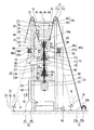
本実施形態の太陽熱発電設備は、図1に示すように、圧縮機11と、媒体加熱用受熱器46aと、タービン15と、排熱回収ボイラ30と、蒸気過熱用受熱器46bと、蒸気タービン25と、復水器40と、給水ポンプ45と、発電機21と、クラッチ60と、タワー64と、太陽光Rを目的の方向に反射する複数のヘリオスタット75と、を備える。
As shown in FIG. 1, the solar thermal power generation equipment of the present embodiment includes a
圧縮機11は、作動媒体としての空気を圧縮して圧縮媒体である圧縮空気を生成する。この圧縮機11は、鉛直方向に延びる圧縮機軸線Acを中心として回転する圧縮機ロータ12と、この圧縮機ロータ12を覆う圧縮機ケーシング13と、圧縮機ケーシング13内に外気を導く吸気ケーシング14と、を有する。
The
媒体加熱用受熱器46aは、ヘリオスタット75からの太陽光Rを受けて圧縮空気を加熱する。この媒体加熱用受熱器46aは、伝熱管47aと、この伝熱管47aを覆う受熱器ケーシング48aと、を有する。受熱器ケーシング48aの下方は開口している。伝熱管47aは、圧縮空気ライン(圧縮媒体ライン)82により、圧縮機11の吐出口と接続されている。
The medium
タービン15は、媒体加熱用受熱器46aで加熱された圧縮空気で駆動する。このタービン15は、鉛直方向に延びるタービン軸線Atを中心として回転するタービンロータ16と、このタービンロータ16を覆うタービンケーシング17と、を有する。タービンケーシング17の媒体入口は、加熱空気ライン(加熱媒体ライン)83により、媒体加熱用受熱器46aの伝熱管47aと接続されている。
The
ガスタービン10は、以上で説明した圧縮機11と、媒体加熱用受熱器46aと、タービン15と、を有して構成される。タービンロータ16と圧縮機ロータ12とは、機械的に直結され一体回転し、ガスタービンロータ19を構成する。また、タービンケーシング17と圧縮機ケーシング13とは、ガスタービンケーシングを構成する。
The
排熱回収ボイラ30は、タービン15から排気された高温の作動媒体である排気空気(排気媒体)で水を加熱し、この水を蒸気にする。排熱回収ボイラ30は、タービン15からの排気空気が内部を流れるボイラケーシング31と、このボイラケーシング31内に配置されている節炭器32及び過熱器34と、ボイラケーシング31内に一部が配置されている蒸発器33と、を有する。
The exhaust
蒸気過熱用受熱器46bは、ヘリオスタット75からの太陽光Rを受けて排熱回収ボイラ30からの蒸気を過熱する。この蒸気過熱用受熱器46bは、伝熱管47bと、この伝熱管47bを覆う受熱器ケーシング48bと、を有する。受熱器ケーシング48bの下方は開口している。伝熱管47bは、第一主蒸気ライン84により、排熱回収ボイラ30の過熱器34と接続されている。
The
蒸気タービン25は、排熱回収ボイラ30から蒸気過熱用受熱器46bを経てきた蒸気で駆動する。この蒸気タービン25は、鉛直方向に延びる蒸気タービン軸線Asを中心として回転する蒸気タービンロータ26と、この蒸気タービンロータ26を覆う蒸気タービンケーシング27と、蒸気タービンケーシング27からの蒸気を復水器40に導く排気ケーシング28と、を有する。蒸気タービンロータ26は、ガスタービンロータ19と機械的に接続されている。蒸気過熱用受熱器46bの伝熱管47bと蒸気タービンケーシング27とは、第二主蒸気ライン86で接続されている。この第二主蒸気ライン86には、ここを流れる蒸気の流量を調節する主蒸気調節弁87が設けられている。第一主蒸気ライン84と第二主蒸気ライン86とは、受熱器バイパスライン98で接続されている。この受熱器バイパスライン98には、受熱器バイパス弁98vが設けられている。
The
復水器40は、蒸気タービン25から排気された蒸気を水に戻す。この復水器40は、空冷式復水器である。この復水器40は、放熱部41と、貯水部44とを有する。放熱部41は、フィン付き伝熱管42と、ファン43と、を有する。フィン付き伝熱管42は、蒸気タービン25の排気ケーシング28に接続されている。第二主蒸気ライン86と、蒸気タービン25の排気ケーシング28又はフィン付き伝熱管42とは、蒸気タービンバイパスライン99で接続されている。この蒸気タービンバイパスライン99には、蒸気タービンバイパス弁99vが設けられている。
The
復水器40の貯水部44と排熱回収ボイラ30の節炭器32とは、給水ライン80で接続されている。この給水ライン80に給水ポンプ45が設けられている。
The
発電機21は、タービン15及び蒸気タービン25の駆動で発電する。発電機21は、鉛直方向に延びる発電機軸線Agを中心として回転する発電機ロータ22と、この発電機ロータ22を覆う発電機ケーシング23と、を有する。発電機ロータ22は、蒸気タービンロータ26と直結されている。
The
複数のロータ19,22,26のうち、少なくとも一のロータは、この一のロータのスラスト方向(鉛直方向)の移動を許容しつつ、この一のロータのラジアル方向の移動を規制するラジアル軸受63で支持されている。このラジアル軸受63は、タワー64に設けられている。
Of the plurality of
クラッチ60は、ガスタービンロータ19と蒸気タービンロータ26との間に配置され、両ロータ19,26を機械的に接続する。このクラッチ60は、ガスタービンロータ19と蒸気タービンロータ26との間で動力伝達可能な伝達状態と、ガスタービンロータ19と蒸気タービンロータ26との間で動力伝達が行われない非伝達状態とに、ガスタービンロータ19と蒸気タービンロータ26との間の接続状態を切り替える。
The clutch 60 is arranged between the
前述したように、発電機ロータ22は蒸気タービンロータ26と直結されている。よって、このクラッチ60は、ガスタービンロータ19と発電機ロータ22との間で、動力伝達可能な伝達状態と動力伝達が行われない非伝達状態とに、ガスタービンロータ19と発電機ロータ22との接続状態を切り替えるクラッチである、とも言える。
As described above, the
ヘリオスタット75は、太陽光Rを反射する反射鏡76と、反射鏡76を支持する支持脚77と、反射鏡76を目的の方向に向ける鏡駆動機78と、を有している。複数のヘリオスタット75は、タワー64の周りに設置されている。
The
タワー64は、圧縮機11、媒体加熱用受熱器46a、タービン15、排熱回収ボイラ30、蒸気過熱用受熱器46b、蒸気タービン25、クラッチ60、及び発電機21を支持する。タワー64は、鉛直方向に延びる複数の柱65と、複数の柱65を相互に接続する梁66と、を有する。柱65及び梁66は、例えば、鋼材で形成されている。
The
本実施形態では、圧縮機11、タービン15、排熱回収ボイラ30、蒸気タービン25、発電機21、復水器40の貯水部44は、それぞれ配列機器を成す。複数の配列機器は、鉛直方向に並んでいる。具体的に、本実施形態では、上から下に向って、排熱回収ボイラ30、タービン15、圧縮機11、蒸気タービン25、発電機21、復水器40の貯水部44の順で並んでいる。これらの複数の配列機器は、いずれも、タワー64を構成する複数の柱65で囲まれた領域内に配置されている。すなわち、配列機器は、タワー64内で、鉛直方向に並んでいる機器である。なお、配列機器は、その一部がタワー64からはみだしてもよい。
In the present embodiment, the
本実施形態の太陽熱発電設備は、さらに、複数の吊り下げワイヤ70と、複数のワイヤ支持機71と、複数の巻き取り機72と、を備える。吊り下げワイヤ70は、第一端70aと第二端70bとを有する。吊り下げワイヤ70の第一端70aは、タービンケーシング17に接続されている。ワイヤ支持機71は、支持ローラ71aと、この支持ローラ71aを回転可能に支持するローラ支持機71bと、を有する。ローラ支持機71bは、柱65の頂部に設けられている。巻き取り機72は、巻き取りドラム72aと、この巻き取りドラム72aを回転可能に維持するドラム支持機72bと、を有する。吊り下げワイヤ70の第二端70bは、巻き取りドラム72aに接続されている。支持ローラ71aは、吊り下げワイヤ70の第一端70aと第二端70bとの間を支持する。吊り下げワイヤ70の第二端70b側は、巻き取りドラム72aに巻き付いている。この巻き取りドラム72aに対する吊り下げワイヤ70の巻き付き量を変えることにより、ワイヤ支持機71から吊り下げワイヤ70の第一端70aまでの距離を変えることができる。つまり、本実施形態では、吊り下げワイヤ70の巻き付き量を変えることで、タービンケーシング17の鉛直方向の位置を変えることができる。
The solar thermal power generation facility of the present embodiment further includes a plurality of hanging
タービン15の排気口は、上向き開口している。このタービン15のタービンケーシング17には、排熱回収ボイラ30が機械的に接続されている。また、タービンロータ16には、圧縮機ロータ12、蒸気タービンロータ26及び発電機ロータ22が機械的に接続されている。このため、タービン15、排熱回収ボイラ30、圧縮機11、蒸気タービン25、及び発電機21は、吊り下げワイヤ70により、ワイヤ支持機71から吊り下げられている。従って、タービン15、排熱回収ボイラ30、圧縮機11、蒸気タービン25、及び発電機21は、吊り下げワイヤ70及びワイヤ支持機71を介して、タワー64に支持されている。復水器40は、タワー64の設置面に設置されている。
The exhaust port of the
媒体加熱用受熱器46aは、鉛直方向で圧縮機11が配置されている領域からタービン15が配置されている領域までの範囲内に配置されている。また、蒸気過熱用受熱器46bは、鉛直方向で排熱回収ボイラ30が配置されている領域から蒸気タービン25が配置されている領域までの範囲内に配置されている。媒体加熱用受熱器46aの受熱器ケーシング48a及び蒸気過熱用受熱器46bの受熱器ケーシング48bは、タワー64に固定されているブラケット49から吊り下げられている。
The medium
次に、以上で説明した太陽熱発電設備の動作について説明する。 Next, the operation of the solar thermal power generation facility described above will be described.
圧縮機11は、空気(作動媒体)を吸い込み、この空気を圧縮して圧縮空気(圧縮媒体)を生成する。この圧縮空気は、媒体加熱用受熱器46aの伝熱管47aに流入する。複数のヘリオスタット75のうちのいずれかのヘリオスタット75の鏡駆動機78は、反射鏡76で反射した太陽光Rが媒体加熱用受熱器46aに向うよう、反射鏡76の向きを調節する。この結果、ヘリオスタット75の反射鏡76で反射された太陽光Rは、媒体加熱用受熱器46aの受熱器ケーシング48aにおける開口を介して、媒体加熱用受熱器46aの伝熱管47aに照射される。伝熱管47a内を流れる圧縮空気は、伝熱管47aが受けた太陽光Rの熱により加熱される。
The
媒体加熱用受熱器46aで加熱された圧縮空気は、加熱空気ライン83を経て、タービンケーシング17内に流入する。タービンロータ16は、この圧縮空気により回転する。圧縮機ロータ12は、タービンロータ16に直結されているため、このタービンロータ16の回転と一体回転する。
The compressed air heated by the medium
タービンケーシング17から排気された高温の空気は、排気空気(排気媒体)として排熱回収ボイラ30のボイラケーシング31内に流入する。また、排熱回収ボイラ30の節炭器32には、給水ライン80から水が供給される。節炭器32では、排気空気と水とが熱交換され、水が加熱される。節炭器32で加熱された水は、排熱回収ボイラ30の蒸発器33に流入する。蒸発器33では、節炭器32からの水と排気空気とが熱交換され、水が加熱されて蒸気になる。この蒸気は、排熱回収ボイラ30の過熱器34に流入する。過熱器34では、この蒸気と排気空気とが熱交換され、蒸気が過熱される。
The high-temperature air exhausted from the
蒸気過熱用受熱器46bの伝熱管47bには、第一主蒸気ライン84を介して、排熱回収ボイラ30からの蒸気が流入する。複数のヘリオスタット75のうちのいずれかのヘリオスタット75の鏡駆動機78は、反射鏡76で反射した太陽光Rが蒸気過熱用受熱器46bに向うよう、反射鏡76の向きを調節する。この結果、ヘリオスタット75の反射鏡76で反射された太陽光Rは、蒸気過熱用受熱器46bの受熱器ケーシング48bにおける開口を介して、蒸気過熱用受熱器46bの伝熱管47bに照射される。伝熱管47b内を流れる蒸気は、伝熱管47bが受けた太陽光Rの熱により過熱される。
Steam from the exhaust
蒸気過熱用受熱器46bで過熱された蒸気は、第二主蒸気ライン86を経て、蒸気タービンケーシング27内に流入する。蒸気タービンロータ26は、この蒸気により回転する。
The steam superheated by the
タービンロータ16が回転し始め、排熱回収ボイラ30のボイラケーシング31内に高温の排気空気が流れ始めてから、蒸気タービン25の駆動に必要な流量の蒸気が発生するまでに、一定の時間を要する。このため、ガスタービン10の起動時、クラッチ60は、非伝達状態になり、ガスタービンロータ19と蒸気タービンロータ26及び発電機ロータ22との間で動力伝達が行われない。つまり、ガスタービン10の起動時、ガスタービンロータ19と蒸気タービンロータ26と発電機ロータ22とのうち、ガスタービンロータ19のみが単独で回転する。排熱回収ボイラ30で、蒸気タービン25の駆動に必要な流量の蒸気が発生し始めると、第二主蒸気ライン86に設けられている主蒸気調節弁87が開き、排熱回収ボイラ30からの蒸気が蒸気タービンケーシング27に流入する。さらに、排熱回収ボイラ30で、蒸気タービン25の駆動に必要な流量の蒸気が発生し始めると、クラッチ60が伝達状態になり、ガスタービンロータ19と蒸気タービンロータ26及び発電機ロータ22との間で動力伝達が行われる。つまり、ガスタービンロータ19と蒸気タービンロータ26と発電機ロータ22とが一体回転する。この結果、発電機21で発電が開始される。
It takes a certain amount of time from the start of rotation of the
以上のように、本実施形態の太陽熱発電設備は、クラッチ60を備えているため、ガスタービン10の起動時等において、ガスタービン10を単独で運転することができる。
As described above, since the solar thermal power generation facility of the present embodiment includes the clutch 60, the
蒸気タービン25から排気された蒸気は、復水器40のフィン付き伝熱管42内に、蒸気タービン25からの蒸気が流入する。ファン43は、フィン付き伝熱管42の外部からこのフィン付き伝熱管42に冷却用空気を送る。蒸気タービン25からの蒸気は、フィン付き伝熱管42内を流れる過程で、冷却用空気と熱交換されて、冷却され水になる。この水は、貯水部44に溜まる。貯水部44に溜まった水は、給水ポンプ45により昇圧されて、給水ライン80を介して、排熱回収ボイラ30の節炭器32に送られる。
The steam exhausted from the
本実施形態では、太陽熱発電設備を構成する複数の配列機器が、タワー64を構成する複数の柱65で囲まれた領域内に、鉛直方向に並んで配置されている。このため、本実施形態では、タワー64の二次元的な広がりを小さくすることができ、タワー64の占有面積を小さくすることができる。さらに、本実施形態では、太陽熱発電設備を構成する複数の機器をタワー64の最上段に配置する場合よりも、タワー64を構成する構造材に求められる強度を低くすることができる。しかも、本実施形態では、太陽熱発電設備を構成する複数の機器のうちで、運転時に最重量物となる復水器40の貯水部44を、複数の配列機器のうちで最も低い位置に配置し、この貯水部44をタワー64の設置面に設置している。このため、本実施形態では、タワー64を構成する構造材に求められる強度をより低くすることができる。よって、本実施形態では、タワー64の設備コストを抑えることができる。
In the present embodiment, a plurality of array devices constituting the solar thermal power generation facility are arranged vertically side by side in a region surrounded by a plurality of
本実施形態では、媒体加熱用受熱器46aが、鉛直方向で圧縮機11が配置されている領域からタービン15が配置されている領域までの範囲内に配置されている。このため、本実施形態では、媒体加熱用受熱器46aとタービン15とを接続する加熱空気ライン83の長さを短くすることができ、加熱空気ライン83からの熱放出を抑えることができる。また、本実施形態では、蒸気過熱用受熱器46bが、鉛直方向で排熱回収ボイラ30が配置されている領域から蒸気タービン25が配置されている領域までの範囲内に配置されている。このため、本実施形態では、排熱回収ボイラ30の過熱器34と蒸気過熱用受熱器46bとを接続する第一主蒸気ライン84の長さ、及び蒸気過熱用受熱器46bと蒸気タービン25とを接続する第二主蒸気ライン86の長さを短くすることができ、これらのラインからの熱放出を抑えることができる。
In the present embodiment, the medium
また、本実施形態では、タービン15、排熱回収ボイラ30、圧縮機11、蒸気タービン25、及び発電機21が、吊り下げワイヤ70により、ワイヤ支持機71から吊り下げられている。このため、これらの機器を点検又は修理する際、巻き取りドラム72aに巻き付いている吊り下げワイヤ70の巻き付き量を徐々に少なくして、各機器を下方に下げて、順次、機器を外すことで、比較的容易に各機器を点検又は修理することができる。
Further, in the present embodiment, the
「第二実施形態」
図2を参照して、太陽熱発電設備の第二実施形態について説明する。"Second embodiment"
A second embodiment of the solar thermal power generation facility will be described with reference to FIG.
本実施形態の太陽熱発電設備は、図2に示すように、第一実施形態の太陽熱発電設備と同様、圧縮機11と、媒体加熱用受熱器46aと、タービン15と、排熱回収ボイラ30aと、蒸気過熱用受熱器46bと、蒸気タービン25と、復水器40と、給水ポンプ45と、発電機21と、太陽光Rを目的の方向に反射する複数のヘリオスタット75と、タワー64と、を備える。本実施形態の太陽熱発電設備は、さらに、第一クラッチ61と、第二クラッチ62と、給水予熱用受熱器46cと、高温蓄熱器50aと、低温蓄熱器50bと、を備える。
As shown in FIG. 2, the solar thermal power generation equipment of the present embodiment includes a
本実施形態の圧縮機11、媒体加熱用受熱器46a、タービン15、蒸気過熱用受熱器46b、蒸気タービン25、復水器40、給水ポンプ45、発電機21、ヘリオスタット75は、第一実施形態の圧縮機11、媒体加熱用受熱器46a、タービン15、蒸気過熱用受熱器46b、蒸気タービン25、復水器40、給水ポンプ45、発電機21、ヘリオスタット75と同一構成である。
The
本実施形態の排熱回収ボイラ30aは、第一実施形態の排熱回収ボイラ30と同様、ボイラケーシング31と節炭器32と蒸発器33と過熱器34とを有する。本実施形態の排熱回収ボイラ30aは、さらに、媒体予熱器35を有する。媒体予熱器35は、圧縮空気ライン82中に設けられ、且つボイラケーシング31内に配置されている。
The exhaust
給水予熱用受熱器46cは、ヘリオスタット75からの太陽光Rを受けて給水ライン80を流れる水を加熱する。この給水予熱用受熱器46cは、伝熱管47cと、この伝熱管47cを覆う受熱器ケーシング48cと、を有する。受熱器ケーシング48cの下方は開口している。伝熱管47cは、給水ライン80中に設けられている。
The water
高温蓄熱器50aは、蒸気が内部を流れる蒸気伝熱管51aと、蓄熱体52及び蒸気伝熱管51aを覆う高温蓄熱ケーシング53aと、を有する。
The high-temperature
本実施形態の蓄熱体52は、例えば、硝酸ナトリウム、亜硝酸ナトリウム、硝酸カリウムの混合物から成る溶融塩である。この溶融塩の融点は、130〜170℃程度ある。この溶融塩の融点は、本実施形態の太陽熱発電設備内を流れる蒸気の温度よりも低い温度である。このため、本実施形態の蓄熱体52は、蒸気等との熱交換により加熱されると、流動性を示すようになる。なお、蓄熱体52は、上記溶融塩に限定されず、例えば、150℃程度以上で流動性を示す物であれば、基本的に如何なるものでもよい。
The
高温蓄熱器50aの蒸気伝熱管51aは、第二主蒸気ライン86から分岐している高温蒸気ライン92aに接続されている。高温蒸気ライン92aには、この高温蒸気ライン92aを流れる蒸気の流量を調節する高温蒸気調節弁93が設けられている。また、第二主蒸気ライン86で、高温蒸気ライン92aの分岐位置よりも蒸気流れの下流側で且つ第一主蒸気調節弁87よりも蒸気流れの上流側の位置には、この第二主蒸気ライン86を流れる蒸気の流量を調節する第二主蒸気調節弁85が設けられている。また、高温蓄熱器50aの蒸気伝熱管51aは、高温蒸気排気ライン94aにも接続されている。この高温蒸気排気ライン94aは、復水器40のフィン付き伝熱管42又は蒸気タービン25の排気ケーシング28に接続されている。また、本実施形態でも、第一主蒸気ライン84と第二主蒸気ライン86とは、受熱器バイパスライン98で接続されている。この受熱器バイパスライン98には、受熱器バイパス弁98vが設けられている。なお、ここでは、受熱器バイパスライン98の第一端を第一主蒸気ライン84に接続し、受熱器バイパスライン98の第二端を第二主蒸気ライン86に接続している。しかしながら、受熱器バイパスライン98の第一端を第一主蒸気ライン84に接続し、受熱器バイパスライン98の第二端を高温蒸気ライン92aに接続してもよい。
The steam
低温蓄熱器50bは、蒸気が内部を流れる蒸気伝熱管51bと、蓄熱体52及び蒸気伝熱管51bを覆う低温蓄熱ケーシング53bと、を有する。蒸気伝熱管51bは、復水器40のフィン付き伝熱管42又は蒸気タービン25の排気ケーシング28から分岐している低温蒸気ライン92bに接続されている。低温蒸気ライン92bには、この低温蒸気ライン92bを流れる蒸気の流量を調節する低温蒸気調節弁93bが設けられている。蒸気伝熱管51bは、低温蒸気排気ライン94bにも接続されている。この低温蒸気排気ライン94bは、復水器40のフィン付き伝熱管42又は貯水部44に接続されている。
The low-temperature
蒸気発生器55は、蓄熱体52が内部を流れる蓄熱体伝熱管56と、水を滞留させ且つ蓄熱体伝熱管56を覆う蒸気発生ケーシング57と、を有する。蓄熱体伝熱管56は、高温蓄熱体供給ライン95に接続されている。高温蓄熱体供給ライン95は、高温蓄熱ケーシング53aに接続されている。この高温蓄熱体供給ライン95には、高温蓄熱ケーシング53aからの蓄熱体52を昇圧する高温蓄熱体ポンプ54aが設けられている。蒸気発生ケーシング57は、給水ライン80から分岐している補助給水ライン88に接続されている。補助給水ライン88には、この補助給水ライン88を流れる水の流量を調節する補助給水調節弁89が設けられている。また、給水ライン80中で、補助給水ライン88の分岐位置よりも給水流れの下流側で給水予熱用受熱器46cよりも給水流れの下流側の位置には、この給水ライン80を流れる水の流量を調節する給水調節弁81が設けられている。蒸気発生ケーシング57には、補助蒸気ライン91が接続されている。この補助蒸気ライン91は、第二主蒸気ライン86中で、第二主蒸気調節弁85よりも蒸気流れの下流側で且つ第一主蒸気調節弁87よりも蒸気流れの上流側の位置に接続されている。
The
蒸気発生器55の蓄熱体伝熱管56は、高温蓄熱体排出ライン96に接続されている。この高温蓄熱体排出ライン96は、低温蓄熱ケーシング53bに接続されている。低温蓄熱ケーシング53bには、低温蓄熱体供給ライン97が接続されている。低温蓄熱体供給ライン97は、高温蓄熱ケーシング53aに接続されている。この低温蓄熱体供給ライン97には、低温蓄熱ケーシング53bからの蓄熱体52を昇圧する低温蓄熱体ポンプ54bが設けられている。
The heat storage body
本実施形態でも、圧縮機11、タービン15、排熱回収ボイラ30a、蒸気タービン25、発電機21、復水器40の貯水部44が、それぞれ配列機器を成す。本実施形態では、さらに、高温蓄熱器50a及び低温蓄熱器50bも、配列機器を成す。複数の配列機器は、鉛直方向に並んでいる。具体的に、本実施形態では、上から下に向って、高温蓄熱器50a、排熱回収ボイラ30a、タービン15、圧縮機11、発電機21、蒸気タービン25、低温蓄熱器50b、復水器40の貯水部44の順で並んでいる。これらの複数の配列機器は、いずれも、タワー64を構成する複数の柱65で囲まれた領域内に配置されている。なお、配列機器は、この領域から部分的にはみだしてもよい。
Also in this embodiment, the
本実施形態では、高温蓄熱器50a、排熱回収ボイラ30a、タービン15、圧縮機11、発電機21、及び蒸気タービン25が、吊り下げワイヤ70により、ワイヤ支持機71から吊り下げられている。従って、高温蓄熱器50a、排熱回収ボイラ30a、タービン15、圧縮機11、発電機21、及び蒸気タービン25は、吊り下げワイヤ70及びワイヤ支持機71を介して、タワー64に支持されている。復水器40は、第一実施形態と同様にタワー64の設置面に設置されている。また、低温蓄熱器50bは、復水器40の貯水部44に支持されている。また、蒸気発生器55は、本実施形態では、タワー64の外部に配置された図示されていない台により支持されている。なお、蒸気発生器55は、タワー64に支持されてもよい。
In the present embodiment, the high temperature
第一クラッチ61は、ガスタービンロータ19と発電機ロータ22との間に配置され、両ロータ19,22を機械的に接続する。この第一クラッチ61は、ガスタービンロータ19と発電機ロータ22との間で、動力伝達可能な伝達状態と動力伝達が行われない非伝達状態とに、ガスタービンロータ19と発電機ロータ22との間の接続状態を切り替える。
The first clutch 61 is arranged between the
第二クラッチ62は、蒸気タービンロータ26と発電機ロータ22との間に配置され、両ロータ26,22を機械的に接続する。この第二クラッチ62は、蒸気タービンロータ26と発電機ロータ22との間で、動力伝達可能な伝達状態と動力伝達が行われない非伝達状態とに、蒸気タービンロータ26と発電機ロータ22との間の接続状態を切り替える。
The second clutch 62 is arranged between the
媒体加熱用受熱器46aは、本実施形態では、鉛直方向で圧縮機11が配置されている領域から排熱回収ボイラ30aの媒体予熱器35が配置されている領域までの範囲内に配置されている。なお、媒体加熱用受熱器46aは、鉛直方向で圧縮機11が配置されている領域からタービン15が配置されている領域までの範囲内に配置されていることが好ましい。また、蒸気過熱用受熱器46bは、鉛直方向で排熱回収ボイラ30aが配置されている領域から蒸気タービン25が配置されている領域までの範囲内に配置されている。また、給水予熱用受熱器46cは、鉛直方向で復水器40の貯水部44が配置されている領域から排熱回収ボイラ30aが配置されている領域までの範囲内に配置されている。媒体加熱用受熱器46aの受熱器ケーシング48a、蒸気過熱用受熱器46bの受熱器ケーシング48b及び給水予熱用受熱器46cの受熱器ケーシング48cは、タワー64に固定されているブラケット49から吊り下げられている。
In the present embodiment, the medium
次に、以上で説明した本実施形態の太陽熱発電設備の動作について説明する。 Next, the operation of the solar thermal power generation facility of the present embodiment described above will be described.
本実施形態の圧縮機11も、第一実施形態の圧縮機11と同様、空気(作動媒体)を吸い込み、この空気を圧縮して圧縮空気(圧縮媒体)を生成する。この圧縮空気は、圧縮空気ライン82を介して、排熱回収ボイラ30aの媒体予熱器35内に流入する。媒体予熱器35は、タービン15からの排気空気と圧縮空気とを熱交換させ、圧縮空気を加熱する。媒体予熱器35で予熱された圧縮空気は、媒体加熱用受熱器46aの伝熱管47a内に流入し、ヘリオスタット75からの太陽光Rの熱より加熱される。
Like the
媒体加熱用受熱器46aで加熱された圧縮空気は、加熱空気ライン83を経て、タービンケーシング17内に流入する。タービンロータ16は、この圧縮空気により回転する。圧縮機ロータ12は、タービンロータ16に直結されているため、このタービンロータ16と一体回転する。
The compressed air heated by the medium
タービンケーシング17から排気された高温の空気は、排気空気として排熱回収ボイラ30aのボイラケーシング31内に流入する。また、排熱回収ボイラ30aでは、第一実施形態と同様に、復水器40から給水ライン80を介して供給された水が加熱されて蒸気になる。但し、本実施形態では、水が給水ライン80を流れる過程で、給水予熱用受熱器46cに水が流入し、ここで水が加熱される。この蒸気は、第一主蒸気ライン84を介して、蒸気過熱用受熱器46bの伝熱管47b内に流入する。この伝熱管47b内の蒸気は、ヘリオスタット75からの太陽光Rの熱により過熱される。
The high-temperature air exhausted from the
蒸気過熱用受熱器46bで過熱された蒸気は、第二主蒸気ライン86を経て、蒸気タービンケーシング27内に流入する。蒸気タービンロータ26は、この蒸気により回転する。
The steam superheated by the
本実施形態では、ガスタービン10の起動時、第一クラッチ61が伝達状態になっており、ガスタービンロータ19と発電機ロータ22との間で動力伝達が行われる。一方、ガスタービン10の起動時、第二クラッチ62が非伝達状態になっており、蒸気タービンロータ26と発電機ロータ22との間で動力伝達が行われない。よって、ガスタービン10の起動当初、発電機21は、ガスタービンロータ19の回転のみで発電する。排熱回収ボイラ30aで、蒸気タービン25の駆動に必要な流量の蒸気が発生し始めると、第二主蒸気ライン86に設けられている第一主蒸気調節弁87が開き、排熱回収ボイラ30aからの蒸気が蒸気タービンケーシング27に流れる。さらに、排熱回収ボイラ30aで、蒸気タービン25の駆動に必要な流量の蒸気が発生し始めると、第二クラッチ62が伝達状態になり、蒸気タービンロータ26及び発電機ロータ22との間で動力伝達が行われる。つまり、ガスタービンロータ19と蒸気タービンロータ26と発電機ロータ22とが一体回転する。この結果、発電機21は、ガスタービンロータ19及び蒸気タービンロータ26の回転で発電する。
In the present embodiment, when the
蒸気タービン25から排気された蒸気(排気蒸気)の一部は、第一実施形態と同様に、復水器40に送られ、この復水器40で水になる。また、蒸気タービン25から排気された蒸気の他の一部は、低温蒸気ライン92bを介して、低温蓄熱器50bの蒸気伝熱管51bに流入する。
A part of the steam (exhaust steam) exhausted from the
なお、太陽熱発電設備が以上の状態の際、高温蒸気ライン92aに設けられている高温蒸気調節弁93及び補助給水ライン88に設けられている補助給水調節弁89は全閉状態である。また、第二主蒸気ライン86に設けられている第二主蒸気調節弁85は全開状態である。さらに、給水ライン80に設けられている給水調節弁81は全開状態である。
When the solar thermal power generation facility is in the above state, the high temperature
排熱回収ボイラ30aから蒸気タービン25の駆動に十分な蒸気を蒸気タービン25に送っても、蒸気が余る場合には、高温蒸気ライン92aに設けられている高温蒸気調節弁93を開状態にする。この結果、排熱回収ボイラ30aからの蒸気のうちで、蒸気タービン25の駆動に十分な蒸気を除く余剰蒸気が高温蒸気ライン92aを介して、高温蓄熱器50aの蒸気伝熱管51aに流入する。蒸気伝熱管51aは、この蒸気伝熱管51a内の蒸気と蒸気伝熱管51a外の蓄熱体52とを熱交換させ、高温蓄熱ケーシング53a内の蓄熱体52を加熱する。この結果、蓄熱体52には余剰蒸気の熱が蓄えられる。蒸気伝熱管51a内の余剰蒸気は、高温蒸気排気ライン94aを介して、復水器40のフィン付き伝熱管42又は蒸気タービン25の排気ケーシング28に流入する。フィン付き伝熱管42又は蒸気タービン25の排気ケーシング28に流入した余剰蒸気は、フィン付き伝熱管42を通る過程で冷却されて水になってから、貯水部44に流入する。
Even if sufficient steam is sent from the exhaust
高温蓄熱ケーシング53a内の蓄熱体52が加熱され始めると、必要に応じて、この蓄熱体52は、高温蓄熱体供給ライン95、蒸気発生器55、及び高温蓄熱体排出ライン96を介して、低温蓄熱ケーシング53b内に送られる。また、低温蓄熱ケーシング53b内の蒸気伝熱管51bには、蒸気タービン25から排気された蒸気が流入する。蒸気伝熱管51b内の蒸気は、低温蓄熱ケーシング53b内の蓄熱体52と熱交換し、蓄熱体52を加熱する。この蒸気は、低温蒸気排気ライン94bを介して、復水器40の貯水部44内に流入する。低温蓄熱ケーシング53b内の蓄熱体52は、低温蓄熱体供給ライン97を介して、低温蓄熱体ポンプ54bにより、高温蓄熱ケーシング53a内に送られる。すなわち、蓄熱体52は、高温蓄熱ケーシング53a内と低温蓄熱ケーシング53b内との間で循環する。
When the
ガスタービン10の駆動で発電が行われる期間は、太陽が照っている期間のみである。言い換えると、太陽が照っていない期間では、ガスタービン10の駆動で発電を行うことはできない。
The period during which power is generated by driving the
本実施形態では、太陽が照っていない期間でも、発電を行えるようにするため、蓄熱体52を備える。
In the present embodiment, the
太陽が照らなくなると、給水ライン80に設けられている給水調節弁81を全閉状態にし、補助給水ライン88に設けられている補助給水調節弁89を全開状態にする。さらに、第二主蒸気ライン86に設けられている第二主蒸気調節弁85を全閉状態にする。さらに、高温蓄熱体ポンプ54a及び低温蓄熱体ポンプ54bを駆動し、蒸気で加熱された蓄熱体52を高温蓄熱ケーシング53a内と低温蓄熱ケーシング53b内との間で循環させる。この結果、蒸気発生器55の蓄熱体伝熱管56内には、高温蓄熱ケーシング53a内で加熱された蓄熱体52が高温蓄熱体供給ライン95を介して流入する。また、蒸気発生ケーシング57内には、復水器40の貯水部44に貯められた水が給水ライン80及び補助給水ライン88を介して流入する。蓄熱体伝熱管56は、この蓄熱体伝熱管56内の蓄熱体52と蓄熱体伝熱管56外の水とを熱交換させ、水を加熱し、この水を蒸気にする。この蒸気は、補助蒸気ライン91を介して、蒸気タービンケーシング27内に供給される。蒸気タービンロータ26は、この蒸気により回転する。この結果、発電機21は、蒸気タービン25の駆動のみで発電する。なお、この蒸気タービン25のみで発電する際、第一クラッチ61は非伝達状態になっており、ガスタービンロータ19と発電機ロータ22との間で動力伝達は行われない。一方、第二クラッチ62は伝達状態になっており、蒸気タービンロータ26と発電機ロータ22との間で動力伝達が行われる。よって、蒸気タービン25のみの駆動で発電する際には、ガスタービンロータ19を回転させる必要がなく、蒸気タービン25による発電効率を高めることができる。
When the sun stops shining, the water
蒸気発生器55での蓄熱体52と水との熱交換により、蓄熱体52に蓄えられていた熱の量は、次第に少なくなる。このため、蒸気発生器55から蒸気タービン25へ蒸気を供給し始めてから所定時間経過すると、蒸気タービン25の駆動に十分な蒸気を蒸気発生器55から蒸気タービン25へ送ることができなくなる。よって、蒸気タービン25の駆動に十分な蒸気を排熱回収ボイラ30aからも蒸気発生器55からも蒸気タービン25へ送ることができなくなると、第一主蒸気調節弁87が閉じ、蒸気タービン25の駆動は停止する。
Due to the heat exchange between the
太陽が照っている期間、ガスタービン10及び蒸気タービン25が駆動する。しかしながら、太陽が照っている期間、発電機21での発電量に対する外部からの要求が少ない場合がある。この場合、本実施形態では、蒸気タービン25を駆動させず、ガスタービン10のみを駆動させて、このガスタービン10のみの駆動で発電する。
The
この場合、給水調節弁81及び補助給水調節弁89を全閉状態にして、排熱回収ボイラ30aや蒸気発生器55に水が供給されないようにする。さらに、第一クラッチ61を伝達状態にして、ガスタービンロータ19と発電機ロータ22との間で動力伝達が行われるようにする。一方、第二クラッチ62を非伝達状態にして、蒸気タービンロータ26と発電機ロータ22との間で動力伝達が行われないようにする。よって、ガスタービン10のみの駆動で発電する際には、蒸気タービンロータ26を回転させる必要がなく、ガスタービン10による発電効率を高めることができる。
In this case, the water
なお、ガスタービン10の駆動のみで発電する場合、給水調節弁81を開けて、排熱回収ボイラ30aに水が供給されるようにしてもよい。この場合、第二主蒸気調節弁85を全閉状態にして、高温蒸気調節弁93を全開状態にする。排熱回収ボイラ30aに供給された水は、この排熱回収ボイラ30aでタービン15から排気された排気空気により加熱されて蒸気になる。この蒸気は、高温蒸気ライン92aを介して、高温蓄熱器50aの蒸気伝熱管51aに流入する。蒸気伝熱管51aは、この蒸気伝熱管51a内の蒸気と蒸気伝熱管51a外の蓄熱体52とを熱交換させ、高温蓄熱ケーシング53a内の蓄熱体52を加熱する。この結果、蓄熱体52には蒸気の熱が蓄えられる。また、高温蓄熱器50aの蒸気伝熱管51a内の蒸気は、高温蒸気排気ライン94a、フィン付き伝熱管42又は排気ケーシング28、及び低温蒸気ライン92bを介して、低温蓄熱器50bの蒸気伝熱管51bに流入する。蒸気伝熱管51bは、この蒸気伝熱管51b内の蒸気と蒸気伝熱管51b外の蓄熱体52とを熱交換させ、低温蓄熱ケーシング53b内の蓄熱体52を加熱する。この結果、蓄熱体52にも蒸気の熱が蓄えられる。すなわち、ガスタービン10の駆動のみで発電する場合も、蓄熱体52に対する蓄熱動作を実行してもよい。
When power is generated only by driving the
以上のように、本実施形態では、太陽が照っていない期間でも、発電を行える。さらに、本実施形態では、ガスタービン10のみ駆動でも、蒸気タービン25のみの駆動でも、ガスタービン10及び蒸気タービン25の両者の駆動でも、発電することが可能である。よって、本実施形態では、外部からの発電量の要求が大きく変化した場合でも、この発電量の要求に対応することができる。
As described above, in the present embodiment, power generation can be performed even during a period when the sun is not shining. Further, in the present embodiment, it is possible to generate electricity by driving only the
また、本実施形態でも、第一実施形態と同様に、太陽熱発電設備を構成する複数の配列機器が、タワー64を構成する複数の柱65で囲まれた領域内で、鉛直方向に並んで配置されている。このため、本実施形態でも、タワー64の占有面積を小さくすることができると共に、タワー64を構成する構造材に求められる強度を低くすることができ、タワー64の設備コストを抑えることができる。
Further, also in the present embodiment, as in the first embodiment, a plurality of array devices constituting the solar thermal power generation facility are arranged side by side in the vertical direction in the area surrounded by the plurality of
なお、本実施形態で、給水ライン80の一部を低温蓄熱ケーシング53bと高温蓄熱ケーシング53aとのうち、少なくとも一方の蓄熱ケーシングに通してもよい。この場合、給水ライン80の一部を蓄熱ケーシングに通して、この蓄熱ケーシング内の蓄熱体52と接触させることで、給水ライン80を通る水を蓄熱体52の熱で予熱することができる。
In this embodiment, a part of the
また、本実施形態では、複数の配列機器が、上から下に向って、高温蓄熱器50a、排熱回収ボイラ30a、タービン15、圧縮機11、発電機21、蒸気タービン25、低温蓄熱器50b、復水器40の貯水部44の順で並んでいる。しかしながら、複数の配列機器の並び順は以上の通りでなくてもよい。
Further, in the present embodiment, a plurality of arranged devices, from top to bottom, have a
具体的には、複数の配列機器は、例えば、上から下に向って、以下の(1)〜(7)のいずれかの順で並んでいてもよい。
(1)高温蓄熱器50a→蒸気タービン25→発電機21→排熱回収ボイラ30a→タービン15→圧縮機11→低温蓄熱器50b→貯水部44
(2)排熱回収ボイラ30a→タービン15→圧縮機11→蒸気タービン25→発電機21→高温蓄熱器50a→低温蓄熱器50b→貯水部44
(3)排熱回収ボイラ30a→タービン15→圧縮機11→高温蓄熱器50a→低温蓄熱器50b→発電機21→蒸気タービン25→貯水部44
(4)圧縮機11→タービン15→排熱回収ボイラ30a→発電機21→高温蓄熱器50a→低温蓄熱器50b→蒸気タービン25→貯水部44
(5)高温蓄熱器50a→低温蓄熱器50b→発電機21→排熱回収ボイラ30a→タービン15→圧縮機11→蒸気タービン25→貯水部44
(6)排熱回収ボイラ30a→タービン15→圧縮機11→発電機21→蒸気タービン25→高温蓄熱器50a→低温蓄熱器50b→貯水部44
(7)高温蓄熱器50a→低温蓄熱器50b→排熱回収ボイラ30a→タービン15→圧縮機11→発電機21→蒸気タービン25→貯水部44Specifically, the plurality of array devices may be arranged in any of the following orders (1) to (7) from top to bottom, for example.
(1) High temperature
(2) Exhaust
(3) Exhaust
(4)
(5) High temperature
(6) Exhaust
(7) High temperature
本実施形態における複数の配列機器の配列順、及び、以上で例示した複数の配列機器の配列順で共通する点は、貯水部44が複数の配列機器のうちで最も下方に配置されている点である。これは、第一実施形態の説明で説明したように、太陽熱発電設備を構成する複数の機器のうちで、復水器40の貯水部44が運転時に最重量物となるからである。
What is common to the arrangement order of the plurality of arrangement devices in the present embodiment and the arrangement order of the plurality of arrangement devices exemplified above is that the
以上のように、復水器40の貯水部44を最も下方に配置することが好ましい関係上、基本的に、復水器40に蒸気を排出する蒸気タービン25をガスタービン10より復水器40に近い側、つまりガスタービン10より下方に配置することが好ましい。
As described above, since it is preferable to arrange the
ガスタービン10からの排気空気で蒸気を発生させる排熱回収ボイラ30aは、ガスタービン10を構成する圧縮機11やタービン15よりも軽い。このため、ガスタービン10を構成する圧縮機11やタービン15よりも排熱回収ボイラ30aを上に配置することが好ましい。さらに、ガスタービン10のうちで排気空気を排熱回収ボイラ30aに送るのは、タービン15である。このタービン15から排気される排気空気(排気媒体)は、高温であるため自然対流により上昇する。よって、圧縮機11よりもタービン15を上に配置し、その上に排熱回収ボイラ30aを配置することが好ましい。
The exhaust
また、発電形態の多様性を図るために、第一クラッチ61及び第二クラッチ62を設ける場合には、本実施形態の配列順や以上の(1)(3)(4)(6)(7)の例示配列順のように、発電機21を基準にして、圧縮機11及びタービン15を鉛直方向上側と鉛直方向下側とのうちの一方側に配置し、蒸気タービン25を鉛直方向上側と鉛直方向下側とのうちの他方側に配置することが好ましい。
Further, when the first clutch 61 and the second clutch 62 are provided in order to increase the variety of power generation forms, the arrangement order of the present embodiment and the above (1) (3) (4) (6) (7) ), The
また、先に説明した第一実施形態や後述する第三及び第四実施形態の太陽熱発電設備での複数の配列機器の配列順を、本実施形態における複数の配列機器の配列順、及び、以上で例示した複数の配列機器の配列順のいずれかにしてもよい。但し、第一実施形態や後述する第三及び第四実施形態の太陽熱発電設備は、高温蓄熱器50a及び低温蓄熱器50bがない。このため、第一実施形態や後述する第三及び第四実施形態の太陽熱発電設備での複数の配列機器の配列順として、本実施形態における複数の配列機器の配列順、及び、以上で例示した複数の配列機器の配列順のいずれかを採用する場合、高温蓄熱器50a及び低温蓄熱器50bを省いた配列順にする。
In addition, the arrangement order of the plurality of arranged devices in the solar thermal power generation facilities of the first embodiment described above and the third and fourth embodiments described later, the arrangement order of the plurality of arranged devices in the present embodiment, and the above. It may be any of the arrangement order of the plurality of arrangement devices illustrated in. However, the solar thermal power generation facilities of the first embodiment and the third and fourth embodiments described later do not have the high temperature
「第三実施形態」
図3及び図4を参照して、太陽熱発電設備の第三実施形態について説明する。"Third embodiment"
A third embodiment of the solar thermal power generation facility will be described with reference to FIGS. 3 and 4.
本実施形態の太陽熱発電設備は、第一実施形態の太陽熱発電設備の変形例である。本実施形態の太陽熱発電設備は、図3に示すように、第一実施形態の太陽熱発電設備と同様、排熱回収ボイラ30と、タービン15と、圧縮機11と、クラッチ60と、蒸気タービン25と、発電機21と、復水器40と、媒体加熱用受熱器46aと、蒸気過熱用受熱器46bと、給水ポンプ45と、複数のヘリオスタット75と、タワー64aと、を備える。但し、本実施形態のタワー64aは、第一実施形態のタワー64と異なる。
The solar thermal power generation facility of the present embodiment is a modification of the solar thermal power generation facility of the first embodiment. As shown in FIG. 3, the solar thermal power generation facility of the present embodiment has an exhaust
本実施形態のタワー64aは、鉛直方向に延びる仮想軸Avを中心として円筒状を成している。このタワー64aは、図4に示すように、例えばコンクリートで形成されている第一構造体67と、この第一構造体67の外周を囲む鋼板等で形成されている第二構造体68と、第二構造体68の外周の一部を覆う断熱材69と、を備える。第一構造体67は、タワー64aの形状と同様に、前述の仮想軸Avを中心として円筒状を成している。第二構造体68は、円筒状の第一構造体67の内周面及び外周面に接するように配置されている。すなわち、鋼板等の第二構造体68は、第一構造体67を形成するコンクリートの枠として機能している。断熱材69は、少なくとも、外周側の第二構造体68の外周面に接するよう配置されている。なお、断熱材69は、さらに、内周側の第二構造体68の内周面に接するよう配置されてもよい。
The
コンクリートは、蓄熱性が高い。このため、コンクリートを蓄熱体として用いる。よって、本実施形態のタワー64aの第一構造体67は、蓄熱体で形成されている。
Concrete has a high heat storage property. Therefore, concrete is used as a heat storage body. Therefore, the
本実施形態でも、第一実施形態と同様、排熱回収ボイラ30、タービン15、圧縮機11、蒸気タービン25、発電機21、復水器40の貯水部44のそれぞれは、配列機器を成す。これら配列機器は、円筒状のタワー64a内で鉛直方向に並んで配置されている。
In the present embodiment as well, as in the first embodiment, each of the exhaust
排熱回収ボイラ30の過熱器34と蒸気過熱用受熱器46bとを接続する第一主蒸気ライン84の一部、蒸気過熱用受熱器46bと蒸気タービン25とを接続する第二主蒸気ライン86の一部、圧縮機11と媒体加熱用受熱器46aとを接続する圧縮空気ライン82の一部、媒体加熱用受熱器46aとタービン15とを接続する加熱空気ライン83の一部、給水ライン80の一部は、いずれも、タワー64aの第一構造体67内を通り、この第一構造体67に接している。
A part of the first
本実施形態では、第一主蒸気ライン84を流れる蒸気の温度が蓄熱体である第一構造体67の温度より高い場合、蒸気の熱が第一構造体67に蓄えられる。逆に、第一主蒸気ライン84を流れる蒸気の温度が第一構造体67の温度より低い場合、第一構造体67に蓄えられた熱により蒸気が過熱される。同様に、第二主蒸気ライン86を流れる蒸気の温度が第一構造体67の温度より高い場合、蒸気の熱が第一構造体67に蓄えられる。逆に、第二主蒸気ライン86を流れる蒸気の温度が第一構造体67の温度より低い場合、第一構造体67に蓄えられた熱により蒸気が過熱される。このため、天候の変動等で、排熱回収ボイラ30からの蒸気の温度が変動しても、さらに、蒸気過熱用受熱器46bからの蒸気の温度が変動しても、蒸気と蓄熱体である第一構造体67との間での熱の流れにより、蒸気タービン25に供給される蒸気の温度の急激な変動を抑え、予め定められた蒸気条件を保持することができる。このため、本実施形態では、天候の変動等があっても、蒸気タービン25の出力を安定化させることができる。
In the present embodiment, when the temperature of the steam flowing through the first
本実施形態において、圧縮空気ライン82を流れる空気の温度が蓄熱体である第一構造体67の温度より高い場合、空気の熱が第一構造体67に蓄えられる。逆に、圧縮空気ライン82を流れる空気の温度が第一構造体67の温度より低い場合、第一構造体67に蓄えられた熱により空気が加熱される。また、加熱空気ライン83を流れる空気の温度は、基本的に第一構造体67の温度より高い。このため、この加熱空気ライン83を流れる空気の熱の一部が、第一構造体67に蓄えられる。以上のように、第一構造体67に蓄えられた熱は、主として、第一主蒸気ライン84及び第二主蒸気ライン86を流れる蒸気の過熱に利用される。本実施形態では、天候の変動等で、媒体加熱用受熱器46aからの空気の温度が変動しても、この空気と第一構造体67との間での熱の流れにより、タービン15に流入する空気の急激な温度変動を抑えることができる。この結果、本実施形態では、ガスタービン10の出力を安定化させることができる。
In the present embodiment, when the temperature of the air flowing through the
給水ライン80を流れる水の温度は、蓄熱体である第一構造体67の温度より低い。このため、給水ライン80を流れる水は、第一構造体67に蓄えらえた熱により予熱されてから、排熱回収ボイラ30内に流入する。このため、本実施形態では、排熱回収ボイラ30で効率的に蒸気を発生させることができる。
The temperature of the water flowing through the
以上のように、本実施形態では、天候の変動等があっても、ガスタービン10や蒸気タービン25を安定運転することができる。また、本実施形態では、排熱回収ボイラ30で効率的に蒸気を発生させることができる。
As described above, in the present embodiment, the
さらに、本実施形態でも、第一実施形態と同様に、太陽熱発電設備を構成する複数の配列機器が、タワー64a内で、鉛直方向に並んで配置されている。このため、本実施形態でも、タワー64aの占有面積を小さくすることができると共に、タワー64aを構成する構造材に求められる強度を低くすることができ、タワー64aの設備コストを抑えることができる。
Further, also in the present embodiment, as in the first embodiment, a plurality of array devices constituting the solar thermal power generation facility are arranged side by side in the vertical direction in the
「第四実施形態」
図5を参照して、太陽熱発電設備の第四実施形態について説明する。"Fourth embodiment"
A fourth embodiment of the solar thermal power generation facility will be described with reference to FIG.
本実施形態の太陽熱発電設備は、第三実施形態の太陽熱発電設備の変形例である。本実施形態の太陽熱発電設備は、図5に示すように、第三実施形態の太陽熱発電設備に、蒸気発生器55aを追加したものである。
The solar thermal power generation facility of the present embodiment is a modification of the solar thermal power generation facility of the third embodiment. As shown in FIG. 5, the solar thermal power generation facility of the present embodiment is obtained by adding a
本実施形態の蒸気発生器55aは、水が流れる第一伝熱管58aと、第一伝熱管58aからの水が流入する蒸気ドラム59と、蒸気ドラム59内で発生した蒸気が流れる第二伝熱管58bと、蓄熱体である第一構造体67の一部とを有する。第一伝熱管58a及び第二伝熱管58bは、いずれも、第一構造体67内を通り、この第一構造体67に接している。
The
第一伝熱管58aは、給水ライン80から分岐している補助給水ライン88に接続されている。このため、第一伝熱管58a内には、復水器40の貯水部44に貯められた水が給水ライン80及び補助給水ライン88を介して流入する。補助給水ライン88には、この補助給水ライン88を流れる水の流量を調節する補助給水調節弁89が設けられている。また、給水ライン80中で、補助給水ライン88の分岐位置よりも給水流れの下流側で且つ排熱回収ボイラ30よりも給水流れの下流側の位置には、この給水ライン80を流れる水の流量を調節する給水調節弁81が設けられている。第二伝熱管58bには、補助蒸気ライン91が接続されている。この補助蒸気ライン91は、第二主蒸気ライン86中で、主蒸気調節弁87よりも蒸気流れの上流側の位置に接続されている。
The first heat transfer tube 58a is connected to an auxiliary
本実施形態でも、第三実施形態と同様に、排熱回収ボイラ30の過熱器34と蒸気過熱用受熱器46bとを接続する第一主蒸気ライン84の一部、蒸気過熱用受熱器46bと蒸気タービン25とを接続する第二主蒸気ライン86の一部、圧縮機11と媒体加熱用受熱器46aとを接続する圧縮空気ライン82の一部、媒体加熱用受熱器46aとタービン15とを接続する加熱空気ライン83の一部、給水ライン80の一部は、いずれも、タワー64aの第一構造体67内を通り、この第一構造体67に接している。このため、蓄熱体である第一構造体67は、第一主蒸気ライン84及び第二主蒸気ライン86を流れる蒸気により蓄熱される場合がある。また、第一構造体67は、圧縮空気ライン82及び加熱空気ライン83を流れる空気により蓄熱される場合もある。
Also in the present embodiment, as in the third embodiment, a part of the first
本実施形態でも、蒸気タービン25のみの駆動で発電を行うことができる。蒸気タービン25のみの駆動で発電を行う場合、クラッチ60を非伝達状態にして、ガスタービンロータ19と蒸気タービンロータ26及び発電機ロータ22との間で動力伝達が行われないようにする。なお、クラッチ60が非接続状態でも、蒸気タービンロータ26と発電機ロータ22とは機械的に直結されているため、蒸気タービンロータ26の回転で発電機ロータ22は回転する。蒸気タービン25のみの駆動で発電を行う場合、さらに、給水調節弁81を全閉状態にする一方で、補助給水調節弁89を全開状態にする。
Also in this embodiment, power generation can be performed by driving only the
蒸気発生器55aの一部を構成する第一伝熱管58aには、給水ライン80及び補助給水ライン88を介して、復水器40の貯水部44からの水が流入する。第一伝熱管58aは、第一伝熱管58a内を流れる水と第一伝熱管58a外の蓄熱体である第一構造体67とを熱交換させ、水を加熱して、この水を蒸気にする。この蒸気は、蒸気発生器55aの一部を構成する第二伝熱管58b内に流入する。第二伝熱管58bは、第二伝熱管58b内を流れる蒸気と第二伝熱管58b外の蓄熱体である第一構造体67とを熱交換させ、蒸気を過熱する。第二伝熱管58b内で過熱された蒸気は、補助蒸気ライン91及び第二主蒸気ライン86を介して、蒸気タービンケーシング27内に流入する。蒸気タービンロータ26は、この蒸気により回転する。この結果、発電機21は、蒸気タービンロータ26の回転に伴う発電機ロータ22の回転で発電する。
Water from the
以上のように、蓄熱体である第一構造体67を蒸気発生器55aの構成要素にしても、第一構造体67に蓄熱された熱で蒸気を発生させ、この蒸気で蒸気タービン25を駆動させることができる。
As described above, even if the
なお、本実施形態でも、第二実施形態のように、蒸気タービン25から排気された蒸気の熱も蓄熱体である第一構造体67に蓄熱させてもよい。
In this embodiment as well, as in the second embodiment, the heat of the steam exhausted from the
また、本実施形態及び第三実施形態のタワー64aは、鉛直方向に延びる仮想軸Avを中心として円筒状を成している。しかしながら、タワーは、複数の柱で構成しても、複数の壁で構成してもよい。タワーを複数の柱で構成する場合、各柱を第一構造体67と第二構造体68と断熱材69とで形成する。また、タワーを複数の壁で構成する場合、各壁を第一構造体67と第二構造体68と断熱材69とで形成する。
Further, the
また、本実施形態でも、第二実施形態の説明で説明したように、発電機21を基準にして、圧縮機11及びタービン15を鉛直方向上側と鉛直方向下側とのちの一方側に配置し、蒸気タービン25を鉛直方向上側と鉛直方向下側とのうちの他方側に配置してもよい。この場合、ガスタービンロータ19と発電機ロータ22との間に第二実施形態で説明した第一クラッチ61を配置し、発電機ロータ22と蒸気タービンロータ26との間に第二実施形態で説明した第二クラッチ62を配置する。このように、第一クラッチ61及び第二クラッチ62を配置することで、本実施形態でも、第二実施形態と同様に、ガスタービン10のみ駆動でも、蒸気タービン25のみの駆動でも、ガスタービン10及び蒸気タービン25の両者の駆動でも、発電機21で発電させることが可能になる。
Further, also in the present embodiment, as described in the description of the second embodiment, the
「第五実施形態」
図6を参照して、太陽熱発電設備の第五実施形態について説明する。"Fifth embodiment"
A fifth embodiment of the solar thermal power generation facility will be described with reference to FIG.
本実施形態の太陽熱発電設備は、第一実施形態の太陽熱発電設備の変形例である。本実施形態の太陽熱発電設備は、図6に示すように、第一実施形態の太陽熱発電設備と同様、排熱回収ボイラ30と、タービン15と、圧縮機11と、クラッチ60と、蒸気タービン25と、発電機21と、復水器40と、媒体加熱用受熱器46aと、蒸気過熱用受熱器46bと、給水ポンプ45と、複数のヘリオスタット75と、タワー64と、を備える。本実施形態の太陽熱発電設備は、さらに、循環ライン36と、圧力調節機構36aと、媒体補給ライン38と、媒体補給弁39と、を備える。
The solar thermal power generation facility of the present embodiment is a modification of the solar thermal power generation facility of the first embodiment. As shown in FIG. 6, the solar thermal power generation facility of the present embodiment has an exhaust
圧縮機ケーシング13は、作動媒体が流入する本体入口13iを有する。圧縮機11の吸気ケーシング14は、この本体入口13iに接続されている。この吸気ケーシング14は、作動媒体が流入する吸気入口14iを有する。タービンケーシング17は、作動媒体を排気するタービン出口17oを有する。ボイラケーシング31は、タービン15からの作動媒体が流入するボイラ入口31iと、この作動媒体を排気するボイラ排出口31oと、を有する。タービン出口17oとボイラ入口31iとは接続されている。
The
循環ライン36は、排熱回収ボイラ30のボイラ排出口31oと圧縮機11の吸気入口14iとを接続する。この循環ライン36は、排熱回収ボイラ30のボイラ排出口31oから排出された作動媒体を、吸気ケーシング14を介して圧縮機ケーシング13内に導く。よって、ガスタービンケーシング、ボイラケーシング31及び循環ライン36等を有して、作動媒体の循環系統が形成される。
The
圧力調節機構36aは、循環ライン36に設けられている。この圧力調節機構36aは、循環ライン36内の圧力を調節する。この圧力調節機構36aは、例えば、ダンパである。
The
媒体補給ライン38は、循環ライン36に接続されている。媒体補給弁39は、この媒体補給ライン38に設けられている。前述の循環系統内の作動媒体の量が少なくなると、媒体補給弁39を開けて、媒体補給ライン38から循環系統内に作動媒体を補給する。
The
第一から第四実施形態における作動媒体は、空気である。本実施形態の作動媒体は、この空気よりも蒸発温度が低い低沸点媒体である。低沸点媒体としては、例えば、CO2や有機ランキンサイクルに使用される媒体等がある。有機ランキンサイクルに使用される媒体としては、例えば、以下の物質がある。
・トリクロロエチレン、テトラクロロエチレン、モノクロロベンゼン、ジクロロベンゼン、パーフルオロデカリン等の有機ハロゲン化合物
・ブタン、プロパン、ペンタン、ヘキサン、ヘプタン、オクタン、デカン等のアルカン
・シクロペンタン、シクロヘキサン等の環状アルカン
・チオフェン、ケトン、芳香族化合物
・R134a、R245fa等の冷媒、
・以上を組み合わせたものThe working medium in the first to fourth embodiments is air. The working medium of the present embodiment is a low boiling point medium having a lower evaporation temperature than this air. Examples of the low boiling point medium include CO 2 and a medium used for the organic Rankine cycle. Examples of the medium used in the organic Rankine cycle include the following substances.
-Organic halogen compounds such as trichlorethylene, tetrachloroethylene, monochlorobenzene, dichlorobenzene and perfluorodecalin-Alkanes such as butane, propane, pentane, hexane, heptane, octane and decane-Cyclic alkanes such as cyclopentane and cyclohexane-Thiophene, ketone, Aromatic compounds ・ refrigerants such as R134a and R245fa,
・ A combination of the above
本実施形態では、圧縮機11が排熱回収ボイラ30から排気された作動媒体を吸い込むので、圧縮機11が吸い込む作動媒体の温度は、以上の実施形態のように圧縮機11が作動媒体として外気を吸い込む場合よりも高くなる。さらに、本実施形態では、圧縮機11が排熱回収ボイラ30から排気された作動媒体を吸い込むので、圧縮機11が吸い込む作動媒体の圧力を、以上の実施形態のように圧縮機11が作動媒体として外気を吸い込む場合よりも高くすることができる。
In the present embodiment, since the
よって、本実施形態では、以上の実施形態よりも、高温且つ高圧の作動媒体をタービン15に供給することができる。このため、本実施形態では、以上の実施形態よりもガスタービン出力を高めることができる。
Therefore, in the present embodiment, a high temperature and high pressure working medium can be supplied to the
また、本実施形態では、作動媒体として、空気よりも蒸発温度が低い低沸点媒体を用いている。このため、作動媒体のタービン出口温度が作動媒体として空気を用いている場合と同じでも、圧力調節機構36aで循環ライン36内の圧力を調節することで、作動媒体の相が気相になっている温度域を広くすることができる。よって、気相の作動媒体からエネルギーを得るにあたり、本実施形態では、作動媒体として空気を用いる場合よりも、エネルギー落差を大きくすることができる。このため、本実施形態では、この観点からも、以上の実施形態よりもガスタービン出力を高めることができる。
Further, in the present embodiment, a low boiling point medium having a lower evaporation temperature than air is used as the working medium. Therefore, even if the turbine outlet temperature of the working medium is the same as when air is used as the working medium, the phase of the working medium becomes a gas phase by adjusting the pressure in the
なお、本実施形態において、吸気ケーシング14が循環ラインの一部であるとすると、この循環ラインは、圧縮機ケーシング13の本体入口13iに直接接続されていることになる。また、本実施形態において、ボイラケーシング31が循環ラインの一部であるとすると、この循環ラインは、タービン出口17oに直接接続されていことになる。また、本実施形態において、排熱回収ボイラ30は、無くてもよい。この場合、タービン出口17oと、吸気ケーシング14の吸気入口14i又は圧縮機ケーシング13の本体入口13iとが、循環ラインにより直接接続されることになる。
In the present embodiment, assuming that the
また、本実施形態の作動媒体は、低沸点媒体でなく空気であってもよい。但し、本実施形態において、作動媒体として空気を用いた場合、作動媒体として低沸点媒体を用いることによるメリットを得ることができなくなる。但し、本実施形態では、タービン15から排気された高温の作動媒体を圧縮機11が吸い込むことにより、タービン15から排気された高温の作動媒体の大気放出を抑えることができる。このため、本実施形態で、作動媒体として空気を用いた場合、例えば、現在問題になっているビル空調用室外機からの排熱等に起因したヒートアイランド現象を抑制することができる。
Further, the working medium of the present embodiment may be air instead of the low boiling point medium. However, in the present embodiment, when air is used as the working medium, the merit of using the low boiling point medium as the working medium cannot be obtained. However, in the present embodiment, the
また、本実施形態の変形例として、図7に示すように、本実施形態の太陽熱発電設備に給水予熱器37を追加してもよい。この給水予熱器37は、給水ライン80を流れる水と循環ライン36を流れる作動媒体とを熱交換させ、給水ライン80から排熱回収ボイラ30の節炭器32に流入する水を加熱させる。
Further, as a modification of the present embodiment, as shown in FIG. 7, a
また、本実施形態では、第一実施形態の変形例であるが、第二〜第四実施形態も、本実施形態と同様に、循環ラインを追加すると共に、作動媒体を低沸点媒体にしてもよい。 Further, in the present embodiment, although it is a modification of the first embodiment, in the second to fourth embodiments, as in the present embodiment, a circulation line is added and the working medium is a low boiling point medium. Good.
「変形例」
以上の各実施形態の太陽熱発電設備は、いずいれも、蒸気過熱用受熱器46bを備えている。しかしながら、この蒸気過熱用受熱器46bは省略されてもよい。また、第二実施形態の太陽熱発電設備は、給水予熱用受熱器46cを備えている。しかしながら、この給水予熱用受熱器46cは、省略されてもよい。"Modification example"
All of the solar thermal power generation facilities of the above embodiments are provided with a
以上の各実施形態の復水器40は、いずれも空冷式である。しかしながら、復水器は水冷式であってもよい。
The
第一実施形態、第三実施形態、第四実施形態、及び第五実施形態の排熱回収ボイラ30は、第二実施形態の排熱回収ボイラ30と同様に、媒体予熱器35を有してもよい。
The exhaust
以上の各実施形態では、ガスタービン軸線Atと蒸気タービン軸線Asと発電機軸線Agとが同一直線上に位置する。しかしながら、例えば、ガスタービンロータ19と発電機ロータ22との間にクラッチ又は変速機を設けた場合や、蒸気タービン25と発電機ロータ22との間にクラッチ又は変速機を設けた場合には、各軸線は互いに平行であるものの、同一直線上に位置しなくなることがある。このため、各軸線は、それぞれが鉛直方向に延び、互いに平行であれば、同一直線上に位置しなくてもよい。
In each of the above embodiments, the gas turbine axis At, the steam turbine axis As, and the generator axis Ag are located on the same straight line. However, for example, when a clutch or a transmission is provided between the
以上の各実施形態では、タービンケーシング17に吊り下げワイヤ70の第一端70aを接続している。しかしながら、機器の配列によっては、圧縮機ケーシング13、蒸気タービンケーシング27、発電機ケーシング23のうちのいずれか一のケーシングに吊り下げワイヤ70の第一端70aを接続してもよい。また、タービンケーシング17、圧縮機ケーシング13、蒸気タービンケーシング27、発電機ケーシング23のうちのいずれか一のケーシングに複数の第一吊り下げワイヤ70の第一端70aのそれぞれを接続し、他の一のケーシングに複数の第二吊り下げワイヤの第一端のそれぞれを接続して、複数の第一吊り下げワイヤ70と複数の第二吊り下げワイヤが共同して、タービン15や蒸気タービン25等を吊り下げてもよい。また、以上の各実施形態では、吊り下げワイヤ70を用いて、ガスタービン10等をタワー64,64aから吊り下げ支持している。しかしながら、吊り下げワイヤ70を用いるのは、主として、点検又は修理を考慮したためであるため、ガスタービン10等をタワー64,64aで支持できれば、他の方法でガスタービン10等を支持してもよい。例えば、タワー64,64aにブラケットを固定し、このブラケットにガスタービン10を取り付けてもよい。
In each of the above embodiments, the
本発明の一態様によれば、タワーの占有面積を小さくでき、且つタワーの設備コストを抑えることができる。 According to one aspect of the present invention, the occupied area of the tower can be reduced and the equipment cost of the tower can be suppressed.
10:ガスタービン
11:圧縮機
12:圧縮機ロータ
13:圧縮機ケーシング
13i:本体入口
14:吸気ケーシング
14i:吸気入口
15:タービン
16:タービンロータ
17:タービンケーシング
17o:タービン出口
19:ガスタービンロータ
21:発電機
22:発電機ロータ
23:発電機ケーシング
25:蒸気タービン
26:蒸気タービンロータ
27:蒸気タービンケーシング
28:排気ケーシング
30,30a:排熱回収ボイラ
31:ボイラケーシング
31i:ボイラ入口
31o:ボイラ排出口
32:節炭器
33:蒸発器
34:過熱器
35:媒体予熱器
36:循環ライン
36a:圧力調節機構
37:給水予熱器
38:媒体補給ライン
39:媒体補給弁
40:復水器
41:放熱部
42:フィン付き伝熱管
43:ファン
44:貯水部
45:給水ポンプ
46a:媒体加熱用受熱器
47a:伝熱管
48a:受熱器ケーシング
49:ブラケット
46b:蒸気過熱用受熱器
47b:伝熱管
48b:受熱器ケーシング
46c:給水予熱用受熱器
47c:伝熱管
48c:受熱器ケーシング
50a:高温蓄熱器
51a:蒸気伝熱管
52:蓄熱体
53a:高温蓄熱ケーシング
54a:高温蓄熱体ポンプ
50b:低温蓄熱器
51b:蒸気伝熱管
53b:低温蓄熱ケーシング
54b:低温蓄熱体ポンプ
55,55a:蒸気発生器
56:蓄熱体伝熱管
57:蒸気発生ケーシング
58a:第一伝熱管
58b:第二伝熱管
59:蒸気ドラム
60:クラッチ
61:第一クラッチ
62:第二クラッチ
63:ラジアル軸受
64,64a:タワー
65:柱
66:梁
67:第一構造体
68:第二構造体
69:断熱材
70:吊り下げワイヤ
70a:第一端
70b:第二端
71:ワイヤ支持機
71a:支持ローラ
71b:ローラ支持機
72:巻き取り機
72a:巻き取りドラム
72b:ドラム支持機
75:ヘリオスタット
76:反射鏡
77:支持脚
78:鏡駆動機
80:給水ライン
81:給水調節弁
82:圧縮空気ライン
83:加熱空気ライン
84:第一主蒸気ライン
85:第二主蒸気調節弁
86:第二主蒸気ライン
87:主蒸気調節弁(第一主蒸気調節弁)
88:補助給水ライン
89:補助給水調節弁
91:補助蒸気ライン
92a:高温蒸気ライン
92b:低温蒸気ライン
93:高温蒸気調節弁
93b:低温蒸気調節弁
94a:高温蒸気排気ライン
94b:低温蒸気排気ライン
95:高温蓄熱体供給ライン
96:高温蓄熱体排出ライン
97:低温蓄熱体供給ライン
98:受熱器バイパスライン
98v:受熱器バイパス弁
99:蒸気タービンバイパスライン
99v:蒸気タービンバイパス弁
R:太陽光
Ac:圧縮機軸線
At:タービン軸線
Ag:発電機軸線
As:蒸気タービン軸線
Av:仮想軸10: Gas turbine 11: Compressor 12: Compressor rotor 13: Compressor casing 13i: Main body inlet 14: Intake casing 14i: Intake inlet 15: Turbine 16: Turbine rotor 17: Turbine casing 17o: Turbine outlet 19: Gas turbine rotor 21: Generator 22: Generator rotor 23: Generator casing 25: Steam turbine 26: Steam turbine rotor 27: Steam turbine casing 28: Exhaust casing 30, 30a: Exhaust heat recovery boiler 31: Boiler casing 31i: Boiler inlet 31o: Boiler outlet 32: Coal saving device 33: Evaporator 34: Superheater 35: Medium preheater 36: Circulation line 36a: Pressure adjustment mechanism 37: Water supply preheater 38: Medium replenishment line 39: Medium replenishment valve 40: Water recovery device 41: Heat radiating part 42: Heat transfer tube with fin 43: Fan 44: Water storage part 45: Water supply pump 46a: Heat receiver for medium heating 47a: Heat transfer tube 48a: Heat receiver casing 49: Bracket 46b: Heat receiver for steam overheating 47b: Transfer Heat tube 48b: Heat receiver casing 46c: Water supply preheater heat receiver 47c: Heat transfer tube 48c: Heat receiver casing 50a: High temperature heat storage device 51a: Steam heat transfer tube 52: Heat storage body 53a: High temperature heat storage casing 54a: High temperature heat storage body pump 50b: Low temperature Heat storage device 51b: Steam heat transfer tube 53b: Low temperature heat storage casing 54b: Low temperature heat storage body pump 55, 55a: Steam generator 56: Heat storage body heat transfer tube 57: Steam generation casing 58a: First heat transfer tube 58b: Second heat transfer tube 59: Steam drum 60: Clutch 61: First clutch 62: Second clutch 63: Radial bearing 64, 64a: Tower 65: Pillar 66: Beam 67: First structure 68: Second structure 69: Insulation material 70: Suspended Wire 70a: First end 70b: Second end 71: Wire support machine 71a: Support roller 71b: Roller support machine 72: Winding machine 72a: Winding drum 72b: Drum support machine 75: Heliostat 76: Reflector 77: Support leg 78: Mirror drive machine 80: Water supply line 81: Water supply control valve 82: Compressed air line 83: Heating air line 84: First main steam line 85: Second main steam control valve 86: Second main steam line 87: Main steam control valve (first main steam control valve)
88: Auxiliary water supply line 89: Auxiliary water supply control valve 91:
Claims (14)
太陽光を受けて前記圧縮媒体を加熱する受熱器である媒体加熱用受熱器と、
前記媒体加熱用受熱器で加熱された前記圧縮媒体で駆動するタービンと、
前記タービンの駆動で発電する発電機と、
前記タービンから排気された作動媒体である排気媒体で水を加熱して、前記水を蒸気にする排熱回収ボイラと、
前記排熱回収ボイラからの蒸気で駆動する蒸気タービンと、
前記蒸気タービンから排気された蒸気を水に戻す復水器と、
前記復水器内の水を前記排熱回収ボイラに導く給水ラインと、
前記排熱回収ボイラからの蒸気の熱を蓄える蓄熱体と、
前記給水ラインから分岐している補助給水ラインと、
前記補助給水ラインに接続され、前記蓄熱体に接して前記補助給水ラインからの水と前記蓄熱体との間で熱交換させる伝熱管を有し、前記蓄熱体で前記水を加熱して、前記水を蒸気にする蒸気発生器と、
前記蒸気発生器で発生した蒸気を前記蒸気タービンに導く補助蒸気ラインと、
前記圧縮機、前記媒体加熱用受熱器、前記タービン及び前記発電機を支持するタワーと、
を備え、
前記圧縮機は、鉛直方向に延びる圧縮機軸線を中心として回転する圧縮機ロータと、前記圧縮機ロータを覆う圧縮機ケーシングと、を有し、
前記タービンは、鉛直方向に延びるタービン軸線を中心として回転するタービンロータと、前記タービンロータを覆うタービンケーシングと、を有し、
前記圧縮機ロータと前記タービンロータとは、機械的に接続されてガスタービンロータを構成し、
前記発電機は、前記ガスタービンロータと機械的に接続され、鉛直方向に延びる発電機軸線を中心として回転する発電機ロータと、前記発電機ロータを覆う発電機ケーシングと、を有し、
前記圧縮機、前記タービン及び前記発電機は、それぞれ、配列機器を成し、
複数の前記配列機器は、鉛直方向に並んでいる、
太陽熱発電設備。 A compressor that compresses the working medium to produce a compression medium,
A medium heating receiver, which is a heat receiver that receives sunlight to heat the compression medium,
A turbine driven by the compression medium heated by the medium heating receiver and
A generator that generates electricity by driving the turbine,
An exhaust heat recovery boiler that heats water with an exhaust medium, which is an exhaust medium exhausted from the turbine, to steam the water.
A steam turbine driven by steam from the exhaust heat recovery boiler,
A condenser that returns the steam exhausted from the steam turbine to water,
A water supply line that guides the water in the condenser to the exhaust heat recovery boiler,
A heat storage body that stores the heat of steam from the exhaust heat recovery boiler,
Auxiliary water supply line branching from the water supply line and
It has a heat transfer tube that is connected to the auxiliary water supply line and is in contact with the heat storage body to exchange heat between the water from the auxiliary water supply line and the heat storage body, and the water is heated by the heat storage body to obtain the above. A steam generator that turns water into steam,
An auxiliary steam line that guides the steam generated by the steam generator to the steam turbine,
The compressor, the heat receiver for heating the medium, the turbine, and the tower supporting the generator.
With
The compressor has a compressor rotor that rotates about a compressor axis extending in the vertical direction, and a compressor casing that covers the compressor rotor.
The turbine has a turbine rotor that rotates about a turbine axis extending in the vertical direction, and a turbine casing that covers the turbine rotor.
The compressor rotor and the turbine rotor are mechanically connected to form a gas turbine rotor.
The generator has a generator rotor that is mechanically connected to the gas turbine rotor and rotates about a generator axis extending in the vertical direction, and a generator casing that covers the generator rotor.
The compressor, the turbine, and the generator each form an array device.
The plurality of the array devices are arranged in the vertical direction.
Solar thermal power generation equipment.
太陽光を受けて前記圧縮媒体を加熱する受熱器である媒体加熱用受熱器と、
前記媒体加熱用受熱器で加熱された前記圧縮媒体で駆動するタービンと、
前記タービンの駆動で発電する発電機と、
前記タービンから排気された作動媒体である排気媒体で水を加熱して、前記水を蒸気にする排熱回収ボイラと、
前記排熱回収ボイラからの蒸気で駆動する蒸気タービンと、
前記蒸気タービンから排気された蒸気を水に戻す復水器と、
前記復水器内の水を前記排熱回収ボイラに導く給水ラインと、
前記排熱回収ボイラからの蒸気の熱を蓄え、流動性を有する蓄熱体を有する蓄熱器と、
前記給水ラインから分岐している補助給水ラインと、
前記補助給水ラインに接続され、前記補助給水ラインからの水を加熱して、前記水を蒸気にする蒸気発生器と、
前記蒸気発生器で発生した蒸気を前記蒸気タービンに導く補助蒸気ラインと、
前記蓄熱器と前記蒸気発生器とを接続し、前記蓄熱器からの前記蓄熱体が流れる蓄熱体供給ラインと、
前記圧縮機、前記媒体加熱用受熱器、前記タービン及び前記発電機を支持するタワーと、
を備え、
前記蓄熱器は、前記排熱回収ボイラからの蒸気が流れる蒸気伝熱管と、前記蓄熱体及び前記蒸気伝熱管を収納する蓄熱ケーシングと、を有し、
前記蒸気発生器は、前記蓄熱体供給ラインに接続され、前記蓄熱体供給ラインからの前記蓄熱体が流れる蓄熱体伝熱管と、前記補助給水ラインに接続され、前記補助給水ラインからの水を滞留させ且つ前記蓄熱体伝熱管を覆う蒸気発生ケーシングと、を有し、
前記圧縮機は、鉛直方向に延びる圧縮機軸線を中心として回転する圧縮機ロータと、前記圧縮機ロータを覆う圧縮機ケーシングと、を有し、
前記タービンは、鉛直方向に延びるタービン軸線を中心として回転するタービンロータと、前記タービンロータを覆うタービンケーシングと、を有し、
前記圧縮機ロータと前記タービンロータとは、機械的に接続されてガスタービンロータを構成し、
前記発電機は、前記ガスタービンロータと機械的に接続され、鉛直方向に延びる発電機軸線を中心として回転する発電機ロータと、前記発電機ロータを覆う発電機ケーシングと、を有し、
前記圧縮機、前記タービン及び前記発電機は、それぞれ、配列機器を成し、
複数の前記配列機器は、鉛直方向に並んでいる、
太陽熱発電設備。 A compressor that compresses the working medium to produce a compression medium,
A medium heating receiver, which is a heat receiver that receives sunlight to heat the compression medium,
A turbine driven by the compression medium heated by the medium heating receiver and
A generator that generates electricity by driving the turbine,
An exhaust heat recovery boiler that heats water with an exhaust medium, which is an exhaust medium exhausted from the turbine, to steam the water.
A steam turbine driven by steam from the exhaust heat recovery boiler,
A condenser that returns the steam exhausted from the steam turbine to water,
A water supply line that guides the water in the condenser to the exhaust heat recovery boiler,
A heat storage device that stores the heat of steam from the exhaust heat recovery boiler and has a fluid heat storage body,
Auxiliary water supply line branching from the water supply line and
A steam generator that is connected to the auxiliary water supply line and heats the water from the auxiliary water supply line to steam the water.
An auxiliary steam line that guides the steam generated by the steam generator to the steam turbine,
A heat storage body supply line that connects the heat storage device and the steam generator and allows the heat storage body to flow from the heat storage device.
The compressor, the heat receiver for heating the medium, the turbine, and the tower supporting the generator.
With
The heat storage device has a steam heat transfer tube through which steam from the exhaust heat recovery boiler flows, and a heat storage casing for accommodating the heat storage body and the steam heat transfer tube.
The steam generator is connected to the heat storage body supply line, is connected to the heat storage body heat transfer tube through which the heat storage body flows from the heat storage body supply line, and is connected to the auxiliary water supply line, and retains water from the auxiliary water supply line. And has a steam generation casing that covers the heat storage body heat transfer tube.
The compressor has a compressor rotor that rotates about a compressor axis extending in the vertical direction, and a compressor casing that covers the compressor rotor.
The turbine has a turbine rotor that rotates about a turbine axis extending in the vertical direction, and a turbine casing that covers the turbine rotor.
The compressor rotor and the turbine rotor are mechanically connected to form a gas turbine rotor.
The generator has a generator rotor that is mechanically connected to the gas turbine rotor and rotates about a generator axis extending in the vertical direction, and a generator casing that covers the generator rotor.
The compressor, the turbine, and the generator each form an array device.
The plurality of the array devices are arranged in the vertical direction.
Solar thermal power generation equipment.
前記蓄熱器は、配列機器を成し、
前記蓄熱器を含む複数の前記配列機器は、鉛直方向に並んでいる、
太陽熱発電設備。 In the solar thermal power generation facility according to claim 2.
The heat storage device forms an array device.
The plurality of array devices including the heat storage device are arranged in the vertical direction.
Solar thermal power generation equipment.
前記蓄熱器である高温蓄熱器の他に、低温蓄熱器を備え、
前記低温蓄熱器は、前記蒸気タービンから排気された蒸気の一部が流れる蒸気伝熱管と、蓄熱体及び前記低温蓄熱器の前記蒸気伝熱管を収納する蓄熱ケーシングと、を有し、
前記低温蓄熱器の前記蒸気伝熱管は、前記復水器に接続され、
前記高温蓄熱器及び前記低温蓄熱器は、鉛直方向に並んでいる、
太陽熱発電設備。 In the solar thermal power generation facility according to claim 3.
In addition to the high-temperature heat storage device, which is the heat storage device, a low-temperature heat storage device is provided.
The low-temperature heat storage device includes a steam heat transfer tube through which a part of steam exhausted from the steam turbine flows, and a heat storage casing for accommodating a heat storage body and the steam heat transfer tube of the low-temperature heat storage device.
The steam heat transfer tube of the low temperature regenerator is connected to the condenser.
The high-temperature heat storage device and the low-temperature heat storage device are arranged in the vertical direction.
Solar thermal power generation equipment.
前記圧縮機ケーシングは、前記作動媒体が流入する入口を有し、前記排熱回収ボイラは、前記排気媒体である前記作動媒体を排出する排出口を有し、
前記排熱回収ボイラの前記排出口から排出された前記作動媒体を、前記圧縮機ケーシングの前記入口から前記圧縮機ケーシング内に導く循環ラインを備える、
太陽熱発電設備。 In the solar thermal power generation facility according to any one of claims 1 to 4 .
The compressor casing has an inlet into which the working medium flows in, and the exhaust heat recovery boiler has an exhaust port for discharging the working medium, which is the exhaust medium.
A circulation line for guiding the working medium discharged from the discharge port of the exhaust heat recovery boiler from the inlet of the compressor casing into the compressor casing is provided.
Solar thermal power generation equipment.
前記循環ラインに設けられ、前記循環ライン内の圧力を調節する圧力調節機構を備える、
太陽熱発電設備。 In the solar thermal power generation facility according to claim 5 .
A pressure adjusting mechanism provided in the circulation line and adjusting the pressure in the circulation line is provided.
Solar thermal power generation equipment.
前記排熱回収ボイラは、配列機器を成し、
前記排熱回収ボイラを含む複数の前記配列機器は、鉛直方向に並んでいる、
太陽熱発電設備。 In solar thermal power generation facility according to any one of claims 1 or et 6,
The exhaust heat recovery boiler forms an array device.
The plurality of array devices including the exhaust heat recovery boiler are arranged in the vertical direction.
Solar thermal power generation equipment.
前記蒸気タービンは、鉛直方向に延びる蒸気タービン軸線を中心として回転する蒸気タービンロータと、前記蒸気タービンロータを覆う蒸気タービンケーシングと、を有し、
前記蒸気タービンは、配列機器を成し、
前記蒸気タービンを含む複数の前記配列機器は、鉛直方向に並んでいる、
太陽熱発電設備。 In solar thermal power generation facility according to any one of claims 1 or et 7,
The steam turbine has a steam turbine rotor that rotates about a steam turbine axis extending in the vertical direction, and a steam turbine casing that covers the steam turbine rotor.
The steam turbine forms an array device and
The plurality of array devices including the steam turbine are arranged in the vertical direction.
Solar thermal power generation equipment.
前記蒸気タービンロータは、前記発電機ロータに機械的に接続され、
前記ガスタービンロータと前記発電機ロータとの間で、動力伝達可能な伝達状態と動力伝達が行われない非伝達状態とに、前記ガスタービンロータと前記発電機ロータとの接続状態を切り替えるクラッチを備える、
太陽熱発電設備。 In the solar thermal power generation facility according to claim 8 .
The steam turbine rotor is mechanically connected to the generator rotor and
A clutch that switches the connection state between the gas turbine rotor and the generator rotor between the gas turbine rotor and the generator rotor in a transmission state in which power can be transmitted and a non-transmission state in which power transmission is not performed. Prepare, prepare
Solar thermal power generation equipment.
前記圧縮機及び前記タービンは、前記発電機を基準にして、鉛直方向上側と鉛直方向下側とのちの一方側に配置され、
前記蒸気タービンは、前記発電機を基準にして、鉛直方向上側と鉛直方向下側とのうちの他方側に配置され、
前記蒸気タービンロータと前記発電機ロータとの間で、動力伝達可能な伝達状態と動力伝達が行われない非伝達状態とに、前記蒸気タービンロータと前記発電機ロータとの接続状態を切り替えるクラッチを備える、
太陽熱発電設備。 In the solar thermal power generation facility according to claim 9 .
The compressor and the turbine are arranged on one side of the upper side in the vertical direction and the lower side in the vertical direction with reference to the generator.
The steam turbine is arranged on the other side of the upper side in the vertical direction and the lower side in the vertical direction with reference to the generator.
A clutch that switches the connection state between the steam turbine rotor and the generator rotor between a transmission state in which power can be transmitted and a non-transmission state in which power transmission is not performed between the steam turbine rotor and the generator rotor. Prepare, prepare
Solar thermal power generation equipment.
前記復水器は、前記蒸気タービンから排気された蒸気が水に戻った後に、前記水が貯えられる貯水部を有し、
前記貯水部は、配列機器を成し、
前記貯水部を含む複数の前記配列機器は、鉛直方向に並んでいる、
太陽熱発電設備。 In solar thermal power generation facility according to any one of claims 1 or et 10,
The condenser has a water storage unit in which the water is stored after the steam exhausted from the steam turbine returns to water.
The water storage unit forms an array device,
The plurality of array devices including the water storage unit are arranged in the vertical direction.
Solar thermal power generation equipment.
前記タービンは、前記圧縮機よりも上方に配置され、
前記排熱回収ボイラは、前記タービンより上方に配置されている、
太陽熱発電設備。 In solar thermal power generation facility according to any one of claims 1 or et 11,
The turbine is located above the compressor and
The exhaust heat recovery boiler is arranged above the turbine.
Solar thermal power generation equipment.
前記タワーは、前記配列機器を支えるための複数の構造体を有し、
複数の前記構造体のうち、一の構造体は、前記蓄熱体で形成されている、
太陽熱発電設備。 In the solar thermal power generation facility according to claim 1,
The tower has a plurality of structures for supporting the array equipment, and has a plurality of structures.
Of the plurality of the structures, one structure is formed of the heat storage body.
Solar thermal power generation equipment.
太陽光を反射する反射鏡と、前記反射鏡で反射した太陽光が前記受熱器に向うよう前記反射鏡の向きを変える鏡駆動機と、を有するヘリオスタットを備える、
太陽熱発電設備。 In solar thermal power generation facility according to any one of claims 1 or et 13,
A heliostat comprising a reflector that reflects sunlight and a mirror drive that redirects the reflector so that the sunlight reflected by the reflector faces the heat receiver.
Solar thermal power generation equipment.
Applications Claiming Priority (3)
| Application Number | Priority Date | Filing Date | Title |
|---|---|---|---|
| JP2017136191 | 2017-07-12 | ||
| JP2017136191 | 2017-07-12 | ||
| PCT/JP2018/025336 WO2019013066A1 (en) | 2017-07-12 | 2018-07-04 | Solar thermal power generation facility |
Publications (2)
| Publication Number | Publication Date |
|---|---|
| JPWO2019013066A1 JPWO2019013066A1 (en) | 2020-07-16 |
| JP6812552B2 true JP6812552B2 (en) | 2021-01-13 |
Family
ID=65002597
Family Applications (1)
| Application Number | Title | Priority Date | Filing Date |
|---|---|---|---|
| JP2019529080A Active JP6812552B2 (en) | 2017-07-12 | 2018-07-04 | Solar thermal power generation equipment |
Country Status (3)
| Country | Link |
|---|---|
| US (1) | US11060424B2 (en) |
| JP (1) | JP6812552B2 (en) |
| WO (1) | WO2019013066A1 (en) |
Families Citing this family (3)
| Publication number | Priority date | Publication date | Assignee | Title |
|---|---|---|---|---|
| US11174843B2 (en) * | 2017-09-22 | 2021-11-16 | Mitsubishi Power, Ltd. | Solar thermal power generation equipment including wind turbine on the same vertically oriented shaft |
| JP7599283B2 (en) * | 2020-05-21 | 2024-12-13 | 三菱重工業株式会社 | High-temperature water supply equipment |
| CN112815527A (en) * | 2020-12-31 | 2021-05-18 | 海南自贸区浩天能环境工程有限公司 | Multi-energy supply end energy-saving water purifying water boiler |
Family Cites Families (16)
| Publication number | Priority date | Publication date | Assignee | Title |
|---|---|---|---|---|
| JPS54155336A (en) * | 1978-05-27 | 1979-12-07 | Jiyuntarou Yamada | Solar energy power plant |
| DE3037574A1 (en) * | 1980-10-04 | 1982-07-22 | M.A.N. Maschinenfabrik Augsburg-Nürnberg AG, 8000 München | Solar-powered electrical generator - has absorber, generator turbine and compressor formed as single unit supported by mast |
| JP3898847B2 (en) * | 1998-12-01 | 2007-03-28 | 株式会社竹中工務店 | Thermal power plant |
| JP2010285965A (en) * | 2009-06-15 | 2010-12-24 | Mitsubishi Heavy Ind Ltd | Solar gas turbine power generator |
| US8327641B2 (en) * | 2009-12-01 | 2012-12-11 | General Electric Company | System for generation of power using solar energy |
| JP2012047086A (en) | 2010-08-26 | 2012-03-08 | Sumitomo Electric Ind Ltd | Electric power generation system |
| DE102010042792A1 (en) * | 2010-10-22 | 2012-04-26 | Man Diesel & Turbo Se | System for generating mechanical and / or electrical energy |
| JP2012140872A (en) | 2010-12-28 | 2012-07-26 | Mitsubishi Heavy Ind Ltd | Solar heat gas turbine and power generating equipment |
| JP2012202390A (en) | 2011-03-28 | 2012-10-22 | Mitsubishi Heavy Ind Ltd | Turbine facility, and solar thermal power generation facility equipped with the same |
| US20130081395A1 (en) | 2011-09-29 | 2013-04-04 | General Electric Company | System and method for generating electric power |
| JP2013096304A (en) * | 2011-10-31 | 2013-05-20 | Mitsubishi Heavy Ind Ltd | Solar heat turbine electricity generation device and control method therefor |
| JP2013133766A (en) * | 2011-12-27 | 2013-07-08 | Mitsubishi Heavy Ind Ltd | Solar energy gas turbine |
| JP2014001641A (en) * | 2012-06-15 | 2014-01-09 | Tokyo Institute Of Technology | Solar gas turbine power generation system |
| US9322295B2 (en) | 2012-10-17 | 2016-04-26 | General Electric Company | Thermal energy storage unit with steam and gas turbine system |
| JP2014088821A (en) | 2012-10-30 | 2014-05-15 | Mitsui Eng & Shipbuild Co Ltd | Solar heat power generation plant and control method of the same |
| JP7014661B2 (en) * | 2018-03-29 | 2022-02-01 | 三菱重工業株式会社 | Boiler plant and its operation method |
-
2018
- 2018-07-04 JP JP2019529080A patent/JP6812552B2/en active Active
- 2018-07-04 WO PCT/JP2018/025336 patent/WO2019013066A1/en not_active Ceased
- 2018-07-04 US US16/629,450 patent/US11060424B2/en active Active
Also Published As
| Publication number | Publication date |
|---|---|
| JPWO2019013066A1 (en) | 2020-07-16 |
| WO2019013066A1 (en) | 2019-01-17 |
| US20200182094A1 (en) | 2020-06-11 |
| US11060424B2 (en) | 2021-07-13 |
Similar Documents
| Publication | Publication Date | Title |
|---|---|---|
| JP6812552B2 (en) | Solar thermal power generation equipment | |
| CN102318096B (en) | Solar thermal system | |
| US20140138959A1 (en) | Solar combined cycle power systems | |
| JP6302481B2 (en) | Concentrating solar power plant and method | |
| JP2011117447A (en) | Power generation system using solar energy | |
| GR20180100563A (en) | AUTOMATIC STORAGE SYSTEM OF WIND AND PHOTOVOLTAIC ENERGY FOR UNINTERRUPTED ELECTRICITY PRODUCTION AND PROVISION OF ENERGY AUTONOMY | |
| CN102859190A (en) | Solar thermal power plant | |
| JP3218262U (en) | Heating medium heating device | |
| KR101579004B1 (en) | The power generation system using solar energy | |
| JP7096109B2 (en) | Solar thermal power generation equipment | |
| WO2013098945A1 (en) | Solar thermal power generation apparatus | |
| JP6857740B2 (en) | Solar thermal power generation equipment | |
| WO2013065492A1 (en) | Solar heat turbine electricity generation device and control method therefor | |
| CN105247208B (en) | Solar thermal collector factory with storage heater | |
| JP2016540913A (en) | Power generator with gear-integrated steam compressor | |
| JP7599283B2 (en) | High-temperature water supply equipment | |
| US20150007567A1 (en) | Plant and method for increasing the efficiency of electric energy production | |
| JP7199323B2 (en) | steam turbine generator | |
| JP6712672B1 (en) | Power generation device and power generation system using supercritical CO2 gas | |
| JP2012202390A (en) | Turbine facility, and solar thermal power generation facility equipped with the same | |
| CN116857034A (en) | Organic Rankine cycle power generation system and method for megawatt offshore platform | |
| JP2016099099A (en) | Drying system | |
| CN107676759A (en) | Solar power station live (open) steam overheats generation method and equipment | |
| CN206234797U (en) | Solar power station live (open) steam crosses the equipment of being thermally generated | |
| WO2014065158A1 (en) | Combined power generation plant |
Legal Events
| Date | Code | Title | Description |
|---|---|---|---|
| A521 | Request for written amendment filed |
Free format text: JAPANESE INTERMEDIATE CODE: A523 Effective date: 20200109 |
|
| A621 | Written request for application examination |
Free format text: JAPANESE INTERMEDIATE CODE: A621 Effective date: 20200109 |
|
| A131 | Notification of reasons for refusal |
Free format text: JAPANESE INTERMEDIATE CODE: A131 Effective date: 20200811 |
|
| A521 | Request for written amendment filed |
Free format text: JAPANESE INTERMEDIATE CODE: A523 Effective date: 20200917 |
|
| TRDD | Decision of grant or rejection written | ||
| A01 | Written decision to grant a patent or to grant a registration (utility model) |
Free format text: JAPANESE INTERMEDIATE CODE: A01 Effective date: 20201208 |
|
| A61 | First payment of annual fees (during grant procedure) |
Free format text: JAPANESE INTERMEDIATE CODE: A61 Effective date: 20201216 |
|
| R150 | Certificate of patent or registration of utility model |
Ref document number: 6812552 Country of ref document: JP Free format text: JAPANESE INTERMEDIATE CODE: R150 |