JP6796997B2 - Method for manufacturing intermediate laminate and transparent substrate for transparent substrate having anti-glare and anti-reflection properties - Google Patents
Method for manufacturing intermediate laminate and transparent substrate for transparent substrate having anti-glare and anti-reflection properties Download PDFInfo
- Publication number
- JP6796997B2 JP6796997B2 JP2016217349A JP2016217349A JP6796997B2 JP 6796997 B2 JP6796997 B2 JP 6796997B2 JP 2016217349 A JP2016217349 A JP 2016217349A JP 2016217349 A JP2016217349 A JP 2016217349A JP 6796997 B2 JP6796997 B2 JP 6796997B2
- Authority
- JP
- Japan
- Prior art keywords
- layer
- refractive index
- semi
- transparent substrate
- thickness
- Prior art date
- Legal status (The legal status is an assumption and is not a legal conclusion. Google has not performed a legal analysis and makes no representation as to the accuracy of the status listed.)
- Active
Links
Images


Classifications
-
- G—PHYSICS
- G02—OPTICS
- G02B—OPTICAL ELEMENTS, SYSTEMS OR APPARATUS
- G02B1/00—Optical elements characterised by the material of which they are made; Optical coatings for optical elements
- G02B1/10—Optical coatings produced by application to, or surface treatment of, optical elements
- G02B1/11—Anti-reflection coatings
- G02B1/118—Anti-reflection coatings having sub-optical wavelength surface structures designed to provide an enhanced transmittance, e.g. moth-eye structures
-
- B—PERFORMING OPERATIONS; TRANSPORTING
- B32—LAYERED PRODUCTS
- B32B—LAYERED PRODUCTS, i.e. PRODUCTS BUILT-UP OF STRATA OF FLAT OR NON-FLAT, e.g. CELLULAR OR HONEYCOMB, FORM
- B32B7/00—Layered products characterised by the relation between layers; Layered products characterised by the relative orientation of features between layers, or by the relative values of a measurable parameter between layers, i.e. products comprising layers having different physical, chemical or physicochemical properties; Layered products characterised by the interconnection of layers
- B32B7/02—Physical, chemical or physicochemical properties
- B32B7/023—Optical properties
-
- G—PHYSICS
- G02—OPTICS
- G02B—OPTICAL ELEMENTS, SYSTEMS OR APPARATUS
- G02B5/00—Optical elements other than lenses
- G02B5/02—Diffusing elements; Afocal elements
- G02B5/0268—Diffusing elements; Afocal elements characterized by the fabrication or manufacturing method
-
- B—PERFORMING OPERATIONS; TRANSPORTING
- B32—LAYERED PRODUCTS
- B32B—LAYERED PRODUCTS, i.e. PRODUCTS BUILT-UP OF STRATA OF FLAT OR NON-FLAT, e.g. CELLULAR OR HONEYCOMB, FORM
- B32B27/00—Layered products comprising a layer of synthetic resin
- B32B27/06—Layered products comprising a layer of synthetic resin as the main or only constituent of a layer, which is next to another layer of the same or of a different material
- B32B27/08—Layered products comprising a layer of synthetic resin as the main or only constituent of a layer, which is next to another layer of the same or of a different material of synthetic resin
-
- B—PERFORMING OPERATIONS; TRANSPORTING
- B32—LAYERED PRODUCTS
- B32B—LAYERED PRODUCTS, i.e. PRODUCTS BUILT-UP OF STRATA OF FLAT OR NON-FLAT, e.g. CELLULAR OR HONEYCOMB, FORM
- B32B27/00—Layered products comprising a layer of synthetic resin
- B32B27/18—Layered products comprising a layer of synthetic resin characterised by the use of special additives
- B32B27/20—Layered products comprising a layer of synthetic resin characterised by the use of special additives using fillers, pigments, thixotroping agents
-
- B—PERFORMING OPERATIONS; TRANSPORTING
- B32—LAYERED PRODUCTS
- B32B—LAYERED PRODUCTS, i.e. PRODUCTS BUILT-UP OF STRATA OF FLAT OR NON-FLAT, e.g. CELLULAR OR HONEYCOMB, FORM
- B32B27/00—Layered products comprising a layer of synthetic resin
- B32B27/18—Layered products comprising a layer of synthetic resin characterised by the use of special additives
- B32B27/26—Layered products comprising a layer of synthetic resin characterised by the use of special additives using curing agents
-
- B—PERFORMING OPERATIONS; TRANSPORTING
- B32—LAYERED PRODUCTS
- B32B—LAYERED PRODUCTS, i.e. PRODUCTS BUILT-UP OF STRATA OF FLAT OR NON-FLAT, e.g. CELLULAR OR HONEYCOMB, FORM
- B32B27/00—Layered products comprising a layer of synthetic resin
- B32B27/30—Layered products comprising a layer of synthetic resin comprising vinyl (co)polymers; comprising acrylic (co)polymers
- B32B27/308—Layered products comprising a layer of synthetic resin comprising vinyl (co)polymers; comprising acrylic (co)polymers comprising acrylic (co)polymers
-
- B—PERFORMING OPERATIONS; TRANSPORTING
- B32—LAYERED PRODUCTS
- B32B—LAYERED PRODUCTS, i.e. PRODUCTS BUILT-UP OF STRATA OF FLAT OR NON-FLAT, e.g. CELLULAR OR HONEYCOMB, FORM
- B32B27/00—Layered products comprising a layer of synthetic resin
- B32B27/36—Layered products comprising a layer of synthetic resin comprising polyesters
- B32B27/365—Layered products comprising a layer of synthetic resin comprising polyesters comprising polycarbonates
-
- B—PERFORMING OPERATIONS; TRANSPORTING
- B32—LAYERED PRODUCTS
- B32B—LAYERED PRODUCTS, i.e. PRODUCTS BUILT-UP OF STRATA OF FLAT OR NON-FLAT, e.g. CELLULAR OR HONEYCOMB, FORM
- B32B27/00—Layered products comprising a layer of synthetic resin
- B32B27/40—Layered products comprising a layer of synthetic resin comprising polyurethanes
-
- B—PERFORMING OPERATIONS; TRANSPORTING
- B32—LAYERED PRODUCTS
- B32B—LAYERED PRODUCTS, i.e. PRODUCTS BUILT-UP OF STRATA OF FLAT OR NON-FLAT, e.g. CELLULAR OR HONEYCOMB, FORM
- B32B3/00—Layered products comprising a layer with external or internal discontinuities or unevennesses, or a layer of non-planar form; Layered products having particular features of form
- B32B3/26—Layered products comprising a layer with external or internal discontinuities or unevennesses, or a layer of non-planar form; Layered products having particular features of form characterised by a particular shape of the outline of the cross-section of a continuous layer; characterised by a layer with cavities or internal voids ; characterised by an apertured layer
- B32B3/28—Layered products comprising a layer with external or internal discontinuities or unevennesses, or a layer of non-planar form; Layered products having particular features of form characterised by a particular shape of the outline of the cross-section of a continuous layer; characterised by a layer with cavities or internal voids ; characterised by an apertured layer characterised by a layer comprising a deformed thin sheet, i.e. the layer having its entire thickness deformed out of the plane, e.g. corrugated, crumpled
-
- B—PERFORMING OPERATIONS; TRANSPORTING
- B32—LAYERED PRODUCTS
- B32B—LAYERED PRODUCTS, i.e. PRODUCTS BUILT-UP OF STRATA OF FLAT OR NON-FLAT, e.g. CELLULAR OR HONEYCOMB, FORM
- B32B3/00—Layered products comprising a layer with external or internal discontinuities or unevennesses, or a layer of non-planar form; Layered products having particular features of form
- B32B3/26—Layered products comprising a layer with external or internal discontinuities or unevennesses, or a layer of non-planar form; Layered products having particular features of form characterised by a particular shape of the outline of the cross-section of a continuous layer; characterised by a layer with cavities or internal voids ; characterised by an apertured layer
- B32B3/30—Layered products comprising a layer with external or internal discontinuities or unevennesses, or a layer of non-planar form; Layered products having particular features of form characterised by a particular shape of the outline of the cross-section of a continuous layer; characterised by a layer with cavities or internal voids ; characterised by an apertured layer characterised by a layer formed with recesses or projections, e.g. hollows, grooves, protuberances, ribs
-
- B—PERFORMING OPERATIONS; TRANSPORTING
- B32—LAYERED PRODUCTS
- B32B—LAYERED PRODUCTS, i.e. PRODUCTS BUILT-UP OF STRATA OF FLAT OR NON-FLAT, e.g. CELLULAR OR HONEYCOMB, FORM
- B32B37/00—Methods or apparatus for laminating, e.g. by curing or by ultrasonic bonding
- B32B37/14—Methods or apparatus for laminating, e.g. by curing or by ultrasonic bonding characterised by the properties of the layers
- B32B37/24—Methods or apparatus for laminating, e.g. by curing or by ultrasonic bonding characterised by the properties of the layers with at least one layer not being coherent before laminating, e.g. made up from granular material sprinkled onto a substrate
-
- B—PERFORMING OPERATIONS; TRANSPORTING
- B32—LAYERED PRODUCTS
- B32B—LAYERED PRODUCTS, i.e. PRODUCTS BUILT-UP OF STRATA OF FLAT OR NON-FLAT, e.g. CELLULAR OR HONEYCOMB, FORM
- B32B7/00—Layered products characterised by the relation between layers; Layered products characterised by the relative orientation of features between layers, or by the relative values of a measurable parameter between layers, i.e. products comprising layers having different physical, chemical or physicochemical properties; Layered products characterised by the interconnection of layers
- B32B7/02—Physical, chemical or physicochemical properties
- B32B7/022—Mechanical properties
-
- G—PHYSICS
- G02—OPTICS
- G02B—OPTICAL ELEMENTS, SYSTEMS OR APPARATUS
- G02B1/00—Optical elements characterised by the material of which they are made; Optical coatings for optical elements
- G02B1/10—Optical coatings produced by application to, or surface treatment of, optical elements
- G02B1/11—Anti-reflection coatings
- G02B1/111—Anti-reflection coatings using layers comprising organic materials
-
- G—PHYSICS
- G02—OPTICS
- G02B—OPTICAL ELEMENTS, SYSTEMS OR APPARATUS
- G02B5/00—Optical elements other than lenses
- G02B5/02—Diffusing elements; Afocal elements
-
- G—PHYSICS
- G02—OPTICS
- G02B—OPTICAL ELEMENTS, SYSTEMS OR APPARATUS
- G02B5/00—Optical elements other than lenses
- G02B5/02—Diffusing elements; Afocal elements
- G02B5/0205—Diffusing elements; Afocal elements characterised by the diffusing properties
- G02B5/021—Diffusing elements; Afocal elements characterised by the diffusing properties the diffusion taking place at the element's surface, e.g. by means of surface roughening or microprismatic structures
- G02B5/0221—Diffusing elements; Afocal elements characterised by the diffusing properties the diffusion taking place at the element's surface, e.g. by means of surface roughening or microprismatic structures the surface having an irregular structure
-
- G—PHYSICS
- G02—OPTICS
- G02B—OPTICAL ELEMENTS, SYSTEMS OR APPARATUS
- G02B5/00—Optical elements other than lenses
- G02B5/02—Diffusing elements; Afocal elements
- G02B5/0273—Diffusing elements; Afocal elements characterized by the use
- G02B5/0278—Diffusing elements; Afocal elements characterized by the use used in transmission
-
- G—PHYSICS
- G02—OPTICS
- G02B—OPTICAL ELEMENTS, SYSTEMS OR APPARATUS
- G02B5/00—Optical elements other than lenses
- G02B5/02—Diffusing elements; Afocal elements
- G02B5/0273—Diffusing elements; Afocal elements characterized by the use
- G02B5/0294—Diffusing elements; Afocal elements characterized by the use adapted to provide an additional optical effect, e.g. anti-reflection or filter
-
- B—PERFORMING OPERATIONS; TRANSPORTING
- B32—LAYERED PRODUCTS
- B32B—LAYERED PRODUCTS, i.e. PRODUCTS BUILT-UP OF STRATA OF FLAT OR NON-FLAT, e.g. CELLULAR OR HONEYCOMB, FORM
- B32B37/00—Methods or apparatus for laminating, e.g. by curing or by ultrasonic bonding
- B32B37/14—Methods or apparatus for laminating, e.g. by curing or by ultrasonic bonding characterised by the properties of the layers
- B32B37/24—Methods or apparatus for laminating, e.g. by curing or by ultrasonic bonding characterised by the properties of the layers with at least one layer not being coherent before laminating, e.g. made up from granular material sprinkled onto a substrate
- B32B2037/243—Coating
-
- B—PERFORMING OPERATIONS; TRANSPORTING
- B32—LAYERED PRODUCTS
- B32B—LAYERED PRODUCTS, i.e. PRODUCTS BUILT-UP OF STRATA OF FLAT OR NON-FLAT, e.g. CELLULAR OR HONEYCOMB, FORM
- B32B2255/00—Coating on the layer surface
- B32B2255/10—Coating on the layer surface on synthetic resin layer or on natural or synthetic rubber layer
-
- B—PERFORMING OPERATIONS; TRANSPORTING
- B32—LAYERED PRODUCTS
- B32B—LAYERED PRODUCTS, i.e. PRODUCTS BUILT-UP OF STRATA OF FLAT OR NON-FLAT, e.g. CELLULAR OR HONEYCOMB, FORM
- B32B2255/00—Coating on the layer surface
- B32B2255/26—Polymeric coating
-
- B—PERFORMING OPERATIONS; TRANSPORTING
- B32—LAYERED PRODUCTS
- B32B—LAYERED PRODUCTS, i.e. PRODUCTS BUILT-UP OF STRATA OF FLAT OR NON-FLAT, e.g. CELLULAR OR HONEYCOMB, FORM
- B32B2307/00—Properties of the layers or laminate
- B32B2307/40—Properties of the layers or laminate having particular optical properties
- B32B2307/412—Transparent
-
- B—PERFORMING OPERATIONS; TRANSPORTING
- B32—LAYERED PRODUCTS
- B32B—LAYERED PRODUCTS, i.e. PRODUCTS BUILT-UP OF STRATA OF FLAT OR NON-FLAT, e.g. CELLULAR OR HONEYCOMB, FORM
- B32B2307/00—Properties of the layers or laminate
- B32B2307/40—Properties of the layers or laminate having particular optical properties
- B32B2307/416—Reflective
-
- B—PERFORMING OPERATIONS; TRANSPORTING
- B32—LAYERED PRODUCTS
- B32B—LAYERED PRODUCTS, i.e. PRODUCTS BUILT-UP OF STRATA OF FLAT OR NON-FLAT, e.g. CELLULAR OR HONEYCOMB, FORM
- B32B2307/00—Properties of the layers or laminate
- B32B2307/40—Properties of the layers or laminate having particular optical properties
- B32B2307/418—Refractive
-
- B—PERFORMING OPERATIONS; TRANSPORTING
- B32—LAYERED PRODUCTS
- B32B—LAYERED PRODUCTS, i.e. PRODUCTS BUILT-UP OF STRATA OF FLAT OR NON-FLAT, e.g. CELLULAR OR HONEYCOMB, FORM
- B32B2307/00—Properties of the layers or laminate
- B32B2307/50—Properties of the layers or laminate having particular mechanical properties
- B32B2307/51—Elastic
-
- B—PERFORMING OPERATIONS; TRANSPORTING
- B32—LAYERED PRODUCTS
- B32B—LAYERED PRODUCTS, i.e. PRODUCTS BUILT-UP OF STRATA OF FLAT OR NON-FLAT, e.g. CELLULAR OR HONEYCOMB, FORM
- B32B2307/00—Properties of the layers or laminate
- B32B2307/50—Properties of the layers or laminate having particular mechanical properties
- B32B2307/538—Roughness
-
- B—PERFORMING OPERATIONS; TRANSPORTING
- B32—LAYERED PRODUCTS
- B32B—LAYERED PRODUCTS, i.e. PRODUCTS BUILT-UP OF STRATA OF FLAT OR NON-FLAT, e.g. CELLULAR OR HONEYCOMB, FORM
- B32B2307/00—Properties of the layers or laminate
- B32B2307/50—Properties of the layers or laminate having particular mechanical properties
- B32B2307/54—Yield strength; Tensile strength
-
- B—PERFORMING OPERATIONS; TRANSPORTING
- B32—LAYERED PRODUCTS
- B32B—LAYERED PRODUCTS, i.e. PRODUCTS BUILT-UP OF STRATA OF FLAT OR NON-FLAT, e.g. CELLULAR OR HONEYCOMB, FORM
- B32B2310/00—Treatment by energy or chemical effects
- B32B2310/08—Treatment by energy or chemical effects by wave energy or particle radiation
- B32B2310/0806—Treatment by energy or chemical effects by wave energy or particle radiation using electromagnetic radiation
- B32B2310/0831—Treatment by energy or chemical effects by wave energy or particle radiation using electromagnetic radiation using UV radiation
-
- B—PERFORMING OPERATIONS; TRANSPORTING
- B32—LAYERED PRODUCTS
- B32B—LAYERED PRODUCTS, i.e. PRODUCTS BUILT-UP OF STRATA OF FLAT OR NON-FLAT, e.g. CELLULAR OR HONEYCOMB, FORM
- B32B2457/00—Electrical equipment
- B32B2457/20—Displays, e.g. liquid crystal displays, plasma displays
Description
本発明は、防眩性および反射防止性を有する透明基板用の中間積層体と透明基板の製造方法に関する。 The present invention relates to an intermediate laminate for a transparent substrate having antiglare and antireflection properties and a method for producing the transparent substrate .
液晶表示装置(LCD)、プラズマディスプレイ(PDP)、エレクトロルミネッセンスディスプレイ(ELD)、陰極管表示装置(CRT)等の画像表示装置の表示面の全面パネル、自動車のメーターパネル、ナビゲーションパネルなどには、反射防止フィルムが設けられている場合が多い。
反射防止フィルムとしては、基材上に屈折率の異なる数層の干渉膜が積層した構造のものが知られており、通常、真空蒸着法、スパッタリング法、コーティング法等の方法で製造される。また、フィルムの材料に微粒子を分散させたり、エンボス版等の金型を用いてフィルム表面に金型の凹凸を転写したりして、フィルムの表面に凹凸構造が形成された反射防止フィルムも知られている。
For the entire display surface of image display devices such as liquid crystal display (LCD), plasma display (PDP), electroluminescence display (ELD), cathode ray tube display (CRT), automobile meter panel, navigation panel, etc. Anti-reflection films are often provided.
As the antireflection film, a film having a structure in which several layers of interference films having different refractive indexes are laminated on a base material is known, and is usually produced by a method such as a vacuum vapor deposition method, a sputtering method, or a coating method. We also know anti-reflection films in which an uneven structure is formed on the surface of the film by dispersing fine particles in the film material or transferring the unevenness of the mold to the film surface using a mold such as an embossed plate. Has been done.
近年、反射防止フィルムに防眩性を付与したフィルムが提案されている。例えば、特許文献1には、放電加工により作製された、表面の算術平均粗さRaが0.3〜1.0μmであり、平均凹凸周期RSmが5〜30μmであるエンボス版を用いて、反射防止層を有するポリマーフィルムの片面を加熱しながら凹凸形成加工して防眩性フィルムを製造する方法が開示されている。
In recent years, a film having an antiglare property added to an antireflection film has been proposed. For example, in
しかしながら、特許文献1に記載のように、エンボス版を用いて加熱しながら反射防止層を凹凸形成加工すると、反射防止層自体が損傷したり、反射防止層の表面に予め形成された凹凸構造が破損したりして、反射防止層本来の機能(反射防止性)が損なわれることがあった。また、反射防止性の発現が不安定となることで、表面がギラついて見えることもあった。
However, as described in
反射防止フィルムに防眩性を付与する方法として、予め表面を粗面加工して防眩性を付与した基材の加工面に、反射防止層をコーティング法等により形成する方法も考えられる。
しかし、この方法の場合、コーティング液を加工面の凹凸形状に追従するようにコーティングすることは困難であり、凹部に必要以上のコーティング液が充填されてしまう。その結果、凹凸の傾斜が緩やかとなり、所望とする防眩性が発現されにくくなる。
As a method of imparting antiglare property to the antireflection film, a method of forming an antireflection layer on the processed surface of the base material to which the antiglare property is imparted by roughening the surface in advance by a coating method or the like can be considered.
However, in the case of this method, it is difficult to coat the coating liquid so as to follow the uneven shape of the processed surface, and the recesses are filled with more coating liquid than necessary. As a result, the slope of the unevenness becomes gentle, and the desired antiglare property is less likely to be exhibited.
本発明は、防眩性および反射防止性を有する透明基板とその製造方法を提供することを目的とする。 An object of the present invention is to provide a transparent substrate having antiglare and antireflection properties and a method for producing the same.
本発明は、以下の態様を有する。
[1] 透光性を有する基材と、該基材の少なくとも一方の面に設けられた反射防止層と、前記基材と反射防止層との間に設けられた、紫外線硬化性樹脂組成物の半硬化物からなる半硬化物層とを備えた中間積層体の、前記半硬化物層が全硬化した透明基板であって、前記反射防止層の表面に不規則な凹凸構造を有し、かつ前記凹凸構造の表面の算術平均粗さRaが0.01〜1.00μmであり、平均凹凸周期RSmが1〜30μmであり、前記反射防止層は、屈折率が1.47以下であり、厚さが50〜200nmである低屈折率層を最表層に備え、前記半硬化物層のヤング率が0.1〜2.5GPaであり、全硬化後の厚さが1.0〜10.0μmであり、前記中間積層体の伸び率が105〜150%である、透明基板。
[2] 前記紫外線硬化性樹脂組成物は、3官能以下のウレタンアクリレート、シランカップリング剤および金属キレート化合物を含む、[1]に記載の透明基板。
[3] 前記紫外線硬化性樹脂組成物は、シリカ粒子をさらに含む、[2]に記載の透明基板。
[4] 前記紫外線硬化性樹脂組成物は、4官能以上のウレタンアクリレートをさらに含む、[2]または[3]に記載の透明基板。
[5] 前記反射防止層は、前記基材側から順に、屈折率が1.47超、1.65未満であり、厚さが50〜120nmである中屈折率層と、屈折率が1.60以上であり、かつ中屈折率層の屈折率よりも高く、厚さが50〜120nmである高屈折率層と、前記低屈折率層とを備えた多層構造である、[1]〜[4]のいずれか1つに記載の透明基板。
[6] 前記基材と半硬化物層との間に、4官能以上のウレタンアクリレートを含み、厚さが50〜200nmであるバリア層をさらに備える、[1]〜[5]のいずれか1つに記載の透明基板。
The present invention has the following aspects.
[1] An ultraviolet curable resin composition provided between a light-transmitting base material, an antireflection layer provided on at least one surface of the base material, and the base material and the antireflection layer. A transparent substrate in which the semi-cured product layer is completely cured, which is an intermediate laminate provided with a semi-cured product layer made of the semi-cured product, and has an irregular uneven structure on the surface of the antireflection layer. Moreover, the arithmetic average roughness Ra of the surface of the uneven structure is 0.01 to 1.00 μm, the average uneven period RSm is 1 to 30 μm, and the antireflection layer has a refractive index of 1.47 or less. A low refractive index layer having a thickness of 50 to 200 nm is provided on the outermost layer, the young ratio of the semi-cured product layer is 0.1 to 2.5 GPa, and the thickness after total curing is 1.0 to 10. A transparent substrate having a thickness of 0 μm and an elongation rate of the intermediate laminate of 105 to 150%.
[2] The transparent substrate according to [1], wherein the ultraviolet curable resin composition contains a trifunctional or less functional urethane acrylate, a silane coupling agent, and a metal chelate compound.
[3] The transparent substrate according to [2], wherein the ultraviolet curable resin composition further contains silica particles.
[4] The transparent substrate according to [2] or [3], wherein the ultraviolet curable resin composition further contains a tetrafunctional or higher functional urethane acrylate.
[5] The antireflection layer has a refractive index of more than 1.47 and less than 1.65, a medium refractive index layer having a thickness of 50 to 120 nm, and a refractive index of 1. It is a multilayer structure including a high refractive index layer having a thickness of 50 to 120 nm, which is higher than the refractive index of 60 or more and a medium refractive index layer, and the low refractive index layer [1] to [ 4] The transparent substrate according to any one of.
[6] Any one of [1] to [5], further comprising a barrier layer containing a tetrafunctional or higher functional urethane acrylate and having a thickness of 50 to 200 nm between the base material and the semi-cured material layer. The transparent substrate described in 1.
[7] 工程(b):透光性を有する基材の少なくとも一方の面に、全硬化後の厚さが1.0〜10.0μmとなるように紫外線硬化性樹脂組成物を塗布して半硬化し、基材上に半硬化物層を形成する工程と、工程(c):前記半硬化物層上に反射防止層を形成し、中間積層体を得る工程と、工程(d):転写面に不規則な凹凸構造を有し、かつ前記転写面の算術平均粗さRaが0.01〜1.25μmであり、平均凹凸周期RSmが1〜30μmである転写モールドを用いて、その転写面の凹凸構造を前記中間積層体の反射防止層の表面に転写する工程と、工程(e):工程(d)の後に、前記半硬化物層を全硬化する工程と、を有し、前記半硬化物層のヤング率が0.1〜2.5GPaであり、前記中間積層体の伸び率が105〜150%であり、前記工程(c)は、少なくとも下記工程(c−3)を含む、透明基板の製造方法。
工程(c−3):前記半硬化物層上に、屈折率が1.47以下であり、厚さが50〜200nmである低屈折率層を形成する工程。
[8] 前記工程(b)において、基材上の紫外線硬化性樹脂組成物に、紫外線を150〜500mJ/cm2の積算光量で照射して紫外線硬化性樹脂組成物を半硬化する、[7]に記載の透明基板の製造方法。
[9] 前記工程(d)において、前記転写モールドを用い、圧力4〜38MPa、温度60〜150℃で、前記中間積層体の反射防止層の表面を加圧処理して転写する、[7]または[8]に記載の透明基板の製造方法。
[10] 前記工程(c)は、前記工程(c−3)の前に下記工程(c−1)および工程(c−2)をさらに含む、[7]〜[9]のいずれか1つに記載の透明基板の製造方法。
工程(c−1):前記半硬化物層上に、屈折率が1.47超、1.65未満であり、厚さが50〜120nmである中屈折率層を形成する工程。
工程(c−2):前記中屈折率層上に、屈折率が1.60以上であり、かつ中屈折率層の屈折率よりも高く、厚さが50〜120nmである高屈折率層を形成する工程。
[11] 前記工程(b)の前に、下記工程(a)をさらに有する、[7]〜[10]のいずれか1つに記載の透明基板の製造方法。
工程(a):前記基材上に、4官能以上のウレタンアクリレートを含み、厚さが50〜200nmであるバリア層を形成する工程。
[7] Step (b): An ultraviolet curable resin composition is applied to at least one surface of a translucent base material so that the thickness after total curing is 1.0 to 10.0 μm. A step of semi-curing and forming a semi-cured product layer on a base material, and a step (c): a step of forming an antireflection layer on the semi-cured product layer to obtain an intermediate laminate, and a step (d): Using a transfer mold having an irregular uneven structure on the transfer surface, the arithmetic average roughness Ra of the transfer surface is 0.01 to 1.25 μm, and the average uneven period RSm is 1 to 30 μm. It has a step of transferring the uneven structure of the transfer surface to the surface of the antireflection layer of the intermediate laminate, and a step (e): a step of completely curing the semi-cured product layer after the step (d). The young ratio of the semi-cured product layer is 0.1 to 2.5 GPa, the elongation ratio of the intermediate laminate is 105 to 150%, and the step (c) is at least the following step (c-3). Method of manufacturing a transparent substrate, including.
Step (c-3): A step of forming a low refractive index layer having a refractive index of 1.47 or less and a thickness of 50 to 200 nm on the semi-cured product layer.
[8] In the step (b), the ultraviolet-curable resin composition on the substrate is irradiated with ultraviolet rays at an integrated light amount of 150 to 500 mJ / cm 2 , and the ultraviolet-curable resin composition is semi-cured. ] The method for manufacturing a transparent substrate according to the above.
[9] In the step (d), the surface of the antireflection layer of the intermediate laminate is pressure-treated and transferred at a pressure of 4 to 38 MPa and a temperature of 60 to 150 ° C. using the transfer mold. [7] Alternatively, the method for manufacturing a transparent substrate according to [8].
[10] The step (c) is any one of [7] to [9], further comprising the following steps (c-1) and step (c-2) before the step (c-3). The method for manufacturing a transparent substrate according to.
Step (c-1): A step of forming a medium refractive index layer having a refractive index of more than 1.47 and less than 1.65 and a thickness of 50 to 120 nm on the semi-cured product layer.
Step (c-2): On the medium refractive index layer, a high refractive index layer having a refractive index of 1.60 or more, higher than the refractive index of the medium refractive index layer, and a thickness of 50 to 120 nm is formed. The process of forming.
[11] The method for producing a transparent substrate according to any one of [7] to [10], further comprising the following step (a) before the step (b).
Step (a): A step of forming a barrier layer containing tetrafunctional or higher functional urethane acrylate on the base material and having a thickness of 50 to 200 nm.
本発明の透明基板は、防眩性および反射防止性を有する。
本発明の透明基板の製造方法によれば、防眩性および反射防止性を有する透明基板を製造できる。
The transparent substrate of the present invention has antiglare and antireflection properties.
According to the method for producing a transparent substrate of the present invention, a transparent substrate having antiglare and antireflection properties can be produced.
以下、本発明を詳細に説明する。
なお、本明細書における「(メタ)アクリレート」は、アクリレートおよびメタクリレートの総称である。
図1〜3においては、各層を図面上で認識可能な程度の大きさとするため、各層ごとに縮尺を異ならせてある。
また、図2、3において、図1と同じ構成要素には同一の符号を付して、その説明を省略する場合がある。
Hereinafter, the present invention will be described in detail.
In addition, "(meth) acrylate" in this specification is a general term of acrylate and methacrylate.
In FIGS. 1 to 3, the scale is different for each layer in order to make each layer recognizable on the drawing.
Further, in FIGS. 2 and 3, the same components as those in FIG. 1 may be designated by the same reference numerals and the description thereof may be omitted.
「透明基板」
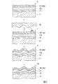
図1は、本発明の透明基板の一例を示す断面図である。
本実施形態の透明基板10は、透光性を有する基材11と、基材11上に設けられたバリア層12と、バリア層12上に設けられた緩衝層13と、緩衝層13上に設けられた反射防止層14とを具備して構成されている。
透明基板10は、詳しくは後述するが、図2に示すように、基材11と、基材11上に設けられたバリア層12と、バリア層12上に設けられた、紫外線硬化性樹脂組成物の半硬化物からなる半硬化物層13sと、半硬化物層13s上に設けられた反射防止層14とを備えた中間積層体1の、半硬化物層13sが全硬化したものである。すなわち、緩衝層13は、半硬化物層13sが全硬化したもの(半硬化物層13sの全硬化物)である。
"Transparent board"
FIG. 1 is a cross-sectional view showing an example of the transparent substrate of the present invention.
The
The
図1に示すように、透明基板10は、反射防止層14の表面に不規則な凹凸構造を有している。反射防止層14の表面に不規則な凹凸構造を有することで、防眩性を発現する。
ここで、「不規則な凹凸構造」とは、形状、寸法などが異なる複数の凹部および凸部が、不規則な配列パターン(間隔)で形成していることを意味する。
As shown in FIG. 1, the
Here, the "irregular uneven structure" means that a plurality of concave portions and convex portions having different shapes, dimensions, and the like are formed in an irregular arrangement pattern (interval).
凹凸構造の表面の算術平均粗さRaは、0.01〜1.00μmであり、0.03〜0.50μmが好ましい。算術平均粗さRaが0.01μm以上であれば、充分な防眩性を発現できる。一方、算術平均粗さRaが1.00μm以下であれば、ギラつきが起こりにくい。
また、凹凸構造の表面の算術平均高さSaは、0.01〜1.25μmが好ましく、0.03〜0.60μmがより好ましい。算術平均高さSaが0.01μm以上であれば、充分な防眩性を発現できる。一方、算術平均高さSaが1.25μm以下であれば、ギラつきが起こりにくい。
また、凹凸構造の表面の平均凹凸周期RSmは、1〜30μmであり、5〜15μmが好ましい。平均凹凸周期RSmが1μm以上であれば、充分な防眩性を発現できる。一方、平均凹凸周期RSmが30μm以下であれば、ギラつきが起こりにくい。
本発明において、算術平均粗さRa、算術平均高さSaおよび平均凹凸周期RSmは、ISO 25178によって測定される値であり、市販の表面性状測定機を利用して測定することができる。係る測定器としては、例えば形状解析レーザ顕微鏡などが挙げられる。
The arithmetic mean roughness Ra of the surface of the uneven structure is 0.01 to 1.00 μm, preferably 0.03 to 0.50 μm. When the arithmetic mean roughness Ra is 0.01 μm or more, sufficient antiglare property can be exhibited. On the other hand, when the arithmetic mean roughness Ra is 1.00 μm or less, glare is unlikely to occur.
The arithmetic mean height Sa of the surface of the uneven structure is preferably 0.01 to 1.25 μm, more preferably 0.03 to 0.60 μm. When the arithmetic mean height Sa is 0.01 μm or more, sufficient antiglare property can be exhibited. On the other hand, if the arithmetic mean height Sa is 1.25 μm or less, glare is unlikely to occur.
The average unevenness period RSm on the surface of the uneven structure is 1 to 30 μm, preferably 5 to 15 μm. When the average uneven period RSm is 1 μm or more, sufficient antiglare property can be exhibited. On the other hand, when the average unevenness period RSm is 30 μm or less, glare is unlikely to occur.
In the present invention, the arithmetic mean roughness Ra, the arithmetic mean height Sa, and the average unevenness period RSm are values measured by ISO 25178 and can be measured using a commercially available surface texture measuring machine. Examples of such a measuring instrument include a shape analysis laser microscope.
<基材>
基材11は、透光性を有するものであり、例えば、波長750〜400nmでの全光線透過率が85%以上の熱可塑性樹脂からなる。このような透光性を有する熱可塑性樹脂としては、ポリメチルメタクリレートに代表されるアクリル系樹脂、ポリカーボネート樹脂、ポリエチレンテレフタレート樹脂、ポリアリルジグリコールカーボネート樹脂、ポリスチレン樹脂等が好適である。
基材11は、反射防止層14が形成される側の面が、アクリル系樹脂、ポリカーボネート樹脂またはポリエチレンテレフタレート樹脂により形成されていることが好ましく、従って、ポリカーボネート樹脂とアクリル系樹脂との積層体も、基材11として好適に使用することができる。
<Base material>
The
The surface of the
基材11は、透光性が損なわれない限りにおいて、油溶性染料等によって着色されたものであってよい。
また、基材11の反射防止層14が形成される側の面は、基材11と隣接する層との密着性を向上させる目的で、それ自体公知のプライマーで表面処理されていてもよい。
The
Further, the surface of the
基材11の厚さは、凹凸が附形される厚さであれば特に制限されないが、一般的には適度に薄肉であることが好ましく、例えば、30〜1000μm程度の厚さであることが好ましい。
The thickness of the
<バリア層>
バリア層12は、透明基板10に耐薬品性を付与するものであり、ブレーキオイル等の薬品に透明基板10が曝されたときに、基材11が薬品によって膨潤するのを防止する役割を果たす。
<Barrier layer>
The
バリア層12は、4官能以上のウレタンアクリレートを含む。4官能以上のウレタンアクリレートは硬化により硬質の部分を形成する。よって、バリア層12を備える透明基板10は、高い耐薬品性を有するものとなる。
4官能以上のウレタンアクリレートは、多価イソシアネート化合物と複数の水酸基を有するポリオール化合物との反応物である末端イソシアネート化合物に、さらに水酸基含有(メタ)アクリレートを反応させて得られるもの(末端イソシアネート化合物と水酸基含有(メタ)アクリレートとの反応物)のうち、(メタ)アクリロイル基を4つ以上有するものである。
例えば、ペンタエリスリトールジ(メタ)アクリレートを、末端イソシアネート化合物と反応させ、イソシアネート化合物の両末端に、それぞれ2個の(メタ)アクリロイル基を導入したものは、4官能のウレタンアクリレートとして使用される。また、ペンタエリスリトールトリ(メタ)アクリレートを、両末端イソシアネート(例えばトリヘキサジエチレンジイソシアネート)と反応させることにより、分子鎖末端のそれぞれに3個の(メタ)アクリロイル基を導入したものは、6官能のウレタンアクリレートとして使用される。
The
The tetrafunctional or higher functional urethane acrylate is obtained by further reacting a terminal isocyanate compound, which is a reaction product of a polyvalent isocyanate compound and a polyol compound having a plurality of hydroxyl groups, with a hydroxyl group-containing (meth) acrylate (with a terminal isocyanate compound). Among the (reactants with hydroxyl group-containing (meth) acrylate), those having four or more (meth) acryloyl groups.
For example, pentaerythritol di (meth) acrylate is reacted with a terminal isocyanate compound, and two (meth) acryloyl groups are introduced at both ends of the isocyanate compound, which is used as a tetrafunctional urethane acrylate. In addition, pentaerythritol tri (meth) acrylate with three (meth) acryloyl groups introduced at each end of the molecular chain by reacting with both terminal isocyanates (for example, trihexadiethylene diisocyanate) is hexafunctional. Used as urethane acrylate.
4官能以上のウレタンアクリレートを構成する多価イソシアネート化合物としては、例えば、エチレンジイソシアネート、プロピレンジイソシアネート、ブチレンジイソシアネート、ペンタメチレンジイソシアネート、ヘキサメチレンジイソシアネート等の脂肪族ジイソシアネート類;イソホロンジイソシアネート、4,4’−メチレンビス(シクロヘキシルイソシアネート)、ω,ω’−ジイソシネートジメチルシクロヘキサン等の脂環族ジイソシアネート類;トリレンジイソシアネート、キシリレンジイソシアネート、α,α,α’,α’−テトラメチルキシリレンジイソシアネート等の芳香環を有する脂肪族ジイソシアネート類などが挙げられる。
これらは、1種単独で用いてもよいし、2種以上を併用してもよい。
Examples of the polyvalent isocyanate compound constituting the tetrafunctional or higher functional urethane acrylate include aliphatic diisocyanates such as ethylene diisocyanate, propylene diisocyanate, butylene diisocyanate, pentamethylene diisocyanate, and hexamethylene diisocyanate; isophorone diisocyanate and 4,4'-methylenebis. Alicyclic diisocyanates such as (cyclohexylisocyanate), ω, ω'-diisosinate dimethylcyclohexane; aromatic rings such as tolylene diisocyanate, xylylene diisocyanate, α, α, α', α'-tetramethylxylylene diisocyanate Examples thereof include aliphatic diisocyanates having.
These may be used alone or in combination of two or more.
4官能以上のウレタンアクリレートを構成するポリオール化合物としては、例えば、グリセリン、ジグリセリン、トリグリセリン、トリメチロールエタン、トリメチロールプロパン、ソルビトール、ペンタエリスリトール、ジトリメチロールプロパン、ジペンタエリスリトール、トリペンタエリスリトール、アダマンタントリオールなどが挙げられる。
これらは、1種単独で用いてもよいし、2種以上を併用してもよい。
Examples of the polyol compound constituting a tetrafunctional or higher functional urethane acrylate include glycerin, diglycerin, triglycerin, trimethylolethane, trimethylolpropane, sorbitol, pentaerythritol, ditrimethylolpropane, dipentaerythritol, tripentaerythritol, and adamantan. Triol and the like can be mentioned.
These may be used alone or in combination of two or more.
4官能以上のウレタンアクリレートを構成する水酸基含有(メタ)アクリレートとしては、例えば、ペンタエリスリトールジ(メタ)アクリレート、ペンタエリスリトールトリ(メタ)アクリレート、ジペンタエリスリトールペンタ(メタ)アクリレートなどが挙げられる。
これらは、1種単独で用いてもよいし、2種以上を併用してもよい。
Examples of the hydroxyl group-containing (meth) acrylate constituting the tetrafunctional or higher functional urethane acrylate include pentaerythritol di (meth) acrylate, pentaerythritol tri (meth) acrylate, and dipentaerythritol penta (meth) acrylate.
These may be used alone or in combination of two or more.
バリア層12の伸び率は、後述する半硬化物層13sの伸び率と同じであることが好ましい。
バリア層12の伸び率は、以下のようにして求められる。
すなわち、基材上にバリア層が形成された試験片について、基材のTg付近まで加温した後、L字曲げ雄雌型の間に、基材面が凹部側となるように挟み、雄雌型を押し合い冷却する。冷却後、曲げた凸面をマイクロスコープで観察し、クラックの有無を確認する。曲げ半径(曲げR)を変えて同様の操作を行い、クラックが発生しなかったときの曲げRまでの伸び率を算出する。
The elongation rate of the
The elongation rate of the
That is, the test piece having the barrier layer formed on the base material is heated to the vicinity of Tg of the base material, and then sandwiched between the L-shaped bent male and female molds so that the base material surface is on the concave side. Press the female molds together to cool. After cooling, observe the bent convex surface with a microscope to check for cracks. The same operation is performed by changing the bending radius (bending R), and the elongation rate up to the bending R when no crack occurs is calculated.
バリア層12の厚さは、50〜200nmが好ましく、60〜150nmがより好ましい。バリア層12の厚さが50nm以上であれば、充分な硬度と耐薬品性が得られる。バリア層による耐薬品性等の効果は、バリア層が厚くなるほど得られやすくなる傾向にあるが、200nmを超えると頭打ちとなる。耐薬品性等の効果と、透明基板10全体の厚さとのバランスの観点から、バリア層12の厚さ200nm以下が好ましい。
The thickness of the
<緩衝層>
緩衝層13は、後述する半硬化物層13sが全硬化したもの(半硬化物層13sの全硬化物)である。
<Cushioning layer>
The
(半硬化物層)
半硬化物層13sは、反射防止層14の表面を凹凸形状に加工する際の緩衝材の役割を果たす。詳しくは後述するが、反射防止層14の表面の凹凸形状は、転写面に凹凸構造を有する転写モールドを用いて中間積層体1の反射防止層14の表面に凹凸を附形することにより形成される。中間積層体1が半硬化物層13sを備えることで、反射防止層14の表面を凹凸形状に加工しても、転写処理時に反射防止層14に加わる外力を半硬化物層13sが吸収するので、反射防止層14が損傷するのを防止でき、反射防止層14の本来の機能(反射防止性)を良好に維持できる。
(Semi-cured product layer)
The
半硬化物層13sは、紫外線硬化性樹脂組成物の半硬化物からなる。
なお、本発明において「半硬化」とは、紫外線硬化性樹脂組成物が完全に硬化する前の状態であり、さらに硬化反応を進行させることが可能な状態を指す。具体的には、紫外線硬化性樹脂組成物の硬化反応が60〜90%完了した状態を指す。
The
In the present invention, "semi-curing" refers to a state before the ultraviolet curable resin composition is completely cured, and a state in which the curing reaction can be further advanced. Specifically, it refers to a state in which the curing reaction of the ultraviolet curable resin composition is 60 to 90% complete.
半硬化物層13sのヤング率は、0.1〜2.5GPaであり、0.3〜2.0GPaが好ましく、0.4〜1.5GPaがより好ましい。半硬化物層13sのヤング率が0.1GPa以上であれば、半硬化物層13s上への反射防止層の形成が可能であり、反射防止性を保持できる。一方、半硬化物層13sのヤング率が2.5GPa以下であれば、反射防止層14の表面を凹凸形状に加工する際(転写処理時)の圧力を充分に吸収できる。
本発明において、ヤング率は、JIS K 7171に準拠して温度23℃、速度1mm/minの条件で曲げ試験を行い、歪み−応力曲線を描いたときに、該歪み−応力曲線の直線部分の傾きにより表される値である。
The Young's modulus of the
In the present invention, Young's modulus is determined by performing a bending test under the conditions of a temperature of 23 ° C. and a speed of 1 mm / min in accordance with JIS K 7171, and when a strain-stress curve is drawn, the linear portion of the strain-stress curve is drawn. It is a value represented by the slope.
半硬化物層13sの伸び率は、105〜200%が好ましく、108〜180%がより好ましく、115〜160%がさらに好ましい。半硬化物層13sの伸び率が105%以上であれば、反射防止層14の表面を凹凸形状に加工する際(転写処理時)の圧力をより吸収できる。一方、半硬化物層13sの伸び率が200%以下であれば、半硬化物層13s上への反射防止層の形成が可能であり、反射防止性を保持できる。
半硬化物層13sの伸び率は、以下のようにして求められる。
すなわち、基材上に半硬化物層が形成された試験片について、基材のTg付近まで加温した後、L字曲げ雄雌型の間に、基材面が凹部側となるように挟み、雄雌型を押し合い冷却する。冷却後、曲げた凸面をマイクロスコープで観察し、クラックの有無を確認する。曲げ半径(曲げR)を変えて同様の操作を行い、クラックが発生しなかったときの曲げRまでの伸び率を算出する。
The elongation rate of the
The elongation rate of the
That is, after heating the test piece in which the semi-cured product layer is formed on the base material to the vicinity of Tg of the base material, the test piece is sandwiched between the L-shaped bent male and female molds so that the base material surface is on the concave side. , Press and cool the male and female molds. After cooling, observe the bent convex surface with a microscope to check for cracks. The same operation is performed by changing the bending radius (bending R), and the elongation rate up to the bending R when no crack occurs is calculated.
紫外線硬化性樹脂組成物は、3官能以下のウレタンアクリレート、シランカップリング剤および金属キレート化合物を含むことが好ましい。
また、紫外線硬化性樹脂組成物は、シリカ粒子や4官能以上のウレタンアクリレートをさらに含むことがより好ましい。
The UV curable resin composition preferably contains a trifunctional or less functional urethane acrylate, a silane coupling agent, and a metal chelate compound.
Further, it is more preferable that the ultraviolet curable resin composition further contains silica particles and urethane acrylate having four or more functionalities.
3官能以下のウレタンアクリレートは、多価イソシアネート化合物と複数の水酸基を有するポリオール化合物との反応物である末端イソシアネート化合物に、さらに水酸基含有(メタ)アクリレートを反応させて得られるもの(末端イソシアネート化合物と水酸基含有(メタ)アクリレートとの反応物)のうち、(メタ)アクリロイル基を3つ以下有するものである。(メタ)アクリロイル基を1つ有するウレタンアクリレートは1官能(単官能)であり、(メタ)アクリロイル基を2つ有するウレタンアクリレートは2官能であり、(メタ)アクリロイル基を3つ有するウレタンアクリレートは3官能である。
例えば、ペンタエリスリトールモノ(メタ)アクリレートを、末端イソシアネート化合物と反応させ、イソシアネート化合物の両末端に、それぞれ1個の(メタ)アクリロイル基を導入したものは、2官能のウレタンアクリレートとして使用される。また、ペンタエリスリトールモノ(メタ)アクリレートとペンタエリスリトールジ(メタ)アクリレートとを、末端イソシアネート化合物と反応させ、イソシアネート化合物の一方の末端に1個の(メタ)アクリロイル基を導入し、他方の末端に2個の(メタ)アクリロイル基を導入したものは、3官能のウレタンアクリレートとして使用される。
The trifunctional or lower urethane acrylate is obtained by further reacting a terminal isocyanate compound, which is a reaction product of a polyvalent isocyanate compound and a polyol compound having a plurality of hydroxyl groups, with a hydroxyl group-containing (meth) acrylate (with a terminal isocyanate compound). Among the (reactants with hydroxyl group-containing (meth) acrylate), those having three or less (meth) acryloyl groups. Urethane acrylates with one (meth) acryloyl group are monofunctional (monofunctional), urethane acrylates with two (meth) acryloyl groups are bifunctional, and urethane acrylates with three (meth) acryloyl groups are It is trifunctional.
For example, pentaerythritol mono (meth) acrylate is reacted with a terminal isocyanate compound, and one (meth) acryloyl group is introduced at both ends of the isocyanate compound, which is used as a bifunctional urethane acrylate. Further, pentaerythritol mono (meth) acrylate and pentaerythritol di (meth) acrylate are reacted with a terminal isocyanate compound to introduce one (meth) acryloyl group at one end of the isocyanate compound and at the other end. Those introduced with two (meth) acryloyl groups are used as trifunctional urethane acrylates.
3官能以下のウレタンアクリレートを構成する多価イソシアネート化合物およびポリオール化合物としては、4官能以上のウレタンアクリレートの説明において先に例示した多価イソシアネート化合物およびポリオール化合物が挙げられる。 Examples of the polyisocyanate compound and the polyol compound constituting the trifunctional or lower functional urethane acrylate include the polyvalent isocyanate compound and the polyol compound exemplified above in the description of the tetrafunctional or higher functional urethane acrylate.
3官能以下のウレタンアクリレートを構成する水酸基含有(メタ)アクリレートとしては、例えば、ペンタエリスリトールモノ(メタ)アクリレート、ペンタエリスリトールジ(メタ)アクリレート、フェニルグリシジルエーテル(メタ)アクリレートなどが挙げられる。
これらは、1種単独で用いてもよいし、2種以上を併用してもよい。
Examples of the hydroxyl group-containing (meth) acrylate constituting the trifunctional or lower urethane acrylate include pentaerythritol mono (meth) acrylate, pentaerythritol di (meth) acrylate, and phenylglycidyl ether (meth) acrylate.
These may be used alone or in combination of two or more.
4官能以上のウレタンアクリレートとしては、バリア層12の説明において先に例示した4官能以上のウレタンアクリレートが挙げられる。
Examples of the tetrafunctional or higher functional urethane acrylate include the tetrafunctional or higher functional urethane acrylate exemplified above in the description of the
3官能以下のウレタンアクリレートは硬化により比較的柔軟性に富んだ部分を形成し、4官能以上のウレタンアクリレートは硬化により硬質の部分を形成するものであり、両者を併用することにより、適度に緻密で硬度の緩衝層13を形成することができる。
紫外線硬化性樹脂組成物に含まれる全てのウレタンアクリレートの総質量に対し、3官能以下のウレタンアクリレートの含有量は5質量%以上が好ましく、4官能以上のウレタンアクリレートの含有量は95質量%以下が好ましい。3官能以下のウレタンアクリレートの含有量が5質量%以上であれば、半硬化物層13sと基材11との密着性が高まり、半硬化物層13sの基材11に対する追随性が損なわれにくくなる。その結果、透明基板10を加圧附形する際に割れ等が生じにくくなる。また、紫外線硬化性樹脂組成物がシリカ粒子を含有する場合、シリカ粒子の脱落を抑制できる。一方、4官能以上のウレタンアクリレートの含有量が95質量%以下であれば、緩衝層13の硬度を良好に維持できる。
3官能以下のウレタンアクリレートの含有量は、5〜100質量%が好ましく、12〜90質量%がより好ましく、4官能以上のウレタンアクリレートの含有量は0〜95質量%が好ましく、10〜88質量%がより好ましい。
Urethane acrylates with trifunctionality or less form a relatively flexible portion by curing, and urethane acrylates with four or more functionalities form a hard portion by curing. By using both in combination, they are appropriately dense. Can form a
The content of trifunctional or lower urethane acrylate is preferably 5% by mass or more, and the content of tetrafunctional or higher functional urethane acrylate is 95% by mass or less with respect to the total mass of all urethane acrylates contained in the ultraviolet curable resin composition. Is preferable. When the content of the urethane acrylate having trifunctionality or less is 5% by mass or more, the adhesion between the
The content of the urethane acrylate having trifunctionality or less is preferably 5 to 100% by mass, more preferably 12 to 90% by mass, and the content of urethane acrylate having four or more functionalities is preferably 0 to 95% by mass, and 10 to 88% by mass. % Is more preferable.
シランカップリング剤は、基材11や反射防止層14との密着性を高める成分である。また、紫外線硬化性樹脂組成物がシリカ粒子を含有する場合、シリカ粒子の脱落を抑制し、安定に分散させて保持させる成分でもある。
シランカップリング剤としては、下記一般式(1)で表される化合物が挙げられる。
R1 n−Si(OR2)4−n ・・・(1)
式(1)中、R1はアルキル基またはアルケニル基であり、R2はアルキル基、アルコキシアルキル基、アシルオキシ基またはハロゲン原子であり、nは1または2の数である。
The silane coupling agent is a component that enhances the adhesion to the
Examples of the silane coupling agent include compounds represented by the following general formula (1).
R 1 n −Si (OR 2 ) 4-n ... (1)
In formula (1), R 1 is an alkyl group or an alkenyl group, R 2 is an alkyl group, an alkoxyalkyl group, an acyloxy group or a halogen atom, and n is a number of 1 or 2.
R1としては、メチル基、エチル基、プロピル基等のアルキル基、ビニル基等のアルケニル基が挙げられ、このアルキル基は、塩素等のハロゲン原子、メルカプト基、アミノ基、(メタ)アクリロイル基、オキシラン環含有基等の官能基で置換されていてもよい。
R2は、アルキル基、アルコキシアルキル基、アシルオキシ基またはハロゲン原子であり、ケイ素原子に結合しているOR2は加水分解性の基となっている。
Examples of R 1 include an alkyl group such as a methyl group, an ethyl group and a propyl group, and an alkenyl group such as a vinyl group. The alkyl group includes a halogen atom such as chlorine, a mercapto group, an amino group and a (meth) acryloyl group. , Oxylan ring-containing group or the like may be substituted with a functional group.
R 2 is an alkyl group, an alkoxyalkyl group, an acyloxy group or a halogen atom, and OR 2 bonded to the silicon atom is a hydrolyzable group.
式(1)で表される化合物としては、例えば、ビニルトリクロロシラン、ビニルトリス(β−メトキシエトキシ)シラン、ビニルトリエトキシシラン、ビニルトリメトキシシラン、ビニルトリアセトキシシラン、γ−(メタ)アクリロキシプロピルトリメトキシシラン、γ−グリシドキシプロピルトリメトキシシラン、β−(3,4−エポキシシクロヘキシル)エチルトリメトキシシラン、γ−グリシドキシプロピルメチルジエトキシシラン、γ−アミノプロピルトリエトキシシラン、γ−アミノプロピルメチルジメトキシシラン、N−(β−アミノエチル)−γ−アミノプロピルトリメトキシシラン、γ−アニリノプロピルトリメトキシシラン、γ−(N−スチリルメチル−β−アミノエチルアミノ)プロピルトリメトキシシラン塩酸塩、γ−クロロプロピルトリメトキシシラン、γ−メルカプトプロピルトリメトキシシラン、メチルトリメトキシシラン、メチルトリクロロシラン、ジメチルジクロロシランなどが挙げられる。
これらは、1種単独で用いてもよいし、2種以上を併用してもよい。
Examples of the compound represented by the formula (1) include vinyltrichlorosilane, vinyltris (β-methoxyethoxy) silane, vinyltriethoxysilane, vinyltrimethoxysilane, vinyltriacetoxysilane, and γ- (meth) acryloxipropyl. Trimethoxysilane, γ-glycidoxypropyltrimethoxysilane, β- (3,4-epoxycyclohexyl) ethyltrimethoxysilane, γ-glycidoxypropylmethyldiethoxysilane, γ-aminopropyltriethoxysilane, γ- Aminopropylmethyldimethoxysilane, N- (β-aminoethyl) -γ-aminopropyltrimethoxysilane, γ-anilinopropyltrimethoxysilane, γ- (N-styrylmethyl-β-aminoethylamino) propyltrimethoxysilane Examples thereof include hydrochloride, γ-chloropropyltrimethoxysilane, γ-mercaptopropyltrimethoxysilane, methyltrimethoxysilane, methyltrichlorosilane, and dimethyldichlorosilane.
These may be used alone or in combination of two or more.
このようなシランカップリング剤は、加水分解と同時に重縮合し、Si−O−Si結合によりネットワーク状に連なった重合物を形成する。従って、このようなシランカップリング剤の使用により、緩衝層13を緻密なものとすることもできる。
なお、半硬化物層13sおよび緩衝層13中において、シランカップリング剤の少なくとも一部は、加水分解物として存在する。
Such a silane coupling agent is polycondensed at the same time as hydrolysis to form a polymer connected in a network by a Si—O—Si bond. Therefore, by using such a silane coupling agent, the
In the
シランカップリング剤の含有量は、紫外線硬化性樹脂組成物に含まれる全てのウレタンアクリレート100質量部に対して、1〜30質量部が好ましく、10〜15質量部がより好ましい。シランカップリング剤の含有量が1質量部以上であれば、基材11や反射防止層14との密着性が高まり、半硬化物層13sや緩衝層13が剥がれるのを抑制できる。一方、シランカップリング剤の含有量が30質量部以下であれば、半硬化物層13sの基本的性能(反射防止層14に加わる外力の吸収)を充分に発揮できる。
The content of the silane coupling agent is preferably 1 to 30 parts by mass, more preferably 10 to 15 parts by mass, based on 100 parts by mass of all urethane acrylates contained in the ultraviolet curable resin composition. When the content of the silane coupling agent is 1 part by mass or more, the adhesion to the
金属キレート化合物は、半硬化物層13s中に架橋構造を導入し、半硬化物層13sや緩衝層13をより緻密なものとするために使用される。上述した3官能以下のウレタンアクリレートは柔軟性を付与するものの、緻密性を低下させやすい。金属キレート化合物は、半硬化物層13sの柔軟性を損なうことなく緻密性の低下を補うものである。換言すると、金属キレート化合物は膜の緻密性に影響される硬度等の機械的特性を調整するために使用されるものである。特に、後述する反射防止層14も金属キレート化合物を含んでいれば、半硬化物層13sや緩衝層13と反射防止層14との密着性がより高められ、透明基板10を加圧附形する際の割れ等を有効に防止することができる。
The metal chelate compound is used to introduce a crosslinked structure into the
金属キレート化合物としては、二座配位子を含むチタン、ジルコニウム、アルミニウム、スズ、ニオブ、タンタル、鉛の化合物が好適である。
二座配位子とは、配位座数が2、すなわち金属に配位しうる原子数が2であるようなキレート剤であり、一般にO、N、S原子によって5〜7員環を形成して、キレート化合物を形成する。これらの二座配位子の例として、アセチルアセトナト、エチルアセトアセタト、ジエチルマロナト、ジベンゾイルメタナト、サリチラト、グリコラト、カテコラト、サリチルアルデヒダト、オキシアセトフェノナト、ビフェノラト、ピロメコナト、オキシナフトキノナト、オキシアントラキノナト、トロポロナト、ビノキチラト、グリシナト、アラニナト、アントロニナト、ピコリナト、アミノフェノラト、エタノールアミナト、メルカプトエチルアミナト、8−オキシキノリナト、サリチルアルジミナト、ベンゾインオキシマト、サリチルアルドキシマト、オキシアゾベンゼナト、フェニルアゾナフトラト、β−ニトロソ−α−ナフトラト、ジアゾアミノベンゼナト、ビウレタト、ジフェニルカルバゾナト、ジフェニルチオカルバゾナト、ビグアニダト、ジメチルグリオキシマトなどが挙げられる。
As the metal chelate compound, a compound of titanium, zirconium, aluminum, tin, niobium, tantalum, or lead containing a bidentate ligand is suitable.
A bidentate ligand is a chelating agent having 2 coordination loci, that is, 2 atoms that can coordinate with a metal, and generally forms a 5- to 7-membered ring with O, N, and S atoms. To form a chelate compound. Examples of these bidentate ligands are acetylacetonato, ethylacetacetate, diethylmalonato, dibenzoylmethanato, salicilato, glycolat, catecholato, salicylaldehidat, oxyacetophenonato, biphenolato, pyromeconato, oxynaphthokino. Nato, Oxyanthraquinonato, Tropolonato, Binokichirat, Glycinato, Alaninato, Antroninato, Picolinato, Aminophenorato, Ethanol Aminato, Mercaptoethylaminato, 8-Oxyquinolinato, Salicylargiminato, Benzoin Oxymato, Salicylaldoxymato Examples thereof include azobenzenato, phenylazonaftrat, β-nitroso-α-naphtholto, diazoaminobenzenato, biuretato, diphenylcarbazonat, diphenylthiocarbazonato, biguanidato, dimethylglioxymate and the like.
金属キレート化合物としては、下記一般式(2)で表される化合物が好ましい。
M1(Li)k(X)m−k ・・・(2)
式(2)中、M1はチタン、ジルコニウム、アルミニウム、スズ、ニオブ、タンタルまたは鉛であり、Liは二座配位子であり、Xは1価の基であり、mはM1の原子価であり、kはM1の原子価を超えない範囲で1以上の数である。
As the metal chelate compound, a compound represented by the following general formula (2) is preferable.
M 1 (Li) k (X) m-k ... (2)
In formula (2), M 1 is titanium, zirconium, aluminum, tin, niobium, tantalum or lead, Li is a bidentate ligand, X is a monovalent group and m is an atom of M 1 . It is a valence, and k is a number of 1 or more within a range not exceeding the valence of M 1 .
M1としては、チタン、ジルコニウム、アルミニウムが好ましい。
Xとしては、加水分解可能な基が好ましく、その中でも特にアルコキシ基が好ましい。
As M 1 , titanium, zirconium, and aluminum are preferable.
As X, a hydrolyzable group is preferable, and among them, an alkoxy group is particularly preferable.
式(2)で表される金属キレート化合物としては、例えば、Tiキレート化合物、Zrキレート化合物、Alキレート化合物などが挙げられる。
Tiキレート化合物の具体例としては、トリエトキシ・モノ(アセチルアセトナト)チタン、トリ−n−プロポキシ・モノ(アセチルアセトナト)チタン、トリ−i−プロポキシ・モノ(アセチルアセトナト)チタン、トリ−n−ブトキシ・モノ(アセチルアセトナト)チタン、トリ−sec−ブトキシ・モノ(アセチルアセトナト)チタン、トリ−t−ブトキシ・モノ(アセチルアセトナト)チタン、ジエトキシ・ビス(アセチルアセトナト)チタン、ジ−n−プロポキシ・ビス(アセチルアセトナト)チタン、ジ−i−プロポキシ・ビス(アセチルアセトナト)チタン、ジ−n−ブトキシ・ビス(アセチルアセトナト)チタン、ジ−sec−ブトキシ・ビス(アセチルアセトナト)チタン、ジ−t−ブトキシ・ビス(アセチルアセトナト)チタン、モノエトキシ・トリス(アセチルアセトナト)チタン、モノ−n−プロポキシ・トリス(アセチルアセトナト)チタン、モノ−i−プロポキシ・トリス(アセチルアセトナト)チタン、モノ−n−ブトキシ・トリス(アセチルアセトナト)チタン、モノ−sec−ブトキシ・トリス(アセチルアセトナト)チタン、モノ−t−ブトキシ・トリス(アセチルアセトナト)チタン、テトラキス(アセチルアセトナト)チタン、トリエトキシ・モノ(エチルアセトアセタト)チタン、トリ−n−プロポキシ・モノ(エチルアセトアセタト)チタン、トリ−i−プロポキシ・モノ(エチルアセトアセタト)チタン、トリ−n−ブトキシ・モノ(エチルアセトアセタト)チタン、トリ−sec−ブトキシ・モノ(エチルアセトアセタト)チタン、トリ−t−ブトキシ・モノ(エチルアセトアセタト)チタン、ジエトキシ・ビス(エチルアセトアセタト)チタン、ジ−n−プロポキシ・ビス(エチルアセトアセタト)チタン、ジ−i−プロポキシ・ビス(エチルアセトアセタト)チタン、ジ−n−ブトキシ・ビス(エチルアセトアセタト)チタン、ジ−sec−ブトキシ・ビス(エチルアセトアセタト)チタン、ジ−t−ブトキシ・ビス(エチルアセトアセタト)チタン、モノエトキシ・トリス(エチルアセトアセタト)チタン、モノ−n−プロポキシ・トリス(エチルアセトアセタト)チタン、モノ−i−プロポキシ・トリス(エチルアセトアセタト)チタン、モノ−n−ブトキシ・トリス(エチルアセトアセタト)チタン、モノ−sec−ブトキシ・トリス(エチルアセトアセタト)チタン、モノ−t−ブトキシ・トリス(エチルアセトアセタト)チタン、テトラキス(エチルアセトアセタト)チタン、モノ(アセチルアセトナト)トリス(エチルアセトアセタト)チタン、ビス(アセチルアセトナト)ビス(エチルアセトアセタト)チタン、トリス(アセチルアセトナト)モノ(エチルアセトアセタト)チタンなどが挙げられる。
これらは、1種単独で用いてもよいし、2種以上を併用してもよい。
Examples of the metal chelate compound represented by the formula (2) include Ti chelate compounds, Zr chelate compounds, and Al chelate compounds.
Specific examples of the Ti chelate compound include triethoxy mono (acetylacetonato) titanium, tri-n-propoxymono (acetylacetonato) titanium, tri-i-propoxymono (acetylacetonato) titanium, and tri-n. -Butoxy mono (acetylacetonato) titanium, tri-sec-butoxy mono (acetylacetonato) titanium, trit-butoxy mono (acetylacetonato) titanium, diethoxy bis (acetylacetonato) titanium, di -N-propoxybis (acetylacetonato) titanium, di-i-propoxybis (acetylacetonato) titanium, di-n-butoxybis (acetylacetonato) titanium, di-sec-butoxybis (acetyl) Acetonato) Titanium, Di-t-butoxy-bis (acetylacetonato) titanium, Monoethoxytris (acetylacetonato) titanium, Mono-n-propoxytris (acetylacetonato) titanium, Mono-i-propoxy Tris (acetylacetonato) titanium, mono-n-butoxytris (acetylacetonato) titanium, mono-sec-butoxytris (acetylacetonato) titanium, mono-t-butoxytris (acetylacetonato) titanium, Tetrax (acetylacetonato) titanium, triethoxy mono (ethylacetacetate) titanium, tri-n-propoxymono (ethylacetacetate) titanium, tri-i-propoxymono (ethylacetacetate) titanium, tri -N-Butoxy mono (ethylacetacetate) titanium, tri-sec-butoxymono (ethylacetacetate) titanium, trit-butoxymono (ethylacetacetate) titanium, diethoxybis (ethylacetate) Acetato) Titanium, Di-n-propoxybis (ethylacetacetato) titanium, Di-i-propoxybis (ethylacetacetato) titanium, Di-n-butoxybis (ethylacetacetato) titanium, Di-sec-butoxy bis (ethylacetacetate) titanium, dit-butoxy bis (ethylacetacetate) titanium, monoethoxytris (ethylacetacetate) titanium, mono-n-propoxytris ( Ethylacetacetate) Titanium, Mono-i-propoxytris (Ethylacetacetato) Titanium, Mono-n-Butoxytris (Ethylacetacetato) Titanium, Mono-sec-Butoxytris (Ethylacetacetato) ) Titanium, Mono-t-Butoxy Tris (Ethylacet Acetato) Titanium, Tetrax (Ethylacet Acetato) Titanium, Mono (Acetylacetonato) Tris (Ethylacet Acetato) Titanium, Bis (Acetylacetonato) Bis Examples thereof include (ethylacetacetate) titanium and tris (acetylacetonato) mono (ethylacetacetate) titanium.
These may be used alone or in combination of two or more.
Zrキレート化合物の具体例としては、トリエトキシ・モノ(アセチルアセトナト)ジルコニウム、トリ−n−プロポキシ・モノ(アセチルアセトナト)ジルコニウム、トリ−i−プロポキシ・モノ(アセチルアセトナト)ジルコニウム、トリ−n−ブトキシ・モノ(アセチルアセトナト)ジルコニウム、トリ−sec−ブトキシ・モノ(アセチルアセトナト)ジルコニウム、トリ−t−ブトキシ・モノ(アセチルアセトナト)ジルコニウム、ジエトキシ・ビス(アセチルアセトナト)ジルコニウム、ジ−n−プロポキシ・ビス(アセチルアセトナト)ジルコニウム、ジ−i−プロポキシ・ビス(アセチルアセトナト)ジルコニウム、ジ−n−ブトキシ・ビス(アセチルアセトナト)ジルコニウム、ジ−sec−ブトキシ・ビス(アセチルアセトナト)ジルコニウム、ジ−t−ブトキシ・ビス(アセチルアセトナト)ジルコニウム、モノエトキシ・トリス(アセチルアセトナト)ジルコニウム、モノ−n−プロポキシ・トリス(アセチルアセトナト)ジルコニウム、モノ−i−プロポキシ・トリス(アセチルアセトナト)ジルコニウム、モノ−n−ブトキシ・トリス(アセチルアセトナト)ジルコニウム、モノ−sec−ブトキシ・トリス(アセチルアセトナト)ジルコニウム、モノ−t−ブトキシ・トリス(アセチルアセトナト)ジルコニウム、テトラキス(アセチルアセトナト)ジルコニウム、トリエトキシ・モノ(エチルアセトアセタト)ジルコニウム、トリ−n−プロポキシ・モノ(エチルアセトアセタト)ジルコニウム、トリ−i−プロポキシ・モノ(エチルアセトアセタト)ジルコニウム、トリ−n−ブトキシ・モノ(エチルアセトアセタト)ジルコニウム、トリ−sec−ブトキシ・モノ(エチルアセトアセタト)ジルコニウム、トリ−t−ブトキシ・モノ(エチルアセトアセタト)ジルコニウム、ジエトキシ・ビス(エチルアセトアセタト)ジルコニウム、ジ−n−プロポキシ・ビス(エチルアセトアセタト)ジルコニウム、ジ−i−プロポキシ・ビス(エチルアセトアセタト)ジルコニウム、ジ−n−ブトキシ・ビス(エチルアセトアセタト)ジルコニウム、ジ−sec−ブトキシ・ビス(エチルアセトアセタト)ジルコニウム、ジ−t−ブトキシ・ビス(エチルアセトアセタト)ジルコニウム、モノエトキシ・トリス(エチルアセトアセタト)ジルコニウム、モノ−n−プロポキシ・トリス(エチルアセトアセタト)ジルコニウム、モノ−i−プロポキシ・トリス(エチルアセトアセタト)ジルコニウム、モノ−n−ブトキシ・トリス(エチルアセトアセタト)ジルコニウム、モノ−sec−ブトキシ・トリス(エチルアセトアセタト)ジルコニウム、モノ−t−ブトキシ・トリス(エチルアセトアセタト)ジルコニウム、テトラキス(エチルアセトアセタト)ジルコニウム、モノ(アセチルアセトナト)トリス(エチルアセトアセタト)ジルコニウム、ビス(アセチルアセトナト)ビス(エチルアセトアセタト)ジルコニウム、トリス(アセチルアセトナト)モノ(エチルアセトアセタト)ジルコニウムなどが挙げられる。
これらは、1種単独で用いてもよいし、2種以上を併用してもよい。
Specific examples of the Zr chelate compound include triethoxy mono (acetylacetonato) zirconium, tri-n-propoxymono (acetylacetonato) zirconium, tri-i-propoxymono (acetylacetonato) zirconium, and tri-n. -Butoxy mono (acetylacetonato) zirconium, tri-sec-butoxy mono (acetylacetonato) zirconium, trit-butoxy mono (acetylacetonato) zirconium, diethoxybis (acetylacetonato) zirconium, di -N-propoxybis (acetylacetonato) zirconium, di-i-propoxybis (acetylacetonato) zirconium, di-n-butoxybis (acetylacetonato) zirconium, di-sec-butoxybis (acetyl) Acetonato) zirconium, dit-butoxy bis (acetylacetonato) zirconium, monoethoxy tris (acetylacetonato) zirconium, mono-n-propoxytris (acetylacetonato) zirconium, mono-i-propoxy Tris (acetylacetonato) zirconium, mono-n-butoxytris (acetylacetonato) zirconium, mono-sec-butoxytris (acetylacetonato) zirconium, mono-t-butoxytris (acetylacetonato) zirconium, Tetrax (acetylacetonato) zirconium, triethoxy mono (ethylacetacetate) zirconium, tri-n-propoxymono (ethylacetacetate) zirconium, tri-i-propoxymono (ethylacetacetate) zirconium, tri -N-Butoxy mono (ethylacetacetate) zirconium, tri-sec-butoxymono (ethylacetacetate) zirconium, trit-butoxymono (ethylacetacetate) zirconium, diethoxybis (ethylacetate) Acetato) zirconium, di-n-propoxybis (ethylacetacetate) zirconium, di-i-propoxybis (ethylacetacetate) zirconium, di-n-butoxybis (ethylacetacetate) zirconium, Di-sec-butoxy bis (ethylacetacetate) zirconium, dit-butoxybis (ethylacetacetate) zirconium, monoethoxytris (ethylacetacetate) zirconium, mono-n-propoxytris ( Ethyla Seto acetato) zirconium, mono-i-propoxytris (ethylacetacetato) zirconium, mono-n-butoxy tris (ethylacetacetato) zirconium, mono-sec-butoxy tris (ethylacetacetato) zirconium, mono -T- Butoxy-tris (ethylacetacetate) zirconium, tetrakis (ethylacetacetate) zirconium, mono (acetylacetonato) tris (ethylacetacetate) zirconium, bis (acetylacetonato) bis (ethylacetacetate) ) Zirconium, tris (acetylacetonato) mono (ethylacetoacetate) zirconium and the like.
These may be used alone or in combination of two or more.
Alキレート化合物の具体例としては、ジエトキシ・モノ(アセチルアセトナト)アルミニウム、モノエトキシ・ビス(アセチルアセトナト)アルミニウム、ジ−i−プロポキシ・モノ(アセチルアセトナト)アルミニウム、モノ−i−プロポキシ・ビス(アセチルアセトナト)アルミニウム、モノ−i−プロポキシ・ビス(エチルアセトアセタト)アルミニウム、モノエトキシ・ビス(エチルアセトアセタト)アルミニウム、ジエトキシ・モノ(エチルアセトアセタト)アルミニウム、ジ−i−プロポキシ・モノ(エチルアセトアセタト)アルミニウムなどが挙げられる。
これらは、1種単独で用いてもよいし、2種以上を併用してもよい。
Specific examples of the Al chelate compound include diethoxy mono (acetylacetonato) aluminum, monoethoxybis (acetylacetonato) aluminum, di-i-propoxy mono (acetylacetonato) aluminum, and mono-i-propoxy. Bis (acetylacetonato) aluminum, mono-i-propoxybis (ethylacetacetate) aluminum, monoethoxybis (ethylacetacetate) aluminum, diethoxymono (ethylacetacetato) aluminum, di-i- Propoxy mono (ethylacetoacetate) aluminum and the like can be mentioned.
These may be used alone or in combination of two or more.
金属キレート化合物の含有量は、紫外線硬化性樹脂組成物に含まれる全てのウレタンアクリレート100質量部に対して、0.1〜3.0質量部が好ましく、0.5〜1.5質量部がより好ましい。金属キレート化合物の含有量が上記範囲内であれば、反射防止層14との密着性が向上する。
The content of the metal chelate compound is preferably 0.1 to 3.0 parts by mass, preferably 0.5 to 1.5 parts by mass, based on 100 parts by mass of all urethane acrylates contained in the ultraviolet curable resin composition. More preferred. When the content of the metal chelate compound is within the above range, the adhesion to the
シリカ粒子は、反射防止層14との密着性を高めるとともに、透明基板10を加圧附形する際の緩衝層13や反射防止層14の割れ等を効果的に抑制する成分である。
紫外線硬化性樹脂組成物に含まれるシリカ粒子としては、中実のコロイダルシリカ(中実シリカゾル)を用いることができる。ここで、「中実」とは、密度が1.9g/cm3以上を意味する。
The silica particles are components that enhance the adhesion to the
As the silica particles contained in the ultraviolet curable resin composition, solid colloidal silica (solid silica sol) can be used. Here, "solid" means a density of 1.9 g / cm 3 or more.
中実シリカゾルの平均粒子径は5〜500nmが好ましい。中実シリカゾルの平均粒子径が上記範囲内であれば、半硬化物層13sの全体にわたって、硬度等の特性を均一に付与できる。
中実シリカゾルの屈折率は、1.44〜1.50が好ましい。中実シリカゾルの屈折率が上記範囲内であれば、半硬化物層13sの全体にわたって、硬度等の特性を均一に付与できる。
The average particle size of the solid silica sol is preferably 5 to 500 nm. When the average particle size of the solid silica sol is within the above range, characteristics such as hardness can be uniformly imparted over the entire
The refractive index of the solid silica sol is preferably 1.44 to 1.50. When the refractive index of the solid silica sol is within the above range, characteristics such as hardness can be uniformly imparted over the entire
中実シリカゾルは、例えば中実シリカ粒子をイソプロパノールやメチルイソブチルケトンなどの有機溶媒に分散させたゾルの形で市販されている。 The solid silica sol is commercially available, for example, in the form of a sol in which solid silica particles are dispersed in an organic solvent such as isopropanol or methyl isobutyl ketone.
シリカ粒子の含有量は、紫外線硬化性樹脂組成物に含まれる全てのウレタンアクリレート100質量部に対して、80質量部以下が好ましく、10〜60質量部がより好ましく、20〜50質量部がさらに好ましい。シリカ粒子の含有量が上記範囲内であれば、半硬化物層13sの基本特性を維持しつつ、反射防止層14との密着性を高め、透明基板10を加圧附形する際の割れ等を有効に防止することができる。
The content of the silica particles is preferably 80 parts by mass or less, more preferably 10 to 60 parts by mass, and further preferably 20 to 50 parts by mass with respect to 100 parts by mass of all urethane acrylates contained in the ultraviolet curable resin composition. preferable. When the content of the silica particles is within the above range, the adhesion with the
半硬化物層13sの全硬化後の厚さ、すなわち緩衝層13の厚さは1.0〜10.0μmであり、1.2〜8.5μmが好ましく、1.5〜5.0μmがより好ましく、1.5〜3.0μmがさらに好ましい。半硬化物層13sの全硬化後の厚さが1.0μm以上であれば、半硬化物層13sの基本的性能(反射防止層14に加わる外力の吸収)を充分に発揮できる。一方、半硬化物層13sの全硬化後の厚さが10.0μm以下であれば、基材11との物性差(例えば柔軟性や伸び)が大きくなるのを抑制でき、転写により凹凸を附形する際の割れ等を有効に防止することができる。また、転写モールドの転写面の凹凸構造を充分に転写できる(すなわち、転写率が高い)。
The thickness of the
<反射防止層>
反射防止層14は、屈折率が1.47以下であり、厚さが50〜200nmである低屈折率層14aを最表層に備える。図1、2に示す反射防止層14は単層構造であり、低屈折率層14aのみで構成されている。
<Anti-reflective layer>
The
低屈折率層14aは、シリカ粒子と、シランカップリング剤またはその加水分解物と、金属キレート化合物とを含有することが好ましい。このような構成とすることで、シランカップリング剤またはその加水分解物がバインダーとなって微細なシリカ粒子を保持する。また、緩衝層13に使用されているシランカップリング剤またはその加水分解物を用いて低屈折率層14aを形成すれば、緩衝層13との間に高い密着性が確保され、転写により凹凸を附形する際の成形不良を有効に防止することができる。
The low
シリカ粒子は、緩衝層13との物性調整のために使用されるものである。
低屈折率層14aに含まれるシリカ粒子としては、中空のコロイダルシリカ(中空シリカゾル)を用いることができる。ここで、「中空」とは、密度が1.5g/cm3以下を意味する。
The silica particles are used for adjusting the physical properties of the
Hollow colloidal silica (hollow silica sol) can be used as the silica particles contained in the low
中空シリカゾルの平均粒子径は10〜150nmが好ましい。中空シリカゾルの平均粒子径が上記範囲内であれば、基材11の透光性を損なうことなく、一定の強度および硬度を確保し、耐傷付性等の特性を付与できる。
中空シリカゾルの屈折率は、1.44未満が好ましい。中空シリカゾルの屈折率が上記範囲内であれば、基材11の透光性を損なうことなく、一定の強度および硬度を確保し、耐傷付性等の特性を付与できる。
The average particle size of the hollow silica sol is preferably 10 to 150 nm. When the average particle size of the hollow silica sol is within the above range, it is possible to secure a certain strength and hardness without impairing the translucency of the
The refractive index of the hollow silica sol is preferably less than 1.44. When the refractive index of the hollow silica sol is within the above range, it is possible to secure a certain strength and hardness without impairing the translucency of the
中空シリカゾルは、例えばテンプレートとなる界面活性剤の存在下でシリカを合成し、最後に焼成を行って界面活性剤を分解除去することにより製造され、イソプロパノールやメチルイソブチルケトンなどの有機溶媒に分散させたゾルの形で市販されている。 Hollow silica sol is produced by synthesizing silica in the presence of a surfactant as a template, and finally performing calcining to decompose and remove the surfactant, and disperse it in an organic solvent such as isopropanol or methyl isobutyl ketone. It is commercially available in the form of sol.
シランカップリング剤および金属キレート化合物としては、半硬化物層13sの説明において先に例示したシランカップリング剤および金属キレート化合物が挙げられる。
Examples of the silane coupling agent and the metal chelating compound include the silane coupling agent and the metal chelating compound exemplified above in the description of the
シリカ粒子と、シランカップリング剤またはその加水分解物と、金属キレート化合物との合計の総質量に対して、シリカ粒子の含有量は5〜50質量%が好ましく、シランカップリング剤またはその加水分解物の含有量は15〜94質量%が好ましく、金属キレート化合物の含有量は1〜35質量%が好ましい。 The content of the silica particles is preferably 5 to 50% by mass, based on the total mass of the silica particles, the silane coupling agent or its hydrolyzate, and the metal chelate compound, and the silane coupling agent or its hydrolysis. The content of the substance is preferably 15 to 94% by mass, and the content of the metal chelate compound is preferably 1 to 35% by mass.
低屈折率層14aの厚さは、50〜200nmである。低屈折率層14aの厚さが上記範囲内であれば、充分な反射防止性が得られる。特に、低屈折率層14aの厚さが50nm以上であれば、強度等の特性を良好に維持でき、透明基板10を加圧附形する際に破断等が生じにくい。一方、低屈折率層14aの厚さが200nm以下であれば、柔軟性を良好に維持できる。よって、例えば基材11との物性差が大きくなりにくく、転写により凹凸を附形する際の割れ等の成形不良が生じにくくなる。
The thickness of the low
<中間積層体>
中間積層体1の伸び率は、105〜150%であり、110〜130%がより好ましい。中間積層体1の伸び率が105%以上であれば、転写により反射防止層14の表面に凹凸を附形しても、転写処理時に反射防止層14に加わる外力を半硬化物層13sが効果的に吸収するので、反射防止層14が損傷するのを防止でき、反射防止層14の本来の機能(反射防止性)を良好に維持できる。一方、中間積層体1の伸び率が150%以下であれば、充分な凹凸形状の附形が可能である。
中間積層体1の伸び率は、半硬化物層13sの伸び率や、後述する工程(b)における紫外線の積算光量などにより調整できる。
中間積層体1の伸び率は、以下のようにして求められる。
すなわち、中間積層体について、基材のTg付近まで加温した後、L字曲げ雄雌型の間に、基材面が凹部側となるように挟み、雄雌型を押し合い冷却する。冷却後、曲げた凸面をマイクロスコープで観察し、クラックの有無を確認する。曲げ半径(曲げR)を変えて同様の操作を行い、クラックが発生しなかったときの曲げRまでの伸び率を算出する。
<Intermediate laminate>
The elongation rate of the
The elongation rate of the
The elongation rate of the
That is, after the intermediate laminate is heated to the vicinity of Tg of the base material, it is sandwiched between the L-shaped bent male and female molds so that the base material surface is on the concave side, and the male and female molds are pressed against each other to be cooled. After cooling, observe the bent convex surface with a microscope to check for cracks. The same operation is performed by changing the bending radius (bending R), and the elongation rate up to the bending R when no crack occurs is calculated.
<製造方法>
図1に示す透明基板10の製造方法の一例について、図2を参照しながら説明する。
本実施形態の透明基板10の製造方法は、下記工程(a)、(b)、(c)、(d)、(e)を有する。
工程(a):透光性を有する基材の一方の面に、4官能以上のウレタンアクリレートを含み、厚さが50〜200nmであるバリア層を形成する工程。
工程(b):透光性を有する基材の一方の面に形成されたバリア層上に、全硬化後の厚さが1.0〜10.0μmとなるように紫外線硬化性樹脂組成物を塗布して半硬化し、基材上に半硬化物層を形成する工程。
工程(c):前記半硬化物層上に反射防止層を形成し、中間積層体を得る工程。
工程(d):転写面に不規則な凹凸構造を有し、かつ前記転写面の算術平均粗さRaが0.01〜1.25μmであり、平均凹凸周期RSmが1〜30μmである転写モールドを用いて、その転写面の凹凸構造を前記中間積層体の反射防止層の表面に転写する工程。
工程(e):工程(d)の後に、前記半硬化物層を全硬化する工程。
<Manufacturing method>
An example of the method for manufacturing the
The method for manufacturing the
Step (a): A step of forming a barrier layer containing a tetrafunctional or higher functional urethane acrylate and having a thickness of 50 to 200 nm on one surface of a translucent base material.
Step (b): An ultraviolet curable resin composition is applied onto a barrier layer formed on one surface of a translucent base material so that the thickness after total curing is 1.0 to 10.0 μm. A process of applying and semi-curing to form a semi-cured product layer on a substrate.
Step (c): A step of forming an antireflection layer on the semi-cured product layer to obtain an intermediate laminate.
Step (d): A transfer mold having an irregular uneven structure on the transfer surface, having an arithmetic average roughness Ra of the transfer surface of 0.01 to 1.25 μm, and an average uneven period RSm of 1 to 30 μm. The step of transferring the uneven structure of the transfer surface to the surface of the antireflection layer of the intermediate laminate using the above.
Step (e): A step of completely curing the semi-cured product layer after the step (d).
(工程(a))
工程(a)は、透光性を有する基材11の一方の面に、4官能以上のウレタンアクリレートを含み、厚さが50〜200nmであるバリア層12を形成する工程である。
バリア層12は、バリア層用のコーティング液を基材11の一方の面に塗布し、硬化することで形成される。
(Step (a))
The step (a) is a step of forming a
The
バリア層用のコーティング液の塗布は、薄膜形成の容易なディッピング法が好適に使用できる。
バリア層用のコーティング液の硬化は、紫外線の照射により行われる。紫外線の積算光量は、150〜500mJ/cm2が好ましい。
For the application of the coating liquid for the barrier layer, a dipping method that facilitates thin film formation can be preferably used.
The coating liquid for the barrier layer is cured by irradiation with ultraviolet rays. The integrated amount of ultraviolet rays is preferably 150 to 500 mJ / cm 2 .
バリア層用のコーティング液は、4官能以上のウレタンアクリレートを含み、必要に応じて、光重合開始剤と、溶剤とを含有してもよい。
光重合開始剤としては、例えば1−ヒドロキシ−シクロヘキシル−フェニル−ケトン、2,2−ジメトキシ−2−フェニルアセトフェノン、アセトフェノン、ベンゾフェノン、キサントン、3−メチルアセトフェノン、4−クロロベンゾフェノン、4,4’−ジメトキシベゾフェノン、N,N,N’,N’−テトラメチル−4,4’−ジアミノベンゾフェノン、ベンゾインプロピルエーテル、ベンジルジメチルケタール、1−(4−イソプロピルフェニル)−2−ヒドロキシ−2−メチルプロパン−1−オンなどが挙げられる。
溶剤としては、例えばメタノール、イソプロパノール等のアルコール類;メチルエチルケトン、メチルイソブチルケトン等のケトン類;酢酸イソブチル等のエステル類;トルエン等の芳香族炭化水素類などが挙げられる。
これら光重合開始剤および溶剤は、それぞれ1種単独で用いてもよいし、2種以上を併用してもよい。
The coating liquid for the barrier layer contains a tetrafunctional or higher functional urethane acrylate, and may contain a photopolymerization initiator and a solvent, if necessary.
Examples of the photopolymerization initiator include 1-hydroxy-cyclohexyl-phenyl-ketone, 2,2-dimethoxy-2-phenylacetophenone, acetophenone, benzophenone, xanthone, 3-methylacetophenone, 4-chlorobenzophenone, 4,4'-. Dimethoxybezophenone, N, N, N', N'-tetramethyl-4,4'-diaminobenzophenone, benzophenone propyl ether, benzyl dimethyl ketal, 1- (4-isopropylphenyl) -2-hydroxy-2-methyl Propane-1-one and the like can be mentioned.
Examples of the solvent include alcohols such as methanol and isopropanol; ketones such as methyl ethyl ketone and methyl isobutyl ketone; esters such as isobutyl acetate; and aromatic hydrocarbons such as toluene.
These photopolymerization initiators and solvents may be used alone or in combination of two or more.
(工程(b))
工程(b)は、透光性を有する基材11の一方の面に形成されたバリア層12上に、全硬化後の厚さが1.0〜10.0μmとなるように紫外線硬化性樹脂組成物を塗布して半硬化し、基材11上に半硬化物層13sを形成する工程である。
工程(b)においては、基材11上の紫外線硬化性樹脂組成物に、紫外線を150〜500mJ/cm2の積算光量で照射して紫外線硬化性樹脂組成物を半硬化することが好ましい。なお、紫外線硬化性樹脂組成物を「緩衝層用のコーティング液」ともいう。
(Step (b))
In the step (b), an ultraviolet curable resin is formed on the
In the step (b), it is preferable that the ultraviolet curable resin composition on the
紫外線硬化性樹脂組成物は、3官能以下のウレタンアクリレート、シランカップリング剤および金属キレート化合物を含むことが好ましく、シリカ粒子(特に中実シリカゾルが好ましい。)や4官能以上のウレタンアクリレートをさらに含むことがより好ましい。また、紫外線硬化性樹脂組成物は、必要に応じて、光重合開始剤、紫外線吸収剤、溶剤などを含有してもよい。
紫外線吸収剤としては、例えば2−(2−ヒドロキシ−5−t−ブチルフェニル)−2H−ベンゾトリアゾール、3−(2H−ベンゾトリアゾール−2−イル)−5−(1,1−ジメチルエチル)−4−ヒドロキシ、2−(2H−ベンゾトリアゾール−2−イル)−4,6−ビス(1−メチル−1−フェニルエチル)フェノール、2−(2H−ベンゾトリアゾール−2−イル)−6−(1−メチル−1−フェニルエチル)−4−(1,1,3,3−テトラメチルブチル)フェノール等のベンゾトリアゾール系;2,4−ジヒドロキシベンゾフェノン、2−ヒドロキシ−4−メトキシベンゾフェノン、2−ヒドロキシ−4−メトキシ−5−スルホベンゾフェノン、2−ヒドロキシ−4−(オクチルオキシ)ベンゾフェノン等のベンゾフェノン系;2−[4,6−ジ(2,4−キシリル)−1,3,5−トリアジン−2−イル]−5−オクチルオキシフェノール、2,4−ビス[2−ヒドロキシ−4−ブトキシフェニル]−6−(2,4−ジブトキシフェニル)−1,3−5−トリアジン等のトリアジン系;上記紫外線吸収剤とアクリルモノマーと共重合させた3−(2H−ベンゾトリアゾール−2−イル)−4−ヒドロキシフェネチル=メタクリラート、2−[2−ヒドロキシ−5−[2−(メタクリロイルオキシ)エチル]フェニル]−2H−ベンゾトリアゾール等の高分子型;酸化亜鉛、酸化セリウム、酸化チタン等の無機系などが挙げられる。これらは、1種単独で用いてもよいし、2種以上を併用してもよい。
光重合開始剤および溶剤としては、バリア層用のコーティング液の説明において先に例示した光重合開始剤および溶剤が挙げられる。
The ultraviolet curable resin composition preferably contains a trifunctional or lower functional urethane acrylate, a silane coupling agent, and a metal chelate compound, and further contains silica particles (particularly a solid silica sol) and a tetrafunctional or higher functional urethane acrylate. Is more preferable. Further, the ultraviolet curable resin composition may contain a photopolymerization initiator, an ultraviolet absorber, a solvent and the like, if necessary.
Examples of the ultraviolet absorber include 2- (2-hydroxy-5-t-butylphenyl) -2H-benzotriazole and 3- (2H-benzotriazole-2-yl) -5- (1,1-dimethylethyl). -4-Hydroxy, 2- (2H-benzotriazole-2-yl) -4,6-bis (1-methyl-1-phenylethyl) phenol, 2- (2H-benzotriazole-2-yl) -6- Bentotriazoles such as (1-methyl-1-phenylethyl) -4- (1,1,3,3-tetramethylbutyl) phenol; 2,4-dihydroxybenzophenone, 2-hydroxy-4-methoxybenzophenone, 2 Phenylphenone series such as −hydroxy-4-methoxy-5-sulfobenzophenone, 2-hydroxy-4- (octyloxy) benzophenone; 2- [4,6-di (2,4-xysilyl) -1,3,5- Triazine-2-yl] -5-octyloxyphenol, 2,4-bis [2-hydroxy-4-butoxyphenyl] -6- (2,4-dibutoxyphenyl) -1,3-5-triazine, etc. Triazine-based; 3- (2H-benzotriazole-2-yl) -4-hydroxyphenyl = methacryl, 2- [2-hydroxy-5- [2- (methacryloyl), copolymerized with the above ultraviolet absorber and acrylic monomer Oxy) ethyl] phenyl] -2H-polymer type such as benzotriazole; inorganic type such as zinc oxide, cerium oxide, titanium oxide and the like. These may be used alone or in combination of two or more.
Examples of the photopolymerization initiator and solvent include the photopolymerization initiator and solvent exemplified above in the description of the coating liquid for the barrier layer.
また、紫外線硬化性樹脂組成物は、例えばシランカップリング剤等の加水分解を促進するために、塩酸、硫酸、硝酸、酢酸等の酸の水溶液を含有してもよい。 Further, the ultraviolet curable resin composition may contain an aqueous solution of an acid such as hydrochloric acid, sulfuric acid, nitric acid or acetic acid in order to promote hydrolysis of, for example, a silane coupling agent.
工程(b)により形成された半硬化物層13sのヤング率が0.1〜2.5GPaである。また、半硬化物層13sの伸び率は105〜200%が好ましい。
The Young's modulus of the
(工程(c))
工程(c)は、半硬化物層13s上に反射防止層14を形成し、中間積層体1を得る工程である。工程(c)は、下記工程(c−3)を含む。
工程(c−3):半硬化物層13s上に、屈折率が1.47以下であり、厚さが50〜200nmである低屈折率層14aを形成する工程。
(Step (c))
The step (c) is a step of forming the
Step (c-3): A step of forming a low
低屈折率層14aは、低屈折率層用のコーティング液を半硬化物層13s上に塗布し、硬化することで形成される。
低屈折率層用のコーティング液の硬化は、加熱処理により行われる。加熱温度は、70〜110℃が好ましい。
The low
The coating liquid for the low refractive index layer is cured by heat treatment. The heating temperature is preferably 70 to 110 ° C.
低屈折率層用のコーティング液は、シリカ粒子(特に中空シリカゾルが好ましい。)、シランカップリング剤および金属キレート化合物を含むことが好ましく、必要に応じて溶剤を含有してもよい。
溶剤としては、バリア層用のコーティング液の説明において先に例示した溶剤が挙げられる。
The coating liquid for the low refractive index layer preferably contains silica particles (particularly hollow silica sol is preferable), a silane coupling agent, and a metal chelate compound, and may contain a solvent if necessary.
Examples of the solvent include the solvents exemplified above in the description of the coating liquid for the barrier layer.
また、低屈折率層用のコーティング液は、例えばシランカップリング剤等の加水分解を促進するために、塩酸、硫酸、硝酸、酢酸等の酸の水溶液を含有してもよい。 Further, the coating liquid for the low refractive index layer may contain an aqueous solution of an acid such as hydrochloric acid, sulfuric acid, nitric acid or acetic acid in order to promote hydrolysis of a silane coupling agent or the like.
工程(c)により得られる中間積層体1の伸び率は105〜150%である。
The elongation rate of the
(工程(d))
工程(d)は、転写面30aに不規則な凹凸構造を有し、かつ前記転写面30aの算術平均粗さRaが0.01〜1.25μmであり、平均凹凸周期RSmが1〜30μmである転写モールド30を用いて、その転写面30aの凹凸構造を前記中間積層体1の反射防止層14の表面に転写する工程である。
転写モールド30の転写面の算術平均高さSaは0.01〜1.6μmが好ましい。
転写に際しては、圧力4〜38MPa、温度60〜150℃で、中間積層体1の反射防止層14の表面を加圧処理することが好ましい。転写時の圧力や温度が上記範囲内であれば、転写モールドの転写面の凹凸構造を充分に転写できる(すなわち、転写率が高い)。その結果、表面の算術平均粗さRaが0.01〜1.00μmであり、平均凹凸周期RSmが1〜30μmである凹凸構造を有する透明基板10が得られやすくなる。特に、基材11の材質がポリカーボネート樹脂の場合、転写時の温度は90〜150℃が好ましく、ポリメチルメタクリレートの場合は90〜120℃が好ましい。転写時の圧力は10〜35MPaが好ましい。
(Step (d))
In step (d), the
The arithmetic mean height Sa of the transfer surface of the
At the time of transfer, it is preferable to pressurize the surface of the
転写モールド30は、例えば以下のようにして製造できる。
銀粒子を含むポジ型フォトレジストをガラス基板上に塗布した後、焼成し、室温まで冷却して紫外線を照射する。次いで、無機アルカリ溶液を用いて現像した後、ニッケルにより導電化し、さらに電気鋳造を行い、モールド基型を得る。モールド基型をガラス基板から剥離して、表面に付着している銀粒子を除去し、電気鋳造により形状を反転させ、転写モールド30を得る。
転写面30aの算術平均粗さRaおよび平均凹凸周期RSmは、ポジ型フォトレジストに含まれる銀粒子の粒子径や含有量などにより調整できる。
The
After applying a positive photoresist containing silver particles on a glass substrate, it is fired, cooled to room temperature, and irradiated with ultraviolet rays. Then, after developing with an inorganic alkaline solution, it is made conductive with nickel and further electroplated to obtain a mold base. The mold base is peeled off from the glass substrate to remove silver particles adhering to the surface, and the shape is inverted by electroplating to obtain a
The arithmetic average roughness Ra and the average unevenness period RSm of the
また、転写モールド30は、上述した方法以外にも、例えばブラスト法、放電加工法、エッチング法などによっても製造できる。
Further, the
工程(d)により、反射防止層14の表面に転写モールド30の転写面30aの凹凸構造が転写される。転写時の圧力が高いほど、図2に示すように、反射防止層14に加えて、半硬化物層13s、バリア層12および基材11の表面も凹凸構造となりやすい。
By the step (d), the uneven structure of the
(工程(e))
工程(e)は、工程(d)の後に、前記半硬化物層13sを全硬化する工程である。
半硬化物層13sの全硬化は、紫外線の照射により行われる。紫外線の積算光量は、800〜1200mJ/cm2が好ましい。
(Step (e))
The step (e) is a step of completely curing the
The
工程(e)により、半硬化物層13sが緩衝層13となり、透明基板10が得られる。
By the step (e), the
<作用効果>
以上説明した本発明の透明基板は、最表層に上述した低屈折率層を有する反射防止層を備えるので、反射防止性を有する。しかも、本発明の透明基板は、反射防止層の表面に不規則な凹凸構造を有し、かつ前記凹凸構造の表面の算術平均粗さRaが0.01〜1.00μmであり、平均凹凸周期RSmが1〜30μmであることから、防眩性も有する。
本発明の透明基板は、防眩性の指標であるグロス値が大きくなりにくく、具体的にはグロス値が5.0〜38.5GUとなりやすく、かつ反射防止性の指標であるヘイズ値が0.5〜10.0%となりやすい。透明基板のグロス値は5.0〜35.0GUが好ましく、透明基板のヘイズ値は0.8〜8.0%が好ましい。
<Effect>
Since the transparent substrate of the present invention described above includes the antireflection layer having the above-mentioned low refractive index layer on the outermost surface layer, it has antireflection properties. Moreover, the transparent substrate of the present invention has an irregular uneven structure on the surface of the antireflection layer, and the arithmetic average roughness Ra of the surface of the uneven structure is 0.01 to 1.00 μm, and the average uneven period. Since RSm is 1 to 30 μm, it also has antiglare properties.
In the transparent substrate of the present invention, the gloss value, which is an index of antiglare property, is unlikely to increase, specifically, the gloss value tends to be 5.0 to 38.5 GU, and the haze value, which is an index of antireflection property, is 0. . It tends to be 5 to 10.0%. The gloss value of the transparent substrate is preferably 5.0 to 35.0 GU, and the haze value of the transparent substrate is preferably 0.8 to 8.0%.
また、本発明の透明基板の製造方法によれば、伸び率が105〜120%である中間積層体の反射防止層の表面に、転写モールドを用いて凹凸構造を転写し、凹凸を附形する。中間積層体は、基材と反射防止層との間に、反射防止層に隣接して半硬化物層が設けられているため、転写処理時に反射防止層に加わる外力を半硬化物層が効果的に吸収する。よって、反射防止層が損傷するのを防止しつつ、反射防止層の表面に凹凸構造を形成できるので、反射防止層の本来の機能(反射防止性)を良好に維持しつつ、防眩性も有する透明基板が得られる。
加えて、本発明の透明基板の製造方法であれば、工程(d)において転写時の温度や圧力等の条件を変更することでも、転写により附形される凹凸構造の表面の算術平均粗さRa、算術平均高さSa、平均凹凸周期RSmを調整できる。よって、同一の転写モールドから凹凸構造の異なる透明基板を複数製造できる。
Further, according to the method for manufacturing a transparent substrate of the present invention, the uneven structure is transferred to the surface of the antireflection layer of the intermediate laminate having an elongation rate of 105 to 120% by using a transfer mold to form unevenness. .. Since the intermediate laminate is provided with a semi-cured material layer adjacent to the antireflection layer between the base material and the antireflection layer, the semi-cured material layer is effective in applying an external force applied to the antireflection layer during the transfer treatment. Absorb. Therefore, since the uneven structure can be formed on the surface of the antireflection layer while preventing the antireflection layer from being damaged, the original function (antireflection property) of the antireflection layer is well maintained and the antiglare property is also improved. A transparent substrate having is obtained.
In addition, in the method for manufacturing a transparent substrate of the present invention, even if the conditions such as temperature and pressure at the time of transfer are changed in the step (d), the arithmetic mean roughness of the surface of the uneven structure attached by the transfer can be changed. Ra, arithmetic mean height Sa, and average unevenness period RSm can be adjusted. Therefore, it is possible to manufacture a plurality of transparent substrates having different uneven structures from the same transfer mold.
<用途>
本発明の透明基板は、例えば、液晶表示装置(LCD)、プラズマディスプレイ(PDP)、エレクトロルミネッセンスディスプレイ(ELD)、陰極管表示装置(CRT)等の画像表示装置の表示面の全面パネル、自動車のメーターパネル、ナビゲーションパネルなどに設けられる反射防止基材として好適である。
<Use>
The transparent substrate of the present invention can be used, for example, on the entire display surface of an image display device such as a liquid crystal display (LCD), a plasma display (PDP), an electroluminescence display (ELD), a cathode ray tube display device (CRT), or an automobile. It is suitable as an antireflection base material provided for meter panels, navigation panels, and the like.
「他の実施形態」
本発明の透明基板は、上述したものに限定されない。
図1、2に示す透明基板10の反射防止層14は、低屈折率層14aからなる単層構造であるが、例えば図3に示すように、反射防止層14は、基材11側から順に、屈折率が1.47超、1.65未満であり、厚さが50〜120nmである中屈折率層14cと、屈折率が1.60以上であり、かつ中屈折率層の屈折率よりも高く、厚さが50〜120nmである高屈折率層14bと、低屈折率層14aとを備えた多層構造(3層構造)であってもよい。反射防止層14が低屈折率層14aに加えて中屈折率層14cおよび高屈折率層14bを併有すれば、反射防止性がより高まる。
"Other embodiments"
The transparent substrate of the present invention is not limited to those described above.
The
中屈折率層14cおよび高屈折率層14bは、所定の屈折率を確保するために、コロイド状金属酸化物(金属酸化物ゾル)を含有することが好ましく、さらに、金属酸化物微粒子を結着固定するバインダー成分として、シランカップリング剤またはその加水分解物や金属酸化物を形成する金属アルコキシド、緩衝層13や低屈折率層14aの形成に使用されている金属キレート化合物を含有してもよい。
The medium
コロイド状金属酸化物(金属酸化物ゾル)としては、酸化チタンゾル、アルミナゾル、酸化ジルコニウムゾル、酸化アンチモンゾルなどが挙げられる。これらの中でも、屈折率の調整の点や有機溶媒への分散性、コーティング液の安定性、さらには基材11への密着性を考慮すると、ルチル型の酸化チタン(チタニア)ゾル、酸化ジルコニウムゾルが好ましい。
Examples of the colloidal metal oxide (metal oxide sol) include titanium oxide sol, alumina sol, zirconium oxide sol, and antimony oxide sol. Among these, rutile-type titanium oxide (titania) sol and zirconium oxide sol are considered in consideration of the adjustment of the refractive index, dispersibility in organic solvents, stability of the coating liquid, and adhesion to the
また、シランカップリング剤またはその加水分解物としては、前記一般式(1)で表される化合物またはその加水分解物を挙げることができる。特に、他の層に対する密着性や耐溶剤性に優れているという観点から、下記一般式(3)で表される化合物またはその加水分解物が好ましい。
Ep−CH2−CH2−O−R3−Si(OR4)3 ・・・(3)
式(3)中、Epはエポキシ基であり、R3はアルキレン基であり、R4はアルキル基またはアルコキシアルキル基である。
Examples of the silane coupling agent or its hydrolyzate include the compound represented by the general formula (1) or its hydrolyzate. In particular, from the viewpoint of excellent adhesion to other layers and solvent resistance, a compound represented by the following general formula (3) or a hydrolyzate thereof is preferable.
Ep-CH 2 -CH 2 -O- R 3 -Si (OR 4) 3 ··· (3)
In formula (3), Ep is an epoxy group, R 3 is an alkylene group, and R 4 is an alkyl group or an alkoxyalkyl group.
式(3)で表される化合物としては、例えば、γ−グリシドキシプロピルトリメトキシシランなどが挙げられる。 Examples of the compound represented by the formula (3) include γ-glycidoxypropyltrimethoxysilane.
金属アルコキシドとしては、下記一般式(4)で表される化合物が挙げられる。
M2(OR5)s ・・・(4)
式(4)中、M2は3価または4価の金属であり、R5は炭素数1〜5の炭化水素基であり、sはM2の原子価(3または4)である。
Examples of the metal alkoxide include compounds represented by the following general formula (4).
M 2 (OR 5 ) s ... (4)
In formula (4), M 2 is a trivalent or tetravalent metal, R 5 is a hydrocarbon group having 1 to 5 carbon atoms, and s is the valence of M 2 (3 or 4).
式(4)で表される化合物としては、例えば、チタン、アルミニウム、ジルコニウム、スズのアルコキシドが好適であり、具体的には、チタンメトキサイド、チタンエトキサイド、チタンn−プロポキサイド、チタンイソプロポキサイド、チタンn−ブトキサイド、チタンイソブトキサイド、アルミニウムエトキサイド、アルミニウムイソプロポキシド、アルミニウムプトキシド、アルミニウムt−プトキサイド、スズt−プトキサイド、ジルコニウムエトキサイド、ジルコニウムn−プロポキサイド、ジルコニウムイソプロポキサイド、ジルコニウムn−ブトキサイドなどが挙げられる。
これらは、1種単独で用いてもよいし、2種以上を併用してもよい。
As the compound represented by the formula (4), for example, alkoxides of titanium, aluminum, zirconium, and tin are suitable, and specifically, titanium methoxide, titanium ethoxide, titanium n-propoxyside, and titanium isopropoxide. , Titanium n-butoxide, titanium isobutoxide, aluminum ethoxide, aluminum isopropoxide, aluminum ptoxide, aluminum t-ptoxide, tin t-ptoxide, zirconium ethoxide, zirconium n-propoxide, zirconium isopropoxide, zirconium Examples include n-butokiside.
These may be used alone or in combination of two or more.
中屈折率層14cおよび高屈折率層14b(特に、高屈折率層14b)には、屈折率を高める目的で、金属ハライドを含有させることもできる。
金属ハライドとしては、例えば、金属塩化物、金属臭化物が使用され、具体的には、三塩化アンチモン、四塩化ジルコニウム、三塩化ビスマス、四臭化チタン、四塩化ゲルマニウム、三臭化アンチモン、五塩化タンタルなどが挙げられるが、高屈折率化の点や有機溶媒への分散性、コーティング液の安定性を考慮すると、三塩化アンチモン、三塩化ビスマス、三臭化アンチモンが好ましい。
The medium
As the metal halide, for example, metal chloride and metal bromide are used, and specifically, antimony tribromide, zirconium tetrachloride, bismuth trichloride, titanium tetrabromide, germanium tetrachloride, antimony tribromide, and pentachloride. Examples thereof include tantalum, but antimony tribromide, bismuth tribromide, and antimony tribromide are preferable in consideration of high refractive index, dispersibility in an organic solvent, and stability of the coating liquid.
さらに、中屈折率層14cおよび高屈折率層14bには、バインダーとして熱硬化性樹脂を適宜含有させることができる。
熱硬化性樹脂としては、例えば、フェノール−ホルムアルデヒド樹脂、フラン−ホルムアルデヒド樹脂、キシレン−ホルムアルデヒド樹脂、ケトン−ホルムアルデヒド樹脂、尿素ホルムアルデヒド樹脂、メラミン−ホルムアルデヒド樹脂、アルキド樹脂、不飽和ポリエステル樹脂、エポキシ樹脂、ビスマレイミド樹脂、トリアリルシアヌレート樹脂、熱硬化性アクリル樹脂、シリコーン樹脂、ウレタン樹脂などが挙げられる。
これらは、1種単独で用いてもよいし、2種以上を併用してもよい。
Further, the medium
Examples of the thermosetting resin include phenol-formaldehyde resin, furan-formaldehyde resin, xylene-formaldehyde resin, ketone-formaldehyde resin, urea formaldehyde resin, melamine-formaldehyde resin, alkyd resin, unsaturated polyester resin, epoxy resin, and screw. Examples thereof include maleimide resin, triallyl cyanurate resin, thermosetting acrylic resin, silicone resin, and urethane resin.
These may be used alone or in combination of two or more.
中屈折率層14cおよび高屈折率層14bの厚さは、それぞれ50〜120nmが好ましい。
The thickness of the medium
図3に示す透明基板20は、例えば、上述した透明基板10の製造方法の前記工程(c)において、前記工程(c−3)の前に下記工程(c−1)および工程(c−2)を行うことで製造できる。すなわち、透明基板20の製造方法は、前記工程(a)、(b)、(c)、(d)、(e)を有し、工程(c)は、工程(c−1)、工程(c−2)および工程(c−3)を含む。
工程(c−1):前記半硬化物層上に、屈折率が1.47超、1.65未満であり、厚さが50〜120nmである中屈折率層を形成する工程。
工程(c−2):前記中屈折率層上に、屈折率が1.60以上であり、かつ中屈折率層の屈折率よりも高く、厚さが50〜120nmである高屈折率層を形成する工程。
The transparent substrate 20 shown in FIG. 3 has, for example, the following steps (c-1) and step (c-2) before the step (c-3) in the step (c) of the method for manufacturing the
Step (c-1): A step of forming a medium refractive index layer having a refractive index of more than 1.47 and less than 1.65 and a thickness of 50 to 120 nm on the semi-cured product layer.
Step (c-2): On the medium refractive index layer, a high refractive index layer having a refractive index of 1.60 or more, higher than the refractive index of the medium refractive index layer, and a thickness of 50 to 120 nm is formed. The process of forming.
中屈折率層14cは、中屈折率層用のコーティング液を半硬化物層13s上に塗布し、硬化することで形成される。
高屈折率層14bは、高屈折率層用のコーティング液を中屈折率層14c上に塗布し、硬化することで形成される。
低屈折率層14aは、低屈折率層用のコーティング液を高屈折率層14b上に塗布し、硬化することで形成される。
中屈折率層用のコーティング液、高屈折率層用のコーティング液および低屈折率層用のコーティング液の硬化は、加熱処理により行われる。加熱温度は、70〜110℃が好ましい。
The medium
The high
The low
Curing of the coating liquid for the medium refractive index layer, the coating liquid for the high refractive index layer, and the coating liquid for the low refractive index layer is performed by heat treatment. The heating temperature is preferably 70 to 110 ° C.
中屈折率層用のコーティング液および高屈折率層用のコーティング液は、それぞれコロイド状金属酸化物(金属酸化物ゾル)、シランカップリング剤またはその加水分解物、金属アルコキシド、金属キレート化合物を含むことが好ましく、必要に応じて金属ハライド、熱硬化性樹脂、溶剤等を含有してもよい。
溶剤としては、バリア層用のコーティング液の説明において先に例示した溶剤が挙げられる。
The coating liquid for the medium refractive index layer and the coating liquid for the high refractive index layer contain a colloidal metal oxide (metal oxide sol), a silane coupling agent or a hydrolyzate thereof, a metal alkoxide, and a metal chelate compound, respectively. It is preferable, and if necessary, a metal halide, a thermosetting resin, a solvent and the like may be contained.
Examples of the solvent include the solvents exemplified above in the description of the coating liquid for the barrier layer.
また、中屈折率層用のコーティング液および高屈折率層用のコーティング液は、例えばシランカップリング剤等の加水分解を促進するために、塩酸、硫酸、硝酸、酢酸等の酸の水溶液を含有してもよい。 Further, the coating liquid for the medium refractive index layer and the coating liquid for the high refractive index layer contain aqueous solutions of acids such as hydrochloric acid, sulfuric acid, nitric acid, and acetic acid in order to promote hydrolysis of, for example, a silane coupling agent. You may.
なお、反射防止層14は、基材11側から順に、高屈折率層14bと低屈折率層14aとを備えた2層構造でもよいし、中屈折率層14cと低屈折率層14aとを備えた2層構造でもよい。
The
また、図1、2に示す透明基板10および図3に示す透明基板20は、基材11と緩衝層13との間にバリア層12が設けられているが、バリア層12はなくてもよい。
さらに、透明基板10、20は、各層の表面に凹凸構造が形成されているが、少なくとも低屈折率層14aの表面に凹凸構造が形成されていれば、残りの層の表面には凹凸構造が形成されていなくてもよい。
また、透明基板10、20は、基材11の一方の面に反射防止層14が形成されているが、反射防止層14は緩衝層13を介して基材11の他方の面にも形成されていてもよい。
Further, in the
Further, the
Further, in the
以下、実施例により本発明をさらに詳細に説明する。
各種測定および評価方法、転写モールドの製造方法、各コーティング液の調製方法は以下の通りである。
Hereinafter, the present invention will be described in more detail with reference to Examples.
Various measurement and evaluation methods, transfer mold manufacturing methods, and preparation methods for each coating liquid are as follows.
「測定・評価」
<ヤング率の測定>
紫外線硬化性樹脂組成物をガラス基板上に塗布し、紫外線を500mJ/cm2の積算光量で照射し、紫外線硬化性樹脂組成物を半硬化させた。得られた半硬化物をガラス基板から剥がして試験片とした。
得られた試験片について、JIS K 7171に準拠して温度23℃、速度1mm/minの条件で曲げ試験を行い、歪み−応力曲線を描いた。この歪み−応力曲線の直線部分の傾きを求め、ヤング率とした。
"Measurement / evaluation"
<Measurement of Young's modulus>
The ultraviolet curable resin composition was applied onto a glass substrate and irradiated with ultraviolet rays at an integrated light amount of 500 mJ / cm 2 , to semi-cure the ultraviolet curable resin composition. The obtained semi-cured product was peeled off from a glass substrate to prepare a test piece.
The obtained test piece was subjected to a bending test under the conditions of a temperature of 23 ° C. and a speed of 1 mm / min in accordance with JIS K 7171, and a strain-stress curve was drawn. The slope of the straight line portion of this strain-stress curve was calculated and used as Young's modulus.
<屈折率の測定>
低屈折率層用のコーティング液をガラス基板上に100nmの厚さで塗布し、硬化させて低屈折率層を形成した。分光光度計(日本分光株式会社製、「V−550」)を用いて、低屈折率層の反射率を測定し、屈折率を算出した。
中屈折率層および高屈折率層についても同様にして測定した。
<Measurement of refractive index>
A coating liquid for a low refractive index layer was applied onto a glass substrate to a thickness of 100 nm and cured to form a low refractive index layer. The reflectance of the low refractive index layer was measured using a spectrophotometer (manufactured by JASCO Corporation, "V-550"), and the refractive index was calculated.
The medium refractive index layer and the high refractive index layer were also measured in the same manner.
<伸び率の測定>
基材としてポリカーボネート層(厚さ440μm)と、ポリメチルメタクリレート層(60μm)とが積層した積層シートのポリメチルメタクリレート層側の表面に、紫外線硬化性樹脂組成物を塗布し、紫外線を200mJ/cm2の積算光量で照射して紫外線硬化性樹脂組成物を半硬化させ、試験片とした。
得られた試験片または中間積層体について、基材のTg付近まで加温した後、L字曲げ雄雌型の間に、基材面が凹部側となるように挟み、雄雌型を押し合い冷却した。冷却後、曲げた凸面をマイクロスコープで観察し、クラックの有無を確認した。曲げ半径(曲げR)を変えて同様の操作を行い、クラックが発生しなかったときの曲げRまでの伸び率を算出した。
<Measurement of elongation rate>
An ultraviolet curable resin composition is applied to the surface of a laminated sheet in which a polycarbonate layer (thickness 440 μm) and a polymethyl methacrylate layer (60 μm) are laminated as a base material on the polymethyl methacrylate layer side, and ultraviolet rays are applied to 200 mJ / cm. The ultraviolet curable resin composition was semi-cured by irradiating with the integrated light amount of 2 to prepare a test piece.
The obtained test piece or intermediate laminate is heated to the vicinity of Tg of the base material, sandwiched between the L-shaped bent male and female molds so that the base material surface is on the concave side, and the male and female molds are pressed against each other for cooling. did. After cooling, the bent convex surface was observed with a microscope to confirm the presence or absence of cracks. The same operation was performed by changing the bending radius (bending R), and the elongation rate up to the bending R when no crack occurred was calculated.
<算術平均粗さRa、算術平均高さSaおよび平均凹凸周期RSmの測定>
形状解析レーザ顕微鏡(KEYENCE社製、「VK−X150」)を用い、ISO 25178に準拠して、対物レンズ50倍倍率、カットオフλc0.08で粗さ曲線を作成し、20本の複数線粗さから算術平均粗さRaと平均凹凸周期RSmを測定した。また、任意の範囲に対して算術平均高さSaを測定した。
<Measurement of Arithmetic Mean Roughness Ra, Arithmetic Mean Height Sa and Average Concavo-convex Period RSm>
Using a shape analysis laser microscope ("VK-X150" manufactured by KEYENCE), a roughness curve was created with an objective lens 50x magnification and a cutoff λc 0.08 in accordance with ISO 25178, and 20 multi-line roughness was created. The arithmetic average roughness Ra and the average unevenness period RSm were measured. In addition, the arithmetic mean height Sa was measured for an arbitrary range.
<転写率の測定>
下記式(i)より、転写率を求めた。
転写率(%)=(透明基板の算術平均粗さRa/転写モールドの算術平均粗さRa)×100 ・・・(i)
<Measurement of transfer rate>
The transfer rate was calculated from the following formula (i).
Transfer rate (%) = (Arithmetic mean roughness Ra of transparent substrate / Arithmetic mean roughness Ra of transfer mold) × 100 ... (i)
<防眩性の評価>
グロス計(コニカミノルタ株式会社製、「GM−268Plus」)を用い、JIS Z 8741に準拠して、60°入出射の条件でグロス値を測定した。グロス値が小さいほど、防眩性に優れる。
<Evaluation of anti-glare>
The gloss value was measured using a gloss meter (“GM-268Plus” manufactured by Konica Minolta Co., Ltd.) under the conditions of 60 ° entry / exit in accordance with JIS Z 8741. The smaller the gloss value, the better the anti-glare property.
<反射防止性の測定>
分光光度計(日本分光株式会社製、「V−550」)を用い、走査速度1000nm/minの条件で波長550nmの範囲における全光線透過率および拡散透過率を測定し、下記式(ii)よりヘイズ値を求めた。ヘイズ値が大きいほど、反射防止性に優れる。
ヘイズ値(%)=(拡散透過率/全光線透過率)×100 ・・・(ii)
<Measurement of antireflection>
Using a spectrophotometer (manufactured by JASCO Corporation, "V-550"), measure the total light transmittance and diffuse transmittance in the wavelength range of 550 nm under the condition of scanning speed of 1000 nm / min, and use the following formula (ii). The haze value was calculated. The larger the haze value, the better the antireflection property.
Haze value (%) = (diffusion transmittance / total light transmittance) x 100 ... (ii)
「転写モールドの製造」
<転写モールドT1の製造>
平均粒子径1μmの銀粒子を濃度が5質量%になるようにポジ型フォトレジストへ添加し、混合撹拌し、加圧しながら脱泡した。次いで、銀粒子を含むポジ型フォトレジストを清浄で平坦度の高いガラス基板上に膜厚が3μmとなるように塗布した後、クリーンオーブン内にて80℃で60分焼成した。焼成後、室温まで冷却し、高圧水銀ランプにより紫外線を55mJ/cm2の積算光量で照射した。次いで、無機アルカリ溶液を用いて現像した後、ニッケルにより導電化し、さらに厚さが0.5mmとなるように電気鋳造を行い、モールド基型を得た。モールド基型をガラス基板から剥離して、表面に付着している銀粒子をアンモニアと過酸化水素水との混合溶液で溶解して除去した後、電気鋳造により形状を反転させ、転写モールドT1を得た。
得られた転写モールドT1の算術平均粗さRaは0.15μmであり、算術平均高さSaは0.18μmであり、平均凹凸周期RSmは5.5μmであった。
"Manufacturing of transfer mold"
<Manufacturing of transfer mold T1>
Silver particles having an average particle diameter of 1 μm were added to a positive photoresist so that the concentration was 5% by mass, mixed and stirred, and defoamed while pressurizing. Next, a positive photoresist containing silver particles was applied onto a clean and highly flat glass substrate so as to have a film thickness of 3 μm, and then fired in a clean oven at 80 ° C. for 60 minutes. After firing, it was cooled to room temperature and irradiated with ultraviolet rays with an integrated light amount of 55 mJ / cm 2 by a high-pressure mercury lamp. Then, after developing with an inorganic alkaline solution, it was made conductive with nickel and electroplated so as to have a thickness of 0.5 mm to obtain a mold base. The mold base is peeled off from the glass substrate, the silver particles adhering to the surface are dissolved and removed with a mixed solution of ammonia and hydrogen peroxide solution, and then the shape is inverted by electroplating to form the transfer mold T1. Obtained.
The arithmetic mean roughness Ra of the obtained transfer mold T1 was 0.15 μm, the arithmetic mean height Sa was 0.18 μm, and the average unevenness period RSm was 5.5 μm.
<転写モールドT2の製造>
平均粒子径が8μmの銀粒子を用いた以外は、転写モールドT1と同様にして、転写モールドT2を得た。
得られた転写モールドBの算術平均粗さRaは1.20μmであり、算術平均高さSaは1.40μmであり、平均凹凸周期RSmは44.5μmであった。
<Manufacturing of transfer mold T2>
A transfer mold T2 was obtained in the same manner as the transfer mold T1 except that silver particles having an average particle diameter of 8 μm were used.
The arithmetic mean roughness Ra of the obtained transfer mold B was 1.20 μm, the arithmetic mean height Sa was 1.40 μm, and the average unevenness period RSm was 44.5 μm.
「コーティング液の調製」
<コーティング液に含まれる成分>
コーティング液に含まれる成分として、以下に示す化合物を用いた。
・AfOI2FA:脂肪族有機イソシアネート系2官能アクリレート。
・AfOI4FA:脂肪族有機イソシアネート系4官能アクリレート。
・AfOI6FA:脂肪族有機イソシアネート系6官能アクリレート。
・AcOI3FA:脂環族有機イソシアネート系3官能アクリレート。
・GPTMS:γ−グリシドキシプロピルトリメトキシシラン。
・APTMS:3−アクリロキシプロピルトリメトキシシラン。
・7nmSSS:平均粒子径が7nmの中実シリカゾル(平均粒子径が7nmの中実シリカ粒子を濃度が20質量%になるようにイソプロパノール(IPA)に分散させた分散液)。
・300nmSSS:平均粒子径が300nmの中実シリカゾル(平均粒子径が300nmの中実シリカ粒子を濃度が20質量%になるようにIPAに分散させた分散液)。
・60nmHSS:平均粒子径が60nmの中空シリカゾル(平均粒子径が60nmの中空シリカ粒子を濃度が20質量%になるようにIPAに分散させた分散液)。
・AAAADI:アルキルアセトアセテートアルミニウムジイソプロピレート。
・ATAA:アルミニウムトリスアセチルアセトネート。
・ZDBB(EAA):ジルコニウムジブトキシビス(エチルアセトアセテート)。
・光重合開始剤:1−ヒドロキシ−シクロヘキシル−フェニル−ケトン。
・紫外線吸収剤:2−(2−ヒドロキシ−5−t−ブチルフェニル)−2H−ベンゾトリアゾール。
・有機溶剤:酢酸sec−ブチル(SBAC)とIPAの混合溶媒(SBAC:IPA=6:4(質量比))。
"Preparation of coating liquid"
<Ingredients contained in the coating liquid>
The following compounds were used as the components contained in the coating liquid.
-AfOI2FA: Aliphatic organic isocyanate-based bifunctional acrylate.
-AfOI4FA: Aliphatic organic isocyanate-based tetrafunctional acrylate.
-AfOI6FA: Aliphatic organic isocyanate-based hexafunctional acrylate.
-AcOI3FA: Alicyclic organic isocyanate-based trifunctional acrylate.
-GPTMS: γ-glycidoxypropyltrimethoxysilane.
-APTMS: 3-acryloxypropyltrimethoxysilane.
7 nm SSS: A solid silica sol having an average particle diameter of 7 nm (a dispersion in which solid silica particles having an average particle diameter of 7 nm are dispersed in isopropanol (IPA) so as to have a concentration of 20% by mass).
300 nm SSS: A solid silica sol having an average particle diameter of 300 nm (a dispersion liquid in which solid silica particles having an average particle diameter of 300 nm are dispersed in IPA so as to have a concentration of 20% by mass).
60 nm HSS: Hollow silica sol having an average particle diameter of 60 nm (a dispersion liquid in which hollow silica particles having an average particle diameter of 60 nm are dispersed in IPA so as to have a concentration of 20% by mass).
-AAAADI: Alkylacetacetate aluminum diisopropylate.
-ATAA: Aluminum trisacetylacetone.
ZDBB (EAA): Zirconium dibutoxybis (ethylacetacetate).
-Photopolymerization initiator: 1-hydroxy-cyclohexyl-phenyl-ketone.
-UV absorber: 2- (2-hydroxy-5-t-butylphenyl) -2H-benzotriazole.
-Organic solvent: a mixed solvent of sec-butyl acetate (SBAC) and IPA (SBAC: IPA = 6: 4 (mass ratio)).
<バリア層用のコーティング液B1の調製>
4官能以上のウレタンアクリレートとして脂肪族有機イソシアネート系6官能アクリレート100質量部と、光重合開始剤3質量部と、有機溶剤6000質量部とを混合し、バリア層用のコーティング液B1を得た。配合組成を表1に示す。
<Preparation of coating liquid B1 for barrier layer>
As a tetrafunctional or higher functional urethane acrylate, 100 parts by mass of an aliphatic organic isocyanate-based hexafunctional acrylate, 3 parts by mass of a photopolymerization initiator, and 6000 parts by mass of an organic solvent were mixed to obtain a coating liquid B1 for a barrier layer. The compounding composition is shown in Table 1.

<紫外線硬化性樹脂組成物(緩衝層用のコーティング液)U1の調製>
3官能以下のウレタンアクリレートとして脂環族有機イソシアネート系3官能アクリレート5質量部と、4官能以上のウレタンアクリレートとして脂肪族有機イソシアネート系6官能アクリレート95質量部と、シランカップリング剤としてγ−グリシドキシプロピルトリメトキシシラン10質量部と、シリカ粒子として平均粒子径7nmの中実シリカゾル20質量部と、金属キレート化合物としてアルミニウムトリスアセチルアセトネート0.5質量部と、紫外線吸収剤10質量部と、光重合開始剤6質量部と、酢酸水溶液(濃度0.01質量%)2質量部と、有機溶剤500質量部とを混合し、紫外線硬化性樹脂組成物U1を得た。配合組成を表2に示す。
<Preparation of UV curable resin composition (coating liquid for buffer layer) U1>
5 parts by mass of alicyclic organic isocyanate-based trifunctional acrylate as a trifunctional or lower urethane acrylate, 95 parts by mass of an aliphatic organic isocyanate-based hexafunctional acrylate as a tetrafunctional or higher functional urethane acrylate, and γ-glycid as a silane coupling agent. 10 parts by mass of xypropyltrimethoxysilane, 20 parts by mass of solid silica sol having an average particle diameter of 7 nm as silica particles, 0.5 parts by mass of aluminum trisacetylacetonate as a metal chelate compound, and 10 parts by mass of an ultraviolet absorber. 6 parts by mass of the photopolymerization initiator, 2 parts by mass of the aqueous acetate (concentration 0.01% by mass), and 500 parts by mass of the organic solvent were mixed to obtain an ultraviolet curable resin composition U1. The compounding composition is shown in Table 2.
<紫外線硬化性樹脂組成物(緩衝層用のコーティング液)U2〜U7の調製>
配合組成を表2、3に示すように変更した以外は、紫外線硬化性樹脂組成物U1と同様にして紫外線硬化性樹脂組成物U2〜U7を得た。
<Preparation of UV curable resin composition (coating liquid for buffer layer) U2 to U7>
Ultraviolet curable resin compositions U2 to U7 were obtained in the same manner as the ultraviolet curable resin composition U1 except that the compounding composition was changed as shown in Tables 2 and 3.
<低屈折率層用のコーティング液L1の調製>
シリカ粒子として平均粒子径60nmの中空シリカゾル10質量部と、シランカップリング剤としてγ−グリシドキシプロピルトリメトキシシラン89質量部と、金属キレート化合物としてアルミニウムトリスアセチルアセトネート1質量部と、酢酸水溶液(濃度0.01質量%)20質量部と、有機溶剤3000質量部とを混合し、低屈折率層用のコーティング液L1を得た。配合組成を表4に示す。
<Preparation of coating liquid L1 for low refractive index layer>
10 parts by mass of a hollow silica sol having an average particle diameter of 60 nm as silica particles, 89 parts by mass of γ-glycidoxypropyltrimethoxysilane as a silane coupling agent, 1 part by mass of aluminum trisacetylacetonate as a metal chelate compound, and an aqueous acetate solution. 20 parts by mass (concentration: 0.01% by mass) and 3000 parts by mass of an organic solvent were mixed to obtain a coating liquid L1 for a low refractive index layer. The compounding composition is shown in Table 4.
<低屈折率層用のコーティング液L2〜L4の調製>
配合組成を表4に示すように変更した以外は、低屈折率層用のコーティング液L1と同様にして低屈折率層用のコーティング液L2〜L4を得た。
<Preparation of coating liquids L2 to L4 for low refractive index layer>
Coating liquids L2 to L4 for the low refractive index layer were obtained in the same manner as the coating liquid L1 for the low refractive index layer except that the compounding composition was changed as shown in Table 4.
<高屈折率層用のコーティング液H1の調製>
コロイド状金属酸化物として酸化ジルコニウムゾル59質量部と、シリカ粒子として平均粒子径300nmの中実シリカゾル1質量部と、シランカップリング剤としてγ−グリシドキシプロピルトリメトキシシラン20質量部と、金属キレート化合物としてジルコニウムジブトキシビス(エチルアセトアセテート)20質量部と、酢酸水溶液(濃度0.01質量%)5質量部と、有機溶剤2500質量部とを混合し、高屈折率層用のコーティング液L1を得た。配合組成を表5に示す。
<Preparation of coating liquid H1 for high refractive index layer>
59 parts by mass of zirconium oxide sol as a colloidal metal oxide, 1 part by mass of a solid silica sol having an average particle diameter of 300 nm as silica particles, 20 parts by mass of γ-glycidoxypropyltrimethoxysilane as a silane coupling agent, and a metal. As a chelating compound, 20 parts by mass of zirconium dibutoxybis (ethylacetoacetate), 5 parts by mass of an acetic acid aqueous solution (concentration: 0.01% by mass), and 2500 parts by mass of an organic solvent are mixed to form a coating liquid for a high refractive index layer. Obtained L1. The compounding composition is shown in Table 5.
<中屈折率層用のコーティング液M1の調製>
コロイド状金属酸化物として酸化ジルコニウムゾル36質量部と、シランカップリング剤としてγ−グリシドキシプロピルトリメトキシシラン15質量部およびシラン変性エポキシ樹脂48質量部と、金属キレート化合物としてアルミニウムトリスアセチルアセトネート1質量部と、酢酸水溶液(濃度0.01質量%)5質量部と、有機溶剤2500質量部とを混合し、中屈折率層用のコーティング液M1を得た。配合組成を表6に示す。
<Preparation of coating liquid M1 for medium refractive index layer>
36 parts by mass of zirconium oxide sol as a colloidal metal oxide, 15 parts by mass of γ-glycidoxypropyltrimethoxysilane and 48 parts by mass of a silane-modified epoxy resin as a silane coupling agent, and aluminum trisacetylacetonate as a metal chelate compound. 1 part by mass, 5 parts by mass of an acetic acid aqueous solution (concentration 0.01% by mass), and 2500 parts by mass of an organic solvent were mixed to obtain a coating liquid M1 for a medium refractive index layer. The compounding composition is shown in Table 6.
「実施例1」
基材としてポリカーボネート層(厚さ440μm)と、ポリメチルメタクリレート層(60μm)とが積層した積層シートを用いた。この積層シートの全光線透過率は91%であった。
この積層シートのポリメチルメタクリレート層側の表面に、紫外線硬化性樹脂組成物U1を全硬化後の厚さが2.0μmとなるように塗布し、紫外線を200mJ/cm2の積算光量で照射して紫外線硬化性樹脂組成物U1を半硬化させ、基材上に半硬化物層を形成した。
次いで、半硬化物層上に、低屈折率層用のコーティング液L1を硬化後の厚さが100nmになるように塗布し、100℃で加熱処理して、半硬化物層上に低屈折率層からなる反射防止層が形成された中間積層体を得た。
半硬化物層のヤング率および伸び率と、低屈折率層の屈折率と、中間積層体の伸び率を表7に示す。
"Example 1"
As a base material, a laminated sheet in which a polycarbonate layer (thickness 440 μm) and a polymethyl methacrylate layer (60 μm) were laminated was used. The total light transmittance of this laminated sheet was 91%.
The surface of this laminated sheet on the polymethylmethacrylate layer side is coated with an ultraviolet curable resin composition U1 so that the thickness after total curing is 2.0 μm, and ultraviolet rays are irradiated with an integrated light amount of 200 mJ / cm 2. The ultraviolet curable resin composition U1 was semi-cured to form a semi-cured product layer on the substrate.
Next, a coating liquid L1 for a low refractive index layer is applied onto the semi-cured product layer so that the thickness after curing is 100 nm, and heat treatment is performed at 100 ° C. to obtain a low refractive index on the semi-cured product layer. An intermediate laminate having an antireflection layer composed of layers was obtained.
Table 7 shows the Young's modulus and elongation of the semi-cured product layer, the refractive index of the low refractive index layer, and the elongation of the intermediate laminate.
得られた中間積層体の反射防止層の表面に転写モールドT1の転写面を押し当て、温度90℃、圧力30MPaの条件で、転写面の凹凸構造を反射防止層の表面に転写し、凹凸を附形した。
次いで、紫外線を1000mJ/cm2の積算光量で照射して半硬化物層を全硬化させ、透明基板を得た。
得られた透明基板の反射防止層の表面の算術平均粗さRa、算術平均高さSaおよび平均凹凸周期RSmを測定し、転写率を求め、防眩性および反射防止性を評価した。結果を表7に示す。
The transfer surface of the transfer mold T1 is pressed against the surface of the antireflection layer of the obtained intermediate laminate, and the uneven structure of the transfer surface is transferred to the surface of the antireflection layer under the conditions of a temperature of 90 ° C. and a pressure of 30 MPa to obtain unevenness. Attached.
Next, the semi-cured material layer was completely cured by irradiating with ultraviolet rays at an integrated light intensity of 1000 mJ / cm 2 , to obtain a transparent substrate.
The arithmetic average roughness Ra, arithmetic average height Sa, and average unevenness period RSm on the surface of the antireflection layer of the obtained transparent substrate were measured, the transfer rate was determined, and the antiglare and antireflection properties were evaluated. The results are shown in Table 7.
「実施例3〜5、9〜12、比較例1〜5」
紫外線硬化性樹脂組成物の種類、半硬化物層の全硬化後の厚さ、半硬化時の紫外線の積算光量、低屈折率層用のコーティング液の種類、転写モールドの種類と転写条件(温度および圧力)について、表7〜10に示すように変更した以外は、実施例1と同様にして透明基板を製造し、各種測定および評価を行った。結果を表7〜10に示す。
"Examples 3 to 5, 9 to 12, Comparative Examples 1 to 5"
Type of UV curable resin composition, thickness of semi-cured material layer after full curing, integrated amount of UV light during semi-curing, type of coating liquid for low refractive index layer, type of transfer mold and transfer conditions (temperature) And pressure), except that they were changed as shown in Tables 7 to 10, a transparent substrate was manufactured in the same manner as in Example 1, and various measurements and evaluations were performed. The results are shown in Tables 7-10.
「実施例2、6」
積層シートのポリメチルメタクリレート層側の表面に、バリア層用のコーティング液B1を硬化後の厚さが100nmとなるように塗布し、紫外線を200mJ/cm2の積算光量で照射してバリア層用のコーティング液B1を全硬化させ、基材上にバリア層を形成した。
次いで、バリア層上に、表7、8に示す種類の紫外線硬化性樹脂組成物を全硬化後の厚さが表7、8に示す値となるように塗布し、紫外線を200mJ/cm2の積算光量で照射して紫外線硬化性樹脂組成物を半硬化させ、バリア上に半硬化物層を形成した以外は、実施例1と同様にして中間積層体を得た。
得られた中間積層体を用い、転写モールドの種類と転写条件(温度および圧力)を表7、8に示すように変更した以外は、実施例1と同様にして透明基板を製造し、各種測定および評価を行った。結果を表7、8に示す。
"Examples 2 and 6"
The coating liquid B1 for the barrier layer is applied to the surface of the laminated sheet on the polymethylmethacrylate layer side so that the thickness after curing is 100 nm, and ultraviolet rays are irradiated with an integrated light amount of 200 mJ / cm 2 for the barrier layer. The coating liquid B1 of No. 1 was completely cured to form a barrier layer on the substrate.
Next, an ultraviolet curable resin composition of the type shown in Tables 7 and 8 was applied onto the barrier layer so that the thickness after total curing would be the value shown in Tables 7 and 8, and ultraviolet rays were applied at 200 mJ / cm 2 . An intermediate laminate was obtained in the same manner as in Example 1 except that the ultraviolet curable resin composition was semi-cured by irradiating with an integrated amount of light to form a semi-cured material layer on the barrier.
Using the obtained intermediate laminate, a transparent substrate was produced in the same manner as in Example 1 except that the type of transfer mold and transfer conditions (temperature and pressure) were changed as shown in Tables 7 and 8, and various measurements were performed. And evaluated. The results are shown in Tables 7 and 8.
「実施例7」
積層シートのポリメチルメタクリレートフィルム側の表面に、紫外線硬化性樹脂組成物U2を全硬化後の厚さが1.5μmとなるように塗布し、紫外線を200mJ/cm2の積算光量で照射して紫外線硬化性樹脂組成物U2を半硬化させ、基材上に半硬化物層を形成した。
次いで、半硬化物層上に、中屈折率層用のコーティング液M1を硬化後の厚さが85nmとなるように塗布し、100℃で加熱処理して、半硬化物層上に中屈折率層を形成した。
次いで、中屈折率層上に、低屈折率層用のコーティング液L1を硬化後の厚さが100nmになるように塗布し、100℃で加熱処理して、半硬化物層上に中屈折率層および低屈折率層からなる反射防止層が形成された中間積層体を得た。
得られた中間積層体を用い、転写モールドの種類と転写条件(温度および圧力)を表8に示すように変更した以外は、実施例1と同様にして透明基板を製造し、各種測定および評価を行った。結果を表8に示す。
"Example 7"
The surface of the laminated sheet on the polymethylmethacrylate film side is coated with the ultraviolet curable resin composition U2 so that the thickness after total curing is 1.5 μm, and the laminated sheet is irradiated with ultraviolet rays at an integrated light amount of 200 mJ / cm 2. The ultraviolet curable resin composition U2 was semi-cured to form a semi-cured product layer on the substrate.
Next, the coating liquid M1 for the medium refractive index layer is applied onto the semi-cured material layer so that the thickness after curing is 85 nm, and heat treatment is performed at 100 ° C. to obtain the medium refractive index on the semi-cured material layer. A layer was formed.
Next, the coating liquid L1 for the low refractive index layer is applied onto the medium refractive index layer so that the thickness after curing becomes 100 nm, and heat treatment is performed at 100 ° C. to obtain the medium refractive index on the semi-cured material layer. An intermediate laminate having an antireflection layer composed of a layer and a low refractive index layer was obtained.
Using the obtained intermediate laminate, a transparent substrate was produced in the same manner as in Example 1 except that the type of transfer mold and transfer conditions (temperature and pressure) were changed as shown in Table 8, and various measurements and evaluations were performed. Was done. The results are shown in Table 8.
「実施例8」
積層シートのポリメチルメタクリレートフィルム側の表面に、紫外線硬化性樹脂組成物U2を全硬化後の厚さが1.5μmとなるように塗布し、紫外線を200mJ/cm2の積算光量で照射して紫外線硬化性樹脂組成物U2を半硬化させ、基材上に半硬化物層を形成した。
次いで、半硬化物層上に、中屈折率層用のコーティング液M1を硬化後の厚さが85nmとなるように塗布し、100℃で加熱処理して、半硬化物層上に中屈折率層を形成した。
次いで、中屈折率層上に、高屈折率層用のコーティング液H1を硬化後の厚さが80nmとなるように塗布し、100℃で加熱処理して、中屈折率層上に高屈折率層を形成した。
次いで、高屈折率層上に、低屈折率層用のコーティング液L1を硬化後の厚さが100nmになるように塗布し、100℃で加熱処理して、半硬化物層上に中屈折率層、高屈折率層および低屈折率層からなる反射防止層が形成された中間積層体を得た。
得られた中間積層体を用い、転写モールドの種類と転写条件(温度および圧力)を表8に示すように変更した以外は、実施例1と同様にして透明基板を製造し、各種測定および評価を行った。結果を表8に示す。
"Example 8"
The surface of the laminated sheet on the polymethylmethacrylate film side is coated with the ultraviolet curable resin composition U2 so that the thickness after total curing is 1.5 μm, and the laminated sheet is irradiated with ultraviolet rays at an integrated light amount of 200 mJ / cm 2. The ultraviolet curable resin composition U2 was semi-cured to form a semi-cured product layer on the substrate.
Next, the coating liquid M1 for the medium refractive index layer is applied onto the semi-cured material layer so that the thickness after curing is 85 nm, and heat treatment is performed at 100 ° C. to obtain the medium refractive index on the semi-cured material layer. A layer was formed.
Next, a coating liquid H1 for a high refractive index layer is applied onto the medium refractive index layer so that the thickness after curing is 80 nm, and heat treatment is performed at 100 ° C. to obtain a high refractive index on the medium refractive index layer. A layer was formed.
Next, a coating liquid L1 for a low refractive index layer is applied onto the high refractive index layer so that the thickness after curing is 100 nm, and heat treatment is performed at 100 ° C. to obtain a medium refractive index on the semi-cured material layer. An intermediate laminate having an antireflection layer composed of a layer, a high refractive index layer and a low refractive index layer was obtained.
Using the obtained intermediate laminate, a transparent substrate was produced in the same manner as in Example 1 except that the type of transfer mold and transfer conditions (temperature and pressure) were changed as shown in Table 8, and various measurements and evaluations were performed. Was done. The results are shown in Table 8.
表7〜9の結果から明らかなように、各実施例で得られた透明基板は、防眩性および反射防止性を有していた。
一方、表10の結果から明らかなように、各比較例で得られた透明基板は、防眩性と反射防止性の両方を兼ね備えたものではなかった。
As is clear from the results in Tables 7 to 9, the transparent substrates obtained in each example had antiglare and antireflection properties.
On the other hand, as is clear from the results in Table 10, the transparent substrates obtained in each Comparative Example did not have both antiglare and antireflection properties.
本発明の透明基板は、液晶表示装置(LCD)、プラズマディスプレイ(PDP)、エレクトロルミネッセンスディスプレイ(ELD)、陰極管表示装置(CRT)等の画像表示装置の表示面の全面パネル、自動車のメーターパネル、ナビゲーションパネルなどに設けられる反射防止基材に適している。 The transparent substrate of the present invention is an entire display surface panel of an image display device such as a liquid crystal display (LCD), a plasma display (PDP), an electroluminescence display (ELD), a cathode ray tube display device (CRT), or an automobile meter panel. , Suitable for antireflection substrates provided on navigation panels and the like.
1 中間積層体
10 透明基板
11 基材
12 バリア層
13s 半硬化物層
13 緩衝層
14 反射防止層
14a 低屈折率層
14b 高屈折率層
14c 中屈折率層
20 透明基板
30 転写モールド
30a 転写面
1
Claims (11)
前記反射防止層の表面に不規則な凹凸構造を有し、かつ前記凹凸構造の表面の算術平均粗さRaが0.01〜1.00μmであり、平均凹凸周期RSmが1〜30μmであり、
前記反射防止層は、屈折率が1.47以下であり、厚さが50〜200nmである低屈折率層を最表層に備え、
前記半硬化物層のヤング率が0.1〜2.5GPaであり、全硬化後の厚さが1.0〜10.0μmであり、
前記中間積層体の伸び率が105〜150%である、透明基板用の中間積層体。 Semi-curing of an ultraviolet curable resin composition provided between a light-transmitting base material, an antireflection layer provided on at least one surface of the base material, and the base material and the antireflection layer. an intermediate laminate for a transparent substrate having a semi-cured product layer formed from the object,
The surface of the antireflection layer has an irregular uneven structure, the arithmetic average roughness Ra of the surface of the uneven structure is 0.01 to 1.00 μm, and the average uneven period RSm is 1 to 30 μm.
The antireflection layer includes a low refractive index layer having a refractive index of 1.47 or less and a thickness of 50 to 200 nm as the outermost layer.
The Young's modulus of the semi-cured product layer is 0.1 to 2.5 GPa, and the thickness after total curing is 1.0 to 10.0 μm.
An intermediate laminate for a transparent substrate having an elongation rate of 105 to 150% of the intermediate laminate .
工程(c):前記半硬化物層上に反射防止層を形成し、中間積層体を得る工程と、
工程(d):転写面に不規則な凹凸構造を有し、かつ前記転写面の算術平均粗さRaが0.01〜1.25μmであり、平均凹凸周期RSmが1〜30μmである転写モールドを用いて、その転写面の凹凸構造を前記中間積層体の反射防止層の表面に転写する工程と、
工程(e):工程(d)の後に、前記半硬化物層を全硬化する工程と、
を有し、
前記半硬化物層のヤング率が0.1〜2.5GPaであり、
前記中間積層体の伸び率が105〜150%であり、
前記工程(c)は、少なくとも下記工程(c−3)を含む、透明基板の製造方法。
工程(c−3):前記半硬化物層上に、屈折率が1.47以下であり、厚さが50〜200nmである低屈折率層を形成する工程。 Step (b): An ultraviolet curable resin composition is applied to at least one surface of a translucent base material so that the thickness after total curing is 1.0 to 10.0 μm and semi-cured. , The process of forming a semi-cured material layer on the substrate,
Step (c): A step of forming an antireflection layer on the semi-cured product layer to obtain an intermediate laminate, and a step of obtaining an intermediate laminate.
Step (d): A transfer mold having an irregular uneven structure on the transfer surface, having an arithmetic average roughness Ra of the transfer surface of 0.01 to 1.25 μm, and an average uneven period RSm of 1 to 30 μm. The step of transferring the uneven structure of the transfer surface to the surface of the antireflection layer of the intermediate laminate using
Step (e): After the step (d), the step of completely curing the semi-cured product layer and
Have,
The Young's modulus of the semi-cured product layer is 0.1 to 2.5 GPa.
The elongation rate of the intermediate laminate is 105 to 150%, and the elongation rate is 105 to 150%.
The step (c) is a method for manufacturing a transparent substrate, which comprises at least the following step (c-3).
Step (c-3): A step of forming a low refractive index layer having a refractive index of 1.47 or less and a thickness of 50 to 200 nm on the semi-cured product layer.
工程(c−1):前記半硬化物層上に、屈折率が1.47超、1.65未満であり、厚さが50〜120nmである中屈折率層を形成する工程。
工程(c−2):前記中屈折率層上に、屈折率が1.60以上であり、かつ中屈折率層の屈折率よりも高く、厚さが50〜120nmである高屈折率層を形成する工程。 The transparent substrate according to any one of claims 7 to 9, wherein the step (c) further includes the following steps (c-1) and step (c-2) before the step (c-3). Manufacturing method.
Step (c-1): A step of forming a medium refractive index layer having a refractive index of more than 1.47 and less than 1.65 and a thickness of 50 to 120 nm on the semi-cured product layer.
Step (c-2): On the medium refractive index layer, a high refractive index layer having a refractive index of 1.60 or more, higher than the refractive index of the medium refractive index layer, and a thickness of 50 to 120 nm is formed. The process of forming.
工程(a):前記基材上に、4官能以上のウレタンアクリレートを含み、厚さが50〜200nmであるバリア層を形成する工程。 The method for manufacturing a transparent substrate according to any one of claims 7 to 10, further comprising the following step (a) before the step (b).
Step (a): A step of forming a barrier layer containing tetrafunctional or higher functional urethane acrylate on the base material and having a thickness of 50 to 200 nm.
Priority Applications (7)
| Application Number | Priority Date | Filing Date | Title |
|---|---|---|---|
| JP2016217349A JP6796997B2 (en) | 2016-11-07 | 2016-11-07 | Method for manufacturing intermediate laminate and transparent substrate for transparent substrate having anti-glare and anti-reflection properties |
| US16/337,277 US20210278568A1 (en) | 2016-11-07 | 2017-11-01 | Anti-glare and anti-reflective transparent substrate and method for manufacturing same |
| PCT/JP2017/039540 WO2018084179A1 (en) | 2016-11-07 | 2017-11-01 | Anti-glare and anti-reflective transparent substrate and method for manufacturing same |
| KR1020197008813A KR102460223B1 (en) | 2016-11-07 | 2017-11-01 | Transparent substrate having anti-glare and anti-reflection properties and method for manufacturing the same |
| CN201780058979.XA CN109791222B (en) | 2016-11-07 | 2017-11-01 | Transparent substrate having anti-glare and anti-reflection properties and method for manufacturing same |
| EP17868216.7A EP3505979B1 (en) | 2016-11-07 | 2017-11-01 | Anti-glare and anti-reflective transparent substrate and method for manufacturing same |
| TW106138447A TWI760385B (en) | 2016-11-07 | 2017-11-07 | Transparent substrate having antiglare property and antireflective property, and manufacturing method thereof |
Applications Claiming Priority (1)
| Application Number | Priority Date | Filing Date | Title |
|---|---|---|---|
| JP2016217349A JP6796997B2 (en) | 2016-11-07 | 2016-11-07 | Method for manufacturing intermediate laminate and transparent substrate for transparent substrate having anti-glare and anti-reflection properties |
Publications (2)
| Publication Number | Publication Date |
|---|---|
| JP2018077279A JP2018077279A (en) | 2018-05-17 |
| JP6796997B2 true JP6796997B2 (en) | 2020-12-09 |
Family
ID=62075928
Family Applications (1)
| Application Number | Title | Priority Date | Filing Date |
|---|---|---|---|
| JP2016217349A Active JP6796997B2 (en) | 2016-11-07 | 2016-11-07 | Method for manufacturing intermediate laminate and transparent substrate for transparent substrate having anti-glare and anti-reflection properties |
Country Status (7)
| Country | Link |
|---|---|
| US (1) | US20210278568A1 (en) |
| EP (1) | EP3505979B1 (en) |
| JP (1) | JP6796997B2 (en) |
| KR (1) | KR102460223B1 (en) |
| CN (1) | CN109791222B (en) |
| TW (1) | TWI760385B (en) |
| WO (1) | WO2018084179A1 (en) |
Families Citing this family (13)
| Publication number | Priority date | Publication date | Assignee | Title |
|---|---|---|---|---|
| US11555950B2 (en) | 2016-12-12 | 2023-01-17 | Nippon Electric Glass Co., Ltd. | Transparent article |
| CN110462457B (en) | 2017-04-11 | 2022-02-25 | 日本电气硝子株式会社 | Transparent article |
| JP7040234B2 (en) | 2018-04-04 | 2022-03-23 | 日本電気硝子株式会社 | Goods |
| JP6824939B2 (en) * | 2018-09-13 | 2021-02-03 | 株式会社ダイセル | Anti-glare film and its manufacturing method and application |
| JPWO2020067134A1 (en) * | 2018-09-25 | 2021-09-02 | 日本電気硝子株式会社 | Transparent goods |
| JPWO2020189707A1 (en) * | 2019-03-18 | 2020-09-24 | ||
| JP7392485B2 (en) | 2020-01-17 | 2023-12-06 | 東洋インキScホールディングス株式会社 | Laminated body and method for manufacturing the same |
| EP4122699A1 (en) * | 2020-03-16 | 2023-01-25 | Nippon Sheet Glass Company, Limited | Antiglare film-equipped transparent base material |
| TW202204136A (en) | 2020-05-15 | 2022-02-01 | 日商大日本印刷股份有限公司 | Anti-glare film and image display device |
| JP7370358B2 (en) * | 2020-05-15 | 2023-10-27 | 大日本印刷株式会社 | Anti-glare film and image display device |
| JP2021182137A (en) * | 2020-05-15 | 2021-11-25 | 大日本印刷株式会社 | Anti-glare film and image display device |
| JP7162098B2 (en) * | 2020-05-15 | 2022-10-27 | 大日本印刷株式会社 | Antiglare film and image display device |
| JPWO2021246499A1 (en) * | 2020-06-04 | 2021-12-09 |
Family Cites Families (9)
| Publication number | Priority date | Publication date | Assignee | Title |
|---|---|---|---|---|
| JP2004029240A (en) * | 2002-06-24 | 2004-01-29 | Fuji Photo Film Co Ltd | Method for manufacturing antidazzle reflection preventing film |
| JP4213989B2 (en) * | 2003-05-08 | 2009-01-28 | 富士フイルム株式会社 | Method for producing antiglare film |
| JP2005070240A (en) * | 2003-08-22 | 2005-03-17 | Tsujiden Co Ltd | Backlight reflecting film |
| US8163393B2 (en) * | 2007-03-19 | 2012-04-24 | Dai Nippon Printing Co., Ltd. | Anti-dazzling optical laminate |
| KR20100020906A (en) * | 2008-08-13 | 2010-02-23 | 소니 가부시끼가이샤 | Optical film and manufacturing method therefor, antiglare film, optical layer-attached polarizer, and display apparatus |
| JP5750231B2 (en) * | 2010-03-30 | 2015-07-15 | 富士フイルム株式会社 | Coating composition, optical film, polarizing plate, and image display device |
| CN104220903B (en) * | 2012-04-12 | 2016-02-17 | 福美化学工业株式会社 | Transparent resin plywood |
| JP2014092551A (en) * | 2012-10-31 | 2014-05-19 | Daicel Corp | Optical film and manufacturing method therefor |
| TWI547378B (en) * | 2013-04-05 | 2016-09-01 | 三菱麗陽股份有限公司 | Laminated structure, production method thereof and item |
-
2016
- 2016-11-07 JP JP2016217349A patent/JP6796997B2/en active Active
-
2017
- 2017-11-01 EP EP17868216.7A patent/EP3505979B1/en active Active
- 2017-11-01 CN CN201780058979.XA patent/CN109791222B/en active Active
- 2017-11-01 WO PCT/JP2017/039540 patent/WO2018084179A1/en unknown
- 2017-11-01 KR KR1020197008813A patent/KR102460223B1/en active IP Right Grant
- 2017-11-01 US US16/337,277 patent/US20210278568A1/en not_active Abandoned
- 2017-11-07 TW TW106138447A patent/TWI760385B/en active
Also Published As
| Publication number | Publication date |
|---|---|
| KR102460223B1 (en) | 2022-11-01 |
| WO2018084179A1 (en) | 2018-05-11 |
| EP3505979A4 (en) | 2020-04-08 |
| TWI760385B (en) | 2022-04-11 |
| CN109791222B (en) | 2020-12-29 |
| US20210278568A1 (en) | 2021-09-09 |
| EP3505979A1 (en) | 2019-07-03 |
| TW201829174A (en) | 2018-08-16 |
| JP2018077279A (en) | 2018-05-17 |
| CN109791222A (en) | 2019-05-21 |
| EP3505979B1 (en) | 2021-05-19 |
| KR20190079611A (en) | 2019-07-05 |
Similar Documents
| Publication | Publication Date | Title |
|---|---|---|
| JP6796997B2 (en) | Method for manufacturing intermediate laminate and transparent substrate for transparent substrate having anti-glare and anti-reflection properties | |
| KR101597477B1 (en) | Transparent resin substrate | |
| JP4920513B2 (en) | Film laminate and method for producing the same | |
| EP3560707B1 (en) | Transparent resin substrate | |
| JP2019502163A (en) | Antireflection film | |
| WO2008026539A1 (en) | Composite fine particle, method for producing the same, coating composition containing the composite fine particle, and optical film | |
| US20220075095A1 (en) | Laminate, antireflection product, and manufacturing method thereof | |
| JP2009211061A (en) | Antireflection film | |
| JP6596572B2 (en) | Laminate, method for producing laminate, and method for producing antireflection film | |
| JP5616036B2 (en) | Laminate formed by laminating a substrate, an intermediate film, and a fine relief structure film | |
| JP2018132751A (en) | Antireflective film, antireflective article, polarizing plate, image display device, module, touch panel liquid crystal display device, and method for manufacturing antireflective film | |
| JP6726804B2 (en) | Laminate, antireflection article having three-dimensional curved surface, and method for producing antireflection article | |
| WO2018034126A1 (en) | Antireflective film, antireflective article, polarizing plate, image display device, module, touch panel liquid crystal display device, and method for manufacturing antireflective film | |
| JP2019191426A (en) | Optical member | |
| KR20120095712A (en) | Enhanced image quality composite film for electrostatic capacity type touch screen panel | |
| KR20080009532A (en) | An anti-reflection plastic transparent sheet and a method of preparing the same | |
| JP2016061883A (en) | Near infrared cut filter and device having the same | |
| JPWO2019065421A1 (en) | Antireflection film, antireflection article, polarizing plate, and image display device | |
| TW201317307A (en) | Transparent resin substrate |
Legal Events
| Date | Code | Title | Description |
|---|---|---|---|
| RD03 | Notification of appointment of power of attorney |
Free format text: JAPANESE INTERMEDIATE CODE: A7423 Effective date: 20181116 |
|
| A621 | Written request for application examination |
Free format text: JAPANESE INTERMEDIATE CODE: A621 Effective date: 20190902 |
|
| A131 | Notification of reasons for refusal |
Free format text: JAPANESE INTERMEDIATE CODE: A131 Effective date: 20200623 |
|
| A521 | Request for written amendment filed |
Free format text: JAPANESE INTERMEDIATE CODE: A523 Effective date: 20200819 |
|
| TRDD | Decision of grant or rejection written | ||
| A01 | Written decision to grant a patent or to grant a registration (utility model) |
Free format text: JAPANESE INTERMEDIATE CODE: A01 Effective date: 20201027 |
|
| A61 | First payment of annual fees (during grant procedure) |
Free format text: JAPANESE INTERMEDIATE CODE: A61 Effective date: 20201117 |
|
| R150 | Certificate of patent or registration of utility model |
Ref document number: 6796997 Country of ref document: JP Free format text: JAPANESE INTERMEDIATE CODE: R150 |