JP6794964B2 - Refrigeration cycle equipment - Google Patents
Refrigeration cycle equipment Download PDFInfo
- Publication number
- JP6794964B2 JP6794964B2 JP2017166626A JP2017166626A JP6794964B2 JP 6794964 B2 JP6794964 B2 JP 6794964B2 JP 2017166626 A JP2017166626 A JP 2017166626A JP 2017166626 A JP2017166626 A JP 2017166626A JP 6794964 B2 JP6794964 B2 JP 6794964B2
- Authority
- JP
- Japan
- Prior art keywords
- refrigerant
- cooling
- heat
- endothermic
- evaporator
- Prior art date
- Legal status (The legal status is an assumption and is not a legal conclusion. Google has not performed a legal analysis and makes no representation as to the accuracy of the status listed.)
- Active
Links
- 238000005057 refrigeration Methods 0.000 title claims description 87
- 239000003507 refrigerant Substances 0.000 claims description 721
- 238000001816 cooling Methods 0.000 claims description 322
- 238000010438 heat treatment Methods 0.000 claims description 190
- 230000006837 decompression Effects 0.000 claims description 70
- 239000007788 liquid Substances 0.000 claims description 49
- 238000010521 absorption reaction Methods 0.000 claims description 39
- 230000008859 change Effects 0.000 claims description 31
- 238000013459 approach Methods 0.000 claims description 28
- 230000007246 mechanism Effects 0.000 claims description 19
- 239000010721 machine oil Substances 0.000 claims description 17
- 238000000926 separation method Methods 0.000 claims description 17
- 239000012530 fluid Substances 0.000 claims description 15
- 238000004378 air conditioning Methods 0.000 description 103
- 238000001704 evaporation Methods 0.000 description 36
- 230000008020 evaporation Effects 0.000 description 36
- 239000012071 phase Substances 0.000 description 29
- 238000007664 blowing Methods 0.000 description 27
- XLYOFNOQVPJJNP-UHFFFAOYSA-N water Substances O XLYOFNOQVPJJNP-UHFFFAOYSA-N 0.000 description 27
- 238000010586 diagram Methods 0.000 description 14
- 230000015572 biosynthetic process Effects 0.000 description 13
- 238000007906 compression Methods 0.000 description 13
- 230000006835 compression Effects 0.000 description 11
- 238000001514 detection method Methods 0.000 description 10
- 238000002156 mixing Methods 0.000 description 8
- 238000011144 upstream manufacturing Methods 0.000 description 8
- 239000000203 mixture Substances 0.000 description 7
- LYCAIKOWRPUZTN-UHFFFAOYSA-N Ethylene glycol Chemical compound OCCO LYCAIKOWRPUZTN-UHFFFAOYSA-N 0.000 description 6
- 239000007789 gas Substances 0.000 description 6
- 229920006395 saturated elastomer Polymers 0.000 description 6
- 230000005855 radiation Effects 0.000 description 5
- 238000010257 thawing Methods 0.000 description 5
- 238000003303 reheating Methods 0.000 description 4
- 230000009471 action Effects 0.000 description 3
- 230000001143 conditioned effect Effects 0.000 description 3
- 238000007791 dehumidification Methods 0.000 description 3
- 230000000694 effects Effects 0.000 description 3
- 230000001105 regulatory effect Effects 0.000 description 3
- 230000002528 anti-freeze Effects 0.000 description 2
- 238000002485 combustion reaction Methods 0.000 description 2
- 238000006073 displacement reaction Methods 0.000 description 2
- 230000017525 heat dissipation Effects 0.000 description 2
- 239000007791 liquid phase Substances 0.000 description 2
- 239000003921 oil Substances 0.000 description 2
- 239000004743 Polypropylene Substances 0.000 description 1
- 238000007599 discharging Methods 0.000 description 1
- 239000005357 flat glass Substances 0.000 description 1
- 239000011261 inert gas Substances 0.000 description 1
- 230000001050 lubricating effect Effects 0.000 description 1
- 238000000034 method Methods 0.000 description 1
- 230000002093 peripheral effect Effects 0.000 description 1
- 230000000704 physical effect Effects 0.000 description 1
- 229920001515 polyalkylene glycol Polymers 0.000 description 1
- -1 polypropylene Polymers 0.000 description 1
- 229920001155 polypropylene Polymers 0.000 description 1
- 230000008569 process Effects 0.000 description 1
- 239000010726 refrigerant oil Substances 0.000 description 1
- 239000011347 resin Substances 0.000 description 1
- 229920005989 resin Polymers 0.000 description 1
- 230000001629 suppression Effects 0.000 description 1
- 239000012808 vapor phase Substances 0.000 description 1
- 238000009834 vaporization Methods 0.000 description 1
- 230000008016 vaporization Effects 0.000 description 1
- 238000009423 ventilation Methods 0.000 description 1
- 239000002918 waste heat Substances 0.000 description 1
Images


Classifications
-
- B—PERFORMING OPERATIONS; TRANSPORTING
- B60—VEHICLES IN GENERAL
- B60H—ARRANGEMENTS OF HEATING, COOLING, VENTILATING OR OTHER AIR-TREATING DEVICES SPECIALLY ADAPTED FOR PASSENGER OR GOODS SPACES OF VEHICLES
- B60H1/00—Heating, cooling or ventilating [HVAC] devices
- B60H1/00007—Combined heating, ventilating, or cooling devices
-
- B—PERFORMING OPERATIONS; TRANSPORTING
- B60—VEHICLES IN GENERAL
- B60H—ARRANGEMENTS OF HEATING, COOLING, VENTILATING OR OTHER AIR-TREATING DEVICES SPECIALLY ADAPTED FOR PASSENGER OR GOODS SPACES OF VEHICLES
- B60H1/00—Heating, cooling or ventilating [HVAC] devices
- B60H1/00642—Control systems or circuits; Control members or indication devices for heating, cooling or ventilating devices
- B60H1/00814—Control systems or circuits characterised by their output, for controlling particular components of the heating, cooling or ventilating installation
- B60H1/00878—Control systems or circuits characterised by their output, for controlling particular components of the heating, cooling or ventilating installation the components being temperature regulating devices
- B60H1/00899—Controlling the flow of liquid in a heat pump system
- B60H1/00914—Controlling the flow of liquid in a heat pump system where the flow direction of the refrigerant does not change and there is a bypass of the condenser
-
- B—PERFORMING OPERATIONS; TRANSPORTING
- B60—VEHICLES IN GENERAL
- B60H—ARRANGEMENTS OF HEATING, COOLING, VENTILATING OR OTHER AIR-TREATING DEVICES SPECIALLY ADAPTED FOR PASSENGER OR GOODS SPACES OF VEHICLES
- B60H1/00—Heating, cooling or ventilating [HVAC] devices
- B60H1/00642—Control systems or circuits; Control members or indication devices for heating, cooling or ventilating devices
- B60H1/00814—Control systems or circuits characterised by their output, for controlling particular components of the heating, cooling or ventilating installation
- B60H1/00878—Control systems or circuits characterised by their output, for controlling particular components of the heating, cooling or ventilating installation the components being temperature regulating devices
- B60H1/00885—Controlling the flow of heating or cooling liquid, e.g. valves or pumps
-
- B—PERFORMING OPERATIONS; TRANSPORTING
- B60—VEHICLES IN GENERAL
- B60H—ARRANGEMENTS OF HEATING, COOLING, VENTILATING OR OTHER AIR-TREATING DEVICES SPECIALLY ADAPTED FOR PASSENGER OR GOODS SPACES OF VEHICLES
- B60H1/00—Heating, cooling or ventilating [HVAC] devices
- B60H1/22—Heating, cooling or ventilating [HVAC] devices the heat being derived otherwise than from the propulsion plant
-
- B—PERFORMING OPERATIONS; TRANSPORTING
- B60—VEHICLES IN GENERAL
- B60H—ARRANGEMENTS OF HEATING, COOLING, VENTILATING OR OTHER AIR-TREATING DEVICES SPECIALLY ADAPTED FOR PASSENGER OR GOODS SPACES OF VEHICLES
- B60H1/00—Heating, cooling or ventilating [HVAC] devices
- B60H1/32—Cooling devices
- B60H1/3204—Cooling devices using compression
- B60H1/3205—Control means therefor
- B60H1/3214—Control means therefor for improving the lubrication of a refrigerant compressor in a vehicle
-
- B—PERFORMING OPERATIONS; TRANSPORTING
- B60—VEHICLES IN GENERAL
- B60H—ARRANGEMENTS OF HEATING, COOLING, VENTILATING OR OTHER AIR-TREATING DEVICES SPECIALLY ADAPTED FOR PASSENGER OR GOODS SPACES OF VEHICLES
- B60H1/00—Heating, cooling or ventilating [HVAC] devices
- B60H1/32—Cooling devices
- B60H1/3204—Cooling devices using compression
- B60H1/3227—Cooling devices using compression characterised by the arrangement or the type of heat exchanger, e.g. condenser, evaporator
-
- B—PERFORMING OPERATIONS; TRANSPORTING
- B60—VEHICLES IN GENERAL
- B60H—ARRANGEMENTS OF HEATING, COOLING, VENTILATING OR OTHER AIR-TREATING DEVICES SPECIALLY ADAPTED FOR PASSENGER OR GOODS SPACES OF VEHICLES
- B60H1/00—Heating, cooling or ventilating [HVAC] devices
- B60H1/32—Cooling devices
- B60H1/3204—Cooling devices using compression
- B60H1/3228—Cooling devices using compression characterised by refrigerant circuit configurations
- B60H1/32281—Cooling devices using compression characterised by refrigerant circuit configurations comprising a single secondary circuit, e.g. at evaporator or condenser side
-
- F—MECHANICAL ENGINEERING; LIGHTING; HEATING; WEAPONS; BLASTING
- F25—REFRIGERATION OR COOLING; COMBINED HEATING AND REFRIGERATION SYSTEMS; HEAT PUMP SYSTEMS; MANUFACTURE OR STORAGE OF ICE; LIQUEFACTION SOLIDIFICATION OF GASES
- F25B—REFRIGERATION MACHINES, PLANTS OR SYSTEMS; COMBINED HEATING AND REFRIGERATION SYSTEMS; HEAT PUMP SYSTEMS
- F25B1/00—Compression machines, plants or systems with non-reversible cycle
-
- F—MECHANICAL ENGINEERING; LIGHTING; HEATING; WEAPONS; BLASTING
- F25—REFRIGERATION OR COOLING; COMBINED HEATING AND REFRIGERATION SYSTEMS; HEAT PUMP SYSTEMS; MANUFACTURE OR STORAGE OF ICE; LIQUEFACTION SOLIDIFICATION OF GASES
- F25B—REFRIGERATION MACHINES, PLANTS OR SYSTEMS; COMBINED HEATING AND REFRIGERATION SYSTEMS; HEAT PUMP SYSTEMS
- F25B49/00—Arrangement or mounting of control or safety devices
- F25B49/02—Arrangement or mounting of control or safety devices for compression type machines, plants or systems
-
- F—MECHANICAL ENGINEERING; LIGHTING; HEATING; WEAPONS; BLASTING
- F25—REFRIGERATION OR COOLING; COMBINED HEATING AND REFRIGERATION SYSTEMS; HEAT PUMP SYSTEMS; MANUFACTURE OR STORAGE OF ICE; LIQUEFACTION SOLIDIFICATION OF GASES
- F25B—REFRIGERATION MACHINES, PLANTS OR SYSTEMS; COMBINED HEATING AND REFRIGERATION SYSTEMS; HEAT PUMP SYSTEMS
- F25B5/00—Compression machines, plants or systems, with several evaporator circuits, e.g. for varying refrigerating capacity
- F25B5/02—Compression machines, plants or systems, with several evaporator circuits, e.g. for varying refrigerating capacity arranged in parallel
-
- F—MECHANICAL ENGINEERING; LIGHTING; HEATING; WEAPONS; BLASTING
- F25—REFRIGERATION OR COOLING; COMBINED HEATING AND REFRIGERATION SYSTEMS; HEAT PUMP SYSTEMS; MANUFACTURE OR STORAGE OF ICE; LIQUEFACTION SOLIDIFICATION OF GASES
- F25B—REFRIGERATION MACHINES, PLANTS OR SYSTEMS; COMBINED HEATING AND REFRIGERATION SYSTEMS; HEAT PUMP SYSTEMS
- F25B6/00—Compression machines, plants or systems, with several condenser circuits
- F25B6/04—Compression machines, plants or systems, with several condenser circuits arranged in series
-
- B—PERFORMING OPERATIONS; TRANSPORTING
- B60—VEHICLES IN GENERAL
- B60H—ARRANGEMENTS OF HEATING, COOLING, VENTILATING OR OTHER AIR-TREATING DEVICES SPECIALLY ADAPTED FOR PASSENGER OR GOODS SPACES OF VEHICLES
- B60H1/00—Heating, cooling or ventilating [HVAC] devices
- B60H1/00642—Control systems or circuits; Control members or indication devices for heating, cooling or ventilating devices
- B60H1/00814—Control systems or circuits characterised by their output, for controlling particular components of the heating, cooling or ventilating installation
- B60H1/00878—Control systems or circuits characterised by their output, for controlling particular components of the heating, cooling or ventilating installation the components being temperature regulating devices
- B60H2001/00928—Control systems or circuits characterised by their output, for controlling particular components of the heating, cooling or ventilating installation the components being temperature regulating devices comprising a secondary circuit
-
- B—PERFORMING OPERATIONS; TRANSPORTING
- B60—VEHICLES IN GENERAL
- B60H—ARRANGEMENTS OF HEATING, COOLING, VENTILATING OR OTHER AIR-TREATING DEVICES SPECIALLY ADAPTED FOR PASSENGER OR GOODS SPACES OF VEHICLES
- B60H1/00—Heating, cooling or ventilating [HVAC] devices
- B60H1/00642—Control systems or circuits; Control members or indication devices for heating, cooling or ventilating devices
- B60H1/00814—Control systems or circuits characterised by their output, for controlling particular components of the heating, cooling or ventilating installation
- B60H1/00878—Control systems or circuits characterised by their output, for controlling particular components of the heating, cooling or ventilating installation the components being temperature regulating devices
- B60H2001/00949—Control systems or circuits characterised by their output, for controlling particular components of the heating, cooling or ventilating installation the components being temperature regulating devices comprising additional heating/cooling sources, e.g. second evaporator
-
- B—PERFORMING OPERATIONS; TRANSPORTING
- B60—VEHICLES IN GENERAL
- B60H—ARRANGEMENTS OF HEATING, COOLING, VENTILATING OR OTHER AIR-TREATING DEVICES SPECIALLY ADAPTED FOR PASSENGER OR GOODS SPACES OF VEHICLES
- B60H1/00—Heating, cooling or ventilating [HVAC] devices
- B60H1/32—Cooling devices
- B60H2001/3236—Cooling devices information from a variable is obtained
- B60H2001/3248—Cooling devices information from a variable is obtained related to pressure
- B60H2001/325—Cooling devices information from a variable is obtained related to pressure of the refrigerant at a compressing unit
-
- B—PERFORMING OPERATIONS; TRANSPORTING
- B60—VEHICLES IN GENERAL
- B60H—ARRANGEMENTS OF HEATING, COOLING, VENTILATING OR OTHER AIR-TREATING DEVICES SPECIALLY ADAPTED FOR PASSENGER OR GOODS SPACES OF VEHICLES
- B60H1/00—Heating, cooling or ventilating [HVAC] devices
- B60H1/32—Cooling devices
- B60H2001/3236—Cooling devices information from a variable is obtained
- B60H2001/3255—Cooling devices information from a variable is obtained related to temperature
- B60H2001/3263—Cooling devices information from a variable is obtained related to temperature of the refrigerant at an evaporating unit
-
- B—PERFORMING OPERATIONS; TRANSPORTING
- B60—VEHICLES IN GENERAL
- B60H—ARRANGEMENTS OF HEATING, COOLING, VENTILATING OR OTHER AIR-TREATING DEVICES SPECIALLY ADAPTED FOR PASSENGER OR GOODS SPACES OF VEHICLES
- B60H1/00—Heating, cooling or ventilating [HVAC] devices
- B60H1/32—Cooling devices
- B60H2001/3269—Cooling devices output of a control signal
- B60H2001/328—Cooling devices output of a control signal related to an evaporating unit
- B60H2001/3283—Cooling devices output of a control signal related to an evaporating unit to control the refrigerant flow
-
- B—PERFORMING OPERATIONS; TRANSPORTING
- B60—VEHICLES IN GENERAL
- B60H—ARRANGEMENTS OF HEATING, COOLING, VENTILATING OR OTHER AIR-TREATING DEVICES SPECIALLY ADAPTED FOR PASSENGER OR GOODS SPACES OF VEHICLES
- B60H1/00—Heating, cooling or ventilating [HVAC] devices
- B60H1/32—Cooling devices
- B60H2001/3269—Cooling devices output of a control signal
- B60H2001/3285—Cooling devices output of a control signal related to an expansion unit
Description
本発明は、冷凍サイクル装置に関するもので、空調装置に適用して有効である。 The present invention relates to a refrigeration cycle device, and is effective when applied to an air conditioner.
従来、特許文献1に、車両用空調装置に適用された蒸気圧縮式の冷凍サイクル装置が開示されている。特許文献1の冷凍サイクル装置は、空調対象空間である車室内へ送風される送風空気を冷却する冷房モードの冷媒回路、送風空気を加熱する暖房モードの冷媒回路、冷却して除湿された送風空気を再加熱する除湿暖房モードの冷媒回路等を切り替え可能に構成されている。
Conventionally,
より具体的には、特許文献1の冷凍サイクル装置は、室内凝縮器、室外熱交換器、室内蒸発器といった複数の熱交換器を備えている。室内凝縮器は、圧縮機から吐出された高圧冷媒と送風空気とを熱交換させる熱交換器である。室外熱交換器は、冷媒と外気とを熱交換させる熱交換器である。室内蒸発器は、減圧部にて減圧された低圧冷媒と送風空気とを熱交換させる熱交換器である。
More specifically, the refrigeration cycle apparatus of
そして、冷房モード時には、室外熱交換器を放熱器として機能させるとともに、室内蒸発器を蒸発器として機能させる冷媒回路に切り替える。暖房モード時には、室内凝縮器を放熱器として機能させるとともに、室外熱交換器を蒸発器として機能させる冷媒回路に切り替える。除湿暖房モード時には、室内凝縮器を放熱器として機能させるとともに、室内蒸発器および室外熱交換器の双方を蒸発器として機能させる冷媒回路に切り替える。 Then, in the cooling mode, the outdoor heat exchanger functions as a radiator and the indoor evaporator is switched to a refrigerant circuit that functions as an evaporator. In the heating mode, the indoor condenser functions as a radiator and the outdoor heat exchanger is switched to a refrigerant circuit that functions as an evaporator. In the dehumidifying and heating mode, the indoor condenser functions as a radiator, and both the indoor evaporator and the outdoor heat exchanger are switched to a refrigerant circuit that functions as an evaporator.
ところで、特許文献1のように、複数の熱交換器を備え、運転モードに応じて、同一の熱交換器(特許文献1では、室外熱交換器)へ、高圧冷媒を流入させて放熱器として機能させる冷媒回路と低圧冷媒を流入させて蒸発器として機能させる冷媒回路とを切り替える冷凍サイクル装置では、サイクル構成が複雑化しやすい。
By the way, as in
さらに、運転モードを切替可能に構成された冷凍サイクル装置では、蒸発器として機能する熱交換器の出口側の冷媒の状態を、運転モードの応じて適切に調整しなければならない。 Further, in the refrigeration cycle apparatus configured to switch the operation mode, the state of the refrigerant on the outlet side of the heat exchanger functioning as the evaporator must be appropriately adjusted according to the operation mode.
より詳細には、例えば、冷房モードでは、冷媒の気化潜熱によって送風空気を効率的に冷却することができるように、蒸発器として機能する熱交換器(特許文献1では、室内蒸発器)の出口側の冷媒を気相状態となるように調整することが望ましい。
More specifically, for example, in the cooling mode, the outlet of the heat exchanger (in the
また、暖房モードでは、冷房モードよりも、蒸発器として機能する熱交換器(特許文献1では、室外熱交換器)における冷媒蒸発圧力が低下してサイクルを循環する循環冷媒流量が減少するので、室外熱交換器内に冷凍機油が滞留してしまいやすい。このため、暖房モードでは、室外熱交換器の出口側の冷媒を気液二相状態となるように調整することが望ましい。
Further, in the heating mode, the refrigerant evaporation pressure in the heat exchanger functioning as the evaporator (in the
従って、運転モードを切替可能に構成された冷凍サイクル装置では、サイクル構成が複雑化しやすいだけでなく、蒸発器として機能する熱交換器の冷媒流れ上流側に配置される減圧部の制御態様も複雑化しやすい。 Therefore, in the refrigeration cycle device configured to switch the operation mode, not only the cycle configuration tends to be complicated, but also the control mode of the decompression unit arranged on the upstream side of the refrigerant flow of the heat exchanger functioning as an evaporator is complicated. Easy to change.
本発明は、複数の蒸発器を備え、運転モードを切替可能に構成された冷凍サイクル装置において、サイクル構成の複雑化を招くことなく、それぞれの蒸発器の出口側の冷媒の状態を適切に調整可能な冷凍サイクル装置を提供することを目的とする。 The present invention appropriately adjusts the state of the refrigerant on the outlet side of each evaporator in a refrigeration cycle apparatus provided with a plurality of evaporators and configured so that the operation mode can be switched, without inviting complication of the cycle configuration. It is an object of the present invention to provide a possible refrigeration cycle device.
上記目的を達成するため、請求項1に記載の発明は、空調装置に適用される冷凍サイクル装置であって、
冷凍機油が混入された冷媒を圧縮して吐出する圧縮機(11)と、圧縮機から吐出された冷媒の有する熱を熱源として空調対象空間へ送風される送風空気を加熱する加熱部(12a、12b)と、加熱部から流出した冷媒の気液を分離してサイクルの余剰冷媒を蓄える気液分離部と、気液分離部から流出した高圧冷媒の流れを分岐する分岐部(13a)と、分岐部の一方の冷媒流出口から流出した冷媒を減圧させる冷却用減圧部(15a)と、冷却用減圧部にて減圧された冷媒と送風空気と熱交換させて蒸発させる冷却用蒸発器(16)と、分岐部の他方の冷媒流出口から流出した冷媒を減圧させる吸熱用減圧部(15b、15c)と、吸熱用減圧部にて減圧された冷媒を熱源流体と熱交換させて蒸発させる吸熱用蒸発器(18、18a)と、冷却用蒸発器へ冷媒を流入させる冷媒回路と冷却用蒸発器へ冷媒を流入させない冷媒回路とを切り替える回路切替部(14a、14b)と、を備え、
加熱部は、圧縮機から吐出された冷媒の有する熱を送風空気へ放熱させて送風空気を加熱する室内凝縮器(12a)、および圧縮機から吐出された冷媒の有する熱を外気へ放熱させる室外熱交換器(12b)を有し、
吸熱用減圧部は、回路切替部が冷却用蒸発器へ冷媒を流入させない冷媒回路に切り替えている際であって、かつ、吸熱用蒸発器の出口側の冷媒温度である吸熱用温度(T2)が予め定めた基準温度(KT2)より低くなっている際に、吸熱用蒸発器の出口側の吸熱用冷媒が気液二相状態となるように絞り開度を調整する冷凍サイクル装置である。
In order to achieve the above object, the invention according to
A compressor (11) that compresses and discharges the refrigerant mixed with refrigerating machine oil, and a heating unit ( 12a, 12a) that heats the blown air that is blown to the air-conditioned space using the heat of the refrigerant discharged from the compressor as a heat source . 12b ), a gas-liquid separation section that separates the gas-liquid of the refrigerant flowing out from the heating section and stores the excess refrigerant in the cycle, and a branch section (13a) that branches the flow of the high-pressure refrigerant flowing out from the gas-liquid separation section. A cooling decompression section (15a) that decompresses the refrigerant flowing out from one of the refrigerant outlets of the branch section, and a cooling evaporator (16) that exchanges heat between the decompressed refrigerant and the blown air in the cooling decompression section to evaporate. ), The heat absorption decompression section (15b, 15c) that decompresses the refrigerant flowing out from the other refrigerant outlet of the branch section, and the heat absorption that evaporates the refrigerant decompressed by the heat absorption decompression section by exchanging heat with the heat source fluid. A circuit switching unit (14a, 14b) for switching between a refrigerant for cooling (18, 18a), a refrigerant circuit for inflowing refrigerant into the cooling evaporator, and a refrigerant circuit for not allowing refrigerant to flow into the cooling evaporator is provided.
The heating unit is an indoor condenser (12a) that radiates the heat of the refrigerant discharged from the compressor to the blast air to heat the blast air, and the outdoor that radiates the heat of the refrigerant discharged from the compressor to the outside air. It has a heat exchanger (12b) and
The endothermic decompression unit is the endothermic temperature (T2) when the circuit switching unit is switching to a refrigerant circuit that does not allow the refrigerant to flow into the cooling evaporator, and is the refrigerant temperature on the outlet side of the endothermic evaporator. Is a refrigerating cycle device that adjusts the throttle opening so that the heat absorbing refrigerant on the outlet side of the heat absorbing evaporator is in a gas-liquid two-phase state when the temperature is lower than the predetermined reference temperature (KT2) .
これによれば、回路切替部(14a、14b)を備えているので、冷媒回路を切り替えることができる。具体的には、冷却用蒸発器(16)へ冷媒を流入させて、冷却用蒸発器(16)にて送風空気を冷却する運転モードの冷媒回路に切り替えることができる。さらに、冷却用蒸発器(16)へ冷媒を流入させることなく、吸熱用蒸発器(18、18a)へ冷媒を流入させて、吸熱用蒸発器(18、18a)にて熱源流体から吸熱した熱を熱源として加熱部(12…20)にて送風空気を加熱する運転モードの冷媒回路に切り替えることができる。 According to this, since the circuit switching unit (14a, 14b) is provided, the refrigerant circuit can be switched. Specifically, it is possible to switch to the refrigerant circuit in the operation mode in which the refrigerant flows into the cooling evaporator (16) and the blown air is cooled by the cooling evaporator (16). Further, the heat absorbed from the heat source fluid by the endothermic evaporator (18, 18a) by flowing the refrigerant into the endothermic evaporator (18, 18a) without flowing the refrigerant into the cooling evaporator (16). Can be switched to a refrigerant circuit in an operation mode in which the blown air is heated by the heating unit (12 ... 20) using the above as a heat source.
この際、いずれの冷媒回路に切り替えても冷却用蒸発器(16)および吸熱用蒸発器(18、18a)へ高圧冷媒を流入させる必要がないので、サイクル構成の複雑化を招くことなく簡素な構成で冷媒回路を切り替えることができる。 At this time, it is not necessary to flow the high-pressure refrigerant into the cooling evaporator (16) and the endothermic evaporator (18, 18a) regardless of which refrigerant circuit is switched to, so that the cycle configuration is not complicated and is simple. The refrigerant circuit can be switched depending on the configuration.
また、送風空気を加熱する運転モードのように、回路切替部(14a、14b)が冷却用蒸発器(16)へ冷媒を流入させない冷媒回路に切り替えている際であって、かつ、予め定めた条件が成立している際には、吸熱用冷媒が気液二相状態となるように吸熱用減圧部(15b、15c)の絞り開度を調整する。従って、送風空気を加熱する運転モードのようにサイクルを循環する循環冷媒流量が減少しやすい運転モードであっても、吸熱用蒸発器(18、18a)内に冷凍機油が滞留してしまうことを抑制することができる。 Further, when the circuit switching unit (14a, 14b) is switching to the refrigerant circuit that does not allow the refrigerant to flow into the cooling evaporator (16), as in the operation mode for heating the blown air, and is determined in advance. When the conditions are satisfied, the throttle opening of the endothermic decompression section (15b, 15c) is adjusted so that the endothermic refrigerant is in a gas-liquid two-phase state. Therefore, even in the operation mode in which the flow rate of the circulating refrigerant circulating in the cycle is likely to decrease, such as the operation mode in which the blown air is heated, the refrigerating machine oil may stay in the endothermic evaporator (18, 18a). It can be suppressed.
さらに、回路切替部(14a、14b)が冷却用蒸発器(16)へ冷媒を流入させる冷媒回路に切り替えている際には、吸熱用減圧部(15b、15c)の絞り開度によらず、冷却用蒸発器(16)にて送風空気を効率的に冷却できるように、冷却用減圧部(15a)が冷却用蒸発器(16)から流出する冷媒の状態を適切に調整することができる。 Further, when the circuit switching unit (14a, 14b) is switched to the refrigerant circuit that allows the refrigerant to flow into the cooling evaporator (16), the throttle opening of the heat absorbing decompression unit (15b, 15c) does not matter. The cooling decompression unit (15a) can appropriately adjust the state of the refrigerant flowing out from the cooling evaporator (16) so that the blown air can be efficiently cooled by the cooling evaporator (16).
すなわち、本請求項に記載の発明によれば、サイクル構成の複雑化を招くことなく、冷却用蒸発器(16)および吸熱用蒸発器(18、18a)の出口側の冷媒の状態を適切に調整可能な冷凍サイクル装置を提供することができる。 That is, according to the invention described in the present claim, the state of the refrigerant on the outlet side of the cooling evaporator (16) and the endothermic evaporator (18, 18a) is appropriately maintained without incurring the complexity of the cycle configuration. An adjustable refrigeration cycle device can be provided.
また、請求項2に記載の発明では、空調装置に適用される冷凍サイクル装置であって、
冷凍機油が混入された冷媒を圧縮して吐出する圧縮機(11)と、圧縮機から吐出された冷媒の有する熱を熱源として空調対象空間へ送風される送風空気を加熱する加熱部(12a、12b)と、加熱部から流出した冷媒の気液を分離してサイクルの余剰冷媒を蓄える気液分離部と、気液分離部から流出した高圧冷媒の流れを分岐する分岐部(13a)と、分岐部の一方の冷媒流出口から流出した冷媒を減圧させる冷却用減圧部(15a)と、冷却用減圧部にて減圧された冷媒を送風空気と熱交換させて蒸発させる冷却用蒸発器(16)と、分岐部の他方の冷媒流出口から流出した冷媒を減圧させる吸熱用減圧部(15b、15c)と、吸熱用減圧部にて減圧された冷媒を熱源流体と熱交換させて蒸発させる吸熱用蒸発器(18、18a)と、高圧冷媒と吸熱用蒸発器から流出した低圧冷媒とを熱交換させる内部熱交換器(19)と、冷却用蒸発器へ冷媒を流入させる冷媒回路と冷却用蒸発器へ冷媒を流入させない冷媒回路とを切り替える回路切替部(14a、14b)と、を備え、
加熱部は、圧縮機から吐出された冷媒の有する熱を送風空気へ放熱させて送風空気を加熱する室内凝縮器(12a)、および圧縮機から吐出された冷媒の有する熱を外気へ放熱させる室外熱交換器(12b)を有し、
吸熱用減圧部は、回路切替部が冷却用蒸発器へ冷媒を流入させない冷媒回路に切り替えている際であって、かつ、吸熱用蒸発器の出口側の冷媒温度である吸熱用温度(T2)が予め定めた基準温度(KT2)より低くなっている際に、内部熱交換器の出口側の低圧冷媒が気液二相状態となるように絞り開度を調整する冷凍サイクル装置である。
Further, the invention according to claim 2 is a refrigeration cycle device applied to an air conditioner.
A compressor (11) that compresses and discharges the refrigerant mixed with refrigerating machine oil, and a heating unit ( 12a, 12a) that heats the blown air blown to the air conditioning target space using the heat of the refrigerant discharged from the compressor as a heat source . 12b ), a gas-liquid separation section that separates the gas-liquid of the refrigerant flowing out from the heating section and stores the excess refrigerant in the cycle, and a branch section (13a) that branches the flow of the high-pressure refrigerant flowing out from the gas-liquid separation section. A cooling decompression unit (15a) that decompresses the refrigerant flowing out from one of the refrigerant outlets of the branch portion, and a cooling evaporator (16) that evaporates the refrigerant decompressed by the cooling decompression unit by heat exchange with the blown air. ), The heat absorption decompression section (15b, 15c) that decompresses the refrigerant flowing out from the other refrigerant outlet of the branch section, and the heat absorption that evaporates the refrigerant decompressed by the heat absorption decompression section by heat exchange with the heat source fluid. Evaporators (18, 18a), internal heat exchanger (19) that exchanges heat between the high-pressure refrigerant and the low-pressure refrigerant that flows out of the heat-absorbing evaporator, a refrigerant circuit that allows the refrigerant to flow into the cooling evaporator, and cooling. A circuit switching unit (14a, 14b) for switching between a refrigerant circuit that does not allow the refrigerant to flow into the evaporator is provided.
The heating unit is an indoor condenser (12a) that radiates the heat of the refrigerant discharged from the compressor to the blast air to heat the blast air, and the outdoor that radiates the heat of the refrigerant discharged from the compressor to the outside air. It has a heat exchanger (12b) and
The heat absorption decompression unit is the heat absorption temperature (T2), which is the temperature of the refrigerant on the outlet side of the heat absorption evaporator when the circuit switching unit is switching to the refrigerant circuit that does not allow the refrigerant to flow into the cooling evaporator. This is a refrigeration cycle device that adjusts the throttle opening so that the low-pressure refrigerant on the outlet side of the internal heat exchanger is in a gas-liquid two-phase state when the temperature is lower than the predetermined reference temperature (KT2) .
これによれば、請求項1に記載の発明と同様に、サイクル構成の複雑化を招くことなく簡素な構成で、送風空気を冷却する運転モードの冷媒回路と送風空気を加熱する運転モードの冷媒回路とを切り替えることができる。
According to this, as in the invention of
また、送風空気を加熱する運転モードのように、回路切替部(14a、14b)が冷却用蒸発器(16)へ冷媒を流入させない冷媒回路に切り替えている際であって、かつ、予め定めた条件が成立している際には、内部熱交換器(19)の出口側の低圧冷媒が気液二相状態となるように吸熱用減圧部(15b、15c)の絞り開度を調整する。従って、送風空気を加熱する運転モードのようにサイクルを循環する循環冷媒流量が減少しやすい運転モードであっても、吸熱用蒸発器(18、18a)内および内部熱交換器(19)内に冷凍機油が滞留してしまうことを抑制することができる。 Further, when the circuit switching unit (14a, 14b) is switching to a refrigerant circuit that does not allow the refrigerant to flow into the cooling evaporator (16), as in the operation mode for heating the blown air, and is determined in advance. When the conditions are satisfied, the throttle opening of the endothermic decompression parts (15b, 15c) is adjusted so that the low-pressure refrigerant on the outlet side of the internal heat exchanger (19) is in a gas-liquid two-phase state. Therefore, even in the operation mode in which the flow rate of the circulating refrigerant circulating in the cycle is likely to decrease, such as the operation mode in which the blown air is heated, the inside of the endothermic evaporator (18, 18a) and the internal heat exchanger (19). It is possible to prevent the refrigerating machine oil from staying.
さらに、回路切替部(14a、14b)が冷却用蒸発器(16)へ冷媒を流入させる冷媒回路に切り替えている際には、吸熱用減圧部(15b、15c)の絞り開度によらず、冷却用蒸発器(16)にて送風空気を効率的に冷却できるように、冷却用減圧部(15a)が冷却用蒸発器(16)から流出した冷媒の状態を適切に調整することができる。 Further, when the circuit switching unit (14a, 14b) is switched to the refrigerant circuit that allows the refrigerant to flow into the cooling evaporator (16), the throttle opening of the heat absorbing decompression unit (15b, 15c) does not matter. The cooling decompression unit (15a) can appropriately adjust the state of the refrigerant flowing out from the cooling evaporator (16) so that the blown air can be efficiently cooled by the cooling evaporator (16).
また、内部熱交換器(19)を備えているので、冷却用蒸発器(16)あるいは吸熱用蒸発器(18、18a)へ流入する冷媒のエンタルピを低下させることができる。従って、冷凍サイクル装置の成績係数(COP)を向上させることができる。 Further, since the internal heat exchanger (19) is provided, the enthalpy of the refrigerant flowing into the cooling evaporator (16) or the endothermic evaporator (18, 18a) can be reduced. Therefore, the coefficient of performance (COP) of the refrigeration cycle apparatus can be improved.
すなわち、本請求項に記載の発明によれば、サイクル構成の複雑化を招くことなく、冷却用蒸発器(16)および吸熱用蒸発器(18、18a)の出口側の冷媒の状態を適切に調整可能な冷凍サイクル装置を提供することができる。 That is, according to the invention described in the present claim, the state of the refrigerant on the outlet side of the cooling evaporator (16) and the endothermic evaporator (18, 18a) is appropriately maintained without incurring the complexity of the cycle configuration. An adjustable refrigeration cycle device can be provided.
また、請求項3に記載の発明では、空調装置に適用される冷凍サイクル装置であって、
冷凍機油が混入された冷媒を圧縮して吐出する圧縮機(11)と、圧縮機から吐出された冷媒の有する熱を熱源として空調対象空間へ送風される送風空気を加熱する加熱部(12a、12b)と、加熱部から流出した冷媒の気液を分離してサイクルの余剰冷媒を蓄える気液分離部と、気液分離部から流出した高圧冷媒の流れを分岐する分岐部(13a)と、分岐部の一方の冷媒流出口から流出した冷媒を減圧させる冷却用減圧部(15a)と、冷却用減圧部にて減圧された冷媒を送風空気と熱交換させて蒸発させる冷却用蒸発器(16)と、分岐部の他方の冷媒流出口から流出した冷媒を減圧させる吸熱用減圧部(15b、15c)と、吸熱用減圧部にて減圧された冷媒を熱源流体と熱交換させて蒸発させる吸熱用蒸発器(18、18a)と、冷却用蒸発器へ冷媒を流入させる冷媒回路と冷却用蒸発器へ冷媒を流入させない冷媒回路とを切り替える回路切替部(14a、14b)と、を備え、
加熱部は、圧縮機から吐出された冷媒の有する熱を送風空気へ放熱させて送風空気を加熱する室内凝縮器(12a)、および圧縮機から吐出された冷媒の有する熱を外気へ放熱させる室外熱交換器(12b)を有し、
冷却用減圧部は、冷却用蒸発器の出口側の冷却用冷媒の冷却用温度(T1)の変化に対応する冷却用冷媒の冷却用圧力(P1)の変化を示す線が、予め定めた冷却用特性線(CL1)に近づくように、絞り開度を変化させるものであり、
吸熱用減圧部は、吸熱用蒸発器の出口側の吸熱用冷媒の吸熱用温度(T2)の変化に対応する吸熱用冷媒の吸熱用圧力(P2)の変化を示す線が、予め定めた吸熱用特性線(CL2)を近づくように、絞り開度を変化させるものであり、
冷却用特性線(CL1)および吸熱用特性線(CL2)は互いに異なっており、
さらに、冷却用温度(T1)および吸熱用温度(T2)が予め定めた基準温度(KT2)より低くなっている範囲では、吸熱用圧力(P2)が冷却用圧力(P1)および冷媒の飽和圧力よりも高くなっている冷凍サイクル装置である。
Further, in the invention according to claim 3, it is a refrigeration cycle device applied to an air conditioner.
A compressor (11) that compresses and discharges the refrigerant mixed with refrigerating machine oil, and a heating unit ( 12a, 12a) that heats the blown air that is blown to the air-conditioned space using the heat of the refrigerant discharged from the compressor as a heat source . 12b ), a gas-liquid separation section that separates the gas-liquid of the refrigerant flowing out from the heating section and stores the excess refrigerant in the cycle, and a branch section (13a) that branches the flow of the high-pressure refrigerant flowing out from the gas-liquid separation section. A cooling decompression unit (15a) that decompresses the refrigerant flowing out from one of the refrigerant outlets of the branch portion, and a cooling evaporator (16) that evaporates the refrigerant decompressed by the cooling decompression unit by exchanging heat with the blown air. ), The heat absorption decompression section (15b, 15c) that decompresses the refrigerant flowing out from the other refrigerant outlet of the branch section, and the heat absorption that evaporates the refrigerant decompressed by the heat absorption decompression section by exchanging heat with the heat source fluid. A circuit switching unit (14a, 14b) for switching between a refrigerant for cooling (18, 18a), a refrigerant circuit for inflowing refrigerant into the cooling evaporator, and a refrigerant circuit for not allowing refrigerant to flow into the cooling evaporator is provided.
The heating unit is an indoor condenser (12a) that radiates the heat of the refrigerant discharged from the compressor to the blast air to heat the blast air, and the outdoor that radiates the heat of the refrigerant discharged from the compressor to the outside air. It has a heat exchanger (12b) and
In the cooling decompression section, a line indicating a change in the cooling pressure (P1) of the cooling refrigerant corresponding to a change in the cooling temperature (T1) of the cooling refrigerant on the outlet side of the cooling evaporator is a predetermined cooling. The throttle opening is changed so as to approach the characteristic line (CL1).
In the endothermic decompression section, a line indicating a change in the endothermic pressure (P2) of the endothermic refrigerant corresponding to a change in the endothermic temperature (T2) of the endothermic refrigerant on the outlet side of the endothermic evaporator is a predetermined endothermic heat absorption. The throttle opening is changed so as to approach the characteristic line (CL2).
The cooling characteristic line (CL1) and the endothermic characteristic line (CL2) are different from each other.
Further, in the range where the cooling temperature (T1) and the heat absorbing temperature (T2) are lower than the predetermined reference temperature (KT2), the heat absorbing pressure (P2) is the cooling pressure (P1) and the saturation pressure of the refrigerant. It is a refrigeration cycle device that is higher than.
これによれば、請求項1に記載の発明と同様に、サイクル構成の複雑化を招くことなく簡素な構成で、送風空気を冷却する運転モードの冷媒回路と送風空気を加熱する運転モードの冷媒回路とを切り替えることができる。
According to this, as in the invention of
また、冷却用特性線(CL1)および吸熱用特性線(CL2)が互いに異なっているので、冷却用冷媒の状態および吸熱用冷媒の状態を、それぞれ適切な状態に調整することができる。 Further, since the cooling characteristic line (CL1) and the endothermic characteristic line (CL2) are different from each other, the state of the cooling refrigerant and the state of the endothermic refrigerant can be adjusted to appropriate states.
具体的には、送風空気を加熱する運転モードでは、吸熱用温度(T2)が予め定めた基準温度(KT2)よりも低くなるように設定しておくことで、吸熱用圧力(P2)を冷媒の飽和圧力よりも高い値とすることができる。つまり、送風空気を加熱する運転モードでは、吸熱用冷媒を気液二相状態とすることができる。 Specifically, in the operation mode for heating the blown air, the endothermic pressure (P2) is set to be lower than the predetermined reference temperature (KT2) so that the endothermic pressure (P2) is set as the refrigerant. It can be a value higher than the saturation pressure of. That is, in the operation mode in which the blown air is heated, the endothermic refrigerant can be in a gas-liquid two-phase state.
従って、送風空気を加熱する運転モードのようにサイクルを循環する循環冷媒流量が減少しやすい運転モードであっても、吸熱用蒸発器(18、18a)内に冷凍機油が滞留してしまうことを抑制することができる。 Therefore, even in the operation mode in which the flow rate of the circulating refrigerant circulating in the cycle is likely to decrease, such as the operation mode in which the blown air is heated, the refrigerating machine oil may stay in the endothermic evaporator (18, 18a). It can be suppressed.
さらに、送風空気を冷却する運転モードでは、吸熱用減圧部(15b、15c)の絞り開度によらず、冷却用蒸発器(16)にて送風空気を効率的に冷却できるように、冷却用減圧部(15a)が冷却用蒸発器(16)から流出した冷媒の状態を適切に調整することができる。 Further, in the operation mode for cooling the blown air, cooling is performed so that the blown air can be efficiently cooled by the cooling evaporator (16) regardless of the throttle opening of the endothermic decompression parts (15b, 15c). The depressurizing unit (15a) can appropriately adjust the state of the refrigerant flowing out from the cooling evaporator (16).
すなわち、本請求項に記載の発明によれば、サイクル構成の複雑化を招くことなく、冷却用蒸発器(16)および吸熱用蒸発器(18、18a)の出口側の冷媒の状態を適切に調整可能な冷凍サイクル装置を提供することができる。 That is, according to the invention described in the present claim, the state of the refrigerant on the outlet side of the cooling evaporator (16) and the endothermic evaporator (18, 18a) is appropriately maintained without incurring the complexity of the cycle configuration. An adjustable refrigeration cycle device can be provided.
また、請求項4に記載の発明では、空調装置に適用される冷凍サイクル装置であって、
冷凍機油が混入された冷媒を圧縮して吐出する圧縮機(11)と、圧縮機から吐出された冷媒の有する熱を熱源として空調対象空間へ送風される送風空気を加熱する加熱部(12a、12b)と、加熱部から流出した冷媒の気液を分離してサイクルの余剰冷媒を蓄える気液分離部と、気液分離部から流出した高圧冷媒の流れを分岐する分岐部(13a)と、分岐部の一方の冷媒流出口から流出した冷媒を減圧させる冷却用減圧部(15a)と、冷却用減圧部にて減圧された冷媒を送風空気と熱交換させて蒸発させる冷却用蒸発器(16)と、分岐部の他方の冷媒流出口から流出した冷媒を減圧させる吸熱用減圧部(15b、15c)と、吸熱用減圧部にて減圧された冷媒を熱源流体と熱交換させて蒸発させる吸熱用蒸発器(18、18a)と、高圧冷媒と吸熱用蒸発器から流出した低圧冷媒とを熱交換させる内部熱交換器(19)と、冷却用蒸発器へ冷媒を流入させる冷媒回路と冷却用蒸発器へ冷媒を流入させない冷媒回路とを切り替える回路切替部(14a、14b)と、を備え、
前記加熱部は、前記圧縮機から吐出された冷媒の有する熱を前記送風空気へ放熱させて前記送風空気を加熱する室内凝縮器(12a)、および前記圧縮機から吐出された冷媒の有する熱を外気へ放熱させる室外熱交換器(12b)を有し、
冷却用減圧部は、冷却用蒸発器の出口側の冷却用冷媒の冷却用温度(T1)の変化に対応する冷却用冷媒の冷却用圧力(P1)の変化を示す線が、予め定めた冷却用特性線(CL1)に近づくように、絞り開度を変化させるものであり、
吸熱用減圧部は、内部熱交換器の出口側の低圧冷媒の低圧側温度(T3)の変化に対応する低圧冷媒の低圧側圧力(P3)に変化を示す線が、予め定めた低圧側特性線(CL3)に近づくように、絞り開度を変化させるものであり、
冷却用特性線(CL1)および低圧側特性線(CL3)は互いに異なっており、
さらに、冷却用温度(T1)および吸熱用温度(T2)が予め定めた基準温度(KT3)より低くなっている範囲では、低圧側圧力(P3)が冷却用圧力(P1)および冷媒の飽和圧力よりも高くなっている冷凍サイクル装置である。
Further, in the invention according to claim 4, the refrigerating cycle apparatus applied to the air conditioner.
A compressor (11) that compresses and discharges the refrigerant mixed with refrigerating machine oil, and a heating unit ( 12a, 12a) that heats the blown air blown to the air conditioning target space using the heat of the refrigerant discharged from the compressor as a heat source . 12b ), a gas-liquid separation section that separates the gas-liquid of the refrigerant flowing out from the heating section and stores the excess refrigerant in the cycle, and a branch section (13a) that branches the flow of the high-pressure refrigerant flowing out from the gas-liquid separation section. A cooling decompression unit (15a) that decompresses the refrigerant flowing out from one of the refrigerant outlets of the branch portion, and a cooling evaporator (16) that evaporates the refrigerant decompressed by the cooling decompression unit by heat exchange with the blown air. ), The heat absorption decompression section (15b, 15c) that decompresses the refrigerant flowing out from the other refrigerant outlet of the branch section, and the heat absorption that evaporates the refrigerant decompressed by the heat absorption decompression section by heat exchange with the heat source fluid. Evaporators (18, 18a), internal heat exchanger (19) that exchanges heat between the high-pressure refrigerant and the low-pressure refrigerant that flows out of the heat-absorbing evaporator, a refrigerant circuit that allows the refrigerant to flow into the cooling evaporator, and cooling. A circuit switching unit (14a, 14b) for switching between a refrigerant circuit that does not allow the refrigerant to flow into the evaporator is provided.
The heating unit heats the indoor condenser (12a) that heats the blown air by radiating the heat of the refrigerant discharged from the compressor to the blown air, and the heat of the refrigerant discharged from the compressor. It has an outdoor heat exchanger (12b) that dissipates heat to the outside air.
In the cooling decompression section, a line indicating a change in the cooling pressure (P1) of the cooling refrigerant corresponding to a change in the cooling temperature (T1) of the cooling refrigerant on the outlet side of the cooling evaporator is a predetermined cooling. The throttle opening is changed so as to approach the characteristic line (CL1).
In the heat absorption decompression section, the line indicating the change in the low pressure side pressure (P3) of the low pressure refrigerant corresponding to the change in the low pressure side temperature (T3) of the low pressure refrigerant on the outlet side of the internal heat exchanger is a predetermined low pressure side characteristic. The throttle opening is changed so as to approach the line (CL3).
The cooling characteristic line (CL1) and the low-pressure side characteristic line (CL3) are different from each other.
Further, in the range where the cooling temperature (T1) and the heat absorption temperature (T2) are lower than the predetermined reference temperature (KT3), the low pressure side pressure (P3) is the cooling pressure (P1) and the saturation pressure of the refrigerant. It is a refrigeration cycle device that is higher than.
これによれば、請求項1に記載の発明と同様に、サイクル構成の複雑化を招くことなく簡素な構成で、送風空気を冷却する運転モードの冷媒回路と送風空気を加熱する運転モードの冷媒回路とを切り替えることができる。
According to this, as in the invention of
また、冷却用特性線(CL1)および低圧側特性線(CL3)が互いに異なっているので、冷却用冷媒の状態および低圧冷媒の状態を、それぞれ適切な状態に調整することができる。 Further, since the cooling characteristic line (CL1) and the low-pressure side characteristic line (CL3) are different from each other, the state of the cooling refrigerant and the state of the low-pressure refrigerant can be adjusted to appropriate states.
具体的には、送風空気を加熱する運転モードでは、低圧側温度(T3)が予め定めた基準温度(KT3)より低くなるように設定しておくことで、低圧側圧力(P3)を冷媒の飽和圧力よりも高い値とすることができる。つまり、送風空気を加熱する運転モードでは、低圧冷媒を気液二相状態とすることができる。 Specifically, in the operation mode for heating the blown air, the low pressure side temperature (T3) is set to be lower than the predetermined reference temperature (KT3), so that the low pressure side pressure (P3) of the refrigerant is set. The value can be higher than the saturation pressure. That is, in the operation mode in which the blown air is heated, the low-pressure refrigerant can be in a gas-liquid two-phase state.
従って、送風空気を加熱する運転モードのようにサイクルを循環する循環冷媒流量が減少しやすい運転モードであっても、吸熱用蒸発器(18、18a)内および内部熱交換器(19)内に冷凍機油が滞留してしまうことを抑制することができる。 Therefore, even in the operation mode in which the flow rate of the circulating refrigerant circulating in the cycle is likely to decrease, such as the operation mode in which the blown air is heated, the inside of the endothermic evaporator (18, 18a) and the internal heat exchanger (19). It is possible to prevent the refrigerating machine oil from staying.
さらに、送風空気を冷却する運転モードでは、吸熱用減圧部(15b、15c)の絞り開度によらず、冷却用蒸発器(16)にて送風空気を効率的に冷却できるように、冷却用減圧部(15a)が冷却用蒸発器(16)から流出した冷媒の状態を適切に調整することができる。 Further, in the operation mode for cooling the blown air, cooling is performed so that the blown air can be efficiently cooled by the cooling evaporator (16) regardless of the throttle opening of the endothermic decompression parts (15b, 15c). The depressurizing unit (15a) can appropriately adjust the state of the refrigerant flowing out from the cooling evaporator (16).
また、内部熱交換器(19)を備えているので、冷却用蒸発器(16)あるいは吸熱用蒸発器(18、18a)へ流入する冷媒のエンタルピを低下させることができる。従って、冷凍サイクル装置の成績係数(COP)を向上させることができる。 Further, since the internal heat exchanger (19) is provided, the enthalpy of the refrigerant flowing into the cooling evaporator (16) or the endothermic evaporator (18, 18a) can be reduced. Therefore, the coefficient of performance (COP) of the refrigeration cycle apparatus can be improved.
すなわち、本請求項に記載の発明によれば、サイクル構成の複雑化を招くことなく、冷却用蒸発器(16)および吸熱用蒸発器(18、18a)の出口側の冷媒の状態を適切に調整可能な冷凍サイクル装置を提供することができる。 That is, according to the invention described in the present claim, the state of the refrigerant on the outlet side of the cooling evaporator (16) and the endothermic evaporator (18, 18a) is appropriately maintained without incurring the complexity of the cycle configuration. An adjustable refrigeration cycle device can be provided.
ここで、請求項に記載された冷却用蒸発器(16)、吸熱用蒸発器(18、18a)、内部熱交換器(19)等の各熱交換器の出口側の冷媒とは、各熱交換器の冷媒出口を通過する瞬間の冷媒のみ意味するものではない。各熱交換器の出口側の冷媒には、各熱交換器の冷媒出口から流出する直前の冷媒や、各熱交換器の冷媒出口から流出した直後の冷媒も含まれる。 Here, the refrigerant on the outlet side of each heat exchanger such as the cooling evaporator (16), the heat absorbing evaporator (18, 18a), and the internal heat exchanger (19) described in the claim refers to each heat. It does not mean only the refrigerant at the moment of passing through the refrigerant outlet of the exchanger. The refrigerant on the outlet side of each heat exchanger includes the refrigerant immediately before flowing out from the refrigerant outlet of each heat exchanger and the refrigerant immediately after flowing out from the refrigerant outlet of each heat exchanger.
また、この欄および特許請求の範囲で記載した各手段の括弧内の符号は、後述する実施形態に記載の具体的手段との対応関係を示す一例である。 In addition, the reference numerals in parentheses of each means described in this column and the scope of claims are examples showing the correspondence with the specific means described in the embodiments described later.
以下に記載する実施形態のうち、第4実施形態が特許請求の範囲に記載した発明であり実施形態であり、第1〜第3実施形態は、前提として示す形態あるいは参考として示す形態である。
(第1実施形態)
図1〜図3を用いて、本発明の第1実施形態を説明する。本実施形態の冷凍サイクル装置10は、車両走行用の駆動力を走行用電動モータから得る電気自動車に搭載される車両用空調装置1に適用されている。冷凍サイクル装置10は、車両用空調装置1において、空調対象空間である車室内へ送風される送風空気の温度を調整する機能を果たす。
Of the embodiments described below, the fourth embodiment is an invention and an embodiment described in the claims, and the first to third embodiments are a mode shown as a premise or a mode shown as a reference.
(First Embodiment)
The first embodiment of the present invention will be described with reference to FIGS. 1 to 3. The
車両用空調装置1では、冷房モードの運転、暖房モードの運転、および除湿暖房モードの運転を切り替えることができる。冷房モードは、送風空気を冷却して車室内の冷房を行う運転モードである。暖房モードは、送風空気を加熱して車室内の暖房を行う運転モードである。除湿暖房モードは、冷却されて除湿された送風空気を再加熱して車室内の除湿暖房を行う運転モードである。さらに、冷凍サイクル装置10は、各運転モードに応じて冷媒回路を切り替えることができる。
In the
冷凍サイクル装置10では、冷媒として、HFC系冷媒(具体的には、R134a)を採用しており、高圧側冷媒圧力が冷媒の臨界圧力を超えない亜臨界冷凍サイクルを構成している。冷媒には、圧縮機11を潤滑するための冷凍機油が混入されている。冷凍機油としては、液相冷媒に相溶性を有するPAGオイル(ポリアルキレングリコールオイル)が採用されている。冷凍機油の一部は、冷媒とともにサイクルを循環している。
The
まず、図1の全体構成図を用いて、冷凍サイクル装置10を構成する各構成機器について説明する。
First, each component device constituting the
圧縮機11は、冷凍サイクル装置10において、冷媒を吸入し、圧縮して吐出するものである。圧縮機11は、車両ボンネット内に配置されている。圧縮機11は、吐出容量が固定された固定容量型の圧縮機構を電動モータにて回転駆動する電動圧縮機である。圧縮機11は、後述する空調制御装置60から出力される制御信号によって、回転数(すなわち、冷媒吐出能力)が制御される。
The
圧縮機11の吐出口には、高温側水−冷媒熱交換器12の冷媒通路の入口側が接続されている。高温側水−冷媒熱交換器12は、圧縮機11から吐出された高圧冷媒と高温側熱媒体回路20を循環する高温側熱媒体とを熱交換させて、高温側熱媒体を加熱する熱交換器である。高温側熱媒体としては、エチレングリコールを含む溶液、不凍液等を採用することができる。
The inlet side of the refrigerant passage of the high temperature side water-
ここで、高温側熱媒体回路20は、高温側熱媒体を循環させる高温側の水回路である。高温側熱媒体回路20には、高温側水−冷媒熱交換器12の水通路、高温側熱媒体ポンプ21、ヒータコア22、高温側ラジエータ23、高温側流量調整弁24等が配置されている。
Here, the high temperature side
高温側熱媒体ポンプ21は、高温側熱媒体回路20において、高温側熱媒体を高温側水−冷媒熱交換器12の水通路の入口側へ圧送する高温側水ポンプである。高温側熱媒体ポンプ21は、空調制御装置60から出力される制御電圧によって、回転数(すなわち、水圧送能力)が制御される電動ポンプである。
The high temperature side
ヒータコア22は、後述する室内空調ユニット50のケーシング51内に配置されている。ヒータコア22は、高温側水−冷媒熱交換器12にて加熱された高温側熱媒体と後述する室内蒸発器16を通過した送風空気とを熱交換させて、送風空気を加熱する熱交換器である。
The
高温側ラジエータ23は、高温側水−冷媒熱交換器12にて加熱された高温側熱媒体と図示しない外気ファンから送風された外気とを熱交換させて、高温側熱媒体の有する熱を外気に放熱させる熱交換器である。高温側ラジエータ23は、車両ボンネット内の前方側に配置されている。このため、車両走行時には、高温側ラジエータ23に走行風を当てることもできる。
The high
高温側ラジエータ23は、高温側水−冷媒熱交換器12等と一体的に形成されていてもよい。ヒータコア22および高温側ラジエータ23は、図1に示すように、高温側熱媒体回路20において、高温側熱媒体の流れに対して並列的に接続されている。
The high
高温側流量調整弁24は、高温側水−冷媒熱交換器12の水通路から流出した高温側熱媒体のうち、ヒータコア22へ流入させる高温側熱媒体の流量と高温側ラジエータ23へ流入させる高温側熱媒体の流量との高温側流量比を連続的に調整する電気式の三方流量調整弁である。高温側流量調整弁24は、空調制御装置60から出力される制御信号によって、その作動が制御される。
Atsushi Ko-side
高温側流量調整弁24は、ヒータコア22の熱媒体入口側と高温側ラジエータ23の熱媒体入口側との接続部に配置されている。より具体的には、高温側水−冷媒熱交換器12の水通路の出口には、高温側流量調整弁24の入口側が接続されている。高温側流量調整弁24の一方の出口には、ヒータコア22の熱媒体入口側が接続されている。高温側流量調整弁24の他方の出口には、高温側ラジエータ23の熱媒体入口側が接続されている。
The high temperature side flow
従って、高温側熱媒体回路20では、高温側流量調整弁24が高温側流量比を調整すると、ヒータコア22へ流入する高温側熱媒体の流量が変化する。これにより、ヒータコア22における高温側熱媒体の送風空気への放熱量、すなわち、ヒータコア22における送風空気の加熱量が調整される。
Therefore, in the high temperature side
つまり、本実施形態では、高温側熱媒体回路20に配置された高温側熱媒体ポンプ21、高温側水−冷媒熱交換器12、ヒータコア22、高温側ラジエータ23、高温側流量調整弁24等によって、圧縮機11から吐出された冷媒を熱源として送風空気を加熱する加熱部が構成されている。
That is, in the present embodiment, the high temperature side
次に、高温側水−冷媒熱交換器12の冷媒通路の出口には、分岐部13aの冷媒流入口側が接続されている。分岐部13aは、高温側水−冷媒熱交換器12の冷媒通路から流出した高圧冷媒の流れを分岐するものである。分岐部13aは、互いに連通する3つの冷媒流入出口を有する三方継手構造のもので、3つの流入出口のうち1つを冷媒流入口とし、残りの2つを冷媒流出口としたものである。
Next, the refrigerant inflow port side of the
分岐部13aの一方の冷媒流出口には、冷却用開閉弁14aおよび冷却用膨張弁15aを介して、室内蒸発器16の冷媒入口側が接続されている。分岐部13aの他方の冷媒流出口には、吸熱用開閉弁14bおよび吸熱用膨張弁15bを介して、室外蒸発器18の冷媒入口側が接続されている。
The refrigerant inlet side of the
冷却用開閉弁14aは、分岐部13aの一方の冷媒流出口から冷却用膨張弁15aの入口へ至る冷媒通路を開閉する電磁弁である。冷却用開閉弁14aは、空調制御装置60から出力される制御電圧によって、開閉作動が制御される。冷却用開閉弁14aは、冷媒通路を開閉することによって、室内蒸発器16へ冷媒を流入させる冷媒回路と室内蒸発器16へ冷媒を流入させない冷媒回路とを切り替える回路切替部を構成している。
The cooling on-off
冷却用膨張弁15aは、少なくとも冷房モード時および除湿暖房モード時に、分岐部13aの一方の冷媒流出口から流出した冷媒を減圧させる冷却用減圧部である。さらに、冷却用膨張弁15aは、室内蒸発器16へ流入する冷媒の流量を調整する冷却用流量調整部である。
The cooling
本実施形態では、冷却用膨張弁15aとして、室内蒸発器16の出口側の冷媒(本実施形態では、室内蒸発器16から流出した冷媒)の温度および圧力に応じて、機械的機構によって絞り開度を変化させる温度式膨張弁を採用している。
In the present embodiment, the cooling
より具体的には、冷却用膨張弁15aは、室内蒸発器16の出口側の冷媒の温度および圧力を検知する感温部151aを有している。感温部151aは、内部に感温媒体が封入される封入空間を形成する封入空間形成部材、および感温媒体の圧力と室内蒸発器16の出口側の冷媒の圧力との圧力差に応じて変形する圧力応動部材であるダイヤフラム等によって構成されている。
More specifically, the cooling
感温媒体は、室内蒸発器16の出口側の冷媒の温度に応じて圧力変化する媒体である。冷却用膨張弁15aでは、ダイヤフラムの変位を絞り通路の通路断面積を変化させる弁体に伝達することによって、絞り開度を変化させる。冷却用膨張弁15aの絞り開度特性については後述する。
The temperature-sensitive medium is a medium whose pressure changes according to the temperature of the refrigerant on the outlet side of the
冷却用膨張弁15aの出口には、室内蒸発器16の冷媒入口側が接続されている。室内蒸発器16は、少なくとも冷房モード時および除湿暖房モード時に、冷却用膨張弁15aにて減圧された低圧冷媒と送風空気とを熱交換させて低圧冷媒を蒸発させ、送風空気を冷却する冷却用蒸発器である。室内蒸発器16は、室内空調ユニット50のケーシング51内に配置されている。
The refrigerant inlet side of the
室内蒸発器16の冷媒出口には、蒸発圧力調整弁17の入口側が接続されている。蒸発圧力調整弁17は、室内蒸発器16における冷媒蒸発圧力を予め定めた基準圧力以上に維持する蒸発圧力調整部である。蒸発圧力調整弁17は、室内蒸発器16の出口側の冷媒圧力の上昇に伴って、弁開度を増加させる機械式の可変絞り機構で構成されている。
The inlet side of the evaporation
本実施形態では、蒸発圧力調整弁17として、室内蒸発器16における冷媒蒸発温度を、室内蒸発器16の着霜を抑制可能な着霜抑制基準温度(本実施形態では、1℃)以上に維持するものを採用している。
In the present embodiment, as the evaporation
蒸発圧力調整弁17の出口には、合流部13bの一方の冷媒流入口側が接続されている。合流部13bは、蒸発圧力調整弁17から流出した冷媒の流れと室外蒸発器18から流出した冷媒の流れとを合流させるものである。合流部13bは、分岐部13aと同様の三方継手構造のもので、3つの流入出口のうち2つを冷媒流入口とし、残りの1つを冷媒流出口としたものである。
One of the refrigerant inlets of the merging
吸熱用開閉弁14bは、分岐部13aの他方の冷媒流出口から吸熱用膨張弁15bの入口へ至る冷媒通路を開閉する電磁弁である。吸熱用開閉弁14bの基本的構成は、冷却用開閉弁14aと同様である。吸熱用開閉弁14bは、冷却用開閉弁14aとともに、回路切替部を構成している。
The endothermic on-off
吸熱用膨張弁15bは、少なくとも暖房モード時に、分岐部13aの他方の冷媒流出口から流出した冷媒を減圧させる吸熱用減圧部である。さらに、吸熱用膨張弁15bは、室外蒸発器18へ流入する冷媒の流量を調整する吸熱用流量調整部である。
The
本実施形態では、吸熱用膨張弁15bとして、室外蒸発器18の出口側の冷媒(本実施形態では、室外蒸発器18から流出した冷媒)の温度および圧力に応じて、機械的機構によって絞り開度を変化させる温度式膨張弁を採用している。
In the present embodiment, as the
吸熱用膨張弁15bの基本的構成は、冷却用膨張弁15aと同様である。従って、吸熱用膨張弁15bは、室外蒸発器18の出口側の冷媒の温度および圧力を検知する感温部151bを有している。吸熱用膨張弁15bの感温部151bに封入される感温媒体は、室外蒸発器18の出口側の冷媒の温度に応じて圧力変化する媒体である。吸熱用膨張弁15bの絞り開度特性については後述する。
The basic configuration of the
吸熱用膨張弁15bの出口には、室外蒸発器18の冷媒入口側が接続されている。室外蒸発器18は、少なくとも暖房モード時および除湿暖房モード時に、に、吸熱用膨張弁15bにて減圧された低圧冷媒と図示しない外気ファンから送風された外気とを熱交換させ、低圧冷媒を蒸発させて冷媒に吸熱作用を発揮させる吸熱用蒸発器である。従って、本実施形態の熱源流体は外気である。
The refrigerant inlet side of the
室外蒸発器18は、車両ボンネット内の前方側に配置されている。室外蒸発器18は、高温側ラジエータ23等と一体的に形成されていてもよい。室外蒸発器18の冷媒出口には、合流部13bの他方の冷媒流入口側が接続されている。合流部13bの冷媒流出口には、圧縮機11の吸入口側が接続されている。
The
次に、図2を用いて、冷却用膨張弁15aの絞り開度特性および吸熱用膨張弁15bの絞り開度特性を説明する。
Next, the throttle opening characteristic of the cooling
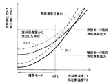
まず、室内蒸発器16の出口側の冷媒を冷却用冷媒と定義し、冷却用冷媒の温度を冷却用温度T1と定義し、冷却用冷媒の圧力を冷却用圧力P1と定義する。この際、本実施形態の冷却用膨張弁15aは、冷却用温度T1の変化に対応する冷却用圧力P1の変化が、図2の太実線に示す冷却用特性線CL1を描くように、より具体的には、冷却用特性線CL1に近づくように絞り開度を変化させる。
First, the refrigerant on the outlet side of the
本実施形態の冷却用特性線CL1は、図2の細一点鎖線で示す飽和蒸気圧線SLと略平行な線に設定されている。飽和蒸気圧線SLは、サイクルを循環する冷媒(本実施形態では、R134a)の物性によって決定される。さらに、冷却用圧力P1は、冷却用温度T1によらず、飽和蒸気圧よりも低い値になっている。 The cooling characteristic line CL1 of the present embodiment is set to a line substantially parallel to the saturated vapor pressure line SL shown by the fine alternate long and short dash line in FIG. The saturated vapor pressure line SL is determined by the physical properties of the refrigerant (R134a in this embodiment) that circulates in the cycle. Further, the cooling pressure P1 is lower than the saturated vapor pressure regardless of the cooling temperature T1.
このため、本実施形態の冷却用膨張弁15aの絞り開度特性では、冷却用温度T1によらず、冷却用冷媒を過熱度を有する気相状態となるように絞り開度を変化させる。より具体的には、冷却用膨張弁15aの絞り開度特性では、サイクルの通常運転時に、室内蒸発器16の出口側の冷媒の過熱度が概ね3℃となるように絞り開度を変化させる。
Therefore, in the throttle opening characteristic of the cooling
このような絞り開度特性は、冷却用膨張弁15aの感温部151aに封入される感温媒体として、サイクルを循環する冷媒を主成分とする媒体を採用することによって、実現することができる。つまり、冷却用膨張弁15aとして、いわゆるノーマルチャージ方式の温度式膨張弁を採用することによって、実現することができる。
Such a throttle opening characteristic can be realized by adopting a medium containing a refrigerant that circulates in the cycle as a main component as the temperature sensitive medium enclosed in the temperature
また、室外蒸発器18の出口側の冷媒を吸熱用冷媒と定義し、吸熱用冷媒の温度を吸熱用温度T2と定義し、吸熱用冷媒の圧力を吸熱用圧力P2と定義する。この際、本実施形態の吸熱用膨張弁15bは、吸熱用温度T2の変化に対応する吸熱用圧力P2の変化が、図2の太破線に示す吸熱用特性線CL2を描くように、より具体的には、吸熱用特性線CL2に近づくように絞り開度を変化させる。
Further, the refrigerant on the outlet side of the
ここで、図2から明らかなように、冷却用特性線CL1と吸熱用特性線CL2は、互いに異なっている。より詳細には、本実施形態では、吸熱用特性線CL2の傾きは、冷却用特性線CL1の傾きよりも小さくなっている。 Here, as is clear from FIG. 2, the cooling characteristic line CL1 and the endothermic characteristic line CL2 are different from each other. More specifically, in the present embodiment, the slope of the endothermic characteristic line CL2 is smaller than the slope of the cooling characteristic line CL1.
冷却用特性線CL1の傾きとは、冷却用圧力P1を冷却用温度T1の関数として冷却用特性線CL1を表した数式の微分値を採用することができる。吸熱用特性線CL2の傾きとは、吸熱用圧力P2を吸熱用温度T2の関数として冷却用特性線CL1を表した数式の微分値を採用することができる。 As the slope of the cooling characteristic line CL1, a differential value of a mathematical formula expressing the cooling characteristic line CL1 can be adopted with the cooling pressure P1 as a function of the cooling temperature T1. As the slope of the endothermic characteristic line CL2, a differential value of a mathematical formula representing the endothermic characteristic line CL1 can be adopted with the endothermic pressure P2 as a function of the endothermic temperature T2.
そして、冷却用温度T1および吸熱用温度T2が予め定めた基準温度KT2より低くなっている範囲では、吸熱用圧力P2が冷却用圧力P1および冷媒の飽和蒸気圧線によって決定される飽和圧力よりも高くなっている。 Then, in the range where the cooling temperature T1 and the heat absorbing temperature T2 are lower than the predetermined reference temperature KT2, the heat absorbing pressure P2 is higher than the saturation pressure determined by the cooling pressure P1 and the saturated vapor pressure line of the refrigerant. It's getting higher.
このため、本実施形態の吸熱用膨張弁15bの絞り開度特性では、吸熱用温度T2が基準温度KT2より低くなっている範囲では、吸熱用冷媒を気液二相状態となるように絞り開度を変化させる。さらに、吸熱用温度T2が基準温度KT2より高くなっている範囲では、吸熱用冷媒を過熱度有する気相状態となるように絞り開度を変化させる。
Therefore, in the throttle opening characteristic of the
このような絞り開度特性は、吸熱用膨張弁15bの感温部151bに封入される感温媒体として、サイクルを循環する冷媒とは異なる成分の冷媒に不活性ガスを混合させたもの等を採用することによって、実現することができる。つまり、吸熱用膨張弁15bとして、いわゆるクロスチャージ方式の温度式膨張弁を採用することによって、実現することができる。
Such a throttle opening characteristic is such that an inert gas is mixed with a refrigerant having a component different from that of the refrigerant circulating in the cycle as a temperature-sensitive medium sealed in the temperature-
さらに、本実施形態の基準温度KT2は、暖房モードの運転が実行される際の吸熱用温度T2が取り得る値よりも高い値(具体的には、1℃)に設定されている。このため、吸熱用膨張弁15bは、暖房モード時には、室外蒸発器18から流出した吸熱用冷媒が気液二相状態となるように絞り開度を変化させる。
Further, the reference temperature KT2 of the present embodiment is set to a value higher (specifically, 1 ° C.) than the value that the endothermic temperature T2 can take when the operation in the heating mode is executed. Therefore, in the heating mode, the
ここで、各蒸発器の出口側の冷媒は、各蒸発器の冷媒出口を通過する瞬間の冷媒のみを意味するものではなく、各蒸発器の出口側の冷媒には、室内蒸発器16の冷媒出口から流
出する直前の冷媒や、室内蒸発器16の冷媒出口から流出した直後の冷媒も含まれる。
Here, the refrigerant on the outlet side of each evaporator does not mean only the refrigerant at the moment of passing through the refrigerant outlet of each evaporator, and the refrigerant on the outlet side of each evaporator is the refrigerant of the
次に、室内空調ユニット50について説明する。室内空調ユニット50は、車両用空調装置1において、冷凍サイクル装置10によって温度調整された送風空気を車室内の適切な箇所へ吹き出すための空気通路を形成するものである。室内空調ユニット50は、車室内最前部の計器盤(すなわち、インストルメントパネル)の内側に配置されている。
Next, the indoor
室内空調ユニット50は、その外殻を形成するケーシング51の内部に形成される空気通路に、送風機52、室内蒸発器16、ヒータコア22等を収容したものである。
The indoor air-
ケーシング51は、車室内に送風される送風空気の空気通路を形成するもので、ある程度の弾性を有し、強度的にも優れた樹脂(具体的には、ポリプロピレン)にて成形されている。ケーシング51の送風空気流れ最上流側には、内外気切替装置53が配置されている。内外気切替装置53は、ケーシング51内へ内気(車室内空気)と外気(車室外空気)とを切替導入するものである。
The
内外気切替装置53は、ケーシング51内へ内気を導入させる内気導入口および外気を導入させる外気導入口の開口面積を、内外気切替ドアによって連続的に調整して、内気の導入風量と外気の導入風量との導入割合を変化させることができる。内外気切替ドアは、内外気切替ドア用の電動アクチュエータによって駆動される。この電動アクチュエータは、空調制御装置60から出力される制御信号によって、その作動が制御される。
The inside / outside
内外気切替装置53の送風空気流れ下流側には、送風機52が配置されている。送風機52は、内外気切替装置53を介して吸入した空気を車室内へ向けて送風する機能を果たす。送風機52は、遠心多翼ファンを電動モータにて駆動する電動送風機である。送風機52は、空調制御装置60から出力される制御電圧によって、回転数(すなわち、送風能力)が制御される。
A
送風機52の送風空気流れ下流側には、室内蒸発器16およびヒータコア22が、送風空気の流れに対して、この順に配置されている。つまり、室内蒸発器16は、ヒータコア22よりも送風空気流れ上流側に配置されている。
On the downstream side of the blower air flow of the
また、ケーシング51内には、室内蒸発器16を通過した送風空気を、ヒータコア22を迂回させて下流側へ流す冷風バイパス通路55が形成されている。
Further, a cold
室内蒸発器16の送風空気流れ下流側であって、かつ、ヒータコア22の送風空気流れ上流側には、エアミックスドア54が配置されている。エアミックスドア54は、室内蒸発器16を通過後の送風空気のうち、ヒータコア22を通過させる風量と冷風バイパス通路55を通過させる風量との風量割合を調整するものである。
An
エアミックスドア54は、エアミックスドア駆動用の電動アクチュエータによって駆動される。この電動アクチュエータは、空調制御装置60から出力される制御信号によって、その作動が制御される。
The
ヒータコア22の送風空気流れ下流側には、ヒータコア22にて加熱された送風空気と冷風バイパス通路55を通過してヒータコア22にて加熱されていない送風空気とを混合させる混合空間56が設けられている。さらに、ケーシング51の送風空気流れ最下流部には、混合空間56にて混合された送風空気(空調風)を、車室内へ吹き出す開口穴が配置されている。
A mixing
この開口穴としては、フェイス開口穴、フット開口穴、およびデフロスタ開口穴(いずれも図示せず)が設けられている。フェイス開口穴は、車室内の乗員の上半身に向けて空調風を吹き出すための開口穴である。フット開口穴は、乗員の足元に向けて空調風を吹き出すための開口穴である。デフロスタ開口穴は、車両前面窓ガラス内側面に向けて空調風を吹き出すための開口穴である。 As the opening hole, a face opening hole, a foot opening hole, and a defroster opening hole (none of which are shown) are provided. The face opening hole is an opening hole for blowing air-conditioning air toward the upper body of the occupant in the vehicle interior. The foot opening hole is an opening hole for blowing air-conditioning air toward the feet of the occupant. The defroster opening hole is an opening hole for blowing air conditioning air toward the inner surface of the front window glass of the vehicle.
これらのフェイス開口穴、フット開口穴、およびデフロスタ開口穴は、それぞれ空気通路を形成するダクトを介して、車室内に設けられたフェイス吹出口、フット吹出口およびデフロスタ吹出口(いずれも図示せず)に接続されている。 These face opening holes, foot opening holes, and defroster opening holes are provided in the vehicle interior through ducts forming air passages, respectively, and face outlets, foot outlets, and defroster outlets (none of which are shown). )It is connected to the.
従って、エアミックスドア54が、ヒータコア22を通過させる風量と冷風バイパス通路55を通過させる風量との風量割合を調整することによって、混合空間にて混合される空調風の温度が調整される。これにより、各吹出口から車室内へ吹き出される送風空気(空調風)の温度も調整される。
Therefore, the temperature of the conditioned air mixed in the mixing space is adjusted by adjusting the air volume ratio between the air volume passing through the
また、フェイス開口穴、フット開口穴、およびデフロスタ開口穴の送風空気流れ上流側には、それぞれ、フェイス開口穴の開口面積を調整するフェイスドア、フット開口穴の開口面積を調整するフットドア、デフロスタ開口穴の開口面積を調整するデフロスタドア(いずれも図示せず)が配置されている。 Further, on the upstream side of the blast air flow of the face opening hole, the foot opening hole, and the defroster opening hole, a face door for adjusting the opening area of the face opening hole, a foot door for adjusting the opening area of the foot opening hole, and a defroster opening, respectively. A defroster door (neither shown) is arranged to adjust the opening area of the hole.
これらのフェイスドア、フットドア、デフロスタドアは、空調風が吹き出される吹出口を切り替える吹出モード切替装置を構成するものである。フェイスドア、フットドア、デフロスタドアは、リンク機構等を介して、吹出口モードドア駆動用の電動アクチュエータに連結されて連動して回転操作される。この電動アクチュエータは、空調制御装置60から出力される制御信号によって、その作動が制御される。
These face doors, foot doors, and defroster doors constitute an outlet mode switching device that switches the outlet from which the air conditioner air is blown out. The face door, foot door, and defroster door are connected to an electric actuator for driving the outlet mode door via a link mechanism or the like, and are rotated in conjunction with each other. The operation of this electric actuator is controlled by a control signal output from the air
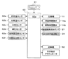
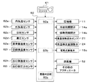
次に、図3を用いて、本実施形態の電気制御部の概要について説明する。空調制御装置60は、CPU、ROMおよびRAM等を含む周知のマイクロコンピュータとその周辺回路から構成されている。そして、そのROM内に記憶された空調制御プログラムに基づいて各種演算、処理を行い、その出力側に接続された各種制御対象機器11、14a、14b、21、24、52、等の作動を制御する。
Next, the outline of the electric control unit of the present embodiment will be described with reference to FIG. The air
また、空調制御装置60の入力側には、図3のブロック図に示すように、内気温センサ62a、外気温センサ62b、日射センサ62c、高圧センサ62d、蒸発器温度センサ62e、空調風温度センサ62f等の空調制御用のセンサ群が接続されている。空調制御装置60には、これらの空調制御用のセンサ群の検出信号が入力される。
Further, on the input side of the air
内気温センサ62aは、車室内温度(内気温)Trを検出する内気温検出部である。外気温センサ62bは、車室外温度(外気温)Tamを検出する外気温検出部である。日射センサ62cは、車室内へ照射される日射量Asを検出する日射量検出部である。高圧センサ62dは、圧縮機11の吐出口側から冷却用膨張弁15aあるいは吸熱用膨張弁15bの入口側へ至る冷媒流路の高圧冷媒圧力Pdを検出する冷媒圧力検出部である。
The internal
蒸発器温度センサ62eは、室内蒸発器16における冷媒蒸発温度(蒸発器温度)Tefinを検出する蒸発器温度検出部である。空調風温度センサ62fは、混合空間56から車室内へ送風される送風空気温度TAVを検出する空調風温度検出部である。
The evaporator temperature sensor 62e is an evaporator temperature detection unit that detects the refrigerant evaporation temperature (evaporator temperature) Tefin in the
さらに、空調制御装置60の入力側には、図3に示すように、車室内前部の計器盤付近に配置された操作パネル61が接続され、この操作パネル61に設けられた各種操作スイッチからの操作信号が入力される。
Further, as shown in FIG. 3, an
操作パネル61に設けられた各種操作スイッチとしては、具体的に、車両用空調装置の自動制御運転を設定あるいは解除するオートスイッチ、車室内の冷房を行うことを要求する冷房スイッチ、送風機52の風量をマニュアル設定する風量設定スイッチ、車室内の目標温度Tsetを設定する温度設定スイッチ等がある。
Specific examples of the various operation switches provided on the
なお、本実施形態の空調制御装置60は、その出力側に接続された各種制御対象機器を制御する制御部が一体に構成されたものであるが、それぞれの制御対象機器の作動を制御する構成(ハードウェアおよびソフトウェア)が、それぞれの制御対象機器の作動を制御する制御部を構成している。例えば、空調制御装置60のうち、圧縮機11の作動を制御する構成は、吐出能力制御部60aである。
The air-
次に、上記構成における本実施形態の車両用空調装置1の作動について説明する。上述の如く、本実施形態の車両用空調装置1では運転モードを切り替えることができる。これらの運転モードの切り替えは、空調制御装置60に予め記憶された空調制御プログラムが実行されることによって行われる。
Next, the operation of the
より具体的には、空調制御プログラムでは、空調制御用のセンサ群によって検出された検出信号および操作パネル61から出力される操作信号に基づいて、車室内へ送風させる送風空気の目標吹出温度TAOを算出する。そして、目標吹出温度TAOおよび検出信号に基づいて、運転モードを切り替える。以下に、各運転モードの作動を説明する。
More specifically, in the air conditioning control program, the target blowing temperature TAO of the blown air to be blown into the vehicle interior is set based on the detection signal detected by the sensor group for air conditioning control and the operation signal output from the
(a)冷房モード
冷房モードでは、空調制御装置60が、冷却用開閉弁14aを開き、吸熱用開閉弁14bを閉じる。
(A) Cooling mode In the cooling mode, the air
従って、冷房モードの冷凍サイクル装置10では、圧縮機11→高温側水−冷媒熱交換器12→分岐部13a→冷却用開閉弁14a→冷却用膨張弁15a→室内蒸発器16→蒸発圧力調整弁17→合流部13b→圧縮機11の順で冷媒が循環する蒸気圧縮式の冷凍サイクルが構成される。
Therefore, in the
つまり、冷房モードでは、室内蒸発器16へ冷媒を流入させる冷媒回路に切り替えられる。換言すると、冷房モードでは、冷却用蒸発器へ冷媒が流入することが許容される冷媒回路に切り替えられる。
That is, in the cooling mode, it is switched to the refrigerant circuit that allows the refrigerant to flow into the
そして、このサイクル構成で、空調制御装置60は、出力側に接続された各種制御対象機器の作動を制御する。
Then, in this cycle configuration, the air
例えば、空調制御装置60は、蒸発器温度センサ62eによって検出された冷媒蒸発温度Tefinが目標蒸発温度TEOとなるように圧縮機11の作動を制御する。目標蒸発温度TEOは、目標吹出温度TAOに基づいて、予め空調制御装置60に記憶された冷房モード用の制御マップを参照して決定される。
For example, the air
具体的には、この制御マップでは、空調風温度センサ62fによって検出された送風空気温度TAVが目標吹出温度TAOに近づくように、目標吹出温度TAOの上昇に伴って目標蒸発温度TEOを上昇させる。さらに、目標蒸発温度TEOは、室内蒸発器16の着霜を抑制可能な範囲(具体的には、1℃以上)の値に決定される。
Specifically, in this control map, the target evaporation temperature TEO is increased as the target outlet temperature TAO increases so that the blown air temperature TAV detected by the air conditioning
また、空調制御装置60は、予め定めた冷房モード時の水圧送能力を発揮するように、高温側熱媒体ポンプ21を作動させる。また、空調制御装置60は、高温側水−冷媒熱交換器12の水通路から流出した高温側熱媒体の全流量が高温側ラジエータ23へ流入するように、高温側流量調整弁24の作動を制御する。
Further, the air
また、空調制御装置60は、目標吹出温度TAOに基づいて、予め空調制御装置60に記憶された制御マップを参照して送風機52の制御電圧(送風能力)を決定する。具体的には、この制御マップでは、目標吹出温度TAOの極低温域(最大冷房域)および極高温域(最大暖房域)で送風機52の送風量を最大とし、中間温度域に近づくに伴って送風量を減少させる。
Further, the air
また、空調制御装置60は、冷風バイパス通路55を全開としてヒータコア22側の通風路を閉塞するように、エアミックスドア54の作動を制御する。また、空調制御装置60は、その他の各種制御対象機器についても、適宜その作動を制御する。
Also, the
従って、冷房モードの冷凍サイクル装置10では、圧縮機11から吐出された高圧冷媒が、高温側水−冷媒熱交換器12へ流入する。高温側水−冷媒熱交換器12では、高温側熱媒体ポンプ21が作動しているので、高圧冷媒と高温側熱媒体が熱交換して、高圧冷媒が冷却されて凝縮し、高温側熱媒体が加熱される。
Therefore, in the refrigerating
高温側熱媒体回路20では、高温側水−冷媒熱交換器12にて加熱された高温側熱媒体が、高温側流量調整弁24を介して、高温側ラジエータ23へ流入する。高温側ラジエータ23へ流入した高温側熱媒体は、外気と熱交換して放熱する。これにより、高温側熱媒体が冷却される。高温側ラジエータ23にて冷却された高温側熱媒体は、高温側熱媒体ポンプ21に吸入されて再び高温側水−冷媒熱交換器12の水通路へ圧送される。
In the high-temperature side
高温側水−冷媒熱交換器12の冷媒通路にて冷却された高圧冷媒は、分岐部13aおよび冷却用開閉弁14aを介して、冷却用膨張弁15aへ流入して減圧される。この際、冷却用膨張弁15aの絞り開度は、冷却用温度T1に対する冷却用圧力P1が、図2に示す冷却用特性線CL1に近づくように調整される。つまり、冷却用膨張弁15aの絞り開度は、室内蒸発器16の出口側の冷媒の過熱度が概ね3℃となるように調整される。
The high-pressure refrigerant cooled in the refrigerant passage of the high-temperature side water-
冷却用膨張弁15aにて減圧された低圧冷媒は、室内蒸発器16へ流入する。室内蒸発器16へ流入した冷媒は、送風機52から送風された送風空気から吸熱して蒸発する。これにより、送風空気が冷却される。室内蒸発器16から流出した冷媒は、蒸発圧力調整弁17および合流部13bを介して、圧縮機11へ吸入されて再び圧縮される。
The low-pressure refrigerant decompressed by the cooling
従って、冷房モードでは、室内蒸発器16にて冷却された送風空気を車室内へ吹き出すことによって、車室内の冷房を行うことができる。
Therefore, in the cooling mode, the interior of the vehicle can be cooled by blowing the blown air cooled by the
(b)暖房モード
暖房モードでは、空調制御装置60が、冷却用開閉弁14aを閉じ、吸熱用開閉弁14bを開く。
(B) Heating mode In the heating mode, the air
従って、暖房モードの冷凍サイクル装置10では、圧縮機11→高温側水−冷媒熱交換器12→分岐部13a→吸熱用開閉弁14b→吸熱用膨張弁15b→室外蒸発器18→合流部13b→圧縮機11の順で冷媒が循環する蒸気圧縮式の冷凍サイクルが構成される。
Therefore, in the
つまり、暖房モードでは、室内蒸発器16へ冷媒を流入させない冷媒回路に切り替えられる。換言すると、冷却用蒸発器へ冷媒が流入することが禁止される冷媒回路に切り替えられる。
That is, in the heating mode, it is switched to the refrigerant circuit that does not allow the refrigerant to flow into the
そして、このサイクル構成で、空調制御装置60は、出力側に接続された各種制御対象機器の作動を制御する。
Then, in this cycle configuration, the air
例えば、空調制御装置60は、高圧センサ62dによって検出された高圧冷媒圧力Pdが目標高圧PCOとなるように圧縮機11の作動を制御する。目標高圧PCOは、目標吹出温度TAOに基づいて、予め空調制御装置60に記憶された暖房モード用の制御マップを参照して決定される。
For example, the air
具体的には、この制御マップでは、送風空気温度TAVが目標吹出温度TAOに近づくように、目標吹出温度TAOの上昇に伴って目標高圧PCOを上昇させる。 Specifically, in this control map, the target high pressure PCO is increased as the target outlet temperature TAO increases so that the blown air temperature TAV approaches the target outlet temperature TAO.
また、空調制御装置60は、予め定めた暖房モード時の水圧送能力を発揮するように、高温側熱媒体ポンプ21を作動させる。また、空調制御装置60は、高温側水−冷媒熱交換器12の水通路から流出した高温側熱媒体の全流量がヒータコア22へ流入するように、高温側流量調整弁24の作動を制御する。
Further, the air
また、空調制御装置60は、冷房モードと同様に、送風機52の制御電圧(送風能力)を決定する。また、空調制御装置60は、ヒータコア22側の通風路を全開として冷風バイパス通路55を閉塞するように、エアミックスドア54の作動を制御する。また、空調制御装置60は、その他の各種制御対象機器についても、適宜その作動を制御する。
Further, the air
従って、暖房モードの冷凍サイクル装置10では、圧縮機11から吐出された高圧冷媒が、高温側水−冷媒熱交換器12へ流入する。高温側水−冷媒熱交換器12では、高温側熱媒体ポンプ21が作動しているので、高圧冷媒と高温側熱媒体が熱交換して、高圧冷媒が冷却されて凝縮し、高温側熱媒体が加熱される。
Therefore, in the refrigerating
高温側熱媒体回路20では、高温側水−冷媒熱交換器12にて加熱された高温側熱媒体が、高温側流量調整弁24を介して、ヒータコア22へ流入する。ヒータコア22へ流入した高温側熱媒体は、エアミックスドア54がヒータコア22側の通風路を全開としているので、室内蒸発器16を通過した送風空気と熱交換して放熱する。
In the high temperature side
これにより、送風空気が加熱されて、送風空気の温度が目標吹出温度TAOに近づく。ヒータコア22から流出した高温側熱媒体は、高温側熱媒体ポンプ21に吸入されて再び高温側水−冷媒熱交換器12の水通路へ圧送される。
As a result, the blown air is heated, and the temperature of the blown air approaches the target blowing temperature TAO. The high-temperature side heat medium flowing out of the
高温側水−冷媒熱交換器12の冷媒通路から流出した高圧冷媒は、分岐部13aおよび吸熱用開閉弁14bを介して、吸熱用膨張弁15bへ流入して減圧される。この際、吸熱用膨張弁15bの絞り開度は、吸熱用温度T2に対する吸熱用圧力P2が、図2に示す吸熱用特性線CL2に近づくように調整される。
The high-pressure refrigerant flowing out of the refrigerant passage of the high-temperature side water-
前述の如く、吸熱用特性線CL2では、暖房モードの運転が実行される際の吸熱用温度T2が基準温度KT2よりも低い値となる。このため、吸熱用圧力P2が冷媒の飽和圧力よりも高くなる。つまり、吸熱用膨張弁15bの絞り開度は、室外蒸発器18の出口側の冷媒が気液二相状態となるように調整される。
As described above, in the endothermic characteristic line CL2, the endothermic temperature T2 when the operation in the heating mode is executed is lower than the reference temperature KT2. Therefore, the endothermic pressure P2 becomes higher than the saturation pressure of the refrigerant. That is, the throttle opening of the
吸熱用膨張弁15bにて減圧された低圧冷媒は、室外蒸発器18へ流入する。室外蒸発器18へ流入した冷媒は、外気ファンから送風された熱源流体である外気から吸熱して蒸発する。室外蒸発器18から流出した冷媒は、合流部13bを介して、圧縮機11へ吸入されて再び圧縮される。
The low-pressure refrigerant decompressed by the
従って、暖房モードでは、ヒータコア22で加熱された送風空気を車室内へ吹き出すことによって、車室内の暖房を行うことができる。また、暖房モードは、室内蒸発器16へ冷媒を流入させない冷媒回路に切り替えられ、かつ、吸熱用温度T2が基準温度KT2よりも低い値になっているという予め定めた条件が成立している運転モードである。
Therefore, in the heating mode, the interior of the vehicle can be heated by blowing the blown air heated by the
(c)除湿暖房モード
除湿暖房モードでは、空調制御装置60が、冷却用開閉弁14aを開き、吸熱用開閉弁14bを開く。
(C) Dehumidifying and heating mode In the dehumidifying and heating mode, the air
従って、除湿暖房モードの冷凍サイクル装置10では、圧縮機11→高温側水−冷媒熱交換器12→分岐部13a→冷却用開閉弁14a→冷却用膨張弁15a→室内蒸発器16→蒸発圧力調整弁17→合流部13b→圧縮機11の順で冷媒が循環するとともに、圧縮機11→高温側水−冷媒熱交換器12→分岐部13a→吸熱用開閉弁14b→吸熱用膨張弁15b→室外蒸発器18→合流部13b→圧縮機11の順で冷媒が循環する蒸気圧縮式の冷凍サイクルが構成される。
Therefore, in the
つまり、除湿暖房モードでは、室内蒸発器16および室外蒸発器18が、冷媒流れに対して並列的に接続される冷媒回路に切り替えられる。さらに、冷房モードでは、室内蒸発器16へ冷媒を流入させる冷媒回路に切り替えられる。
That is, in the dehumidifying / heating mode, the
そして、このサイクル構成で、空調制御装置60は、出力側に接続された各種制御対象機器の作動を制御する。
Then, in this cycle configuration, the air
例えば、空調制御装置60は、暖房モードと同様に圧縮機11の作動を制御する。また、空調制御装置60は、予め定めた除湿暖房モード時の水圧送能力を発揮するように、高温側熱媒体ポンプ21を作動させる。また、空調制御装置60は、暖房モードと同様に、高温側水−冷媒熱交換器12の水通路から流出した高温側熱媒体の全流量がヒータコア22へ流入するように、高温側流量調整弁24の作動を制御する。
For example, the air
また、空調制御装置60は、冷房モードおよび暖房モードと同様に、送風機52の制御電圧(送風能力)を決定する。また、空調制御装置60は、暖房モードと同様にヒータコア22側の通風路を全開として冷風バイパス通路55を閉塞するように、エアミックスドア54の作動を制御する。また、空調制御装置60は、その他の各種制御対象機器へ出力される制御信号についても適宜決定する。
Further, the air
従って、除湿暖房モードの冷凍サイクル装置10では、圧縮機11から吐出された高温高圧の冷媒が、高温側水−冷媒熱交換器12へ流入する。高温側水−冷媒熱交換器12では、高温側熱媒体ポンプ21が作動しているので、高圧冷媒と高温側熱媒体が熱交換して、高圧冷媒が冷却されて凝縮し、高温側熱媒体が加熱される。
Therefore, in the refrigerating
高温側熱媒体回路20では、暖房モードと同様に、高温側水−冷媒熱交換器12にて加熱された高温側熱媒体が、高温側流量調整弁24を介して、ヒータコア22へ流入する。ヒータコア22へ流入した高温側熱媒体は、暖房モードと同様に、室内蒸発器16を通過した送風空気と熱交換して放熱する。
In the high temperature side
これにより、室内蒸発器16を通過した送風空気が加熱されて、送風空気の温度が目標吹出温度TAOに近づく。ヒータコア22から流出した高温側熱媒体は、高温側熱媒体ポンプ21に吸入されて再び高温側水−冷媒熱交換器12の水通路へ圧送される。
As a result, the blown air that has passed through the
高温側水−冷媒熱交換器12の冷媒通路から流出した高圧冷媒は、分岐部13aにて分岐される。分岐部13aにて分岐された一方の冷媒は、冷房モードと同様に、冷却用膨張弁15aへ流入して減圧される。この際、冷却用膨張弁15aの絞り開度は、室内蒸発器16の出口側の冷媒の過熱度が3℃となるように調整される。
The high-pressure refrigerant flowing out from the refrigerant passage of the high-temperature side water-
冷却用膨張弁15aにて減圧された低圧冷媒は、室内蒸発器16へ流入する。室内蒸発器16へ流入した冷媒は、送風機52から送風された送風空気から吸熱して蒸発する。これにより、送風空気が冷却されて除湿される。この際、室内蒸発器16における冷媒蒸発温度は、圧縮機11の冷媒吐出能力によらず、蒸発圧力調整弁17の作用によって、1℃以上に維持される。
The low-pressure refrigerant decompressed by the cooling
室内蒸発器16から流出した冷媒は、蒸発圧力調整弁17を介して合流部13bの一方の冷媒流入口へ流入する。
The refrigerant flowing out of the
分岐部13aにて分岐された他方の冷媒は、暖房モードと同様に、吸熱用膨張弁15bへ流入して減圧される。この際、吸熱用膨張弁15bの絞り開度は、室外蒸発器18の出口側の冷媒が気液二相状態となるように調整される。
The other refrigerant branched at the
吸熱用膨張弁15bにて減圧された低圧冷媒は、室外蒸発器18へ流入する。室外蒸発器18へ流入した冷媒は、外気ファンから送風された外気から吸熱して蒸発する。室外蒸発器18から流出した冷媒は、合流部13bの他方の冷媒流入口へ流入する。
The low-pressure refrigerant decompressed by the
合流部13bでは、室内蒸発器16から流出した過熱度を有する気相状態の冷媒と室外蒸発器18から流出した気液二相状態の冷媒が合流する。本実施形態では、合流した冷媒が飽和気相冷媒に近づくように、分岐部13aの各通路における流量係数、室内蒸発器16熱交換性能、室外蒸発器18の熱交換性能が設定されている。合流部13bから流出した冷媒は、圧縮機11へ吸入されて再び圧縮される。
At the merging
従って、除湿暖房モードでは、室内蒸発器16にて冷却されて除湿された送風空気を、ヒータコア22で再加熱して車室内へ吹き出すことによって、車室内の除湿暖房を行うことができる。
Therefore, in the dehumidifying / heating mode, the dehumidifying / heating of the vehicle interior can be performed by reheating the blown air cooled by the
以上の如く、本実施形態の車両用空調装置1によれば、冷凍サイクル装置10が冷媒回路を切り替えることによって、冷房モード、暖房モード、除湿暖房モードを切り替えることができ、車室内の快適な空調を実現することができる。
As described above, according to the
ここで、本実施形態のように、運転モードに応じて、冷媒回路を切り替える冷凍サイクル装置10では、サイクル構成の複雑化を招きやすい。
Here, in the refrigerating
これに対して、本実施形態の冷凍サイクル装置10では、同一の熱交換器へ高圧冷媒を流入させる冷媒回路と低圧冷媒を流入させる冷媒回路とを切り替えることがない。つまり、いずれの冷媒回路に切り替えても室内蒸発器16および室外蒸発器18へ高圧冷媒を流入させる必要がないので、サイクル構成の複雑化を招くことなく簡素な構成で冷媒回路を切り替えることができる。
On the other hand, in the
また、運転モードを切替可能に構成された冷凍サイクル装置では、蒸発器として機能する熱交換器の出口側の冷媒の状態を、運転モードに応じて適切に調整しなければならない。 Further, in the refrigeration cycle apparatus configured to be able to switch the operation mode, the state of the refrigerant on the outlet side of the heat exchanger functioning as an evaporator must be appropriately adjusted according to the operation mode.
これに対して、本実施形態では、図2に示すように、冷却用膨張弁15aの絞り開度特性を示す冷却用特性線CL1、および吸熱用膨張弁15bの絞り開度特性を示す吸熱用特性線CL2が互いに異なっている。従って、室内蒸発器16から流出した冷却用冷媒の状態、および室外蒸発器18から流出した吸熱用冷媒の状態をそれぞれ適切な状態に調整することができる。
On the other hand, in the present embodiment, as shown in FIG. 2, the cooling characteristic line CL1 showing the throttle opening characteristic of the cooling
具体的には、図2に示すように、基準温度KT2は、室内蒸発器16へ冷媒を流入させない冷媒回路に切り替えられる暖房モード時に、吸熱用温度T2が基準温度KT2よりも低くなるように設定されている。従って、暖房モード時に、吸熱用圧力P2を冷媒の飽和圧力よりも高い値とすることができ、吸熱用冷媒を気液二相状態とすることができる。
Specifically, as shown in FIG. 2, the reference temperature KT2 is set so that the endothermic temperature T2 is lower than the reference temperature KT2 in the heating mode in which the refrigerant circuit is switched so that the refrigerant does not flow into the
従って、暖房モードのように、室外蒸発器18における冷媒蒸発温度を外気温よりも低下させる必要があり、サイクルを循環する循環冷媒流量が減少しやすい運転モードであっても、室外蒸発器18内に冷凍機油が滞留してしまうことを抑制することができる。
Therefore, it is necessary to lower the refrigerant evaporation temperature in the
さらに、本実施形態の冷却用特性線CL1では、冷却用圧力P1を冷媒の飽和圧力よりも低い値とすることができ、冷却用冷媒を過熱度を有する気相状態とすることができる。従って、冷房モードや除湿暖房モードのように、室内蒸発器16へ冷媒を流入させる冷媒回路に切り替えられた際には、室内蒸発器16にて冷媒を気化潜熱によって送風空気を効率的に冷却することができる。
Further, in the cooling characteristic line CL1 of the present embodiment, the cooling pressure P1 can be set to a value lower than the saturation pressure of the refrigerant, and the cooling refrigerant can be put into a gas phase state having a degree of superheat. Therefore, when the refrigerant circuit is switched to allow the refrigerant to flow into the
すなわち、本実施形態の冷凍サイクル装置10では、サイクル構成の複雑化を招くことなく冷媒回路を切り替えることができる。さらに、運転モードに応じて、冷却用蒸発器である室内蒸発器16、および吸熱用蒸発器である室外蒸発器18の出口側の冷媒の状態を適切に調整することができる。
That is, in the refrigerating
また、本実施形態の冷凍サイクル装置10では、冷却用膨張弁15aとしてノーマルチャージ方式の温度式膨張弁を採用し、吸熱用膨張弁15bとしてクロスチャージ方式の温度式膨張弁を採用している。従って、冷却用膨張弁15aおよび吸熱用膨張弁15bの制御態様を複雑化させることなく、機械的機構によって、極めて容易に、室内蒸発器16および室外蒸発器18から流出した冷媒の状態を適切に調整することができる。
Further, in the
また、本実施形態の冷凍サイクル装置10では、水−冷媒熱交換器12を備え、高温側熱媒体を循環させる高温側熱媒体回路20に、ヒータコア22を配置している。従って、暖房モード時および除湿暖房モード時に、水−冷媒熱交換器12にて加熱された高温側熱媒体をヒータコア22へ流入させて、送風空気を加熱することができる。
Further, in the
さらに、ヒータコア22へ均一の温度の高圧側熱媒体を流入させることができ、ヒータコアにて加熱される送風空気に温度分布が生じてしまうことを抑制することができる。
Further, the high-pressure side heat medium having a uniform temperature can be flowed into the
また、本実施形態の冷凍サイクル装置10では、高温側熱媒体回路20に、高温側ラジエータ23が配置されている。従って、送風空気から吸熱した熱を外気に放熱させることができ、車室内の冷房を行うことができる。
Further, in the
(第2実施形態)
本実施形態では、第1実施形態に対して、図4の全体構成図に示すように、内部熱交換器19を追加した例を説明する。なお、図4では、第1実施形態と同一もしくは均等部分には同一の符号を付している。このことは、以下の図面でも同様である。
(Second Embodiment)
In the present embodiment, an example in which the
具体的には、内部熱交換器19は、高圧側冷媒通路を流通する冷媒と低圧側冷媒通路を流通する冷媒とを熱交換させる熱交換器である。高圧側冷媒通路を流通する冷媒は、水−冷媒熱交換器12の冷媒通路から流出した高圧冷媒である。低圧側冷媒通路を流通する冷媒は、室外蒸発器18から流出した冷媒であって、合流部13bの冷媒流出口から流出した低圧冷媒である。
Specifically, the
また、本実施形態では、図5に示すように、吸熱用膨張弁15bの絞り開度特性が決定されている。
Further, in the present embodiment, as shown in FIG. 5, the throttle opening characteristic of the
より詳細には、内部熱交換器19の出口側の低圧冷媒の温度を低圧側温度T3と定義し、当該低圧冷媒の圧力を低圧側圧力P3と定義する。この際、本実施形態の吸熱用膨張弁15bは、低圧側温度T3の変化に対応する低圧側圧力P3の変化が、図5の太破線に示す低圧側特性線CL3を描くように、より具体的には、低圧側特性線CL3に近づくように絞り開度を変化させる。
More specifically, the temperature of the low-pressure refrigerant on the outlet side of the
ここで、図5から明らかなように、低圧側特性線CL3は、第1実施形態の図2で説明した吸熱用特性線CL2と同様の線を描いている。従って、冷却用特性線CL1と低圧側特性線CL3は、互いに異なっている。さらに、低圧側特性線CL3の傾きは、冷却用特性線CL1の傾きよりも小さくなっている。 Here, as is clear from FIG. 5, the low-voltage side characteristic line CL3 draws the same line as the endothermic characteristic line CL2 described with reference to FIG. 2 of the first embodiment. Therefore, the cooling characteristic line CL1 and the low pressure side characteristic line CL3 are different from each other. Further, the slope of the low-voltage side characteristic line CL3 is smaller than the slope of the cooling characteristic line CL1.
そして、冷却用温度T1および低圧側温度T3が予め定めた基準温度KT3より低くなっている範囲では、低圧側圧力P3が冷却用圧力P1および冷媒の飽和圧力よりも高くなっている。 In the range where the cooling temperature T1 and the low pressure side temperature T3 are lower than the predetermined reference temperature KT3, the low pressure side pressure P3 is higher than the cooling pressure P1 and the saturation pressure of the refrigerant.
このため、本実施形態の吸熱用膨張弁15bの絞り開度特性では、低圧側温度T3が基準温度KT3より低くなっている範囲では、吸熱用冷媒を気液二相状態となるように絞り開度を変化させる。さらに、低圧側温度T3が基準温度KT3より高くなっている範囲では、吸熱用冷媒を過熱度有する気相状態となるように絞り開度を変化させる。
Therefore, in the throttle opening characteristic of the
さらに、本実施形態の基準温度KT3は、暖房モードの運転が実行される際の低圧側温度T3が取り得る値よりも高い値(具体的には、1℃)に設定されている。このため、吸熱用膨張弁15bは、暖房モード時には、内部熱交換器19の出口側の低圧冷媒が気液二相状態となるように絞り開度を変化させる。
Further, the reference temperature KT3 of the present embodiment is set to a value higher (specifically, 1 ° C.) than the value that the low pressure side temperature T3 can take when the operation in the heating mode is executed. Therefore, in the heating mode, the
なお、図5の細一点鎖線は、冷媒の飽和蒸気圧線SLであり、細二点鎖線は、室外蒸発器18から流出した直後の吸熱用冷媒の吸熱用温度T2と吸熱用圧力P2との関係を示した特性線である。その他の構成は第1実施形態と同様である。
The fine alternate long and short dash line in FIG. 5 is the saturated vapor pressure line SL of the refrigerant, and the fine alternate long and short dash line is the endothermic temperature T2 and the endothermic pressure P2 of the endothermic refrigerant immediately after flowing out from the
次に、上記構成における本実施形態の車両用空調装置1の作動について説明する。本実施形態の車両用空調装置1においても、第1実施形態と同様に、空調制御プログラムが実行されることによって、運転モードが切り替えられる。以下に、各運転モードの作動を説明する。
Next, the operation of the
(a)冷房モード
冷房モードでは、空調制御装置60が、第1実施形態と同様に、冷却用開閉弁14aを開き、吸熱用開閉弁14bを閉じる。
(A) Cooling mode In the cooling mode, the air
従って、冷房モードの冷凍サイクル装置10では、圧縮機11→高温側水−冷媒熱交換器12→内部熱交換器19の高圧側冷媒通路→分岐部13a→冷却用開閉弁14a→冷却用膨張弁15a→室内蒸発器16→蒸発圧力調整弁17→合流部13b→内部熱交換器19の低圧側冷媒通路→圧縮機11の順で冷媒が循環する蒸気圧縮式の冷凍サイクルが構成される。
Therefore, in the
そして、このサイクル構成で、空調制御装置60は、第1実施形態の冷房モードと同様に、出力側に接続された各種制御対象機器の作動を制御する。従って、冷房モードでは、実質的に第1実施形態と同様に、室内蒸発器16にて冷却された送風空気を車室内へ吹き出すことによって、車室内の冷房を行うことができる。
Then, in this cycle configuration, the air
(b)暖房モード
暖房モードでは、空調制御装置60が、第1実施形態と同様に、冷却用開閉弁14aを閉じ、吸熱用開閉弁14bを開く。
(B) Heating mode In the heating mode, the air
従って、暖房モードの冷凍サイクル装置10では、圧縮機11→高温側水−冷媒熱交換器12→内部熱交換器19の高圧側冷媒通路→分岐部13a→吸熱用開閉弁14b→吸熱用膨張弁15b→室外蒸発器18→合流部13b→内部熱交換器19の低圧側冷媒通路→圧縮機11の順で冷媒が循環する蒸気圧縮式の冷凍サイクルが構成される。
Therefore, in the
そして、このサイクル構成で、空調制御装置60は、第1実施形態の暖房モードと同様に、出力側に接続された各種制御対象機器の作動を制御する。
Then, in this cycle configuration, the air
従って、暖房モードの冷凍サイクル装置10では、圧縮機11から吐出された高圧冷媒が、高温側水−冷媒熱交換器12へ流入する。これにより、第1実施形態の暖房モードと同様に、ヒータコア22にて、送風空気が加熱されて、送風空気の温度が目標吹出温度TAOに近づく。
Therefore, in the refrigerating
高温側水−冷媒熱交換器12の冷媒通路から流出した高圧冷媒は、内部熱交換器19の高圧側冷媒通路へ流入する。内部熱交換器19の高圧側冷媒通路へ流入した高圧冷媒は、内部熱交換器19の低圧側冷媒通路を流通する低圧冷媒と熱交換して、エンタルピを低下させる。
The high-pressure refrigerant flowing out of the high-temperature side water-
内部熱交換器19の高圧側冷媒通路から流出した高圧冷媒は、分岐部13aおよび吸熱用開閉弁14bを介して、吸熱用膨張弁15bへ流入して減圧される。この際、吸熱用膨張弁15bの絞り開度は、低圧側温度T3に対する低圧側圧力P3が、図5に示す低圧側特性線CL3に近づくように調整される。
The high-pressure refrigerant flowing out of the high-pressure side refrigerant passage of the
吸熱用膨張弁15bにて減圧された低圧冷媒は、室外蒸発器18へ流入する。室外蒸発器18へ流入した冷媒は、外気ファンから送風された熱源流体である外気から吸熱して蒸発する。室外蒸発器18から流出した冷媒は、合流部13bを介して、内部熱交換器19の低圧側冷媒通路へ流入する。
The low-pressure refrigerant decompressed by the
内部熱交換器19の低圧側冷媒通路へ流入した低圧冷媒は、内部熱交換器19の高圧側冷媒通路を流通する高圧冷媒と熱交換して、エンタルピを上昇させる。内部熱交換器19の低圧側冷媒通路から流出した低圧冷媒は、圧縮機11へ吸入されて再び圧縮される。
The low-pressure refrigerant that has flowed into the low-pressure side refrigerant passage of the
従って、暖房モードでは、ヒータコア22で加熱された送風空気を車室内へ吹き出すことによって、車室内の暖房を行うことができる。
Therefore, in the heating mode, the interior of the vehicle can be heated by blowing the blown air heated by the
(c)除湿暖房モード
除湿暖房モードでは、空調制御装置60が、第1実施形態と同様に、冷却用開閉弁14aを開き、吸熱用開閉弁14bを開く。
(C) Dehumidifying and heating mode In the dehumidifying and heating mode, the air
従って、除湿暖房モードの冷凍サイクル装置10では、圧縮機11→高温側水−冷媒熱交換器12→内部熱交換器19の高圧側冷媒通路→分岐部13a→冷却用開閉弁14a→冷却用膨張弁15a→室内蒸発器16→蒸発圧力調整弁17→合流部13b→内部熱交換器19の低圧側冷媒通路→圧縮機11の順で冷媒が循環するとともに、圧縮機11→高温側水−冷媒熱交換器12→内部熱交換器19の高圧側冷媒通路→分岐部13a→吸熱用開閉弁14b→吸熱用膨張弁15b→室外蒸発器18→合流部13b→内部熱交換器19の低圧側冷媒通路→圧縮機11の順で冷媒が循環する蒸気圧縮式の冷凍サイクルが構成される。
Therefore, in the
そして、このサイクル構成で、空調制御装置60は、第1実施形態の除湿暖房モードと同様に、出力側に接続された各種制御対象機器の作動を制御する。
Then, in this cycle configuration, the air
従って、除湿暖房モードの冷凍サイクル装置10では、圧縮機11から吐出された高圧冷媒が、高温側水−冷媒熱交換器12へ流入する。これにより、第1実施形態の除湿暖房モードと同様に、ヒータコア22にて、室内蒸発器16を通過した送風空気が加熱されて、送風空気の温度が目標吹出温度TAOに近づく。
Therefore, in the refrigerating
高温側水−冷媒熱交換器12の冷媒通路から流出した高圧冷媒は、内部熱交換器19の高圧側冷媒通路へ流入する。内部熱交換器19の高圧側冷媒通路へ流入した高圧冷媒は、暖房モードと同様に、内部熱交換器19の低圧側冷媒通路を流通する低圧冷媒と熱交換して、エンタルピを低下させる。
The high-pressure refrigerant flowing out of the high-temperature side water-
内部熱交換器19の高圧側冷媒通路から流出した高圧冷媒は、分岐部13aにて分岐される。分岐部13aにて分岐された一方の冷媒は、冷房モードと同様に、冷却用膨張弁15aへ流入して減圧される。この際、冷却用膨張弁15aの絞り開度は、室内蒸発器16の出口側の冷媒の過熱度が3℃となるように調整される。
The high-pressure refrigerant flowing out of the high-pressure side refrigerant passage of the
冷却用膨張弁15aにて減圧された低圧冷媒は、室内蒸発器16へ流入する。室内蒸発器16へ流入した冷媒は、送風機52から送風された送風空気から吸熱して蒸発する。これにより、第1実施形態と同様に、送風空気が冷却されて除湿される。室内蒸発器16から流出した冷媒は、蒸発圧力調整弁17を介して合流部13bの一方の冷媒流入口へ流入する。
The low-pressure refrigerant decompressed by the cooling
分岐部13aにて分岐された他方の冷媒は、暖房モードと同様に、吸熱用膨張弁15bへ流入して減圧される。この際、吸熱用膨張弁15bの絞り開度は、内部熱交換器19の低圧側冷媒通路の出口側の冷媒が気液二相状態となるように調整される。
The other refrigerant branched at the
吸熱用膨張弁15bにて減圧された低圧冷媒は、室外蒸発器18へ流入する。室外蒸発器18へ流入した冷媒は、外気ファンから送風された外気から吸熱して蒸発する。室外蒸発器18から流出した冷媒は、合流部13bの他方の冷媒流入口へ流入する。
The low-pressure refrigerant decompressed by the
合流部13bでは、室内蒸発器16から流出した過熱度を有する気相状態の冷媒と室外蒸発器18から流出した気液二相状態の冷媒が合流する。合流部13bの冷媒流出口から流出した冷媒は内部熱交換器19の低圧側冷媒通路へ流入する。
At the merging
内部熱交換器19の低圧側冷媒通路へ流入した低圧冷媒は、内部熱交換器19の高圧側冷媒通路を流通する高圧冷媒と熱交換して、エンタルピを上昇させる。内部熱交換器19の低圧側冷媒通路から流出した低圧冷媒は、圧縮機11へ吸入されて再び圧縮される。
The low-pressure refrigerant that has flowed into the low-pressure side refrigerant passage of the
従って、除湿暖房モードでは、室内蒸発器16にて冷却されて除湿された送風空気を、ヒータコア22で再加熱して車室内へ吹き出すことによって、車室内の除湿暖房を行うことができる。
Therefore, in the dehumidifying / heating mode, the dehumidifying / heating of the vehicle interior can be performed by reheating the blown air cooled by the
以上の如く、本実施形態の車両用空調装置1によれば、冷凍サイクル装置10が冷媒回路を切り替えることによって、運転モードを切り替えて、車室内の快適な空調を実現することができる。
As described above, according to the
さらに、本実施形態の冷凍サイクル装置10によれば、第1実施形態と同様に、サイクル構成の複雑化を招くことなく簡素な構成で冷媒回路を切り替えることができる。これに加えて、運転モードに応じて、冷却用蒸発器である室内蒸発器16、および吸熱用蒸発器である室外蒸発器18の出口側の冷媒の状態を適切に調整することができる。
Further, according to the refrigerating
具体的には、図5に示すように、基準温度KT3は、室内蒸発器16へ冷媒を流入させない冷媒回路に切り替えられる暖房モード時に、低圧側温度T3が基準温度KT3よりも低くなるように設定されている。従って、暖房モード時に、低圧側圧力P3を冷媒の飽和圧力よりも高い値とすることができ、内部熱交換器19の低圧側冷媒通路から流出した低圧冷媒を気液二相状態とすることができる。
Specifically, as shown in FIG. 5, the reference temperature KT3 is set so that the low pressure side temperature T3 is lower than the reference temperature KT3 in the heating mode in which the refrigerant circuit is switched to prevent the refrigerant from flowing into the
従って、暖房モードのように、サイクルを循環する循環冷媒流量が減少しやすい運転モードであっても、室外蒸発器18内および内部熱交換器19内に冷凍機油が滞留してしまうことを抑制することができる。
Therefore, even in the operation mode in which the flow rate of the circulating refrigerant circulating in the cycle is likely to decrease, such as the heating mode, it is possible to prevent the refrigerating machine oil from staying in the
さらに、冷却用特性線CL1については、第1実施形態と同様に、冷却用冷媒を過熱度を有する気相状態とすることができる。従って、冷房モードや除湿暖房モードのように、室内蒸発器16へ冷媒を流入させる冷媒回路に切り替えられた際には、室内蒸発器16にて冷媒を気化潜熱によって送風空気を効率的に冷却することができる。
Further, with respect to the cooling characteristic line CL1, the cooling refrigerant can be put into a gas phase state having a degree of superheat, as in the first embodiment. Therefore, when the refrigerant circuit is switched to allow the refrigerant to flow into the
また、本実施形態の冷凍サイクル装置10では、内部熱交換器19を備えているので、室内蒸発器16および室外蒸発器18へ流入する冷媒のエンタルピを低下させることができる。従って、蒸発器として機能する熱交換器における冷媒の冷却能力を増大させて、冷凍サイクル装置10の成績係数(COP)を向上させることができる。
Further, since the
さらに、本実施形態の冷凍サイクル装置10では、同一の熱交換器へ高圧冷媒を流入させる冷媒回路と低圧冷媒を流入させる冷媒回路とを切り替えることがない。従って、いずれの運転モードの冷媒回路においても、内部熱交換器19を備えることによるCOP向上効果を得ることができる。
Further, in the
(第3実施形態)
本実施形態では、第1実施形態に対して、図6の全体構成図に示すように、室外蒸発器18を廃止して、チラー18a、低温側熱媒体回路30等を採用した例を説明する。
(Third Embodiment)
In the present embodiment, as shown in the overall configuration diagram of FIG. 6, an example in which the
チラー18aは、少なくとも暖房モード時および除湿暖房モード時に、吸熱用膨張弁15bにて減圧された低圧冷媒と低温側熱媒体回路30を循環する低温側熱媒体とを熱交換させる低温側水−冷媒熱交換器である。さらに、チラー18aは、低圧冷媒を蒸発させて吸熱作用を発揮させる吸熱用蒸発器である。従って、本実施形態の熱源流体は低温側熱媒体である。チラー18aは、車両ボンネット内の前方側に配置されている。
The
チラー18aは、吸熱用膨張弁15bにて減圧された低圧冷媒を流通させる冷媒通路を有している。チラー18aの冷媒通路の出口には、合流部13bの他方の冷媒流入口側が接続されている。また、チラー18aは、低温側熱媒体回路30を循環する低温側熱媒体を流通させる水通路を有している。低温側熱媒体としては、エチレングリコールを含む溶液、不凍液等を採用することができる。
The
ここで、低温側熱媒体回路30は、低温側熱媒体を循環させる低温側の水回路である。低温側熱媒体回路30には、チラー18aの水通路、低温側熱媒体ポンプ31、車載機器32の冷却部、低温側ラジエータ33、低温側流量調整弁34等が配置されている。
Here, the low temperature side
低温側熱媒体ポンプ31は、低温側熱媒体回路30において、低温側熱媒体をチラー18aの水通路の入口側へ圧送する低温側水ポンプである。低温側熱媒体ポンプ31の基本的構成は、高温側熱媒体ポンプ21と同様の電動ポンプである。従って、低温側熱媒体ポンプ31は、空調制御装置60から出力される制御電圧によって、回転数(すなわち、水圧送能力)が制御される。
The low temperature side
車載機器32は、作動時に発熱を伴う発熱機器であり、本実施形態の車載機器は、走行用電動モータに電量を供給するバッテリである。また、車載機器32の冷却部とは、充放電時のような作動時にバッテリが発生させた熱を低圧側熱媒体に吸熱させるために、バッテリ内に形成された熱媒体通路を意味している。
The in-
低温側ラジエータ33は、チラー18aにて冷却された低温側熱媒体と図示しない外気ファンから送風された外気とを熱交換させて、低温側熱媒体に外気の有する熱を吸熱させる熱交換器である。低温側ラジエータ33は、車両ボンネット内の前方側に配置されている。低温側ラジエータ33は、チラー18a等と一体的に形成されていてもよい。
The low
車載機器32の冷却部および低温側ラジエータ33は、図6に示すように、低温側熱媒体回路30において、低温側熱媒体の流れに対して並列的に接続されている。
As shown in FIG. 6, the cooling unit and the low
低温側流量調整弁34は、車載機器32の冷却部へ流入する低温側熱媒体の流量と低温側ラジエータ33へ流入する低温側熱媒体の流量との低温側流量比を連続的に調整する電気式の三方流量調整弁である。低温側流量調整弁34の基本的構成は、高温側流量調整弁24と同様である。低温側流量調整弁34は、空調制御装置60から出力される制御信号によって、その作動が制御される。
The low temperature side flow
低温側流量調整弁34は、車載機器32の冷却部の熱媒体入口側と低温側ラジエータ33の熱媒体入口側との接続部に配置されている。つまり、チラー18aの水通路の出口には、低温側流量調整弁34の入口側が接続されている。低温側流量調整弁34の一方の出口には、車載機器32の冷却部の熱媒体入口側が接続されている。低温側流量調整弁34の他方の出口には、低温側ラジエータ33の熱媒体入口側が接続されている。
The low temperature side flow
従って、低温側熱媒体回路30では、低温側流量調整弁34が低温側流量比を調整することによって、車載機器32の冷却部における低温側熱媒体の車載機器32からの吸熱量、および低温側ラジエータ33における低温側熱媒体の外気からの吸熱量を調整することができる。
Therefore, in the low temperature side
また、本実施形態の空調制御装置60の入力側には、図7に示すように、車載機器32であるバッテリの温度BTを検出する電池温度センサ62gが接続されている。その他の構成は、第1実施形態と同様である。
Further, as shown in FIG. 7, a
次に、上記構成における本実施形態の車両用空調装置1の作動について説明する。本実施形態の車両用空調装置1においても、第1実施形態と同様に、空調制御プログラムが実行されることによって、運転モードが切り替えられる。以下に、各運転モードの作動を説明する。
Next, the operation of the
(a)冷房モード
冷房モードでは、空調制御装置60が、第1実施形態と同様に、冷却用開閉弁14aを開き、吸熱用開閉弁14bを閉じる。従って、第1実施形態の冷房モードと全く同様の冷凍サイクルが構成される。
(A) Cooling mode In the cooling mode, the air
さらに、冷房モードでは、空調制御装置60が、低温側熱媒体ポンプ31を停止させる。その他の制御対象機器については、第1実施形態の冷房モードと同様に制御する。従って、第1実施形態と全く同様に、車室内の冷房を行うことができる。
Further, in the cooling mode, the air
(b)暖房モード
暖房モードでは、空調制御装置60が、第1実施形態と同様に、冷却用開閉弁14aを閉じ、吸熱用開閉弁14bを開く。
(B) Heating mode In the heating mode, the air
従って、暖房モードの冷凍サイクル装置10では、圧縮機11→高温側水−冷媒熱交換器12→分岐部13a→吸熱用開閉弁14b→吸熱用膨張弁15b→チラー18a→合流部13b→圧縮機11の順で冷媒が循環する蒸気圧縮式の冷凍サイクルが構成される。
Therefore, in the
さらに、暖房モードでは、空調制御装置60が、予め定めた暖房モード時の水圧送能力を発揮するように、低温側熱媒体ポンプ31を作動させる。
Further, in the heating mode, the air
また、空調制御装置60は、電池温度センサ62gによって検出されたバッテリの温度BTを参照して、バッテリが適切な充放電性能を発揮可能な温度範囲内に維持されるように、低温側流量調整弁34の作動を制御する。その他の制御対象機器については、第1実施形態の暖房モードと同様に制御する。
Further, the
従って、暖房モードの冷凍サイクル装置10では、圧縮機11から吐出された高圧冷媒が、高温側水−冷媒熱交換器12へ流入する。これにより、第1実施形態の暖房モードと同様に、ヒータコア22にて、送風空気が加熱されて、送風空気の温度が目標吹出温度TAOに近づく。
Therefore, in the refrigerating
高温側水−冷媒熱交換器12の冷媒通路から流出した高圧冷媒は、第1実施形態の暖房モードと同様に、分岐部13aおよび吸熱用開閉弁14bを介して、吸熱用膨張弁15bへ流入して減圧される。従って、吸熱用膨張弁15bの絞り開度は、チラー18aの出口側の冷媒が気液二相状態となるように調整される。
The high-pressure refrigerant flowing out of the refrigerant passage of the high-temperature side water-
吸熱用膨張弁15bにて減圧された低圧冷媒は、チラー18aの冷媒通路へ流入する。チラー18aでは、低温側熱媒体ポンプ31が作動しているので、低圧冷媒と低温側熱媒体が熱交換して、低圧冷媒が低温側熱媒体から吸熱して蒸発する。これにより、低温側熱媒体が冷却される。従って、本実施形態の熱源流体は低圧側熱媒体である。
The low-pressure refrigerant decompressed by the
低温側熱媒体回路30では、チラー18aにて冷却された一部の低温側熱媒体が、低温側流量調整弁34を介して、低温側ラジエータ33へ流入する。低温側ラジエータ33へ流入した低温側熱媒体は、外気と熱交換して加熱される。チラー18aにて冷却された残余の低温側熱媒体は、低温側流量調整弁34を介して、車載機器32であるバッテリの冷却部へ流入して加熱される。
In the low temperature side
この際、低温側流量調整弁34は、車載機器32であるバッテリが適切な充放電性能を発揮できる温度となるように、低温側流量比を調整する。低温側ラジエータ33から流出した低温側熱媒体および車載機器32の冷却部から流出した低温側熱媒体は、高温側熱媒体ポンプ21に吸入され、再びチラー18aの水通路へ圧送される。
At this time, the low temperature side flow
チラー18aの冷媒通路から流出した冷媒は、合流部13bを介して、圧縮機11へ吸入されて再び圧縮される。
The refrigerant flowing out of the refrigerant passage of the
従って、暖房モードでは、ヒータコア22で加熱された送風空気を車室内へ吹き出すことによって、車室内の暖房を行うことができる。
Therefore, in the heating mode, the interior of the vehicle can be heated by blowing the blown air heated by the
(c)除湿暖房モード
除湿暖房モードは、空調制御装置60が、第1実施形態と同様に、冷却用開閉弁14aを開き、吸熱用開閉弁14bを開く。
(C) Dehumidifying and heating mode In the dehumidifying and heating mode, the air
従って、除湿暖房モードの冷凍サイクル装置10では、圧縮機11→高温側水−冷媒熱交換器12→分岐部13a→冷却用開閉弁14a→冷却用膨張弁15a→室内蒸発器16→蒸発圧力調整弁17→合流部13b→圧縮機11の順で冷媒が循環するとともに、圧縮機11→高温側水−冷媒熱交換器12→分岐部13a→吸熱用開閉弁14b→吸熱用膨張弁15b→チラー18a→合流部13b→圧縮機11の順で冷媒が循環する蒸気圧縮式の冷凍サイクルが構成される。
Therefore, in the
さらに、除湿暖房モードでは、空調制御装置60は、予め定めた暖房モード時の水圧送能力を発揮するように、低温側熱媒体ポンプ31を作動させる。また、空調制御装置60は、暖房モードと同様に、バッテリが適切な充放電性能を発揮可能な温度範囲内に維持されるように、低温側流量調整弁34の作動を制御する。その他の制御対象機器については、第1実施形態の除湿暖房モードと同様に制御する。
Further, in the dehumidifying heating mode, the air
従って、除湿暖房モードの冷凍サイクル装置10では、圧縮機11から吐出された高圧冷媒が、高温側水−冷媒熱交換器12へ流入する。これにより、第1実施形態の除湿暖房モードと同様に、ヒータコア22にて、室内蒸発器16を通過した送風空気が加熱されて、送風空気の温度が目標吹出温度TAOに近づく。
Therefore, in the refrigerating
高温側水−冷媒熱交換器12の冷媒通路から流出した高圧冷媒の流れは、分岐部13aにて分岐される。分岐部13aにて分岐された一方の冷媒は、冷房モードと同様に、冷却用膨張弁15aへ流入して減圧される。冷却用膨張弁15aにて減圧された低圧冷媒は、室内蒸発器16へ流入する。室内蒸発器16へ流入した冷媒は、送風機52から送風された送風空気から吸熱して蒸発する。これにより送風空気が冷却される。
The flow of the high-pressure refrigerant flowing out from the refrigerant passage of the high-temperature side water-
この際、室内蒸発器16における冷媒蒸発温度は、圧縮機11の冷媒吐出能力によらず、蒸発圧力調整弁17の作用によって、1℃以上に維持される。
At this time, the refrigerant evaporation temperature in the
一方、分岐部13aにて分岐された他方の冷媒は、暖房モードと同様に、吸熱用膨張弁15bへ流入して減圧される。冷却用膨張弁15aにて減圧された低圧冷媒は、チラー18aの冷媒通路へ流入する。チラー18aでは、暖房モードと同様に、低温側熱媒体ポンプ31が作動しているので、低圧冷媒と低温側熱媒体が熱交換して、低圧冷媒が低温側熱媒体から吸熱して蒸発する。
On the other hand, the other refrigerant branched at the
低温側熱媒体回路30では、暖房モードと同様に、低温側熱媒体が外気および車載機器32であるバッテリから吸熱する。チラー18aの冷媒通路から流出した冷媒は、合流部13bにて蒸発圧力調整弁17から流出した冷媒と合流し、圧縮機11へ吸入されて再び圧縮される。
In the low temperature side
従って、除湿暖房モードでは、室内蒸発器16にて冷却されて除湿された送風空気をヒータコア22で再加熱して車室内へ吹き出すことによって、車室内の除湿暖房を行うことができる。
Therefore, in the dehumidifying / heating mode, the dehumidifying / heating of the vehicle interior can be performed by reheating the blown air cooled by the
以上の如く、本実施形態の車両用空調装置1によれば、冷凍サイクル装置10が冷媒回路を切り替えることによって、冷房モード、暖房モード、除湿暖房モードを切り替えることができ、車室内の快適な空調を実現することができる。
As described above, according to the
さらに、本実施形態の冷凍サイクル装置10によれば、第1実施形態と同様に、サイクル構成の複雑化を招くことなく簡素な構成で冷媒回路を切り替えることができる。これに加えて、運転モードに応じて、冷却用蒸発器である室内蒸発器16、および吸熱用蒸発器であるチラー18aから流出した冷媒の状態を適切に調整することができる。
Further, according to the refrigerating
また、本実施形態の冷凍サイクル装置10では、チラー18aを備え、低温側熱媒体を循環させる低温側熱媒体回路30に、車載機器32であるバッテリの冷却部、および低温側ラジエータ33が配置されている。そして、暖房モード時および除湿暖房モード時に、吸熱用膨張弁15bにて減圧された冷媒をチラー18aへ流入させる。
Further, in the
これによれば、暖房モード時および除湿暖房モード時に、車載機器32の廃熱あるいは外気によって加熱された低温側熱媒体の有する熱を冷媒に吸熱させ、冷媒が吸熱した熱を熱源として、確実に送風空気を加熱することができる。さらに、車載機器32を冷却することもできる。
According to this, in the heating mode and the dehumidifying heating mode, the heat of the low-temperature side heat medium heated by the waste heat of the in-
(第4実施形態)
本実施形態では、第1実施形態に対して、図8の全体構成図に示すように、高温側水−冷媒熱交換器12、高温側熱媒体回路20等を廃止して、加熱部としての室内凝縮器12aおよび室外熱交換器12bを採用した例を説明する。
(Fourth Embodiment)
In the present embodiment, as shown in the overall configuration diagram of FIG. 8, the high temperature side water-
室内凝縮器12aは、圧縮機11から吐出された高温高圧の冷媒と送風空気とを熱交換させて、送風空気を加熱する熱交換器である。室内凝縮器12aは、室内空調ユニット50のケーシング51内であって、第1実施形態で説明したヒータコア22と同様の位置に配置されている。
The
室外熱交換器12bは、室内凝縮器12aから流出した冷媒と図示しない外気ファンから送風された外気とを熱交換させて、冷媒の有する熱を外気に放熱させる熱交換器である。室外熱交換器12bは、車両ボンネット内の前方側に配置されている。さらに、室外熱交換器12bの外気流れ上流側には、室外熱交換器12bにて外気を流通させる外気風路を開閉するシャッター機構12cが配置されている。
The
このため、シャッター機構12cが外気通路を閉塞している際には、室外熱交換器12bにて冷媒と外気との熱交換は行われない。シャッター機構12cは、空調制御装置60から出力される制御信号によって、その作動が制御される。その他の構成は、第1実施形態と同様である。
Therefore, when the
次に、上記構成における本実施形態の車両用空調装置1の作動について説明する。本実施形態の車両用空調装置1においても、第1実施形態と同様に、空調制御プログラムが実行されることによって、運転モードが切り替えられる。以下に、各運転モードの作動を説明する。
Next, the operation of the
(a)冷房モード
冷房モードでは、空調制御装置60が、第1実施形態と同様に、冷却用開閉弁14aを開き、吸熱用開閉弁14bを閉じる。
(A) Cooling mode In the cooling mode, the air
従って、冷房モードの冷凍サイクル装置10では、圧縮機11→室内凝縮器12a→室外熱交換器12b→分岐部13a→冷却用開閉弁14a→冷却用膨張弁15a→室内蒸発器16→蒸発圧力調整弁17→合流部13b→圧縮機11の順で冷媒が循環する蒸気圧縮式の冷凍サイクルが構成される。
Therefore, in the
さらに、冷房モードでは、空調制御装置60が、室外熱交換器12bの外気通路を開くように、シャッター機構12cの作動を制御する。その他の制御対象機器については、第1実施形態の冷房モードと同様に制御する。
Further, in the cooling mode, the air
従って、冷房モードの冷凍サイクル装置10では、圧縮機11から吐出された高温高圧の冷媒が、室内凝縮器12aへ流入する。冷房モードでは、エアミックスドア54が冷風バイパス通路55を全開として、室内凝縮器12a側の通風路を閉塞している。このため、室内凝縮器12aへ流入した冷媒は、殆ど送風空気へ放熱することなく、室内凝縮器12aから流出して室外熱交換器12bへ流入する。
Therefore, in the refrigerating
室外熱交換器12bへ流入した冷媒は、シャッター機構12cが室外熱交換器12bの外気通路を開いているので、外気に放熱して凝縮する。室外熱交換器12bから流出した冷媒は、分岐部13aおよび冷却用開閉弁14aを介して、冷却用膨張弁15aへ流入して減圧される。以降の作動は、第1実施形態の冷房モードと同様である。
The refrigerant that has flowed into the
従って、冷房モードでは、室内蒸発器16にて冷却された送風空気を車室内へ吹き出すことによって、車室内の冷房を行うことができる。
Therefore, in the cooling mode, the interior of the vehicle can be cooled by blowing the blown air cooled by the
(b)暖房モード
暖房モードでは、空調制御装置60が、冷却用開閉弁14aを閉じ、吸熱用開閉弁14bを開く。
(B) Heating mode In the heating mode, the air
従って、暖房モードの冷凍サイクル装置10では、圧縮機11→室内凝縮器12a→室外熱交換器12b→分岐部13a→吸熱用開閉弁14b→吸熱用膨張弁15b→室外蒸発器18→合流部13b→圧縮機11の順で冷媒が循環する蒸気圧縮式の冷凍サイクルが構成される。
Therefore, in the
さらに、暖房モードでは、空調制御装置60が、室外熱交換器12bの外気通路を閉塞するように、シャッター機構12cの作動を制御する。その他の制御対象機器については、第1実施形態の暖房モードと同様に制御する。
Further, in the heating mode, the air
従って、暖房モードの冷凍サイクル装置10では、圧縮機11から吐出された高温高圧の冷媒が、室内凝縮器12aへ流入する。暖房モードでは、エアミックスドア54が冷風バイパス通路55を閉塞して、室内凝縮器12a側の通風路を全開としている。このため、室内凝縮器12aへ流入した冷媒は、送風空気に放熱して凝縮する。これにより、送風空気が加熱されて、送風空気の温度が目標吹出温度TAOに近づく。
Therefore, in the refrigerating
室内凝縮器12aから流出した冷媒は、室外熱交換器12bへ流入する。室外熱交換器12bへ流入した冷媒は、シャッター機構12cが室外熱交換器12bの外気通路を閉塞しているので、殆ど外気へ放熱することなく、室外熱交換器12bから流出する。
The refrigerant flowing out of the
室外熱交換器12bから流出した冷媒は、分岐部13aおよび吸熱用開閉弁14bを介して、吸熱用膨張弁15bへ流入して減圧される。以降の作動は、第1実施形態の暖房モードと同様である。
The refrigerant flowing out of the
従って、暖房モードでは、室内凝縮器12aで加熱された送風空気を車室内へ吹き出すことによって、車室内の暖房を行うことができる。
Therefore, in the heating mode, the interior of the vehicle can be heated by blowing the blown air heated by the
(c)除湿暖房モード
除湿暖房モードでは、空調制御装置60が、冷却用開閉弁14aを閉じ、吸熱用開閉弁14bを開く。
(C) Dehumidifying and heating mode In the dehumidifying and heating mode, the air
従って、除湿暖房モードの冷凍サイクル装置10では、圧縮機11→室内凝縮器12a→室外熱交換器12b→分岐部13a→冷却用開閉弁14a→冷却用膨張弁15a→室内蒸発器16→蒸発圧力調整弁17→合流部13b→圧縮機11の順で冷媒が循環するとともに、圧縮機11→室内凝縮器12a→室外熱交換器12b→分岐部13a→吸熱用開閉弁14b→吸熱用膨張弁15b→室外蒸発器18→合流部13b→圧縮機11の順で冷媒が循環する蒸気圧縮式の冷凍サイクルが構成される。
Therefore, in the
さらに、暖房モードでは、空調制御装置60が、室外熱交換器12bの外気通路を閉塞するように、シャッター機構12cの作動を制御する。その他の制御対象機器については、第1実施形態の除湿暖房モードと同様に制御する。
Further, in the heating mode, the air
従って、除湿暖房モードの冷凍サイクル装置10では、圧縮機11から吐出された高温高圧の冷媒が、室内凝縮器12aへ流入する。室内凝縮器12aへ流入した高温高圧の冷媒は、暖房モードと同様に、室内蒸発器16を通過した送風空気と熱交換して放熱する。これにより、送風空気が加熱されて、送風空気の温度が目標吹出温度TAOに近づく。
Therefore, in the
室内凝縮器12aから流出した冷媒は、室外熱交換器12bへ流入する。室外熱交換器12bへ流入した冷媒は、シャッター機構12cが室外熱交換器12bの外気通路を閉塞しているので、殆ど外気へ放熱することなく、室外熱交換器12bから流出する。
The refrigerant flowing out of the
室外熱交換器12bから流出した冷媒は、分岐部13aにて分岐される。分岐部13aにて分岐された一方の冷媒は、冷房モードと同様に、冷却用膨張弁15aへ流入して減圧される。分岐部13aにて分岐された他方の冷媒は、暖房モードと同様に、吸熱用膨張弁15bへ流入して減圧される。以降の作動は、第1実施形態の除湿暖房モードと同様である。
The refrigerant flowing out of the
従って、除湿暖房モードでは、室内蒸発器16にて冷却されて除湿された送風空気を、室内凝縮器12aで再加熱して車室内へ吹き出すことによって、車室内の除湿暖房を行うことができる。
Therefore, in the dehumidifying / heating mode, the dehumidifying / heating of the vehicle interior can be performed by reheating the blown air cooled by the
以上の如く、本実施形態の車両用空調装置1によれば、冷凍サイクル装置10が冷媒回路を切り替えることによって、冷房モード、暖房モード、除湿暖房モードを切り替えることができ、車室内の快適な空調を実現することができる。
As described above, according to the
さらに、本実施形態の冷凍サイクル装置10によれば、第1実施形態と同様に、サイクル構成の複雑化を招くことなく簡素な構成で冷媒回路を切り替えることができる。これに加えて、運転モードに応じて、冷却用蒸発器である室内蒸発器16、および吸熱用蒸発器である室外蒸発器18から流出した冷媒の状態を適切に調整することができる。
Further, according to the refrigerating
また、本実施形態の冷凍サイクル装置10では、室内凝縮器12aを備えている。従って、暖房モード時および除湿暖房モード時に、圧縮機11から吐出された高温高圧の冷媒と送風空気とを直接的に熱交換させて、送風空気を加熱することができる。また、本実施形態の冷凍サイクル装置10では、室外熱交換器12bを備えている。従って、送風空気から吸熱した熱を外気に放熱させることができ、車室内の冷房を行うことができる。
Further, the
(第5実施形態)
本実施形態では、第1実施形態に対して、図9の全体構成図に示すように、吸熱用開閉弁14bを廃止して、吸熱用減圧部として電気的機構によって絞り開度を変化させる電気式の吸熱用膨張弁15c(以下、電気式膨張弁15cと記載する。)を採用した例を説明する。
(Fifth Embodiment)
In the present embodiment, as shown in the overall configuration diagram of FIG. 9, with respect to the first embodiment, the endothermic on-off
電気式膨張弁15cは、分岐部13aの他方の冷媒流出口から流出した冷媒を減圧させる吸熱用減圧部である。電気式膨張弁15cは、絞り開度を変更可能に構成された弁体と、この弁体の開度を変化させる電動アクチュエータ(具体的には、ステッピングモータ)とを有して構成される電気式の可変絞り機構である。
The
電気式膨張弁15cは、空調制御装置60から出力される制御信号(制御パルス)によって、その作動が制御される。さらに、電気式膨張弁15cは、弁開度を全閉とすることで冷媒通路を閉塞する全閉機能を有している。従って、本実施形態の電気式膨張弁15cは、回路切替部としての機能を兼ね備えている。
The operation of the
また、本実施形態の空調制御装置60の入力側には、図10に示すように、出口側温度センサ62h、および出口側圧力センサ62iが接続されている。出口側温度センサ62hは、室外蒸発器18の出口側の冷媒の出口側温度Te1を検出する出口側温度検出部である。出口側圧力センサ62iは、室外蒸発器18の出口側の冷媒の出口側圧力Pe1を検出する出口側圧力検出部である。
Further, as shown in FIG. 10, an outlet side temperature sensor 62h and an outlet side pressure sensor 62i are connected to the input side of the air
また、本実施形態の空調制御装置60のうち、電気式膨張弁15cの作動を制御する構成は、吸熱用膨張弁制御部60bである。そして、吸熱用膨張弁制御部60bは、暖房モードおよび除湿暖房モードの通常運転時には、吸熱用温度T2の変化に対応する吸熱用圧力P2の変化が、第1実施形態で説明した図2の太破線に示す吸熱用特性線CL2に近づくように、電気式膨張弁15cの作動を制御する。
Further, in the air
ここで、図2の吸熱用特性線CL2では、吸熱用温度T2が基準温度KT2より低くなっている範囲で、吸熱用冷媒が気液二相状態となるように吸熱用減圧部の絞り開度を変化させる。 Here, in the endothermic characteristic line CL2 of FIG. 2, the throttle opening of the endothermic decompression section is set so that the endothermic refrigerant is in a gas-liquid two-phase state within a range where the endothermic temperature T2 is lower than the reference temperature KT2. To change.
ところが、気液二相状態の冷媒の乾き度等を正確に検出することは難しい。そこで、本実施形態の空調制御装置60では、出口側温度センサ62hによって検出された出口側温度Te1、出口側圧力センサ62iによって検出された出口側圧力Pe1のみならず、その他のセンサの検出信号に基づいて、予め空調制御装置60に記憶された制御マップを参照して電気式膨張弁15cの作動を制御する。
However, it is difficult to accurately detect the dryness of the refrigerant in a gas-liquid two-phase state. Therefore, in the air
これにより、本実施形態の吸熱用膨張弁制御部60bは、吸熱用温度T2の変化に対応する吸熱用圧力P2の変化が、吸熱用特性線CL2に近づくように電気式膨張弁15cの作動を制御している。従って、本実施形態の冷凍サイクル装置10では、第1実施形態と同様に、冷房モード、暖房モード、除湿暖房モードを切り替えることができ、車室内の快適な空調を実現することができる。
As a result, the endothermic expansion
さらに、本実施形態の冷凍サイクル装置10によれば、第1実施形態と同様に、サイクル構成の複雑化を招くことなく簡素な構成で冷媒回路を切り替えることができる。これに加えて、運転モードに応じて、冷却用蒸発器である室内蒸発器16、および吸熱用蒸発器である室外蒸発器18の出口側の冷媒の状態を適切に調整することができる。
Further, according to the refrigerating
ところで、暖房モードおよび除湿暖房モードでは、室外蒸発器18における冷媒蒸発温度を外気温よりも低下させる必要がある。このため、暖房モードおよび除湿暖房モードでは、室外蒸発器18に着霜が生じてしまうおそれがある。そこで、本実施形態の冷凍サイクル装置10では、室外蒸発器18に着霜が生じていると判定された際に、除霜モードの運転を行う。
By the way, in the heating mode and the dehumidifying heating mode, it is necessary to lower the refrigerant evaporation temperature in the
より詳細には、本実施形態の空調制御装置60は、着霜判定部60cを有している。着霜判定部60cは、室外蒸発器18に着霜が生じているか否かを判定する制御プログラムである。着霜判定部60cは、空調制御プログラムのサブルーチンとして所定の周期毎に実行される。
More specifically, the air
具体的には、本実施形態の着霜判定部は、出口側温度センサ62hによって検出された出口側温度Te1が、外気温センサによって検出された外気温Tamから予め定めた基準温度αを減算した値よりも低くなっている際に、室外熱交換器16に着霜が生じていると判定する制御プログラムを採用している。
Specifically, in the frost formation determination unit of the present embodiment, the outlet side temperature Te1 detected by the outlet side temperature sensor 62h subtracts a predetermined reference temperature α from the outside air temperature Tam detected by the outside air temperature sensor. A control program for determining that frost has formed on the
そして、暖房モードおよび除湿暖房モードの実行中に、着霜判定部60cが室外蒸発器18に着霜が生じていると判定すると、除霜モードの運転が実行される。除霜モードでは、空調制御装置60が電気式膨張弁15cの絞り開度を増加させる。これにより、室外蒸発器18へ流入する冷媒の温度を上昇させて、室外蒸発器18に生じた霜を融解して除霜することができる。除霜モードは、予め定めた基準除霜時間が経過するまで継続される。
Then, if the frost
以上の如く、本実施形態では、吸熱用減圧部として、電気式膨張弁15cを採用しているので、電気式膨張弁15cの絞り開度を変更することで、除霜モードを実行することができる。
As described above, in the present embodiment, since the
(他の実施形態)
本発明は上述の実施形態に限定されることなく、本発明の趣旨を逸脱しない範囲内で、以下のように種々変形可能である。
(Other embodiments)
The present invention is not limited to the above-described embodiment, and can be variously modified as follows without departing from the spirit of the present invention.
(1)上述の実施形態では、本発明に係る冷凍サイクル装置10を電気自動車用の空調装置に適用した例を説明したが、冷凍サイクル装置10の適用はこれに限定されない。例えば、内燃機関および電動モータの双方から車両走行用の駆動力を得るハイブリッド車両用の空調装置に適用してもよい。さらに、車両用に限定されることなく、定置型の空調装置等に適用してもよい。
(1) In the above-described embodiment, an example in which the
(2)上述の実施形態では、各種運転モードに切替可能な冷凍サイクル装置10について説明したが、運転モードはこれに限定されない。
(2) In the above-described embodiment, the
少なくとも、冷却用蒸発器へ冷媒を流入させる冷媒回路での運転モード(例えば、除湿暖房モード)と、冷却用蒸発器へ冷媒を流入させない冷媒回路での運転モード(例えば、暖房モード)とを切替可能であれば、蒸発器として機能する熱交換器の出口側の冷媒を状態を適切に調整することができるという本発明の効果を得ることができる。 At least, the operation mode in the refrigerant circuit that allows the refrigerant to flow into the cooling evaporator (for example, dehumidifying and heating mode) and the operation mode in the refrigerant circuit that does not allow the refrigerant to flow into the cooling evaporator (for example, heating mode) are switched. If possible, the effect of the present invention that the state of the refrigerant on the outlet side of the heat exchanger functioning as the evaporator can be appropriately adjusted can be obtained.
従って、冷凍サイクル装置10を、例えば、冷房モードでの運転を行わない空調装置に適用してもよい。この場合は、第1〜第3、第5実施形態で説明した高温側熱媒体回路20の高温側ラジエータ23を廃止してもよい。さらに、第4実施形態で説明した室外熱交換器12bを廃止してもよい。
Therefore, the
さらに、上述の実施形態で説明した各種運転モードの他にも、冷却専用運転モードに切替可能としてもよい。冷却専用運転モードでは、低温側熱媒体が車載機器32から吸熱した熱を冷媒に吸熱させ、高温側ラジエータ23あるいは室外熱交換器12bにて外気に放熱させる。これによれば、車室内の空調を行うことなく、車載機器32を冷却することができる。
Further, in addition to the various operation modes described in the above-described embodiment, it may be possible to switch to the cooling-only operation mode. In the cooling-only operation mode, the heat absorbed by the low-temperature side heat medium from the in-
また、上述した冷房モード時に、除湿暖房モード時と同様に、室内蒸発器16および室外蒸発器18あるいはチラー18aの双方に低圧冷媒を流入させるようにすれば、車室内の冷房を行うと同時に、車載機器32を冷却することができる。
Further, in the cooling mode described above, as in the dehumidifying / heating mode, if the low-pressure refrigerant is allowed to flow into both the
(3)上述の実施形態では、目標吹出温度TAOおよび空調制御用のセンサ群の検出信号に基づいて、運転モードを切り替えることを説明したが、運転モードの切り替え制御はこれに限定されない。例えば、外気温Tamに応じて運転モードを切り替えてもよい。この場合は、外気温Tamの上昇に伴って、暖房モード→除湿暖房モード→冷房モードの順に切り替えればよい。そして、外気温Tamが、除湿暖房モードから暖房モードへ切り替えられる温度となっている際を、予め定めた条件が成立している際としてもよい。 (3) In the above-described embodiment, the operation mode is switched based on the target blowout temperature TAO and the detection signal of the sensor group for air conditioning control, but the operation mode switching control is not limited to this. For example, the operation mode may be switched according to the outside air temperature Tam. In this case, as the outside air temperature Tam rises, the heating mode → dehumidifying heating mode → cooling mode may be switched in this order. Then, when the outside air temperature Tam is a temperature at which the dehumidifying / heating mode can be switched to the heating mode, a predetermined condition may be satisfied.
さらに、室内蒸発器16、室外蒸発器18(あるいは、チラー18a)における冷媒蒸発温度に応じて運転モードを切り替えてもよい。この場合は、冷媒蒸発温度の上昇に伴って、暖房モード→除湿暖房モード→冷房モードの順に切り替えればよい。そして、室外蒸発器18(あるいは、チラー18a)における冷媒蒸発温度が、除湿暖房モードから暖房モードへ切り替えられる温度となっている際、予め定めた条件が成立している際としてもよい。
Further, the operation mode may be switched according to the refrigerant evaporation temperature in the
また、上述の第5実施形態で説明した着霜判定部60cは、実際に室外蒸発器18に着霜が生じているか否かを判定する判定部に限定されない。例えば、室外蒸発器18に着霜が生じ得る運転条件であるか否かを判定する判定部や、室外蒸発器18に着霜が生じている可能性があるか否かを判定する判定部であってもよい。
Further, the frost
従って、着霜判定部60cは、例えば、出口側温度センサ62hによって検出された出口側温度Te1が、予め定めた着霜基準温度以下となった際に、室外蒸発器18に着霜が生じていると判定する制御プログラムを採用してもよい。この場合は、着霜基準温度を0℃よりも低い値とすることが望ましい。
Therefore, in the frost
(4)冷凍サイクル装置10の各構成は、上述の実施形態に開示されたものに限定されない。
(4) Each configuration of the
例えば、上述の実施形態では、圧縮機11として、電動圧縮機を採用した例を説明したが、内燃機関を有する車両に適用する場合等には、エンジン駆動式の圧縮機を採用してもよい。さらに、エンジン駆動式の圧縮機としては、吐出容量を変化させることによって冷媒吐出能力を調整可能に構成された可変容量型圧縮機を採用してもよい。
For example, in the above-described embodiment, an example in which an electric compressor is used as the
また、第1〜第3、第5実施形態の冷凍サイクル装置10では、高温側水−冷媒熱交換器12の冷媒通路の出口から分岐部13aの冷媒流入口へ至る冷媒流路にレシーバを配置している。また、第5実施形態の冷凍サイクル装置10では、レシーバは、内部に流入した冷媒の気液を分離して、サイクルの余剰液相冷媒を貯える気液分離部である。第5実施形態の冷凍サイクル装置10では、室外熱交換器12bの冷媒出口から分岐部13aの冷媒流入口へ至る冷媒流路にレシーバを配置してもよい。
Further, in the
また、上述の実施形態では、分岐部13aとして三方継手構造のものを採用した例を説明したが、分岐部13aとして、冷却用膨張弁15a側へ流入する冷媒流量と吸熱用膨張弁15bへ流入する冷媒流量との冷媒流量比を調整する電気式の三方流量調整弁を採用してもよい。つまり、分岐部と回路切替部とを一体的に構成してもよい。
Further, in the above-described embodiment, an example in which a three-way joint structure is adopted as the
さらに、冷却用開閉弁14aおよび吸熱用開閉弁14bの配置は、冷却用減圧部および吸熱用減圧部よりも冷媒流れ上流側に限定されない。冷却用減圧部および吸熱用減圧部よりも冷媒流れ下流側に配置されていてもよい。
Further, the arrangement of the cooling on-off
また、上述の第5実施形態では、冷却用減圧部として温度式膨張弁を採用し、吸熱用減圧部として電気式膨張弁を採用した例を説明したが、冷却用減圧部として電気式膨張弁を採用し、吸熱用減圧部として温度式膨張弁を採用してもよい。 Further, in the above-mentioned fifth embodiment, an example in which a temperature type expansion valve is adopted as the cooling pressure reducing part and an electric expansion valve is used as the endothermic pressure reducing part has been described, but the electric expansion valve is used as the cooling pressure reducing part. May be adopted, and a temperature type expansion valve may be adopted as the endothermic pressure reducing unit.
また、上述の第2実施形態では、内部熱交換器19の低圧側冷媒通路を合流部13bの下流側に配置した例を説明したが、低圧側冷媒通路の配置はこれに限定されない。例えば、低圧側冷媒通路を吸熱用蒸発器の冷媒流れ下流側であって、合流部13bの上流側に配置してもよい。
Further, in the second embodiment described above, an example in which the low-pressure side refrigerant passage of the
また、上述の実施形態では、低温側熱媒体回路30に低温側ラジエータ33および車載機器32としてのバッテリを配置した例を説明したが、低温側熱媒体回路30には低温側ラジエータ33および車載機器32の少なくとも一方が配置されていればよい。
Further, in the above-described embodiment, an example in which the low
さらに、車載機器32はバッテリに限定されることなく、作動時に発熱を伴う発熱機器であればよい。例えば、車載機器32として、走行用の駆動力を出力する電動モータ、電動モータに供給させる電力の周波数を変換するインバータ、バッテリに電力を充電するための充電器等を採用してもよい。車載機器32として、複数の発熱機器を採用して、低温側熱媒体の流れに対して並列的あるいは直列的に接続してもよい。
Further, the in-
また、上述の実施形態では、高温側ラジエータ23および低温側ラジエータ33の関係について言及していないが、高温側ラジエータ23および低温側ラジエータ33は、互いに独立した構成に限定されない。
Further, in the above-described embodiment, the relationship between the high
例えば、高温側ラジエータ23および低温側ラジエータ33は、高温側熱媒体の有する熱と低温側熱媒体の有する熱が互いに熱移動可能に一体化されていてもよい。具体的には、高温側ラジエータ23および低温側ラジエータ33の一部の構成部品(例えば、熱交換フィン)を共通化することによって、熱媒体同士が熱移動可能に一体化されていてもよい。
For example, in the high
また、上述の実施形態では、冷凍サイクル装置10の冷媒としてR134aを採用した例を説明したが、冷媒はこれに限定されない。例えば、R1234yf、R600a、R410A、R404A、R32、R407C、等を採用してもよい。または、これらの冷媒のうち複数種を混合させた混合冷媒等を採用してもよい。
Further, in the above-described embodiment, an example in which R134a is adopted as the refrigerant of the
(5)また、上記各実施形態に開示された手段は、実施可能な範囲で適宜組み合わせてもよい。 (5) Further, the means disclosed in each of the above embodiments may be appropriately combined to the extent feasible.
例えば、第2実施形態で説明した内部熱交換器19を備える冷凍サイクル装置10の室外蒸発器18を廃止して、第3実施形態と同様に、チラー18a、低温側熱媒体回路30等を適用してもよい。
For example, the
また、第4実施形態で説明した加熱部として室内凝縮器12a等を備える冷凍サイクル装置10に対して、第2実施形態で説明した内部熱交換器19を適用してもよし、第3実施形態で説明したチラー18aおよび低温側熱媒体回路30等を適用してもよい。
Further, the
また、第2〜第4実施形態で説明した冷凍サイクル装置10の吸熱用減圧部として、第5実施形態と同様の電気式膨張弁15cを採用してもよい。
Further, the same
10 冷凍サイクル装置
12、12a、22 高温側水−冷媒熱交換器、室内凝縮器、ヒータコア(加熱部)
14a、14b 冷却用開閉弁、吸熱用開閉弁(回路切替部)
15a 冷却用膨張弁(冷却用減圧部)
15b、15c 吸熱用膨張弁、電気式膨張弁(吸熱用減圧部)
16 室内蒸発器(冷却用蒸発器)
18、18a 室外蒸発器、チラー(吸熱用蒸発器)
20 高温側熱媒体回路
10
14a, 14b Cooling on-off valve, endothermic on-off valve (circuit switching part)
15a Cooling expansion valve (cooling pressure reducing part)
15b, 15c Endothermic expansion valve, electric expansion valve (heat absorption decompression part)
16 Indoor evaporator (cooling evaporator)
18, 18a Outdoor evaporator, chiller (endothermic evaporator)
20 High temperature side heat medium circuit
Claims (9)
冷凍機油が混入された冷媒を圧縮して吐出する圧縮機(11)と、
前記圧縮機から吐出された冷媒の有する熱を熱源として空調対象空間へ送風される送風空気を加熱する加熱部(12a、12b)と、
前記加熱部から流出した冷媒の気液を分離してサイクルの余剰冷媒を蓄える気液分離部と、
前記気液分離部から流出した高圧冷媒の流れを分岐する分岐部(13a)と、
前記分岐部の一方の冷媒流出口から流出した冷媒を減圧させる冷却用減圧部(15a)と、
前記冷却用減圧部にて減圧された冷媒を前記送風空気と熱交換させて蒸発させる冷却用蒸発器(16)と、
前記分岐部の他方の冷媒流出口から流出した冷媒を減圧させる吸熱用減圧部(15b、15c)と、
前記吸熱用減圧部にて減圧された冷媒を熱源流体と熱交換させて蒸発させる吸熱用蒸発器(18、18a)と、
前記冷却用蒸発器へ冷媒を流入させる冷媒回路と前記冷却用蒸発器へ冷媒を流入させない冷媒回路とを切り替える回路切替部(14a、14b)と、を備え、
前記加熱部は、前記圧縮機から吐出された冷媒の有する熱を前記送風空気へ放熱させて前記送風空気を加熱する室内凝縮器(12a)、および前記圧縮機から吐出された冷媒の有する熱を外気へ放熱させる室外熱交換器(12b)を有し、
前記吸熱用減圧部は、前記回路切替部が前記冷却用蒸発器へ冷媒を流入させない冷媒回路に切り替えている際であって、かつ、前記吸熱用蒸発器の出口側の冷媒温度である吸熱用温度(T2)が予め定めた基準温度(KT2)より低くなっている際に、前記吸熱用蒸発器の出口側の吸熱用冷媒が気液二相状態となるように絞り開度を調整するものである冷凍サイクル装置。 A refrigeration cycle device applied to air conditioners
A compressor (11) that compresses and discharges the refrigerant mixed with refrigerating machine oil, and
Heating units ( 12a, 12b ) that heat the blown air blown to the air-conditioned space using the heat of the refrigerant discharged from the compressor as a heat source, and
A gas-liquid separation unit that separates the gas-liquid of the refrigerant flowing out of the heating unit and stores the excess refrigerant in the cycle.
A branch portion (13a) that branches the flow of the high-pressure refrigerant flowing out of the gas-liquid separation portion, and a branch portion (13a).
A cooling decompression unit (15a) for depressurizing the refrigerant flowing out from one of the refrigerant outlets of the branch portion, and
A cooling evaporator (16) that exchanges heat with the blown air to evaporate the refrigerant decompressed by the cooling decompression unit.
An endothermic decompression unit (15b, 15c) that decompresses the refrigerant that has flowed out from the other refrigerant outlet of the branch.
An endothermic evaporator (18, 18a) that exchanges heat with the heat source fluid to evaporate the refrigerant decompressed by the endothermic decompression unit.
A circuit switching unit (14a, 14b) for switching between a refrigerant circuit that allows the refrigerant to flow into the cooling evaporator and a refrigerant circuit that does not allow the refrigerant to flow into the cooling evaporator is provided.
The heating unit heats the indoor condenser (12a) that heats the blown air by radiating the heat of the refrigerant discharged from the compressor to the blown air, and the heat of the refrigerant discharged from the compressor. It has an outdoor heat exchanger (12b) that dissipates heat to the outside air.
The endothermic decompression unit is for heat absorption, which is the temperature of the refrigerant on the outlet side of the endothermic evaporator when the circuit switching unit is switching to a refrigerant circuit that does not allow the refrigerant to flow into the cooling evaporator. When the temperature (T2) is lower than the predetermined reference temperature (KT2) , the throttle opening is adjusted so that the endothermic refrigerant on the outlet side of the endothermic evaporator is in a gas-liquid two-phase state. Is a refrigeration cycle device.
冷凍機油が混入された冷媒を圧縮して吐出する圧縮機(11)と、
前記圧縮機から吐出された冷媒の有する熱を熱源として空調対象空間へ送風される送風空気を加熱する加熱部(12a、12b)と、
前記加熱部から流出した冷媒の気液を分離してサイクルの余剰冷媒を蓄える気液分離部と、
前記気液分離部から流出した高圧冷媒の流れを分岐する分岐部(13a)と、
前記分岐部の一方の冷媒流出口から流出した冷媒を減圧させる冷却用減圧部(15a)と、
前記冷却用減圧部にて減圧された冷媒を前記送風空気と熱交換させて蒸発させる冷却用蒸発器(16)と、
前記分岐部の他方の冷媒流出口から流出した冷媒を減圧させる吸熱用減圧部(15b、15c)と、
前記吸熱用減圧部にて減圧された冷媒を熱源流体と熱交換させて蒸発させる吸熱用蒸発器(18、18a)と、
前記高圧冷媒と前記吸熱用蒸発器から流出した低圧冷媒とを熱交換させる内部熱交換器(19)と、
前記冷却用蒸発器へ冷媒を流入させる冷媒回路と前記冷却用蒸発器へ冷媒を流入させない冷媒回路とを切り替える回路切替部(14a、14b)と、を備え、
前記加熱部は、前記圧縮機から吐出された冷媒の有する熱を前記送風空気へ放熱させて前記送風空気を加熱する室内凝縮器(12a)、および前記圧縮機から吐出された冷媒の有する熱を外気へ放熱させる室外熱交換器(12b)を有し、
前記吸熱用減圧部は、前記回路切替部が前記冷却用蒸発器へ冷媒を流入させない冷媒回路に切り替えている際であって、かつ、前記吸熱用蒸発器の出口側の冷媒温度である吸熱用温度(T2)が予め定めた基準温度(KT2)より低くなっている際に、前記内部熱交換器の出口側の前記低圧冷媒が気液二相状態となるように絞り開度を調整するものである冷凍サイクル装置。 A refrigeration cycle device applied to air conditioners
A compressor (11) that compresses and discharges the refrigerant mixed with refrigerating machine oil, and
Heating units ( 12a, 12b ) that heat the blown air blown to the air-conditioned space using the heat of the refrigerant discharged from the compressor as a heat source, and
A gas-liquid separation unit that separates the gas-liquid of the refrigerant flowing out of the heating unit and stores the excess refrigerant in the cycle.
A branch portion (13a) that branches the flow of the high-pressure refrigerant flowing out of the gas-liquid separation portion, and a branch portion (13a).
A cooling decompression unit (15a) for depressurizing the refrigerant flowing out from one of the refrigerant outlets of the branch portion, and
A cooling evaporator (16) that exchanges heat with the blown air to evaporate the refrigerant decompressed by the cooling decompression unit.
An endothermic decompression unit (15b, 15c) that decompresses the refrigerant that has flowed out from the other refrigerant outlet of the branch.
An endothermic evaporator (18, 18a) that exchanges heat with the heat source fluid to evaporate the refrigerant decompressed by the endothermic decompression unit.
An internal heat exchanger (19) for heat exchange between the high-pressure refrigerant and the low-pressure refrigerant flowing out of the endothermic evaporator.
A circuit switching unit (14a, 14b) for switching between a refrigerant circuit that allows the refrigerant to flow into the cooling evaporator and a refrigerant circuit that does not allow the refrigerant to flow into the cooling evaporator is provided.
The heating unit heats the indoor condenser (12a) that heats the blown air by radiating the heat of the refrigerant discharged from the compressor to the blown air, and the heat of the refrigerant discharged from the compressor. It has an outdoor heat exchanger (12b) that dissipates heat to the outside air.
The heat absorption decompression unit is for heat absorption, which is the temperature of the refrigerant on the outlet side of the heat absorption evaporator when the circuit switching unit is switching to a refrigerant circuit that does not allow the refrigerant to flow into the cooling evaporator. When the temperature (T2) is lower than the predetermined reference temperature (KT2) , the throttle opening is adjusted so that the low-pressure refrigerant on the outlet side of the internal heat exchanger is in a gas-liquid two-phase state. Is a refrigeration cycle device.
冷凍機油が混入された冷媒を圧縮して吐出する圧縮機(11)と、
前記圧縮機から吐出された冷媒の有する熱を熱源として空調対象空間へ送風される送風空気を加熱する加熱部(12a、12b)と、
前記加熱部から流出した冷媒の気液を分離してサイクルの余剰冷媒を蓄える気液分離部と、
前記気液分離部から流出した高圧冷媒の流れを分岐する分岐部(13a)と、
前記分岐部の一方の冷媒流出口から流出した冷媒を減圧させる冷却用減圧部(15a)と、
前記冷却用減圧部にて減圧された冷媒を前記送風空気と熱交換させて蒸発させる冷却用蒸発器(16)と、
前記分岐部の他方の冷媒流出口から流出した冷媒を減圧させる吸熱用減圧部(15b、15c)と、
前記吸熱用減圧部にて減圧された冷媒を熱源流体と熱交換させて蒸発させる吸熱用蒸発器(18、18a)と、
前記冷却用蒸発器へ冷媒を流入させる冷媒回路と前記冷却用蒸発器へ冷媒を流入させない冷媒回路とを切り替える回路切替部(14a、14b)と、を備え、
前記加熱部は、前記圧縮機から吐出された冷媒の有する熱を前記送風空気へ放熱させて前記送風空気を加熱する室内凝縮器(12a)、および前記圧縮機から吐出された冷媒の有する熱を外気へ放熱させる室外熱交換器(12b)を有し、
前記冷却用減圧部は、前記冷却用蒸発器の出口側の冷却用冷媒の冷却用温度(T1)の変化に対応する前記冷却用冷媒の冷却用圧力(P1)の変化を示す線が、予め定めた冷却用特性線(CL1)に近づくように、絞り開度を変化させるものであり、
前記吸熱用減圧部は、前記吸熱用蒸発器の出口側の吸熱用冷媒の吸熱用温度(T2)の変化に対応する前記吸熱用冷媒の吸熱用圧力(P2)の変化を示す線が、予め定めた吸熱用特性線(CL2)を近づくように、絞り開度を変化させるものであり、
前記冷却用特性線(CL1)および前記吸熱用特性線(CL2)は互いに異なっており、
さらに、前記冷却用温度(T1)および前記吸熱用温度(T2)が予め定めた基準温度(KT2)より低くなっている範囲では、前記吸熱用圧力(P2)が前記冷却用圧力(P1)および冷媒の飽和圧力よりも高くなっている冷凍サイクル装置。 A refrigeration cycle device applied to air conditioners
A compressor (11) that compresses and discharges the refrigerant mixed with refrigerating machine oil, and
Heating units ( 12a, 12b ) that heat the blown air blown to the air-conditioned space using the heat of the refrigerant discharged from the compressor as a heat source, and
A gas-liquid separation unit that separates the gas-liquid of the refrigerant flowing out of the heating unit and stores the excess refrigerant in the cycle.
A branch portion (13a) that branches the flow of the high-pressure refrigerant flowing out of the gas-liquid separation portion, and a branch portion (13a).
A cooling decompression unit (15a) for depressurizing the refrigerant flowing out from one of the refrigerant outlets of the branch portion, and
A cooling evaporator (16) that exchanges heat with the blown air to evaporate the refrigerant decompressed by the cooling decompression unit.
An endothermic decompression unit (15b, 15c) that decompresses the refrigerant that has flowed out from the other refrigerant outlet of the branch.
An endothermic evaporator (18, 18a) that exchanges heat with the heat source fluid to evaporate the refrigerant decompressed by the endothermic decompression unit.
A circuit switching unit (14a, 14b) for switching between a refrigerant circuit that allows the refrigerant to flow into the cooling evaporator and a refrigerant circuit that does not allow the refrigerant to flow into the cooling evaporator is provided.
The heating unit heats the indoor condenser (12a) that heats the blown air by radiating the heat of the refrigerant discharged from the compressor to the blown air, and the heat of the refrigerant discharged from the compressor. It has an outdoor heat exchanger (12b) that dissipates heat to the outside air.
In the cooling decompression section, a line indicating a change in the cooling pressure (P1) of the cooling refrigerant corresponding to a change in the cooling temperature (T1) of the cooling refrigerant on the outlet side of the cooling evaporator is previously formed. The throttle opening is changed so as to approach the defined cooling characteristic line (CL1).
In the endothermic decompression section, a line indicating a change in the endothermic pressure (P2) of the endothermic refrigerant corresponding to a change in the endothermic temperature (T2) of the endothermic refrigerant on the outlet side of the endothermic evaporator is formed in advance. The throttle opening is changed so as to approach the defined endothermic characteristic line (CL2).
The cooling characteristic line (CL1) and the endothermic characteristic line (CL2) are different from each other.
Further, in the range where the cooling temperature (T1) and the endothermic temperature (T2) are lower than the predetermined reference temperature (KT2), the endothermic pressure (P2) becomes the cooling pressure (P1) and Refrigeration cycle equipment that is higher than the saturation pressure of the refrigerant.
冷凍機油が混入された冷媒を圧縮して吐出する圧縮機(11)と、
前記圧縮機から吐出された冷媒の有する熱を熱源として空調対象空間へ送風される送風空気を加熱する加熱部(12a、12b)と、
前記加熱部から流出した冷媒の気液を分離してサイクルの余剰冷媒を蓄える気液分離部と、
前記気液分離部から流出した高圧冷媒の流れを分岐する分岐部(13a)と、
前記分岐部の一方の冷媒流出口から流出した冷媒を減圧させる冷却用減圧部(15a)と、
前記冷却用減圧部にて減圧された冷媒を前記送風空気と熱交換させて蒸発させる冷却用蒸発器(16)と、
前記分岐部の他方の冷媒流出口から流出した冷媒を減圧させる吸熱用減圧部(15b、15c)と、
前記吸熱用減圧部にて減圧された冷媒を熱源流体と熱交換させて蒸発させる吸熱用蒸発器(18、18a)と、
前記高圧冷媒と前記吸熱用蒸発器から流出した低圧冷媒とを熱交換させる内部熱交換器(19)と、
前記冷却用蒸発器へ冷媒を流入させる冷媒回路と前記冷却用蒸発器へ冷媒を流入させない冷媒回路とを切り替える回路切替部(14a、14b)と、を備え、
前記加熱部は、前記圧縮機から吐出された冷媒の有する熱を前記送風空気へ放熱させて前記送風空気を加熱する室内凝縮器(12a)、および前記圧縮機から吐出された冷媒の有する熱を外気へ放熱させる室外熱交換器(12b)を有し、
前記冷却用減圧部は、前記冷却用蒸発器の出口側の冷却用冷媒の冷却用温度(T1)の変化に対応する前記冷却用冷媒の冷却用圧力(P1)の変化を示す線が、予め定めた冷却用特性線(CL1)に近づくように、絞り開度を変化させるものであり、
前記吸熱用減圧部は、前記内部熱交換器の出口側の前記低圧冷媒の低圧側温度(T3)の変化に対応する前記低圧冷媒の低圧側圧力(P3)に変化を示す線が、予め定めた低圧側特性線(CL3)に近づくように、絞り開度を変化させるものであり、
前記冷却用特性線(CL1)および前記低圧側特性線(CL3)は互いに異なっており、
さらに、前記冷却用温度(T1)および前記低圧側温度(T3)が予め定めた基準温度(KT3)より低くなっている範囲では、前記低圧側圧力(P3)が前記冷却用圧力(P1)および冷媒の飽和圧力よりも高くなっている冷凍サイクル装置。 A refrigeration cycle device applied to air conditioners
A compressor (11) that compresses and discharges the refrigerant mixed with refrigerating machine oil, and
Heating units ( 12a, 12b ) that heat the blown air blown to the air-conditioned space using the heat of the refrigerant discharged from the compressor as a heat source, and
A gas-liquid separation unit that separates the gas-liquid of the refrigerant flowing out of the heating unit and stores the excess refrigerant in the cycle.
A branch portion (13a) that branches the flow of the high-pressure refrigerant flowing out of the gas-liquid separation portion, and a branch portion (13a).
A cooling decompression unit (15a) for depressurizing the refrigerant flowing out from one of the refrigerant outlets of the branch portion, and
A cooling evaporator (16) that exchanges heat with the blown air to evaporate the refrigerant decompressed by the cooling decompression unit.
An endothermic decompression unit (15b, 15c) that decompresses the refrigerant that has flowed out from the other refrigerant outlet of the branch.
An endothermic evaporator (18, 18a) that exchanges heat with the heat source fluid to evaporate the refrigerant decompressed by the endothermic decompression unit.
An internal heat exchanger (19) for heat exchange between the high-pressure refrigerant and the low-pressure refrigerant flowing out of the endothermic evaporator.
A circuit switching unit (14a, 14b) for switching between a refrigerant circuit that allows the refrigerant to flow into the cooling evaporator and a refrigerant circuit that does not allow the refrigerant to flow into the cooling evaporator is provided.
The heating unit heats the indoor condenser (12a) that heats the blown air by radiating the heat of the refrigerant discharged from the compressor to the blown air, and the heat of the refrigerant discharged from the compressor. It has an outdoor heat exchanger (12b) that dissipates heat to the outside air.
In the cooling decompression section, a line indicating a change in the cooling pressure (P1) of the cooling refrigerant corresponding to a change in the cooling temperature (T1) of the cooling refrigerant on the outlet side of the cooling evaporator is previously formed. The throttle opening is changed so as to approach the defined cooling characteristic line (CL1).
In the heat absorbing decompression section, a line indicating a change in the low pressure side pressure (P3) of the low pressure refrigerant corresponding to a change in the low pressure side temperature (T3) of the low pressure refrigerant on the outlet side of the internal heat exchanger is predetermined. The throttle opening is changed so as to approach the low-voltage side characteristic line (CL3).
The cooling characteristic line (CL1) and the low pressure side characteristic line (CL3) are different from each other.
Further, in the range where the cooling temperature (T1) and the low pressure side temperature (T3) are lower than the predetermined reference temperature (KT3), the low pressure side pressure (P3) becomes the cooling pressure (P1) and Refrigeration cycle equipment that is higher than the saturation pressure of the refrigerant.
前記吸熱用減圧部は、電気的機構によって絞り開度を変化させる電気式膨張弁である請求項5に記載の冷凍サイクル装置。 The cooling pressure reducing unit is the temperature type expansion valve.
The refrigeration cycle apparatus according to claim 5, wherein the endothermic decompression unit is an electric expansion valve that changes the throttle opening degree by an electric mechanism.
前記高温側熱媒体回路には、前記高温側水−冷媒熱交換器にて加熱された前記高温側熱媒体を熱源として前記送風空気を加熱するヒータコア(22)が配置されている請求項1ないし6のいずれか1つに記載の冷凍サイクル装置。 The heating unit dissipates the heat of the refrigerant discharged from the compressor to the high-temperature side heat medium circulating in the high-temperature side heat medium circuit (20) to heat the high-temperature side heat medium. High-temperature side water-refrigerant heat. It has a exchanger (12) and
A heater core (22) for heating the blown air using the high temperature side heat medium heated by the high temperature side water-refrigerant heat exchanger as a heat source is arranged in the high temperature side heat medium circuit. The refrigeration cycle apparatus according to any one of 6.
前記吸熱用蒸発器は、前記吸熱用減圧部にて減圧された冷媒と前記低温側熱媒体と熱交換させる低温側水−冷媒熱交換器(18a)であり、
前記低温側熱媒体回路には、前記低温側熱媒体と外気とを熱交換させる低温側ラジエータ(33)および作動時に発熱を伴う発熱機器(32)の少なくとも一方が配置されている請求項1ないし8のいずれか1つに記載の冷凍サイクル装置。 The heat source fluid is a low temperature side heat medium that circulates in the low temperature side heat medium circuit (30).
The endothermic evaporator is a low temperature side water-refrigerant heat exchanger (18a) that exchanges heat between the refrigerant decompressed by the endothermic decompression unit and the low temperature side heat medium.
The low temperature side heat medium circuit is provided with at least one of a low temperature side radiator (33) for heat exchange between the low temperature side heat medium and the outside air and a heat generating device (32) that generates heat during operation. 8. The refrigeration cycle apparatus according to any one of 8 .
Priority Applications (5)
| Application Number | Priority Date | Filing Date | Title |
|---|---|---|---|
| JP2017166626A JP6794964B2 (en) | 2017-08-31 | 2017-08-31 | Refrigeration cycle equipment |
| CN201880055683.7A CN111065866A (en) | 2017-08-31 | 2018-08-02 | Refrigeration cycle device |
| DE112018004831.4T DE112018004831T5 (en) | 2017-08-31 | 2018-08-02 | Refrigeration cycle device |
| PCT/JP2018/028966 WO2019044353A1 (en) | 2017-08-31 | 2018-08-02 | Refrigeration cycle |
| US16/799,467 US11787258B2 (en) | 2017-08-31 | 2020-02-24 | Refrigeration cycle device |
Applications Claiming Priority (1)
| Application Number | Priority Date | Filing Date | Title |
|---|---|---|---|
| JP2017166626A JP6794964B2 (en) | 2017-08-31 | 2017-08-31 | Refrigeration cycle equipment |
Publications (3)
| Publication Number | Publication Date |
|---|---|
| JP2019045034A JP2019045034A (en) | 2019-03-22 |
| JP2019045034A5 JP2019045034A5 (en) | 2019-12-05 |
| JP6794964B2 true JP6794964B2 (en) | 2020-12-02 |
Family
ID=65527621
Family Applications (1)
| Application Number | Title | Priority Date | Filing Date |
|---|---|---|---|
| JP2017166626A Active JP6794964B2 (en) | 2017-08-31 | 2017-08-31 | Refrigeration cycle equipment |
Country Status (5)
| Country | Link |
|---|---|
| US (1) | US11787258B2 (en) |
| JP (1) | JP6794964B2 (en) |
| CN (1) | CN111065866A (en) |
| DE (1) | DE112018004831T5 (en) |
| WO (1) | WO2019044353A1 (en) |
Families Citing this family (16)
| Publication number | Priority date | Publication date | Assignee | Title |
|---|---|---|---|---|
| JP6676682B2 (en) * | 2018-03-09 | 2020-04-08 | マレリ株式会社 | Air conditioner |
| WO2020175263A1 (en) * | 2019-02-28 | 2020-09-03 | 株式会社デンソー | Heat management system |
| JP2020176824A (en) * | 2019-04-19 | 2020-10-29 | 株式会社デンソー | Refrigeration cycle device |
| DE112020002004T5 (en) * | 2019-04-19 | 2022-01-20 | Denso Corporation | refrigeration cycle device |
| JP2021014201A (en) | 2019-07-12 | 2021-02-12 | トヨタ自動車株式会社 | On-vehicle temperature control device |
| JP7294075B2 (en) * | 2019-11-11 | 2023-06-20 | 株式会社デンソー | refrigeration cycle equipment |
| US11207949B2 (en) | 2020-01-07 | 2021-12-28 | Ford Global Technologies, Llc | Multi-compressor refrigerant system |
| US11597255B2 (en) * | 2020-03-25 | 2023-03-07 | Pony Al Inc. | Systems and methods for cooling vehicle components |
| JP2021169286A (en) * | 2020-04-17 | 2021-10-28 | トヨタ自動車株式会社 | Thermal management system for automobile |
| JP2021173426A (en) * | 2020-04-20 | 2021-11-01 | 株式会社デンソー | Refrigeration cycle device |
| JP7435308B2 (en) | 2020-06-29 | 2024-02-21 | 株式会社デンソー | Refrigeration cycle equipment |
| JP2022033453A (en) * | 2020-08-17 | 2022-03-02 | 株式会社デンソー | Refrigeration cycle device |
| JP2022179968A (en) * | 2021-05-24 | 2022-12-06 | 株式会社デンソー | Refrigeration cycle device |
| US11859839B2 (en) * | 2021-12-29 | 2024-01-02 | New Widetech Industries Co., Ltd. | Portable air conditioner and operation mode switching method thereof |
| WO2023139758A1 (en) * | 2022-01-21 | 2023-07-27 | 三菱電機株式会社 | Air conditioner |
| JP2023138890A (en) * | 2022-03-21 | 2023-10-03 | 株式会社デンソー | Refrigeration cycle device |
Family Cites Families (26)
| Publication number | Priority date | Publication date | Assignee | Title |
|---|---|---|---|---|
| KR101241222B1 (en) * | 2011-07-21 | 2013-03-13 | 기아자동차주식회사 | Heat pump system control method for vehicle |
| JP3772434B2 (en) * | 1997-02-13 | 2006-05-10 | 株式会社デンソー | Air conditioner for vehicles |
| JP2005289152A (en) | 2004-03-31 | 2005-10-20 | Calsonic Kansei Corp | Air-conditioning control device |
| JP2012061911A (en) * | 2010-09-15 | 2012-03-29 | Tgk Co Ltd | Air conditioner for vehicle and control valve |
| JP5929372B2 (en) * | 2011-04-04 | 2016-06-08 | 株式会社デンソー | Refrigeration cycle equipment |
| DE102012205200B4 (en) | 2011-04-04 | 2020-06-18 | Denso Corporation | Refrigerant cycle device |
| FR2976653B1 (en) | 2011-06-16 | 2018-05-25 | Valeo Systemes Thermiques | REFRIGERANT FLUID CIRCUIT AND METHOD OF CONTROLLING SUCH CIRCUIT. |
| JP2013217631A (en) * | 2012-03-14 | 2013-10-24 | Denso Corp | Refrigeration cycle device |
| JP6201434B2 (en) * | 2012-07-18 | 2017-09-27 | 株式会社デンソー | Refrigeration cycle equipment |
| JP2014037179A (en) * | 2012-08-13 | 2014-02-27 | Calsonic Kansei Corp | Thermal management system for electric vehicle |
| CN102914109B (en) * | 2012-11-13 | 2014-10-15 | 东华大学 | Synchronous monitoring and control method for refrigeration system with plurality of shunt-wound evaporators |
| JP6065637B2 (en) * | 2013-02-20 | 2017-01-25 | 株式会社デンソー | Cooling system |
| JP6274201B2 (en) * | 2013-03-06 | 2018-02-07 | パナソニックIpマネジメント株式会社 | Air conditioner for vehicles |
| JP6324695B2 (en) | 2013-09-30 | 2018-05-16 | 三菱重工オートモーティブサーマルシステムズ株式会社 | Vehicle air conditioner, electric compressor, and vehicle air conditioning method |
| JP6015636B2 (en) * | 2013-11-25 | 2016-10-26 | 株式会社デンソー | Heat pump system |
| JP6295676B2 (en) * | 2014-01-21 | 2018-03-20 | 株式会社デンソー | Heat pump cycle |
| JP2015137778A (en) * | 2014-01-21 | 2015-07-30 | 株式会社デンソー | Refrigeration cycle device |
| FR3020129B1 (en) * | 2014-04-16 | 2019-03-22 | Valeo Systemes Thermiques | FRIGORIGENE FLUID CIRCUIT |
| JP2016003828A (en) | 2014-06-18 | 2016-01-12 | 株式会社デンソー | Refrigeration cycle device |
| JPWO2016059791A1 (en) | 2014-10-17 | 2017-07-27 | パナソニックIpマネジメント株式会社 | Air conditioner for vehicles |
| EP3238966A4 (en) * | 2014-12-24 | 2018-01-10 | Panasonic Intellectual Property Management Co., Ltd. | Air conditioning device for vehicle |
| WO2017022421A1 (en) * | 2015-08-04 | 2017-02-09 | 株式会社デンソー | Heat pump system |
| US10562371B2 (en) | 2015-08-28 | 2020-02-18 | Denso Corporation | Air conditioning system |
| WO2017130845A1 (en) * | 2016-01-25 | 2017-08-03 | 株式会社デンソー | Heat pump system |
| JP2017166626A (en) | 2016-03-17 | 2017-09-21 | 本田技研工業株式会社 | Shaft supporting structure of driving device |
| JP6838518B2 (en) * | 2017-07-31 | 2021-03-03 | 株式会社デンソー | Refrigeration cycle equipment |
-
2017
- 2017-08-31 JP JP2017166626A patent/JP6794964B2/en active Active
-
2018
- 2018-08-02 DE DE112018004831.4T patent/DE112018004831T5/en active Pending
- 2018-08-02 CN CN201880055683.7A patent/CN111065866A/en active Pending
- 2018-08-02 WO PCT/JP2018/028966 patent/WO2019044353A1/en active Application Filing
-
2020
- 2020-02-24 US US16/799,467 patent/US11787258B2/en active Active
Also Published As
| Publication number | Publication date |
|---|---|
| US11787258B2 (en) | 2023-10-17 |
| US20200207178A1 (en) | 2020-07-02 |
| CN111065866A (en) | 2020-04-24 |
| JP2019045034A (en) | 2019-03-22 |
| WO2019044353A1 (en) | 2019-03-07 |
| DE112018004831T5 (en) | 2020-06-10 |
Similar Documents
| Publication | Publication Date | Title |
|---|---|---|
| JP6794964B2 (en) | Refrigeration cycle equipment | |
| US20190111756A1 (en) | Refrigeration cycle device | |
| US20190030992A1 (en) | Heat pump system | |
| WO2016203903A1 (en) | Air conditioner for vehicle | |
| JP2011140291A (en) | Air conditioner for vehicle | |
| JP6075058B2 (en) | Refrigeration cycle equipment | |
| JP2018091536A (en) | Refrigeration cycle device | |
| JP7380199B2 (en) | Refrigeration cycle equipment | |
| WO2019031221A1 (en) | Refrigeration cycle device | |
| CN113423596A (en) | Refrigeration cycle device | |
| JP2018075922A (en) | Vehicular air conditioner | |
| WO2013145537A1 (en) | Air conditioner device for vehicle | |
| CN113710519A (en) | Refrigeration cycle device | |
| JP2014062675A (en) | Refrigeration cycle control device | |
| JP6922856B2 (en) | Refrigeration cycle equipment | |
| JP6225709B2 (en) | Air conditioner | |
| WO2020050040A1 (en) | Refrigeration cycle device | |
| WO2019116781A1 (en) | Heating device for vehicles | |
| JP5510374B2 (en) | Heat exchange system | |
| WO2019065039A1 (en) | Refrigeration cycle device | |
| JP2019217947A (en) | Air conditioner | |
| JP2018165604A (en) | Refrigeration cycle device | |
| JP6375796B2 (en) | Refrigeration cycle equipment | |
| WO2022181110A1 (en) | Air conditioning device | |
| WO2021157286A1 (en) | Refrigeration cycle device |
Legal Events
| Date | Code | Title | Description |
|---|---|---|---|
| A521 | Request for written amendment filed |
Free format text: JAPANESE INTERMEDIATE CODE: A523 Effective date: 20191023 |
|
| A621 | Written request for application examination |
Free format text: JAPANESE INTERMEDIATE CODE: A621 Effective date: 20191107 |
|
| A131 | Notification of reasons for refusal |
Free format text: JAPANESE INTERMEDIATE CODE: A131 Effective date: 20200616 |
|
| A521 | Request for written amendment filed |
Free format text: JAPANESE INTERMEDIATE CODE: A523 Effective date: 20200731 |
|
| TRDD | Decision of grant or rejection written | ||
| A01 | Written decision to grant a patent or to grant a registration (utility model) |
Free format text: JAPANESE INTERMEDIATE CODE: A01 Effective date: 20201013 |
|
| A61 | First payment of annual fees (during grant procedure) |
Free format text: JAPANESE INTERMEDIATE CODE: A61 Effective date: 20201026 |
|
| R151 | Written notification of patent or utility model registration |
Ref document number: 6794964 Country of ref document: JP Free format text: JAPANESE INTERMEDIATE CODE: R151 |
|
| R250 | Receipt of annual fees |
Free format text: JAPANESE INTERMEDIATE CODE: R250 |