JP6778246B2 - Surgical instrument with a knife blade that can be stowed away - Google Patents
Surgical instrument with a knife blade that can be stowed away Download PDFInfo
- Publication number
- JP6778246B2 JP6778246B2 JP2018219994A JP2018219994A JP6778246B2 JP 6778246 B2 JP6778246 B2 JP 6778246B2 JP 2018219994 A JP2018219994 A JP 2018219994A JP 2018219994 A JP2018219994 A JP 2018219994A JP 6778246 B2 JP6778246 B2 JP 6778246B2
- Authority
- JP
- Japan
- Prior art keywords
- knife
- cartridge
- towards
- members
- movement
- Prior art date
- Legal status (The legal status is an assumption and is not a legal conclusion. Google has not performed a legal analysis and makes no representation as to the accuracy of the status listed.)
- Active
Links
Images


Classifications
-
- A—HUMAN NECESSITIES
- A61—MEDICAL OR VETERINARY SCIENCE; HYGIENE
- A61B—DIAGNOSIS; SURGERY; IDENTIFICATION
- A61B17/00—Surgical instruments, devices or methods, e.g. tourniquets
- A61B17/32—Surgical cutting instruments
- A61B17/320016—Endoscopic cutting instruments, e.g. arthroscopes, resectoscopes
-
- A—HUMAN NECESSITIES
- A61—MEDICAL OR VETERINARY SCIENCE; HYGIENE
- A61B—DIAGNOSIS; SURGERY; IDENTIFICATION
- A61B17/00—Surgical instruments, devices or methods, e.g. tourniquets
- A61B17/068—Surgical staplers, e.g. containing multiple staples or clamps
- A61B17/0682—Surgical staplers, e.g. containing multiple staples or clamps for applying U-shaped staples or clamps, e.g. without a forming anvil
- A61B17/0686—Surgical staplers, e.g. containing multiple staples or clamps for applying U-shaped staples or clamps, e.g. without a forming anvil having a forming anvil staying below the tissue during stapling
-
- A—HUMAN NECESSITIES
- A61—MEDICAL OR VETERINARY SCIENCE; HYGIENE
- A61B—DIAGNOSIS; SURGERY; IDENTIFICATION
- A61B17/00—Surgical instruments, devices or methods, e.g. tourniquets
- A61B17/068—Surgical staplers, e.g. containing multiple staples or clamps
- A61B17/072—Surgical staplers, e.g. containing multiple staples or clamps for applying a row of staples in a single action, e.g. the staples being applied simultaneously
- A61B17/07207—Surgical staplers, e.g. containing multiple staples or clamps for applying a row of staples in a single action, e.g. the staples being applied simultaneously the staples being applied sequentially
-
- A—HUMAN NECESSITIES
- A61—MEDICAL OR VETERINARY SCIENCE; HYGIENE
- A61B—DIAGNOSIS; SURGERY; IDENTIFICATION
- A61B17/00—Surgical instruments, devices or methods, e.g. tourniquets
- A61B17/28—Surgical forceps
- A61B17/29—Forceps for use in minimally invasive surgery
- A61B17/295—Forceps for use in minimally invasive surgery combined with cutting implements
-
- A—HUMAN NECESSITIES
- A61—MEDICAL OR VETERINARY SCIENCE; HYGIENE
- A61B—DIAGNOSIS; SURGERY; IDENTIFICATION
- A61B34/00—Computer-aided surgery; Manipulators or robots specially adapted for use in surgery
- A61B34/30—Surgical robots
-
- A—HUMAN NECESSITIES
- A61—MEDICAL OR VETERINARY SCIENCE; HYGIENE
- A61B—DIAGNOSIS; SURGERY; IDENTIFICATION
- A61B50/00—Containers, covers, furniture or holders specially adapted for surgical or diagnostic appliances or instruments, e.g. sterile covers
- A61B50/10—Furniture specially adapted for surgical or diagnostic appliances or instruments
- A61B50/13—Trolleys, e.g. carts
-
- A—HUMAN NECESSITIES
- A61—MEDICAL OR VETERINARY SCIENCE; HYGIENE
- A61B—DIAGNOSIS; SURGERY; IDENTIFICATION
- A61B17/00—Surgical instruments, devices or methods, e.g. tourniquets
- A61B17/068—Surgical staplers, e.g. containing multiple staples or clamps
-
- A—HUMAN NECESSITIES
- A61—MEDICAL OR VETERINARY SCIENCE; HYGIENE
- A61B—DIAGNOSIS; SURGERY; IDENTIFICATION
- A61B17/00—Surgical instruments, devices or methods, e.g. tourniquets
- A61B17/11—Surgical instruments, devices or methods, e.g. tourniquets for performing anastomosis; Buttons for anastomosis
- A61B17/115—Staplers for performing anastomosis in a single operation
-
- A—HUMAN NECESSITIES
- A61—MEDICAL OR VETERINARY SCIENCE; HYGIENE
- A61B—DIAGNOSIS; SURGERY; IDENTIFICATION
- A61B17/00—Surgical instruments, devices or methods, e.g. tourniquets
- A61B17/068—Surgical staplers, e.g. containing multiple staples or clamps
- A61B17/072—Surgical staplers, e.g. containing multiple staples or clamps for applying a row of staples in a single action, e.g. the staples being applied simultaneously
- A61B2017/07214—Stapler heads
- A61B2017/07278—Stapler heads characterised by its sled or its staple holder
-
- A—HUMAN NECESSITIES
- A61—MEDICAL OR VETERINARY SCIENCE; HYGIENE
- A61B—DIAGNOSIS; SURGERY; IDENTIFICATION
- A61B17/00—Surgical instruments, devices or methods, e.g. tourniquets
- A61B17/068—Surgical staplers, e.g. containing multiple staples or clamps
- A61B17/072—Surgical staplers, e.g. containing multiple staples or clamps for applying a row of staples in a single action, e.g. the staples being applied simultaneously
- A61B2017/07214—Stapler heads
- A61B2017/07285—Stapler heads characterised by its cutter
-
- A—HUMAN NECESSITIES
- A61—MEDICAL OR VETERINARY SCIENCE; HYGIENE
- A61B—DIAGNOSIS; SURGERY; IDENTIFICATION
- A61B34/00—Computer-aided surgery; Manipulators or robots specially adapted for use in surgery
- A61B34/25—User interfaces for surgical systems
- A61B2034/252—User interfaces for surgical systems indicating steps of a surgical procedure
-
- A—HUMAN NECESSITIES
- A61—MEDICAL OR VETERINARY SCIENCE; HYGIENE
- A61B—DIAGNOSIS; SURGERY; IDENTIFICATION
- A61B90/00—Instruments, implements or accessories specially adapted for surgery or diagnosis and not covered by any of the groups A61B1/00 - A61B50/00, e.g. for luxation treatment or for protecting wound edges
- A61B90/08—Accessories or related features not otherwise provided for
- A61B2090/0801—Prevention of accidental cutting or pricking
- A61B2090/08021—Prevention of accidental cutting or pricking of the patient or his organs
Description
本出願は、2011年11月15日に出願された米国仮特許出願第61/560,225号の優先権の利益を主張し、その全体が本願に参照により援用される。 This application claims the priority benefit of US Provisional Patent Application No. 61 / 560,225 filed on November 15, 2011, which is incorporated herein by reference in its entirety.
低侵襲手術技術は、診断又は外科的処置の間に傷つけられる無関係な組織の量を減らし、したがって患者の回復時間、不快感、及び有害な副作用を減らすことを目的とする。結果として、標準的な手術に対する病院の滞在の平均の長さは、低侵襲手術技術を用いて著しく短縮され得る。また、患者の回復時間、患者の不快感、外科的な副作用、及び仕事から離れる時間も低侵襲手術技術により減少され得る。 Minimally invasive surgical techniques aim to reduce the amount of unrelated tissue injured during a diagnosis or surgical procedure, thus reducing patient recovery time, discomfort, and adverse side effects. As a result, the average length of hospital stay for standard surgery can be significantly reduced using minimally invasive surgical techniques. Also, patient recovery time, patient discomfort, surgical side effects, and time away from work can be reduced by minimally invasive surgical techniques.
低侵襲手術の一般的な形態は内視鏡法であり、内視鏡法の一般的な形態は腹腔鏡検査法であり、これは腹腔内部の低侵襲検査及び手術である。標準的な腹腔鏡手術では、患者の腹部はガスを吹き込まれ、カニューレスリーブが、腹腔鏡器具のための入り口を提供するために小さい(約1/2インチ以下)切開部に通される。 A common form of minimally invasive surgery is endoscopy, and a common form of endoscopy is laparoscopy, which is minimally invasive examination and surgery inside the abdominal cavity. In standard laparoscopic surgery, the patient's abdomen is gassed and a cannula sleeve is passed through a small (about 1/2 inch or less) incision to provide an entrance for the laparoscopic instrument.
腹腔鏡手術器具は一般的に、手術野を見るための内視鏡(例えば、腹腔鏡)及び手術野で作業するためのツールを含む。作業ツールは典型的には、作業端部又は各ツールのエンドエフェクタが延長チューブ(例えば、器具シャフト又はメインシャフトとしても知られる)によってハンドルから離されることを除いて、従来の(観血)手術で使用されるものと同様である。エンドエフェクタは、例えば、クランプ、把持装置、鋏み、ステープラ、焼灼ツール、リニアカッタ、又は持針器を含むことができる。 Laparoscopic surgical instruments generally include an endoscope to see the surgical field (eg, a laparoscope) and tools for working in the surgical field. Work tools are typically conventional (open blood) surgery, except that the work end or the end effector of each tool is separated from the handle by an extension tube (eg, also known as an instrument shaft or main shaft). Similar to the one used in. The end effector can include, for example, a clamp, a gripping device, scissors, a stapler, a cauterizing tool, a linear cutter, or a needle holder.
外科的処置を行うために、外科医は、作業ツールを内部のカニューレスリーブを通って手術野まで通すとともに腹部の外側からそれらを操作する。外科医は、内視鏡から撮られた手術野の画像を表示するモニタから処置を見る。同様の内視鏡技術は、例えば、関節鏡検査法、後腹膜鏡検査法、骨盤鏡検査法、腎盂尿管鏡検査法、膀胱鏡検査法、脳槽鏡検査法、洞房鏡検査法、子宮鏡検査法、尿道鏡検査法等で用いられる。 To perform the surgical procedure, the surgeon passes the work tools through the internal cannula sleeve to the surgical field and manipulates them from the outside of the abdomen. The surgeon views the procedure from a monitor that displays an image of the surgical field taken from the endoscope. Similar endoscopy techniques include, for example, arthroscopy, retroperitoneum, pelvic endoscopy, renal urethroscopic, cystoscopy, cisternoscopy, cystoscopy, uterus. It is used in microscopic examination methods, urethroscopic examination methods, etc.
低侵襲遠隔手術ロボットシステムは、内部手術野で作業するとき外科医の器用さを増大させるために、並びに外科医が離れた場所(滅菌野の外側)から患者に手術することを可能にするために、開発されている。遠隔手術システムでは、外科医はしばしば制御コンソールにおいて手術野の画像を提供される。適切なビューア又はディスプレイによって手術野の3次元画像を見ながら、外科医は、制御コンソールのマスタ入力又は制御装置を操作することによって患者に外科的処置を実行する。それぞれのマスタ入力装置は、サーボ機械的に作動される/関節動作される手術器具の運動を制御する。外科的処置の間、遠隔手術システムは、マスタ入力装置の操作に応じて、例えば、針を把持又は動かす、血管を把持する、組織を切開する等、外科医のために様々な機能を実行する様々な手術器具又はエンドエフェクタを有するツールの機械的な作動及び制御を提供することができる。 Minimally invasive remote surgery robotic systems to increase the surgeon's dexterity when working in the internal surgical field, and to allow the surgeon to operate on the patient from a remote location (outside the sterile field). Has been developed. In remote surgery systems, surgeons are often provided with images of the surgical field on the control console. While viewing a three-dimensional image of the surgical field with an appropriate viewer or display, the surgeon performs the surgical procedure on the patient by manipulating the master inputs or controls on the control console. Each master input device controls the movement of a servo-mechanically actuated / joint-operated surgical instrument. During the surgical procedure, the remote surgery system performs various functions for the surgeon, such as grasping or moving a needle, grasping a blood vessel, incising a tissue, etc., depending on the operation of the master input device. It is possible to provide mechanical operation and control of a tool having a surgical instrument or an end effector.
これらのエンドエフェクタの操作及び制御は特に、ロボット手術システムの観点で有利である。このために、外科医の手首の自然な運動を模倣するためにエンドエフェクタの3自由度の回転運動を提供する機構を含む手術器具を提供することが望ましい。このような機構は、低侵襲手術での使用のために適切に寸法決めされるべきであるとともに故障の可能性のあるポイントを減らすために設計が比較的シンプルであるべきである。加えて、このような機構は、エンドエフェクタが多種多様な位置で操作されることを可能にするように、適切な動作の範囲を提供するべきである。 The operation and control of these end effectors is particularly advantageous in terms of robotic surgery systems. To this end, it is desirable to provide surgical instruments that include a mechanism that provides three degrees of freedom of rotational movement of the end effector to mimic the natural movement of the surgeon's wrist. Such mechanisms should be properly sized for use in minimally invasive surgery and should be relatively simple in design to reduce potential points of failure. In addition, such a mechanism should provide an appropriate range of motion to allow the end effector to be operated in a wide variety of positions.
手術用クランピング及び切断器具(例えば、非ロボット式リニアクランピング、ステープリング、及び切断デバイス、手術用ステープラ及び電気手術血管シーリング装置としても知られる)は、多くの異なる外科的処置で用いられている。例えば、手術用ステープラは、消化管から癌性の又は異常な組織の一部を切除するために使用されることができる。既知の手術用ステープラを含む、多くの既知の手術用クランプ又は切断装置は、組織をクランプする対向ジョー及びクランプされた組織を切断する関節動作されるナイフを有する。 Surgical clamping and cutting instruments (eg, non-robot linear clamping, stapling, and cutting devices, also known as surgical staplers and electrosurgical vascular sealing devices) have been used in many different surgical procedures. There is. For example, surgical staplers can be used to remove a portion of cancerous or abnormal tissue from the gastrointestinal tract. Many known surgical clamps or cutting devices, including known surgical staplers, have opposed jaws that clamp the tissue and articulated knives that cut the clamped tissue.
手術用クランプ及び切断器具はしばしば、制限的な体腔内(例えば、カニューレを通って骨盤の中に)に展開される。したがって、手術用クランプ及び切断器具が、手術野への最良のアクセス及び可視性のためにコンパクト且つ操作しやすいことの両方が望ましい。しかし、既知の手術用クランプ及び切断器具は、コンパクトでも操作しやすくもない場合がある。例えば、既知の手術用ステープラは、多自由度(例えば、ロール、ピッチ、及びヨー)及び関連する所望の可動域に関して、操作性を欠く場合がある。典型的には、既知の手術用ステープラは、望ましいものよりも小さいピッチの範囲を有するとともにヨー運動がない。 Surgical clamps and cutting instruments are often deployed within a restrictive body cavity (eg, through a cannula into the pelvis). Therefore, it is desirable that the surgical clamps and cutting instruments are both compact and easy to operate for best access and visibility to the surgical field. However, known surgical clamps and cutting instruments may not be compact or easy to operate. For example, known surgical staplers may lack maneuverability with respect to multiple degrees of freedom (eg, roll, pitch, and yaw) and associated desired range of motion. Typically, known surgical staplers have a smaller pitch range than desired and no yaw motion.
さらに、手術用クランプ及び切断器具は、(例えば、ナイフ経路を妨害する固い障害物のために)たまに、完全に作動することができず、潜在的にナイフブレードを露出したままにする。このような場合、ナイフブレードが手術野からの手術器具の除去に関して危険に相当し得る位置にないことが望ましい。しかし、既知の手術用クランプ及び切断器具は、潜在的なナイフの危険を避けることと同時にコンパクト且つ操作しやすいことを欠く場合がある。 In addition, surgical clamps and cutting instruments are sometimes unable to fully operate (eg, due to hard obstacles obstructing the knife path), potentially leaving the knife blade exposed. In such cases, it is desirable that the knife blade is not in a position that could be dangerous with respect to removal of the surgical instrument from the surgical field. However, known surgical clamps and cutting instruments may lack compactness and ease of operation while avoiding the potential danger of knives.
したがって、改善された手術用クランプ及び切断器具並びに関連する方法に対する必要性があると考えられる。このような手術用クランプ及び切断器具は、コンパクト且つ操作し易くなるべきであるとともに、手術器具が完全に作動できないとき、手術野からの手術器具の除去に関して危険に相当しないナイフを用いるべきである。 Therefore, there appears to be a need for improved surgical clamps and cutting instruments and related methods. Such surgical clamps and cutting instruments should be compact and easy to operate, and should use non-hazardous knives for removal of surgical instruments from the surgical field when the surgical instruments are not fully operational. ..
改善された手術用クランプ及び切断器具(例えば、手術用ステープラ、及び電気手術血管シール装置)並びに関連する方法が開示される。ここに記載される手術用クランプ及び切断器具は、近位から遠位へのナイフ運動を用い、したがって、手術器具が完全に作動できない場合に手術野から手術器具を除去する間に意図せずに組織を切る可能性を減らすようにナイフを向ける。ここに記載される手術器具は、第1及び第2の可動部材を含み、この第1及び第2の可動部材は、組織を切るように及び続いてナイフをしまい込むことを容易にするために相対移動するように、第1の距離だけ同じ速度で遠位端に向かって動かされる。 Improved surgical clamps and cutting instruments (eg, surgical staplers and electrosurgical vascular seal devices) and related methods are disclosed. The surgical clamps and cutting instruments described herein use a proximal-to-distal knife movement and therefore unintentionally while removing the surgical instrument from the surgical field if the surgical instrument is not fully operational. Point the knife to reduce the chance of cutting the tissue. The surgical instruments described herein include first and second movable members, the first and second movable members to facilitate cutting tissue and subsequently retracting the knife. It is moved towards the distal end at the same speed for a first distance so that it moves relative to each other.
したがって、1つの態様では、手術器具にナイフを関節動作させる方法が開示される。手術器具は近位端及び遠位端を有する。方法は、第1の部材からナイフを枢動可能に支持するステップを含む。ナイフは、ナイフが遠位端に向かって動かされるとき、切るように構成される。第1の部材に対するナイフの回転は、第1及び第2の部材を同じ速度で遠位端に向かって動かしている間、第2の部材によって妨げられる。第1及び第2の部材を同じ速度で遠位端に向かって動かした後、第1と第2の部材との間の相対運動が、ナイフの回転を許容すること又はナイフの回転を引き起こすことの少なくとも一つを達成するように生み出される。 Therefore, in one aspect, a method of articulating a knife into a surgical instrument is disclosed. Surgical instruments have proximal and distal ends. The method comprises the step of pivotally supporting the knife from the first member. The knife is configured to cut as the knife is moved towards the distal end. The rotation of the knife with respect to the first member is impeded by the second member while moving the first and second members towards the distal end at the same speed. After moving the first and second members at the same speed towards the distal end, the relative movement between the first and second members allows the knife to rotate or causes the knife to rotate. Is produced to achieve at least one of.
多くの実施形態では、リードスクリューが、第1及び第2の部材を作動させるために使用される。例えば、第1及び第2の部材を遠位端に向かって同じ速度で移動させるステップは、第1の部材又は第2の部材の少なくとも一方と動作可能に結合されるネジ部を有するリードスクリューを回転させるステップを含むことができる。第1と第2の部材との間に相対運動を発生させるステップは、ネジ部及び非ネジ部を有するリードスクリューを回転させるステップを含むことができる。ネジ部は、第1及び第2の部材の一方と動作可能に結合されることができ、非ネジ部は、リードスクリューの回転が第1と第2の部材との間の相対運動を発生させるように、第1及び第2の部材の他方と相互作用することができる。 In many embodiments, lead screws are used to actuate the first and second members. For example, the step of moving the first and second members towards the distal end at the same speed involves a lead screw with a thread that is operably coupled to at least one of the first or second member. It can include a step of rotation. The step of generating a relative motion between the first and second members can include a step of rotating a reed screw having a threaded portion and a non-threaded portion. The threaded portion can be operably coupled to one of the first and second members, and the non-threaded portion causes the rotation of the lead screw to generate a relative motion between the first and second members. As such, it can interact with the other of the first and second members.
第1と第2の部材との間の任意の適切な相対運動が使用され得る。例えば、第1と第2の部材との間の相対運動を発生させるステップは、第1の部材又は第2の部材のいずれか一方を、ナイフの回転を妨害しないように第1の部材に対して第2の部材を再位置決めするために、第1の部材又は第2の部材の他方が遠位端に向かって動くことを防ぎながら、遠位端に向かって動かすステップを含む。他の例として、第1と第2の部材との間の相対運動を発生させるステップは、第1の部材又は第2の部材のいずれか一方を、ナイフの回転を妨害しないように第1の部材に対して第2の部材を再位置決めするために、第1の部材又は第2の部材の他方が近位端に向かって動くことを防ぎながら、近位端に向かって動かすステップを含む。 Any suitable relative motion between the first and second members can be used. For example, the step of generating a relative motion between the first and second members is such that either the first member or the second member is placed against the first member so as not to interfere with the rotation of the knife. The step of moving the first member or the other of the second members toward the distal end is included in order to reposition the second member. As another example, the step of generating a relative motion between the first and second members is such that the first member or the second member does not interfere with the rotation of the knife. In order to reposition the second member with respect to the member, the step includes moving the first member or the other of the second members toward the proximal end while preventing it from moving toward the proximal end.
多くの実施形態では、第1と第2の部材との間の相対運動は、第1の部材に対するナイフの回転を引き起こす。例えば、ナイフは、第1と第2の部材との間の相対運動が、ナイフのギヤ歯に対する第2の部材のギヤ歯の運動及び第1の部材に対するナイフの付随する回転を生じさせるように、第2の部材に結合される外部ギヤ歯と噛み合う外部ギヤ歯を含むことができる。 In many embodiments, the relative movement between the first and second members causes the knife to rotate with respect to the first member. For example, in a knife, the relative movement between the first and second members causes the gear teeth of the second member to move relative to the gear teeth of the knife and the accompanying rotation of the knife to the first member. , External gear teeth that mesh with external gear teeth coupled to the second member can be included.
ナイフは、ナイフを所望の位置に選択的に回転させるように1又は複数の機構と係合することができる。例えば、方法は、ナイフの切断刃をハウジングの上面の下にしまい込むために第1の部材に対してナイフを回転させるようにナイフをキックダウン機構と係合させるステップを含むことができる。他の例として、方法は、ナイフを第2の部材に結合されるキックダウン機構と係合させるステップを含み、したがって、ナイフの切断刃をハウジングの上面の下にしまい込むように第1の部材に対してナイフを回転させる。追加的な例として、方法は、第1及び第2の部材の遠位端へ向かう同じ速度での運動中に、ナイフを切断位置に回転させるようにナイフをキックアップ機構と係合させるステップを含むことができる。 The knife can be engaged with one or more mechanisms to selectively rotate the knife to the desired position. For example, the method can include engaging the knife with a kickdown mechanism to rotate the knife relative to a first member in order to retract the knife cutting blade under the top surface of the housing. As another example, the method involves engaging the knife with a kickdown mechanism that is coupled to the second member, and thus the first member so that the cutting blade of the knife is stowed under the top surface of the housing. Rotate the knife against. As an additional example, the method involves engaging the knife with a kick-up mechanism to rotate the knife to the cutting position while moving at the same speed towards the distal ends of the first and second members. Can include.
方法はさらに、手術器具を使用して実行される追加的な動作を含むことができる。例えば、方法は、第1及び第2の部材の遠位端へ向かう同じ速度での運動中、ステープルを展開するステップを含むことができる。 The method can further include additional actions performed using surgical instruments. For example, the method can include deploying staples during movement at the same speed towards the distal ends of the first and second members.
他の態様では、手術器具が開示される。手術器具は、シャフト遠位端及びシャフト近位端を有する細長いシャフト、シャフト遠位端に結合されるとともに2つの対向ジョーを含むエンドエフェクタ、ジョーの一方に含まれるハウジング、ハウジングに取付けられるとともにハウジング遠位端に向かって移動可能である第1の部材、ナイフ、及び第2の部材を含む。第2の部材は、ハウジング遠位端に向かって第1の距離だけ第1の部材とともに動くように構成される。第1と第2の部材との間の相対運動は、第1及び第2の部材が第1の距離だけ動く後に生じる。ハウジングは、ハウジング近位端、ハウジング遠位端、ハウジング近位端と遠位端との間に延びる上面、ハウジング近位端と遠位端との間に延びる中心空洞、及び上面を通って延びる長手方向スロットを含む。ナイフは、第1の部材がハウジング遠位端に向かって動かされるとき、切るように構成される切断刃を有する。切断刃は、第1の部材の遠位運動の少なくとも一部のために、ハウジング上面の上に延びる。第2の部材は、第1の部材とともに同じ速度でのハウジング遠位端に向かう移動する間に第1の部材に対するナイフの回転を妨げるとともに、第1と第2の部材との間の相対運動後に回転を許容すること又は第1と第2の部材との間の相対運動中にナイフの回転を引き起こすことの少なくとも一方を行う。 In another aspect, surgical instruments are disclosed. Surgical instruments are an elongated shaft with a distal end of the shaft and a proximal end of the shaft, an end effector coupled to the distal end of the shaft and containing two opposing jaws, a housing contained in one of the jaws, and a housing attached to the housing Includes a first member, a knife, and a second member that are movable towards the distal end. The second member is configured to move with the first member by a first distance towards the distal end of the housing. The relative movement between the first and second members occurs after the first and second members have moved a first distance. The housing extends through the proximal end of the housing, the distal end of the housing, the upper surface extending between the proximal and distal ends of the housing, the central cavity extending between the proximal and distal ends of the housing, and the upper surface. Includes longitudinal slots. The knife has a cutting blade configured to cut when the first member is moved towards the distal end of the housing. The cutting blade extends over the top surface of the housing for at least a portion of the distal movement of the first member. The second member prevents the knife from rotating with respect to the first member while moving towards the distal end of the housing at the same speed with the first member, and the relative movement between the first and second members. Later, at least one of allowing rotation or causing rotation of the knife during relative movement between the first and second members is performed.
多くの実施形態では、手術器具は、ハウジングに対する回転のためにハウジングに結合されるリードスクリューを含む。リードスクリューは、リードスクリューの回転に応じてリードスクリューの少なくとも一部に沿って結合された部材を駆動するように、第1の部材又は第2の部材の少なくとも一方と動作可能に結合される。例えば、リードスクリューは、ネジ部及びネジ部の遠位に配置される非ネジ部を有することができる。第1及び第2の部材の両方は、第2の部材が第1の部材とともにハウジング遠位端に向かって同じ速度で動くとき、リードスクリューに沿って駆動されることができる。第1と第2の部材との間の相対運動を発生させるために、第1及び第2の部材の一方は、非ネジ部と相互作用することができるとともに第1及び第2の部材の他方は、ネジ部と相互作用することができる。 In many embodiments, the surgical instrument comprises a reed screw that is attached to the housing for rotation with respect to the housing. The reed screw is operably coupled to at least one of the first or second member so as to drive a member coupled along at least a portion of the reed screw in response to rotation of the reed screw. For example, the lead screw can have a threaded portion and a non-threaded portion located distal to the threaded portion. Both the first and second members can be driven along the lead screw as the second member moves with the first member at the same speed towards the distal end of the housing. One of the first and second members can interact with the unthreaded portion and the other of the first and second members in order to generate relative motion between the first and second members. Can interact with the threaded portion.
手術器具は、第1と第2の部材との間の任意の適切な相対運動を用いることができる。例えば、第1の部材又は第2の部材は、第2の部材が第1の部材に対して動くとき、ハウジング遠位端に向かって動くことができる。他の例として、第1の部材又は第2の部材は、第2の部材が第1の部材に対して動くとき、ハウジング近位端に向かって動くことができる。 Surgical instruments can use any suitable relative movement between the first and second members. For example, the first member or the second member can move towards the distal end of the housing when the second member moves relative to the first member. As another example, the first member or the second member can move towards the proximal end of the housing when the second member moves relative to the first member.
手術器具の多くの実施形態では、第1と第2の部材との間の相対運動は、第1の部材に対するナイフの回転を引き起こす。例えば、ナイフは、第1と第2の部材との間の相対運動が、ナイフのギヤ歯に対する第2の部材のギヤ歯の運動及び第1の部材に対するナイフの付随する回転を生じさせるように、第2の部材に結合されるギヤ歯と噛み合うギヤ歯を含むことができる。 In many embodiments of surgical instruments, the relative movement between the first and second members causes the knife to rotate with respect to the first member. For example, in a knife, the relative movement between the first and second members causes the gear teeth of the second member to move relative to the gear teeth of the knife and the accompanying rotation of the knife to the first member. , A gear tooth that meshes with a gear tooth coupled to a second member can be included.
手術器具の多くの実施形態では、第2の部材は、そのように動くことが妨げられるまで、第1の部材とともに動く。例えば、第2の部材は、ナイフの回転を妨害しないように第2の部材を再位置決めするために、ハウジング遠位端に向かう第1の部材の運動中に、ハウジング遠位端に向かって動くことを防ぐことができる。多くの実施形態では、第2の部材は、第1の部材とともに第1の距離に沿って動くように且つ遠位端に向かう第1の部材の運動中に遠位端に向かって動かないように、第1の部材にスライド可能に取付けられる。 In many embodiments of the surgical instrument, the second member moves with the first member until such movement is prevented. For example, the second member moves towards the distal end of the housing during the movement of the first member towards the distal end of the housing to reposition the second member so as not to interfere with the rotation of the knife. You can prevent that. In many embodiments, the second member moves along the first distance with the first member and does not move towards the distal end during the movement of the first member towards the distal end. It is slidably attached to the first member.
手術器具は、ナイフを所望の位置に選択的に回転させるための1又は複数の機構を含むことができる。例えば、手術器具は、ナイフの切断刃をハウジングの上面の下にしまい込むために第1の部材に対してナイフを回転させるようにハウジングに結合されるキックダウン機構を含むことができる。他の例として、手術器具は、第1と第2の部材との間の相対運動の間にナイフの切断刃をハウジングの上面の下にしまい込むために第1の部材に対してナイフを回転させるように第2の部材に結合されるキックダウン機構を含むことができる。追加的な例として、手術器具は、第1及び第2の部材の遠位端へ向かう同じ速度での運動中に、ナイフを切断位置に回転させるようにハウジングに結合されるキックアップ機構を含むことができる。 Surgical instruments can include one or more mechanisms for selectively rotating the knife to the desired position. For example, a surgical instrument can include a kickdown mechanism that is coupled to the housing to rotate the knife relative to a first member in order to retract the cutting blade of the knife under the top surface of the housing. As another example, the surgical instrument rotates the knife with respect to the first member in order to retract the cutting blade of the knife under the top surface of the housing during the relative movement between the first and second members. A kickdown mechanism that is coupled to the second member so as to allow can be included. As an additional example, the surgical instrument includes a kick-up mechanism that is coupled to the housing to rotate the knife to the cutting position during movement at the same speed towards the distal ends of the first and second members. be able to.
手術器具は、追加機能を提供する追加的な機構を含むことができる。例えば、ハウジングは、上面と中心空洞との間に延びる複数のステープル開口を含むことができる。複数のステープルが、ステープル開口内に配置されることができ、各ステープルは、第1及び第2の部材のハウジング遠位端に向かう同じ速度での運動中に展開にされる。 Surgical instruments can include additional mechanisms that provide additional functionality. For example, the housing can include multiple staple openings extending between the top surface and the central cavity. Multiple staples can be placed within the staple opening, and each staple is deployed during movement at the same speed towards the distal ends of the housing of the first and second members.
他の態様では、手術器具の取外し可能に取付け可能なカートリッジが開示される。カートリッジは、手術器具のエンドエフェクタに取外し可能に取付け可能なハウジング、ハウジングに取付けられるとともにハウジングの遠位端に向かって移動可能である第1の部材、ナイフ、及び第2の部材を含む。第2の部材は、遠位端に向かって第1の距離だけ第1の部材とともに動くように動作可能である。第1と第2の部材との間の相対運動は、第1及び第2の部材が第1の距離だけ動く後に生じる。ハウジングは、近位端、遠位端、近位端と遠位端との間に延びる上面、近位端と遠位端との間に延びる中心空洞、及び上面を通って延びる長手方向スロットを含む。ナイフは、第1の部材又は第2の部材と枢動可能に結合される。ナイフは、遠位端に向かって動かされるとき、切るように構成される切断刃を有する。切断刃は、リードスクリューに沿う第1の部材の遠位運動の少なくとも一部のために、長手方向スロットを通って延びる。第2の部材は、第1の部材とともに動く間に第1の部材に対するナイフの回転を妨げる。第2の部材は、第1と第2の部材との間の相対運動後に、回転を許容するか又はナイフの回転を引き起こすかの少なくとも一方を行う。 In another aspect, removable and mountable cartridges for surgical instruments are disclosed. The cartridge includes a housing that is removable and attachable to the end effector of the surgical instrument, a first member that is attached to the housing and is movable towards the distal end of the housing, a knife, and a second member. The second member can move with the first member by a first distance towards the distal end. The relative movement between the first and second members occurs after the first and second members have moved a first distance. The housing has a proximal end, a distal end, an upper surface extending between the proximal and distal ends, a central cavity extending between the proximal and distal ends, and a longitudinal slot extending through the upper surface. Including. The knife is pivotally coupled to the first or second member. The knife has a cutting blade that is configured to cut when moved towards the distal end. The cutting blade extends through the longitudinal slot for at least part of the distal movement of the first member along the lead screw. The second member prevents the knife from rotating with respect to the first member while moving with the first member. The second member either allows rotation or causes rotation of the knife after relative movement between the first and second members.
多くの実施形態では、カートリッジは、ハウジングに対する回転のためのハウジングに結合されるリードスクリューを含む。リードスクリューは、リードスクリューの回転に応じてリードスクリューの少なくとも一部に沿って結合された部材を駆動するように、第1の部材又は第2の部材の少なくとも一方と動作可能に結合される。例えば、リードスクリューは、ネジ部及びネジ部の遠位に配置される非ネジ部を有することができる。第1及び第2の部材の両方は、第2の部材が第1の部材とともにハウジング遠位端に向かって同じ速度で動くとき、リードスクリューに沿って駆動されることができる。第1と第2の部材との間の相対運動を発生させるために、第1及び第2の部材の一方は、非ネジ部と相互作用することができるとともに第1及び第2の部材の他方は、ネジ部と相互作用することができる。 In many embodiments, the cartridge comprises a lead screw that is coupled to the housing for rotation relative to the housing. The reed screw is operably coupled to at least one of the first or second member so as to drive a member coupled along at least a portion of the reed screw in response to rotation of the reed screw. For example, the lead screw can have a threaded portion and a non-threaded portion located distal to the threaded portion. Both the first and second members can be driven along the lead screw as the second member moves with the first member at the same speed towards the distal end of the housing. One of the first and second members can interact with the unthreaded portion and the other of the first and second members in order to generate relative motion between the first and second members. Can interact with the threaded portion.
カートリッジの多くの実施形態では、リードスクリューは、ネジ部及びネジ部に対して遠位に向かって配置される非ネジ部を有する。第1及び第2の部材の両方は、第2の部材が第1の部材とともに遠位端に向かって同じ速度で動くとき、ネジ部に沿って駆動される。リードスクリューの回転に応じて第1と第2の部材との間の相対運動を発生させるために、第1及び第2の部材の一方は、ネジ部と相互作用することができるとともに第1及び第2の部材の他方は、非ネジ部と相互作用することができる。 In many embodiments of the cartridge, the lead screw has a threaded portion and a non-threaded portion that is located distal to the threaded portion. Both the first and second members are driven along the threads as the second member moves with the first member at the same speed towards the distal end. One of the first and second members can interact with the threaded portion and the first and second members to generate a relative motion between the first and second members in response to the rotation of the lead screw. The other of the second member can interact with the unthreaded portion.
カートリッジは、第1と第2の部材との間の任意の適切な相対運動を用いることができる。例えば、第1又は第2の部材は、第2の部材が第1の部材に対して動くとき、ハウジング遠位端に向かって動くことができる。他の例として、第1又は第2の部材は、第2の部材が第1の部材に対して動くとき、ハウジング近位端に向かって動くことができる。 The cartridge can use any suitable relative motion between the first and second members. For example, the first or second member can move towards the distal end of the housing when the second member moves relative to the first member. As another example, the first or second member can move towards the proximal end of the housing when the second member moves relative to the first member.
カートリッジの多くの実施形態では、第1と第2の部材との間の相対運動は、第1の部材に対するナイフの回転を引き起こす。例えば、ナイフは、第1と第2の部材との間の相対運動が、ナイフのギヤ歯に対する第2の部材のギヤ歯の運動及び第1の部材に対するナイフの付随する回転を生じさせるように、第2の部材に結合されるギヤ歯と噛み合うギヤ歯を含むことができる。 In many embodiments of the cartridge, the relative movement between the first and second members causes the knife to rotate with respect to the first member. For example, in a knife, the relative movement between the first and second members causes the gear teeth of the second member to move relative to the gear teeth of the knife and the accompanying rotation of the knife to the first member. , A gear tooth that meshes with a gear tooth coupled to a second member can be included.
カートリッジの多くの実施形態では、第2の部材は、そのように動くことが妨げられるまで、第1の部材とともに動く。例えば、第2の部材は、ナイフの回転を妨害しないように第2の部材を再位置決めするために、遠位端に向かう第1の部材の運動中に、遠位端に向かって動くことを防ぐことができる。多くの実施形態では、第2の部材は、第1の部材とともに第1の距離に沿って動くように且つ遠位端に向かう第1の部材の運動中に遠位端に向かって動かないように、第1の部材にスライド可能に取付けられる。 In many embodiments of the cartridge, the second member moves with the first member until such movement is prevented. For example, the second member may move towards the distal end during the movement of the first member towards the distal end in order to reposition the second member so as not to interfere with the rotation of the knife. Can be prevented. In many embodiments, the second member moves along the first distance with the first member and does not move towards the distal end during the movement of the first member towards the distal end. It is slidably attached to the first member.
カートリッジは、ナイフを所望の位置に選択的に回転させるための1又は複数の機構を含むことができる。例えば、カートリッジは、ナイフの切断刃をハウジングの上面の下にしまい込むために第1の部材に対してナイフを回転させるようにハウジングに結合されるキックダウン機構を含むことができる。他の例として、カートリッジは、第1と第2の部材との間の相対運動の間にナイフの切断刃をハウジングの上面の下にしまい込むために第1の部材に対してナイフを回転させるように第2の部材に結合されるキックダウン機構を含むことができる。追加的な例として、カートリッジは、第1の部材とともに遠位端へ向かう同じ速度での第2の部材の運動中に、ナイフを切断位置に回転させるようにハウジングに結合されるキックアップ機構を含むことができる。 The cartridge can include one or more mechanisms for selectively rotating the knife to the desired position. For example, the cartridge can include a kickdown mechanism that is coupled to the housing to rotate the knife with respect to a first member in order to retract the cutting blade of the knife under the top surface of the housing. As another example, the cartridge rotates the knife with respect to the first member in order to retract the cutting blade of the knife under the top surface of the housing during the relative movement between the first and second members. A kickdown mechanism coupled to the second member can be included. As an additional example, the cartridge has a kick-up mechanism that is coupled to the housing to rotate the knife to the cutting position during movement of the second member at the same speed towards the distal end with the first member. Can include.
カートリッジは、追加機能を提供する追加的な機構を含むことができる。例えば、ハウジングは、上面と中心空洞との間に延びる複数のステープル開口を含むことができる。複数のステープルが、ステープル開口内に配置されることができ、各ステープルは、第1及び第2の部材の遠位端に向かう同じ速度での運動中に展開される。 The cartridge can include an additional mechanism that provides additional functionality. For example, the housing can include multiple staple openings extending between the top surface and the central cavity. Multiple staples can be placed within the staple opening, and each staple is deployed during movement at the same speed towards the distal ends of the first and second members.
本発明の本質及び利点のより完全な理解のために、次の詳細な説明及び添付の図面が参照されるべきである。本発明の他の態様、目的及び利点は、図面及び以下の説明から明らかになるであろう。 For a more complete understanding of the essence and benefits of the present invention, the following detailed description and accompanying drawings should be referred to. Other aspects, purposes and advantages of the present invention will become apparent from the drawings and the description below.
以下の記載では、本発明の様々な実施形態が記載される。説明の目的で、実施形態のより完全な理解を提供するために、具体的な構成及び詳細が記載される。しかし、本発明はこの具体的詳細なしで実施され得ることは、当業者にもまた明白となるであろう。さらに、説明されている実施形態を曖昧にしないために、良く知られている特徴は省略又は簡略化され得る。 The following description describes various embodiments of the present invention. For purposes of illustration, specific configurations and details are provided to provide a more complete understanding of the embodiments. However, it will also be apparent to those skilled in the art that the present invention can be practiced without this specific detail. Moreover, well-known features may be omitted or simplified in order not to obscure the embodiments described.
低侵襲ロボット手術
ここで図面を参照すると、いくつかの図を通して同様の参照番号は同様の部分を表し、図1は、低侵襲ロボット手術(MIRS)システム10の平面図であり、典型的には、手術台14の上に横になっている患者12に低侵襲診断又は外科的処置を行うために使用される。システムは、手術中の外科医18による使用のための外科医用コンソール16を含むことができる。1又は複数の助手20もまた手術に参加し得る。MIRSシステム10はさらに患者側カート22(手術ロボット)及びエレクトロニクスカート24を含むことができる。患者側カート22は、外科医18がコンソール16を通して手術野を見ながら、患者12の体の低侵襲切開部を通って少なくとも1つの取り外し可能に結合されるツール組立体26(以下単純に「ツール」と称される)を操作することができる。手術野の画像は、内視鏡28、例えば、立体内視鏡によって得られることができ、この内視鏡は内視鏡28をある方向に向けるために患者側カート22によって操作されることができる。エレクトロニクスカート24は、外科医用コンソール16を通じた外科医18へのその後の表示のために手術野の画像を処理するために使用されることができる。一度に使用される手術ツール26の数は一般的に、他の要因の中で、診断又は手術及び手術室内のスペースの制約に依存する。手術中に使用されているツール26の1又は複数を交換する必要がある場合、助手20は、患者側カート22からツール26を取り外し得るとともに、それを手術室のトレイ30から他のツール26に交換し得る。
Minimally Invasive Robotic Surgery Here, with reference to the drawings, similar reference numbers represent similar parts throughout several figures, FIG. 1 is a plan view of Minimally Invasive Robotic Surgery (MIRS)
図2は、外科医用コンソール16の斜視図である。外科医用コンソール16は、外科医18に奥行き知覚を可能にする手術野の調整された立体視を提示する左目ディスプレイ32及び右目ディスプレイ34を含む。コンソール16はさらに、1又は複数の入力制御デバイス36を含み、入力制御デバイス36は患者側カート22(図1に示される)に1又は複数のツールを操作させる。入力制御デバイス36は、外科医にテレプレゼンスを、又は外科医がツール26を直接的に制御しているという強い間隔を持つように、入力制御デバイス36がツール26と一体であるという知覚を提供するように、それらの付随するツール26(図1に示される)と同じ自由度を提供することができる。この目的を達成するために、位置、力、及び触覚フィードバックセンサ(図示せず)が、ツール26から入力制御デバイス36を通じてまた外科医の手へ位置、力、及び触覚の感覚を伝達するために用いられ得る。
FIG. 2 is a perspective view of the
外科医用コンソール16は通常、外科医が、手術を直接監視し得る、必要に応じて物理的に存在し得る、及び電話又は他の通信媒体を通してというよりむしろ直接的に助手に話し得るように、患者と同じ部屋に位置している。しかし、外科医は、異なる部屋、完全に異なる建物、又は遠隔手術を許している患者からの他の離れた場所にいることができる。
The
図3は、エレクトロニクスカート24の斜視図である。エレクトロニクスカート24は、内視鏡28に結合されることができるとともに、外科医用コンソールの外科医に、又は局所的に及び/又は遠隔に配置されたディスプレイに等、以降の表示のために取得された画像を処理するためのプロセッサを含むことができる。例えば、立体内視鏡が使用される場合、エレクトロニクスカート24は、外科医に手術野の調整された立体画像を提示するように取得された画像を処理することができる。このような調整は、対照させる画像の間のアライメントを含むことができるとともに、立体視内視鏡の立体作動距離を調整することを含む。他の例として、画像処理は、光学収差等、画像取得装置の結像誤差を補償するために依然に決定されたカメラ較正パラメータの使用を含むことができる。
FIG. 3 is a perspective view of the
図4は、ロボット手術システム50(図1のMIRSシステム10等)を図式的に示す。上述のように、外科医用コンソール52(図1の外科医用コンソール16等)は、低侵襲性手術中、患者側カート(手術ロボット)54(図1の患者側カート22等)を制御するために外科医によって使用されることができる。患者側カート54は、手術野の画像を取得するとともに取得された画像をエレクトロニクスカート56(図1のエレクトロニクスカート24等)に出力するために、立体内視鏡等、撮像デバイスを使用することができる。上述のように、エレクトロニクスカート56は、任意の後続の表示前に、種々の方法で取得された画像を処理することができる。例えば、エレクトロニクスカート56は、外科医用コンソール52を介して組み合わせた画像を外科医に表示する前に、取得された画像を仮想制御インターフェースと重ね合わせることができる。患者側カート54は、エレクトロニクスカート56の外部での処理のために取得された画像を出力することができる。例えば、患者側カート54は、プロセッサ58に取得された画像を出力することができ、このプロセッサ58は取得された画像を処理するために使用することができる。画像はまた、エレクトロニクスカート56及びプロセッサ58との組み合わせによって処理されることができ、このエレクトロニクスカート56及びプロセッサ58は、取得された画像を、一緒に、連続して、及び/又はそれらの組み合わせで、処理するために一緒に結合されることができる。1又は複数の別個のディスプレイ60もまた、手術野の画像、又は他の関連画像等の画像の局所及び/又は遠隔表示のために、プロセッサ58及び/又はエレクトロニクスカート56と結合されることができる。
FIG. 4 schematically shows a robotic surgery system 50 (
図5A及び5Bは、それぞれ、患者側カート22及び手術ツール62を示す。手術ツール62は、手術ツール26の例である。図示された患者側カート22は、3つの手術ツール26、及び手術野の画像の取得のために使用される立体内視鏡等の撮像デバイス28の操作を提供する。操作は、幾つかのロボット関節を有するロボット機構によって提供される。撮像デバイス28及び手術ツール26は、運動学的遠隔中心が、切開部のサイズを最小化するために切開部で維持されるように、患者の切開部を通って位置決めされるとともに操作されることができる。手術野の画像は、手術ツール26が撮像デバイス28の視野内に位置するときに、手術ツール26の遠位端の画像を含むことができる。
5A and 5B show the patient-
組織把持エンドエフェクタ
図6は、近位シャシー72、器具シャフト74、及び患者の組織を把持するように関節動作されることができるジョー78を有する遠位エンドエフェクタ76を含む、手術ツール70を示す。近位シャシーは、患者側カート22の対応する出力カプラと相互作用するとともに同出力カプラによって駆動されるように構成される入力カプラを含む。入力カプラは、器具シャフト74内に配置される駆動シャフトと駆動式に結合される。駆動シャフトは、エンドエフェクタ76と駆動式に結合される。
Tissue Grasp End Effector FIG. 6 shows a
リニアステープリング及び切断手術器具
図7は、多くの実施形態による、リニアステープリング及び切断手術器具の取外し可能に取付け可能なカートリッジ100を示す。カートリッジ100は、エンドエフェクタのジョーに取り外し可能に取り付けるように構成される。カートリッジは、エンドエフェクタのジョーに取付けられる近位端102及びエンドエフェクタのジョーの対応する遠位端に配置される遠位端104を有する。カートリッジ100は、6列のステープル開口106、長手方向スロット108、近位ナイフガレージ110、遠位ナイフガレージ112、及び回転入力部114を含む。多くの実施形態では、ステープルは、ステープル開口それぞれに、そこからの展開のために配置される。長手方向スロット108は、ナイフ部材(図示せず)が近位ナイフガレージ110から遠位ナイフガレージ112に動かされるとき、そこに延びるナイフ部材の切断刃を収容する。動作において、ステープルは、カートリッジ近位端102において始まりカートリッジ遠位端103まで進んで展開される。切断刃は、完全にステープルされた組織のみが切られることを確実にするように組織のステープリングを追跡するように動かされる。図8は、取付けられるステープル保持器116を持つカートリッジ100を示し、この保持器116はカートリッジ100を使用する前に取り外される。
Linear Stapling and Cutting Surgical Instrument FIG. 7 shows a removable and
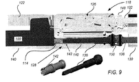
図9は、多くの実施形態による、エンドエフェクタ118へのカートリッジ100の取付け部の詳細を示す断面図である。エンドエフェクタ118は、下方ジョー120、上方ジョー122、二自由度リスト124、回転式に駆動されるクランプ機構126、及びスプリング付勢カップリング128を含む。下方ジョー120は、カートリッジ100を収容するとともに支持するように、並びにカートリッジ100をスプリング付勢カップリング128に対して位置決めするように構成される。上方ジョー122は、組織をクランプするために下方ジョー120に対して関節動作するように下方ジョー120と枢動可能に結合される。上方ジョー122は、ステープルの展開の際、ステープルを「B」形に形成するように構成されるとともにステープル開口106に対して位置決めされるステープル形成凹部を含む。
FIG. 9 is a cross-sectional view showing the details of the attachment portion of the
二自由度リスト124は、器具シャフト130に対する2つの直交軸周りのエンドエフェクタ118の関節動作のために、細長い器具シャフト130へのエンドエフェクタ118の取付けを提供する。使用されることができる適切な二自由度リストの詳細は、2010年11月12日に出願された“SURGICAL TOOL WITH A TWO DEGREE OF FREEDOM WRIST”と題する米国特許出願第12/945,748号(代理人整理番号ISRG02350/US)に開示され、この全開示が本願に参照により援用される。
The bi-degree-of-freedom list 124 provides attachment of the
回転駆動クランプ機構126は、上方と下方ジョーとの間に組織をしっかりとクランプするように、下方ジョー120に対して上方ジョー120を駆動する。クランプ機構126は、器具シャフト130の内部に配置される第1の駆動シャフト132によって回転駆動される。使用されることができる適切な回転駆動クランプ機構の詳細は、2010年11月12日に出願された“END EFFECTOR WITH REDUNDANT CLOSING MECHANISMS”と題する米国特許出願第12/945,541号(代理人整理番号ISRG02330/US)に開示され、この全開示が本願に参照により援用される。
The rotary
スプリング付勢カップリング128は、カートリッジ100の回転入力部114を延長シャフト136に回転式に結合し、この延長シャフト136は器具シャフト130の内部に配置された第2の駆動シャフト138によって駆動される。スプリング付勢カップリング128は、コイルスプリング140及びカップリング取付部品142を含む。図示された実施形態では、カップリング取付部品142は、回転入力部114及び延長シャフト136の3面の外面と相互作用する3つの突出部のスプライン受け部を用いる。スプリング付勢カップリング142は、カートリッジ100がエンドエフェクタ118に設置されるとき、発生する可能性がある3つの突出部のスプラインの角度のずれを調整する。スプリング付勢カップリング142は、角度アライメントに回転されるとき、3つの突出部のスプラインと完全に係合する。回転入力部114の回転は、カートリッジ100の駆動部材を並進させるために使用される。駆動部材の結果として生じる運動は、ステープルを展開するために及びクランプされた組織を展開されたステープルの列の中心で切るようにナイフ部材を遠位に前進させるために使用される。
The
エンドエフェクタ118は、第1のユニバーサルジョイント組立体148及び第2のユニバーサルジョイント組立体150を含む。第1のユニバーサルジョイント組立体148は、クランプ機構126を第1の駆動シャフト132に回転結合する。第2のユニバーサルジョイント組立体150は、延長シャフト136を第2の駆動シャフト138に回転結合する。第1及び第2のユニバーサルジョイント組立体148、150のそれぞれは、器具シャフト130に対するエンドエフェクタ118のピッチ及びヨーの範囲に適する角度の範囲までトルクを伝達するように構成される。使用されることができる適切なユニバーサルジョイント組立体の詳細は、2010年11月12日に出願された“DOUBLE UNIVERSAL JOINT”と題する米国特許出願第12/945,740号(代理人整理番号ISRG02340/US)に開示され、この全開示が本願に参照により援用される。
The
第1及び第2の駆動シャフト132、138は、器具シャフト130の中心線からオフセットされて(ずれて)配置され、独立して回転され得る。第1及び第2の駆動シャフト132、138を作動させるために使用されることができる適切な駆動機構の詳細は、2010年11月12日に出願された“MOTOR INTERFACE FOR PARALLEL DRIVE SHAFTS WITHIN AN INDEPENDENTLY ROTATING MEMBER”と題する米国特許出願第12/945,461号(代理人整理番号ISRG02360/US)に開示され、この全開示が本願に参照により援用される。
The first and
図10は、カートリッジ100の構成要素を示す分解斜視図である。図示された構成要素は、保持器116、66のステープル152、プリント回路組立体(PCA)スプリング154、PCA156、カートリッジボディ158、22、ステープルプッシャ160、第1の駆動部材144、第2の駆動部材145、ナイフ146、リードスクリュー134、スラストワッシャ162、リードスクリューナット164、及びカバー166を含む。カートリッジボディ158は、6列に配置された66のステープル開口106を有し、ステープル開口106の3列は長手方向スロット108の両側に配置される。保持器116は、カートリッジ100に取り外し可能に取付け可能であるとともに、カートリッジ100の使用の前にステープル152を保持するためにステープル開口106を覆う。ステープルプッシャ160は、ステープル152と相互作用するとともに、カートリッジボディ158とスライド可能に相互作用する。リードスクリュー134は、ネジ部135及びネジ部135に対して遠位端104に向かって配置される非ネジ部137を有する。リードスクリュー134のネジ部135に沿った第1の駆動部材144の運動は、第1の駆動部材144が遠位端104に向かって動くとき、ステープル152を展開するために、カートリッジボディ158に対してステープルプッシャ160を上に駆動するように、第1の駆動部材144の遠位を向く傾斜面176によるステープルプッシャ160の係合をもたらす。ナイフ146は、第1の駆動部材144から枢動可能に支持される。ナイフ146は、第2の駆動部材145の外部ギヤ歯と相互作用する外部ギヤ歯を含む。カバー166は、カートリッジボディ158に取付けられる。
FIG. 10 is an exploded perspective view showing the components of the
図11Aは、PCA156及びPCAスプリング154をさらに示す。PCAスプリング154は、カートリッジボディ158と相互作用するとともにPCA156を保持する。PCAスプリング154は、PCAスプリングフック172を含み、このPCAスプリングフック172は、PCAスプリング154を保持するように、カートリッジボディ158をつかむ。カートリッジ100がエンドエフェクタ118に取付けられるとき、エンドエフェクタ118の器具ピン174がPCA156の下にスライドするとともにPCA156を持ち上げ、したがってPCA156を器具ピン174と電気的に接続し、増大した公差の使用を可能にする。しかし、この配置は、器具ピン174がPCA156と適切に接触する限り、危機的ではない。したがって、幾つかの実施形態では、PCA156は、図示されたチップが荷重経路の外にあるように、オンにされる端部であり得る。PCA156は、カートリッジ100に結び付けられる識別、構成、及び/又は用途情報を電子的に格納するために使用されることができる。
FIG. 11A further shows
カートリッジ100は、以下の組立順序を使用して組み立てられることができる。最初に、カートリッジボディ158を「底を上にした」向きにした状態で、ステープルプッシャ160がステープル開口106に取付けられる。次に、第1の駆動部材144、第1の駆動部材144から枢動可能に支持されたナイフ146、第2の駆動部材145、スラストワッシャ162、及びリードスクリューナット164がリードスクリュー134に取付けられ、リードスクリューナット164は、リードスクリュー134の端部に面一にレーザ溶接される。結果として得られるリードスクリュー組立体は次に、第1の駆動部材144が遠位に前進するとき組織を切るとともにカートリッジボディ158の遠位端に向かうナイフ146の移動の端の近くでナイフ146をしまい込むことに合致するよう、第1の駆動部材144に対して適切な向きでナイフ146を置くために、第1の駆動部材144に対する第2の駆動部材145の適切な配置で第1の駆動部材144及び第2の駆動部材145がリードスクリュー134の近位端に位置決めされた状態でカートリッジボディ158に取付けられる。結果として得られる組立体は次に、例えば、結果として得られる組立体を潤滑剤に浸すことによって、潤滑されることができる。次に、カバー166がカートリッジボディ158に取付けられる。次に、組立体は、「上部を上にする」向きにひっくり返され、PCA156が取付けられる。次に、PCAスプリング154が、PCAスプリングフック172がかかるまでカートリッジボディ158に押し付けられる。次に、ステープル152がステープル開口106に取付けられ、保持器116がその後取付けられる。最後に、データがPCA156に導入される。
The
図12Aは、カートリッジボディ158の遠位端を示す。図12Bは、ステープルプッシャ160の1つの上面図及び斜視図を示す。図示されるように、ステープル開口106及びステープルプッシャ160は、駆動部材144がカートリッジ遠位端104に向かって並進移動されるときの駆動部材144によって駆動されることに応じたステープル開口106内での並進運動のために、ステープルプッシャ160のそれぞれがステープル開口106の1つの中に収容されるように、相補的な形状を有する。
FIG. 12A shows the distal end of the
図13Aは、第1の駆動部材144、第1の駆動部材144(図示されないピボットピン)から枢動可能に支持されたナイフ146、第2の駆動部材145を含むカートリッジ100の組立体200を示す。図13は、リードスクリュー134に結合された組立体を示す。第1の駆動部材144及び第2の駆動部材145のそれぞれは、リードスクリュー134の回転に応じたリードスクリュー134に沿った同時の並進運動のために、リードスクリュー134のネジ部135と動作可能に結合する内部ネジを含む。第1及び第2の駆動部材144、145がネジ部135に沿って並進運動するとき、第1及び第2の駆動部材144、145は、固定された相対位置を保ち、したがって第2の駆動部材145とナイフ146との間のギヤ接続を介して第1の駆動部材144に対するナイフ146の回転を妨げる。ナイフ146の関節動作の終わりの近くで、第1の駆動部材144は、リードスクリュー134の非ネジ部137の上に駆動される。その後、リードスクリュー134の継続する回転は、カートリッジボディ158に対する第1の駆動部材144のさらなる遠位の運動なしで、カートリッジボディ158に対する第2の駆動部材145の継続する遠位運動をもたらす。第1の駆動部材144に対する第2の駆動部材145の結果として得られる相対遠位運動は、ナイフ146を、例えば長手方向スロット108に、しまい込むように、第1の駆動部材144に対してナイフ146を回転させる。組立体200は、第2の駆動部材145の遠位表面202が第1の駆動部材144に対するナイフ146の回転を終わらせるために第1の駆動部材144の近位表面204に接触するように構成されることができる。したがって、ネジ部135に沿った第2の駆動部材145の継続する遠位運動は、組立体200を遠位に、例えば、カートリッジ158の遠位ガレージ112へ駆動するために使用されることができる。
FIG. 13A shows an
図示された実施形態では、いったん第1の駆動部材144が非ネジ部137上に駆動されると、リードスクリュー134に沿った第2の駆動部材145の継続する遠位運動はナイフ146をしまい込むために使用される。代替的には、第1の駆動部材144がリードスクリュー134の非ネジ部137の上に駆動された後、リードスクリュー134の回転方向が、第1の駆動部材144に対して第2の駆動部材145を近位に動かすように反転されることができ、したがって、ナイフ146を長手方向スロット108内にしまい込むように第1の駆動部材144に対してナイフ146を回転させる。
In the illustrated embodiment, once the
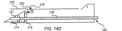
図14から14Eは、多くの実施形態による、手術器具210のナイフを関節動作させるための他のアプローチを概略的に示す。手術器具210は、ハウジング212、リードスクリュー134、第1の駆動部材214、ナイフ216、第2の駆動部材218、ナイフキックアップ機構330、及びナイフキックダウン機構222を含む。ハウジング212は、近位端224、遠位端226、近位端224と遠位端226との間に延びる上面228、近位ナイフガレージ230、遠位ナイフガレージ232、近位端224と遠位端226との間に延びる中心空洞、及び上面228と中心空洞との間に延びる長手方向スロットを含む。リードスクリュー134はネジ部135及びネジ部135に対して遠位端226に向かって配置される非ネジ部137を含む。第1及び第2の駆動部材214、218は、リードスクリュー134の回転に応じたネジ部135に沿った並進運動のために、リードスクリュー134のネジ部135と結合するように構成される内部ネジ部を有する。ナイフ216は、第1の駆動部材214から枢動可能に支持される。ナイフキックアップ機構220及びナイフキックダウン機構222は、ハウジング212に結合されるとともに、ハウジング212に対して固定位置を有する。
14-14E schematically show other approaches for articulating the knife of
図14Aは、ナイフ216が近位ガレージ230に配置されている始動形態の手術器具210を示す。ナイフ216は、第1の駆動部材214に対して非切断方向にある(すなわち、図14Bに示されるナイフの切断方向に対して回転されている)状態で示される。ナイフの非切断方向は、第1の駆動部材214及びナイフ216の組み合わせの初期長さを減らすことによってより短いハウジングの使用を可能にし得る。より短いハウジングは、よりコンパクトな手術器具210を提供し、したがって、手術器具の操作のし易さ及び/又は手術野内の可視性を高める。代替的には、ナイフ部材216は切断位置で始動することができる。
FIG. 14A shows a starting form of
図14Aに示される開始構成から、リードスクリュー134の回転は同時に、第1及び第2の駆動部材214、218をリードスクリュー134に沿って遠位に駆動する。第1の駆動部材214の初期遠位運動の間、ナイフ216は、キックアップ機構220に接触し、このキックアップ機構220は、第1の駆動部材214に対する図14Bに示された切断位置へのナイフ216の回転を生じさせる。切断位置において、第1の駆動部材214に対するナイフ216のさらなる回転は第2の駆動部材218によって妨げられる。
From the starting configuration shown in FIG. 14A, the rotation of the
図14Bに示された位置から、リードスクリュー134の継続する回転は、第1の駆動部材214が図14Cに示されるリードスクリュー134の非ネジ部137の上に駆動されるまで、リードスクリュー134に沿って第1及び第2の駆動部材214、218を遠位に同時に駆動し続ける。図14Cに示される位置から、リードスクリュー134の継続する回転は、第2の駆動部材218が図14Dに示される第1の駆動部材214に接触するところまでリードスクリュー134のネジ部135に沿って、第2の駆動部材218のみを回転させ続ける。図14Dに示される位置では、第2の駆動部材218は、もはや第1の駆動部材214に対するナイフ216の回転を妨げるように、位置しない。図14Dに示される位置から、リードスクリュー134の継続する回転は、リードスクリュー134のネジ部135に沿って第2の駆動部材218を駆動させ続け、したがってまた、リードスクリュー134の非ネジ部137に沿って第1の駆動部材214を駆動する。リードスクリュー134の非ネジ部137に沿って第1の駆動部材214を駆動することによって、ナイフ216はキックダウン機構222を接触し、したがって、ナイフ216が、図14Eに示された位置への第1及び第2の駆動部材214、218の継続する遠位の運動の間に遠位ナイフガレージ232へのしまい込みのために、長手方向スロットに回転して下げることを確実にする。
From the position shown in FIG. 14B, continued rotation of the
図15Aから15Dは、多くの実施形態による、手術器具のナイフを関節動作させるための他のアプローチを示す。ナイフ作動組立体240は、駆動部材242、ナイフ244、及び支持部材246を含む。駆動部材242は、リードスクリュー134の回転に応じたリードスクリュー134に沿った並進運動のために、リードスクリュー134に動作可能に結合するように、内部にネジ山を形成される。駆動部材242は、駆動部材242がリードスクリュー134に沿って並進運動するときステープルを展開するためのステープルプッシャと相互作用するように構成される遠位を向く傾斜面248を含む。ナイフ244は、ピボットピン(図示せず)を介して駆動部材242から枢動可能に支持される。支持部材246は、中心スロット250、遠位部252、及びガイドピン254を含む。支持部材246は、駆動部材242にスライド可能に取付けられる。支持部材246の遠位部252は、支持部材246が図15A及び15Bに示されるように駆動部材242に対して位置するとき、駆動部材242に対するナイフ244の回転を妨げる。
Figures 15A-15D show other approaches for articulating surgical instrument knives, according to many embodiments. The
ナイフ作動部材240は、ナイフ244の関節動作の開始からナイフ244の関節動作の終わりの近くまで図15A及び15Bに示された形状を保つように構成され、したがって、ナイフ244を駆動部材242に対して切る向きに保つ。例えば、支持部材246と駆動部材242との間の締りばめ及び/又は保持対策(例えば、接着剤、壊れやすい機構)が、支持部材246と駆動部材242との間の意図しない運動を防ぐために使用されることができる。
The
ナイフ244の関節動作の終わりの近くで、支持部材246は、支持部材246のさらなる遠位運動を防止するとともに駆動部材242のさらなる遠位運動を妨げないハウジングの一部に接触する。その後、リードスクリュー134の継続する回転は、リードスクリュー134に沿った駆動部材242のさらなる遠位の運動をもたらし、したがって、支持部材246と駆動部材242との間の相対運動をもたらす。相対運動は、駆動部材242に対するナイフ244の以前に妨げられていた回転を可能にするために支持部材246の遠位部252及び中心スロット250を再位置決めするように、支持部材246を再位置決めする。いったん支持部材246が、駆動部材242に対するナイフ244の以前に妨げられていた回転を可能にするために駆動部材242に対して再位置決めされると、リードスクリュー134の継続する回転は、ナイフ244がキックダウン機構256と接触するように、リードスクリュー134に沿って駆動部材242を遠位にさらに動かすために使用されることができ、このキックダウン機構256は、ナイフ244をしまい込むために、駆動部材242に対するナイフ244の回転を確実にする。
Near the end of the joint movement of the
図16は、多くの実施形態による、手術器具のナイフを関節動作させるための他のアプローチを示す。ナイフ作動組立体260は、駆動部材262、ナイフ264、遠位部材266、及びリードスクリュー134を含む。駆動部材262及び遠位部材266は、ハウジングにスライド可能に取付けられるとともにリードスクリュー134に取付けられる。駆動部材262は、内部ネジ部268を有し、この内部ネジ部268は、リードスクリュー134の回転に応じてリードスクリュー134に沿って駆動部材262を動かすように、リードスクリュー134に動作可能に結合される。遠位部材266は、リードスクリュー134に動作可能に結合されていない。代わりに、遠位部材266は、駆動部材262によってリードスクリュー134に沿って遠位に押される。遠位部材266は、遠位部材266が駆動部材262によってリードスクリュー134に沿って押されるとき、ステープルプッシャと係合するように構成される。ナイフ264は、ピボットピン272を介して駆動部材262から枢動可能に支持される。
FIG. 16 shows another approach for articulating the knife of a surgical instrument, according to many embodiments. The
組立体260は、駆動部材262が遠位部材264をリードスクリューに沿って押すとき切断位置にナイフ264を向けるように及び駆動部材262が遠位部材264に対して近位に動かされるときナイフ264をしまい込むように構成される。遠位部材264は、駆動部材262に対してナイフ264を回転で向きを合わせるようにナイフ264と相互作用するインターフェース機構274を含む。駆動部材262が遠位部材264を押しているとき、インターフェース機構274は、ナイフ264を切断位置に向けるように及びピボットピン272周りのナイフ264の回転を妨げるように位置決めされ、したがって、ナイフ264を切断位置に保つ。インターフェース機構274はまた、駆動部材262が遠位部材264に対して近位に動かされるとき、駆動部材262に対するナイフ264の回転を含み、したがってナイフ264をしまい込む。動作において、リードスクリュー134は、最初に駆動部材262を遠位にリードスクリュー134に沿って進めるように回転され、それによって、ステープルを展開するように及びナイフ264を切断位置に保つように遠位部材262をリードスクリュー134に沿って押す。組立体260の遠位運動の終わりにおいて、リードスクリュー134の回転の方向は、遠位部材266に対して駆動部材262を近位に後退させるように反転され、それによって、ナイフ264をインターフェース機構272とナイフ264との間の相互作用を介してしまい込まれた位置に下へ回転させる。
The
図17は、多くの実施形態による、手術器具のナイフを関節動作させるための他のアプローチを示す。ナイフ作動組立体280は、駆動部材282、ナイフ284、ナイフスレッド286、及びリードスクリュー134を含む。駆動部材282及びナイフスレッド286は、ハウジングにスライド可能に取付けられる。駆動部材282は、リードスクリュー134の回転に応じてリードスクリュー134に沿って駆動部材282を動かすようにリードスクリュー134に動作可能に結合される内部ネジ部を含む。ナイフスレッド286は、駆動部材282とナイフスレッド286の駆動機構288との間の接触を介して駆動部材282によって遠位に駆動可能である。ナイフ284は、ピボットピン290を介してナイフスレッド286から枢動可能に支持される。ナイフスレッド286に対するナイフ284の角度の向きは、駆動部材282のインターフェース機構292によってナイフスレッド286に対する駆動部材282の位置に結合され、このインターフェース機構292は、ナイフスレッド286に対するナイフ284の角度の向きを制御するためにナイフ284と相互作用する。駆動部材282は、駆動部材282がリードスクリュー134に沿って遠位に動くとき、ステープルプッシャと係合するように構成される遠位を向く傾斜面294を含む。
FIG. 17 shows another approach for articulating the knife of a surgical instrument, according to many embodiments. The
組立体280は、駆動部材282がナイフスレッド286をリードスクリューに沿って押すとき切断位置にナイフ284を向けるように及び駆動部材282がナイフスレッド286に対して近位に動かされるときナイフ284をしまい込むように構成される。動作において、リードスクリュー134は、最初に駆動部材282を遠位にリードスクリュー134に沿って進めるように回転され、それによって、ナイフスレッド286を遠位方向に押すとともにナイフ284を切断位置に角度に関して向ける。組立体280の遠位運動の終わりにおいて、リードスクリュー134の回転の方向は、ナイフスレッド286に対して駆動部材282を近位に後退させるように反転され、それによって、ナイフ284をインターフェース機構292とナイフ284との間の相互作用を介してしまい込まれた位置に下へ回転させる。
The
組み合わせ及び/又は変更
ここに開示される手術器具、組立体、及びカートリッジは、任意の適切な方法で、変更される及び/又は組み合わされることができる。例えば、ここに記載されるカートリッジ100は、ここに記載される手術器具210で実施されるナイフ関節動作アプローチを用いるように、ここに記載されるナイフ作動組立体240を用いるように、ここに記載されるナイフ作動組立体260を用いるように、又はここに記載されるナイフ作動組立体280を用いるように、変更されることができる。同様に、ここに開示される手術器具210は、ここに記載されるナイフ作動組立体200を用いるように、ここに記載されるようなナイフ作動組立体240を用いるように、ここに記載されるようなナイフ作動組立体260を用いるように、又はここに記載されるようなナイフ作動組立体280を用いるように、変更されることができる。そして、ここに開示される、又は前述の変更から生じる手術器具、組立体、及びカートリッジは、カートリッジ100等取外し可能に取付け可能なカートリッジに統合されることができ、手術器具のエンドエフェクタに取り外し可能に取付け可能であることなしに手術器具に直接統合されることができる。
Combinations and / or Modifications The surgical instruments, assemblies, and cartridges disclosed herein can be modified and / or combined in any suitable manner. For example, the
ナイフ関節動作方法
図18は、多くの実施形態による、手術器具にナイフを関節動作させる方法300の動作を示す。任意の適切な手術器具(例えば、ステープル及び切断手術器具、電気手術血管シール装置)が、方法300を実施するために使用されることができる。例えば、ここに記載されるリニアステープル及び切断手術器具、カートリッジ、及び関連する組立体が方法300を実施するために使用されることができる。
Knife Joint Operation Method FIG. 18 shows the operation of a
動作302において、ナイフは第1の部材から枢動可能に支持される。ナイフは、ナイフがハウジング遠位端に向かって動かされるとき、切るように構成される。動作304において、第1の部材に対するナイフの回転は、第1及び第2の部材を遠位端に向かって同じ速度で動かす間、第2の部材によって妨げられる。動作306において、第1及び第2の部材を遠位端に向かって同じ速度で動かした後、第2の部材は、ナイフの妨げられた回転を可能にすること又はナイフの妨げられた回転を引き起こすことの少なくとも一方を達成するように、第1の部材に対して動かされる。
In motion 302, the knife is pivotally supported by the first member. The knife is configured to cut as the knife is moved towards the distal end of the housing. In
図19は、多くの実施形態による、方法300で達成されることができるオプションの動作を示す。オプション動作308において、リードスクリューは、第1及び第2の駆動部材をリードスクリューに沿って遠位に動かすように回転される。オプション動作310において、ネジ部及び非ネジ部を有するリードスクリューは、第1の部材に対して第2の部材を動かすように回転される。オプション動作312において、ナイフ部材は、第1と第2の部材との間の相対運動に応じて第1の部材に対して回転される。オプション動作314において、第1及び第2の部材の一方は、遠位端に向かって動かされる一方、第1及び第2の部材の他方は、ナイフの回転を妨げないように第2の部材を再位置決めするために遠位端に向かって動くことが防がれる。オプション動作316において、ナイフは、ナイフの切断刃を手術器具のハウジングの上面の下にしまい込むようにナイフを回転させるキックダウン機構と係合される。オプション動作318において、ナイフは、ナイフの切断刃を手術器具のハウジングの上面の下にしまい込むようにナイフを回転させる第2の部材と結合されるキックダウン機構と係合される。オプション動作320において、ナイフは、第1及び第2の部材の遠位端に向かう同じ速度での運動中、ナイフを切断位置に回転させるためのキックアップ機構と係合される。オプション動作322において、ステープルは、第1及び第2の部材の遠位端に向かう同じ速度での運動中に展開される。
FIG. 19 shows the optional behavior that can be achieved by
ここに開示される方法は、任意の適切な応用において用いられることができる。例えば、ここに開示される方法は、観血又は低侵襲(1つの又は複数ポートの)手術のために、手動又は動力式、ハンドヘルド又はロボット式、直接制御される又は遠隔操作される、手術器具に用いられることができる。 The methods disclosed herein can be used in any suitable application. For example, the methods disclosed herein are manual or powered, handheld or robotic, directly controlled or remotely controlled surgical instruments for open or minimally invasive (one or more ports) surgery. Can be used for.
他の変形形態は、本発明の精神の範囲内にある。したがって、本発明は様々な変形形態及び代替構成を受け入れ得るが、そのいくつかの実施形態を図に示し、詳細に説明した。しかし、本発明を開示された特定の形態に限定する意図はなく、それどころか、意図は、添付の特許請求の範囲に定められるような、本発明の精神及び範囲に入るあらゆる変更、代替構成及び均等物をカバーすることにあることが理解されるべきである。 Other variants are within the spirit of the invention. Accordingly, the present invention may accept a variety of variations and alternative configurations, some of which are illustrated and described in detail. However, there is no intention to limit the invention to the particular form disclosed, and on the contrary, the intent is any modification, alternative configuration and equality that falls within the spirit and scope of the invention, as set forth in the appended claims. It should be understood that it is in covering things.
用語「力」は、特に明記されない限り又は文脈によって明確に否定されない限り、(特に以下の請求項の文脈において)力及びトルクの両方を包含するものとして解釈されるべきである。本発明を記載する文脈における用語1つの(“a”及び“an”)」及び「その(“the”)」の使用は、特に明記されない限り又は文脈によって明確に否定されない限り、(特に以下の請求項の文脈において)単数及び複数の両方をカバーするように解釈されるべきである。用語「有する(“comprising”)」、「有する(“having”)」、含む(“including”」、及び「含有する(“containing”」は、特に断りのない限り、制限のない語(open-ended term)(即ち「含むが、限定されないこと」を意味する)と解釈されるべきである。用語「接続される」は、何かが介在する場合であっても、部分的に又は完全に、その中に含まれる、取付けられる、又は一緒に結合されるものと解釈されるべきである。本明細書中に列挙される値の範囲は、特に明記されない限り、範囲内に入る別々の各値を個別に参照する簡便な表記法として役立つように意図しているにすぎず、別々の各値は明細書中に個別に列記されているかのように組み込まれている。本明細書に記載される全ての方法は、特に明記されない限り又は文脈によって明確に否定されない限り、任意の適切な順序で実行されることができる。明細書中に与えられている任意の若しくはすべての例、又は例示的な語(例えば、「等」の使用は、本発明の実施形態をより良く照らし出すことを意図しているにすぎず、特に特許請求の範囲に記載されない限り本発明の範囲に限定を加えるものではない。本明細書中の語は、本発明の実施に必須であるとして特許請求の範囲に記載されてない構成要素を示すものと解釈されるべきでない。 The term "force" should be construed to include both force and torque (especially in the context of the following claims) unless otherwise specified or explicitly denied by the context. The use of one of the terms (“a” and “an”) ”and“ (“the”) ”in the context of describing the invention is not specified unless otherwise specified or explicitly denied by the context (particularly the following: It should be construed to cover both singular and plural (in the context of the claims). The terms "comprising", "having", "including", and "containing" are unlimited terms (open-) unless otherwise noted. It should be interpreted as an ended term) (ie, meaning "including, but not limited to"). The term "connected" is partially or completely, even if something intervenes. , Included, attached, or combined together. The range of values listed herein is each separate within the range, unless otherwise specified. It is only intended to serve as a convenient notation for referencing values individually, and each separate value is incorporated herein as if it were listed individually. All methods may be performed in any suitable order unless otherwise specified or expressly denied by the context. Any or all examples, or illustrations given herein. The use of such terms (eg, "etc.") is only intended to better illuminate embodiments of the invention and limits the scope of the invention unless specifically stated in the scope of the patent claim. Nothing. The terms herein should not be construed as referring to components that are not stated in the scope of the patent claim as essential to the practice of the present invention.
本発明を実施するために発明者に知られているベストモードを含む、本発明の好適な実施形態がここに記載されている。これらの好適実施例の変更は、前述の記載を読めば、当業者に明らかになり得る。発明者は、熟練した技術者がこのような変更を適切に利用することを期待し、発明者は、本発明が特にここに記載されるものと異なる方法で実施されることを意図する。従って、本発明は適用される法律で認められるように、添付の請求項に記載された主題のあらゆる変更及び均等物を含む。さらに、あらゆる可能な変更における上述の要素の任意の組み合わせは、特に明記されない限り又は文脈によって明確に否定されない限り、本発明によって包含される。 Suitable embodiments of the present invention are described herein, including the best modes known to the inventor for carrying out the present invention. Changes to these preferred embodiments may be apparent to those skilled in the art by reading the above description. The inventor expects a skilled technician to take advantage of such changes, and the inventor intends the invention to be carried out in a manner different from that specifically described herein. Accordingly, the present invention includes all modifications and equivalents of the subject matter set forth in the appended claims, as permitted by applicable law. Moreover, any combination of the above elements in any possible modification is included by the present invention unless otherwise specified or expressly denied by the context.
本明細書に引用した刊行物、特許出願公報、及び特許公報を含む全ての参考文献は、各参考文献が参照により援用されるように個別に特に示されるとともに完全に記載されているのと同程度に、参照によって援用される。 All references, including publications, patent application gazettes, and patent gazettes cited herein, are individually specifically indicated and fully described so that each reference is incorporated by reference. To a degree, incorporated by reference.
Claims (18)
前記シャフト遠位端に結合されるエンドエフェクタであって、前記エンドエフェクタは、第1の端部及び第2の端部を有し、前記エンドエフェクタは:
前記エンドエフェクタの前記第2の端部に向かって移動可能な第1の部材と;
前記第1の部材に枢動可能に結合されるナイフと;
第2の部材であって、(a)前記エンドエフェクタの前記第2の端部に向かう前記第1の部材及び前記第2の部材の同時の運動の間に前記第1の部材に対する前記ナイフの回転を妨げるように、並びに(b)前記ナイフをしまい込むための前記ナイフの回転を許容するため又は前記ナイフをしまい込むための前記ナイフの回転を引き起こすために前記第1の部材に対して動くように、前記第1の部材及び前記第2の部材の前記同時の運動に続いて前記エンドエフェクタの前記第2の端部に向かって動き続けるように構成される、第2の部材と;
を含む、エンドエフェクタ;
を有する、
手術器具。 An elongated shaft having a distal end to the shaft: and an end effector coupled to the distal end of the shaft, wherein the end effector has a first end and a second end, and the end effector is:
With a first member that is movable towards the second end of the end effector;
With a knife pivotally coupled to the first member;
A second member of the knife with respect to the first member during the simultaneous movement of (a) the first member and the second member towards the second end of the end effector. so as to prevent rotation movement relative to, and (b) the first member to cause rotation of the knives for stowing or the knife to permit rotation of said knife for stowing the knife as described above, with the first member and configured to continue to move toward the second end of the end effector following the simultaneous movement of the second member, the second member;
End effectors, including;
Have,
Surgical instruments.
請求項1に記載の手術器具。 The end effector is a lead screw that is operably coupled to at least one of the first member or the second member, and the connected member is connected to the lead screw in response to rotation of the lead screw. Drive along at least part of, including lead screw,
The surgical instrument according to claim 1.
請求項2に記載の手術器具。 The lead screw has a threaded portion and a non-threaded portion located distal to the threaded portion, and both the first and second members include the second member together with the first member. When moving at the same speed towards the second end of the end effector, it is driven along the lead screw to generate a relative motion between the first and second member. One of the first and second members interacts with the unthreaded portion, and the other of the first and second members interacts with the threaded portion.
The surgical instrument according to claim 2.
請求項1に記載の手術器具。 The second member moves toward the second end of the end effector when the second member moves relative to the first member.
The surgical instrument according to claim 1.
請求項1に記載の手術器具。 The first member moves toward the first end of the end effector when the second member moves relative to the first member.
The surgical instrument according to claim 1.
請求項1に記載の手術器具。 The knife engages with gear teeth coupled to the second member so that the relative movement between the first and second member causes rotation of the knife with respect to the first member. Including teeth,
The surgical instrument according to claim 1.
請求項1に記載の手術器具。 The second member is slidably attached to the first member so as to move along the first distance together with the first member, and the first and second members are slidably attached to the first distance. The second member does not move toward the second end of the end effector during the movement of the first member towards the second end of the end effector.
The surgical instrument according to claim 1.
請求項1に記載の手術器具。 The end effector has a kick-up mechanism configured to rotate the knife to a cutting position during the movement of the knife towards the second end of the end effector.
The surgical instrument according to claim 1.
請求項1に記載の手術器具。 The end effector includes a plurality of staple openings and a plurality of staples arranged in the staple openings, each of which is the first and second member towards the second end of the end effector. Unfolded during the exercise of
The surgical instrument according to claim 1.
前記カートリッジの前記第2の端部に向かって移動可能な第1の部材と;
前記第1の部材に枢動可能に結合されるナイフと;
第2の部材であって、(a)前記カートリッジの前記第2の端部に向かう前記第1の部材及び前記第2の部材の同時の運動の間に前記第1の部材に対する前記ナイフの回転を妨げるように、並びに(b)前記ナイフをしまい込むための前記ナイフの回転を許容するため又は前記ナイフをしまい込むための前記ナイフの回転を引き起こすために前記第1の部材に対して動くように、前記第1の部材及び前記第2の部材の前記同時の運動に続いて前記カートリッジの前記第2の端部に向かって動き続けるように構成される、第2の部材と;
を有する、
カートリッジ。 A removable and attachable cartridge for a surgical instrument, said cartridge having a first end and a second end, said cartridge being:
With a first member movable towards the second end of the cartridge;
With a knife pivotally coupled to the first member;
A second member, (a) rotation of the knife with respect to the first member during simultaneous movement of the first member and the second member towards the second end of the cartridge. so as to prevent, as well as (b) to move relative to the first member to cause rotation of the knives for stowing or the knife to permit rotation of said knife for stowing the knife to, said first member and configured to continue to move toward the second end of the second of said cartridge said Following simultaneous movement of the member, the second member;
Have,
cartridge.
請求項10に記載のカートリッジ。 A reed screw operably coupled to at least one of the first member or the second member, the coupled member being attached to at least a part of the reed screw in response to rotation of the reed screw. Drive along, with more reed screws,
The cartridge according to claim 10.
請求項11に記載のカートリッジ。 The lead screw has a threaded portion and a non-threaded portion located distal to the threaded portion, and in both the first and second members, the second member is combined with the first member. When moving at the same speed towards the second end of the cartridge, the first is driven along the lead screw to generate a relative motion between the first and second member. One of the first and second members interacts with the non-threaded portion and the other of the first and second members interacts with the threaded portion.
The cartridge according to claim 11.
請求項10に記載のカートリッジ。 The second member moves toward the second end of the cartridge when the second member moves relative to the first member.
The cartridge according to claim 10.
請求項10に記載のカートリッジ。 The first member moves toward the first end of the cartridge when the second member moves relative to the first member.
The cartridge according to claim 10.
請求項10に記載のカートリッジ。 The knife is a gear that meshes with a gear tooth coupled to the second member such that the relative movement between the first and second member causes rotation of the knife with respect to the first member. Including teeth,
The cartridge according to claim 10.
請求項10に記載のカートリッジ。 The second member is slidably attached to the first member so as to move along the first distance together with the first member, and the first and second members are at the first distance. After moving, the second member does not move towards the second end of the cartridge during the movement of the first member towards the second end of the cartridge.
The cartridge according to claim 10.
請求項10に記載のカートリッジ。 Further comprising a kick-up mechanism configured to rotate the knife to a cutting position during the movement of the knife towards the second end of the cartridge.
The cartridge according to claim 10.
請求項10に記載のカートリッジ。 It further has a plurality of staple openings and a plurality of staples arranged in the staple openings, each of which is during the movement of the first and second members towards the second end of the cartridge. Be expanded,
The cartridge according to claim 10.
Applications Claiming Priority (2)
| Application Number | Priority Date | Filing Date | Title |
|---|---|---|---|
| US201161560225P | 2011-11-15 | 2011-11-15 | |
| US61/560,225 | 2011-11-15 |
Related Parent Applications (1)
| Application Number | Title | Priority Date | Filing Date |
|---|---|---|---|
| JP2017145063A Division JP6442572B2 (en) | 2011-11-15 | 2017-07-27 | Surgical instrument with a knife blade |
Publications (3)
| Publication Number | Publication Date |
|---|---|
| JP2019048153A JP2019048153A (en) | 2019-03-28 |
| JP2019048153A5 JP2019048153A5 (en) | 2020-03-12 |
| JP6778246B2 true JP6778246B2 (en) | 2020-10-28 |
Family
ID=48281330
Family Applications (3)
| Application Number | Title | Priority Date | Filing Date |
|---|---|---|---|
| JP2014542324A Active JP6230541B2 (en) | 2011-11-15 | 2012-10-26 | Surgical instrument with a knife blade |
| JP2017145063A Active JP6442572B2 (en) | 2011-11-15 | 2017-07-27 | Surgical instrument with a knife blade |
| JP2018219994A Active JP6778246B2 (en) | 2011-11-15 | 2018-11-26 | Surgical instrument with a knife blade that can be stowed away |
Family Applications Before (2)
| Application Number | Title | Priority Date | Filing Date |
|---|---|---|---|
| JP2014542324A Active JP6230541B2 (en) | 2011-11-15 | 2012-10-26 | Surgical instrument with a knife blade |
| JP2017145063A Active JP6442572B2 (en) | 2011-11-15 | 2017-07-27 | Surgical instrument with a knife blade |
Country Status (6)
| Country | Link |
|---|---|
| US (4) | US8991678B2 (en) |
| EP (2) | EP2779921B1 (en) |
| JP (3) | JP6230541B2 (en) |
| KR (3) | KR102111471B1 (en) |
| CN (3) | CN111281457B (en) |
| WO (1) | WO2013074272A2 (en) |
Families Citing this family (778)
| Publication number | Priority date | Publication date | Assignee | Title |
|---|---|---|---|---|
| US11134978B2 (en) | 2016-01-15 | 2021-10-05 | Cilag Gmbh International | Modular battery powered handheld surgical instrument with self-diagnosing control switches for reusable handle assembly |
| US11229472B2 (en) | 2001-06-12 | 2022-01-25 | Cilag Gmbh International | Modular battery powered handheld surgical instrument with multiple magnetic position sensors |
| US9060770B2 (en) | 2003-05-20 | 2015-06-23 | Ethicon Endo-Surgery, Inc. | Robotically-driven surgical instrument with E-beam driver |
| US20070084897A1 (en) | 2003-05-20 | 2007-04-19 | Shelton Frederick E Iv | Articulating surgical stapling instrument incorporating a two-piece e-beam firing mechanism |
| US8182501B2 (en) | 2004-02-27 | 2012-05-22 | Ethicon Endo-Surgery, Inc. | Ultrasonic surgical shears and method for sealing a blood vessel using same |
| US8215531B2 (en) | 2004-07-28 | 2012-07-10 | Ethicon Endo-Surgery, Inc. | Surgical stapling instrument having a medical substance dispenser |
| US11896225B2 (en) | 2004-07-28 | 2024-02-13 | Cilag Gmbh International | Staple cartridge comprising a pan |
| PL1802245T3 (en) | 2004-10-08 | 2017-01-31 | Ethicon Endosurgery Llc | Ultrasonic surgical instrument |
| US10159482B2 (en) | 2005-08-31 | 2018-12-25 | Ethicon Llc | Fastener cartridge assembly comprising a fixed anvil and different staple heights |
| US11484312B2 (en) | 2005-08-31 | 2022-11-01 | Cilag Gmbh International | Staple cartridge comprising a staple driver arrangement |
| US11246590B2 (en) | 2005-08-31 | 2022-02-15 | Cilag Gmbh International | Staple cartridge including staple drivers having different unfired heights |
| US8365976B2 (en) | 2006-09-29 | 2013-02-05 | Ethicon Endo-Surgery, Inc. | Surgical staples having dissolvable, bioabsorbable or biofragmentable portions and stapling instruments for deploying the same |
| US7934630B2 (en) | 2005-08-31 | 2011-05-03 | Ethicon Endo-Surgery, Inc. | Staple cartridges for forming staples having differing formed staple heights |
| US7669746B2 (en) | 2005-08-31 | 2010-03-02 | Ethicon Endo-Surgery, Inc. | Staple cartridges for forming staples having differing formed staple heights |
| US9237891B2 (en) | 2005-08-31 | 2016-01-19 | Ethicon Endo-Surgery, Inc. | Robotically-controlled surgical stapling devices that produce formed staples having different lengths |
| US7673781B2 (en) | 2005-08-31 | 2010-03-09 | Ethicon Endo-Surgery, Inc. | Surgical stapling device with staple driver that supports multiple wire diameter staples |
| US20070191713A1 (en) | 2005-10-14 | 2007-08-16 | Eichmann Stephen E | Ultrasonic device for cutting and coagulating |
| US20070106317A1 (en) | 2005-11-09 | 2007-05-10 | Shelton Frederick E Iv | Hydraulically and electrically actuated articulation joints for surgical instruments |
| US7621930B2 (en) | 2006-01-20 | 2009-11-24 | Ethicon Endo-Surgery, Inc. | Ultrasound medical instrument having a medical ultrasonic blade |
| US7753904B2 (en) | 2006-01-31 | 2010-07-13 | Ethicon Endo-Surgery, Inc. | Endoscopic surgical instrument with a handle that can articulate with respect to the shaft |
| US9861359B2 (en) | 2006-01-31 | 2018-01-09 | Ethicon Llc | Powered surgical instruments with firing system lockout arrangements |
| US20110006101A1 (en) | 2009-02-06 | 2011-01-13 | EthiconEndo-Surgery, Inc. | Motor driven surgical fastener device with cutting member lockout arrangements |
| US11224427B2 (en) | 2006-01-31 | 2022-01-18 | Cilag Gmbh International | Surgical stapling system including a console and retraction assembly |
| US8820603B2 (en) | 2006-01-31 | 2014-09-02 | Ethicon Endo-Surgery, Inc. | Accessing data stored in a memory of a surgical instrument |
| US20110290856A1 (en) | 2006-01-31 | 2011-12-01 | Ethicon Endo-Surgery, Inc. | Robotically-controlled surgical instrument with force-feedback capabilities |
| US8708213B2 (en) | 2006-01-31 | 2014-04-29 | Ethicon Endo-Surgery, Inc. | Surgical instrument having a feedback system |
| US20110024477A1 (en) | 2009-02-06 | 2011-02-03 | Hall Steven G | Driven Surgical Stapler Improvements |
| US11793518B2 (en) | 2006-01-31 | 2023-10-24 | Cilag Gmbh International | Powered surgical instruments with firing system lockout arrangements |
| US20120292367A1 (en) | 2006-01-31 | 2012-11-22 | Ethicon Endo-Surgery, Inc. | Robotically-controlled end effector |
| US7845537B2 (en) | 2006-01-31 | 2010-12-07 | Ethicon Endo-Surgery, Inc. | Surgical instrument having recording capabilities |
| US8186555B2 (en) | 2006-01-31 | 2012-05-29 | Ethicon Endo-Surgery, Inc. | Motor-driven surgical cutting and fastening instrument with mechanical closure system |
| US11278279B2 (en) | 2006-01-31 | 2022-03-22 | Cilag Gmbh International | Surgical instrument assembly |
| US8236010B2 (en) | 2006-03-23 | 2012-08-07 | Ethicon Endo-Surgery, Inc. | Surgical fastener and cutter with mimicking end effector |
| US8992422B2 (en) | 2006-03-23 | 2015-03-31 | Ethicon Endo-Surgery, Inc. | Robotically-controlled endoscopic accessory channel |
| US8322455B2 (en) | 2006-06-27 | 2012-12-04 | Ethicon Endo-Surgery, Inc. | Manually driven surgical cutting and fastening instrument |
| US10130359B2 (en) | 2006-09-29 | 2018-11-20 | Ethicon Llc | Method for forming a staple |
| US10568652B2 (en) | 2006-09-29 | 2020-02-25 | Ethicon Llc | Surgical staples having attached drivers of different heights and stapling instruments for deploying the same |
| US8652120B2 (en) | 2007-01-10 | 2014-02-18 | Ethicon Endo-Surgery, Inc. | Surgical instrument with wireless communication between control unit and sensor transponders |
| US8684253B2 (en) | 2007-01-10 | 2014-04-01 | Ethicon Endo-Surgery, Inc. | Surgical instrument with wireless communication between a control unit of a robotic system and remote sensor |
| US11291441B2 (en) | 2007-01-10 | 2022-04-05 | Cilag Gmbh International | Surgical instrument with wireless communication between control unit and remote sensor |
| US11039836B2 (en) | 2007-01-11 | 2021-06-22 | Cilag Gmbh International | Staple cartridge for use with a surgical stapling instrument |
| US20080169332A1 (en) | 2007-01-11 | 2008-07-17 | Shelton Frederick E | Surgical stapling device with a curved cutting member |
| US8727197B2 (en) | 2007-03-15 | 2014-05-20 | Ethicon Endo-Surgery, Inc. | Staple cartridge cavity configuration with cooperative surgical staple |
| US20080234709A1 (en) | 2007-03-22 | 2008-09-25 | Houser Kevin L | Ultrasonic surgical instrument and cartilage and bone shaping blades therefor |
| US8226675B2 (en) | 2007-03-22 | 2012-07-24 | Ethicon Endo-Surgery, Inc. | Surgical instruments |
| US8911460B2 (en) | 2007-03-22 | 2014-12-16 | Ethicon Endo-Surgery, Inc. | Ultrasonic surgical instruments |
| US8057498B2 (en) | 2007-11-30 | 2011-11-15 | Ethicon Endo-Surgery, Inc. | Ultrasonic surgical instrument blades |
| US8142461B2 (en) | 2007-03-22 | 2012-03-27 | Ethicon Endo-Surgery, Inc. | Surgical instruments |
| US8893946B2 (en) | 2007-03-28 | 2014-11-25 | Ethicon Endo-Surgery, Inc. | Laparoscopic tissue thickness and clamp load measuring devices |
| US8931682B2 (en) | 2007-06-04 | 2015-01-13 | Ethicon Endo-Surgery, Inc. | Robotically-controlled shaft based rotary drive systems for surgical instruments |
| US11672531B2 (en) | 2007-06-04 | 2023-06-13 | Cilag Gmbh International | Rotary drive systems for surgical instruments |
| US7753245B2 (en) | 2007-06-22 | 2010-07-13 | Ethicon Endo-Surgery, Inc. | Surgical stapling instruments |
| US8308040B2 (en) | 2007-06-22 | 2012-11-13 | Ethicon Endo-Surgery, Inc. | Surgical stapling instrument with an articulatable end effector |
| US11849941B2 (en) | 2007-06-29 | 2023-12-26 | Cilag Gmbh International | Staple cartridge having staple cavities extending at a transverse angle relative to a longitudinal cartridge axis |
| US8523889B2 (en) | 2007-07-27 | 2013-09-03 | Ethicon Endo-Surgery, Inc. | Ultrasonic end effectors with increased active length |
| US8882791B2 (en) | 2007-07-27 | 2014-11-11 | Ethicon Endo-Surgery, Inc. | Ultrasonic surgical instruments |
| US8808319B2 (en) | 2007-07-27 | 2014-08-19 | Ethicon Endo-Surgery, Inc. | Surgical instruments |
| US9044261B2 (en) | 2007-07-31 | 2015-06-02 | Ethicon Endo-Surgery, Inc. | Temperature controlled ultrasonic surgical instruments |
| US8430898B2 (en) | 2007-07-31 | 2013-04-30 | Ethicon Endo-Surgery, Inc. | Ultrasonic surgical instruments |
| US8512365B2 (en) | 2007-07-31 | 2013-08-20 | Ethicon Endo-Surgery, Inc. | Surgical instruments |
| EP2796102B1 (en) | 2007-10-05 | 2018-03-14 | Ethicon LLC | Ergonomic surgical instruments |
| US10010339B2 (en) | 2007-11-30 | 2018-07-03 | Ethicon Llc | Ultrasonic surgical blades |
| US8561870B2 (en) | 2008-02-13 | 2013-10-22 | Ethicon Endo-Surgery, Inc. | Surgical stapling instrument |
| US9179912B2 (en) | 2008-02-14 | 2015-11-10 | Ethicon Endo-Surgery, Inc. | Robotically-controlled motorized surgical cutting and fastening instrument |
| US7866527B2 (en) | 2008-02-14 | 2011-01-11 | Ethicon Endo-Surgery, Inc. | Surgical stapling apparatus with interlockable firing system |
| US7819298B2 (en) | 2008-02-14 | 2010-10-26 | Ethicon Endo-Surgery, Inc. | Surgical stapling apparatus with control features operable with one hand |
| BRPI0901282A2 (en) | 2008-02-14 | 2009-11-17 | Ethicon Endo Surgery Inc | surgical cutting and fixation instrument with rf electrodes |
| US8636736B2 (en) | 2008-02-14 | 2014-01-28 | Ethicon Endo-Surgery, Inc. | Motorized surgical cutting and fastening instrument |
| US8758391B2 (en) | 2008-02-14 | 2014-06-24 | Ethicon Endo-Surgery, Inc. | Interchangeable tools for surgical instruments |
| US8573465B2 (en) | 2008-02-14 | 2013-11-05 | Ethicon Endo-Surgery, Inc. | Robotically-controlled surgical end effector system with rotary actuated closure systems |
| US8657174B2 (en) | 2008-02-14 | 2014-02-25 | Ethicon Endo-Surgery, Inc. | Motorized surgical cutting and fastening instrument having handle based power source |
| US9585657B2 (en) | 2008-02-15 | 2017-03-07 | Ethicon Endo-Surgery, Llc | Actuator for releasing a layer of material from a surgical end effector |
| US11272927B2 (en) | 2008-02-15 | 2022-03-15 | Cilag Gmbh International | Layer arrangements for surgical staple cartridges |
| US9089360B2 (en) | 2008-08-06 | 2015-07-28 | Ethicon Endo-Surgery, Inc. | Devices and techniques for cutting and coagulating tissue |
| US7857186B2 (en) | 2008-09-19 | 2010-12-28 | Ethicon Endo-Surgery, Inc. | Surgical stapler having an intermediate closing position |
| PL3476312T3 (en) | 2008-09-19 | 2024-03-11 | Ethicon Llc | Surgical stapler with apparatus for adjusting staple height |
| US9005230B2 (en) | 2008-09-23 | 2015-04-14 | Ethicon Endo-Surgery, Inc. | Motorized surgical instrument |
| US9050083B2 (en) | 2008-09-23 | 2015-06-09 | Ethicon Endo-Surgery, Inc. | Motorized surgical instrument |
| US8210411B2 (en) | 2008-09-23 | 2012-07-03 | Ethicon Endo-Surgery, Inc. | Motor-driven surgical cutting instrument |
| US11648005B2 (en) | 2008-09-23 | 2023-05-16 | Cilag Gmbh International | Robotically-controlled motorized surgical instrument with an end effector |
| US9386983B2 (en) | 2008-09-23 | 2016-07-12 | Ethicon Endo-Surgery, Llc | Robotically-controlled motorized surgical instrument |
| US8608045B2 (en) | 2008-10-10 | 2013-12-17 | Ethicon Endo-Sugery, Inc. | Powered surgical cutting and stapling apparatus with manually retractable firing system |
| US8517239B2 (en) | 2009-02-05 | 2013-08-27 | Ethicon Endo-Surgery, Inc. | Surgical stapling instrument comprising a magnetic element driver |
| BRPI1008667A2 (en) | 2009-02-06 | 2016-03-08 | Ethicom Endo Surgery Inc | improvement of the operated surgical stapler |
| US8444036B2 (en) | 2009-02-06 | 2013-05-21 | Ethicon Endo-Surgery, Inc. | Motor driven surgical fastener device with mechanisms for adjusting a tissue gap within the end effector |
| US9700339B2 (en) | 2009-05-20 | 2017-07-11 | Ethicon Endo-Surgery, Inc. | Coupling arrangements and methods for attaching tools to ultrasonic surgical instruments |
| US8650728B2 (en) | 2009-06-24 | 2014-02-18 | Ethicon Endo-Surgery, Inc. | Method of assembling a transducer for a surgical instrument |
| US8663220B2 (en) | 2009-07-15 | 2014-03-04 | Ethicon Endo-Surgery, Inc. | Ultrasonic surgical instruments |
| USRE47996E1 (en) | 2009-10-09 | 2020-05-19 | Ethicon Llc | Surgical generator for ultrasonic and electrosurgical devices |
| US11090104B2 (en) | 2009-10-09 | 2021-08-17 | Cilag Gmbh International | Surgical generator for ultrasonic and electrosurgical devices |
| US10441345B2 (en) | 2009-10-09 | 2019-10-15 | Ethicon Llc | Surgical generator for ultrasonic and electrosurgical devices |
| US8951248B2 (en) | 2009-10-09 | 2015-02-10 | Ethicon Endo-Surgery, Inc. | Surgical generator for ultrasonic and electrosurgical devices |
| US9168054B2 (en) | 2009-10-09 | 2015-10-27 | Ethicon Endo-Surgery, Inc. | Surgical generator for ultrasonic and electrosurgical devices |
| US8851354B2 (en) | 2009-12-24 | 2014-10-07 | Ethicon Endo-Surgery, Inc. | Surgical cutting instrument that analyzes tissue thickness |
| US8220688B2 (en) | 2009-12-24 | 2012-07-17 | Ethicon Endo-Surgery, Inc. | Motor-driven surgical cutting instrument with electric actuator directional control assembly |
| US9259234B2 (en) | 2010-02-11 | 2016-02-16 | Ethicon Endo-Surgery, Llc | Ultrasonic surgical instruments with rotatable blade and hollow sheath arrangements |
| US8579928B2 (en) | 2010-02-11 | 2013-11-12 | Ethicon Endo-Surgery, Inc. | Outer sheath and blade arrangements for ultrasonic surgical instruments |
| US8961547B2 (en) | 2010-02-11 | 2015-02-24 | Ethicon Endo-Surgery, Inc. | Ultrasonic surgical instruments with moving cutting implement |
| US8469981B2 (en) | 2010-02-11 | 2013-06-25 | Ethicon Endo-Surgery, Inc. | Rotatable cutting implement arrangements for ultrasonic surgical instruments |
| US8951272B2 (en) | 2010-02-11 | 2015-02-10 | Ethicon Endo-Surgery, Inc. | Seal arrangements for ultrasonically powered surgical instruments |
| US8486096B2 (en) | 2010-02-11 | 2013-07-16 | Ethicon Endo-Surgery, Inc. | Dual purpose surgical instrument for cutting and coagulating tissue |
| GB2480498A (en) | 2010-05-21 | 2011-11-23 | Ethicon Endo Surgery Inc | Medical device comprising RF circuitry |
| US8795327B2 (en) | 2010-07-22 | 2014-08-05 | Ethicon Endo-Surgery, Inc. | Electrosurgical instrument with separate closure and cutting members |
| US9192431B2 (en) | 2010-07-23 | 2015-11-24 | Ethicon Endo-Surgery, Inc. | Electrosurgical cutting and sealing instrument |
| US8783543B2 (en) | 2010-07-30 | 2014-07-22 | Ethicon Endo-Surgery, Inc. | Tissue acquisition arrangements and methods for surgical stapling devices |
| US8657176B2 (en) | 2010-09-30 | 2014-02-25 | Ethicon Endo-Surgery, Inc. | Tissue thickness compensator for a surgical stapler |
| US9272406B2 (en) | 2010-09-30 | 2016-03-01 | Ethicon Endo-Surgery, Llc | Fastener cartridge comprising a cutting member for releasing a tissue thickness compensator |
| US9629814B2 (en) | 2010-09-30 | 2017-04-25 | Ethicon Endo-Surgery, Llc | Tissue thickness compensator configured to redistribute compressive forces |
| US10945731B2 (en) | 2010-09-30 | 2021-03-16 | Ethicon Llc | Tissue thickness compensator comprising controlled release and expansion |
| US9517063B2 (en) | 2012-03-28 | 2016-12-13 | Ethicon Endo-Surgery, Llc | Movable member for use with a tissue thickness compensator |
| US20120080498A1 (en) | 2010-09-30 | 2012-04-05 | Ethicon Endo-Surgery, Inc. | Curved end effector for a stapling instrument |
| US9220501B2 (en) | 2010-09-30 | 2015-12-29 | Ethicon Endo-Surgery, Inc. | Tissue thickness compensators |
| US9277919B2 (en) | 2010-09-30 | 2016-03-08 | Ethicon Endo-Surgery, Llc | Tissue thickness compensator comprising fibers to produce a resilient load |
| US9307989B2 (en) | 2012-03-28 | 2016-04-12 | Ethicon Endo-Surgery, Llc | Tissue stapler having a thickness compensator incorportating a hydrophobic agent |
| US9211120B2 (en) | 2011-04-29 | 2015-12-15 | Ethicon Endo-Surgery, Inc. | Tissue thickness compensator comprising a plurality of medicaments |
| US9314246B2 (en) | 2010-09-30 | 2016-04-19 | Ethicon Endo-Surgery, Llc | Tissue stapler having a thickness compensator incorporating an anti-inflammatory agent |
| US9301752B2 (en) | 2010-09-30 | 2016-04-05 | Ethicon Endo-Surgery, Llc | Tissue thickness compensator comprising a plurality of capsules |
| US9320523B2 (en) | 2012-03-28 | 2016-04-26 | Ethicon Endo-Surgery, Llc | Tissue thickness compensator comprising tissue ingrowth features |
| US9364233B2 (en) | 2010-09-30 | 2016-06-14 | Ethicon Endo-Surgery, Llc | Tissue thickness compensators for circular surgical staplers |
| US11298125B2 (en) | 2010-09-30 | 2022-04-12 | Cilag Gmbh International | Tissue stapler having a thickness compensator |
| US9332974B2 (en) | 2010-09-30 | 2016-05-10 | Ethicon Endo-Surgery, Llc | Layered tissue thickness compensator |
| US9301753B2 (en) | 2010-09-30 | 2016-04-05 | Ethicon Endo-Surgery, Llc | Expandable tissue thickness compensator |
| CN103140178B (en) | 2010-09-30 | 2015-09-23 | 伊西康内外科公司 | Comprise the closure system keeping matrix and alignment matrix |
| US11849952B2 (en) | 2010-09-30 | 2023-12-26 | Cilag Gmbh International | Staple cartridge comprising staples positioned within a compressible portion thereof |
| US11812965B2 (en) | 2010-09-30 | 2023-11-14 | Cilag Gmbh International | Layer of material for a surgical end effector |
| US8695866B2 (en) | 2010-10-01 | 2014-04-15 | Ethicon Endo-Surgery, Inc. | Surgical instrument having a power control circuit |
| JP6046635B2 (en) * | 2011-01-14 | 2016-12-21 | ニュー ホープ ベンチャーズ | Surgical stapling device and method |
| CA2834649C (en) | 2011-04-29 | 2021-02-16 | Ethicon Endo-Surgery, Inc. | Staple cartridge comprising staples positioned within a compressible portion thereof |
| US9072535B2 (en) | 2011-05-27 | 2015-07-07 | Ethicon Endo-Surgery, Inc. | Surgical stapling instruments with rotatable staple deployment arrangements |
| US11207064B2 (en) | 2011-05-27 | 2021-12-28 | Cilag Gmbh International | Automated end effector component reloading system for use with a robotic system |
| US9259265B2 (en) | 2011-07-22 | 2016-02-16 | Ethicon Endo-Surgery, Llc | Surgical instruments for tensioning tissue |
| US9050084B2 (en) | 2011-09-23 | 2015-06-09 | Ethicon Endo-Surgery, Inc. | Staple cartridge including collapsible deck arrangement |
| KR102019754B1 (en) * | 2011-10-26 | 2019-09-10 | 인튜어티브 서지컬 오퍼레이션즈 인코포레이티드 | Surgical instrument with integral knife blade |
| KR102111471B1 (en) | 2011-11-15 | 2020-05-19 | 인튜어티브 서지컬 오퍼레이션즈 인코포레이티드 | Surgical instrument with stowing knife blade |
| JP6165780B2 (en) | 2012-02-10 | 2017-07-19 | エシコン・エンド−サージェリィ・インコーポレイテッドEthicon Endo−Surgery,Inc. | Robot-controlled surgical instrument |
| US9044230B2 (en) | 2012-02-13 | 2015-06-02 | Ethicon Endo-Surgery, Inc. | Surgical cutting and fastening instrument with apparatus for determining cartridge and firing motion status |
| US9198662B2 (en) | 2012-03-28 | 2015-12-01 | Ethicon Endo-Surgery, Inc. | Tissue thickness compensator having improved visibility |
| BR112014024102B1 (en) | 2012-03-28 | 2022-03-03 | Ethicon Endo-Surgery, Inc | CLAMP CARTRIDGE ASSEMBLY FOR A SURGICAL INSTRUMENT AND END ACTUATOR ASSEMBLY FOR A SURGICAL INSTRUMENT |
| MX350846B (en) | 2012-03-28 | 2017-09-22 | Ethicon Endo Surgery Inc | Tissue thickness compensator comprising capsules defining a low pressure environment. |
| BR112014024194B1 (en) | 2012-03-28 | 2022-03-03 | Ethicon Endo-Surgery, Inc | STAPLER CARTRIDGE SET FOR A SURGICAL STAPLER |
| US9439668B2 (en) | 2012-04-09 | 2016-09-13 | Ethicon Endo-Surgery, Llc | Switch arrangements for ultrasonic surgical instruments |
| US9724118B2 (en) | 2012-04-09 | 2017-08-08 | Ethicon Endo-Surgery, Llc | Techniques for cutting and coagulating tissue for ultrasonic surgical instruments |
| US9241731B2 (en) | 2012-04-09 | 2016-01-26 | Ethicon Endo-Surgery, Inc. | Rotatable electrical connection for ultrasonic surgical instruments |
| US9237921B2 (en) | 2012-04-09 | 2016-01-19 | Ethicon Endo-Surgery, Inc. | Devices and techniques for cutting and coagulating tissue |
| US9226766B2 (en) | 2012-04-09 | 2016-01-05 | Ethicon Endo-Surgery, Inc. | Serial communication protocol for medical device |
| US11871901B2 (en) | 2012-05-20 | 2024-01-16 | Cilag Gmbh International | Method for situational awareness for surgical network or surgical network connected device capable of adjusting function based on a sensed situation or usage |
| US9101358B2 (en) | 2012-06-15 | 2015-08-11 | Ethicon Endo-Surgery, Inc. | Articulatable surgical instrument comprising a firing drive |
| US20140005705A1 (en) | 2012-06-29 | 2014-01-02 | Ethicon Endo-Surgery, Inc. | Surgical instruments with articulating shafts |
| US9561038B2 (en) | 2012-06-28 | 2017-02-07 | Ethicon Endo-Surgery, Llc | Interchangeable clip applier |
| US9289256B2 (en) | 2012-06-28 | 2016-03-22 | Ethicon Endo-Surgery, Llc | Surgical end effectors having angled tissue-contacting surfaces |
| BR112014032776B1 (en) | 2012-06-28 | 2021-09-08 | Ethicon Endo-Surgery, Inc | SURGICAL INSTRUMENT SYSTEM AND SURGICAL KIT FOR USE WITH A SURGICAL INSTRUMENT SYSTEM |
| US9125662B2 (en) | 2012-06-28 | 2015-09-08 | Ethicon Endo-Surgery, Inc. | Multi-axis articulating and rotating surgical tools |
| US9028494B2 (en) | 2012-06-28 | 2015-05-12 | Ethicon Endo-Surgery, Inc. | Interchangeable end effector coupling arrangement |
| US11197671B2 (en) | 2012-06-28 | 2021-12-14 | Cilag Gmbh International | Stapling assembly comprising a lockout |
| CN104487005B (en) | 2012-06-28 | 2017-09-08 | 伊西康内外科公司 | Empty squeeze latching member |
| US20140001231A1 (en) | 2012-06-28 | 2014-01-02 | Ethicon Endo-Surgery, Inc. | Firing system lockout arrangements for surgical instruments |
| US9204879B2 (en) | 2012-06-28 | 2015-12-08 | Ethicon Endo-Surgery, Inc. | Flexible drive member |
| US9072536B2 (en) | 2012-06-28 | 2015-07-07 | Ethicon Endo-Surgery, Inc. | Differential locking arrangements for rotary powered surgical instruments |
| US9649111B2 (en) | 2012-06-28 | 2017-05-16 | Ethicon Endo-Surgery, Llc | Replaceable clip cartridge for a clip applier |
| US9101385B2 (en) | 2012-06-28 | 2015-08-11 | Ethicon Endo-Surgery, Inc. | Electrode connections for rotary driven surgical tools |
| US9119657B2 (en) | 2012-06-28 | 2015-09-01 | Ethicon Endo-Surgery, Inc. | Rotary actuatable closure arrangement for surgical end effector |
| US9226751B2 (en) | 2012-06-28 | 2016-01-05 | Ethicon Endo-Surgery, Inc. | Surgical instrument system including replaceable end effectors |
| US9226767B2 (en) | 2012-06-29 | 2016-01-05 | Ethicon Endo-Surgery, Inc. | Closed feedback control for electrosurgical device |
| US9351754B2 (en) | 2012-06-29 | 2016-05-31 | Ethicon Endo-Surgery, Llc | Ultrasonic surgical instruments with distally positioned jaw assemblies |
| US20140005702A1 (en) | 2012-06-29 | 2014-01-02 | Ethicon Endo-Surgery, Inc. | Ultrasonic surgical instruments with distally positioned transducers |
| US9393037B2 (en) | 2012-06-29 | 2016-07-19 | Ethicon Endo-Surgery, Llc | Surgical instruments with articulating shafts |
| US9326788B2 (en) | 2012-06-29 | 2016-05-03 | Ethicon Endo-Surgery, Llc | Lockout mechanism for use with robotic electrosurgical device |
| US9408622B2 (en) | 2012-06-29 | 2016-08-09 | Ethicon Endo-Surgery, Llc | Surgical instruments with articulating shafts |
| US9198714B2 (en) | 2012-06-29 | 2015-12-01 | Ethicon Endo-Surgery, Inc. | Haptic feedback devices for surgical robot |
| US9283045B2 (en) | 2012-06-29 | 2016-03-15 | Ethicon Endo-Surgery, Llc | Surgical instruments with fluid management system |
| US9820768B2 (en) | 2012-06-29 | 2017-11-21 | Ethicon Llc | Ultrasonic surgical instruments with control mechanisms |
| IN2015DN02432A (en) | 2012-09-28 | 2015-09-04 | Ethicon Endo Surgery Inc | |
| US9095367B2 (en) | 2012-10-22 | 2015-08-04 | Ethicon Endo-Surgery, Inc. | Flexible harmonic waveguides/blades for surgical instruments |
| US10201365B2 (en) | 2012-10-22 | 2019-02-12 | Ethicon Llc | Surgeon feedback sensing and display methods |
| US20140135804A1 (en) | 2012-11-15 | 2014-05-15 | Ethicon Endo-Surgery, Inc. | Ultrasonic and electrosurgical devices |
| US9498215B2 (en) | 2012-12-31 | 2016-11-22 | Intuitive Surgical Operations, Inc. | Surgical staple cartridge with enhanced knife clearance |
| US9386984B2 (en) | 2013-02-08 | 2016-07-12 | Ethicon Endo-Surgery, Llc | Staple cartridge comprising a releasable cover |
| US9782169B2 (en) | 2013-03-01 | 2017-10-10 | Ethicon Llc | Rotary powered articulation joints for surgical instruments |
| MX364729B (en) | 2013-03-01 | 2019-05-06 | Ethicon Endo Surgery Inc | Surgical instrument with a soft stop. |
| BR112015021098B1 (en) | 2013-03-01 | 2022-02-15 | Ethicon Endo-Surgery, Inc | COVERAGE FOR A JOINT JOINT AND SURGICAL INSTRUMENT |
| US20140263552A1 (en) | 2013-03-13 | 2014-09-18 | Ethicon Endo-Surgery, Inc. | Staple cartridge tissue thickness sensor system |
| US9629629B2 (en) | 2013-03-14 | 2017-04-25 | Ethicon Endo-Surgey, LLC | Control systems for surgical instruments |
| US10226273B2 (en) | 2013-03-14 | 2019-03-12 | Ethicon Llc | Mechanical fasteners for use with surgical energy devices |
| US9883860B2 (en) | 2013-03-14 | 2018-02-06 | Ethicon Llc | Interchangeable shaft assemblies for use with a surgical instrument |
| US9241728B2 (en) | 2013-03-15 | 2016-01-26 | Ethicon Endo-Surgery, Inc. | Surgical instrument with multiple clamping mechanisms |
| US9572577B2 (en) | 2013-03-27 | 2017-02-21 | Ethicon Endo-Surgery, Llc | Fastener cartridge comprising a tissue thickness compensator including openings therein |
| US9795384B2 (en) | 2013-03-27 | 2017-10-24 | Ethicon Llc | Fastener cartridge comprising a tissue thickness compensator and a gap setting element |
| US9332984B2 (en) | 2013-03-27 | 2016-05-10 | Ethicon Endo-Surgery, Llc | Fastener cartridge assemblies |
| US10405857B2 (en) | 2013-04-16 | 2019-09-10 | Ethicon Llc | Powered linear surgical stapler |
| BR112015026109B1 (en) | 2013-04-16 | 2022-02-22 | Ethicon Endo-Surgery, Inc | surgical instrument |
| US9574644B2 (en) | 2013-05-30 | 2017-02-21 | Ethicon Endo-Surgery, Llc | Power module for use with a surgical instrument |
| US10550918B2 (en) | 2013-08-15 | 2020-02-04 | Intuitive Surgical Operations, Inc. | Lever actuated gimbal plate |
| US9636112B2 (en) * | 2013-08-16 | 2017-05-02 | Covidien Lp | Chip assembly for reusable surgical instruments |
| US10811816B2 (en) | 2013-08-16 | 2020-10-20 | Covidien Lp | Chip assembly for reusable surgical instruments |
| CN106028966B (en) | 2013-08-23 | 2018-06-22 | 伊西康内外科有限责任公司 | For the firing member restoring device of powered surgical instrument |
| US9510828B2 (en) | 2013-08-23 | 2016-12-06 | Ethicon Endo-Surgery, Llc | Conductor arrangements for electrically powered surgical instruments with rotatable end effectors |
| US9814514B2 (en) | 2013-09-13 | 2017-11-14 | Ethicon Llc | Electrosurgical (RF) medical instruments for cutting and coagulating tissue |
| US9265926B2 (en) | 2013-11-08 | 2016-02-23 | Ethicon Endo-Surgery, Llc | Electrosurgical devices |
| GB2521229A (en) | 2013-12-16 | 2015-06-17 | Ethicon Endo Surgery Inc | Medical device |
| GB2521228A (en) | 2013-12-16 | 2015-06-17 | Ethicon Endo Surgery Inc | Medical device |
| US9724092B2 (en) | 2013-12-23 | 2017-08-08 | Ethicon Llc | Modular surgical instruments |
| US20150173756A1 (en) | 2013-12-23 | 2015-06-25 | Ethicon Endo-Surgery, Inc. | Surgical cutting and stapling methods |
| US9839428B2 (en) | 2013-12-23 | 2017-12-12 | Ethicon Llc | Surgical cutting and stapling instruments with independent jaw control features |
| US9763662B2 (en) | 2013-12-23 | 2017-09-19 | Ethicon Llc | Fastener cartridge comprising a firing member configured to directly engage and eject fasteners from the fastener cartridge |
| US9795436B2 (en) | 2014-01-07 | 2017-10-24 | Ethicon Llc | Harvesting energy from a surgical generator |
| US9962161B2 (en) | 2014-02-12 | 2018-05-08 | Ethicon Llc | Deliverable surgical instrument |
| JP6462004B2 (en) | 2014-02-24 | 2019-01-30 | エシコン エルエルシー | Fastening system with launcher lockout |
| US9839423B2 (en) | 2014-02-24 | 2017-12-12 | Ethicon Llc | Implantable layers and methods for modifying the shape of the implantable layers for use with a surgical fastening instrument |
| US9554854B2 (en) | 2014-03-18 | 2017-01-31 | Ethicon Endo-Surgery, Llc | Detecting short circuits in electrosurgical medical devices |
| US9913642B2 (en) | 2014-03-26 | 2018-03-13 | Ethicon Llc | Surgical instrument comprising a sensor system |
| US9743929B2 (en) | 2014-03-26 | 2017-08-29 | Ethicon Llc | Modular powered surgical instrument with detachable shaft assemblies |
| US20150272557A1 (en) | 2014-03-26 | 2015-10-01 | Ethicon Endo-Surgery, Inc. | Modular surgical instrument system |
| US10013049B2 (en) | 2014-03-26 | 2018-07-03 | Ethicon Llc | Power management through sleep options of segmented circuit and wake up control |
| BR112016021943B1 (en) | 2014-03-26 | 2022-06-14 | Ethicon Endo-Surgery, Llc | SURGICAL INSTRUMENT FOR USE BY AN OPERATOR IN A SURGICAL PROCEDURE |
| US10092310B2 (en) | 2014-03-27 | 2018-10-09 | Ethicon Llc | Electrosurgical devices |
| US10463421B2 (en) | 2014-03-27 | 2019-11-05 | Ethicon Llc | Two stage trigger, clamp and cut bipolar vessel sealer |
| US9737355B2 (en) | 2014-03-31 | 2017-08-22 | Ethicon Llc | Controlling impedance rise in electrosurgical medical devices |
| US9913680B2 (en) | 2014-04-15 | 2018-03-13 | Ethicon Llc | Software algorithms for electrosurgical instruments |
| JP6532889B2 (en) | 2014-04-16 | 2019-06-19 | エシコン エルエルシーEthicon LLC | Fastener cartridge assembly and staple holder cover arrangement |
| CN106456158B (en) | 2014-04-16 | 2019-02-05 | 伊西康内外科有限责任公司 | Fastener cartridge including non-uniform fastener |
| US20150297223A1 (en) | 2014-04-16 | 2015-10-22 | Ethicon Endo-Surgery, Inc. | Fastener cartridges including extensions having different configurations |
| US10426476B2 (en) | 2014-09-26 | 2019-10-01 | Ethicon Llc | Circular fastener cartridges for applying radially expandable fastener lines |
| BR112016023698B1 (en) | 2014-04-16 | 2022-07-26 | Ethicon Endo-Surgery, Llc | FASTENER CARTRIDGE FOR USE WITH A SURGICAL INSTRUMENT |
| US9833241B2 (en) | 2014-04-16 | 2017-12-05 | Ethicon Llc | Surgical fastener cartridges with driver stabilizing arrangements |
| JP2017514608A (en) | 2014-05-05 | 2017-06-08 | バイカリアス サージカル インク. | Virtual reality surgical device |
| US9861366B2 (en) | 2014-05-06 | 2018-01-09 | Covidien Lp | Ejecting assembly for a surgical stapler |
| US10045781B2 (en) | 2014-06-13 | 2018-08-14 | Ethicon Llc | Closure lockout systems for surgical instruments |
| US10285724B2 (en) | 2014-07-31 | 2019-05-14 | Ethicon Llc | Actuation mechanisms and load adjustment assemblies for surgical instruments |
| US9737301B2 (en) | 2014-09-05 | 2017-08-22 | Ethicon Llc | Monitoring device degradation based on component evaluation |
| BR112017004361B1 (en) | 2014-09-05 | 2023-04-11 | Ethicon Llc | ELECTRONIC SYSTEM FOR A SURGICAL INSTRUMENT |
| US11311294B2 (en) | 2014-09-05 | 2022-04-26 | Cilag Gmbh International | Powered medical device including measurement of closure state of jaws |
| US20170281175A1 (en) * | 2014-09-15 | 2017-10-05 | Stepwise Ltd. | Tissue staplers, stapler heads, and methods of surgically fastening and cutting a bodily tissue |
| US10105142B2 (en) | 2014-09-18 | 2018-10-23 | Ethicon Llc | Surgical stapler with plurality of cutting elements |
| US11523821B2 (en) | 2014-09-26 | 2022-12-13 | Cilag Gmbh International | Method for creating a flexible staple line |
| JP6648119B2 (en) | 2014-09-26 | 2020-02-14 | エシコン エルエルシーEthicon LLC | Surgical stapling buttress and accessory materials |
| JP6524631B2 (en) * | 2014-09-30 | 2019-06-05 | セイコーエプソン株式会社 | Robot, control device and robot system |
| US10076325B2 (en) | 2014-10-13 | 2018-09-18 | Ethicon Llc | Surgical stapling apparatus comprising a tissue stop |
| US9924944B2 (en) | 2014-10-16 | 2018-03-27 | Ethicon Llc | Staple cartridge comprising an adjunct material |
| US10517594B2 (en) | 2014-10-29 | 2019-12-31 | Ethicon Llc | Cartridge assemblies for surgical staplers |
| US11141153B2 (en) | 2014-10-29 | 2021-10-12 | Cilag Gmbh International | Staple cartridges comprising driver arrangements |
| US11504192B2 (en) | 2014-10-30 | 2022-11-22 | Cilag Gmbh International | Method of hub communication with surgical instrument systems |
| US9844376B2 (en) | 2014-11-06 | 2017-12-19 | Ethicon Llc | Staple cartridge comprising a releasable adjunct material |
| US10639092B2 (en) | 2014-12-08 | 2020-05-05 | Ethicon Llc | Electrode configurations for surgical instruments |
| US10736636B2 (en) | 2014-12-10 | 2020-08-11 | Ethicon Llc | Articulatable surgical instrument system |
| US9943309B2 (en) | 2014-12-18 | 2018-04-17 | Ethicon Llc | Surgical instruments with articulatable end effectors and movable firing beam support arrangements |
| US9987000B2 (en) | 2014-12-18 | 2018-06-05 | Ethicon Llc | Surgical instrument assembly comprising a flexible articulation system |
| US9844374B2 (en) | 2014-12-18 | 2017-12-19 | Ethicon Llc | Surgical instrument systems comprising an articulatable end effector and means for adjusting the firing stroke of a firing member |
| US9844375B2 (en) | 2014-12-18 | 2017-12-19 | Ethicon Llc | Drive arrangements for articulatable surgical instruments |
| US10085748B2 (en) | 2014-12-18 | 2018-10-02 | Ethicon Llc | Locking arrangements for detachable shaft assemblies with articulatable surgical end effectors |
| MX2017008108A (en) | 2014-12-18 | 2018-03-06 | Ethicon Llc | Surgical instrument with an anvil that is selectively movable about a discrete non-movable axis relative to a staple cartridge. |
| US10188385B2 (en) | 2014-12-18 | 2019-01-29 | Ethicon Llc | Surgical instrument system comprising lockable systems |
| US10117649B2 (en) | 2014-12-18 | 2018-11-06 | Ethicon Llc | Surgical instrument assembly comprising a lockable articulation system |
| US10245095B2 (en) | 2015-02-06 | 2019-04-02 | Ethicon Llc | Electrosurgical instrument with rotation and articulation mechanisms |
| US10180463B2 (en) | 2015-02-27 | 2019-01-15 | Ethicon Llc | Surgical apparatus configured to assess whether a performance parameter of the surgical apparatus is within an acceptable performance band |
| US10321907B2 (en) | 2015-02-27 | 2019-06-18 | Ethicon Llc | System for monitoring whether a surgical instrument needs to be serviced |
| US11154301B2 (en) | 2015-02-27 | 2021-10-26 | Cilag Gmbh International | Modular stapling assembly |
| US9993258B2 (en) | 2015-02-27 | 2018-06-12 | Ethicon Llc | Adaptable surgical instrument handle |
| US9901342B2 (en) | 2015-03-06 | 2018-02-27 | Ethicon Endo-Surgery, Llc | Signal and power communication system positioned on a rotatable shaft |
| US10441279B2 (en) | 2015-03-06 | 2019-10-15 | Ethicon Llc | Multiple level thresholds to modify operation of powered surgical instruments |
| US10052044B2 (en) | 2015-03-06 | 2018-08-21 | Ethicon Llc | Time dependent evaluation of sensor data to determine stability, creep, and viscoelastic elements of measures |
| US10245033B2 (en) | 2015-03-06 | 2019-04-02 | Ethicon Llc | Surgical instrument comprising a lockable battery housing |
| US10045776B2 (en) | 2015-03-06 | 2018-08-14 | Ethicon Llc | Control techniques and sub-processor contained within modular shaft with select control processing from handle |
| US9895148B2 (en) | 2015-03-06 | 2018-02-20 | Ethicon Endo-Surgery, Llc | Monitoring speed control and precision incrementing of motor for powered surgical instruments |
| US9808246B2 (en) | 2015-03-06 | 2017-11-07 | Ethicon Endo-Surgery, Llc | Method of operating a powered surgical instrument |
| US9993248B2 (en) | 2015-03-06 | 2018-06-12 | Ethicon Endo-Surgery, Llc | Smart sensors with local signal processing |
| US9924961B2 (en) | 2015-03-06 | 2018-03-27 | Ethicon Endo-Surgery, Llc | Interactive feedback system for powered surgical instruments |
| US10617412B2 (en) | 2015-03-06 | 2020-04-14 | Ethicon Llc | System for detecting the mis-insertion of a staple cartridge into a surgical stapler |
| US10687806B2 (en) | 2015-03-06 | 2020-06-23 | Ethicon Llc | Adaptive tissue compression techniques to adjust closure rates for multiple tissue types |
| JP2020121162A (en) | 2015-03-06 | 2020-08-13 | エシコン エルエルシーEthicon LLC | Time dependent evaluation of sensor data to determine stability element, creep element and viscoelastic element of measurement |
| US10342602B2 (en) | 2015-03-17 | 2019-07-09 | Ethicon Llc | Managing tissue treatment |
| US10321950B2 (en) | 2015-03-17 | 2019-06-18 | Ethicon Llc | Managing tissue treatment |
| US10595929B2 (en) | 2015-03-24 | 2020-03-24 | Ethicon Llc | Surgical instruments with firing system overload protection mechanisms |
| US10390825B2 (en) | 2015-03-31 | 2019-08-27 | Ethicon Llc | Surgical instrument with progressive rotary drive systems |
| EP3294149B1 (en) | 2015-05-08 | 2023-03-08 | Bolder Surgical, LLC | Surgical stapler |
| US10034684B2 (en) | 2015-06-15 | 2018-07-31 | Ethicon Llc | Apparatus and method for dissecting and coagulating tissue |
| US11020140B2 (en) | 2015-06-17 | 2021-06-01 | Cilag Gmbh International | Ultrasonic surgical blade for use with ultrasonic surgical instruments |
| US10178992B2 (en) | 2015-06-18 | 2019-01-15 | Ethicon Llc | Push/pull articulation drive systems for articulatable surgical instruments |
| US11129669B2 (en) | 2015-06-30 | 2021-09-28 | Cilag Gmbh International | Surgical system with user adaptable techniques based on tissue type |
| US10357303B2 (en) | 2015-06-30 | 2019-07-23 | Ethicon Llc | Translatable outer tube for sealing using shielded lap chole dissector |
| US10034704B2 (en) | 2015-06-30 | 2018-07-31 | Ethicon Llc | Surgical instrument with user adaptable algorithms |
| US11051873B2 (en) | 2015-06-30 | 2021-07-06 | Cilag Gmbh International | Surgical system with user adaptable techniques employing multiple energy modalities based on tissue parameters |
| US10898256B2 (en) | 2015-06-30 | 2021-01-26 | Ethicon Llc | Surgical system with user adaptable techniques based on tissue impedance |
| US10765470B2 (en) | 2015-06-30 | 2020-09-08 | Ethicon Llc | Surgical system with user adaptable techniques employing simultaneous energy modalities based on tissue parameters |
| US10154852B2 (en) | 2015-07-01 | 2018-12-18 | Ethicon Llc | Ultrasonic surgical blade with improved cutting and coagulation features |
| US11058425B2 (en) | 2015-08-17 | 2021-07-13 | Ethicon Llc | Implantable layers for a surgical instrument |
| JP6828018B2 (en) | 2015-08-26 | 2021-02-10 | エシコン エルエルシーEthicon LLC | Surgical staple strips that allow you to change the characteristics of staples and facilitate filling into cartridges |
| US10098642B2 (en) | 2015-08-26 | 2018-10-16 | Ethicon Llc | Surgical staples comprising features for improved fastening of tissue |
| MX2022006192A (en) | 2015-09-02 | 2022-06-16 | Ethicon Llc | Surgical staple configurations with camming surfaces located between portions supporting surgical staples. |
| US10314587B2 (en) | 2015-09-02 | 2019-06-11 | Ethicon Llc | Surgical staple cartridge with improved staple driver configurations |
| US10363036B2 (en) | 2015-09-23 | 2019-07-30 | Ethicon Llc | Surgical stapler having force-based motor control |
| US10105139B2 (en) | 2015-09-23 | 2018-10-23 | Ethicon Llc | Surgical stapler having downstream current-based motor control |
| US10085751B2 (en) | 2015-09-23 | 2018-10-02 | Ethicon Llc | Surgical stapler having temperature-based motor control |
| US10327769B2 (en) | 2015-09-23 | 2019-06-25 | Ethicon Llc | Surgical stapler having motor control based on a drive system component |
| US10076326B2 (en) | 2015-09-23 | 2018-09-18 | Ethicon Llc | Surgical stapler having current mirror-based motor control |
| US10238386B2 (en) | 2015-09-23 | 2019-03-26 | Ethicon Llc | Surgical stapler having motor control based on an electrical parameter related to a motor current |
| US10299878B2 (en) | 2015-09-25 | 2019-05-28 | Ethicon Llc | Implantable adjunct systems for determining adjunct skew |
| US11690623B2 (en) | 2015-09-30 | 2023-07-04 | Cilag Gmbh International | Method for applying an implantable layer to a fastener cartridge |
| US10271849B2 (en) | 2015-09-30 | 2019-04-30 | Ethicon Llc | Woven constructs with interlocked standing fibers |
| US11033322B2 (en) | 2015-09-30 | 2021-06-15 | Ethicon Llc | Circuit topologies for combined generator |
| US10980539B2 (en) | 2015-09-30 | 2021-04-20 | Ethicon Llc | Implantable adjunct comprising bonded layers |
| US11890015B2 (en) | 2015-09-30 | 2024-02-06 | Cilag Gmbh International | Compressible adjunct with crossing spacer fibers |
| US10595930B2 (en) | 2015-10-16 | 2020-03-24 | Ethicon Llc | Electrode wiping surgical device |
| WO2017083126A1 (en) * | 2015-11-13 | 2017-05-18 | Intuitive Surgical Operations, Inc. | Staple pusher with lost motion between ramps |
| CN108289691B (en) | 2015-11-13 | 2021-04-09 | 直观外科手术操作公司 | Push-pull type stitching instrument with two-degree-of-freedom wrist |
| US10265068B2 (en) | 2015-12-30 | 2019-04-23 | Ethicon Llc | Surgical instruments with separable motors and motor control circuits |
| US10292704B2 (en) | 2015-12-30 | 2019-05-21 | Ethicon Llc | Mechanisms for compensating for battery pack failure in powered surgical instruments |
| US10179022B2 (en) | 2015-12-30 | 2019-01-15 | Ethicon Llc | Jaw position impedance limiter for electrosurgical instrument |
| US10368865B2 (en) | 2015-12-30 | 2019-08-06 | Ethicon Llc | Mechanisms for compensating for drivetrain failure in powered surgical instruments |
| US10575892B2 (en) | 2015-12-31 | 2020-03-03 | Ethicon Llc | Adapter for electrical surgical instruments |
| US10716615B2 (en) | 2016-01-15 | 2020-07-21 | Ethicon Llc | Modular battery powered handheld surgical instrument with curved end effectors having asymmetric engagement between jaw and blade |
| US11129670B2 (en) | 2016-01-15 | 2021-09-28 | Cilag Gmbh International | Modular battery powered handheld surgical instrument with selective application of energy based on button displacement, intensity, or local tissue characterization |
| US11229471B2 (en) | 2016-01-15 | 2022-01-25 | Cilag Gmbh International | Modular battery powered handheld surgical instrument with selective application of energy based on tissue characterization |
| JP6911054B2 (en) | 2016-02-09 | 2021-07-28 | エシコン エルエルシーEthicon LLC | Surgical instruments with asymmetric joint composition |
| US10433837B2 (en) | 2016-02-09 | 2019-10-08 | Ethicon Llc | Surgical instruments with multiple link articulation arrangements |
| US11213293B2 (en) | 2016-02-09 | 2022-01-04 | Cilag Gmbh International | Articulatable surgical instruments with single articulation link arrangements |
| US11224426B2 (en) | 2016-02-12 | 2022-01-18 | Cilag Gmbh International | Mechanisms for compensating for drivetrain failure in powered surgical instruments |
| US10258331B2 (en) | 2016-02-12 | 2019-04-16 | Ethicon Llc | Mechanisms for compensating for drivetrain failure in powered surgical instruments |
| US10448948B2 (en) | 2016-02-12 | 2019-10-22 | Ethicon Llc | Mechanisms for compensating for drivetrain failure in powered surgical instruments |
| US10555769B2 (en) | 2016-02-22 | 2020-02-11 | Ethicon Llc | Flexible circuits for electrosurgical instrument |
| US10350016B2 (en) | 2016-03-17 | 2019-07-16 | Intuitive Surgical Operations, Inc. | Stapler with cable-driven advanceable clamping element and dual distal pulleys |
| US10617413B2 (en) | 2016-04-01 | 2020-04-14 | Ethicon Llc | Closure system arrangements for surgical cutting and stapling devices with separate and distinct firing shafts |
| US10413297B2 (en) | 2016-04-01 | 2019-09-17 | Ethicon Llc | Surgical stapling system configured to apply annular rows of staples having different heights |
| US10492783B2 (en) | 2016-04-15 | 2019-12-03 | Ethicon, Llc | Surgical instrument with improved stop/start control during a firing motion |
| US10426467B2 (en) | 2016-04-15 | 2019-10-01 | Ethicon Llc | Surgical instrument with detection sensors |
| US10357247B2 (en) | 2016-04-15 | 2019-07-23 | Ethicon Llc | Surgical instrument with multiple program responses during a firing motion |
| US10335145B2 (en) | 2016-04-15 | 2019-07-02 | Ethicon Llc | Modular surgical instrument with configurable operating mode |
| US11607239B2 (en) | 2016-04-15 | 2023-03-21 | Cilag Gmbh International | Systems and methods for controlling a surgical stapling and cutting instrument |
| US11179150B2 (en) | 2016-04-15 | 2021-11-23 | Cilag Gmbh International | Systems and methods for controlling a surgical stapling and cutting instrument |
| US10405859B2 (en) | 2016-04-15 | 2019-09-10 | Ethicon Llc | Surgical instrument with adjustable stop/start control during a firing motion |
| US10456137B2 (en) | 2016-04-15 | 2019-10-29 | Ethicon Llc | Staple formation detection mechanisms |
| US10828028B2 (en) | 2016-04-15 | 2020-11-10 | Ethicon Llc | Surgical instrument with multiple program responses during a firing motion |
| US10433840B2 (en) | 2016-04-18 | 2019-10-08 | Ethicon Llc | Surgical instrument comprising a replaceable cartridge jaw |
| US11317917B2 (en) | 2016-04-18 | 2022-05-03 | Cilag Gmbh International | Surgical stapling system comprising a lockable firing assembly |
| US20170296173A1 (en) | 2016-04-18 | 2017-10-19 | Ethicon Endo-Surgery, Llc | Method for operating a surgical instrument |
| US10702329B2 (en) | 2016-04-29 | 2020-07-07 | Ethicon Llc | Jaw structure with distal post for electrosurgical instruments |
| US10646269B2 (en) | 2016-04-29 | 2020-05-12 | Ethicon Llc | Non-linear jaw gap for electrosurgical instruments |
| US10485607B2 (en) | 2016-04-29 | 2019-11-26 | Ethicon Llc | Jaw structure with distal closure for electrosurgical instruments |
| US10456193B2 (en) | 2016-05-03 | 2019-10-29 | Ethicon Llc | Medical device with a bilateral jaw configuration for nerve stimulation |
| USD850617S1 (en) | 2016-06-24 | 2019-06-04 | Ethicon Llc | Surgical fastener cartridge |
| USD847989S1 (en) | 2016-06-24 | 2019-05-07 | Ethicon Llc | Surgical fastener cartridge |
| JP6957532B2 (en) | 2016-06-24 | 2021-11-02 | エシコン エルエルシーEthicon LLC | Staple cartridges including wire staples and punched staples |
| US11000278B2 (en) | 2016-06-24 | 2021-05-11 | Ethicon Llc | Staple cartridge comprising wire staples and stamped staples |
| USD826405S1 (en) | 2016-06-24 | 2018-08-21 | Ethicon Llc | Surgical fastener |
| US10245064B2 (en) | 2016-07-12 | 2019-04-02 | Ethicon Llc | Ultrasonic surgical instrument with piezoelectric central lumen transducer |
| US10893883B2 (en) | 2016-07-13 | 2021-01-19 | Ethicon Llc | Ultrasonic assembly for use with ultrasonic surgical instruments |
| US10842522B2 (en) | 2016-07-15 | 2020-11-24 | Ethicon Llc | Ultrasonic surgical instruments having offset blades |
| US10376305B2 (en) | 2016-08-05 | 2019-08-13 | Ethicon Llc | Methods and systems for advanced harmonic energy |
| US10285723B2 (en) | 2016-08-09 | 2019-05-14 | Ethicon Llc | Ultrasonic surgical blade with improved heel portion |
| USD847990S1 (en) | 2016-08-16 | 2019-05-07 | Ethicon Llc | Surgical instrument |
| US10952759B2 (en) | 2016-08-25 | 2021-03-23 | Ethicon Llc | Tissue loading of a surgical instrument |
| US11350959B2 (en) | 2016-08-25 | 2022-06-07 | Cilag Gmbh International | Ultrasonic transducer techniques for ultrasonic surgical instrument |
| JP7184762B2 (en) * | 2016-10-11 | 2022-12-06 | インテュイティブ サージカル オペレーションズ, インコーポレイテッド | Stapler cartridge with integrated knife |
| US10603064B2 (en) | 2016-11-28 | 2020-03-31 | Ethicon Llc | Ultrasonic transducer |
| US11266430B2 (en) | 2016-11-29 | 2022-03-08 | Cilag Gmbh International | End effector control and calibration |
| US10736629B2 (en) | 2016-12-21 | 2020-08-11 | Ethicon Llc | Surgical tool assemblies with clutching arrangements for shifting between closure systems with closure stroke reduction features and articulation and firing systems |
| US10893864B2 (en) | 2016-12-21 | 2021-01-19 | Ethicon | Staple cartridges and arrangements of staples and staple cavities therein |
| US10588632B2 (en) | 2016-12-21 | 2020-03-17 | Ethicon Llc | Surgical end effectors and firing members thereof |
| US11419606B2 (en) | 2016-12-21 | 2022-08-23 | Cilag Gmbh International | Shaft assembly comprising a clutch configured to adapt the output of a rotary firing member to two different systems |
| US11684367B2 (en) | 2016-12-21 | 2023-06-27 | Cilag Gmbh International | Stepped assembly having and end-of-life indicator |
| MX2019007311A (en) | 2016-12-21 | 2019-11-18 | Ethicon Llc | Surgical stapling systems. |
| US11571210B2 (en) | 2016-12-21 | 2023-02-07 | Cilag Gmbh International | Firing assembly comprising a multiple failed-state fuse |
| JP7010956B2 (en) | 2016-12-21 | 2022-01-26 | エシコン エルエルシー | How to staple tissue |
| US10485543B2 (en) | 2016-12-21 | 2019-11-26 | Ethicon Llc | Anvil having a knife slot width |
| US10758230B2 (en) | 2016-12-21 | 2020-09-01 | Ethicon Llc | Surgical instrument with primary and safety processors |
| US10758229B2 (en) | 2016-12-21 | 2020-09-01 | Ethicon Llc | Surgical instrument comprising improved jaw control |
| US10492785B2 (en) | 2016-12-21 | 2019-12-03 | Ethicon Llc | Shaft assembly comprising a lockout |
| US10945727B2 (en) | 2016-12-21 | 2021-03-16 | Ethicon Llc | Staple cartridge with deformable driver retention features |
| JP6983893B2 (en) | 2016-12-21 | 2021-12-17 | エシコン エルエルシーEthicon LLC | Lockout configuration for surgical end effectors and replaceable tool assemblies |
| US10617414B2 (en) | 2016-12-21 | 2020-04-14 | Ethicon Llc | Closure member arrangements for surgical instruments |
| US10687810B2 (en) | 2016-12-21 | 2020-06-23 | Ethicon Llc | Stepped staple cartridge with tissue retention and gap setting features |
| US10993715B2 (en) | 2016-12-21 | 2021-05-04 | Ethicon Llc | Staple cartridge comprising staples with different clamping breadths |
| US10667809B2 (en) | 2016-12-21 | 2020-06-02 | Ethicon Llc | Staple cartridge and staple cartridge channel comprising windows defined therein |
| US20180168648A1 (en) | 2016-12-21 | 2018-06-21 | Ethicon Endo-Surgery, Llc | Durability features for end effectors and firing assemblies of surgical stapling instruments |
| US10426471B2 (en) | 2016-12-21 | 2019-10-01 | Ethicon Llc | Surgical instrument with multiple failure response modes |
| US20180168615A1 (en) | 2016-12-21 | 2018-06-21 | Ethicon Endo-Surgery, Llc | Method of deforming staples from two different types of staple cartridges with the same surgical stapling instrument |
| US11134942B2 (en) | 2016-12-21 | 2021-10-05 | Cilag Gmbh International | Surgical stapling instruments and staple-forming anvils |
| US10537325B2 (en) | 2016-12-21 | 2020-01-21 | Ethicon Llc | Staple forming pocket arrangement to accommodate different types of staples |
| US10898186B2 (en) | 2016-12-21 | 2021-01-26 | Ethicon Llc | Staple forming pocket arrangements comprising primary sidewalls and pocket sidewalls |
| US10799308B2 (en) | 2017-02-09 | 2020-10-13 | Vicarious Surgical Inc. | Virtual reality surgical tools system |
| US10939911B2 (en) * | 2017-06-13 | 2021-03-09 | Ethicon Llc | Surgical stapler with end effector coating |
| USD879808S1 (en) | 2017-06-20 | 2020-03-31 | Ethicon Llc | Display panel with graphical user interface |
| US10813639B2 (en) | 2017-06-20 | 2020-10-27 | Ethicon Llc | Closed loop feedback control of motor velocity of a surgical stapling and cutting instrument based on system conditions |
| US10646220B2 (en) | 2017-06-20 | 2020-05-12 | Ethicon Llc | Systems and methods for controlling displacement member velocity for a surgical instrument |
| US10881399B2 (en) | 2017-06-20 | 2021-01-05 | Ethicon Llc | Techniques for adaptive control of motor velocity of a surgical stapling and cutting instrument |
| US11653914B2 (en) | 2017-06-20 | 2023-05-23 | Cilag Gmbh International | Systems and methods for controlling motor velocity of a surgical stapling and cutting instrument according to articulation angle of end effector |
| USD879809S1 (en) | 2017-06-20 | 2020-03-31 | Ethicon Llc | Display panel with changeable graphical user interface |
| US10327767B2 (en) | 2017-06-20 | 2019-06-25 | Ethicon Llc | Control of motor velocity of a surgical stapling and cutting instrument based on angle of articulation |
| US10888321B2 (en) | 2017-06-20 | 2021-01-12 | Ethicon Llc | Systems and methods for controlling velocity of a displacement member of a surgical stapling and cutting instrument |
| US10624633B2 (en) | 2017-06-20 | 2020-04-21 | Ethicon Llc | Systems and methods for controlling motor velocity of a surgical stapling and cutting instrument |
| US10881396B2 (en) | 2017-06-20 | 2021-01-05 | Ethicon Llc | Surgical instrument with variable duration trigger arrangement |
| US11090046B2 (en) | 2017-06-20 | 2021-08-17 | Cilag Gmbh International | Systems and methods for controlling displacement member motion of a surgical stapling and cutting instrument |
| USD890784S1 (en) | 2017-06-20 | 2020-07-21 | Ethicon Llc | Display panel with changeable graphical user interface |
| US11517325B2 (en) | 2017-06-20 | 2022-12-06 | Cilag Gmbh International | Closed loop feedback control of motor velocity of a surgical stapling and cutting instrument based on measured displacement distance traveled over a specified time interval |
| US10779820B2 (en) | 2017-06-20 | 2020-09-22 | Ethicon Llc | Systems and methods for controlling motor speed according to user input for a surgical instrument |
| US11071554B2 (en) | 2017-06-20 | 2021-07-27 | Cilag Gmbh International | Closed loop feedback control of motor velocity of a surgical stapling and cutting instrument based on magnitude of velocity error measurements |
| US10980537B2 (en) | 2017-06-20 | 2021-04-20 | Ethicon Llc | Closed loop feedback control of motor velocity of a surgical stapling and cutting instrument based on measured time over a specified number of shaft rotations |
| US10307170B2 (en) | 2017-06-20 | 2019-06-04 | Ethicon Llc | Method for closed loop control of motor velocity of a surgical stapling and cutting instrument |
| US11382638B2 (en) | 2017-06-20 | 2022-07-12 | Cilag Gmbh International | Closed loop feedback control of motor velocity of a surgical stapling and cutting instrument based on measured time over a specified displacement distance |
| US10390841B2 (en) | 2017-06-20 | 2019-08-27 | Ethicon Llc | Control of motor velocity of a surgical stapling and cutting instrument based on angle of articulation |
| US10368864B2 (en) | 2017-06-20 | 2019-08-06 | Ethicon Llc | Systems and methods for controlling displaying motor velocity for a surgical instrument |
| US10993716B2 (en) | 2017-06-27 | 2021-05-04 | Ethicon Llc | Surgical anvil arrangements |
| US20180368844A1 (en) | 2017-06-27 | 2018-12-27 | Ethicon Llc | Staple forming pocket arrangements |
| US10856869B2 (en) | 2017-06-27 | 2020-12-08 | Ethicon Llc | Surgical anvil arrangements |
| US10772629B2 (en) | 2017-06-27 | 2020-09-15 | Ethicon Llc | Surgical anvil arrangements |
| US11324503B2 (en) | 2017-06-27 | 2022-05-10 | Cilag Gmbh International | Surgical firing member arrangements |
| US11266405B2 (en) | 2017-06-27 | 2022-03-08 | Cilag Gmbh International | Surgical anvil manufacturing methods |
| US20190000459A1 (en) | 2017-06-28 | 2019-01-03 | Ethicon Llc | Surgical instruments with jaws constrained to pivot about an axis upon contact with a closure member that is parked in close proximity to the pivot axis |
| EP3420947B1 (en) | 2017-06-28 | 2022-05-25 | Cilag GmbH International | Surgical instrument comprising selectively actuatable rotatable couplers |
| USD906355S1 (en) | 2017-06-28 | 2020-12-29 | Ethicon Llc | Display screen or portion thereof with a graphical user interface for a surgical instrument |
| US10716614B2 (en) | 2017-06-28 | 2020-07-21 | Ethicon Llc | Surgical shaft assemblies with slip ring assemblies with increased contact pressure |
| US11246592B2 (en) | 2017-06-28 | 2022-02-15 | Cilag Gmbh International | Surgical instrument comprising an articulation system lockable to a frame |
| US11259805B2 (en) | 2017-06-28 | 2022-03-01 | Cilag Gmbh International | Surgical instrument comprising firing member supports |
| USD851762S1 (en) | 2017-06-28 | 2019-06-18 | Ethicon Llc | Anvil |
| US11564686B2 (en) | 2017-06-28 | 2023-01-31 | Cilag Gmbh International | Surgical shaft assemblies with flexible interfaces |
| US11696759B2 (en) | 2017-06-28 | 2023-07-11 | Cilag Gmbh International | Surgical stapling instruments comprising shortened staple cartridge noses |
| US10211586B2 (en) | 2017-06-28 | 2019-02-19 | Ethicon Llc | Surgical shaft assemblies with watertight housings |
| USD869655S1 (en) | 2017-06-28 | 2019-12-10 | Ethicon Llc | Surgical fastener cartridge |
| USD854151S1 (en) | 2017-06-28 | 2019-07-16 | Ethicon Llc | Surgical instrument shaft |
| US10903685B2 (en) | 2017-06-28 | 2021-01-26 | Ethicon Llc | Surgical shaft assemblies with slip ring assemblies forming capacitive channels |
| US10765427B2 (en) | 2017-06-28 | 2020-09-08 | Ethicon Llc | Method for articulating a surgical instrument |
| US10398434B2 (en) | 2017-06-29 | 2019-09-03 | Ethicon Llc | Closed loop velocity control of closure member for robotic surgical instrument |
| US10932772B2 (en) | 2017-06-29 | 2021-03-02 | Ethicon Llc | Methods for closed loop velocity control for robotic surgical instrument |
| US11007022B2 (en) | 2017-06-29 | 2021-05-18 | Ethicon Llc | Closed loop velocity control techniques based on sensed tissue parameters for robotic surgical instrument |
| US10258418B2 (en) | 2017-06-29 | 2019-04-16 | Ethicon Llc | System for controlling articulation forces |
| US10898183B2 (en) | 2017-06-29 | 2021-01-26 | Ethicon Llc | Robotic surgical instrument with closed loop feedback techniques for advancement of closure member during firing |
| US10820920B2 (en) | 2017-07-05 | 2020-11-03 | Ethicon Llc | Reusable ultrasonic medical devices and methods of their use |
| US11944300B2 (en) | 2017-08-03 | 2024-04-02 | Cilag Gmbh International | Method for operating a surgical system bailout |
| US11304695B2 (en) | 2017-08-03 | 2022-04-19 | Cilag Gmbh International | Surgical system shaft interconnection |
| US11471155B2 (en) | 2017-08-03 | 2022-10-18 | Cilag Gmbh International | Surgical system bailout |
| CN111655115B (en) | 2017-09-14 | 2023-10-13 | 维卡瑞斯外科手术股份有限公司 | Virtual reality surgical camera system |
| US10743872B2 (en) | 2017-09-29 | 2020-08-18 | Ethicon Llc | System and methods for controlling a display of a surgical instrument |
| USD907647S1 (en) | 2017-09-29 | 2021-01-12 | Ethicon Llc | Display screen or portion thereof with animated graphical user interface |
| US10729501B2 (en) | 2017-09-29 | 2020-08-04 | Ethicon Llc | Systems and methods for language selection of a surgical instrument |
| US10796471B2 (en) | 2017-09-29 | 2020-10-06 | Ethicon Llc | Systems and methods of displaying a knife position for a surgical instrument |
| USD917500S1 (en) | 2017-09-29 | 2021-04-27 | Ethicon Llc | Display screen or portion thereof with graphical user interface |
| USD907648S1 (en) | 2017-09-29 | 2021-01-12 | Ethicon Llc | Display screen or portion thereof with animated graphical user interface |
| US11399829B2 (en) | 2017-09-29 | 2022-08-02 | Cilag Gmbh International | Systems and methods of initiating a power shutdown mode for a surgical instrument |
| US10765429B2 (en) | 2017-09-29 | 2020-09-08 | Ethicon Llc | Systems and methods for providing alerts according to the operational state of a surgical instrument |
| US11413042B2 (en) | 2017-10-30 | 2022-08-16 | Cilag Gmbh International | Clip applier comprising a reciprocating clip advancing member |
| US11564756B2 (en) | 2017-10-30 | 2023-01-31 | Cilag Gmbh International | Method of hub communication with surgical instrument systems |
| US11510741B2 (en) | 2017-10-30 | 2022-11-29 | Cilag Gmbh International | Method for producing a surgical instrument comprising a smart electrical system |
| US11311342B2 (en) | 2017-10-30 | 2022-04-26 | Cilag Gmbh International | Method for communicating with surgical instrument systems |
| US11291510B2 (en) | 2017-10-30 | 2022-04-05 | Cilag Gmbh International | Method of hub communication with surgical instrument systems |
| US11134944B2 (en) | 2017-10-30 | 2021-10-05 | Cilag Gmbh International | Surgical stapler knife motion controls |
| US11911045B2 (en) | 2017-10-30 | 2024-02-27 | Cllag GmbH International | Method for operating a powered articulating multi-clip applier |
| US11317919B2 (en) | 2017-10-30 | 2022-05-03 | Cilag Gmbh International | Clip applier comprising a clip crimping system |
| US11229436B2 (en) | 2017-10-30 | 2022-01-25 | Cilag Gmbh International | Surgical system comprising a surgical tool and a surgical hub |
| US11801098B2 (en) | 2017-10-30 | 2023-10-31 | Cilag Gmbh International | Method of hub communication with surgical instrument systems |
| US11109878B2 (en) | 2017-10-30 | 2021-09-07 | Cilag Gmbh International | Surgical clip applier comprising an automatic clip feeding system |
| US11090075B2 (en) | 2017-10-30 | 2021-08-17 | Cilag Gmbh International | Articulation features for surgical end effector |
| US10779903B2 (en) | 2017-10-31 | 2020-09-22 | Ethicon Llc | Positive shaft rotation lock activated by jaw closure |
| US10842490B2 (en) | 2017-10-31 | 2020-11-24 | Ethicon Llc | Cartridge body design with force reduction based on firing completion |
| US11197670B2 (en) | 2017-12-15 | 2021-12-14 | Cilag Gmbh International | Surgical end effectors with pivotal jaws configured to touch at their respective distal ends when fully closed |
| US10828033B2 (en) | 2017-12-15 | 2020-11-10 | Ethicon Llc | Handheld electromechanical surgical instruments with improved motor control arrangements for positioning components of an adapter coupled thereto |
| US11033267B2 (en) | 2017-12-15 | 2021-06-15 | Ethicon Llc | Systems and methods of controlling a clamping member firing rate of a surgical instrument |
| US10779826B2 (en) | 2017-12-15 | 2020-09-22 | Ethicon Llc | Methods of operating surgical end effectors |
| US11071543B2 (en) | 2017-12-15 | 2021-07-27 | Cilag Gmbh International | Surgical end effectors with clamping assemblies configured to increase jaw aperture ranges |
| US11006955B2 (en) | 2017-12-15 | 2021-05-18 | Ethicon Llc | End effectors with positive jaw opening features for use with adapters for electromechanical surgical instruments |
| US10779825B2 (en) | 2017-12-15 | 2020-09-22 | Ethicon Llc | Adapters with end effector position sensing and control arrangements for use in connection with electromechanical surgical instruments |
| US10743875B2 (en) | 2017-12-15 | 2020-08-18 | Ethicon Llc | Surgical end effectors with jaw stiffener arrangements configured to permit monitoring of firing member |
| US10687813B2 (en) | 2017-12-15 | 2020-06-23 | Ethicon Llc | Adapters with firing stroke sensing arrangements for use in connection with electromechanical surgical instruments |
| US10966718B2 (en) | 2017-12-15 | 2021-04-06 | Ethicon Llc | Dynamic clamping assemblies with improved wear characteristics for use in connection with electromechanical surgical instruments |
| US10743874B2 (en) | 2017-12-15 | 2020-08-18 | Ethicon Llc | Sealed adapters for use with electromechanical surgical instruments |
| US10869666B2 (en) | 2017-12-15 | 2020-12-22 | Ethicon Llc | Adapters with control systems for controlling multiple motors of an electromechanical surgical instrument |
| US10716565B2 (en) | 2017-12-19 | 2020-07-21 | Ethicon Llc | Surgical instruments with dual articulation drivers |
| US11045270B2 (en) | 2017-12-19 | 2021-06-29 | Cilag Gmbh International | Robotic attachment comprising exterior drive actuator |
| US10729509B2 (en) | 2017-12-19 | 2020-08-04 | Ethicon Llc | Surgical instrument comprising closure and firing locking mechanism |
| US11020112B2 (en) | 2017-12-19 | 2021-06-01 | Ethicon Llc | Surgical tools configured for interchangeable use with different controller interfaces |
| US10835330B2 (en) | 2017-12-19 | 2020-11-17 | Ethicon Llc | Method for determining the position of a rotatable jaw of a surgical instrument attachment assembly |
| USD910847S1 (en) | 2017-12-19 | 2021-02-16 | Ethicon Llc | Surgical instrument assembly |
| US11129680B2 (en) | 2017-12-21 | 2021-09-28 | Cilag Gmbh International | Surgical instrument comprising a projector |
| US11076853B2 (en) | 2017-12-21 | 2021-08-03 | Cilag Gmbh International | Systems and methods of displaying a knife position during transection for a surgical instrument |
| US11311290B2 (en) | 2017-12-21 | 2022-04-26 | Cilag Gmbh International | Surgical instrument comprising an end effector dampener |
| US11179152B2 (en) | 2017-12-21 | 2021-11-23 | Cilag Gmbh International | Surgical instrument comprising a tissue grasping system |
| US11253315B2 (en) | 2017-12-28 | 2022-02-22 | Cilag Gmbh International | Increasing radio frequency to create pad-less monopolar loop |
| US11424027B2 (en) | 2017-12-28 | 2022-08-23 | Cilag Gmbh International | Method for operating surgical instrument systems |
| US11432885B2 (en) | 2017-12-28 | 2022-09-06 | Cilag Gmbh International | Sensing arrangements for robot-assisted surgical platforms |
| US11076921B2 (en) | 2017-12-28 | 2021-08-03 | Cilag Gmbh International | Adaptive control program updates for surgical hubs |
| US11304720B2 (en) | 2017-12-28 | 2022-04-19 | Cilag Gmbh International | Activation of energy devices |
| US11257589B2 (en) | 2017-12-28 | 2022-02-22 | Cilag Gmbh International | Real-time analysis of comprehensive cost of all instrumentation used in surgery utilizing data fluidity to track instruments through stocking and in-house processes |
| US11179175B2 (en) | 2017-12-28 | 2021-11-23 | Cilag Gmbh International | Controlling an ultrasonic surgical instrument according to tissue location |
| US11273001B2 (en) | 2017-12-28 | 2022-03-15 | Cilag Gmbh International | Surgical hub and modular device response adjustment based on situational awareness |
| US11612444B2 (en) | 2017-12-28 | 2023-03-28 | Cilag Gmbh International | Adjustment of a surgical device function based on situational awareness |
| US20190200981A1 (en) | 2017-12-28 | 2019-07-04 | Ethicon Llc | Method of compressing tissue within a stapling device and simultaneously displaying the location of the tissue within the jaws |
| US10987178B2 (en) | 2017-12-28 | 2021-04-27 | Ethicon Llc | Surgical hub control arrangements |
| US11419667B2 (en) | 2017-12-28 | 2022-08-23 | Cilag Gmbh International | Ultrasonic energy device which varies pressure applied by clamp arm to provide threshold control pressure at a cut progression location |
| US11304763B2 (en) | 2017-12-28 | 2022-04-19 | Cilag Gmbh International | Image capturing of the areas outside the abdomen to improve placement and control of a surgical device in use |
| US11160605B2 (en) | 2017-12-28 | 2021-11-02 | Cilag Gmbh International | Surgical evacuation sensing and motor control |
| US11278281B2 (en) | 2017-12-28 | 2022-03-22 | Cilag Gmbh International | Interactive surgical system |
| US11423007B2 (en) | 2017-12-28 | 2022-08-23 | Cilag Gmbh International | Adjustment of device control programs based on stratified contextual data in addition to the data |
| US11896443B2 (en) | 2017-12-28 | 2024-02-13 | Cilag Gmbh International | Control of a surgical system through a surgical barrier |
| US11376002B2 (en) | 2017-12-28 | 2022-07-05 | Cilag Gmbh International | Surgical instrument cartridge sensor assemblies |
| US11678881B2 (en) | 2017-12-28 | 2023-06-20 | Cilag Gmbh International | Spatial awareness of surgical hubs in operating rooms |
| US11540855B2 (en) | 2017-12-28 | 2023-01-03 | Cilag Gmbh International | Controlling activation of an ultrasonic surgical instrument according to the presence of tissue |
| US11832840B2 (en) | 2017-12-28 | 2023-12-05 | Cilag Gmbh International | Surgical instrument having a flexible circuit |
| US11311306B2 (en) | 2017-12-28 | 2022-04-26 | Cilag Gmbh International | Surgical systems for detecting end effector tissue distribution irregularities |
| US11308075B2 (en) | 2017-12-28 | 2022-04-19 | Cilag Gmbh International | Surgical network, instrument, and cloud responses based on validation of received dataset and authentication of its source and integrity |
| US11464535B2 (en) | 2017-12-28 | 2022-10-11 | Cilag Gmbh International | Detection of end effector emersion in liquid |
| US11179208B2 (en) | 2017-12-28 | 2021-11-23 | Cilag Gmbh International | Cloud-based medical analytics for security and authentication trends and reactive measures |
| US11069012B2 (en) | 2017-12-28 | 2021-07-20 | Cilag Gmbh International | Interactive surgical systems with condition handling of devices and data capabilities |
| US11602393B2 (en) | 2017-12-28 | 2023-03-14 | Cilag Gmbh International | Surgical evacuation sensing and generator control |
| US11832899B2 (en) | 2017-12-28 | 2023-12-05 | Cilag Gmbh International | Surgical systems with autonomously adjustable control programs |
| US10932872B2 (en) | 2017-12-28 | 2021-03-02 | Ethicon Llc | Cloud-based medical analytics for linking of local usage trends with the resource acquisition behaviors of larger data set |
| US10892995B2 (en) | 2017-12-28 | 2021-01-12 | Ethicon Llc | Surgical network determination of prioritization of communication, interaction, or processing based on system or device needs |
| US20190201039A1 (en) | 2017-12-28 | 2019-07-04 | Ethicon Llc | Situational awareness of electrosurgical systems |
| US11559307B2 (en) | 2017-12-28 | 2023-01-24 | Cilag Gmbh International | Method of robotic hub communication, detection, and control |
| US11786245B2 (en) | 2017-12-28 | 2023-10-17 | Cilag Gmbh International | Surgical systems with prioritized data transmission capabilities |
| US11109866B2 (en) | 2017-12-28 | 2021-09-07 | Cilag Gmbh International | Method for circular stapler control algorithm adjustment based on situational awareness |
| US11202570B2 (en) | 2017-12-28 | 2021-12-21 | Cilag Gmbh International | Communication hub and storage device for storing parameters and status of a surgical device to be shared with cloud based analytics systems |
| US11446052B2 (en) | 2017-12-28 | 2022-09-20 | Cilag Gmbh International | Variation of radio frequency and ultrasonic power level in cooperation with varying clamp arm pressure to achieve predefined heat flux or power applied to tissue |
| US11576677B2 (en) | 2017-12-28 | 2023-02-14 | Cilag Gmbh International | Method of hub communication, processing, display, and cloud analytics |
| US11132462B2 (en) | 2017-12-28 | 2021-09-28 | Cilag Gmbh International | Data stripping method to interrogate patient records and create anonymized record |
| US11666331B2 (en) | 2017-12-28 | 2023-06-06 | Cilag Gmbh International | Systems for detecting proximity of surgical end effector to cancerous tissue |
| US11589888B2 (en) | 2017-12-28 | 2023-02-28 | Cilag Gmbh International | Method for controlling smart energy devices |
| US11096693B2 (en) | 2017-12-28 | 2021-08-24 | Cilag Gmbh International | Adjustment of staple height of at least one row of staples based on the sensed tissue thickness or force in closing |
| US11410259B2 (en) | 2017-12-28 | 2022-08-09 | Cilag Gmbh International | Adaptive control program updates for surgical devices |
| US11026751B2 (en) | 2017-12-28 | 2021-06-08 | Cilag Gmbh International | Display of alignment of staple cartridge to prior linear staple line |
| US11013563B2 (en) | 2017-12-28 | 2021-05-25 | Ethicon Llc | Drive arrangements for robot-assisted surgical platforms |
| US11464559B2 (en) | 2017-12-28 | 2022-10-11 | Cilag Gmbh International | Estimating state of ultrasonic end effector and control system therefor |
| US11659023B2 (en) | 2017-12-28 | 2023-05-23 | Cilag Gmbh International | Method of hub communication |
| US11051876B2 (en) | 2017-12-28 | 2021-07-06 | Cilag Gmbh International | Surgical evacuation flow paths |
| US11389164B2 (en) | 2017-12-28 | 2022-07-19 | Cilag Gmbh International | Method of using reinforced flexible circuits with multiple sensors to optimize performance of radio frequency devices |
| US11056244B2 (en) | 2017-12-28 | 2021-07-06 | Cilag Gmbh International | Automated data scaling, alignment, and organizing based on predefined parameters within surgical networks |
| US11100631B2 (en) | 2017-12-28 | 2021-08-24 | Cilag Gmbh International | Use of laser light and red-green-blue coloration to determine properties of back scattered light |
| US10944728B2 (en) | 2017-12-28 | 2021-03-09 | Ethicon Llc | Interactive surgical systems with encrypted communication capabilities |
| US11903601B2 (en) | 2017-12-28 | 2024-02-20 | Cilag Gmbh International | Surgical instrument comprising a plurality of drive systems |
| US11304699B2 (en) | 2017-12-28 | 2022-04-19 | Cilag Gmbh International | Method for adaptive control schemes for surgical network control and interaction |
| US11857152B2 (en) | 2017-12-28 | 2024-01-02 | Cilag Gmbh International | Surgical hub spatial awareness to determine devices in operating theater |
| US11529187B2 (en) | 2017-12-28 | 2022-12-20 | Cilag Gmbh International | Surgical evacuation sensor arrangements |
| US20190201146A1 (en) | 2017-12-28 | 2019-07-04 | Ethicon Llc | Safety systems for smart powered surgical stapling |
| US11571234B2 (en) | 2017-12-28 | 2023-02-07 | Cilag Gmbh International | Temperature control of ultrasonic end effector and control system therefor |
| US11045591B2 (en) | 2017-12-28 | 2021-06-29 | Cilag Gmbh International | Dual in-series large and small droplet filters |
| US11291495B2 (en) | 2017-12-28 | 2022-04-05 | Cilag Gmbh International | Interruption of energy due to inadvertent capacitive coupling |
| US11937769B2 (en) | 2017-12-28 | 2024-03-26 | Cilag Gmbh International | Method of hub communication, processing, storage and display |
| US10966791B2 (en) | 2017-12-28 | 2021-04-06 | Ethicon Llc | Cloud-based medical analytics for medical facility segmented individualization of instrument function |
| US11633237B2 (en) | 2017-12-28 | 2023-04-25 | Cilag Gmbh International | Usage and technique analysis of surgeon / staff performance against a baseline to optimize device utilization and performance for both current and future procedures |
| US11786251B2 (en) | 2017-12-28 | 2023-10-17 | Cilag Gmbh International | Method for adaptive control schemes for surgical network control and interaction |
| US11284936B2 (en) | 2017-12-28 | 2022-03-29 | Cilag Gmbh International | Surgical instrument having a flexible electrode |
| US11896322B2 (en) | 2017-12-28 | 2024-02-13 | Cilag Gmbh International | Sensing the patient position and contact utilizing the mono-polar return pad electrode to provide situational awareness to the hub |
| US11364075B2 (en) | 2017-12-28 | 2022-06-21 | Cilag Gmbh International | Radio frequency energy device for delivering combined electrical signals |
| US11266468B2 (en) | 2017-12-28 | 2022-03-08 | Cilag Gmbh International | Cooperative utilization of data derived from secondary sources by intelligent surgical hubs |
| US11559308B2 (en) | 2017-12-28 | 2023-01-24 | Cilag Gmbh International | Method for smart energy device infrastructure |
| US10943454B2 (en) | 2017-12-28 | 2021-03-09 | Ethicon Llc | Detection and escalation of security responses of surgical instruments to increasing severity threats |
| US11058498B2 (en) | 2017-12-28 | 2021-07-13 | Cilag Gmbh International | Cooperative surgical actions for robot-assisted surgical platforms |
| US10758310B2 (en) | 2017-12-28 | 2020-09-01 | Ethicon Llc | Wireless pairing of a surgical device with another device within a sterile surgical field based on the usage and situational awareness of devices |
| US11147607B2 (en) | 2017-12-28 | 2021-10-19 | Cilag Gmbh International | Bipolar combination device that automatically adjusts pressure based on energy modality |
| US11419630B2 (en) | 2017-12-28 | 2022-08-23 | Cilag Gmbh International | Surgical system distributed processing |
| US11234756B2 (en) | 2017-12-28 | 2022-02-01 | Cilag Gmbh International | Powered surgical tool with predefined adjustable control algorithm for controlling end effector parameter |
| US11744604B2 (en) | 2017-12-28 | 2023-09-05 | Cilag Gmbh International | Surgical instrument with a hardware-only control circuit |
| US11317937B2 (en) | 2018-03-08 | 2022-05-03 | Cilag Gmbh International | Determining the state of an ultrasonic end effector |
| US11864728B2 (en) | 2017-12-28 | 2024-01-09 | Cilag Gmbh International | Characterization of tissue irregularities through the use of mono-chromatic light refractivity |
| US11324557B2 (en) | 2017-12-28 | 2022-05-10 | Cilag Gmbh International | Surgical instrument with a sensing array |
| US11166772B2 (en) | 2017-12-28 | 2021-11-09 | Cilag Gmbh International | Surgical hub coordination of control and communication of operating room devices |
| US11304745B2 (en) | 2017-12-28 | 2022-04-19 | Cilag Gmbh International | Surgical evacuation sensing and display |
| US11818052B2 (en) | 2017-12-28 | 2023-11-14 | Cilag Gmbh International | Surgical network determination of prioritization of communication, interaction, or processing based on system or device needs |
| US11369371B2 (en) | 2018-03-02 | 2022-06-28 | Covidien Lp | Surgical stapling instrument |
| US11678927B2 (en) | 2018-03-08 | 2023-06-20 | Cilag Gmbh International | Detection of large vessels during parenchymal dissection using a smart blade |
| US11259830B2 (en) | 2018-03-08 | 2022-03-01 | Cilag Gmbh International | Methods for controlling temperature in ultrasonic device |
| US11457944B2 (en) | 2018-03-08 | 2022-10-04 | Cilag Gmbh International | Adaptive advanced tissue treatment pad saver mode |
| US10639038B2 (en) | 2018-03-23 | 2020-05-05 | Ethicon Llc | Staple cartridge with short circuit prevention features |
| US11026681B2 (en) | 2018-03-23 | 2021-06-08 | Cilag Gmbh International | Surgical instrument with recessed contacts and electrically insulating barriers |
| US10631861B2 (en) | 2018-03-23 | 2020-04-28 | Ethicon Llc | Slip ring assembly for surgical instrument |
| US10779828B2 (en) | 2018-03-23 | 2020-09-22 | Ethicon Llc | Surgical instrument with capacitive electrical interface |
| US10631860B2 (en) | 2018-03-23 | 2020-04-28 | Ethicon Llc | Surgical instrument with electrical contact under membrane |
| US10799257B2 (en) | 2018-03-23 | 2020-10-13 | Ethicon Llc | Seal for surgical instrument |
| US10842517B2 (en) | 2018-03-23 | 2020-11-24 | Ethicon Llc | Surgical instrument with compressible electrical connector |
| US11219453B2 (en) | 2018-03-28 | 2022-01-11 | Cilag Gmbh International | Surgical stapling devices with cartridge compatible closure and firing lockout arrangements |
| US11471156B2 (en) | 2018-03-28 | 2022-10-18 | Cilag Gmbh International | Surgical stapling devices with improved rotary driven closure systems |
| US11278280B2 (en) | 2018-03-28 | 2022-03-22 | Cilag Gmbh International | Surgical instrument comprising a jaw closure lockout |
| US11096688B2 (en) | 2018-03-28 | 2021-08-24 | Cilag Gmbh International | Rotary driven firing members with different anvil and channel engagement features |
| US11259806B2 (en) | 2018-03-28 | 2022-03-01 | Cilag Gmbh International | Surgical stapling devices with features for blocking advancement of a camming assembly of an incompatible cartridge installed therein |
| US10973520B2 (en) * | 2018-03-28 | 2021-04-13 | Ethicon Llc | Surgical staple cartridge with firing member driven camming assembly that has an onboard tissue cutting feature |
| US11166716B2 (en) | 2018-03-28 | 2021-11-09 | Cilag Gmbh International | Stapling instrument comprising a deactivatable lockout |
| US11207067B2 (en) | 2018-03-28 | 2021-12-28 | Cilag Gmbh International | Surgical stapling device with separate rotary driven closure and firing systems and firing member that engages both jaws while firing |
| US11090047B2 (en) | 2018-03-28 | 2021-08-17 | Cilag Gmbh International | Surgical instrument comprising an adaptive control system |
| US10905416B2 (en) | 2018-04-23 | 2021-02-02 | Covidien Lp | Over-molded connector for surgical instruments |
| US11259798B2 (en) | 2018-07-16 | 2022-03-01 | Intuitive Surgical Operations, Inc. | Medical devices having tissue grasping surfaces and features for manipulating surgical needles |
| US11612447B2 (en) | 2018-07-19 | 2023-03-28 | Intuitive Surgical Operations, Inc. | Medical devices having three tool members |
| US11253256B2 (en) | 2018-08-20 | 2022-02-22 | Cilag Gmbh International | Articulatable motor powered surgical instruments with dedicated articulation motor arrangements |
| US10842492B2 (en) | 2018-08-20 | 2020-11-24 | Ethicon Llc | Powered articulatable surgical instruments with clutching and locking arrangements for linking an articulation drive system to a firing drive system |
| US11324501B2 (en) | 2018-08-20 | 2022-05-10 | Cilag Gmbh International | Surgical stapling devices with improved closure members |
| US10779821B2 (en) | 2018-08-20 | 2020-09-22 | Ethicon Llc | Surgical stapler anvils with tissue stop features configured to avoid tissue pinch |
| US11291440B2 (en) | 2018-08-20 | 2022-04-05 | Cilag Gmbh International | Method for operating a powered articulatable surgical instrument |
| US11045192B2 (en) | 2018-08-20 | 2021-06-29 | Cilag Gmbh International | Fabricating techniques for surgical stapler anvils |
| US11039834B2 (en) | 2018-08-20 | 2021-06-22 | Cilag Gmbh International | Surgical stapler anvils with staple directing protrusions and tissue stability features |
| US11083458B2 (en) | 2018-08-20 | 2021-08-10 | Cilag Gmbh International | Powered surgical instruments with clutching arrangements to convert linear drive motions to rotary drive motions |
| US10912559B2 (en) | 2018-08-20 | 2021-02-09 | Ethicon Llc | Reinforced deformable anvil tip for surgical stapler anvil |
| US11207065B2 (en) | 2018-08-20 | 2021-12-28 | Cilag Gmbh International | Method for fabricating surgical stapler anvils |
| US10856870B2 (en) | 2018-08-20 | 2020-12-08 | Ethicon Llc | Switching arrangements for motor powered articulatable surgical instruments |
| USD914878S1 (en) | 2018-08-20 | 2021-03-30 | Ethicon Llc | Surgical instrument anvil |
| US11576738B2 (en) | 2018-10-08 | 2023-02-14 | Auris Health, Inc. | Systems and instruments for tissue sealing |
| US11291514B2 (en) | 2018-11-15 | 2022-04-05 | Intuitive Surgical Operations, Inc. | Medical devices having multiple blades and methods of use |
| US11213287B2 (en) | 2018-11-15 | 2022-01-04 | Intuitive Surgical Operations, Inc. | Support apparatus for a medical retractor device |
| US11317915B2 (en) | 2019-02-19 | 2022-05-03 | Cilag Gmbh International | Universal cartridge based key feature that unlocks multiple lockout arrangements in different surgical staplers |
| US11369377B2 (en) | 2019-02-19 | 2022-06-28 | Cilag Gmbh International | Surgical stapling assembly with cartridge based retainer configured to unlock a firing lockout |
| US11291444B2 (en) | 2019-02-19 | 2022-04-05 | Cilag Gmbh International | Surgical stapling assembly with cartridge based retainer configured to unlock a closure lockout |
| US11357503B2 (en) | 2019-02-19 | 2022-06-14 | Cilag Gmbh International | Staple cartridge retainers with frangible retention features and methods of using same |
| US11464511B2 (en) | 2019-02-19 | 2022-10-11 | Cilag Gmbh International | Surgical staple cartridges with movable authentication key arrangements |
| US20220142642A1 (en) | 2019-02-27 | 2022-05-12 | Intuitive Surgical Operations, Inc. | Stapler cartridge assemblies and related devices, systems, and methods |
| US11696761B2 (en) | 2019-03-25 | 2023-07-11 | Cilag Gmbh International | Firing drive arrangements for surgical systems |
| US11147553B2 (en) | 2019-03-25 | 2021-10-19 | Cilag Gmbh International | Firing drive arrangements for surgical systems |
| US11172929B2 (en) | 2019-03-25 | 2021-11-16 | Cilag Gmbh International | Articulation drive arrangements for surgical systems |
| US11147551B2 (en) | 2019-03-25 | 2021-10-19 | Cilag Gmbh International | Firing drive arrangements for surgical systems |
| US20220133314A1 (en) * | 2019-04-09 | 2022-05-05 | Covidien Lp | Surgical stapling device with pivotable knife blade |
| US11648009B2 (en) | 2019-04-30 | 2023-05-16 | Cilag Gmbh International | Rotatable jaw tip for a surgical instrument |
| US11452528B2 (en) | 2019-04-30 | 2022-09-27 | Cilag Gmbh International | Articulation actuators for a surgical instrument |
| US11903581B2 (en) | 2019-04-30 | 2024-02-20 | Cilag Gmbh International | Methods for stapling tissue using a surgical instrument |
| US11471157B2 (en) | 2019-04-30 | 2022-10-18 | Cilag Gmbh International | Articulation control mapping for a surgical instrument |
| US11253254B2 (en) | 2019-04-30 | 2022-02-22 | Cilag Gmbh International | Shaft rotation actuator on a surgical instrument |
| US11426251B2 (en) | 2019-04-30 | 2022-08-30 | Cilag Gmbh International | Articulation directional lights on a surgical instrument |
| US11432816B2 (en) | 2019-04-30 | 2022-09-06 | Cilag Gmbh International | Articulation pin for a surgical instrument |
| USD964564S1 (en) | 2019-06-25 | 2022-09-20 | Cilag Gmbh International | Surgical staple cartridge retainer with a closure system authentication key |
| USD950728S1 (en) | 2019-06-25 | 2022-05-03 | Cilag Gmbh International | Surgical staple cartridge |
| USD952144S1 (en) | 2019-06-25 | 2022-05-17 | Cilag Gmbh International | Surgical staple cartridge retainer with firing system authentication key |
| US11350938B2 (en) | 2019-06-28 | 2022-06-07 | Cilag Gmbh International | Surgical instrument comprising an aligned rfid sensor |
| US11246678B2 (en) | 2019-06-28 | 2022-02-15 | Cilag Gmbh International | Surgical stapling system having a frangible RFID tag |
| US11553971B2 (en) | 2019-06-28 | 2023-01-17 | Cilag Gmbh International | Surgical RFID assemblies for display and communication |
| US11497492B2 (en) | 2019-06-28 | 2022-11-15 | Cilag Gmbh International | Surgical instrument including an articulation lock |
| US11051807B2 (en) | 2019-06-28 | 2021-07-06 | Cilag Gmbh International | Packaging assembly including a particulate trap |
| US11478241B2 (en) | 2019-06-28 | 2022-10-25 | Cilag Gmbh International | Staple cartridge including projections |
| US11771419B2 (en) | 2019-06-28 | 2023-10-03 | Cilag Gmbh International | Packaging for a replaceable component of a surgical stapling system |
| US11361176B2 (en) | 2019-06-28 | 2022-06-14 | Cilag Gmbh International | Surgical RFID assemblies for compatibility detection |
| US11660163B2 (en) | 2019-06-28 | 2023-05-30 | Cilag Gmbh International | Surgical system with RFID tags for updating motor assembly parameters |
| US11376098B2 (en) | 2019-06-28 | 2022-07-05 | Cilag Gmbh International | Surgical instrument system comprising an RFID system |
| US11291451B2 (en) | 2019-06-28 | 2022-04-05 | Cilag Gmbh International | Surgical instrument with battery compatibility verification functionality |
| US11399837B2 (en) | 2019-06-28 | 2022-08-02 | Cilag Gmbh International | Mechanisms for motor control adjustments of a motorized surgical instrument |
| US11638587B2 (en) | 2019-06-28 | 2023-05-02 | Cilag Gmbh International | RFID identification systems for surgical instruments |
| US11684434B2 (en) | 2019-06-28 | 2023-06-27 | Cilag Gmbh International | Surgical RFID assemblies for instrument operational setting control |
| US11224497B2 (en) | 2019-06-28 | 2022-01-18 | Cilag Gmbh International | Surgical systems with multiple RFID tags |
| US11298127B2 (en) | 2019-06-28 | 2022-04-12 | Cilag GmbH Interational | Surgical stapling system having a lockout mechanism for an incompatible cartridge |
| US11464601B2 (en) | 2019-06-28 | 2022-10-11 | Cilag Gmbh International | Surgical instrument comprising an RFID system for tracking a movable component |
| US11523822B2 (en) | 2019-06-28 | 2022-12-13 | Cilag Gmbh International | Battery pack including a circuit interrupter |
| US11298132B2 (en) | 2019-06-28 | 2022-04-12 | Cilag GmbH Inlernational | Staple cartridge including a honeycomb extension |
| US11426167B2 (en) | 2019-06-28 | 2022-08-30 | Cilag Gmbh International | Mechanisms for proper anvil attachment surgical stapling head assembly |
| US11259803B2 (en) | 2019-06-28 | 2022-03-01 | Cilag Gmbh International | Surgical stapling system having an information encryption protocol |
| US11627959B2 (en) | 2019-06-28 | 2023-04-18 | Cilag Gmbh International | Surgical instruments including manual and powered system lockouts |
| US11853835B2 (en) | 2019-06-28 | 2023-12-26 | Cilag Gmbh International | RFID identification systems for surgical instruments |
| US11219455B2 (en) | 2019-06-28 | 2022-01-11 | Cilag Gmbh International | Surgical instrument including a lockout key |
| CN112690847A (en) * | 2019-10-23 | 2021-04-23 | 苏州英途康医疗科技有限公司 | Surgical instrument |
| EP3815642B1 (en) * | 2019-10-28 | 2023-06-07 | Erbe Elektromedizin GmbH | Blade cartridge and sealing instrument |
| US11534163B2 (en) * | 2019-11-21 | 2022-12-27 | Covidien Lp | Surgical stapling instruments |
| US11707274B2 (en) | 2019-12-06 | 2023-07-25 | Covidien Lp | Articulating mechanism for surgical instrument |
| US11504122B2 (en) * | 2019-12-19 | 2022-11-22 | Cilag Gmbh International | Surgical instrument comprising a nested firing member |
| US11559304B2 (en) | 2019-12-19 | 2023-01-24 | Cilag Gmbh International | Surgical instrument comprising a rapid closure mechanism |
| US11464512B2 (en) | 2019-12-19 | 2022-10-11 | Cilag Gmbh International | Staple cartridge comprising a curved deck surface |
| US11931033B2 (en) | 2019-12-19 | 2024-03-19 | Cilag Gmbh International | Staple cartridge comprising a latch lockout |
| US11529139B2 (en) | 2019-12-19 | 2022-12-20 | Cilag Gmbh International | Motor driven surgical instrument |
| US11234698B2 (en) | 2019-12-19 | 2022-02-01 | Cilag Gmbh International | Stapling system comprising a clamp lockout and a firing lockout |
| US11304696B2 (en) | 2019-12-19 | 2022-04-19 | Cilag Gmbh International | Surgical instrument comprising a powered articulation system |
| US11529137B2 (en) | 2019-12-19 | 2022-12-20 | Cilag Gmbh International | Staple cartridge comprising driver retention members |
| US11607219B2 (en) | 2019-12-19 | 2023-03-21 | Cilag Gmbh International | Staple cartridge comprising a detachable tissue cutting knife |
| US11576672B2 (en) | 2019-12-19 | 2023-02-14 | Cilag Gmbh International | Surgical instrument comprising a closure system including a closure member and an opening member driven by a drive screw |
| US11291447B2 (en) | 2019-12-19 | 2022-04-05 | Cilag Gmbh International | Stapling instrument comprising independent jaw closing and staple firing systems |
| US11701111B2 (en) | 2019-12-19 | 2023-07-18 | Cilag Gmbh International | Method for operating a surgical stapling instrument |
| US11844520B2 (en) | 2019-12-19 | 2023-12-19 | Cilag Gmbh International | Staple cartridge comprising driver retention members |
| US11911032B2 (en) | 2019-12-19 | 2024-02-27 | Cilag Gmbh International | Staple cartridge comprising a seating cam |
| US11446029B2 (en) | 2019-12-19 | 2022-09-20 | Cilag Gmbh International | Staple cartridge comprising projections extending from a curved deck surface |
| US11779387B2 (en) | 2019-12-30 | 2023-10-10 | Cilag Gmbh International | Clamp arm jaw to minimize tissue sticking and improve tissue control |
| US11707318B2 (en) | 2019-12-30 | 2023-07-25 | Cilag Gmbh International | Surgical instrument with jaw alignment features |
| US11589916B2 (en) | 2019-12-30 | 2023-02-28 | Cilag Gmbh International | Electrosurgical instruments with electrodes having variable energy densities |
| US11812957B2 (en) | 2019-12-30 | 2023-11-14 | Cilag Gmbh International | Surgical instrument comprising a signal interference resolution system |
| US11452525B2 (en) | 2019-12-30 | 2022-09-27 | Cilag Gmbh International | Surgical instrument comprising an adjustment system |
| US11786294B2 (en) | 2019-12-30 | 2023-10-17 | Cilag Gmbh International | Control program for modular combination energy device |
| US11660089B2 (en) | 2019-12-30 | 2023-05-30 | Cilag Gmbh International | Surgical instrument comprising a sensing system |
| US11911063B2 (en) | 2019-12-30 | 2024-02-27 | Cilag Gmbh International | Techniques for detecting ultrasonic blade to electrode contact and reducing power to ultrasonic blade |
| US11944366B2 (en) | 2019-12-30 | 2024-04-02 | Cilag Gmbh International | Asymmetric segmented ultrasonic support pad for cooperative engagement with a movable RF electrode |
| US11696776B2 (en) | 2019-12-30 | 2023-07-11 | Cilag Gmbh International | Articulatable surgical instrument |
| US11937863B2 (en) | 2019-12-30 | 2024-03-26 | Cilag Gmbh International | Deflectable electrode with variable compression bias along the length of the deflectable electrode |
| US11723716B2 (en) | 2019-12-30 | 2023-08-15 | Cilag Gmbh International | Electrosurgical instrument with variable control mechanisms |
| US11779329B2 (en) | 2019-12-30 | 2023-10-10 | Cilag Gmbh International | Surgical instrument comprising a flex circuit including a sensor system |
| US11950797B2 (en) | 2019-12-30 | 2024-04-09 | Cilag Gmbh International | Deflectable electrode with higher distal bias relative to proximal bias |
| US11786291B2 (en) | 2019-12-30 | 2023-10-17 | Cilag Gmbh International | Deflectable support of RF energy electrode with respect to opposing ultrasonic blade |
| US11937866B2 (en) | 2019-12-30 | 2024-03-26 | Cilag Gmbh International | Method for an electrosurgical procedure |
| US11452524B2 (en) | 2020-01-31 | 2022-09-27 | Covidien Lp | Surgical stapling device with lockout |
| JP2023523507A (en) | 2020-02-14 | 2023-06-06 | コヴィディエン リミテッド パートナーシップ | A cartridge holder for surgical staples and having ridges on the peripheral wall for gripping tissue |
| US11406383B2 (en) | 2020-03-17 | 2022-08-09 | Covidien Lp | Fire assisted powered EGIA handle |
| US11937794B2 (en) | 2020-05-11 | 2024-03-26 | Covidien Lp | Powered handle assembly for surgical devices |
| USD975850S1 (en) | 2020-06-02 | 2023-01-17 | Cilag Gmbh International | Staple cartridge |
| USD975278S1 (en) | 2020-06-02 | 2023-01-10 | Cilag Gmbh International | Staple cartridge |
| USD975851S1 (en) | 2020-06-02 | 2023-01-17 | Cilag Gmbh International | Staple cartridge |
| USD966512S1 (en) | 2020-06-02 | 2022-10-11 | Cilag Gmbh International | Staple cartridge |
| USD967421S1 (en) | 2020-06-02 | 2022-10-18 | Cilag Gmbh International | Staple cartridge |
| USD976401S1 (en) | 2020-06-02 | 2023-01-24 | Cilag Gmbh International | Staple cartridge |
| USD974560S1 (en) | 2020-06-02 | 2023-01-03 | Cilag Gmbh International | Staple cartridge |
| US20220031350A1 (en) | 2020-07-28 | 2022-02-03 | Cilag Gmbh International | Surgical instruments with double pivot articulation joint arrangements |
| US11602342B2 (en) | 2020-08-27 | 2023-03-14 | Covidien Lp | Surgical stapling device with laser probe |
| US11678878B2 (en) | 2020-09-16 | 2023-06-20 | Covidien Lp | Articulation mechanism for surgical stapling device |
| US11660092B2 (en) | 2020-09-29 | 2023-05-30 | Covidien Lp | Adapter for securing loading units to handle assemblies of surgical stapling instruments |
| US11406384B2 (en) | 2020-10-05 | 2022-08-09 | Covidien Lp | Stapling device with drive assembly stop member |
| US11576674B2 (en) | 2020-10-06 | 2023-02-14 | Covidien Lp | Surgical stapling device with articulation lock assembly |
| US11896217B2 (en) | 2020-10-29 | 2024-02-13 | Cilag Gmbh International | Surgical instrument comprising an articulation lock |
| USD980425S1 (en) | 2020-10-29 | 2023-03-07 | Cilag Gmbh International | Surgical instrument assembly |
| USD1013170S1 (en) | 2020-10-29 | 2024-01-30 | Cilag Gmbh International | Surgical instrument assembly |
| US11534259B2 (en) | 2020-10-29 | 2022-12-27 | Cilag Gmbh International | Surgical instrument comprising an articulation indicator |
| US11931025B2 (en) | 2020-10-29 | 2024-03-19 | Cilag Gmbh International | Surgical instrument comprising a releasable closure drive lock |
| US11844518B2 (en) | 2020-10-29 | 2023-12-19 | Cilag Gmbh International | Method for operating a surgical instrument |
| US11517390B2 (en) | 2020-10-29 | 2022-12-06 | Cilag Gmbh International | Surgical instrument comprising a limited travel switch |
| US11452526B2 (en) | 2020-10-29 | 2022-09-27 | Cilag Gmbh International | Surgical instrument comprising a staged voltage regulation start-up system |
| US11779330B2 (en) | 2020-10-29 | 2023-10-10 | Cilag Gmbh International | Surgical instrument comprising a jaw alignment system |
| US11717289B2 (en) | 2020-10-29 | 2023-08-08 | Cilag Gmbh International | Surgical instrument comprising an indicator which indicates that an articulation drive is actuatable |
| US11617577B2 (en) | 2020-10-29 | 2023-04-04 | Cilag Gmbh International | Surgical instrument comprising a sensor configured to sense whether an articulation drive of the surgical instrument is actuatable |
| US11890007B2 (en) | 2020-11-18 | 2024-02-06 | Covidien Lp | Stapling device with flex cable and tensioning mechanism |
| US11849943B2 (en) | 2020-12-02 | 2023-12-26 | Cilag Gmbh International | Surgical instrument with cartridge release mechanisms |
| US11627960B2 (en) | 2020-12-02 | 2023-04-18 | Cilag Gmbh International | Powered surgical instruments with smart reload with separately attachable exteriorly mounted wiring connections |
| US11737751B2 (en) | 2020-12-02 | 2023-08-29 | Cilag Gmbh International | Devices and methods of managing energy dissipated within sterile barriers of surgical instrument housings |
| US11744581B2 (en) | 2020-12-02 | 2023-09-05 | Cilag Gmbh International | Powered surgical instruments with multi-phase tissue treatment |
| US11890010B2 (en) | 2020-12-02 | 2024-02-06 | Cllag GmbH International | Dual-sided reinforced reload for surgical instruments |
| US11653920B2 (en) | 2020-12-02 | 2023-05-23 | Cilag Gmbh International | Powered surgical instruments with communication interfaces through sterile barrier |
| US11653915B2 (en) | 2020-12-02 | 2023-05-23 | Cilag Gmbh International | Surgical instruments with sled location detection and adjustment features |
| US11678882B2 (en) | 2020-12-02 | 2023-06-20 | Cilag Gmbh International | Surgical instruments with interactive features to remedy incidental sled movements |
| US11944296B2 (en) | 2020-12-02 | 2024-04-02 | Cilag Gmbh International | Powered surgical instruments with external connectors |
| US11737774B2 (en) | 2020-12-04 | 2023-08-29 | Covidien Lp | Surgical instrument with articulation assembly |
| US11819200B2 (en) | 2020-12-15 | 2023-11-21 | Covidien Lp | Surgical instrument with articulation assembly |
| US11553914B2 (en) | 2020-12-22 | 2023-01-17 | Covidien Lp | Surgical stapling device with parallel jaw closure |
| US11759206B2 (en) | 2021-01-05 | 2023-09-19 | Covidien Lp | Surgical stapling device with firing lockout mechanism |
| US11744582B2 (en) | 2021-01-05 | 2023-09-05 | Covidien Lp | Surgical stapling device with firing lockout mechanism |
| CN116710021A (en) | 2021-01-19 | 2023-09-05 | 直观外科手术操作公司 | Stapler reload assembly and related devices, systems and methods |
| US11517313B2 (en) | 2021-01-27 | 2022-12-06 | Covidien Lp | Surgical stapling device with laminated drive member |
| US11759207B2 (en) | 2021-01-27 | 2023-09-19 | Covidien Lp | Surgical stapling apparatus with adjustable height clamping member |
| US11950777B2 (en) | 2021-02-26 | 2024-04-09 | Cilag Gmbh International | Staple cartridge comprising an information access control system |
| US11925349B2 (en) | 2021-02-26 | 2024-03-12 | Cilag Gmbh International | Adjustment to transfer parameters to improve available power |
| US11751869B2 (en) | 2021-02-26 | 2023-09-12 | Cilag Gmbh International | Monitoring of multiple sensors over time to detect moving characteristics of tissue |
| US11793514B2 (en) | 2021-02-26 | 2023-10-24 | Cilag Gmbh International | Staple cartridge comprising sensor array which may be embedded in cartridge body |
| US11744583B2 (en) | 2021-02-26 | 2023-09-05 | Cilag Gmbh International | Distal communication array to tune frequency of RF systems |
| US20220273303A1 (en) | 2021-02-26 | 2022-09-01 | Ethicon Llc | Staple cartridge comrising a sensing array and a temperature control system |
| US11730473B2 (en) | 2021-02-26 | 2023-08-22 | Cilag Gmbh International | Monitoring of manufacturing life-cycle |
| US11812964B2 (en) | 2021-02-26 | 2023-11-14 | Cilag Gmbh International | Staple cartridge comprising a power management circuit |
| US11749877B2 (en) | 2021-02-26 | 2023-09-05 | Cilag Gmbh International | Stapling instrument comprising a signal antenna |
| US20220273294A1 (en) | 2021-02-26 | 2022-09-01 | Cilag Gmbh International | Surgical instrument system comprising a power transfer coil |
| US11701113B2 (en) | 2021-02-26 | 2023-07-18 | Cilag Gmbh International | Stapling instrument comprising a separate power antenna and a data transfer antenna |
| US11950779B2 (en) | 2021-02-26 | 2024-04-09 | Cilag Gmbh International | Method of powering and communicating with a staple cartridge |
| US11723657B2 (en) | 2021-02-26 | 2023-08-15 | Cilag Gmbh International | Adjustable communication based on available bandwidth and power capacity |
| US11696757B2 (en) | 2021-02-26 | 2023-07-11 | Cilag Gmbh International | Monitoring of internal systems to detect and track cartridge motion status |
| US11717300B2 (en) | 2021-03-11 | 2023-08-08 | Covidien Lp | Surgical stapling apparatus with integrated visualization |
| US11806011B2 (en) | 2021-03-22 | 2023-11-07 | Cilag Gmbh International | Stapling instrument comprising tissue compression systems |
| US11723658B2 (en) | 2021-03-22 | 2023-08-15 | Cilag Gmbh International | Staple cartridge comprising a firing lockout |
| US11737749B2 (en) | 2021-03-22 | 2023-08-29 | Cilag Gmbh International | Surgical stapling instrument comprising a retraction system |
| US11826042B2 (en) | 2021-03-22 | 2023-11-28 | Cilag Gmbh International | Surgical instrument comprising a firing drive including a selectable leverage mechanism |
| US11717291B2 (en) | 2021-03-22 | 2023-08-08 | Cilag Gmbh International | Staple cartridge comprising staples configured to apply different tissue compression |
| US11826012B2 (en) | 2021-03-22 | 2023-11-28 | Cilag Gmbh International | Stapling instrument comprising a pulsed motor-driven firing rack |
| US11759202B2 (en) | 2021-03-22 | 2023-09-19 | Cilag Gmbh International | Staple cartridge comprising an implantable layer |
| US11786239B2 (en) | 2021-03-24 | 2023-10-17 | Cilag Gmbh International | Surgical instrument articulation joint arrangements comprising multiple moving linkage features |
| US11903582B2 (en) | 2021-03-24 | 2024-02-20 | Cilag Gmbh International | Leveraging surfaces for cartridge installation |
| US11849945B2 (en) | 2021-03-24 | 2023-12-26 | Cilag Gmbh International | Rotary-driven surgical stapling assembly comprising eccentrically driven firing member |
| US11896218B2 (en) | 2021-03-24 | 2024-02-13 | Cilag Gmbh International | Method of using a powered stapling device |
| US11793516B2 (en) | 2021-03-24 | 2023-10-24 | Cilag Gmbh International | Surgical staple cartridge comprising longitudinal support beam |
| US11744603B2 (en) | 2021-03-24 | 2023-09-05 | Cilag Gmbh International | Multi-axis pivot joints for surgical instruments and methods for manufacturing same |
| US11849944B2 (en) | 2021-03-24 | 2023-12-26 | Cilag Gmbh International | Drivers for fastener cartridge assemblies having rotary drive screws |
| US11944336B2 (en) | 2021-03-24 | 2024-04-02 | Cilag Gmbh International | Joint arrangements for multi-planar alignment and support of operational drive shafts in articulatable surgical instruments |
| US11786243B2 (en) | 2021-03-24 | 2023-10-17 | Cilag Gmbh International | Firing members having flexible portions for adapting to a load during a surgical firing stroke |
| US11896219B2 (en) | 2021-03-24 | 2024-02-13 | Cilag Gmbh International | Mating features between drivers and underside of a cartridge deck |
| US11832816B2 (en) | 2021-03-24 | 2023-12-05 | Cilag Gmbh International | Surgical stapling assembly comprising nonplanar staples and planar staples |
| US11857183B2 (en) | 2021-03-24 | 2024-01-02 | Cilag Gmbh International | Stapling assembly components having metal substrates and plastic bodies |
| US11497495B2 (en) | 2021-03-31 | 2022-11-15 | Covidien Lp | Continuous stapler strip for use with a surgical stapling device |
| US11666330B2 (en) | 2021-04-05 | 2023-06-06 | Covidien Lp | Surgical stapling device with lockout mechanism |
| US11576670B2 (en) | 2021-05-06 | 2023-02-14 | Covidien Lp | Surgical stapling device with optimized drive assembly |
| US11812956B2 (en) | 2021-05-18 | 2023-11-14 | Covidien Lp | Dual firing radial stapling device |
| US11696755B2 (en) | 2021-05-19 | 2023-07-11 | Covidien Lp | Surgical stapling device with reload assembly removal lockout |
| US11771423B2 (en) | 2021-05-25 | 2023-10-03 | Covidien Lp | Powered stapling device with manual retraction |
| US11510673B1 (en) | 2021-05-25 | 2022-11-29 | Covidien Lp | Powered stapling device with manual retraction |
| US11701119B2 (en) | 2021-05-26 | 2023-07-18 | Covidien Lp | Powered stapling device with rack release |
| US11826047B2 (en) | 2021-05-28 | 2023-11-28 | Cilag Gmbh International | Stapling instrument comprising jaw mounts |
| US11576675B2 (en) | 2021-06-07 | 2023-02-14 | Covidien Lp | Staple cartridge with knife |
| US11707275B2 (en) | 2021-06-29 | 2023-07-25 | Covidien Lp | Asymmetrical surgical stapling device |
| US11617579B2 (en) | 2021-06-29 | 2023-04-04 | Covidien Lp | Ultra low profile surgical stapling instrument for tissue resections |
| US11602344B2 (en) | 2021-06-30 | 2023-03-14 | Covidien Lp | Surgical stapling apparatus with firing lockout assembly |
| US11540831B1 (en) | 2021-08-12 | 2023-01-03 | Covidien Lp | Staple cartridge with actuation sled detection |
| US11779332B2 (en) | 2021-08-16 | 2023-10-10 | Cilag Gmbh International | Powered surgical stapler having independently operable closure and firing systems |
| US11944297B2 (en) | 2021-08-16 | 2024-04-02 | Cilag Gmbh International | Variable response motor control algorithm for powered surgical stapler |
| US11779334B2 (en) | 2021-08-19 | 2023-10-10 | Covidien Lp | Surgical stapling device including a manual retraction assembly |
| US11576671B1 (en) | 2021-08-20 | 2023-02-14 | Covidien Lp | Small diameter linear surgical stapling apparatus |
| US11707277B2 (en) | 2021-08-20 | 2023-07-25 | Covidien Lp | Articulating surgical stapling apparatus with pivotable knife bar guide assembly |
| US11864761B2 (en) | 2021-09-14 | 2024-01-09 | Covidien Lp | Surgical instrument with illumination mechanism |
| US11653922B2 (en) | 2021-09-29 | 2023-05-23 | Covidien Lp | Surgical stapling device with firing lockout mechanism |
| US11660094B2 (en) | 2021-09-29 | 2023-05-30 | Covidien Lp | Surgical fastening instrument with two-part surgical fasteners |
| US11849949B2 (en) | 2021-09-30 | 2023-12-26 | Covidien Lp | Surgical stapling device with firing lockout member |
| US11877745B2 (en) | 2021-10-18 | 2024-01-23 | Cilag Gmbh International | Surgical stapling assembly having longitudinally-repeating staple leg clusters |
| US11937816B2 (en) | 2021-10-28 | 2024-03-26 | Cilag Gmbh International | Electrical lead arrangements for surgical instruments |
Family Cites Families (100)
| Publication number | Priority date | Publication date | Assignee | Title |
|---|---|---|---|---|
| US1019490A (en) | 1911-04-29 | 1912-03-05 | Anton Krzan | Box. |
| US4802614A (en) | 1986-05-23 | 1989-02-07 | United States Surgical Corporation | Surgical stapling instrument and cartridge |
| US5307976A (en) | 1991-10-18 | 1994-05-03 | Ethicon, Inc. | Linear stapling mechanism with cutting means |
| US5478003A (en) | 1991-10-18 | 1995-12-26 | United States Surgical Corporation | Surgical apparatus |
| US5433721A (en) * | 1992-01-17 | 1995-07-18 | Ethicon, Inc. | Endoscopic instrument having a torsionally stiff drive shaft for applying fasteners to tissue |
| US5531754A (en) | 1992-07-24 | 1996-07-02 | Shackelford, Sr.; Howard L. | Retractable surgical blade device and associated method |
| US6716232B1 (en) * | 1993-04-30 | 2004-04-06 | United States Surgical Corporation | Surgical instrument having an articulated jaw structure and a detachable knife |
| US5597107A (en) | 1994-02-03 | 1997-01-28 | Ethicon Endo-Surgery, Inc. | Surgical stapler instrument |
| US5529235A (en) | 1994-04-28 | 1996-06-25 | Ethicon Endo-Surgery, Inc. | Identification device for surgical instrument |
| US5489058A (en) | 1994-05-02 | 1996-02-06 | Minnesota Mining And Manufacturing Company | Surgical stapler with mechanisms for reducing the firing force |
| EP0699418A1 (en) | 1994-08-05 | 1996-03-06 | United States Surgical Corporation | Self-contained powered surgical apparatus |
| US5632432A (en) * | 1994-12-19 | 1997-05-27 | Ethicon Endo-Surgery, Inc. | Surgical instrument |
| US5752644A (en) * | 1995-07-11 | 1998-05-19 | United States Surgical Corporation | Disposable loading unit for surgical stapler |
| US5776156A (en) | 1995-09-05 | 1998-07-07 | United States Surgical Corporation | Endoscopic cutting instrument |
| US5762255A (en) * | 1996-02-20 | 1998-06-09 | Richard-Allan Medical Industries, Inc. | Surgical instrument with improvement safety lockout mechanisms |
| US6010054A (en) * | 1996-02-20 | 2000-01-04 | Imagyn Medical Technologies | Linear stapling instrument with improved staple cartridge |
| JPH09262243A (en) * | 1996-03-28 | 1997-10-07 | Olympus Optical Co Ltd | Suture apparatus |
| US5810240A (en) | 1996-03-15 | 1998-09-22 | United States Surgical Corporation | Surgical fastener applying device |
| US5878938A (en) | 1997-08-11 | 1999-03-09 | Ethicon Endo-Surgery, Inc. | Surgical stapler with improved locking mechanism |
| US8241322B2 (en) | 2005-07-27 | 2012-08-14 | Tyco Healthcare Group Lp | Surgical device |
| US6315184B1 (en) * | 1999-06-02 | 2001-11-13 | Powermed, Inc. | Stapling device for use with an electromechanical driver device for use with anastomosing, stapling, and resecting instruments |
| US7695485B2 (en) * | 2001-11-30 | 2010-04-13 | Power Medical Interventions, Llc | Surgical device |
| US7300444B1 (en) * | 1999-07-28 | 2007-11-27 | Cardica, Inc. | Surgical system and method for connecting hollow tissue structures |
| US8004229B2 (en) * | 2005-05-19 | 2011-08-23 | Intuitive Surgical Operations, Inc. | Software center and highly configurable robotic systems for surgery and other uses |
| US6254621B1 (en) | 2000-06-01 | 2001-07-03 | S & S Surgical Products, Inc. | Closed channel retractable surgical blade device and associated method |
| US7407076B2 (en) | 2000-10-13 | 2008-08-05 | Tyco Healthcare Group Lp | Surgical stapling device |
| EP2305137B1 (en) * | 2000-10-13 | 2012-12-26 | Covidien LP | Surgical fastener applying apparatus |
| US6656198B2 (en) * | 2001-06-01 | 2003-12-02 | Ethicon-Endo Surgery, Inc. | Trocar with reinforced obturator shaft |
| US6773434B2 (en) * | 2001-09-18 | 2004-08-10 | Ethicon, Inc. | Combination bipolar forceps and scissors instrument |
| US7513902B2 (en) | 2001-10-01 | 2009-04-07 | The Cleveland Clinic Foundation | Skin lesion exciser and skin-closure device therefor |
| EP1503671B1 (en) | 2002-05-10 | 2006-10-11 | Tyco Healthcare Group Lp | Wound closure material applicator and stapler |
| ES2278167T3 (en) | 2002-06-14 | 2007-08-01 | Power Medical Interventions, Inc. | DEVICE FOR CLAMPING, CUTTING AND STAPLING FABRIC. |
| ES2379225T3 (en) * | 2002-10-04 | 2012-04-24 | Tyco Healthcare Group Lp | Surgical stapler with universal joint and prior tissue retention |
| US20040199181A1 (en) * | 2003-04-02 | 2004-10-07 | Knodel Bryan D. | Surgical device for anastomosis |
| US20070084897A1 (en) * | 2003-05-20 | 2007-04-19 | Shelton Frederick E Iv | Articulating surgical stapling instrument incorporating a two-piece e-beam firing mechanism |
| US7044352B2 (en) * | 2003-05-20 | 2006-05-16 | Ethicon Endo-Surgery, Inc. | Surgical stapling instrument having a single lockout mechanism for prevention of firing |
| JP4642770B2 (en) | 2003-10-17 | 2011-03-02 | タイコ ヘルスケア グループ リミテッド パートナーシップ | Surgical stapling device with independent tip rotation |
| US7134587B2 (en) | 2003-12-30 | 2006-11-14 | Ethicon Endo-Surgery, Inc. | Knife retraction arm for a curved cutter stapler |
| US8215531B2 (en) | 2004-07-28 | 2012-07-10 | Ethicon Endo-Surgery, Inc. | Surgical stapling instrument having a medical substance dispenser |
| US7354447B2 (en) | 2005-11-10 | 2008-04-08 | Ethicon Endo-Surgery, Inc. | Disposable loading unit and surgical instruments including same |
| CN2751749Y (en) | 2004-12-03 | 2006-01-18 | 翁志强 | Adjustable linear cutting anastomat |
| US10555775B2 (en) * | 2005-05-16 | 2020-02-11 | Intuitive Surgical Operations, Inc. | Methods and system for performing 3-D tool tracking by fusion of sensor and/or camera derived data during minimally invasive robotic surgery |
| WO2006132992A2 (en) | 2005-06-03 | 2006-12-14 | Tyco Healthcare Group Lp | Battery powered surgical instrument |
| US7717312B2 (en) | 2005-06-03 | 2010-05-18 | Tyco Healthcare Group Lp | Surgical instruments employing sensors |
| US10159482B2 (en) | 2005-08-31 | 2018-12-25 | Ethicon Llc | Fastener cartridge assembly comprising a fixed anvil and different staple heights |
| US7472815B2 (en) * | 2005-09-21 | 2009-01-06 | Ethicon Endo-Surgery, Inc. | Surgical stapling instruments with collapsible features for controlling staple height |
| US20070123889A1 (en) | 2005-10-14 | 2007-05-31 | Malandain Hugues F | Mechanical cavity-creation surgical device and methods and kits for using such devices |
| US20070175950A1 (en) | 2006-01-31 | 2007-08-02 | Shelton Frederick E Iv | Disposable staple cartridge having an anvil with tissue locator for use with a surgical cutting and fastening instrument and modular end effector system therefor |
| US7575144B2 (en) | 2006-01-31 | 2009-08-18 | Ethicon Endo-Surgery, Inc. | Surgical fastener and cutter with single cable actuator |
| US7845537B2 (en) | 2006-01-31 | 2010-12-07 | Ethicon Endo-Surgery, Inc. | Surgical instrument having recording capabilities |
| US7278563B1 (en) | 2006-04-25 | 2007-10-09 | Green David T | Surgical instrument for progressively stapling and incising tissue |
| WO2008057281A2 (en) | 2006-10-26 | 2008-05-15 | Tyco Healthcare Group Lp | Methods of using shape memory alloys for buttress attachment |
| US8727197B2 (en) * | 2007-03-15 | 2014-05-20 | Ethicon Endo-Surgery, Inc. | Staple cartridge cavity configuration with cooperative surgical staple |
| US7490749B2 (en) * | 2007-03-28 | 2009-02-17 | Ethicon Endo-Surgery, Inc. | Surgical stapling and cutting instrument with manually retractable firing member |
| US7588176B2 (en) | 2007-06-18 | 2009-09-15 | Ethicon Endo-Surgery, Inc. | Surgical cutting instrument with improved closure system |
| JP5357161B2 (en) | 2007-09-21 | 2013-12-04 | コヴィディエン リミテッド パートナーシップ | Surgical equipment |
| JP5535084B2 (en) | 2008-01-10 | 2014-07-02 | コヴィディエン リミテッド パートナーシップ | Imaging system for a surgical device |
| US8561870B2 (en) | 2008-02-13 | 2013-10-22 | Ethicon Endo-Surgery, Inc. | Surgical stapling instrument |
| US7866527B2 (en) | 2008-02-14 | 2011-01-11 | Ethicon Endo-Surgery, Inc. | Surgical stapling apparatus with interlockable firing system |
| US20090206139A1 (en) | 2008-02-15 | 2009-08-20 | Ethicon Endo-Surgery, Inc. | Buttress material for a surgical instrument |
| CA2665017A1 (en) | 2008-05-05 | 2009-11-05 | Tyco Healthcare Group Lp | Surgical instrument with sequential clamping and cutting |
| US8424738B2 (en) | 2008-06-04 | 2013-04-23 | Covidien Lp | Attachable clamp for surgical stapler |
| US7789283B2 (en) * | 2008-06-06 | 2010-09-07 | Tyco Healthcare Group Lp | Knife/firing rod connection for surgical instrument |
| US7942303B2 (en) | 2008-06-06 | 2011-05-17 | Tyco Healthcare Group Lp | Knife lockout mechanisms for surgical instrument |
| CN201227300Y (en) | 2008-06-20 | 2009-04-29 | 华外医疗器械(上海)有限公司 | Titanium-nail constant-height ensuring device for Endo-GIA |
| EP2163209A1 (en) * | 2008-09-15 | 2010-03-17 | Zhiqiang Weng | Lockout mechanism for a surgical stapler |
| US8360298B2 (en) | 2008-09-23 | 2013-01-29 | Covidien Lp | Surgical instrument and loading unit for use therewith |
| US7896214B2 (en) | 2008-09-23 | 2011-03-01 | Tyco Healthcare Group Lp | Tissue stop for surgical instrument |
| US7988028B2 (en) | 2008-09-23 | 2011-08-02 | Tyco Healthcare Group Lp | Surgical instrument having an asymmetric dynamic clamping member |
| US8393516B2 (en) | 2009-02-26 | 2013-03-12 | Covidien Lp | Surgical stapling apparatus with curved cartridge and anvil assemblies |
| WO2010102115A2 (en) | 2009-03-05 | 2010-09-10 | Mayo Foundation For Medical Education And Research | Surgical stapler delivery systems and methods of assembling the staplers |
| US8858547B2 (en) * | 2009-03-05 | 2014-10-14 | Intuitive Surgical Operations, Inc. | Cut and seal instrument |
| US8945163B2 (en) | 2009-04-01 | 2015-02-03 | Ethicon Endo-Surgery, Inc. | Methods and devices for cutting and fastening tissue |
| US8365975B1 (en) * | 2009-05-05 | 2013-02-05 | Cardica, Inc. | Cam-controlled knife for surgical instrument |
| US8827134B2 (en) | 2009-06-19 | 2014-09-09 | Covidien Lp | Flexible surgical stapler with motor in the head |
| US8545515B2 (en) | 2009-09-23 | 2013-10-01 | Intuitive Surgical Operations, Inc. | Curved cannula surgical system |
| US8225979B2 (en) | 2009-10-30 | 2012-07-24 | Tyco Healthcare Group Lp | Locking shipping wedge |
| US8439246B1 (en) | 2010-07-20 | 2013-05-14 | Cardica, Inc. | Surgical stapler with cartridge-adjustable clamp gap |
| CN101966093B (en) * | 2010-09-28 | 2012-01-11 | 常州市康迪医用吻合器有限公司 | Cavity mirror surgical incision anastomat with replaceable nail bin |
| CN101999916B (en) | 2010-09-28 | 2012-04-25 | 常州市康迪医用吻合器有限公司 | Endoscopic surgery cutting stapler with elastic neck ring |
| US8899461B2 (en) | 2010-10-01 | 2014-12-02 | Covidien Lp | Tissue stop for surgical instrument |
| JP6046635B2 (en) | 2011-01-14 | 2016-12-21 | ニュー ホープ ベンチャーズ | Surgical stapling device and method |
| EP3278744B1 (en) | 2011-02-15 | 2021-10-20 | Intuitive Surgical Operations, Inc. | Indicator for knife location in a stapling or vessel sealing instrument |
| US9393017B2 (en) | 2011-02-15 | 2016-07-19 | Intuitive Surgical Operations, Inc. | Methods and systems for detecting staple cartridge misfire or failure |
| KR102359695B1 (en) | 2011-02-15 | 2022-02-09 | 인튜어티브 서지컬 오퍼레이션즈 인코포레이티드 | Systems for detecting clamping or firing failure |
| CN102743201B (en) | 2011-04-20 | 2014-03-12 | 苏州天臣国际医疗科技有限公司 | Linear cutting suturing device |
| WO2012166817A2 (en) | 2011-05-31 | 2012-12-06 | Intuitive Surgical Operations, Inc. | Surgical instrument with single drive input for two end effector mechanisms |
| CN102178552B (en) | 2011-06-10 | 2012-12-12 | 常州威克医疗器械有限公司 | Replaceable stapling and cutting devices of disposable endo-GIA (gastrointestinal anastomosis) stapler |
| US9155537B2 (en) | 2011-08-08 | 2015-10-13 | Covidien Lp | Surgical fastener applying apparatus |
| US8672206B2 (en) | 2011-10-25 | 2014-03-18 | Covidien Lp | Apparatus for endoscopic procedures |
| US8899462B2 (en) | 2011-10-25 | 2014-12-02 | Covidien Lp | Apparatus for endoscopic procedures |
| US8657177B2 (en) * | 2011-10-25 | 2014-02-25 | Covidien Lp | Surgical apparatus and method for endoscopic surgery |
| KR102019754B1 (en) | 2011-10-26 | 2019-09-10 | 인튜어티브 서지컬 오퍼레이션즈 인코포레이티드 | Surgical instrument with integral knife blade |
| KR102115366B1 (en) | 2011-10-26 | 2020-05-26 | 인튜어티브 서지컬 오퍼레이션즈 인코포레이티드 | Cartridge status and presence detection |
| KR102111471B1 (en) | 2011-11-15 | 2020-05-19 | 인튜어티브 서지컬 오퍼레이션즈 인코포레이티드 | Surgical instrument with stowing knife blade |
| CN202446160U (en) | 2011-12-31 | 2012-09-26 | 北京中法派尔特医疗设备有限公司 | Staple cartridge component capable of embedding cutting knife in staple cartridge and linear cutting stapler |
| US9386985B2 (en) | 2012-10-15 | 2016-07-12 | Ethicon Endo-Surgery, Llc | Surgical cutting instrument |
| US9498215B2 (en) | 2012-12-31 | 2016-11-22 | Intuitive Surgical Operations, Inc. | Surgical staple cartridge with enhanced knife clearance |
| US9504470B2 (en) | 2013-02-25 | 2016-11-29 | Covidien Lp | Circular stapling device with buttress |
| US9861366B2 (en) | 2014-05-06 | 2018-01-09 | Covidien Lp | Ejecting assembly for a surgical stapler |
-
2012
- 2012-10-26 KR KR1020197022669A patent/KR102111471B1/en active IP Right Grant
- 2012-10-26 CN CN202010082561.6A patent/CN111281457B/en active Active
- 2012-10-26 CN CN201610837762.6A patent/CN106377291B/en active Active
- 2012-10-26 US US13/662,382 patent/US8991678B2/en active Active
- 2012-10-26 EP EP12850096.4A patent/EP2779921B1/en active Active
- 2012-10-26 EP EP19164999.5A patent/EP3527151B1/en active Active
- 2012-10-26 KR KR1020147016201A patent/KR102008221B1/en active IP Right Grant
- 2012-10-26 CN CN201280056258.2A patent/CN103945783B/en active Active
- 2012-10-26 JP JP2014542324A patent/JP6230541B2/en active Active
- 2012-10-26 KR KR1020207013384A patent/KR102153406B1/en active IP Right Grant
- 2012-10-26 WO PCT/US2012/062305 patent/WO2013074272A2/en active Application Filing
-
2015
- 2015-02-24 US US14/629,748 patent/US9757125B2/en active Active
-
2017
- 2017-07-27 JP JP2017145063A patent/JP6442572B2/en active Active
- 2017-08-07 US US15/670,994 patent/US10610223B2/en active Active
-
2018
- 2018-11-26 JP JP2018219994A patent/JP6778246B2/en active Active
-
2020
- 2020-02-26 US US16/802,304 patent/US11350933B2/en active Active
Also Published As
| Publication number | Publication date |
|---|---|
| EP3527151B1 (en) | 2020-09-16 |
| KR20200055144A (en) | 2020-05-20 |
| US9757125B2 (en) | 2017-09-12 |
| JP6230541B2 (en) | 2017-11-15 |
| CN111281457A (en) | 2020-06-16 |
| US11350933B2 (en) | 2022-06-07 |
| JP2017205562A (en) | 2017-11-24 |
| KR20190095506A (en) | 2019-08-14 |
| US20200187939A1 (en) | 2020-06-18 |
| EP2779921A2 (en) | 2014-09-24 |
| CN106377291A (en) | 2017-02-08 |
| US20170333037A1 (en) | 2017-11-23 |
| CN106377291B (en) | 2020-03-13 |
| KR102153406B1 (en) | 2020-09-08 |
| US10610223B2 (en) | 2020-04-07 |
| WO2013074272A2 (en) | 2013-05-23 |
| EP3527151A1 (en) | 2019-08-21 |
| KR102008221B1 (en) | 2019-08-07 |
| US20130123822A1 (en) | 2013-05-16 |
| CN103945783B (en) | 2016-10-26 |
| JP2019048153A (en) | 2019-03-28 |
| US20150230794A1 (en) | 2015-08-20 |
| CN111281457B (en) | 2023-10-20 |
| CN103945783A (en) | 2014-07-23 |
| KR102111471B1 (en) | 2020-05-19 |
| EP2779921B1 (en) | 2019-03-27 |
| JP6442572B2 (en) | 2018-12-19 |
| WO2013074272A3 (en) | 2014-01-09 |
| US8991678B2 (en) | 2015-03-31 |
| KR20140093996A (en) | 2014-07-29 |
| JP2015504334A (en) | 2015-02-12 |
| EP2779921A4 (en) | 2015-07-29 |
Similar Documents
| Publication | Publication Date | Title |
|---|---|---|
| JP6778246B2 (en) | Surgical instrument with a knife blade that can be stowed away | |
| CN109890314B (en) | Robotic surgical stapler assembly configured to be reloaded using a stapler | |
| US20220071632A1 (en) | Actuation mechanisms for surgical instruments | |
| KR101923049B1 (en) | End effector with redundant closing mechanisms | |
| JP7241178B2 (en) | Surgical instrument with reinforced staple cartridge |
Legal Events
| Date | Code | Title | Description |
|---|---|---|---|
| A621 | Written request for application examination |
Free format text: JAPANESE INTERMEDIATE CODE: A621 Effective date: 20181219 |
|
| A521 | Request for written amendment filed |
Free format text: JAPANESE INTERMEDIATE CODE: A523 Effective date: 20200127 |
|
| A131 | Notification of reasons for refusal |
Free format text: JAPANESE INTERMEDIATE CODE: A131 Effective date: 20200512 |
|
| A521 | Request for written amendment filed |
Free format text: JAPANESE INTERMEDIATE CODE: A523 Effective date: 20200807 |
|
| TRDD | Decision of grant or rejection written | ||
| A01 | Written decision to grant a patent or to grant a registration (utility model) |
Free format text: JAPANESE INTERMEDIATE CODE: A01 Effective date: 20200915 |
|
| A61 | First payment of annual fees (during grant procedure) |
Free format text: JAPANESE INTERMEDIATE CODE: A61 Effective date: 20201009 |
|
| R150 | Certificate of patent or registration of utility model |
Ref document number: 6778246 Country of ref document: JP Free format text: JAPANESE INTERMEDIATE CODE: R150 |
|
| R250 | Receipt of annual fees |
Free format text: JAPANESE INTERMEDIATE CODE: R250 |