JP6777530B2 - Polishing method - Google Patents
Polishing method Download PDFInfo
- Publication number
- JP6777530B2 JP6777530B2 JP2016250764A JP2016250764A JP6777530B2 JP 6777530 B2 JP6777530 B2 JP 6777530B2 JP 2016250764 A JP2016250764 A JP 2016250764A JP 2016250764 A JP2016250764 A JP 2016250764A JP 6777530 B2 JP6777530 B2 JP 6777530B2
- Authority
- JP
- Japan
- Prior art keywords
- polishing
- work
- carrier
- glass substrate
- spacer
- Prior art date
- Legal status (The legal status is an assumption and is not a legal conclusion. Google has not performed a legal analysis and makes no representation as to the accuracy of the status listed.)
- Active
Links
Images


Landscapes
- Finish Polishing, Edge Sharpening, And Grinding By Specific Grinding Devices (AREA)
Description
本発明は、研磨方法に関し、例えば、ワークとしてLCD(液晶ディスプレイ)用フォトマスク基板などのガラス基板を研磨する研磨方法に関する。 The present invention relates to a polishing method , for example, a polishing method for polishing a glass substrate such as a photomask substrate for an LCD (liquid crystal display) as a work.
例えばLCD用フォトマスク基板などのガラス基板の上下面を研磨する装置として、前記ガラス基板を下定盤と上定盤とで狭持し、ガラス基板の上下面を同時に研磨する装置が知られている。前記下定盤は研磨布等が設けられた研磨上面を有し、前記上定盤は前記研磨上面に対向するとともに研磨布等が設けられた研磨下面を有しており、前記下定盤と上定盤とが相対的に反対方向に回転させられることによりガラス基板の上下面が研磨される。
ところで、従来、ワークであるガラス基板は、研磨キャリアに設けられたワーク保持孔に収容された状態で研磨されるが、ガラス基板の側端面がワーク保持孔の内壁に当接し、ガラス基板の側端面において微細な傷や欠けが生じる虞があった。
For example, as a device for polishing the upper and lower surfaces of a glass substrate such as a photomask substrate for an LCD, an apparatus is known in which the glass substrate is sandwiched between a lower surface plate and an upper surface plate and the upper and lower surfaces of the glass substrate are simultaneously polished. .. The lower surface plate has a polishing upper surface provided with a polishing pad or the like, and the upper surface plate has a polishing lower surface facing the polishing upper surface and provided with a polishing pad or the like, and the lower surface plate and the upper surface plate are provided. The upper and lower surfaces of the glass substrate are polished by rotating the plate in a direction relatively opposite to that of the plate.
By the way, conventionally, a glass substrate which is a work is polished in a state of being accommodated in a work holding hole provided in a polishing carrier, but the side end surface of the glass substrate abuts on the inner wall of the work holding hole, and the side of the glass substrate There was a risk of fine scratches and chips on the end face.
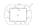
前記課題に対し、特許文献1には、図7に示すように研磨キャリア50において、ワークであるガラス基板Wが収容されるワーク保持孔51の内壁面52に、ガラス基板Wの側端面とワーク保持孔51の内壁面52との当接を防止しつつガラス基板Wをワーク保持孔51内に保持するためのワーク保持片53を備える構成が開示されている。
In response to the above problem, in
前記ワーク保持片53は、超高分子量ポリエチレンにより形成されるため、ガラス基板Wとワーク保持片53との相対摺動に伴うワーク保持片53の摩耗を抑制することができ、研磨工程においてワーク保持片53及びガラス基板Wの削り片が発生することがない。その結果、ガラス基板Wへの残留微粒子の付着を防止することができ、ガラス基板製造及びフォトマスク製造の歩留まりを向上させることができる。また、研磨キャリア50を長時間使用することができる。
Since the
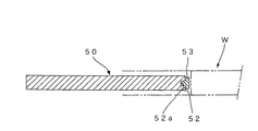
ところで、特許文献1に開示された構成にあっては、図8(図7のA−A矢視断面図)に示すようにガラス基板Wに当接するワーク保持片53は断面T字型に形成されており、その凸部分がワーク保持孔51の内壁面52に形成された凹型溝52aに嵌め込まれ、保持されている。
By the way, in the configuration disclosed in
しかしながら、研磨キャリア50が大型(例えば長辺が1.5m)のものである場合、ワーク保持孔51の内壁面52に対し、ワーク保持片53を嵌合可能な溝加工を施すには高い加工精度が要求され、この加工精度が悪いと、研磨後のガラス基板Wの側面形状に悪影響を及ぼすという課題があった。
また、前記のようにワークがガラス基板Wの場合、ワーク保持片53によってガラス基板Wの側面が擦れて鏡面化し、接触痕となって光反射に差異が生じ、フォトマスク基板としての性能に不具合をもたらすという課題があった。
However, when the
Further, when the work is a glass substrate W as described above, the side surface of the glass substrate W is rubbed by the
本発明は、前記課題を解決するためになされたものであり、ワーク保持孔にワークを保持するとともに一対の定盤の間に狭持され、前記一対の定盤が相対的に回転されることにより前記ワークが研磨される研磨方法において、ワーク側端面における鏡面化の発生を低減し、また、ワーク側面部における傷や欠けの発生を抑制することのできる研磨方法を提供することを目的とする。 The present invention has been made to solve the above-mentioned problems, in which a work is held in a work holding hole and is sandwiched between a pair of surface plates, and the pair of surface plates are relatively rotated. It is an object of the present invention to provide a polishing method capable of reducing the occurrence of mirroring on the work side end surface and suppressing the occurrence of scratches and chips on the work side surface portion in the polishing method in which the work is polished. ..
前記課題を解決するため、本発明に係る研磨方法は、研磨キャリアにおいてワークを保持するためのワーク保持孔に枠状のインナーキャリアを配置し、前記ワークとの少なくとも当接部分をポリテトラフルオロエチレン樹脂により形成したスペーサを、前記インナーキャリアの各辺において枠の内側に突出するように設け、前記研磨キャリアを一対の定盤により狭持し、前記一対の定盤を相対的に回転させることにより前記研磨キャリアに保持されたワークを研磨する研磨方法であって、前記インナーキャリアの各辺に配置されるスペーサを、それぞれ対向する辺に配置されたスペーサの位置と非対称に配置し、前記ワークを研磨する工程を複数回行う際、研磨工程毎に、前記研磨キャリアのワーク保持孔に保持されたワークを180°回転させて配置することに特徴を有する。 In order to solve the above problems, in the polishing method according to the present invention, a frame-shaped inner carrier is arranged in a work holding hole for holding a work in the polishing carrier, and at least a contact portion with the work is made of polytetrafluoroethylene. A spacer formed of resin is provided so as to project inside the frame on each side of the inner carrier, the polishing carrier is sandwiched by a pair of platens, and the pair of plateaus are relatively rotated. A polishing method for polishing a work held by the polishing carrier, in which spacers arranged on each side of the inner carrier are arranged asymmetrically with the positions of spacers arranged on opposite sides, and the work is placed. When the polishing steps are performed a plurality of times, the work held in the work holding holes of the polishing carrier is rotated by 180 ° and arranged for each polishing step .
このような方法によれば、1ワーク端面にポリテトラフルオロエチレン樹脂からなるスペーサが当接し、スペーサの接触部分が圧縮されて基板端面形状に追従して変化するため、ワークの端面形状の変化、接触傷の発生を軽減することができる。
特にワークに対し研磨作業を複数回行う際に、研磨作業毎にワークの向きを変える(ワークを180°回転させる)場合には、前記スペーサは、インナーキャリアの各辺において部分的に配置され、対向する辺同士で非対称の位置に配置される。
これにより、研磨作業毎にワークの向きを変えた際、ワークの側端面の同じ位置にスペーサが接触しないようにし(接触位置の分散)、基板端面形状の変化、接触傷の発生をより低減させることができる。
According to such a method, a spacer made of polytetrafluoroethylene resin comes into contact with the end face of one work, and the contact portion of the spacer is compressed and changes according to the shape of the end face of the substrate. The occurrence of contact scratches can be reduced.
In particular, when the work is subjected to polishing work a plurality of times and the orientation of the work is changed (rotating the work by 180 °) for each polishing work, the spacers are partially arranged on each side of the inner carrier. It is arranged at an asymmetrical position between the opposite sides.
As a result, when the orientation of the work is changed for each polishing operation, the spacers do not come into contact with the same position on the side end face of the work (dispersion of contact positions), and the change in the shape of the end face of the substrate and the occurrence of contact scratches are further reduced. be able to.
本発明によれば、ワーク保持孔にワークを保持するとともに一対の定盤の間に狭持され、前記一対の定盤が相対的に回転されることにより前記ワークが研磨される研磨方法において、ワーク側端面における鏡面化の発生を低減し、また、ワーク側面部における傷や欠けの発生を抑制することのできる研磨方法を得ることができる。 According to the present invention, in a polishing method in which a work is held in a work holding hole and is sandwiched between a pair of surface plates, and the work is polished by relatively rotating the pair of surface plates. It is possible to obtain a polishing method capable of reducing the occurrence of mirroring on the work side end surface and suppressing the occurrence of scratches and chips on the work side surface portion.
以下、本発明に係る研磨方法について、図面を用いながら説明する。
図1は、本発明の研磨方法が実施可能な研磨装置の斜視図である。尚、以下の説明においては、ワークである基板ガラスの両面を研磨する両面研磨装置を例にして説明するが、本発明に係る研磨方法にあっては、両面研磨装置に限らず、片面研磨の装置にも好適に用いることができる。
図1において、研磨装置100は、上下一対の定盤1,2および研磨キャリア10に加え、回転駆動体としての駆動リング3を備える。さらに、遊星歯車4、5、6、7と、環状歯車8とからなる歯車伝達機構9を備えている。
前記定盤1の下面、及び定盤2の上面には、発泡ウレタン、不織布、スウェードのいずれかからなる研磨布が設けられている。また、例えば上側の定盤1に設けられた研磨材供給孔(図示せず)から研磨剤として、酸化セリウム、酸化ジルコニウム、酸化アルミニウム、コロイダルシリカのいずれか、又はこれらの混合物を砥粒として含むものが供給されるようになっている。
Hereinafter, the polishing method according to the present invention will be described with reference to the drawings.
Figure 1 is a perspective view of Migaku Ken methods can be implemented polishing apparatus of the present invention. In the following description, a double-sided polishing device for polishing both sides of the substrate glass as a work will be described as an example, but the polishing method according to the present invention is not limited to the double-sided polishing device, and is not limited to the double-sided polishing device. It can also be suitably used for an apparatus.
In FIG. 1, the
A polishing cloth made of urethane foam, a non-woven fabric, or suede is provided on the lower surface of the
また、前記定盤1の上面、及び定盤2の下面において研磨布の下は、それぞれ同心円状に凹凸(径方向に波状の凹凸)が形成されており、その凹凸量によってガラス基板Wへの研磨圧力分布が制御される。それにより定盤1、2の周速による内外周の研磨効率の差異を無くし、高精度な研磨が可能となる。
Further, on the upper surface of the
前記駆動リング3は、前記キャリア10の周囲に配設され、かつベースB上にガイドレール(図示せず)を介して回転自在に設置されている。また、前記駆動リング3は、外歯車からなり、駆動源M1に伝達歯車11,12を介して連結されている。そして、キャリア公転中心O1の回りに駆動源M1によって回転駆動されるように構成されている。
なお、前記駆動源M1は、前記ベースB上に取付部材(図示せず)を介して固定されている。また、前記ベースBは、ガイドレースR上に進退自在に配設されている。
The
The drive source M1 is fixed on the base B via a mounting member (not shown). Further, the base B is arranged on the guide race R so as to be able to advance and retreat.
前記歯車伝達機構9は、前記したように遊星歯車4、5、6、7および環状歯車8を有し、前記駆動リング3からの回転が前記研磨キャリア10に伝達されるように連結されている。
前記遊星歯車4、5、6、7は、前記駆動リング3の上面部に取付部材20、21、22、23を介して回転自在に保持されている。このうち遊星歯車4,6および遊星歯車5,7はそれぞれ対をなし、キャリア公転中心O1に関して対称な位置に配置されている。また、これら各対の遊星歯車におけるピッチ円の直径比は所定の寸法比に設定されている。
そして、前記遊星歯車4、5、6、7は、前記研磨キャリア10に噛合し、キャリア位置決め及び駆動力伝達用の歯車として機能するように構成されている。
これにより、研磨キャリア10がキャリア公転中心O1より偏心した位置に配置され、研磨時に駆動リング3からの駆動力が研磨キャリア10に伝達される。なお、前記遊星歯車は、この実施形態の場合のように4個の場合のみならず、6個以上の偶数個とすることもできる。
The
The
The
As a result, the
一方、前記環状歯車8は、前記遊星歯車4、5、6、7に噛合する内歯車からなり、前記駆動リング3の上方に配設されている。また、この環状歯車8は、前記両定盤1,2(駆動リング3)の軸線と同一の軸線上に配置され、かつ前記ベースB上に固定されている。
そして、遊星歯車4、5、6、7と共に駆動リング3からの駆動力をキャリア10に自転力および公転力として伝達するように構成されている。
On the other hand, the
Then, together with the
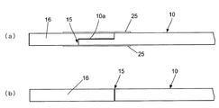
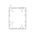
図2は、研磨キャリア10の平面図であり、図3(a)、図3(b)は、図2のB−B矢視断面図である。
前記研磨キャリア10は、図2に示すように複数(図では2つ)の矩形状(ガラス基板Wと相似形)のワーク保持孔15を有し、各ワーク保持孔15には、その内周縁に沿って矩形枠状のインナーキャリア16が設けられている。各インナーキャリア16の内側には、ワークである矩形状のガラス基板Wが保持されている。
尚、ワーク保持孔15内にインナーキャリア16を固定するには、例えば、図3(a)に示すようにワーク保持孔15に段差部10a(段差凹部)を設け、この段差部10aに係合するようインナーキャリア16の外周部を形成すればよい。その場合、研磨キャリア10の本体とインナーキャリア16との繋ぎ目を覆うように超高分子量ポリエチレンにより形成された粘着テープ25を貼って、インナーキャリア16を固定することが望ましい。
或いは、図3(b)に示すように、単純に、ワーク保持孔15の内周面にインナーキャリア16の外周面が接するようにインナーキャリア16を嵌め込む構成としてもよい。
FIG. 2 is a plan view of the polishing
As shown in FIG. 2, the polishing
In order to fix the
Alternatively, as shown in FIG. 3B, the
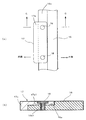
図4に示すインナーキャリア16は、例えばポリカーボネートなどの加工性に優れる樹脂により形成されている。このインナーキャリア16の内側縁部には、図5(a)、図5(b)に示すように段差部16a(段差凹部)が設けられ、この段差部16aには周方向に沿って複数のボルト孔16a1が形成されている。これら複数のボルト孔16a1のうち、例えば2つのボルト孔16a1を利用して1つのスペーサ17が取り付けられる。
The
スペーサ17は、図5(b)に示すように前記インナーキャリア16の段差部16aに係合するように断面L字形の板片であって、更に前記ボルト孔16a1に対応する2つのボルト孔17a1が形成されている。それらボルト孔16a1、17a1の位置を合わせ、そこに超極低頭ボルト18(螺子)を螺入してスペーサ17がインナーキャリア16に対して固定されるようになっている。スペーサ17が固定されると、図5(a)、図5(b)に示すようにスペーサ17の前端部17aがインナーキャリア19の内側に突出した状態となる。尚、本実施の形態においては、図4に示すように各辺に最大4つのスペーサ17(想像線で示す)を取り付けることが可能な構成としている。
As shown in FIG. 5B, the
前記スペーサ17は、研磨工程において被研磨体であるガラス基板Wの側端面に当接し、インナーキャリア16とガラス基板Wとの接触を防止するために設けられている。
スペーサ17の長辺の長さ寸法は、特に限定されるものではないが、スペーサ17の厚さ寸法については、ガラス基板Wとの支持面積が大きくなるように、インナーキャリア16の高さ寸法以下の範囲で出来るだけ厚いことが望ましい。
尚、前記のようにスペーサ17はボルト固定であるため、着脱自在であり、必要に応じて、その数や取付位置を容易に変更することができる。また、研磨作業後にスペーサ17は変形等によって劣化するが、ボルト固定であれば、新たなスペーサ17への交換が容易であり、着脱の作業性、メンテナンス性が向上する。また、ボルト固定のスペーサ17を用いることで、インナーキャリア16に対する複雑な加工が不要であり、製造にかかるコストを大幅に抑えることができる。
The
The length dimension of the long side of the
Since the
また、前記スペーサ17は、摺動性に優れ、且つ硬度の低い樹脂により形成されている。具体的には、摺動性と硬度において超高分子量ポリエチレンより優位なPTFE(ポリテトラフルオロエチレン)樹脂で形成される。特に軟質PTFE樹脂であることが望ましいが、機械加工が困難であるため、軟質PTFE樹脂を用いる場合には、例えばポリカーボネート製のスペーサの表面部分(基板端面との当接部分)に、シート状またはブロック状の軟質PTFE樹脂を接着すればよい。このように摺動性に優れ、且つ硬度の低い樹脂によりスペーサ17を形成することにより、研磨中におけるガラス基板Wとの摺接が生じた際、ガラス基板Wの端面形状の部分的変化(凹など)や擦れによる傷の発生を抑制することができる。
尚、本発明にあっては、ガラス基板Wに対する片面研磨、両面研磨のいずれにも適用することができるが、両面研磨プロセスでは、ガラス基板Wの上面と下面の両方が強く摺動されることで、ワーク保持孔15内でのガラス基板Wの微振動が大きくなるため、上記の本発明の効果がより好適に発揮される。
Further, the
In the present invention, it can be applied to both single-sided polishing and double-sided polishing of the glass substrate W, but in the double-sided polishing process, both the upper surface and the lower surface of the glass substrate W are strongly slid. As a result, the slight vibration of the glass substrate W in the
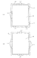
また、前記スペーサ17は、図6(a)、図6(b)に示すように、インナーキャリア16の各辺において部分的に配置される。図6(a)は、対向する辺同士で異なる位置にスペーサ17が配置される例を示す。図6(b)では対向する辺同士で同じ位置にスペーサ17が配置される例を示す。いずれも各辺に2つのスペーサ17が配置された例である。
ここで、1枚のガラス基板Wに対する研磨作業を複数回行う際に、各研磨作業ごとにガラス基板Wの向きを変える(基板を180°回転させる)場合には、図6(b)に示す配置よりも図6(a)の配置が好ましい。これは、後述するように、1枚のガラス基板Wに対する研磨作業を複数回行う際に、各研磨作業ごとにガラス基板Wの向きを変える(基板を180°回転させる)ことで、ガラス基板Wの側端面の同じ位置にスペーサ17が接触しないようにし(接触位置の分散)、基板端面形状の変化、接触傷の発生をより低減させるためである。
Further, as shown in FIGS. 6A and 6B, the
Here, when the polishing work on one glass substrate W is performed a plurality of times and the orientation of the glass substrate W is changed (rotating the substrate 180 °) for each polishing operation, it is shown in FIG. 6 (b). The arrangement shown in FIG. 6A is preferable to the arrangement. As will be described later, this is done by changing the orientation of the glass substrate W (rotating the substrate 180 °) for each polishing operation when the polishing operation for one glass substrate W is performed a plurality of times. This is to prevent the
このように構成された研磨装置100においてガラス基板Wの両面研磨を行う場合、図1のように定盤1に対し定盤2が上昇し離れた状態において、研磨キャリア10のワーク保持孔15にガラス基板Wを配置する。即ち、インナーキャリア16の各辺において水平方向内側に突出するよう設けられたスペーサ17の内側にガラス基板Wを配置する。インナーキャリア16に対するスペーサ17の取付位置は、好ましくは図6(a)に示したように対向する辺において異なる位置に配置される。
When double-sided polishing of the glass substrate W is performed by the polishing
次いで、駆動リング3を時計方向(矢印m1方向)に、また下方定盤2を時計方向(矢印m2方向)に回転駆動する。この場合、駆動リング3が回転駆動されると、この回転方向(矢印m1方向)に遊星歯車4、5、6、7が環状歯車8上を転動する。
これに伴い、研磨キャリア中心(研磨キャリア自転中心O2)を回転中心として矢印m3方向に研磨キャリア10が回転(自転)しながら、駆動リング3の回転中心(キャリア公転中心O1)を中心として矢印m1方向に研磨キャリア10が回転(公転)する。
なお、研磨キャリア10の自転速度および公転速度は、共に駆動リング2の回転速度に応じて決定される。
したがって、研磨時に駆動リング2が回転駆動されると、この駆動力が歯車伝達機構3(遊星歯車4、5、6、7および環状歯車8)を介し研磨キャリア10に自転力および回転力として伝達される。
Next, the
Along with this, while the polishing
The rotation speed and the revolution speed of the polishing
Therefore, when the
例えば、研磨作業は各ガラス基板Wについて複数回数(偶数)行われ、研磨作業毎に、各ワーク保持孔15においてガラス基板Wの向きが変えられる。即ち、ガラス基板Wの配置方向が180°回転される。ここで、インナーキャリア16に対するスペーサ17の取付位置は、例えば図6(a)に示す配置としているため、ガラス基板Wの各辺においてスペーサ17が接する箇所が異なる箇所となり、下定盤1及び上定盤2の凸量や周速差の影響を極力小さくすることができる。
また、ガラス基板Wの側面に接するスペーサ17は、摺動性に優れ、低い硬度の材料、具体的には、PTFE(ポリテトラフルオロエチレン)樹脂で形成されるため、基板端面形状の変化、接触傷の発生が軽減される。
For example, the polishing operation is performed a plurality of times (even number) for each glass substrate W, and the orientation of the glass substrate W is changed in each
Further, since the
以上のように本発明に係る実施の形態によれば、研磨キャリア10のワーク保持孔15に、加工性に優れるインナーキャリア16を置き、インナーキャリア16に複数のスペーサ17をボルト固定するものとした。
これによりガラス基板Wの端面にPTFEからなるスペーサ17が当接し、スペーサ17の接触部分が圧縮されて基板端面形状に追従して変化するため、ガラス基板Wの端面形状の変化、接触傷の発生を軽減することができる。
特に各ガラス基板Wに対し研磨作業を複数回行う際に、研磨作業毎にガラス基板Wの向きを変える(基板を180°回転させる)場合には、前記スペーサ17は、インナーキャリア16の各辺において部分的に配置され、対向する辺同士で非対称の位置に配置される。
これにより、研磨作業毎にガラス基板Wの向きを変えた際、ガラス基板Wの側端面の同じ位置にスペーサ17が接触しないようにし(接触位置の分散)、基板端面形状の変化、接触傷の発生をより低減させることができる。
As described above, according to the embodiment of the present invention, the
As a result, the
In particular, when the direction of the glass substrate W is changed (rotating the substrate by 180 °) for each polishing operation when the polishing operation is performed on each glass substrate W a plurality of times, the
As a result, when the orientation of the glass substrate W is changed for each polishing operation, the
以下、本発明を実施例に基づき具体的に説明するが、本発明は下記に示す実施例により制限されるものではない。 Hereinafter, the present invention will be specifically described based on examples, but the present invention is not limited to the examples shown below.
[実施例1]
実施例1では、本実施の形態に示したように、研磨キャリアに形成されたワーク保持孔に、ポリカーボネート製の矩形枠状のインナーキャリアを設け、その内周縁部にPTFE樹脂製のスペーサを複数設けた。インナーキャリアの各辺に設けた複数のスペーサは、対向する辺側と対称的に同じ位置に配置した。
[Example 1]
In the first embodiment, as shown in the present embodiment, a rectangular frame-shaped inner carrier made of polycarbonate is provided in the work holding hole formed in the polishing carrier, and a plurality of spacers made of PTFE resin are provided on the inner peripheral edge thereof. Provided. A plurality of spacers provided on each side of the inner carrier were arranged at the same position symmetrically with the opposite side.
その他の条件として、研磨対象は、縦800mm×横920mm×厚さ10mmのLCD用フォトマスク基板2枚を、研磨キャリアの二つのワーク保持孔に配置した。研磨剤として酸化セリウム、研磨布として硬質スエードパッドを用いた。
また、上下定盤サイズはφ2400mm、定盤形状は上定盤が130μm凸、下定盤が20μm凹、研磨圧力が49g/cm2、定盤回転数が、下定盤が6.8rpm、上定盤を固定、研磨キャリア回転数が3.4rpm、キャリア揺動周期を2.5min、研磨ローテーションを2回(180°旋回)とした。
As another condition, two photomask substrates for LCD having a length of 800 mm, a width of 920 mm, and a thickness of 10 mm were arranged in two work holding holes of the polishing carrier. Cerium oxide was used as the polishing agent, and a hard suede pad was used as the polishing cloth.
The upper and lower surface plates are φ2400 mm, the upper surface plate is 130 μm convex, the lower surface plate is 20 μm concave, the polishing pressure is 49 g / cm 2 , the surface plate rotation speed is 6.8 rpm for the lower surface plate, and the upper surface plate. The polishing carrier rotation speed was 3.4 rpm, the carrier rocking cycle was 2.5 min, and the polishing rotation was twice (180 ° swivel).
研磨後に、基板端面の状態を観察したところ、部分的な鏡面が形成されたが、光沢計の値は5〜40%と低かった。また、ワーク側面部において目立つ傷や欠けの発生は認められなかった。 When the state of the end face of the substrate was observed after polishing, a partial mirror surface was formed, but the value of the gloss meter was as low as 5 to 40%. In addition, no noticeable scratches or chips were found on the side surface of the work.
[実施例2]
実施例2では、インナーキャリアの各辺に設けた複数のスペーサは、対向する辺側と非対称の位置に配置し、研磨作業を行った。その他条件は、実施例1と同じである。
研磨後に、基板端面の状態を観察したところ、部分的な鏡面が形成された。光沢計の値は20%以下となり、実施例1の場合よりも良化された。また、ワーク側面部において目立つ傷や欠けの発生は認められなかった。
[Example 2]
In the second embodiment, the plurality of spacers provided on each side of the inner carrier were arranged at positions asymmetrical with the opposite side, and polishing work was performed. Other conditions are the same as in Example 1.
When the state of the end face of the substrate was observed after polishing, a partial mirror surface was formed. The value of the gloss meter was 20% or less, which was better than that of Example 1. In addition, no noticeable scratches or chips were found on the side surface of the work.
[比較例1]
比較例1として、インナーキャリア(スペーサ無し)にワーク(LCD用フォトマスク基板)を配置し、研磨作業を行った。その他条件は、実施例1と同じである。
研磨後に、基板端面の状態を観察したところ、部分的な鏡面が形成され、光沢計の値は70%と高かった。また、その鏡面部分は強く磨かれたように鏡面化していた。
[Comparative Example 1]
As Comparative Example 1, a work (photomask substrate for LCD) was placed on an inner carrier (without spacers), and polishing work was performed. Other conditions are the same as in Example 1.
When the state of the end face of the substrate was observed after polishing, a partial mirror surface was formed, and the value of the gloss meter was as high as 70%. In addition, the mirror surface part was mirrored as if it was strongly polished.
以上の実施例の結果から、本発明によれば、ワーク側端面における鏡面化を低減し、また、ワーク側面部における傷や欠けの発生を抑制することができることを確認した。 From the results of the above examples, it was confirmed that according to the present invention, mirroring on the work side end surface can be reduced, and the occurrence of scratches and chips on the work side surface can be suppressed.
1 定盤
2 定盤
10 研磨キャリア
15 ワーク保持孔
16 インナーキャリア
16a 段差部
16a1 ボルト孔
17 スペーサ
17a 前端部
17a1 ボルト孔
18 超極低頭ボルト(螺子)
W ガラス基板(ワーク)
1
W glass substrate (work)
Claims (1)
前記ワークとの少なくとも当接部分をポリテトラフルオロエチレン樹脂により形成したスペーサを、前記インナーキャリアの各辺において枠の内側に突出するように設け、
前記研磨キャリアを一対の定盤により狭持し、前記一対の定盤を相対的に回転させることにより前記研磨キャリアに保持されたワークを研磨する研磨方法であって、
前記インナーキャリアの各辺に配置されるスペーサを、それぞれ対向する辺に配置されたスペーサの位置と非対称に配置し、
前記ワークを研磨する工程を複数回行う際、研磨工程毎に、前記研磨キャリアのワーク保持孔に保持されたワークを180°回転させて配置することを特徴とする研磨方法。 A frame-shaped inner carrier is placed in the work holding hole for holding the work in the polishing carrier.
A spacer having at least a contact portion with the work formed of a polytetrafluoroethylene resin is provided so as to project inside the frame on each side of the inner carrier.
A polishing method in which the polishing carrier is held by a pair of surface plates and the work held by the polishing carriers is polished by rotating the pair of surface plates relatively .
The spacers arranged on each side of the inner carrier are arranged asymmetrically with the positions of the spacers arranged on the opposite sides.
A polishing method characterized in that when the steps of polishing the work are performed a plurality of times, the work held in the work holding holes of the polishing carrier is rotated by 180 ° and arranged for each polishing step.
Priority Applications (1)
| Application Number | Priority Date | Filing Date | Title |
|---|---|---|---|
| JP2016250764A JP6777530B2 (en) | 2016-12-26 | 2016-12-26 | Polishing method |
Applications Claiming Priority (1)
| Application Number | Priority Date | Filing Date | Title |
|---|---|---|---|
| JP2016250764A JP6777530B2 (en) | 2016-12-26 | 2016-12-26 | Polishing method |
Publications (2)
| Publication Number | Publication Date |
|---|---|
| JP2018103293A JP2018103293A (en) | 2018-07-05 |
| JP6777530B2 true JP6777530B2 (en) | 2020-10-28 |
Family
ID=62786432
Family Applications (1)
| Application Number | Title | Priority Date | Filing Date |
|---|---|---|---|
| JP2016250764A Active JP6777530B2 (en) | 2016-12-26 | 2016-12-26 | Polishing method |
Country Status (1)
| Country | Link |
|---|---|
| JP (1) | JP6777530B2 (en) |
Family Cites Families (8)
| Publication number | Priority date | Publication date | Assignee | Title |
|---|---|---|---|---|
| JPS61209877A (en) * | 1985-03-14 | 1986-09-18 | Nitto Hatsujo:Kk | Lapping carrier |
| DE3524978A1 (en) * | 1985-07-12 | 1987-01-22 | Wacker Chemitronic | METHOD FOR DOUBLE-SIDED REMOVAL MACHINING OF DISK-SHAPED WORKPIECES, IN PARTICULAR SEMICONDUCTOR DISCS |
| JPH0457669A (en) * | 1990-06-28 | 1992-02-25 | Furukawa Electric Co Ltd:The | Grinding and polishing method for metal disc |
| US6030280A (en) * | 1997-07-23 | 2000-02-29 | Speedfam Corporation | Apparatus for holding workpieces during lapping, honing, and polishing |
| JPH11254303A (en) * | 1998-03-11 | 1999-09-21 | Daido Steel Co Ltd | Lapping machine |
| JP2002217149A (en) * | 2001-01-19 | 2002-08-02 | Shin Etsu Handotai Co Ltd | Wafer polishing apparatus and method |
| JP2012111001A (en) * | 2010-11-25 | 2012-06-14 | Nikon Corp | Work carrier and polishing device having work carrier |
| JP2014172148A (en) * | 2013-03-12 | 2014-09-22 | Sii Crystal Technology Inc | Carrier |
-
2016
- 2016-12-26 JP JP2016250764A patent/JP6777530B2/en active Active
Also Published As
| Publication number | Publication date |
|---|---|
| JP2018103293A (en) | 2018-07-05 |
Similar Documents
| Publication | Publication Date | Title |
|---|---|---|
| JP5233888B2 (en) | Method for manufacturing carrier for double-side polishing apparatus, carrier for double-side polishing apparatus and double-side polishing method for wafer | |
| US8414360B2 (en) | Double side polishing apparatus and carrier therefor | |
| JP5382732B2 (en) | Float glass polishing system | |
| JP4519130B2 (en) | Pressure transfer grinding of AMLCD substrate edge | |
| KR20130108514A (en) | Glass substrate and method for manufacturing glass substrate | |
| US8460061B2 (en) | Method for producing large-size synthetic quartz glass substrate | |
| KR20070096879A (en) | Planar Polishing Apparatus and Polishing Method | |
| TW201722617A (en) | Carrier ring, grinding device, and grinding method | |
| KR101273729B1 (en) | Method and device for polishing plate-like body | |
| JP6777530B2 (en) | Polishing method | |
| JP2004058201A (en) | Work polishing method and manufacturing method of substrate for electronic device | |
| JP2013018065A (en) | Method for grinding thin sheet-like workpiece and double-end surface grinder | |
| JP5231918B2 (en) | Mask blank substrate manufacturing method and double-side polishing apparatus | |
| JP4614851B2 (en) | Surface polishing equipment | |
| JP2014073573A (en) | Polishing device | |
| JP2019166607A (en) | Polishing machine | |
| CN221290711U (en) | Belt grinder | |
| JP4143563B2 (en) | Work holding device and double-sided processing device | |
| JP2007057638A (en) | Chamfered large substrate and manufacturing method thereof | |
| JP4289764B2 (en) | Tape polishing equipment | |
| JPH07178655A (en) | Polishing method for glass sheet | |
| JP2009184074A (en) | Polishing device | |
| JP2007098542A (en) | Double-side polishing equipment | |
| JP2007007748A (en) | Polishing device and double-disc polishing device | |
| JP2007098543A (en) | Work carrier and double-side polishing machine |
Legal Events
| Date | Code | Title | Description |
|---|---|---|---|
| A621 | Written request for application examination |
Free format text: JAPANESE INTERMEDIATE CODE: A621 Effective date: 20190613 |
|
| A977 | Report on retrieval |
Free format text: JAPANESE INTERMEDIATE CODE: A971007 Effective date: 20200624 |
|
| A131 | Notification of reasons for refusal |
Free format text: JAPANESE INTERMEDIATE CODE: A131 Effective date: 20200707 |
|
| A521 | Request for written amendment filed |
Free format text: JAPANESE INTERMEDIATE CODE: A523 Effective date: 20200831 |
|
| TRDD | Decision of grant or rejection written | ||
| A01 | Written decision to grant a patent or to grant a registration (utility model) |
Free format text: JAPANESE INTERMEDIATE CODE: A01 Effective date: 20201001 |
|
| A61 | First payment of annual fees (during grant procedure) |
Free format text: JAPANESE INTERMEDIATE CODE: A61 Effective date: 20201008 |
|
| R150 | Certificate of patent or registration of utility model |
Ref document number: 6777530 Country of ref document: JP Free format text: JAPANESE INTERMEDIATE CODE: R150 |
|
| R250 | Receipt of annual fees |
Free format text: JAPANESE INTERMEDIATE CODE: R250 |
|
| S533 | Written request for registration of change of name |
Free format text: JAPANESE INTERMEDIATE CODE: R313533 |
|
| R350 | Written notification of registration of transfer |
Free format text: JAPANESE INTERMEDIATE CODE: R350 |
|
| R250 | Receipt of annual fees |
Free format text: JAPANESE INTERMEDIATE CODE: R250 |
|
| R250 | Receipt of annual fees |
Free format text: JAPANESE INTERMEDIATE CODE: R250 |