JP6760228B2 - Wire harness wiring device and slide wiring device - Google Patents
Wire harness wiring device and slide wiring device Download PDFInfo
- Publication number
- JP6760228B2 JP6760228B2 JP2017152205A JP2017152205A JP6760228B2 JP 6760228 B2 JP6760228 B2 JP 6760228B2 JP 2017152205 A JP2017152205 A JP 2017152205A JP 2017152205 A JP2017152205 A JP 2017152205A JP 6760228 B2 JP6760228 B2 JP 6760228B2
- Authority
- JP
- Japan
- Prior art keywords
- protector
- wire harness
- case
- slider
- opening
- Prior art date
- Legal status (The legal status is an assumption and is not a legal conclusion. Google has not performed a legal analysis and makes no representation as to the accuracy of the status listed.)
- Active
Links
Images


Classifications
-
- B—PERFORMING OPERATIONS; TRANSPORTING
- B60—VEHICLES IN GENERAL
- B60R—VEHICLES, VEHICLE FITTINGS, OR VEHICLE PARTS, NOT OTHERWISE PROVIDED FOR
- B60R16/00—Electric or fluid circuits specially adapted for vehicles and not otherwise provided for; Arrangement of elements of electric or fluid circuits specially adapted for vehicles and not otherwise provided for
- B60R16/02—Electric or fluid circuits specially adapted for vehicles and not otherwise provided for; Arrangement of elements of electric or fluid circuits specially adapted for vehicles and not otherwise provided for electric constitutive elements
- B60R16/023—Electric or fluid circuits specially adapted for vehicles and not otherwise provided for; Arrangement of elements of electric or fluid circuits specially adapted for vehicles and not otherwise provided for electric constitutive elements for transmission of signals between vehicle parts or subsystems
- B60R16/027—Electric or fluid circuits specially adapted for vehicles and not otherwise provided for; Arrangement of elements of electric or fluid circuits specially adapted for vehicles and not otherwise provided for electric constitutive elements for transmission of signals between vehicle parts or subsystems between relatively movable parts of the vehicle, e.g. between steering wheel and column
-
- B—PERFORMING OPERATIONS; TRANSPORTING
- B60—VEHICLES IN GENERAL
- B60R—VEHICLES, VEHICLE FITTINGS, OR VEHICLE PARTS, NOT OTHERWISE PROVIDED FOR
- B60R16/00—Electric or fluid circuits specially adapted for vehicles and not otherwise provided for; Arrangement of elements of electric or fluid circuits specially adapted for vehicles and not otherwise provided for
- B60R16/02—Electric or fluid circuits specially adapted for vehicles and not otherwise provided for; Arrangement of elements of electric or fluid circuits specially adapted for vehicles and not otherwise provided for electric constitutive elements
- B60R16/0207—Wire harnesses
- B60R16/0215—Protecting, fastening and routing means therefor
-
- B—PERFORMING OPERATIONS; TRANSPORTING
- B60—VEHICLES IN GENERAL
- B60N—SEATS SPECIALLY ADAPTED FOR VEHICLES; VEHICLE PASSENGER ACCOMMODATION NOT OTHERWISE PROVIDED FOR
- B60N2/00—Seats specially adapted for vehicles; Arrangement or mounting of seats in vehicles
- B60N2/02—Seats specially adapted for vehicles; Arrangement or mounting of seats in vehicles the seat or part thereof being movable, e.g. adjustable
- B60N2/04—Seats specially adapted for vehicles; Arrangement or mounting of seats in vehicles the seat or part thereof being movable, e.g. adjustable the whole seat being movable
- B60N2/06—Seats specially adapted for vehicles; Arrangement or mounting of seats in vehicles the seat or part thereof being movable, e.g. adjustable the whole seat being movable slidable
- B60N2/07—Slide construction
- B60N2/0722—Constructive details
-
- H—ELECTRICITY
- H02—GENERATION; CONVERSION OR DISTRIBUTION OF ELECTRIC POWER
- H02G—INSTALLATION OF ELECTRIC CABLES OR LINES, OR OF COMBINED OPTICAL AND ELECTRIC CABLES OR LINES
- H02G11/00—Arrangements of electric cables or lines between relatively-movable parts
- H02G11/006—Arrangements of electric cables or lines between relatively-movable parts using extensible carrier for the cable, e.g. self-coiling spring
-
- H—ELECTRICITY
- H02—GENERATION; CONVERSION OR DISTRIBUTION OF ELECTRIC POWER
- H02G—INSTALLATION OF ELECTRIC CABLES OR LINES, OR OF COMBINED OPTICAL AND ELECTRIC CABLES OR LINES
- H02G3/00—Installations of electric cables or lines or protective tubing therefor in or on buildings, equivalent structures or vehicles
- H02G3/02—Details
- H02G3/04—Protective tubing or conduits, e.g. cable ladders or cable troughs
- H02G3/0462—Tubings, i.e. having a closed section
- H02G3/0475—Tubings, i.e. having a closed section formed by a succession of articulated units
-
- H—ELECTRICITY
- H02—GENERATION; CONVERSION OR DISTRIBUTION OF ELECTRIC POWER
- H02G—INSTALLATION OF ELECTRIC CABLES OR LINES, OR OF COMBINED OPTICAL AND ELECTRIC CABLES OR LINES
- H02G3/00—Installations of electric cables or lines or protective tubing therefor in or on buildings, equivalent structures or vehicles
- H02G3/02—Details
- H02G3/04—Protective tubing or conduits, e.g. cable ladders or cable troughs
- H02G3/0462—Tubings, i.e. having a closed section
Description
本明細書に開示された技術は、ワイヤーハーネス配索装置、及びこれを用いたスライド配線装置に関する。 The techniques disclosed herein relate to wire harness routing devices and slide wiring devices using them.
従来、車両と、車両に搭載されたスライドシート等のスライド部品と、の間を電気的に接続するワイヤーハーネス配索装置として、特開2012−45994号公報に記載のものが知られている。このワイヤーハーネス配索装置は、レールと、レールに対してスライド移動可能に取り付けられたスライダと、レール内に配されて一端側がスライダに連結されたワイヤーハーネスと、レールから導出されたワイヤーハーネスを収容するワイヤーハーネス収容部と、を備える。 Conventionally, a wire harness routing device for electrically connecting a vehicle and a slide component such as a slide sheet mounted on the vehicle is known as described in Japanese Patent Application Laid-Open No. 2012-45994. This wire harness routing device includes a rail, a slider attached to the rail so as to be slidable, a wire harness arranged in the rail and one end connected to the slider, and a wire harness derived from the rail. It is provided with a wire harness accommodating portion for accommodating.
上記のワイヤーハーネス配索装置は、スライダが取り付けられたレールと、ワイヤーハーネスが収容されたワイヤーハーネス収容部と、がそれぞれ異なる場所で作製され、更に、両部材の組み付けを担当する場所において、レールとワイヤーハーネス収容部とが組み付けられるようになっている。上記の部材が作成され、又は組み付けられる場所としては、一の工場内の異なる場所、異なる工場、異なるメーカー等が例示される。 In the above wire harness routing device, the rail to which the slider is attached and the wire harness accommodating portion in which the wire harness is housed are manufactured in different places, and further, the rail is in charge of assembling both members. And the wire harness housing are assembled. Examples of places where the above members are created or assembled include different places in one factory, different factories, different manufacturers, and the like.
レールとワイヤーハーネス収容部とが組み付けられる前の状態においては、ワイヤーハーネス収容部からワイヤーハーネスが導出された状態になっている。導出されたワイヤーハーネスには、プロテクタ部材とコネクタが取り付けられている。このため、組み付けを担当する場所へワイヤーハーネス収容部を輸送する際に、ワイヤーハーネス収容部から導出されたワイヤーハーネス、プロテクタ部材、及びコネクタが、輸送時の振動によって揺動し、異物と接触することによって不具合を生じることが懸念される。 In the state before the rail and the wire harness accommodating portion are assembled, the wire harness is in a state of being derived from the wire harness accommodating portion. A protector member and a connector are attached to the derived wire harness. Therefore, when transporting the wire harness accommodating portion to the place in charge of assembly, the wire harness, protector member, and connector derived from the wire harness accommodating portion swing due to vibration during transportation and come into contact with foreign matter. There is a concern that this may cause problems.
本明細書に開示された技術は上記のような事情に基づいて完成されたものであって、輸送時において異物との接触が抑制されたワイヤーハーネス配索装置を提供することを目的とする。 The technique disclosed in the present specification has been completed based on the above circumstances, and an object of the present invention is to provide a wire harness routing device in which contact with a foreign substance is suppressed during transportation.
本明細書に開示された技術は、ワイヤーハーネス配索装置であって、ワイヤーハーネスと、前記ワイヤーハーネスが収容されると共に、開口部を有して前記開口部から前記ワイヤーハーネスを導出又は導入可能であるケースと、前記開口部から導出された前記ワイヤーハーネスに取り付けられたプロテクタと、前記ケースと前記プロテクタとを着脱可能に係合する係合手段と、を備える。 The technique disclosed herein is a wire harness routing device that accommodates a wire harness and the wire harness and has an opening so that the wire harness can be derived or introduced from the opening. A case, a protector attached to the wire harness led out from the opening, and an engaging means for detachably engaging the case and the protector are provided.
上記の構成によれば、ケースの開口部から導出されたワイヤーハーネスを、ケースに係合させることができる。これにより、ワイヤーハーネス配索装置を輸送する際に、ケースの開口部から導出されたワイヤーハーネスは、振動等を受けた場合でも揺れ動かないようになっている。これにより、ワイヤーハーネスが異物と衝突することを抑制することができる。 According to the above configuration, the wire harness derived from the opening of the case can be engaged with the case. As a result, when transporting the wire harness routing device, the wire harness derived from the opening of the case does not sway even when it receives vibration or the like. As a result, it is possible to prevent the wire harness from colliding with a foreign object.
本明細書に開示された技術の実施態様としては以下の態様が好ましい。 The following embodiments are preferred as embodiments of the techniques disclosed herein.
前記係合手段は、前記ケースに設けられた係合部と、前記プロテクタに設けられた被係合部である。 The engaging means is an engaging portion provided on the case and an engaged portion provided on the protector.
上記の構成によれば、係合手段が、ケース及びプロテクタと異なる部材で構成される場合に比べて、部品点数を少なくすることができる。 According to the above configuration, the number of parts can be reduced as compared with the case where the engaging means is composed of a member different from the case and the protector.
前記係合部は、前記開口部の孔縁部に設けられていることが好ましい。 It is preferable that the engaging portion is provided at the hole edge portion of the opening.
上記の構成によれば、ワイヤーハーネス収容部から引き出された状態のワイヤーハーネスを、開口部からワイヤーハーネス収容部内に押し込んでいくことにより、プロテクタはケースの開口部へと近付いていく。この開口部の孔縁部に、プロテクタの被係合部と係合する係合部が設けられているので、ワイヤーハーネスをワイヤーハーネス収容部内へ押し込む動作と、開口部の孔縁部に形成された係合部へプロテクタを接近させる動作とを同時に行うことができるので、プロテクタとケースとの間の位置決めを容易に行うことができる。 According to the above configuration, the protector approaches the opening of the case by pushing the wire harness pulled out from the wire harness accommodating portion into the wire harness accommodating portion through the opening. Since an engaging portion that engages with the engaged portion of the protector is provided at the hole edge portion of this opening portion, the operation of pushing the wire harness into the wire harness accommodating portion and the formation of the hole edge portion of the opening portion. Since the operation of bringing the protector closer to the engaging portion can be performed at the same time, the positioning between the protector and the case can be easily performed.
前記係合手段による前記ケースと前記プロテクタとの係合が解除される方向は、前記開口部から前記ワイヤーハーネスが導出される方向に平行であることが好ましい。 The direction in which the case and the protector are disengaged by the engaging means is preferably parallel to the direction in which the wire harness is led out from the opening.
上記の構成によれば、開口部からワイヤーハーネスが導出される方向に沿ってワイハーハーネスを引っ張ることにより、ケースとプロテクタとの係合を解除することができる。これにより、ワイヤーハーネスを引っ張るという簡易な手法により、ケースとプロテクタとの係合を解除することができる。 According to the above configuration, the engagement between the case and the protector can be disengaged by pulling the Waiha harness along the direction in which the wire harness is led out from the opening. As a result, the engagement between the case and the protector can be disengaged by a simple method of pulling the wire harness.
本明細書に開示された技術は、スライド配線装置であって、ワイヤーハーネス配索装置と、前記ケースの前記開口部に一方の端部が配されると共に、前記開口部から前記ワイヤーハーネスが導出される方向に沿って延びるレールと、前記レールに対してスライド可能に配されると共に、前記プロテクタと固定されたスライダと、を備える。 The technique disclosed in the present specification is a slide wiring device, in which one end is arranged in the wire harness wiring device and the opening of the case, and the wire harness is derived from the opening. It is provided with a rail extending along the direction of the rail, and a slider slidably arranged with respect to the rail and fixed to the protector.
上記の構成によれば、ワイヤーハーネス配索装置を、スライド配線装置に適用することができる。 According to the above configuration, the wire harness wiring device can be applied to the slide wiring device.
また、スライダをスライド移動させることにより、スライダに固定されたプロテクタも移動させることができる。この結果、開口部からワイヤーハーネスが導出される方向に沿ってスライダを移動させることにより、スライダに固定されたプロテクタを介して、ワイハーハーネスを引っ張ることができる。これにより、ケースとプロテクタとの係合を解除することができる。このように、スライダをスライドさせるという簡易な手法により、ケースとプロテクタとの係合を解除することができる。 Further, by sliding the slider, the protector fixed to the slider can also be moved. As a result, the wire harness can be pulled through the protector fixed to the slider by moving the slider along the direction in which the wire harness is led out from the opening. As a result, the case and the protector can be disengaged. In this way, the engagement between the case and the protector can be disengaged by a simple method of sliding the slider.
前記プロテクタと前記ケースとが係合した状態で、前記プロテクタの少なくとも一部は、前記スライダがスライド移動可能な領域内に位置しており、前記プロテクタ及び前記スライダの一方は、他方と仮係止する仮係止部を有していることが好ましい。 With the protector and the case engaged, at least a portion of the protector is located within a slidable area of the slider, and one of the protector and the slider is temporarily locked to the other. It is preferable to have a temporary locking portion.
スライダがレールに配された状態で、スライダとプロテクタとの組み付け作業を行う場合、レールの内側の領域で組み付け作業を行う必要が生じる場合がある。この場合、レールの内側という狭い空間内での作業となってしまうため、作業効率が低下する。これを避けるために、一旦、スライダをレールから外した後に、スライダとプロテクタとの組み付け作業を行い、再びスライダをレールに取り付けることが考えられるが、作業が煩雑となる。 When assembling the slider and the protector while the slider is arranged on the rail, it may be necessary to perform the assembling work in the area inside the rail. In this case, the work is performed in a narrow space inside the rail, so that the work efficiency is lowered. In order to avoid this, it is conceivable that the slider is once removed from the rail, the slider and the protector are assembled, and the slider is attached to the rail again, but the work becomes complicated.
上記の構成によれば、プロテクタがケースに係合された状態で、スライダをスライド移動させることにより、プロテクタとスライダとを仮係止することができる。これにより、プロテクタとスライダとを仮係止した状態で、プロテクタとスライダとを固定することができるので、プロテクタとスライダとの固定作業の効率を向上させることができる。 According to the above configuration, the protector and the slider can be temporarily locked by sliding the slider while the protector is engaged with the case. As a result, the protector and the slider can be fixed in a state where the protector and the slider are temporarily locked, so that the efficiency of the fixing work between the protector and the slider can be improved.
本明細書に開示された技術によれば、ワイヤーハーネス配索装置から導出されたワイヤーハーネスが異物と接触することが抑制される。 According to the technique disclosed herein, the wire harness derived from the wire harness routing device is prevented from coming into contact with foreign matter.
<実施形態1>
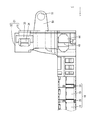
本明細書に開示された技術の実施形態1について、図1から図19を参照しつつ説明する。本実施形態に係るスライド配線装置10は、ワイヤーハーネス配索装置11と、レール12と、スライダ13と、を備える。本実施形態のスライド配線装置10は、自動車等の車両(図示せず)の車体(図示せず)とシート14との間にワイヤーハーネス15を配索するものである。以下では、図1のX方向を右方、Y方向を前方、Z方向を上方として説明する。複数の同一部材については、一の部材にのみ符号を付し、他の部材については符号を省略する場合がある。
<Embodiment 1>
Embodiment 1 of the technique disclosed in the present specification will be described with reference to FIGS. 1 to 19 . The
シート14は、図1に示すように、車体の乗員室の床上にボルト締結等によって固定された金属製のレール12に対して前後方向にスライド可能とされている。シート14には、例えば、電動リクライニング装置、シートヒータ、乗員の着座の有無を検出するセンサ、シートベルトの装着の有無を検出するセンサなどの各種電装品が備えられている。シート14は、レール12にスライド可能に配されたスライダ13に取り付けられている。
As shown in FIG. 1, the
(ワイヤーハーネス15)
ワイヤーハーネス15は、車体の床上(のマットやパネル等の下)や床下に配索されており、車体側ではECU(Electronic Control Unit)等の機器に接続されている。このワイヤーハーネス15を介して車体側の機器とシート14の電装品との間の給電や信号の送受が行われる。
(Wire harness 15)
The
シート14と車体との間に配索されたワイヤーハーネス15は、図2に示すように、シート14の下のレール12と、ケース16と、に挿通されている。ワイヤーハーネス15は、複数(本実施形態では4本)の電線17と、複数本の電線17を覆う外装体18とを備えている。各電線17は、金属製の導体部が絶縁層で被覆されており、シート14に備えられた各種電装品に接続されている。
As shown in FIG. 2, the
外装体18は、絶縁性の合成樹脂製であって、電線17を覆って帯状に延びている。換言すると、複数の電線17は、外装体18によって外装されている。外装体18は、筒状をなす複数のユニット19が、ユニット19と一体に形成されたヒンジ20で連結されてなる。外装体18はヒンジ20において湾曲可能に形成されている。
The
(ワイヤーハーネス配索装置11)
ワイヤーハーネス配索装置11は、ワイヤーハーネス15と、ワイヤーハーネス15を収容するケース16と、ケース16から導出されたワイヤーハーネス15に取り付けられたプロテクタ21と、ケース16とプロテクタ21とを着脱可能に係合する係合手段22と、を備える。
(Wire harness routing device 11)
The wire
ケース16を形成する材料は、合成樹脂又は金属等、必要に応じて適宜に選択される。図3に示すように、ケース16には、ブラケット23が設けられている。このブラケット23を貫通する貫通孔24にボルト(図示せず)が挿通され、ボルトが車体に螺着されることにより、ケース16が車体に固定されるようになっている。
The material forming the
図2に示すように、ケース16は、前後方向に細長く延びると共に、前端部から左方にやや突出する形態をなしており、上方から見て、略J字状をなしている。
As shown in FIG. 2, the
ケース16は、上方に開口するロアケース26と、ロアケース26に上方から組み付けられてロアケース26を覆うアッパーケース27と、を備える。アッパーケース27は、ロアケース26の上端縁の開口部分と略同じ形状をなしている。アッパーケース27の側壁に形成された係止爪28がロアケース26の側壁に形成された係止片29に弾性的に係止することにより、ロアケース26とアッパーケース27とが一体に組み付けられるようになっている。
The
図10に示すように、ロアケース26の前端部において左方に突出した部分の後端部には、左方寄りの位置に、後方に開口する開口部30が形成されている。この開口部30から、ワイヤーハーネス15がケース16外に導出され、又はケース16内に導入されるようになっている。開口部30の断面形状は、外装体18の断面形状よりも大きく形成されており、外装体18が開口部30を容易に挿通できるようになっている。
As shown in FIG. 10, an
図5、図6、及び図7に示すように、開口部30からは、外装体18によって外装された電線17が後方に導出されている。外装体18の後端部には、合成樹脂製のプロテクタ21が配設されている。プロテクタ21は、分割可能な第1部材31と第2部材32とが、一方に形成されたロック部33と、他方に形成されたロック受け部34とが弾性的に係合することにより一体に組み付けられている。外装体18の端部は、第1部材31と第2部材32との間に挟持されることにより、外装体18とプロテクタ21とが一体に組み付けられている。
As shown in FIGS. 5, 6 and 7, the
プロテクタ21は、上方に延びると共に上方に開口する筒状部35を有する。この筒状部35の上端部から、外装体18から導出された電線17が上方に導出されている。
The
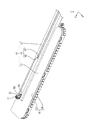
(レール12)
レール12は、金属製であって、各シート14に対して床上に一対設けられている。レール12を構成する金属としては、ステンレス、アルミニウム、アルミニウム合金等、必要に応じて任意の金属を適宜に使用できる。図1においては、一対のレール12のうち、右側に配されたレール12のみを図示している。レール12は、押出成形、ダイキャスト、曲げ加工、溶接等、公知の手法により形成することができる。
(Rail 12)
The
レール12は、前後方向に直線状に延びており、図4に示すように、スライダ13が挿通される挿通孔36が前後方向に貫通している。挿通孔36は、スライダ13の断面形状に応じた、略長方形状とされている。スライダ13は、挿通孔36内に、前後方向に摺動可能に配されている。
The
レール12は、前後方向に延びる底壁37と、底壁37の左右両側縁から上方に立ち上がる一対の側壁38と、側壁38の上端縁から左右方向の内方に延びた上壁39と、を有する。上壁39には、挿通孔36の上方の位置に、外部と連通する通し溝40が形成されている。側壁38は、下端部からやや上方の位置において、左右方向に拡開した形状をなしている。詳細には図示しないが、底壁37には、車両に固定するための固定手段が配されている。固定手段としては、例えば、ボルトが例示されるが、ボルトに限定されない。
The
(スライダ13)
スライダ13は、例えば、合成樹脂製又は金属製であって、レール12の挿通孔36内をスライド可能となっており、図4に示すように、挿通孔36に嵌め入れられる横長の挿通部41と、挿通部41の上面から板状に上方に突出する取付部42とを有する。
(Slider 13)
The
取付部42は、スライダ13の全長に亘って形成されており、例えばボルト等の公知の手段により、シート14と固定される。取付部42は、床上のマット等に形成された切り込みの間をスライド移動する。取付部42をシート14に固定することにより、シート14のスライドに伴ってスライダ13がレール12内を摺動する。
The mounting
(係合手段22)
図19に示すように、プロテクタ21と、ケース16とは、係合手段22により、着脱可能に係合されている。本実施形態に係る係合手段22は、ケース16の開口部30の孔縁部から後方に延びて形成された係合部43と、プロテクタ21の後端部であって、係合部43と対応する位置から前方に延びて形成された被係合部44である。
(Engagement means 22)
As shown in FIG. 19, the
図10に示すように、係合部43は、ケース16の開口部30の孔縁部のうち、右側縁に形成されている。なお、係合部43が開口部30の孔縁部に設けられているとは、係合部43が開口部30の孔縁部から連続して延びるように形成された場合を含むと共に、係合部43が開口部30の孔縁部に形成されていると実質的に認められる程度に近接して設けられている場合を含む。図11に示すように、係合部43は前後方向に延びる基壁45を有する。基壁45の壁面は、上下方向に沿って延びている。図10、図11、及び図12に示すように、基壁45の左側面には、上端縁、前端縁、及び下端縁から左方に突出すると共に、被係合部44の側縁を収容可能な溝部46が形成されている。基壁45と、溝部46との間に囲まれた空間内に、プロテクタ21の被係合部44の上端縁、前端縁、及び下端縁が挿入されるようになっている。基壁45のうち、左側面には、左方に突出する係合突起47が設けられている。基壁45のうち、右側面には、前後方向に延びると共に右方に突出する補強リブ48が設けられている。
As shown in FIG. 10, the engaging
図5及び図7に示すように、被係合部44は、プロテクタ21の後端部のうち、右側の側壁から前後方向に延びて形成されている。被係合部44は、左右方向に弾性変形可能な板状をなしている。被係合部44の右側面には、上下方向に延びる係合溝49が形成されている。この係合溝49に係合部43の係合突起47が後方から係合することにより、プロテクタ21がケース16に対して後方に移動することが規制されるようになっている。被係合部44の前端部は、上下方向について先細り形状をなしている。これにより、ケース16の係合部43に形成された溝部46に進入しやすくなっている。
As shown in FIGS. 5 and 7, the engaged
図9に示すように、ケース16とプロテクタ21とが係合した状態で、プロテクタ21の筒状部35は、レール12の前端部よりも後方に位置するようになっている。換言すると、少なくともプロテクタ21の筒状部35は、スライダ13がレール12上をスライド移動可能な領域内に位置している。
As shown in FIG. 9, the
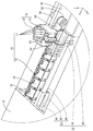
(仮係止部50)
プロテクタ21の筒状部35には、後端部から後方に突出する一対の仮係止部50が形成されている。仮係止部50は板面が上下方向に沿った板状をなしている。仮係止部50の後端部寄りの位置には、仮係止部50を左右方向に貫通するプロテクタ側貫通孔51が形成されている。一対の仮係止部50の左右方向の間隔は、スライダ13の取付部42の左右方向の幅寸法と同じか、やや大きく設定されている。これにより、一対の仮係止部50の間に、スライダ13の取付部42が進入できるようになっている。
(Temporary locking portion 50)
The
図15に示すように、スライダ13の取付部42が一対の仮係止部50の間に進入した状態で、スライダ13の取付部42には、プロテクタ側貫通孔51に対応する位置に、取付部42を貫通するスライダ側貫通孔52が形成されている。取付部42が一対の仮係止部50の間に進入した状態で、スライダ側貫通孔52と、プロテクタ側貫通孔51にボルト53が挿入され、このボルト53がナット54と螺合されることにより、プロテクタ21とスライダ13とが固定されるようになっている(図17参照)。
As shown in FIG. 15, in a state where the mounting
(組み付け工程)
続いて、本実施形態の組み付け工程の一例を説明する。組み付け工程は以下の記載に限定されない。
(Assembly process)
Subsequently, an example of the assembly process of this embodiment will be described. The assembly process is not limited to the following description.
電線17を外装体18の筒状のユニット19の内部に挿通させる。外装体18の一方の端部と、この端部から導出された電線17とを、第1部材31及び第2部材32で挟持することにより、外装体18の一方の端部にプロテクタ21を装着する。これにより、ワイヤーハーネス15が完成する。
The
アッパーケース27が組み付けられていない状態のロアケース26に、ワイヤーハーネス15を収容する。次に、アッパーケース27をロアケース26に組み付ける。このとき、ケース16の開口部30からワイヤーハーネス15の端部が導出されるようにする。
The
ケース16に設けられた係合部43に、後方から前方へと、プロテクタ21の被係合部44を接近させる。被係合部44の前端部のうち、上下両側縁が、係合部43の後端部の上下両側縁に形成された溝部46の内部に進入する。
The engaged
更に被係合部44を前方に移動させると、被係合部44の前端部が係合部43の係合突起47に乗り上げる。これにより、被係合部44は左方に弾性変形する。更に被係合部44を前方に移動させると、被係合部44が復帰変形し、係合部43の係合突起47が、被係合部44の係合溝49の内部に嵌り込む。これにより、係合部43と被係合部44とが前後方向に係合し、プロテクタ21がケース16に対して後方に移動することが規制される。これにより、ワイヤーハーネス配索装置11が完成する(図9参照)。
Further, when the engaged
レール12を所定の形状に加工し、レール12の挿通孔36内にスライダ13の挿通部41を挿通させると共に、レール12の通し溝40内にスライダ13の取付部42を配置する。これにより、レール12に対して前後方向にスライド可能な状態で、スライダ13がレール12に組み付けられる。
The
図13に示すように、ワイヤーハーネス配索装置11と、スライダ13が組み付けられたレール12と、を車両の所定の位置に固定する。このとき、ケース16の開口部30と、レール12の前端部と、が対向するように配置する。
As shown in FIG. 13, the wire
図14、及び図15に示すように、スライダ13を前方に移動させる。レール12の前端部までスライダ13を移動させると、スライダ13の取付部42が、プロテクタ21に設けられた一対の仮係止部50の間に進入する。これにより、スライダ13とプロテクタ21とが仮係止される。この状態で、プロテクタ側貫通孔51と、スライダ側貫通孔52とに、ボルト53を挿通し、ボルト53の軸部をナット54に螺合させることにより、プロテクタ21とスライダ13とを固定する(図16及び図17参照)。
As shown in FIGS. 14 and 15, the
続いて、スライダ13を後方に引っ張る。すると、スライダ13に固定されたプロテクタ21も後方に引っ張られる。この結果、ケース16に設けられた係合部43の係合突起47が、プロテクタ21の被係合部44に設けられた係合溝49の前壁に後方から当接する。更にスライダ13を後方に引っ張ると、被係合部44も追従して後方に引っ張られ、被係合部44が係合突起47に乗り上げて、被係合部44が右方に弾性変形する。更にスライダ13を後方に引っ張ることにより、被係合部44が係合突起47を乗り越えて復帰変形し、係合部43と被係合部44との係合が解除される。これにより、スライダ13は前後方向にスライド可能となる(図18参照)。このスライダ13に固定されたプロテクタ21にはワイヤーハーネス15が取り付けられているので、スライダ13の前後移動に伴って、ワイヤーハーネス15が前後方向の力を受け、ケース16の開口部30から後方へ導出され、又は、開口部30からケース16の内方へ導入される。これにより、スライド配線装置10が完成する。
Subsequently, the
(本実施形態の作用、効果)
続いて、本実施形態の作用、効果について説明する。本実施形態に係るワイヤーハーネス配索装置11は、ワイヤーハーネス15と、ワイヤーハーネス15が収容されると共に、開口部30を有して開口部30からワイヤーハーネス15を導出又は導入可能であるケース16と、開口部30から導出されたワイヤーハーネス15に取り付けられたプロテクタ21と、ケース16とプロテクタ21とを着脱可能に係合する係合手段22と、を備える。
(Action and effect of this embodiment)
Subsequently, the actions and effects of this embodiment will be described. The wire
本実施形態によれば、ケース16の開口部30から導出されたワイヤーハーネス15を、ケース16に係合させることができる。これにより、ワイヤーハーネス配索装置11を輸送する際に、ケース16の開口部30から導出されたワイヤーハーネス15は、振動等を受けた場合でも揺れ動かないようになっている。これにより、ワイヤーハーネス15が異物と衝突することを抑制することができる。
According to the present embodiment, the
また、本実施形態によれば、係合手段22は、ケース16に設けられた係合部43と、プロテクタ21に設けられた被係合部44である。これにより、係合手段22が、ケース16及びプロテクタ21と異なる部材で構成される場合に比べて、部品点数を少なくすることができる。
Further, according to the present embodiment, the engaging
本実施形態によれば、係合部43は、開口部30の孔縁部に設けられている。
According to the present embodiment, the engaging
上記の構成によれば、ケース16から引き出された状態のワイヤーハーネス15を、開口部30からケース16内に押し込んでいくことにより、プロテクタ21はケース16の開口部30へと近付いていく。この開口部30の孔縁部に、プロテクタ21の被係合部44と係合する係合部43が設けられているので、ワイヤーハーネス15をケース16内へ押し込む動作と、開口部30の孔縁部に形成された係合部43へプロテクタ21を接近させる動作とを同時に行うことができる。この結果、プロテクタ21とケース16との間の位置決めを容易に行うことができる。
According to the above configuration, the
また、本実施形態によれば、係合手段22によるケース16とプロテクタ21との係合が解除される方向は、開口部30からワイヤーハーネス15が導出される方向に平行である。これにより、開口部30からワイヤーハーネス15が導出される方向に沿ってワイハーハーネスを引っ張ることにより、ケース16とプロテクタ21との係合を解除することができる。この結果、ワイヤーハーネス15を引っ張るという簡易な手法により、ケース16とプロテクタ21との係合を解除することができる。
Further, according to the present embodiment, the direction in which the
本実施形態に係るスライド配線装置10は、ワイヤーハーネス配索装置11と、ケース16の開口部30に一方の端部が配されると共に、開口部30からワイヤーハーネス15が導出される方向に沿って延びるレール12と、レール12に対してスライド可能に配されると共に、プロテクタ21と固定されたスライダ13と、を備えている。このように、ワイヤーハーネス配索装置11を、スライド配線装置10に適用することができる。
In the
また、スライダ13をスライド移動させることにより、スライダ13に固定されたプロテクタ21も移動させることができる。この結果、開口部30からワイヤーハーネス15が導出される方向に沿ってスライダ13を移動させることにより、スライダ13に固定されたプロテクタ21を介して、ワイハーハーネスを引っ張ることができる。これにより、ケース16とプロテクタ21との係合を解除することができる。このように、スライダ13をスライドさせるという簡易な手法により、ケース16とプロテクタ21との係合を解除することができる。
Further, by sliding the
また、本実施形態によれば、プロテクタ21とケース16とが係合した状態で、プロテクタ21の少なくとも一部は、スライダ13がスライド移動可能な領域内に位置しており、プロテクタ21及びスライダ13の一方は、他方と仮係止する仮係止部50を有している。
Further, according to the present embodiment, with the
スライダ13がレール12に配された状態で、スライダ13とプロテクタ21との組み付け作業を行う場合、レール12の内側の領域で組み付け作業を行う必要が生じる場合がある。この場合、レール12の内側という狭い空間内での作業となってしまうため、作業効率が低下する。これを避けるために、一旦、スライダ13をレール12から外した後に、スライダ13とプロテクタ21との組み付け作業を行い、再びスライダ13をレール12に取り付けることが考えられるが、作業が煩雑となる。
When assembling the
本実施形態によれば、プロテクタ21がケース16に係合された状態で、スライダ13をスライド移動させることにより、プロテクタ21とスライダ13とを仮係止することができる。これにより、プロテクタ21とスライダ13とを仮係止した状態で、プロテクタ21とスライダ13とを固定することができるので、プロテクタ21とスライダ13との固定作業の効率を向上させることができる。
According to the present embodiment, the
<他の実施形態>
本明細書に開示された技術は上記記述及び図面によって説明した実施形態に限定されるものではなく、例えば次のような実施形態も本明細書に開示された技術の技術的範囲に含まれる。
<Other embodiments>
The techniques disclosed herein are not limited to the embodiments described above and in the drawings, and for example, the following embodiments are also included in the technical scope of the techniques disclosed herein.
(1)本実施形態では、係合手段22は、ケース16に設けられた係合部43と、プロテクタ21に設けられた被係合部44としたが、これに限られず、係合手段22は、例えば、クリップのように、ケース16及びプロテクタ21とは別体の部材であって、ケース16及びプロテクタ21を重ねた状態で挟持することにより互いに係合させる構成としてもよい。
(1) In the present embodiment, the engaging
(2)本実施形態では、ケース16に設けられた係合部43が、電線17がケース16から導出される方向に沿って延出される構成としたが、これに限られず、プロテクタ21に設けられた被係合部44が、電線17がケース16から導出される方向に沿って延出されている形態としてもよい。
In (2) In the present embodiment, the engaging
(3)本実施形態においては、係合手段22によるケース16とプロテクタ21との係合が解除される方向は、開口部30から電線17が導出される方向に平行であったが、これに限られず、例えば、係合手段22がクリップの場合のように、開口部30から電線17が導出される方向と交差する方向に沿ってクリップをケース16及びプロテクタ21から離脱させる構成としてもよい。
(3) In the present embodiment, the direction in which the
(4)プロテクタ21とスライダ13とを仮係止する仮係止部50は省略してもよい。
(4) The
(5)本実施形態においては、スライダ13にはシート14が取り付けられる構成としたが、これに限られず、スライダ13には、スライドドア等、レール12に対してスライドする任意の部材が取り付けられる構成としてもよい。
(5) In the present embodiment, the
(6)本実施形態では、ワイヤーハーネス15は4つの電線17を含む構成としたが、これに限られず、ワイヤーハーネス15は、2つ〜3つ、又は、5つ以上の電線17を含む構成としてもよい。
(6) In the present embodiment, the
10: スライド配線装置
11: ワイヤーハーネス配索装置
12: レール
13: スライダ
15: ワイヤーハーネス
16: ケース
18: 外装体
21: プロテクタ
22: 係合手段
30: 開口部
43: 係合部
44: 被係合部
50: 仮係止部
51: プロテクタ側貫通孔
51: プロテクタ側貫通孔
52: スライダ側貫通孔
10: Slide wiring device 11: Wire harness wiring device 12: Rail 13: Slider 15: Wire harness 16: Case 18: Exterior body 21: Protector 22: Engagement means 30: Opening 43: Engagement portion 44: Engagement Joint portion 50: Temporary locking portion 51: Protector side through hole 51: Protector side through hole 52: Slider side through hole
Claims (6)
前記ワイヤーハーネスが収容されると共に、開口部を有して前記開口部から前記ワイヤーハーネスを導出又は導入可能であるケースと、
前記開口部から導出された前記ワイヤーハーネスに取り付けられたプロテクタと、
前記ケースと前記プロテクタとを着脱可能に係合する係合手段と、
を備えたワイヤーハーネス配索装置。 With a wire harness
A case in which the wire harness is housed and has an opening so that the wire harness can be derived or introduced from the opening.
A protector attached to the wire harness derived from the opening and
An engaging means that detachably engages the case and the protector,
Wire harness routing device equipped with.
前記ケースの前記開口部に一方の端部が配されると共に、前記開口部から前記ワイヤーハーネスが導出される方向に沿って延びるレールと、
前記レールに対してスライド可能に配されると共に、前記プロテクタと固定されたスライダと、を備えたスライド配線装置。 The wire harness routing device according to any one of claims 1 to 4.
A rail that has one end arranged in the opening of the case and extends along a direction in which the wire harness is led out from the opening.
A slide wiring device that is slidably arranged with respect to the rail and includes the protector and a fixed slider.
前記プロテクタ及び前記スライダの一方は、他方と仮係止する仮係止部を有している、請求項5に記載のスライド配線装置。 With the protector engaged to the case, at least a portion of the protector is located within a slidable area of the slider.
The slide wiring device according to claim 5, wherein one of the protector and the slider has a temporary locking portion that temporarily locks the other.
Priority Applications (5)
| Application Number | Priority Date | Filing Date | Title |
|---|---|---|---|
| JP2017152205A JP6760228B2 (en) | 2017-08-07 | 2017-08-07 | Wire harness wiring device and slide wiring device |
| CN201880048217.6A CN110959238B (en) | 2017-08-07 | 2018-07-26 | Wire harness routing device and sliding routing device |
| PCT/JP2018/028024 WO2019031254A1 (en) | 2017-08-07 | 2018-07-26 | Wire harness routing device and slide wiring device |
| US16/636,663 US11203308B2 (en) | 2017-08-07 | 2018-07-26 | Wire harness routing device and slide wiring device |
| DE112018004013.5T DE112018004013T5 (en) | 2017-08-07 | 2018-07-26 | Cable harness guiding device and sliding wiring device |
Applications Claiming Priority (1)
| Application Number | Priority Date | Filing Date | Title |
|---|---|---|---|
| JP2017152205A JP6760228B2 (en) | 2017-08-07 | 2017-08-07 | Wire harness wiring device and slide wiring device |
Publications (3)
| Publication Number | Publication Date |
|---|---|
| JP2019033570A JP2019033570A (en) | 2019-02-28 |
| JP2019033570A5 JP2019033570A5 (en) | 2019-12-26 |
| JP6760228B2 true JP6760228B2 (en) | 2020-09-23 |
Family
ID=65271164
Family Applications (1)
| Application Number | Title | Priority Date | Filing Date |
|---|---|---|---|
| JP2017152205A Active JP6760228B2 (en) | 2017-08-07 | 2017-08-07 | Wire harness wiring device and slide wiring device |
Country Status (5)
| Country | Link |
|---|---|
| US (1) | US11203308B2 (en) |
| JP (1) | JP6760228B2 (en) |
| CN (1) | CN110959238B (en) |
| DE (1) | DE112018004013T5 (en) |
| WO (1) | WO2019031254A1 (en) |
Families Citing this family (2)
| Publication number | Priority date | Publication date | Assignee | Title |
|---|---|---|---|---|
| FR3114057B1 (en) * | 2020-09-15 | 2022-12-02 | Faurecia Sieges Dautomobile | Electrical cable guide device for motor vehicle seat rail |
| KR20220060244A (en) * | 2020-11-04 | 2022-05-11 | 현대자동차주식회사 | Seat rail for vehicle |
Family Cites Families (14)
| Publication number | Priority date | Publication date | Assignee | Title |
|---|---|---|---|---|
| US7000967B2 (en) * | 2002-12-27 | 2006-02-21 | Ts Tech Co., Ltd. | Slidable vehicle seat provided with automotive electronic parts |
| JP4095940B2 (en) * | 2003-08-13 | 2008-06-04 | 矢崎総業株式会社 | Power supply device for slide sheet |
| US7730669B2 (en) * | 2003-09-22 | 2010-06-08 | Sumitomo Wiring Systems, Ltd. | Device for guiding a conductor path for slide door |
| JP4263684B2 (en) * | 2004-08-06 | 2009-05-13 | 矢崎総業株式会社 | Power supply device for slide |
| JP4403091B2 (en) * | 2005-03-03 | 2010-01-20 | 矢崎総業株式会社 | Power supply device |
| JP2009194990A (en) * | 2008-02-13 | 2009-08-27 | Yazaki Corp | Electric supply device for slide structure |
| US9308833B2 (en) * | 2008-12-16 | 2016-04-12 | Yazaki Corporation | Harness wiring apparatus |
| JP5356937B2 (en) * | 2009-07-22 | 2013-12-04 | 矢崎総業株式会社 | Wire harness wiring device |
| JP5248436B2 (en) * | 2009-07-22 | 2013-07-31 | 矢崎総業株式会社 | Wire harness wiring device |
| JP2012045994A (en) | 2010-08-25 | 2012-03-08 | Sumitomo Wiring Syst Ltd | Slide wiring device |
| JP5800608B2 (en) * | 2011-02-23 | 2015-10-28 | 矢崎総業株式会社 | Harness wiring device |
| JP6390906B2 (en) * | 2014-12-03 | 2018-09-19 | 株式会社オートネットワーク技術研究所 | Wire harness mounting structure and wiring unit |
| JP6168110B2 (en) * | 2015-07-07 | 2017-07-26 | 住友電装株式会社 | Wire harness wiring device for slide sheet |
| JP6436039B2 (en) | 2015-10-01 | 2018-12-12 | 株式会社オートネットワーク技術研究所 | Slide wiring device |
-
2017
- 2017-08-07 JP JP2017152205A patent/JP6760228B2/en active Active
-
2018
- 2018-07-26 US US16/636,663 patent/US11203308B2/en active Active
- 2018-07-26 WO PCT/JP2018/028024 patent/WO2019031254A1/en active Application Filing
- 2018-07-26 CN CN201880048217.6A patent/CN110959238B/en active Active
- 2018-07-26 DE DE112018004013.5T patent/DE112018004013T5/en active Pending
Also Published As
| Publication number | Publication date |
|---|---|
| DE112018004013T5 (en) | 2020-05-07 |
| CN110959238A (en) | 2020-04-03 |
| WO2019031254A1 (en) | 2019-02-14 |
| JP2019033570A (en) | 2019-02-28 |
| CN110959238B (en) | 2021-08-20 |
| US20210146864A1 (en) | 2021-05-20 |
| US11203308B2 (en) | 2021-12-21 |
Similar Documents
| Publication | Publication Date | Title |
|---|---|---|
| JP6436039B2 (en) | Slide wiring device | |
| EP2267855B1 (en) | Partitioned electrical junction box | |
| US20050112940A1 (en) | Apparatus equipped with electronic control units | |
| JP6760228B2 (en) | Wire harness wiring device and slide wiring device | |
| CN108242790B (en) | Electrical connection box and wire harness | |
| US10807544B2 (en) | Wire harness routing device | |
| US10836332B2 (en) | Connection structure connecting conduit to protector, and wire harness | |
| JP2015071333A (en) | Wire harness module for door | |
| JP6610403B2 (en) | Wire harness wiring device | |
| JP2017093016A (en) | Wire harness routing device | |
| JP2011234495A (en) | Electrical connection box | |
| CN109565162B (en) | Vehicle-mounted component | |
| JP6056732B2 (en) | Wire harness routing device for slide sheet | |
| JP2007112187A (en) | Mounting structure of wiring harness | |
| JP2019033570A5 (en) | ||
| JP2017093015A (en) | Wire harness routing device | |
| WO2020012882A1 (en) | Wiring device and slide wiring device | |
| JP6919991B2 (en) | Harness protector | |
| JP5939200B2 (en) | Connecting structure of slide sheet and slider | |
| JP2017095031A (en) | Wire harness routing device | |
| JP5003144B2 (en) | Connector holding structure | |
| JP2019030168A (en) | Wiring harness laying device | |
| JP2012091530A (en) | Wiring structure of harness for automobile | |
| JP2006168582A (en) | Mounting structure of decorative member and slide wiring device using it | |
| JP2010184602A (en) | Luggage trim |
Legal Events
| Date | Code | Title | Description |
|---|---|---|---|
| A521 | Written amendment |
Free format text: JAPANESE INTERMEDIATE CODE: A523 Effective date: 20191113 |
|
| A621 | Written request for application examination |
Free format text: JAPANESE INTERMEDIATE CODE: A621 Effective date: 20191129 |
|
| TRDD | Decision of grant or rejection written | ||
| A01 | Written decision to grant a patent or to grant a registration (utility model) |
Free format text: JAPANESE INTERMEDIATE CODE: A01 Effective date: 20200804 |
|
| A61 | First payment of annual fees (during grant procedure) |
Free format text: JAPANESE INTERMEDIATE CODE: A61 Effective date: 20200817 |
|
| R150 | Certificate of patent or registration of utility model |
Ref document number: 6760228 Country of ref document: JP Free format text: JAPANESE INTERMEDIATE CODE: R150 |