CN110959238B - Wire harness routing device and sliding routing device - Google Patents
Wire harness routing device and sliding routing device Download PDFInfo
- Publication number
- CN110959238B CN110959238B CN201880048217.6A CN201880048217A CN110959238B CN 110959238 B CN110959238 B CN 110959238B CN 201880048217 A CN201880048217 A CN 201880048217A CN 110959238 B CN110959238 B CN 110959238B
- Authority
- CN
- China
- Prior art keywords
- protector
- wire harness
- case
- opening
- slider
- Prior art date
- Legal status (The legal status is an assumption and is not a legal conclusion. Google has not performed a legal analysis and makes no representation as to the accuracy of the status listed.)
- Active
Links
Images


Classifications
-
- B—PERFORMING OPERATIONS; TRANSPORTING
- B60—VEHICLES IN GENERAL
- B60R—VEHICLES, VEHICLE FITTINGS, OR VEHICLE PARTS, NOT OTHERWISE PROVIDED FOR
- B60R16/00—Electric or fluid circuits specially adapted for vehicles and not otherwise provided for; Arrangement of elements of electric or fluid circuits specially adapted for vehicles and not otherwise provided for
- B60R16/02—Electric or fluid circuits specially adapted for vehicles and not otherwise provided for; Arrangement of elements of electric or fluid circuits specially adapted for vehicles and not otherwise provided for electric constitutive elements
- B60R16/0207—Wire harnesses
- B60R16/0215—Protecting, fastening and routing means therefor
-
- B—PERFORMING OPERATIONS; TRANSPORTING
- B60—VEHICLES IN GENERAL
- B60R—VEHICLES, VEHICLE FITTINGS, OR VEHICLE PARTS, NOT OTHERWISE PROVIDED FOR
- B60R16/00—Electric or fluid circuits specially adapted for vehicles and not otherwise provided for; Arrangement of elements of electric or fluid circuits specially adapted for vehicles and not otherwise provided for
- B60R16/02—Electric or fluid circuits specially adapted for vehicles and not otherwise provided for; Arrangement of elements of electric or fluid circuits specially adapted for vehicles and not otherwise provided for electric constitutive elements
- B60R16/023—Electric or fluid circuits specially adapted for vehicles and not otherwise provided for; Arrangement of elements of electric or fluid circuits specially adapted for vehicles and not otherwise provided for electric constitutive elements for transmission of signals between vehicle parts or subsystems
- B60R16/027—Electric or fluid circuits specially adapted for vehicles and not otherwise provided for; Arrangement of elements of electric or fluid circuits specially adapted for vehicles and not otherwise provided for electric constitutive elements for transmission of signals between vehicle parts or subsystems between relatively movable parts of the vehicle, e.g. between steering wheel and column
-
- B—PERFORMING OPERATIONS; TRANSPORTING
- B60—VEHICLES IN GENERAL
- B60N—SEATS SPECIALLY ADAPTED FOR VEHICLES; VEHICLE PASSENGER ACCOMMODATION NOT OTHERWISE PROVIDED FOR
- B60N2/00—Seats specially adapted for vehicles; Arrangement or mounting of seats in vehicles
- B60N2/02—Seats specially adapted for vehicles; Arrangement or mounting of seats in vehicles the seat or part thereof being movable, e.g. adjustable
- B60N2/04—Seats specially adapted for vehicles; Arrangement or mounting of seats in vehicles the seat or part thereof being movable, e.g. adjustable the whole seat being movable
- B60N2/06—Seats specially adapted for vehicles; Arrangement or mounting of seats in vehicles the seat or part thereof being movable, e.g. adjustable the whole seat being movable slidable
- B60N2/07—Slide construction
- B60N2/0722—Constructive details
-
- H—ELECTRICITY
- H02—GENERATION; CONVERSION OR DISTRIBUTION OF ELECTRIC POWER
- H02G—INSTALLATION OF ELECTRIC CABLES OR LINES, OR OF COMBINED OPTICAL AND ELECTRIC CABLES OR LINES
- H02G11/00—Arrangements of electric cables or lines between relatively-movable parts
- H02G11/006—Arrangements of electric cables or lines between relatively-movable parts using extensible carrier for the cable, e.g. self-coiling spring
-
- H—ELECTRICITY
- H02—GENERATION; CONVERSION OR DISTRIBUTION OF ELECTRIC POWER
- H02G—INSTALLATION OF ELECTRIC CABLES OR LINES, OR OF COMBINED OPTICAL AND ELECTRIC CABLES OR LINES
- H02G3/00—Installations of electric cables or lines or protective tubing therefor in or on buildings, equivalent structures or vehicles
- H02G3/02—Details
- H02G3/04—Protective tubing or conduits, e.g. cable ladders or cable troughs
- H02G3/0462—Tubings, i.e. having a closed section
- H02G3/0475—Tubings, i.e. having a closed section formed by a succession of articulated units
-
- H—ELECTRICITY
- H02—GENERATION; CONVERSION OR DISTRIBUTION OF ELECTRIC POWER
- H02G—INSTALLATION OF ELECTRIC CABLES OR LINES, OR OF COMBINED OPTICAL AND ELECTRIC CABLES OR LINES
- H02G3/00—Installations of electric cables or lines or protective tubing therefor in or on buildings, equivalent structures or vehicles
- H02G3/02—Details
- H02G3/04—Protective tubing or conduits, e.g. cable ladders or cable troughs
- H02G3/0462—Tubings, i.e. having a closed section
Abstract
A wire harness routing device (11) is provided with: a wire harness (15); a case (16) that houses the wire harness (15), has an opening (30), and can guide the wire harness (15) out of or into the case through the opening (30); a protector (21) attached to the wire harness (15) led out from the opening (30); and an engaging structure (22) for detachably engaging the case (16) and the protector (21).
Description
Technical Field
The technology disclosed in this specification relates to a wire harness routing device and a slide routing device using the same.
Background
Conventionally, as a harness routing device that electrically connects a vehicle and a slide member such as a slide seat mounted on the vehicle, a harness routing device described in japanese patent application laid-open No. 2012-45994 is known. The wire harness routing device is provided with: a track; a slider slidably attached to the rail; a wire harness disposed in the rail and having one end connected to the slider; and a harness storage section that stores a harness led out from the rail.
Documents of the prior art
Patent document
Patent document 1: japanese patent laid-open publication No. 2012-45994
Disclosure of Invention
Problems to be solved by the invention
In the above-described wire harness routing device, the rail to which the slider is attached and the wire harness housing portion housing the wire harness are manufactured at different places, and then the rail and the wire harness housing portion are assembled at a place where the two members are assembled. Examples of the place where the above-described members are manufactured or assembled include a different place in one factory, a plurality of different factories, and the like.
In a state before the rail and the harness storage portion are assembled, the harness is led out from the harness storage portion. A protector member and a connector are attached to the led-out wire harness. Therefore, when the wire harness housing portion is transported to a place where assembly is performed, the wire harness, the protector member, and the connector led out from the wire harness housing portion may shake due to vibration during transportation and come into contact with foreign matter, which may cause a problem.
The technology disclosed in the present specification has been completed based on the above-described circumstances, and an object thereof is to provide a wire harness routing device that can suppress contact with foreign matter during transportation.
Means for solving the problems
The technology disclosed in this specification is a wire harness routing device including: a wire harness; a case that houses the wire harness, has an opening, and can guide the wire harness out of or into the case from the opening; a protector attached to the wire harness led out from the opening; and an engaging structure for detachably engaging the case and the protector.
According to the above configuration, the wire harness led out from the opening of the case can be engaged with the case. Thus, when the harness routing device is conveyed, the harness led out from the opening of the box body does not shake even when vibration or the like is applied. This can prevent the wire harness from colliding with foreign matter.
As an embodiment of the technology disclosed in the present specification, the following is preferable.
The clamping structure is arranged on the clamping part of the box body and the clamped part of the protector.
According to the above configuration, the number of components can be reduced as compared with a case where the engagement structure is formed of a member different from the case and the protector.
Preferably, the engaging portion is provided at an edge of the opening.
According to the above configuration, the protector approaches the opening of the case by pushing the harness drawn out from the harness storage into the harness storage through the opening. Since the engagement portion that engages with the engaged portion of the protector is provided at the hole edge portion of the opening, the operation of pushing the wire harness into the wire harness storage portion and the operation of bringing the protector close to the engagement portion formed at the hole edge portion of the opening can be performed simultaneously, and therefore, the positioning between the protector and the case can be easily performed.
Preferably, a direction in which the engagement of the case and the protector by the engagement structure is released is parallel to a direction in which the wire harness is led out from the opening.
According to the above configuration, the engagement between the case and the protector can be released by pulling the wire harness in the direction in which the wire harness is led out from the opening. Thus, the engagement between the case and the protector can be released by a simple method of pulling the wire harness.
The technology disclosed in the present specification is a sliding wiring device including: a harness routing device; a rail, one end of which is disposed at the opening of the case and extends in a direction in which the wire harness is led out from the opening; and a slider which is disposed on the rail so as to be slidable relative to the rail and is fixed to the protector.
According to the above configuration, the wire harness routing device can be applied to a slide routing device.
Further, by sliding the slider, the protector fixed to the slider can also be moved. As a result, the harness can be pulled by the protector fixed to the slider by moving the slider in the direction in which the harness is led out from the opening portion. Thus, the engagement between the case and the protector can be released. Thus, the engagement between the case and the protector can be released by a simple method of sliding the slider.
Preferably, in a state where the protector and the case are engaged, at least a part of the protector is located in a region where the slider is slidable, and one of the protector and the slider has a temporary locking portion that temporarily locks the other.
When the assembly work of the slider and the protector is performed in a state where the slider is disposed on the rail, the assembly work may be required to be performed in an inner region of the rail. In this case, since the work is performed in a narrow space such as the inner side of the rail, the work efficiency is lowered. To avoid this, consider the following: after the slider is once detached from the rail, the slider and the protector are assembled to each other, and the slider is again attached to the rail.
According to the above configuration, the protector and the slider can be temporarily locked by sliding the slider in a state where the protector is engaged with the case. Thus, the protector and the slider can be fixed in a state where the protector and the slider are temporarily locked, and therefore, the efficiency of the fixing operation of the protector and the slider can be improved.
Effects of the invention
According to the technique disclosed in the present specification, the wire harness led out from the wire harness routing device can be suppressed from coming into contact with foreign matter.
Drawings
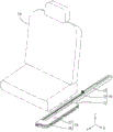
Fig. 1 is a perspective view showing a slide wiring device according to embodiment 1.
Fig. 2 is a perspective view showing the slide wiring device.
Fig. 3 is a bottom view showing the slide wiring device.
Fig. 4 is a rear view showing the slide wiring device.
Fig. 5 is a perspective view showing a state in which the protector and the exterior body are assembled.
Fig. 6 is a left side view showing a state where the protector and the exterior body are assembled.
Fig. 7 is a right side view showing a state where the protector and the exterior body are assembled.
Fig. 8 is a perspective view showing a state where the cartridge and the rail are assembled to a predetermined position.
Fig. 9 is a partially enlarged perspective view showing the wire harness routing device.
Fig. 10 is a cross-sectional view taken along line X-X in fig. 8.
Fig. 11 is a cross-sectional view taken along line XI-XI in fig. 8.
Fig. 12 is a sectional view taken along line XII-XII in fig. 11.
Fig. 13 is a perspective view showing a state before the slider and the protector are temporarily locked in the assembly process of the slide wiring device.
Fig. 14 is a perspective view showing a state in which the slider and the protector are temporarily locked in the assembly process of the slide wiring device.
Fig. 15 is a partially enlarged perspective view showing a state where the slider and the protector are temporarily locked in the assembly process of the slide wiring device.
Fig. 16 is a perspective view showing a state in which the slider and the protector are fixed in the assembly process of the slide wiring device.
Fig. 17 is a partially enlarged perspective view showing a state in which the slider and the protector are fixed in the assembly process of the slide wiring device.
Fig. 18 is a perspective view showing a state where engagement between the case and the protector is released in the assembly process of the slide wiring device.
Fig. 19 is a partially enlarged perspective view showing a state where engagement between the case and the protector is released in the assembly process of the slide wiring device.
Detailed Description
< embodiment 1>
Embodiment 1 of the technology disclosed in the present specification will be described with reference to fig. 1 to 19. The slide wiring device 10 of the present embodiment includes a harness routing device 11, a rail 12, and a slider 13. The slide wiring device 10 of the present embodiment is a device for routing a wire harness 15 between a vehicle body (not shown) of a vehicle (not shown) such as an automobile and a seat 14. Hereinafter, the X direction of fig. 1 is referred to as the right direction, the Y direction is referred to as the front direction, and the Z direction is referred to as the upper direction. In some cases, only one member is denoted by a reference numeral, and the other members are not denoted by the reference numeral.
As shown in fig. 1, the seat 14 is slidable in the front-rear direction with respect to the metal rails 12, and the rails 12 are fixed to the floor of the passenger compartment of the vehicle body by bolting or the like. The seat 14 includes various electrical components such as an electric automatic adjustment device, a seat heater, a sensor for detecting whether or not a passenger is seated, and a sensor for detecting whether or not a seat belt is buckled. Although not shown in detail, the seat 14 is attached to the slider 13, and the slider 13 is slidably disposed on the rail 12.
(Wiring harness 15)
The wire harness 15 is arranged on the floor (under a carpet, a panel, or the like) or under the floor of the vehicle body, and is connected to a device such as an ECU (Electronic Control Unit) on the vehicle body side. Power supply and signal transmission and reception between the equipment on the vehicle body side and the electrical components of the seat 14 are performed through the wire harness 15.
As shown in fig. 2, a wire harness 15 arranged between the seat 14 and the vehicle body is inserted through the rail 12 and the box 16 under the seat 14. The wire harness 15 includes a plurality of (four in the present embodiment) electric wires 17 and an exterior body 18 covering the plurality of electric wires 17. Each wire 17 is connected to various electrical components provided in the seat 14, with a metal conductor portion covered with an insulating layer.
The outer case 18 is made of insulating synthetic resin, covers the electric wires 17, and extends in a band shape. In other words, the exterior body 18 is externally fitted to the plurality of electric wires 17. The exterior body 18 is formed by connecting a plurality of cylindrical units 19 by hinges 20 formed integrally with the units 19. The exterior body 18 is formed to be bendable at the hinge 20.
(harness routing device 11)
The wire harness routing device 11 includes: a wire harness 15; a case 16 that houses the wire harness 15; a protector 21 attached to the wire harness 15 led out from the case 16; and an engaging structure 22 for detachably engaging the case 16 and the protector 21.
The material forming the case 16 may be appropriately selected from synthetic resin, metal, and the like as needed. As shown in fig. 3, the case 16 is provided with a bracket 23. The case 16 is fixed to the vehicle body by inserting bolts (not shown) into the through-holes 24 penetrating the brackets 23 and screwing the bolts to the vehicle body.
As shown in fig. 2, the case 16 is elongated in the front-rear direction and slightly protrudes to the left from the front end, and has a substantially J-shape when viewed from above.
The cartridge 16 includes: a lower case 26 opened at the top; and an upper case 27 assembled to the lower case 26 from above to cover the lower case 26. The upper case 27 has substantially the same shape as the opening portion of the upper end edge of the lower case 26. Lower case 26 and upper case 27 are integrally assembled by elastically locking claw 28 formed on the side wall of upper case 27 and locking piece 29 formed on the side wall of lower case 26.
As shown in fig. 10, an opening 30 that opens rearward is formed at a rear end portion of a portion of lower case 26, the front end portion of which protrudes leftward, and at a position closer to the left. Harness 15 is led out of case 16 through opening 30 or led into case 16. The cross-sectional shape of the opening 30 is formed larger than the cross-sectional shape of the exterior body 18, so that the exterior body 18 can be easily inserted through the opening 30.
As shown in fig. 5, 6 and 7, the electric wire 17 externally mounted by the external body 18 is led out rearward from the opening 30. A protector 21 made of synthetic resin is disposed at the rear end of the outer case 18. The 1 st and 2 nd separable members 31 and 32 of the protector 21 are assembled integrally by elastically engaging a lock portion 33 formed on one side and a lock receiving portion 34 formed on the other side. The end of the outer package 18 is sandwiched between the 1 st member 31 and the 2 nd member 32, whereby the outer package 18 and the protector 21 are integrally assembled.
The protector 21 has a cylindrical portion 35 extending upward and opening upward. The electric wire 17 led out from the outer package 18 is led out upward from the upper end of the cylindrical portion 35.
(Rail 12)
The rails 12 are made of metal, and a pair is provided on the floor for each seat 14. As the metal constituting the rail 12, any metal such as stainless steel, aluminum alloy, or the like can be suitably used as necessary. In fig. 1, only the rail 12 disposed on the right side of the pair of rails 12 is shown. The rail 12 can be formed by a known method such as extrusion, die casting, bending, or welding.
The rail 12 extends linearly in the front-rear direction, and as shown in fig. 4, an insertion hole 36 through which the slider 13 is inserted is formed in the front-rear direction. The insertion hole 36 is formed in a substantially rectangular shape corresponding to the cross-sectional shape of the slider 13. The slider 13 is disposed in the insertion hole 36 so as to be slidable in the front-rear direction.
The rail 12 has: a bottom wall 37 extending in the front-rear direction; a pair of side walls 38 rising upward from both left and right side edges of the bottom wall 37; and an upper wall 39 extending inward in the left-right direction from the upper end edge of the side wall 38. A through groove 40 communicating with the outside is formed in the upper wall 39 at a position above the insertion hole 36. The side wall 38 is formed to expand in the left-right direction from a position slightly above the lower end portion. Although not shown in detail, a fixing structure for fixing to the vehicle is disposed on the bottom wall 37. As the fixing structure, for example, a bolt can be exemplified, but not limited to a bolt.
(sliding member 13)
The slider 13 is made of, for example, synthetic resin or metal, is slidable in the insertion hole 36 of the rail 12, and includes, as shown in fig. 4: a laterally long insertion portion 41 that is fitted into the insertion hole 36; and a mounting portion 42 that protrudes upward in a plate shape from the upper surface of the insertion portion 41.
The mounting portion 42 is formed over the entire length of the slider 13, and is fixed to the seat 14 by a known structure such as a bolt. The mounting portion 42 slidably moves between cutouts of a carpet or the like formed on the floor. By fixing the mounting portion 42 to the seat 14, the slider 13 slides in the rail 12 in accordance with the sliding of the seat 14.
(engaging structure 22)
As shown in fig. 19, the protector 21 and the case 16 are detachably engaged by an engagement structure 22. The engaging structure 22 of the present embodiment is an engaging portion 43 formed to extend rearward from a hole edge portion of the opening portion 30 of the case 16, and an engaged portion 44 formed to extend forward from a rear end portion of the protector 21 at a position corresponding to the engaging portion 43.
As shown in fig. 10, the engaging portion 43 is formed on the right edge of the hole edge portion of the opening 30 of the case 16. The engagement portion 43 is provided at the hole edge portion of the opening portion 30, and includes a case where the engagement portion 43 is formed to extend continuously from the hole edge portion of the opening portion 30, and includes a case where the engagement portion 43 is provided so as to be close to a degree that the engagement portion 43 can be basically considered to be formed at the hole edge portion of the opening portion 30. As shown in fig. 11, the engaging portion 43 has a base wall 45 extending in the front-rear direction. The wall surface of the base wall 45 extends in the vertical direction. As shown in fig. 10, 11, and 12, a groove 46 that projects leftward from the upper edge, the front edge, and the lower edge and can receive the side edge of the engaged portion 44 is formed on the left side surface of the base wall 45. The upper end edge, the front end edge, and the lower end edge of the engaged portion 44 of the protector 21 can be inserted into the space enclosed between the base wall 45 and the groove portion 46. An engaging projection 47 projecting leftward is provided on the left side surface of the base wall 45. A reinforcing rib 48 extending in the front-rear direction and protruding rightward is provided on the right side surface of the base wall 45.
As shown in fig. 5 and 7, the engaged portion 44 is formed to extend in the front-rear direction from the right side wall at the rear end portion of the protector 21. The engaged portion 44 is formed in a plate shape that is elastically deformable in the left-right direction. An engagement groove 49 extending in the vertical direction is formed on the right side surface of the engaged portion 44. The engaging projection 47 of the engaging portion 43 engages with the engaging groove 49 from behind, whereby the rearward movement of the protector 21 relative to the case 16 can be restricted. The distal end portion of the engaged portion 44 is tapered in the vertical direction. This facilitates entry into the groove 46 formed in the engagement portion 43 of the case 16.
As shown in fig. 9, in a state where the case 16 and the protector 21 are engaged, the cylindrical portion 35 of the protector 21 is positioned rearward of the front end portion of the rail 12. In other words, at least the cylindrical portion 35 of the protector 21 is located in an area where the slider 13 is slidably movable on the rail 12.
(temporary stop 50)
The cylindrical portion 35 of the protector 21 is formed with a pair of temporary locking portions 50 projecting rearward from the rear end. The temporary locking portion 50 is plate-shaped with a plate surface along the vertical direction. A protector-side through-hole 51 that penetrates the temporary locking portion 50 in the left-right direction is formed at a position near the rear end of the temporary locking portion 50. The distance between the pair of temporary locking portions 50 in the left-right direction is set to be equal to or slightly larger than the width dimension of the mounting portion 42 of the slider 13 in the left-right direction. Thereby, the mounting portion 42 of the slider 13 can enter between the pair of temporary locking portions 50.
As shown in fig. 15, in a state where the mounting portion 42 of the slider 13 is inserted between the pair of temporary locking portions 50, a slider-side through-hole 52 that penetrates the mounting portion 42 is formed in the mounting portion 42 of the slider 13 at a position corresponding to the protector-side through-hole 51. The protector 21 and the slider 13 are fixed by inserting the bolt 53 into the slider-side through hole 52 and the protector-side through hole 51 in a state where the mounting portion 42 is inserted between the pair of temporary locking portions 50, and screwing the bolt 53 and the nut 54 (see fig. 17).
(Assembly Process)
Next, an example of the assembly process of the present embodiment will be described. The assembling process is not limited to the following description.
The electric wire 17 is inserted into the cylindrical unit 19 of the outer case 18. The protector 21 is attached to one end of the outer package 18 by sandwiching the one end of the outer package 18 and the electric wire 17 led out from the one end with the 1 st member 31 and the 2 nd member 32. Thereby, the wire harness 15 is completed.
The engaged portion 44 of the protector 21 is brought close to the engaging portion 43 provided in the case 16 from the rear to the front. The upper and lower side edges of the front end portion of the engaged portion 44 enter the groove portions 46 formed in the upper and lower side edges of the rear end portion of the engaging portion 43.
When the engaged portion 44 is further moved forward, the front end portion of the engaged portion 44 rides over the engaging projection 47 of the engaging portion 43. Thereby, the engaged portion 44 is elastically deformed leftward. When the engaged portion 44 is further moved forward, the engaged portion 44 is restored and deformed, and the engaging projection 47 of the engaging portion 43 is fitted into the engaging groove 49 of the engaged portion 44. Thus, the engaging portion 43 and the engaged portion 44 are engaged with each other in the front-rear direction, and the rearward movement of the protector 21 relative to the case 16 can be restricted. Thereby, the harness routing device 11 is completed (see fig. 9).
The rail 12 is processed into a predetermined shape, the insertion portion 41 of the slider 13 is inserted into the insertion hole 36 of the rail 12, and the mounting portion 42 of the slider 13 is disposed in the through groove 40 of the rail 12. Thereby, the slider 13 is assembled to the rail 12 in a state slidable in the front-rear direction with respect to the rail 12.
As shown in fig. 13, the wire harness routing device 11 and the rail 12 to which the slider 13 is assembled are fixed at a predetermined position of the vehicle. At this time, the opening 30 of the case 16 and the front end of the rail 12 are disposed to face each other.
As shown in fig. 14 and 15, the slider 13 is moved forward. When the slider 13 is moved to the front end of the rail 12, the mounting portion 42 of the slider 13 enters between the pair of temporary locking portions 50 provided in the protector 21. Thereby, the slider 13 and the protector 21 are temporarily locked. In this state, the bolt 53 is inserted through the protector-side through hole 51 and the slider-side through hole 52, and the shaft portion of the bolt 53 is screwed into the nut 54, whereby the protector 21 and the slider 13 are fixed (see fig. 16 and 17).
Subsequently, the slider 13 is pulled rearward. Then, the protector 21 fixed to the slider 13 is also pulled rearward. As a result, the engaging projection 47 provided in the engaging portion 43 of the case 16 comes into contact with the front wall of the engaging groove 49 provided in the engaged portion 44 of the protector 21 from behind. When the slider 13 is pulled further rearward, the engaged portion 44 is also pulled rearward, and the engaged portion 44 rides over the engaging projection 47, and the engaged portion 44 is elastically deformed rightward. When the slider 13 is pulled further rearward, the engaged portion 44 is restored and deformed across the engaging projection 47, and the engagement between the engaging portion 43 and the engaged portion 44 is released. Thereby, the slider 13 can slide in the front-rear direction (see fig. 18). Since the harness 15 is attached to the protector 21 fixed to the slider 13, the harness 15 receives a force in the front-rear direction in accordance with the front-rear movement of the slider 13, and is led out rearward from the opening 30 of the case 16 or led in inward of the case 16 from the opening 30. Thereby, the slide wiring device 10 is completed.
(action and Effect of the present embodiment)
Next, the operation and effect of the present embodiment will be described. The wire harness routing device 11 of the present embodiment includes: a wire harness 15; a case 16 that houses the wire harness 15, has an opening 30, and can lead out or in the wire harness 15 through the opening 30; a protector 21 attached to the wire harness 15 led out from the opening 30; and an engaging structure 22 for detachably engaging the case 16 and the protector 21.
According to the present embodiment, harness 15 led out from opening 30 of case 16 can be engaged with case 16. Thus, when the harness routing device 11 is conveyed, the harness 15 led out from the opening 30 of the box 16 does not shake even when subjected to vibration or the like. This can prevent wire harness 15 from colliding with foreign objects.
In addition, according to the present embodiment, the engagement structure 22 is an engagement portion 43 provided in the case 16 and an engaged portion 44 provided in the protector 21. Thus, the number of components can be reduced compared to a case where the engagement structure 22 is formed of a member different from the case 16 and the protector 21.
According to the present embodiment, the engaging portion 43 is provided at the hole edge portion of the opening portion 30.
According to the above configuration, the harness 15 drawn out from the case 16 is pushed into the case 16 through the opening 30, whereby the protector 21 approaches the opening 30 of the case 16. Since the engaging portion 43 that engages with the engaged portion 44 of the protector 21 is provided at the hole edge portion of the opening 30, the operation of pushing the wire harness 15 into the box 16 and the operation of bringing the protector 21 close to the engaging portion 43 formed at the hole edge portion of the opening 30 can be performed simultaneously. As a result, the protector 21 and the case 16 can be easily positioned.
Further, according to the present embodiment, the direction in which the engagement of the engagement structure 22 with the case 16 and the protector 21 is released is parallel to the direction in which the wire harness 15 is led out from the opening 30. Thus, by pulling the wire harness 15 in the direction in which the wire harness 15 is led out from the opening 30, the engagement between the case 16 and the protector 21 can be released. As a result, the engagement between the case 16 and the protector 21 can be released by a simple method of pulling the wire harness 15.
The slide wiring device 10 of the present embodiment includes: a harness routing device 11; a rail 12, one end of which is disposed at the opening 30 of the case 16 and extends in a direction in which the wire harness 15 is led out from the opening 30; and a slider 13 which is disposed on the rail 12 so as to be slidable with respect to the rail 12 and is fixed to the protector 21. In this way, the wire harness routing device 11 can be applied to the slide routing device 10.
Further, by sliding the slider 13, the protector 21 fixed to the slider 13 can also be moved. As a result, by moving the slider 13 in the direction in which the wire harness 15 is led out from the opening 30, the wire harness 15 can be pulled by the protector 21 fixed to the slider 13. This allows the engagement between the case 16 and the protector 21 to be released. In this way, the engagement between the case 16 and the protector 21 can be released by a simple method of sliding the slider 13.
Further, according to the present embodiment, in a state where the protector 21 and the case 16 are engaged, at least a part of the protector 21 is positioned in a region where the slider 13 is slidable, and one of the protector 21 and the slider 13 has the temporary locking portion 50 that temporarily locks the other.
When the assembly work of the slider 13 and the protector 21 is performed in a state where the slider 13 is disposed on the rail 12, the assembly work may be required to be performed in an inner region of the rail 12. In this case, since the work is performed in a narrow space such as the inner side of the rail 12, the work efficiency is lowered. To avoid this, consider the following: after the slider 13 is once detached from the rail 12, the operation of assembling the slider 13 and the protector 21 is performed, and the slider 13 is attached to the rail 12 again, but the operation becomes complicated.
According to the present embodiment, the protector 21 and the slider 13 can be temporarily locked by sliding the slider 13 in a state where the protector 21 is engaged with the case 16. Thus, the protector 21 and the slider 13 can be fixed in a state where the protector 21 and the slider 13 are temporarily locked, and therefore, the efficiency of the fixing operation of the protector 21 and the slider 13 can be improved.
< other embodiment >
The technology disclosed in the present specification is not limited to the embodiments described above and illustrated in the drawings, and for example, the following embodiments are also included in the technical scope of the technology disclosed in the present specification.
(1) In the present embodiment, the engaging structure 22 is the engaging portion 43 provided in the case 16 and the engaged portion 44 provided in the protector 21, but is not limited to this, and may be configured such that: the engaging structure 22 is a member that is separate from the case 16 and the protector 21, such as a clip, and engages with each other by sandwiching the case 16 and the protector 21 in a superposed state.
(2) In the present embodiment, the engaging portion 43 provided in the case 16 is configured to extend in the direction in which the electric wire 17 is led out from the case 16, but is not limited to this, and the engaged portion 44 provided in the protector 21 may extend in the direction in which the electric wire 17 is led out from the case 16.
(3) In the present embodiment, the direction in which the engagement of the engagement structure 22 with the case 16 and the protector 21 is released is parallel to the direction in which the electric wire 17 is led out from the opening 30, but the present invention is not limited to this, and for example, the direction may be configured such that: as in the case where the engaging structure 22 is a clip, the clip is detached from the case 16 and the protector 21 in a direction intersecting the direction in which the electric wire 17 is led out from the opening 30.
(4) The temporary locking portion 50 for temporarily locking the protector 21 and the slider 13 may be omitted.
(5) In the present embodiment, the seat 14 is attached to the slider 13, but the present invention is not limited to this, and any member that slides on the rail 12, such as a slide door, may be attached to the slider 13.
(6) In the present embodiment, the wire harness 15 is configured to include four electric wires 17, but the present invention is not limited thereto, and the wire harness 15 may be configured to include two to three or five or more electric wires 17.
Description of the reference numerals
10: sliding wiring device
11: wire harness laying device
12: track
13: sliding member
15: wire harness
16: box body
18: exterior body
21: protective device
22: clamping structure
30: opening part
43: engaging part
44: engaged part
50: temporary stop part
51: side through hole of protector
51: side through hole of protector
52: sliding piece side through hole
Claims (8)
1. A wire harness routing device is provided with:
a wire harness;
a case that houses the wire harness, has an opening, and can guide the wire harness out of or into the case from the opening;
a protector attached to the wire harness led out from the opening; and
a snap-fit structure for detachably snap-fitting the case and the protector,
the wire harness is led out from the opening of the case rearward or led in from the opening to the inside of the case with the movement of the protector.
2. The wire harness routing device according to claim 1, wherein the engaging structure is an engaging portion provided to the box and an engaged portion provided to the protector.
3. The wire harness routing device according to claim 2, wherein the engaging portion is provided at a hole edge portion of the opening portion.
4. The wire harness routing device according to any one of claims 1 to 3, wherein a direction in which engagement of the box body and the protector by the engagement structure is released is parallel to a direction in which the wire harness is led out from the opening portion.
5. A sliding wiring device is provided with: a wire harness routing device as claimed in any one of claims 1 to 4;
a rail, one end of which is disposed at the opening of the case and extends in a direction in which the wire harness is led out from the opening; and
and a slider which is disposed on the rail so as to be slidable relative to the rail and is fixed to the protector.
6. The slide wiring device according to claim 5, wherein at least a part of the protector is located in a region where the slide member is slidably movable in a state where the protector and the box body are engaged,
one of the protector and the slider has a temporary locking portion that temporarily locks the other.
7. A sliding wiring device is provided with:
a wire harness routing device is provided with:
a wire harness;
a case that houses the wire harness, has an opening, and can guide the wire harness out of or into the case from the opening;
a protector attached to the wire harness led out from the opening; and
a locking structure for detachably locking the case and the protector;
a rail, one end of which is disposed at the opening of the case and extends in a direction in which the wire harness is led out from the opening; and
and a slider which is disposed on the rail so as to be slidable relative to the rail and is fixed to the protector.
8. The slide wiring device according to claim 7, wherein at least a part of the protector is located in a region where the slide member is slidably movable in a state where the protector and the box body are engaged,
one of the protector and the slider has a temporary locking portion that temporarily locks the other.
Applications Claiming Priority (3)
| Application Number | Priority Date | Filing Date | Title |
|---|---|---|---|
| JP2017-152205 | 2017-08-07 | ||
| JP2017152205A JP6760228B2 (en) | 2017-08-07 | 2017-08-07 | Wire harness wiring device and slide wiring device |
| PCT/JP2018/028024 WO2019031254A1 (en) | 2017-08-07 | 2018-07-26 | Wire harness routing device and slide wiring device |
Publications (2)
| Publication Number | Publication Date |
|---|---|
| CN110959238A CN110959238A (en) | 2020-04-03 |
| CN110959238B true CN110959238B (en) | 2021-08-20 |
Family
ID=65271164
Family Applications (1)
| Application Number | Title | Priority Date | Filing Date |
|---|---|---|---|
| CN201880048217.6A Active CN110959238B (en) | 2017-08-07 | 2018-07-26 | Wire harness routing device and sliding routing device |
Country Status (5)
| Country | Link |
|---|---|
| US (1) | US11203308B2 (en) |
| JP (1) | JP6760228B2 (en) |
| CN (1) | CN110959238B (en) |
| DE (1) | DE112018004013T5 (en) |
| WO (1) | WO2019031254A1 (en) |
Families Citing this family (3)
| Publication number | Priority date | Publication date | Assignee | Title |
|---|---|---|---|---|
| JP2021069153A (en) * | 2019-10-18 | 2021-04-30 | 矢崎総業株式会社 | Slide power supply device |
| FR3114057B1 (en) * | 2020-09-15 | 2022-12-02 | Faurecia Sieges Dautomobile | Electrical cable guide device for motor vehicle seat rail |
| KR20220060244A (en) * | 2020-11-04 | 2022-05-11 | 현대자동차주식회사 | Seat rail for vehicle |
Citations (3)
| Publication number | Priority date | Publication date | Assignee | Title |
|---|---|---|---|---|
| CN102625758A (en) * | 2009-07-22 | 2012-08-01 | 矢崎总业株式会社 | Wire harness arranging device |
| CN102741091A (en) * | 2009-07-22 | 2012-10-17 | 矢崎总业株式会社 | Wire harness ranging device |
| CN107006135A (en) * | 2014-12-03 | 2017-08-01 | 株式会社自动网络技术研究所 | The mounting structure and routing cell of wirning harness |
Family Cites Families (11)
| Publication number | Priority date | Publication date | Assignee | Title |
|---|---|---|---|---|
| US7000967B2 (en) * | 2002-12-27 | 2006-02-21 | Ts Tech Co., Ltd. | Slidable vehicle seat provided with automotive electronic parts |
| JP4095940B2 (en) * | 2003-08-13 | 2008-06-04 | 矢崎総業株式会社 | Power supply device for slide sheet |
| US7730669B2 (en) * | 2003-09-22 | 2010-06-08 | Sumitomo Wiring Systems, Ltd. | Device for guiding a conductor path for slide door |
| JP4263684B2 (en) * | 2004-08-06 | 2009-05-13 | 矢崎総業株式会社 | Power supply device for slide |
| JP4403091B2 (en) * | 2005-03-03 | 2010-01-20 | 矢崎総業株式会社 | Power supply device |
| JP2009194990A (en) * | 2008-02-13 | 2009-08-27 | Yazaki Corp | Electric supply device for slide structure |
| EP2360062B1 (en) * | 2008-12-16 | 2016-09-28 | Yazaki Corporation | Harness cabling device |
| JP2012045994A (en) | 2010-08-25 | 2012-03-08 | Sumitomo Wiring Syst Ltd | Slide wiring device |
| JP5800608B2 (en) | 2011-02-23 | 2015-10-28 | 矢崎総業株式会社 | Harness wiring device |
| JP6168110B2 (en) | 2015-07-07 | 2017-07-26 | 住友電装株式会社 | Wire harness wiring device for slide sheet |
| JP6436039B2 (en) * | 2015-10-01 | 2018-12-12 | 株式会社オートネットワーク技術研究所 | Slide wiring device |
-
2017
- 2017-08-07 JP JP2017152205A patent/JP6760228B2/en active Active
-
2018
- 2018-07-26 CN CN201880048217.6A patent/CN110959238B/en active Active
- 2018-07-26 US US16/636,663 patent/US11203308B2/en active Active
- 2018-07-26 WO PCT/JP2018/028024 patent/WO2019031254A1/en active Application Filing
- 2018-07-26 DE DE112018004013.5T patent/DE112018004013T5/en active Pending
Patent Citations (3)
| Publication number | Priority date | Publication date | Assignee | Title |
|---|---|---|---|---|
| CN102625758A (en) * | 2009-07-22 | 2012-08-01 | 矢崎总业株式会社 | Wire harness arranging device |
| CN102741091A (en) * | 2009-07-22 | 2012-10-17 | 矢崎总业株式会社 | Wire harness ranging device |
| CN107006135A (en) * | 2014-12-03 | 2017-08-01 | 株式会社自动网络技术研究所 | The mounting structure and routing cell of wirning harness |
Also Published As
| Publication number | Publication date |
|---|---|
| DE112018004013T5 (en) | 2020-05-07 |
| WO2019031254A1 (en) | 2019-02-14 |
| JP2019033570A (en) | 2019-02-28 |
| CN110959238A (en) | 2020-04-03 |
| US20210146864A1 (en) | 2021-05-20 |
| JP6760228B2 (en) | 2020-09-23 |
| US11203308B2 (en) | 2021-12-21 |
Similar Documents
| Publication | Publication Date | Title |
|---|---|---|
| CN108141028B (en) | Sliding wiring device | |
| CN110959238B (en) | Wire harness routing device and sliding routing device | |
| EP2267855B1 (en) | Partitioned electrical junction box | |
| US7268296B2 (en) | Slide wiring apparatus | |
| US9124079B2 (en) | Electric junction box | |
| US7137823B2 (en) | Apparatus equipped with electronic control units | |
| CN110892598B (en) | Connection structure of exterior body and protector, and wire harness | |
| CN108242790B (en) | Electrical connection box and wire harness | |
| JP2017162854A (en) | Electronic controller | |
| EP1378970A1 (en) | Connecting structure of connectors | |
| US10807544B2 (en) | Wire harness routing device | |
| US20050194175A1 (en) | Grommet | |
| JP2015071333A (en) | Wire harness module for door | |
| CN109565162B (en) | Vehicle-mounted component | |
| CN108110720B (en) | Power supply device | |
| JP6610403B2 (en) | Wire harness wiring device | |
| JP2001307823A (en) | Mounting structure of electrical units on board | |
| JP2008236865A (en) | Harness attachment structure of electric connection box | |
| JP2007112187A (en) | Mounting structure of wiring harness | |
| JP4927410B2 (en) | Slide routing device | |
| WO2020012882A1 (en) | Wiring device and slide wiring device | |
| WO2023037884A1 (en) | Attachment structure for vehicle-mounted apparatus | |
| JP6919991B2 (en) | Harness protector | |
| CN117396349A (en) | Wiring module | |
| JP5003144B2 (en) | Connector holding structure |
Legal Events
| Date | Code | Title | Description |
|---|---|---|---|
| PB01 | Publication | ||
| PB01 | Publication | ||
| SE01 | Entry into force of request for substantive examination | ||
| SE01 | Entry into force of request for substantive examination | ||
| GR01 | Patent grant | ||
| GR01 | Patent grant |