JP2019033570A5 - - Google Patents
Download PDFInfo
- Publication number
- JP2019033570A5 JP2019033570A5 JP2017152205A JP2017152205A JP2019033570A5 JP 2019033570 A5 JP2019033570 A5 JP 2019033570A5 JP 2017152205 A JP2017152205 A JP 2017152205A JP 2017152205 A JP2017152205 A JP 2017152205A JP 2019033570 A5 JP2019033570 A5 JP 2019033570A5
- Authority
- JP
- Japan
- Prior art keywords
- case
- protector
- edge
- opening
- engagement
- Prior art date
- Legal status (The legal status is an assumption and is not a legal conclusion. Google has not performed a legal analysis and makes no representation as to the accuracy of the status listed.)
- Granted
Links
- 230000001012 protector Effects 0.000 description 11
- 230000000875 corresponding Effects 0.000 description 1
- 230000003014 reinforcing Effects 0.000 description 1
Images


Description
<実施形態1>
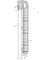
本明細書に開示された技術の実施形態1について、図1から図19を参照しつつ説明する。本実施形態に係るスライド配線装置10は、ワイヤーハーネス配索装置11と、レール12と、スライダ13と、を備える。本実施形態のスライド配線装置10は、自動車等の車両(図示せず)の車体(図示せず)とシート14との間にワイヤーハーネス15を配索するものである。以下では、図1のX方向を右方、Y方向を前方、Z方向を上方として説明する。複数の同一部材については、一の部材にのみ符号を付し、他の部材については符号を省略する場合がある。
<First embodiment>
Embodiment 1 of the technology disclosed in the present specification will be described with reference to FIGS. 1 to 19 . The
(係合手段22)
図19に示すように、プロテクタ21と、ケース16とは、係合手段22により、着脱可能に係合されている。本実施形態に係る係合手段22は、ケース16の開口部30の孔縁部から後方に延びて形成された係合部43と、プロテクタ21の後端部であって、係合部43と対応する位置から前方に延びて形成された被係合部44である。
(Engaging means 22)
As shown in FIG. 19, the
図10に示すように、係合部43は、ケース16の開口部30の孔縁部のうち、右側縁に形成されている。なお、係合部43が開口部30の孔縁部に設けられているとは、係合部43が開口部30の孔縁部から連続して延びるように形成された場合を含むと共に、係合部43が開口部30の孔縁部に形成されていると実質的に認められる程度に近接して設けられている場合を含む。図11に示すように、係合部43は前後方向に延びる基壁45を有する。基壁45の壁面は、上下方向に沿って延びている。図10、図11、及び図12に示すように、基壁45の左側面には、上端縁、前端縁、及び下端縁から左方に突出すると共に、被係合部44の側縁を収容可能な溝部46が形成されている。基壁45と、溝部46との間に囲まれた空間内に、プロテクタ21の被係合部44の上端縁、前端縁、及び下端縁が挿入されるようになっている。基壁45のうち、左側面には、左方に突出する係合突起47が設けられている。基壁45のうち、右側面には、前後方向に延びると共に右方に突出する補強リブ48が設けられている。
As shown in FIG. 10, the
図5及び図7に示すように、被係合部44は、プロテクタ21の後端部のうち、右側の側壁から前後方向に延びて形成されている。被係合部44は、左右方向に弾性変形可能な板状をなしている。被係合部44の右側面には、上下方向に延びる係合溝49が形成されている。この係合溝49に係合部43の係合突起47が後方から係合することにより、プロテクタ21がケース16に対して後方に移動することが規制されるようになっている。被係合部44の前端部は、上下方向について先細り形状をなしている。これにより、ケース16の係合部43に形成された溝部46に進入しやすくなっている。
As shown in FIGS. 5 and 7, the engaged portion 44 is formed to extend in the front-rear direction from the right side wall of the rear end of the
電線17を外装体18の筒状のユニット19の内部に挿通させる。外装体18の一方の端部と、この端部から導出された電線17とを、第1部材31及び第2部材32で挟持することにより、外装体18の一方の端部にプロテクタ21を装着する。これにより、ワイヤーハーネス15が完成する。
The
ケース16に設けられた係合部43に、後方から前方へと、プロテクタ21の被係合部44を接近させる。被係合部44の前端部のうち、上下両側縁が、係合部43の後端部の上下両側縁に形成された溝部46の内部に進入する。
The engaged portion 44 of the
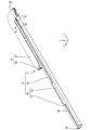
本実施形態に係るスライド配線装置10は、ワイヤーハーネス配索装置11と、ケース16の開口部30に一方の端部が配されると共に、開口部30からワイヤーハーネス15が導出される方向に沿って延びるレール12と、レール12に対してスライド可能に配されると共に、プロテクタ21と固定されたスライダ13と、を備えている。このように、ワイヤーハーネス配索装置11を、スライド配線装置10に適用することができる。
In the
(2)本実施形態では、ケース16に設けられた係合部43が、電線17がケース16から導出される方向に沿って延出される構成としたが、これに限られず、プロテクタ21に設けられた被係合部44が、電線17がケース16から導出される方向に沿って延出されている形態としてもよい。
In (2) In the present embodiment, the
(3)本実施形態においては、係合手段22によるケース16とプロテクタ21との係合が解除される方向は、開口部30から電線17が導出される方向に平行であったが、これに限られず、例えば、係合手段22がクリップの場合のように、開口部30から電線17が導出される方向と交差する方向に沿ってクリップをケース16及びプロテクタ21から離脱させる構成としてもよい。
(3) In the present embodiment, the direction in which the engagement between the
Priority Applications (5)
| Application Number | Priority Date | Filing Date | Title |
|---|---|---|---|
| JP2017152205A JP6760228B2 (en) | 2017-08-07 | 2017-08-07 | Wire harness wiring device and slide wiring device |
| US16/636,663 US11203308B2 (en) | 2017-08-07 | 2018-07-26 | Wire harness routing device and slide wiring device |
| PCT/JP2018/028024 WO2019031254A1 (en) | 2017-08-07 | 2018-07-26 | Wire harness routing device and slide wiring device |
| DE112018004013.5T DE112018004013T5 (en) | 2017-08-07 | 2018-07-26 | Cable harness guiding device and sliding wiring device |
| CN201880048217.6A CN110959238B (en) | 2017-08-07 | 2018-07-26 | Wire harness routing device and sliding routing device |
Applications Claiming Priority (1)
| Application Number | Priority Date | Filing Date | Title |
|---|---|---|---|
| JP2017152205A JP6760228B2 (en) | 2017-08-07 | 2017-08-07 | Wire harness wiring device and slide wiring device |
Publications (3)
| Publication Number | Publication Date |
|---|---|
| JP2019033570A JP2019033570A (en) | 2019-02-28 |
| JP2019033570A5 true JP2019033570A5 (en) | 2019-12-26 |
| JP6760228B2 JP6760228B2 (en) | 2020-09-23 |
Family
ID=65271164
Family Applications (1)
| Application Number | Title | Priority Date | Filing Date |
|---|---|---|---|
| JP2017152205A Active JP6760228B2 (en) | 2017-08-07 | 2017-08-07 | Wire harness wiring device and slide wiring device |
Country Status (5)
| Country | Link |
|---|---|
| US (1) | US11203308B2 (en) |
| JP (1) | JP6760228B2 (en) |
| CN (1) | CN110959238B (en) |
| DE (1) | DE112018004013T5 (en) |
| WO (1) | WO2019031254A1 (en) |
Families Citing this family (3)
| Publication number | Priority date | Publication date | Assignee | Title |
|---|---|---|---|---|
| JP2021069153A (en) * | 2019-10-18 | 2021-04-30 | 矢崎総業株式会社 | Slide power supply device |
| FR3114057B1 (en) * | 2020-09-15 | 2022-12-02 | Faurecia Sieges Dautomobile | Electrical cable guide device for motor vehicle seat rail |
| KR20220060244A (en) * | 2020-11-04 | 2022-05-11 | 현대자동차주식회사 | Seat rail for vehicle |
Family Cites Families (14)
| Publication number | Priority date | Publication date | Assignee | Title |
|---|---|---|---|---|
| US7000967B2 (en) * | 2002-12-27 | 2006-02-21 | Ts Tech Co., Ltd. | Slidable vehicle seat provided with automotive electronic parts |
| JP4095940B2 (en) * | 2003-08-13 | 2008-06-04 | 矢崎総業株式会社 | Power supply device for slide sheet |
| US7730669B2 (en) * | 2003-09-22 | 2010-06-08 | Sumitomo Wiring Systems, Ltd. | Device for guiding a conductor path for slide door |
| JP4263684B2 (en) * | 2004-08-06 | 2009-05-13 | 矢崎総業株式会社 | Power supply device for slide |
| JP4403091B2 (en) * | 2005-03-03 | 2010-01-20 | 矢崎総業株式会社 | Power supply device |
| JP2009194990A (en) * | 2008-02-13 | 2009-08-27 | Yazaki Corp | Electric supply device for slide structure |
| EP2360062B1 (en) * | 2008-12-16 | 2016-09-28 | Yazaki Corporation | Harness cabling device |
| JP5356937B2 (en) * | 2009-07-22 | 2013-12-04 | 矢崎総業株式会社 | Wire harness wiring device |
| JP5248436B2 (en) * | 2009-07-22 | 2013-07-31 | 矢崎総業株式会社 | Wire harness wiring device |
| JP2012045994A (en) | 2010-08-25 | 2012-03-08 | Sumitomo Wiring Syst Ltd | Slide wiring device |
| JP5800608B2 (en) | 2011-02-23 | 2015-10-28 | 矢崎総業株式会社 | Harness wiring device |
| JP6390906B2 (en) * | 2014-12-03 | 2018-09-19 | 株式会社オートネットワーク技術研究所 | Wire harness mounting structure and wiring unit |
| JP6168110B2 (en) | 2015-07-07 | 2017-07-26 | 住友電装株式会社 | Wire harness wiring device for slide sheet |
| JP6436039B2 (en) * | 2015-10-01 | 2018-12-12 | 株式会社オートネットワーク技術研究所 | Slide wiring device |
-
2017
- 2017-08-07 JP JP2017152205A patent/JP6760228B2/en active Active
-
2018
- 2018-07-26 CN CN201880048217.6A patent/CN110959238B/en active Active
- 2018-07-26 US US16/636,663 patent/US11203308B2/en active Active
- 2018-07-26 WO PCT/JP2018/028024 patent/WO2019031254A1/en active Application Filing
- 2018-07-26 DE DE112018004013.5T patent/DE112018004013T5/en active Pending
Similar Documents
| Publication | Publication Date | Title |
|---|---|---|
| US9573536B2 (en) | Wire harness routing device for sliding seat | |
| JP2019033570A5 (en) | ||
| JP6436039B2 (en) | Slide wiring device | |
| US9963093B2 (en) | Wire harness attachment structure and wiring unit | |
| JP6589819B2 (en) | Wire harness module | |
| JP6760228B2 (en) | Wire harness wiring device and slide wiring device | |
| JP2018074774A5 (en) | ||
| JP2012113835A (en) | Attachment structure and attachment member for connector | |
| US10464505B2 (en) | Cable retention member | |
| JP2017093016A (en) | Wire harness routing device | |
| JP6014820B2 (en) | Vehicle under cover assembly structure | |
| JP5733243B2 (en) | Camera cover | |
| JP6358130B2 (en) | Vehicle waterproof structure | |
| JP6182089B2 (en) | Instrument panel structure | |
| JP6303144B2 (en) | Blank panel | |
| JP5939200B2 (en) | Connecting structure of slide sheet and slider | |
| JP6680189B2 (en) | Wire cover and connector | |
| JP5264253B2 (en) | Wire harness wiring structure in vehicle seat | |
| JP2016122563A (en) | connector | |
| JP2007215322A (en) | Cabling structure of wire harness | |
| JP2016000568A (en) | Vehicular finisher installing structure | |
| JP2014065370A (en) | Bumper mounting retainer | |
| JP5870397B2 (en) | Wire harness protector mounting structure | |
| JP6295838B2 (en) | Radiator grill and vehicle | |
| JP5584009B2 (en) | Vehicle assembly parts |