JP6756228B2 - In-vehicle display control device - Google Patents
In-vehicle display control device Download PDFInfo
- Publication number
- JP6756228B2 JP6756228B2 JP2016199185A JP2016199185A JP6756228B2 JP 6756228 B2 JP6756228 B2 JP 6756228B2 JP 2016199185 A JP2016199185 A JP 2016199185A JP 2016199185 A JP2016199185 A JP 2016199185A JP 6756228 B2 JP6756228 B2 JP 6756228B2
- Authority
- JP
- Japan
- Prior art keywords
- display
- vehicle
- display control
- control device
- driver
- Prior art date
- Legal status (The legal status is an assumption and is not a legal conclusion. Google has not performed a legal analysis and makes no representation as to the accuracy of the status listed.)
- Expired - Fee Related
Links
- 238000000034 method Methods 0.000 claims description 43
- 230000008569 process Effects 0.000 claims description 26
- 206010047571 Visual impairment Diseases 0.000 claims description 2
- 239000013589 supplement Substances 0.000 claims 1
- 238000001514 detection method Methods 0.000 description 26
- 238000012545 processing Methods 0.000 description 26
- 230000002093 peripheral effect Effects 0.000 description 18
- 230000004304 visual acuity Effects 0.000 description 17
- 238000012806 monitoring device Methods 0.000 description 16
- 230000000007 visual effect Effects 0.000 description 13
- 230000009466 transformation Effects 0.000 description 12
- 230000008859 change Effects 0.000 description 11
- 230000006870 function Effects 0.000 description 9
- 241000282412 Homo Species 0.000 description 5
- 230000000694 effects Effects 0.000 description 5
- 206010020675 Hypermetropia Diseases 0.000 description 4
- 230000006978 adaptation Effects 0.000 description 4
- 238000012937 correction Methods 0.000 description 4
- 230000004305 hyperopia Effects 0.000 description 4
- 201000006318 hyperopia Diseases 0.000 description 4
- 208000001491 myopia Diseases 0.000 description 4
- 230000004379 myopia Effects 0.000 description 4
- 201000009310 astigmatism Diseases 0.000 description 3
- 230000003190 augmentative effect Effects 0.000 description 3
- 239000011159 matrix material Substances 0.000 description 3
- 230000003287 optical effect Effects 0.000 description 3
- 239000004065 semiconductor Substances 0.000 description 3
- 230000001133 acceleration Effects 0.000 description 2
- 230000002411 adverse Effects 0.000 description 2
- 230000007613 environmental effect Effects 0.000 description 2
- 206010025482 malaise Diseases 0.000 description 2
- 230000004044 response Effects 0.000 description 2
- 230000002123 temporal effect Effects 0.000 description 2
- 230000007704 transition Effects 0.000 description 2
- 125000002066 L-histidyl group Chemical group [H]N1C([H])=NC(C([H])([H])[C@](C(=O)[*])([H])N([H])[H])=C1[H] 0.000 description 1
- 230000003542 behavioural effect Effects 0.000 description 1
- 230000008901 benefit Effects 0.000 description 1
- 230000004397 blinking Effects 0.000 description 1
- 210000004556 brain Anatomy 0.000 description 1
- 238000004891 communication Methods 0.000 description 1
- 230000000295 complement effect Effects 0.000 description 1
- 239000000470 constituent Substances 0.000 description 1
- 238000010586 diagram Methods 0.000 description 1
- 238000006073 displacement reaction Methods 0.000 description 1
- 230000004438 eyesight Effects 0.000 description 1
- 230000010365 information processing Effects 0.000 description 1
- 238000009434 installation Methods 0.000 description 1
- 238000012423 maintenance Methods 0.000 description 1
- 238000005259 measurement Methods 0.000 description 1
- 230000007246 mechanism Effects 0.000 description 1
- 230000004048 modification Effects 0.000 description 1
- 238000012986 modification Methods 0.000 description 1
- 208000014733 refractive error Diseases 0.000 description 1
- 239000000725 suspension Substances 0.000 description 1
- 238000000844 transformation Methods 0.000 description 1
- 238000011426 transformation method Methods 0.000 description 1
- 230000001131 transforming effect Effects 0.000 description 1
Images


Classifications
-
- G—PHYSICS
- G02—OPTICS
- G02B—OPTICAL ELEMENTS, SYSTEMS OR APPARATUS
- G02B27/00—Optical systems or apparatus not provided for by any of the groups G02B1/00 - G02B26/00, G02B30/00
- G02B27/01—Head-up displays
- G02B27/0101—Head-up displays characterised by optical features
-
- G—PHYSICS
- G06—COMPUTING; CALCULATING OR COUNTING
- G06F—ELECTRIC DIGITAL DATA PROCESSING
- G06F3/00—Input arrangements for transferring data to be processed into a form capable of being handled by the computer; Output arrangements for transferring data from processing unit to output unit, e.g. interface arrangements
- G06F3/01—Input arrangements or combined input and output arrangements for interaction between user and computer
- G06F3/011—Arrangements for interaction with the human body, e.g. for user immersion in virtual reality
- G06F3/013—Eye tracking input arrangements
-
- B—PERFORMING OPERATIONS; TRANSPORTING
- B60—VEHICLES IN GENERAL
- B60K—ARRANGEMENT OR MOUNTING OF PROPULSION UNITS OR OF TRANSMISSIONS IN VEHICLES; ARRANGEMENT OR MOUNTING OF PLURAL DIVERSE PRIME-MOVERS IN VEHICLES; AUXILIARY DRIVES FOR VEHICLES; INSTRUMENTATION OR DASHBOARDS FOR VEHICLES; ARRANGEMENTS IN CONNECTION WITH COOLING, AIR INTAKE, GAS EXHAUST OR FUEL SUPPLY OF PROPULSION UNITS IN VEHICLES
- B60K35/00—Instruments specially adapted for vehicles; Arrangement of instruments in or on vehicles
- B60K35/20—Output arrangements, i.e. from vehicle to user, associated with vehicle functions or specially adapted therefor
- B60K35/21—Output arrangements, i.e. from vehicle to user, associated with vehicle functions or specially adapted therefor using visual output, e.g. blinking lights or matrix displays
- B60K35/23—Head-up displays [HUD]
- B60K35/233—Head-up displays [HUD] controlling the size or position in display areas of virtual images depending on the condition of the vehicle or the driver
-
- B—PERFORMING OPERATIONS; TRANSPORTING
- B60—VEHICLES IN GENERAL
- B60K—ARRANGEMENT OR MOUNTING OF PROPULSION UNITS OR OF TRANSMISSIONS IN VEHICLES; ARRANGEMENT OR MOUNTING OF PLURAL DIVERSE PRIME-MOVERS IN VEHICLES; AUXILIARY DRIVES FOR VEHICLES; INSTRUMENTATION OR DASHBOARDS FOR VEHICLES; ARRANGEMENTS IN CONNECTION WITH COOLING, AIR INTAKE, GAS EXHAUST OR FUEL SUPPLY OF PROPULSION UNITS IN VEHICLES
- B60K35/00—Instruments specially adapted for vehicles; Arrangement of instruments in or on vehicles
- B60K35/20—Output arrangements, i.e. from vehicle to user, associated with vehicle functions or specially adapted therefor
- B60K35/21—Output arrangements, i.e. from vehicle to user, associated with vehicle functions or specially adapted therefor using visual output, e.g. blinking lights or matrix displays
- B60K35/23—Head-up displays [HUD]
- B60K35/235—Head-up displays [HUD] with means for detecting the driver's gaze direction or eye points
-
- B—PERFORMING OPERATIONS; TRANSPORTING
- B60—VEHICLES IN GENERAL
- B60K—ARRANGEMENT OR MOUNTING OF PROPULSION UNITS OR OF TRANSMISSIONS IN VEHICLES; ARRANGEMENT OR MOUNTING OF PLURAL DIVERSE PRIME-MOVERS IN VEHICLES; AUXILIARY DRIVES FOR VEHICLES; INSTRUMENTATION OR DASHBOARDS FOR VEHICLES; ARRANGEMENTS IN CONNECTION WITH COOLING, AIR INTAKE, GAS EXHAUST OR FUEL SUPPLY OF PROPULSION UNITS IN VEHICLES
- B60K35/00—Instruments specially adapted for vehicles; Arrangement of instruments in or on vehicles
- B60K35/20—Output arrangements, i.e. from vehicle to user, associated with vehicle functions or specially adapted therefor
- B60K35/28—Output arrangements, i.e. from vehicle to user, associated with vehicle functions or specially adapted therefor characterised by the type of the output information, e.g. video entertainment or vehicle dynamics information; characterised by the purpose of the output information, e.g. for attracting the attention of the driver
-
- B—PERFORMING OPERATIONS; TRANSPORTING
- B60—VEHICLES IN GENERAL
- B60K—ARRANGEMENT OR MOUNTING OF PROPULSION UNITS OR OF TRANSMISSIONS IN VEHICLES; ARRANGEMENT OR MOUNTING OF PLURAL DIVERSE PRIME-MOVERS IN VEHICLES; AUXILIARY DRIVES FOR VEHICLES; INSTRUMENTATION OR DASHBOARDS FOR VEHICLES; ARRANGEMENTS IN CONNECTION WITH COOLING, AIR INTAKE, GAS EXHAUST OR FUEL SUPPLY OF PROPULSION UNITS IN VEHICLES
- B60K35/00—Instruments specially adapted for vehicles; Arrangement of instruments in or on vehicles
- B60K35/65—Instruments specially adapted for specific vehicle types or users, e.g. for left- or right-hand drive
-
- B—PERFORMING OPERATIONS; TRANSPORTING
- B60—VEHICLES IN GENERAL
- B60R—VEHICLES, VEHICLE FITTINGS, OR VEHICLE PARTS, NOT OTHERWISE PROVIDED FOR
- B60R11/00—Arrangements for holding or mounting articles, not otherwise provided for
- B60R11/02—Arrangements for holding or mounting articles, not otherwise provided for for radio sets, television sets, telephones, or the like; Arrangement of controls thereof
-
- B—PERFORMING OPERATIONS; TRANSPORTING
- B60—VEHICLES IN GENERAL
- B60R—VEHICLES, VEHICLE FITTINGS, OR VEHICLE PARTS, NOT OTHERWISE PROVIDED FOR
- B60R11/00—Arrangements for holding or mounting articles, not otherwise provided for
- B60R11/04—Mounting of cameras operative during drive; Arrangement of controls thereof relative to the vehicle
-
- G—PHYSICS
- G02—OPTICS
- G02B—OPTICAL ELEMENTS, SYSTEMS OR APPARATUS
- G02B27/00—Optical systems or apparatus not provided for by any of the groups G02B1/00 - G02B26/00, G02B30/00
- G02B27/01—Head-up displays
-
- B—PERFORMING OPERATIONS; TRANSPORTING
- B60—VEHICLES IN GENERAL
- B60K—ARRANGEMENT OR MOUNTING OF PROPULSION UNITS OR OF TRANSMISSIONS IN VEHICLES; ARRANGEMENT OR MOUNTING OF PLURAL DIVERSE PRIME-MOVERS IN VEHICLES; AUXILIARY DRIVES FOR VEHICLES; INSTRUMENTATION OR DASHBOARDS FOR VEHICLES; ARRANGEMENTS IN CONNECTION WITH COOLING, AIR INTAKE, GAS EXHAUST OR FUEL SUPPLY OF PROPULSION UNITS IN VEHICLES
- B60K2360/00—Indexing scheme associated with groups B60K35/00 or B60K37/00 relating to details of instruments or dashboards
- B60K2360/16—Type of output information
- B60K2360/167—Vehicle dynamics information
-
- B—PERFORMING OPERATIONS; TRANSPORTING
- B60—VEHICLES IN GENERAL
- B60K—ARRANGEMENT OR MOUNTING OF PROPULSION UNITS OR OF TRANSMISSIONS IN VEHICLES; ARRANGEMENT OR MOUNTING OF PLURAL DIVERSE PRIME-MOVERS IN VEHICLES; AUXILIARY DRIVES FOR VEHICLES; INSTRUMENTATION OR DASHBOARDS FOR VEHICLES; ARRANGEMENTS IN CONNECTION WITH COOLING, AIR INTAKE, GAS EXHAUST OR FUEL SUPPLY OF PROPULSION UNITS IN VEHICLES
- B60K2360/00—Indexing scheme associated with groups B60K35/00 or B60K37/00 relating to details of instruments or dashboards
- B60K2360/20—Optical features of instruments
- B60K2360/33—Illumination features
- B60K2360/334—Projection means
-
- B—PERFORMING OPERATIONS; TRANSPORTING
- B60—VEHICLES IN GENERAL
- B60W—CONJOINT CONTROL OF VEHICLE SUB-UNITS OF DIFFERENT TYPE OR DIFFERENT FUNCTION; CONTROL SYSTEMS SPECIALLY ADAPTED FOR HYBRID VEHICLES; ROAD VEHICLE DRIVE CONTROL SYSTEMS FOR PURPOSES NOT RELATED TO THE CONTROL OF A PARTICULAR SUB-UNIT
- B60W2540/00—Input parameters relating to occupants
- B60W2540/221—Physiology, e.g. weight, heartbeat, health or special needs
-
- G—PHYSICS
- G02—OPTICS
- G02B—OPTICAL ELEMENTS, SYSTEMS OR APPARATUS
- G02B27/00—Optical systems or apparatus not provided for by any of the groups G02B1/00 - G02B26/00, G02B30/00
- G02B27/01—Head-up displays
- G02B27/0179—Display position adjusting means not related to the information to be displayed
- G02B2027/0187—Display position adjusting means not related to the information to be displayed slaved to motion of at least a part of the body of the user, e.g. head, eye
-
- G—PHYSICS
- G02—OPTICS
- G02B—OPTICAL ELEMENTS, SYSTEMS OR APPARATUS
- G02B27/00—Optical systems or apparatus not provided for by any of the groups G02B1/00 - G02B26/00, G02B30/00
- G02B27/0093—Optical systems or apparatus not provided for by any of the groups G02B1/00 - G02B26/00, G02B30/00 with means for monitoring data relating to the user, e.g. head-tracking, eye-tracking
Landscapes
- Engineering & Computer Science (AREA)
- Physics & Mathematics (AREA)
- Mechanical Engineering (AREA)
- General Physics & Mathematics (AREA)
- Transportation (AREA)
- Chemical & Material Sciences (AREA)
- Combustion & Propulsion (AREA)
- General Engineering & Computer Science (AREA)
- Theoretical Computer Science (AREA)
- Optics & Photonics (AREA)
- Human Computer Interaction (AREA)
- Instrument Panels (AREA)
- Controls And Circuits For Display Device (AREA)
- Fittings On The Vehicle Exterior For Carrying Loads, And Devices For Holding Or Mounting Articles (AREA)
Description
本開示は、車両に搭載されるヘッドアップディスプレイによる表示を制御する車載表示制御装置に関する。 The present disclosure relates to an in-vehicle display control device that controls display by a head-up display mounted on a vehicle.
従来、自動車の運転者の前方視界に虚像による表示像を形成することにより、運転者の視線の先に情報を表示する、いわゆるヘッドアップディスプレイ(以下、HUD)が知られている。この種のHUDの実用例として、車両のウインドシールド越しに見える実風景に情報を重ねて表示することで、運転者が認識する実風景を拡張する、いわゆる拡張現実(すなわち、AR)がある。例えば、交差点において自車両が進むべき進路方向を示す矢印等の図柄を、実風景の道路の形状に合わせて表示させたり、運転者が見ていない道路標識に対して強調表示を施すことで、注意を喚起するといったものがある。 Conventionally, a so-called head-up display (hereinafter, HUD) is known in which information is displayed ahead of the driver's line of sight by forming a virtual image display image in the front view of the driver of the automobile. As a practical example of this type of HUD, there is so-called augmented reality (that is, AR) in which the actual landscape recognized by the driver is expanded by superimposing information on the actual landscape seen through the windshield of the vehicle. For example, by displaying a pattern such as an arrow indicating the direction in which the vehicle should travel at an intersection according to the shape of the road in the actual landscape, or by highlighting a road sign that the driver does not see. There is something that calls attention.
しかしながら、車両内において運転者の顔の位置は必ずしも固定された位置にあるわけではない。運転者の顔の位置が変化することで、運転者の視界において実風景とHUDの表示像との位置にずれが生じてしまい、重畳表示の利点を活かせない場合がある。さらには、HUDの表示像が適切な位置に表示されないことで、運転者に違和感や誤解を与えるといった問題が生じることがある。 However, the position of the driver's face in the vehicle is not always fixed. When the position of the driver's face changes, the position of the actual landscape and the display image of the HUD may shift in the driver's field of view, and the advantage of the superimposed display may not be utilized. Further, the display image of the HUD is not displayed at an appropriate position, which may cause a problem that the driver feels uncomfortable or misunderstood.
上述のような問題に対して、特許文献1には、運転者の眼の位置を検出し、運転者の眼の位置と道路上の誘導経路とを結ぶ直線状に表示像を結像させることにより、HUDの表示像を適切な位置に表示する技術が開示されている。
In response to the above-mentioned problems,
しかしながら、HUDの表示像が実風景とずれて表示される要因は、運転者の顔の位置に関するものだけに限らない。例えば、車両の挙動の急激な変化や外部環境の性状、運転者の身体能力等に関する様々な要因によって、HUDの表示像と実風景とのずれが生じる可能性がある。また、これらの要因によりHUDの表示像と実風景との不適合が生じ、運転者が違和感を覚える場合もある。 However, the factor that the display image of the HUD is displayed out of alignment with the actual scenery is not limited to the position of the driver's face. For example, there is a possibility that the display image of the HUD may deviate from the actual landscape due to various factors such as a sudden change in the behavior of the vehicle, the properties of the external environment, and the physical ability of the driver. In addition, these factors may cause the display image of the HUD to be incompatible with the actual landscape, which may cause the driver to feel uncomfortable.
本開示は、上述の問題を解決するためになされたものである。本開示は、HUDの表示像と実風景とのずれや違和感を生じる様々な要因に対して、HUDの表示像を適切に表示するための技術を提供する。 The present disclosure has been made to solve the above-mentioned problems. The present disclosure provides a technique for appropriately displaying the display image of the HUD with respect to various factors that cause a deviation or discomfort between the display image of the HUD and the actual landscape.
本開示の一態様に係る車載表示制御装置(10)は、車両の運転者に対して表示すべき情報を運転者の視界前方において認識される虚像からなる表示像として表示するヘッドアップディスプレイ(28)を制御するものである。この車載表示制御装置は、空間情報取得部(S110)と、視点情報取得部(S120)と、表示制御部(S130〜S160)と、出力部(S170)とを備える。なお、この欄及び特許請求の範囲に記載した括弧内の符号は、一つの態様として後述する実施形態に記載の具体的手段との対応関係を示すものであって、本開示の技術的範囲を限定するものではない。 The vehicle-mounted display control device (10) according to one aspect of the present disclosure is a head-up display (28) that displays information to be displayed to the driver of the vehicle as a display image composed of a virtual image recognized in front of the driver's field of view. ) Is controlled. This in-vehicle display control device includes a spatial information acquisition unit (S110), a viewpoint information acquisition unit (S120), a display control unit (S130 to S160), and an output unit (S170). In addition, the reference numerals in parentheses described in this column and the scope of claims indicate the correspondence with the specific means described in the embodiment described later as one embodiment, and the technical scope of the present disclosure is defined. It is not limited.
空間情報取得部は、車両の前方の実風景に存在する物体の絶対座標系における位置を表す情報を取得するように構成されている。視点情報取得部は、運転者の眼の位置を表す情報を取得するように構成されている。表示制御部は、物体の位置の情報と眼の位置の情報とに基づいて、運転者の視界において特定の対象物に表示像が重畳して表示されるように、表示像を投影する位置を少なくとも含む表示像の表示態様を決定するように構成されている。出力部は、表示制御部によって決定された表示態様に従って、ヘッドアップディスプレイに表示像を形成させるように構成されている。 The spatial information acquisition unit is configured to acquire information representing the position of an object existing in the actual landscape in front of the vehicle in the absolute coordinate system. The viewpoint information acquisition unit is configured to acquire information indicating the position of the driver's eyes. Based on the information on the position of the object and the information on the position of the eyes, the display control unit determines the position to project the display image so that the display image is superimposed and displayed on a specific object in the driver's field of view. It is configured to determine the display mode of at least the display image to be included. The output unit is configured to form a display image on the head-up display according to the display mode determined by the display control unit.
また、表示制御部は、挙動関連制御、環境関連制御、及び身体能力関連制御の少なくとも何れかの制御を実行するように構成されている。挙動関連制御は、車両の挙動を表す情報に基づいて表示像の表示態様を調節する制御である。環境関連制御は、外部環境の性状を現す情報に基づいて表示像の表示態様を調節する制御である。身体能力関連制御は、運転者の身体能力を表す情報に基づいて表示像の表示態様を調節する制御である。 Further, the display control unit is configured to execute at least one of behavior-related control, environment-related control, and physical ability-related control. The behavior-related control is a control that adjusts the display mode of the display image based on the information representing the behavior of the vehicle. The environment-related control is a control that adjusts the display mode of the display image based on the information showing the properties of the external environment. The physical ability-related control is a control that adjusts the display mode of the display image based on the information representing the physical ability of the driver.
本開示に係る車載表示制御装置によれば、HUDの表示像と実風景とのずれや違和感を生じ得る様々な要因に応じて、表示像の表示態様を調節することができる。これにより、HUDにおける表示像の不適合や違和感を低減できる。 According to the in-vehicle display control device according to the present disclosure, the display mode of the display image can be adjusted according to various factors that may cause a deviation or discomfort between the display image of the HUD and the actual landscape. As a result, incompatibility and discomfort of the display image in the HUD can be reduced.
以下、本開示の実施形態を図面に基づいて説明する。なお、本開示は下記の実施形態に限定されるものではなく様々な態様にて実施することが可能である。
[車載表示システムの構成の説明]
実施形態の車載表示システムの構成について、図1を参照しながら説明する。この車載表示システムは、HUDを用いて運転者に情報を提示するシステムであり、車両1に搭載されている。図1に例示されるとおり、車載表示システムは、車載表示制御装置10と、この車載表示制御装置10に接続される各部を含んで構成されている。車載表示制御装置10には、周辺監視装置12、視点検出部18、視力検出部20、車両挙動検出部22、位置検出部24、地図情報取得部26、及びヘッドアップディスプレイプロジェクタ(以下、HUDプロジェクタ)28が接続される。
Hereinafter, embodiments of the present disclosure will be described with reference to the drawings. The present disclosure is not limited to the following embodiments, and can be implemented in various embodiments.
[Explanation of in-vehicle display system configuration]
The configuration of the vehicle-mounted display system of the embodiment will be described with reference to FIG. This in-vehicle display system is a system that presents information to the driver using the HUD, and is mounted on the
車載表示制御装置10は、図示しないCPU、RAM、ROM、フラッシュメモリ等の半導体メモリ、入出力インタフェース等を中心に構成された情報処理装置である。具体的には、車載表示制御装置10は、HUDプロジェクタ28によって自動車の運転者の前方視界に虚像による表示像を形成することにより、車両1の運転席前方に設けられたウインドシールド越しに運転者が見る実風景に情報を重ねて表示する機能を有する。
The in-vehicle
車載表示制御装置10は、例えば、コンピュータシステムとしての機能が集約されたマイクロコントローラ等により具現化される。車載表示制御装置10の機能は、CPUがROMや半導体メモリ等の非遷移的実体的記憶媒体に格納されたプログラムを実行することにより実現される。なお、車載表示制御装置10を構成するマイクロコントローラの数は1つでも複数でもよい。また、車載表示制御装置10の機能を実現する手法はソフトウェアに限るものではなく、その一部又は全部の要素を論理回路やアナログ回路等を組合せたハードウェアを用いて実現してもよい。
The in-vehicle
周辺監視装置12は、車両1の前方風景を認識するための光学的あるいは電磁的なセンサである。この周辺監視装置12は、例えば、カメラ14及びレーダ16により構成される。カメラ14は、車両1のウインドシールド越しに見える前方領域を撮影し、撮影された画像のデータを車載表示制御装置10に出力する。レーダ16は、カメラ14の撮影範囲と共通の前方領域に向けて電波やレーザ光を発信し、その反射波を受信することにより対象物の有無や対象物までの距離を検出するセンサである。また、カメラ14やレーダ16の他に、赤外線センサや超音波センサ等の対物センサを周辺監視装置12として用いてもよい。
The
視点検出部18は、運転者の眼の位置を測定する機能を有するセンサである。視点検出部18としては、例えば、赤外線カメラにより運転者の眼を撮像し、撮像された眼の画像から画像処理により、車両座標系における運転者の眼の位置の座標を測定する機能を有するカメラシステム等を適用することができる。
The
視力検出部20は、運転者の視力の状態を計測する装置である。視力検出部20の具体例としては、赤外線カメラとコンピュータにより運転者の顔画像を認識する周知のドライバステータスモニタ(以下、DSM)と連携し、オートレフラクトメータの機能を実装することが考えられる。オートレフラクトメータとは、被験者の眼に赤外線光を当て、眼の屈折状態や、近視・遠視・乱視等の有無や度合いを自動的にコンピュータで解析して計測する周知の計測機器である。
The visual
車両挙動検出部22は、車両1の挙動を表す物理量を検出するためのセンサである。この車両挙動検出部22は、ジャイロスコープ、サスペンションストロークセンサ、車高センサ、車輪速センサ、加速度センサ等によって構成される。位置検出部24は、GPS受信機や、ジャイロスコープ、車速センサ等による検出結果に基づき、車両1の現在地を検出するためのものである。
The vehicle behavior detection unit 22 is a sensor for detecting a physical quantity representing the behavior of the
地図情報取得部26は、地形や道路形状等を絶対座標系の座標で表した情報が含まれた地形データを取得し、その取得された地形データを車載表示制御装置10に出力する。地図情報取得部26により取得される地形データは、車両1に搭載された地図情報記憶媒体に収録されているものであってもよいし、外部装置との通信により取得されるものであってもよい。
The map
HUDプロジェクタ28は、運転者に対して表示すべき情報を構成する光をウインドシールドに投射し、運転者の前方視界に虚像による表示像を形成する表示装置である。このHUDプロジェクタ28は、例えば、投影される画像情報を表示する表示パネルが、投影面としてのウインドシールドに直接対面する構造のものや、表示パネルからミラーやレンズ等からなる光学系を介して画像情報を投影する構造のものなどが適宜利用できる。
The
本実施形態において、車載表示制御装置10は、周辺監視装置12により認識された物体の位置と、運転者の眼の位置と基づいて、運転者の視界において特定の対象物にHUDの表示像が重畳して表示されるように、表示像を投影する位置を制御する。その際、次の(1)〜(7)の要因に関して、HUDの表示像を適切に表示するための制御を行うように構成されている。
In the present embodiment, the vehicle-mounted
(1)車両の挙動に関する要因
HUDは車両に取付けられた機構において表示されるものであるため、車両のピッチやロール、ヨー等の急激な変化が発生した場合に、表示像のぶれ等に起因するHUD酔い等の悪影響を運転者に与えるおそれがある。このような悪影響は、HUDの表示像の焦点距離が遠距離である場合に顕著である。このような問題は、ウインドシールド越しに見える実風景に対して運転者の視線が合っている状態から、そこに重畳表示されていたHUDの表示像が突発的にずれることにより、運転者の脳において違和感として認識されることに起因すると推測される。
(1) Factors related to vehicle behavior Since the HUD is displayed by the mechanism attached to the vehicle, it is caused by blurring of the displayed image when a sudden change in the pitch, roll, yaw, etc. of the vehicle occurs. There is a risk of adverse effects such as HUD sickness on the driver. Such an adverse effect is remarkable when the focal length of the display image of the HUD is a long distance. Such a problem is caused by the sudden shift of the HUD display image superimposed on the actual landscape seen through the windshield from the driver's line of sight, resulting in the driver's brain. It is presumed that this is due to the fact that it is recognized as a sense of discomfort.
(2)重畳対象物のばらつきに関する要因
例えば、道路面上に走行レーンの区分等を表す図柄を重畳表示するケースにおいて、道路面に凸凹等のばらつきや歪みあることにより、HUDの表示像の形状と実風景内の重畳対象物の形状とが適合せず、表示のずれが発生する場合がある。このように、重畳対象物の形状の歪みに起因してHUDの表示像と実風景とのずれが生じ、HUD酔い等を誘発するおそれがある。
(2) Factors related to variations in objects to be superimposed For example, in the case where a symbol representing the division of traveling lanes is superimposed and displayed on the road surface, the shape of the HUD display image is formed due to variations or distortions such as irregularities on the road surface. And the shape of the superimposed object in the actual landscape do not match, and the display may shift. As described above, the distortion of the shape of the superimposed object may cause a deviation between the displayed image of the HUD and the actual landscape, which may induce HUD sickness or the like.
(3)車両の挙動への人の適応に関する要因
車両の挙動の変化について、例えば、勾配が一定の坂路やバンクを走行する時のように、定常的な姿勢変化に対して運転者が姿勢を合わせるなどして適応可能な場合、上記(1)の要因における挙動の変化とは区別してHUDの表示態様を調節する必要がある。
(3) Factors related to human adaptation to vehicle behavior Regarding changes in vehicle behavior, for example, when driving on a slope or bank with a constant slope, the driver takes a posture in response to a steady change in posture. If it can be adapted by matching, it is necessary to adjust the display mode of the HUD separately from the change in behavior due to the factor (1) above.
(4)HUDの表示像と環境の性状との相性に関する要因
HUDの表示像は、風景内に半透過的に表示されるものであるため、例えば、天気、環境光の色・明るさ、重畳対象物の色、見通し等の周辺環境の性状によって、見栄えが揺らぐという問題がある。
(4) Factors related to compatibility between the display image of the HUD and the properties of the environment Since the display image of the HUD is semi-transparently displayed in the landscape, for example, the weather, the color / brightness of the ambient light, and the superimposition. There is a problem that the appearance fluctuates depending on the properties of the surrounding environment such as the color of the object and the outlook.
(5)運転者の身体能力に関する要因
運転者の身体能力に個人差があることによって、HUDの表示像の見え方に差が生じる場合がある。例えば、運転者の身体能力の一つとしての視力に関して、運転者が近視傾向であるか遠視傾向であるかによって、HUDの表示像を結像させる適切な焦点距離が異なるという問題がある。
(5) Factors related to the physical ability of the driver Individual differences in the physical ability of the driver may cause differences in the appearance of the displayed image of the HUD. For example, regarding visual acuity as one of the physical abilities of a driver, there is a problem that an appropriate focal length for forming a display image of the HUD differs depending on whether the driver has a tendency toward myopia or hyperopia.
(6)対策の不完全性に対する配慮
上記(1)〜(5)の要因に対する対策を行うシステムには処理限界があるため、対策が不完全であることを前提とした工夫が肝要である。
(6) Consideration for imperfections in countermeasures Since there is a processing limit in the system that takes countermeasures against the factors (1) to (5) above, it is important to devise on the premise that the countermeasures are incomplete.
(7)処理負荷に軽減に関する配慮
上記(1)〜(5)の要因に対する対策を行う処理は、一度の処理でも複数回の座標変換を伴うものであり、また、頻繁に発生する可能性があることから、システムの処理負荷が高くなるという問題がある。このような高い処理能力を実現するシステムは、高コストであるという問題に直結するため、処理負荷を軽減するための工夫が肝要である。
(7) Consideration for reducing the processing load The process of taking measures against the factors (1) to (5) above involves multiple coordinate transformations even in one process, and may occur frequently. Therefore, there is a problem that the processing load of the system becomes high. A system that realizes such a high processing capacity is directly linked to the problem of high cost, so it is essential to devise ways to reduce the processing load.
[表示制御処理の手順の説明]
車載表示制御装置10のCPUがプログラムに従って実行する表示制御処理の手順について、図2のフローチャートを参照しながら説明する。この表示制御処理は、所定の制御周期ごとに繰返し実行される。
[Explanation of display control processing procedure]
The procedure of the display control process executed by the CPU of the in-vehicle
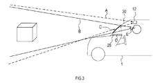
S100では、車載表示制御装置10は、周辺監視装置12の視点位置からの前風景の三次元情報を取得する。具体的には、車載表示制御装置10は、図3に例示されるように、周辺監視装置12の視点位置(すなわち、設置位置)を基準とする視野である視野空間Aについて、絶対座標系における三次元対象物の座標を取得する。
In S100, the vehicle-mounted
三次元対象物の絶対座標系の座標を取得する方法としては次のようにする。第1の方法として、車載表示制御装置10は、周辺監視装置12により取得されたカメラの画像情報やレーダの検出情報に基づいて視野空間Aにおける座標を算出する。第1の方法では、車両挙動検出部22と連携して、ピッチ、ロール、ヨーの変動が発生してない状態で周辺監視装置12により取得された情報と、周辺監視装置12の地上高及び取付角度等を表す既知のパラメータとを用いて、視野空間Aにおける座標を算出する。なお、車両1のピッチが変化している場合であっても、その変動の周波数が規定位置以下である場合、ピッチの変動は発生していないものとして、第1の方法による座標の算出の対象とする。
The method of acquiring the coordinates of the absolute coordinate system of the three-dimensional object is as follows. As the first method, the vehicle-mounted
第2の方法として、車載表示制御装置10は、地図情報取得部26により取得された現在地周辺の地形データに基づいて視野空間Aにおける座標を算出する。この地形データは、地形や道路等の対象物が絶対座標系の座標で記録されていることを前提とする。そして、車載表示制御装置10は、取得された地形データで表される座標と、位置検出部24により検出された車両1の現在地の座標と、周辺監視装置12の地上高及び取付角度等を表す既知のパラメータとを用いて、視野空間Aにおける座標を算出する。
As a second method, the vehicle-mounted
ただし、上記第2の方法では、車両等の移動物に関する三次元情報は取得できない。そのため、車両等の移動物を対象にHUDの表示像を重畳表示することが前提となる場合、基本的には上記第1の方法を適用するものとする。また、上記第1の方法においては、移動物も観測対象となり得ることを考慮し、ピッチ、ロール、ヨー等の変動が発生して観測対象外となる時間の座標は、観測されている過去の複数の時間の座標から予測するものとする。 However, with the above-mentioned second method, three-dimensional information regarding a moving object such as a vehicle cannot be acquired. Therefore, when it is premised that the display image of the HUD is superimposed and displayed on a moving object such as a vehicle, the above-mentioned first method is basically applied. Further, in the above first method, considering that a moving object can also be an observation target, the coordinates of the time when the pitch, roll, yaw, etc. fluctuate and are excluded from the observation target are the coordinates of the past observed. It shall be predicted from the coordinates of multiple times.
図2のフローチャートの説明に戻る。S101では、車載表示制御装置10は、S100において周辺監視装置12により取得された情報について、環境の性状を解析する。具体的には、車載表示制御装置10は、カメラの画像情報に対する画像処理により、環境光の明るさや色、天気(例えば、降雨・降雪)、重畳対象物の色(例えば、車両の色)、重畳対象物の視認性を認識する。なお、S101は、上述の「(3)HUDの表示像と環境の性状との相性に関する要因」への対策に関連する処理である。
Returning to the description of the flowchart of FIG. In S101, the vehicle-mounted
S110では、車載表示制御装置10は、S100において取得された三次元情報に基づいて、特定の重畳対象物に重畳して表示すべき表示像の視野空間Aにおける位置及び形状を表す重畳形状A1を特定する。具体的には、車載表示制御装置10は、周辺監視装置12により取得された前風景の情報から、例えば道路上に標示された区分線や、前方車両、道路標識等の特定の重畳対象物を検出する。そして、検出された重畳対象物に対応する表示像が、周辺監視装置12の視点から見て重畳対象物の位置に重なるように、視野空間Aの座標系における表示像の位置及び形状を重畳形状A1として特定する。
In S110, the vehicle-mounted
S120では、車載表示制御装置10は、視点検出部18により取得された情報に基づいて、運転者の視点位置として眼の位置を取得する。具体的には、車載表示制御装置10は、例えば、視点検出部18を構成する赤外線カメラの取付位置や車両1内の所定位置を基準とする相対座標系における座標として運転者の視点位置を取得する。
In S120, the vehicle-mounted
S121では、車載表示制御装置10は、視力検出部20による検出結果に基づいて、運転者の視力を表す情報を取得する。具体的には、車載表示制御装置10は、運転者の視力を表す情報として、近視・遠視・乱視等の有無や度合いや、眼の屈折状態を取得する。なお、S121は、上述の「(5)運転者の身体能力に関する要因」への対策に関連する処理である。なお、時々刻々変化する視力の変化への対応を省略するのであれば、S121の処理を周期的に行う必要はなく、最初の一度のみ実施するように構成してもよい。また、視力検出部20により視力を実測する代わりに、予め登録されている運転者の視力の情報を読出して取得するように構成してもよい。
In S121, the vehicle-mounted
S130では、車載表示制御装置10は、S110において特定された重畳形状A1について、運転者の視野空間Bに対応する重畳形状A2を取得する。視野空間Bとは、図3に例示されるように、運転者の始点位置Eを基準とする視野である。具体的には、車載表示制御装置10は、S110において特定された重畳形状A1の座標を、S120において取得された運転者の視点位置を基準とする座標系に座標変換することで、視野空間Bにおける表示像の位置及び形状を表す重畳形状A2を算出する。この座標変換は、例えば、周知のビュー変換の手法を用いることが考えられる。ビュー変換とは、図形を見る視点の位置を三次元空間中の別の場所に移して、そこから見た図形を表現するための図法であり、図形を視点の位置と方向から見た座標系(すなわち、視点座標系)に移す座標変換である。具体的には、平行変換行列を用いて図形の位置を視点の座標に合わせて平行移動させる座標変換と、回転変換行列を用いて図形を視点に向けて回転させる座標変換との組み合せからなる。この座標変換により、運転者の視点から見てHUDの表示像が重畳対象物に重畳されて表示されるように重畳形状A2が特定される。
In S130, the vehicle-mounted
S140では、車載表示制御装置10は、重畳対象物に重ねて表示される表示像と併せて表示する表示枠の、投影面空間Cにおける位置及び形状を取得する。この表示枠は、重畳対象物の変位に合わせて表示像を表示可能な所定の範囲を表す枠であり、表示像を囲むようにして描画されるものである。なお、投影面空間Cとは、図3に例示されるように、車両1のウインドシールド30上において、HUDプロジェクタ28から出力される映像光が投影される範囲に割当てられた座標系である。
In S140, the vehicle-mounted
S150では、車載表示制御装置10は、S130において取得された重畳形状A2について、投影面空間Cに対応する重畳形状A3を取得する。具体的には、車載表示制御装置10は、運転者の視点位置と重畳形状A2とを結ぶ投影線に沿って重畳形状A2の座標をウインドシールド上に割当てられた二次元座標系に座標変換することで、投影面空間Cにおける表示像の位置及び形状を表す重畳形状A3を算出する。この座標変換は、例えば、周知の透視投影により、3点座標を持つ重畳形状A2を二次元座標系の仮想面上に投影する手法を用いることが考えられる。透視投影とは、三次元の物体を見たとおりに二次元平面上に描画するための図法であり、物体の見かけの大きさが距離に反比例する。具体的には視点を原点とし、視線がxy平面に垂直なz軸上の負の方向を向いているとした場合、(x,y,z)の位置にある点は、視点から−Aの位置にある前方向の(−Ax/z,−Ay/z)の位置に投影される。なお、このS150において、車載表示制御装置10は、以下に説明するS151,S152,S153の各処理を実行することにより、重畳形状A3について表示態様を補正するように構成されている。
In S150, the vehicle-mounted
S151では、車載表示制御装置10は、重畳対象物の歪みを重畳形状A3の表示態様に反映する。なお、S151は、上述の「(2)重畳対象物のばらつきに関する要因」への対策に関連する処理である。具体的には次のようにする。
In S151, the vehicle-mounted
例えば、道路の走行レーンを区分する区分線に対して、HUDの表示像を重畳表示する事例について説明する。道路整備の観点において、道路上に標示する区分線は、走行レーンに沿って走行する車両の挙動を急変させないために、直線やクロソイド曲線等を用いて急峻な変化が発生しないように描かれているのが一般的である。このような区分線に対して重畳表示されるHUDの表示像も、直線やクロソイド曲線等からなる予め決められた図形を運転者の視点に合わせた形状に変換した表現とするのが一般的である。 For example, an example in which a display image of the HUD is superimposed and displayed on a dividing line that divides a traveling lane of a road will be described. From the viewpoint of road maintenance, the dividing line marked on the road is drawn by using a straight line or clothoid curve so that a steep change does not occur so as not to suddenly change the behavior of the vehicle traveling along the traveling lane. It is common to have. The HUD display image superimposed on such a dividing line is also generally expressed by converting a predetermined figure consisting of a straight line, a clothoid curve, etc. into a shape suitable for the driver's viewpoint. is there.
しかしながら、区分線等が標示されている道路面は、必ずしも綺麗な平面であるとは限らず、凸凹があったり歪んだりすることがある。そのような場合、実風景とHUDの表示像との間で位置や形状のずれが発生するおそれがある。そこで、車載表示制御装置10は、レーダ、カメラ、超音波センサ、赤外線センサ等を用いて地表面の形状を認識する。その地表面に許容値を超える歪みや形状のばらつきがある場合には、地表面に重畳表示する重畳形状A3を、地表面の歪みやばらつきに合わせて変形させる。こうすることにより、地表面に歪みやばらつきがある場合でも、実風景と適合したHUDの表示が継続される。
However, the road surface on which the dividing line or the like is marked is not always a clean flat surface, and may be uneven or distorted. In such a case, there is a possibility that the position or shape may deviate between the actual landscape and the display image of the HUD. Therefore, the vehicle-mounted
ただし、重畳対象物の歪みの程度が甚だしい場合、その重畳対象物の歪みに合わせてHUDの表示像を変形させることで、情報としての意味合いを失う状態にまで歪みが酷くなるという問題がある。そのような問題への対策として、HUDの表示像に対して歪みの上限を設定するということが考えられる。しかしながら、単に歪みの上限を設定するだけでは、実風景と表示像とのズレが発生するという問題が再発することになる。 However, when the degree of distortion of the superimposed object is extremely large, there is a problem that the distortion becomes severe to a state where the meaning as information is lost by deforming the display image of the HUD according to the distortion of the superimposed object. As a countermeasure against such a problem, it is conceivable to set an upper limit of distortion for the display image of the HUD. However, simply setting the upper limit of the distortion will recur the problem that the actual landscape and the displayed image are out of alignment.
そこで、運転者の視点位置から車両進行方向へと向かう線と、地平線とが交差する点を基準点とし、この基準点からの距離に応じて、徐々に歪みの上限を大きくするようにする。このようにすることで、運転者の視野の中心付近においてHUDの情報を的確に伝達しつつ、運転者の視野の周辺においては実風景とHUD表示像とのずれを低減することができる。 Therefore, the point where the line from the driver's viewpoint position toward the vehicle traveling direction and the horizon intersect is set as a reference point, and the upper limit of distortion is gradually increased according to the distance from this reference point. By doing so, it is possible to accurately transmit the HUD information near the center of the driver's field of view and reduce the deviation between the actual landscape and the HUD display image around the driver's field of view.
S152では、車載表示制御装置10は、環境の性状を重畳形状A3の表示態様に反映する。なお、S152は、上述の「(4)HUDの表示像と環境の性状との相性に関する要因」への対策に関連する処理である。具体的には次のようにする。
In S152, the vehicle-mounted
車載表示制御装置10は、S101における環境情報の解析結果に応じて、重畳形状A3の表示態様を補正する。具体的には、重畳対象物の色を判別し、HUDの表示像の色を当該重畳対象物とは異なる色にしてコントラストを強調する。例えば、重畳対象物が白色の車両であれば、HUDの表示像の色を黄色にする。また、黄色の車両に対して警告を表す情報を重畳する場合には、HUDの表示像に黄色を使用せず、黄色の補色等の他の色を使用する。
The in-vehicle
また、車載表示制御装置10は、環境光の色や天気を判別し、HUDの表示像の色を環境に合わせて調節する。例えば、降雪時においては、本来の白色の表示を他の色に変更する。また、夕焼け等により環境光が赤く見える場合、HUDの表示像に赤みを加えることでリアル感を演出する。
Further, the vehicle-mounted
さらには、車載表示制御装置10は、環境情報の解析結果から重畳対象物の視認性が悪いと判断した場合には、HUDの表示像により重畳対象物そのもの形状を模擬した表示を行うように構成されていてもよい。このようにすることで、重畳対象物の視認性を補完することができる。具体的には、降雨や霧等により視界が悪い状況において、走行レーンの区分線がある前提でHUDの重畳表示を行う場合には、走行レーンそのものを模擬した表示を行うことが考えられる。このようにすることで、視界の良否に極力影響されずにHUDによる効果的な拡張現実を実現できる。
Further, the in-vehicle
S153では、車載表示制御装置10は、HUDの表示像の移動表現に関する対策を行う。なお、S153は、上述の「(6)対策の不完全性に対する配慮」に関連する処理である。具体的には次のようにする。
In S153, the vehicle-mounted
システムの処理限界のため対策が不完全であるという前述の問題に対して、その不完全性を補完する処理を行うことで、問題を軽減することが可能となる。例えば、HUDの表示像の位置を、動的かつリアルタイムに人間が認知できる以上の速いリフレッシュレートで補正するということが理想ではあるが、システムによってはそのような高速な処理を実現できないことがある。そのような場合には、車載表示制御装置10は、表示制御処理全体を実現可能な周期で実施するようにし、それに加えて、HUDの表示像を移動させる際に残像表現を加える。このようにすることで、HUDの表示像の移動を滑らかな動きとして運転者に知覚させることができ、ドライバの目への負担を軽減するという効果も期待できる。
It is possible to alleviate the above-mentioned problem that the countermeasure is incomplete due to the processing limit of the system by performing processing that complements the incompleteness. For example, it is ideal to correct the position of the display image of the HUD at a refresh rate faster than humans can perceive in dynamic and real time, but such high-speed processing may not be realized depending on the system. .. In such a case, the vehicle-mounted
また、HUDによる表示が可能な領域が有限である状況において、表示像の位置を移動させるということは、移動によって表示像が表示可能な領域から見切れてしまう可能性がある。そこで、車載表示制御装置10は、HUDの表示可能領域の外周部分に表示像が見切れないための余地となる余裕部分を設定し、その余裕部分を除いた表示可能領域内に収まるようにHUDの表示像の基となる重畳形状A3を生成する。このようにすることで、HUDの表示像の移動が発生しても見切れを発生しづらくすることができる。
Further, in a situation where the area that can be displayed by the HUD is finite, moving the position of the display image may cause the display image to be cut off from the displayable area due to the movement. Therefore, the in-vehicle
また、HUDの表示において重畳対象物への追従が間に合わない程の移動等が突発的に発生することが考えられる。そこで、車載表示制御装置10において遅れを検出する判定手段を設け、遅れが発生することが検出された場合は、その回は表示そのものを更新しないという対策を行うことも有効である。
In addition, it is conceivable that the HUD display suddenly moves to the extent that it cannot follow the superimposed object in time. Therefore, it is also effective to provide a determination means for detecting the delay in the in-vehicle
S160では、車載表示制御装置10は、S150において取得された重畳形状A3について、HUDプロジェクタ28の表示面空間Dに対応する表示形状C4を取得する。表示面空間Dとは、図3に例示されるように、HUDプロジェクタ28の表示パネルにおける画像表示領域に割当てられた二次元座標系である。具体的には、車載表示制御装置10は、投影面空間Cの曲率やHUDプロジェクタ28の光学経路の屈折率等の特性に応じて、重畳形状A3の二次元座標を表示面空間Dの二次元座標系に座標変換することで、表示面空間Dにおける表示像の位置及び形状を表す表示形状C4を算出する。この座標変換は、例えば、投影面空間C及び画像表示領域の2平面間の変換行列を用いて演算される。なお、このS160において、車載表示制御装置10は、以下に説明するS161,S162,S163の各処理を実行することにより、表示形状C4について表示態様を補正するように構成されている。
In S160, the vehicle-mounted
S161では、車載表示制御装置10は、車両1の挙動の変化を表示形状C4の表示態様に反映する。なお、S161は、上述の「(1)車両の挙動に関する要因」への対策に関連する処理である。具体的には次のようにする。
In S161, the vehicle-mounted
車載表示制御装置10は、車両挙動検出部22やカメラ14、レーダ16により取得された情報に基づいて、車両1のピッチ角、ロール角、ヨー角等の車両回転角を計測する。そして、計測された車両回転角と、車輪速センサや加速度センサ等の検出結果とを併用して、車両1の実風景に対する相対的な位置を推定する。そして、車載表示制御装置10は、推定された相対的な位置に基づいて補正前の表示形状C4による表示像と実風景とのずれ量を推定し、このずれ量を修正する。このようにすることで、車両1において一時的な挙動が発生しても、実風景とマッチしたHUDの表示が維持される。
The in-vehicle
S162では、車載表示制御装置10は、S161の処理について運転者の適応要因を反映する。なお、S162は、上述の「(3)車両の挙動への人の適応に関する要因」への対策に関連する処理である。具体的には次のようにする。
In S162, the vehicle-mounted
一定の勾配が連続する登坂や降坂を走行しているときのように、車両のピッチが定常的に傾いている場合には、運転者はその勾配に対して姿勢を合わせることにより適応することができる。これにより、実際には車両がピッチ方向に傾いた状態であっても、運転者の視野はピッチ角0度の状態と変わらないようにすることができる。このため、上述のS161において全てのピッチの変化に対して必ずしもHUDの表示像の表示態様を補正する必要があるわけではない。 When the pitch of the vehicle is constantly tilted, such as when driving uphill or downhill with a constant slope, the driver should adapt by adjusting his / her posture to the slope. Can be done. As a result, even if the vehicle is actually tilted in the pitch direction, the driver's field of view can be kept unchanged from the state where the pitch angle is 0 degrees. Therefore, in S161 described above, it is not always necessary to correct the display mode of the HUD display image for all changes in pitch.
そこで、車載表示制御装置10は、ピッチ角の時間的推移を周波数成分として解析し、所定の下限周波数域に対応するハイパスフィルタ処理を施す。これにより、車載表示制御装置10は、ハイパスフィルタの周波数域より低い緩やかなピッチの変化に対しては、表示形状C4の補正の対象外とする。このようにすることで、緩やかなピッチの変化に対する運転者の適応を、HUDの表示像の表示態様に反映させることができる。
Therefore, the vehicle-mounted
S163では、車載表示制御装置10は、S161の処理について処理負荷を低減するための対策を実施する。なお、S163は、上述の「(7)処理負荷に軽減に関する配慮」に関連する処理である。具体的には次のようにする。
In S163, the vehicle-mounted
HUDによる拡張現実は人間が視覚で認識するものであるため、人間が点滅を認識可能な周波数の限界値(例えば、30〜50Hz程度)を越える周波数域の挙動変化については、表示形状C4の補正を行わないようにする。 Since the augmented reality by the HUD is visually recognized by humans, the display shape C4 is corrected for behavioral changes in the frequency range exceeding the frequency limit value (for example, about 30 to 50 Hz) at which humans can recognize blinking. Do not do.
具体的には、車載表示制御装置10は、ピッチ角、ロール角、ヨー角等の車両姿勢の時間的推移を周波数成分として解析し、所定の上限周波数域に対応するローパスフィルタ処理を施す。これにより、車載表示制御装置10は、人間が認識できない周波数域の挙動変化に対しては、表示形状C4の補正の対象外とする。このように、人間が認識できない不要な挙動変化に対する処理を省略することで、処理負荷を低減することができる。あるいは、運転者がHUDの表示像を周辺視野においてさえも捕捉できない状況においては、車載表示制御装置10が表示態様の補正やHUDの表示そのものを止めるように構成してもよい。これは処理負荷や消費電力の低減という観点で有効である。
Specifically, the vehicle-mounted
S170では、車載表示制御装置10は、S160において取得された表示形状C4をHUDプロジェクタ28の表示パネルに出力する。これにより、HUDプロジェクタ28からウインドシールド30に表示形状C4が投影され、運転者の視界前方において認識される表示像が形成される。なお、このS170において、車載表示制御装置10は、以下に説明するS171の処理を実行することにより、表示形状C4について表示態様を補正するように構成されている。
In S170, the vehicle-mounted
S171では、車載表示制御装置10は、運転者の視力の測定結果を表示形状C4の表示態様に反映する。なお、S171は、上述の「(5)運転者の身体能力に関する要因」への対策に関連する処理である。具体的には次のようにする。
In S171, the vehicle-mounted
車載表示制御装置10は、S121において取得された運転者の視力の情報に基づき、視力の良否や、近視・遠視・乱視等の屈折異常の度合に応じて、運転者からのHUDの表示像との距離の遠近や、HUDの表示像の輝度を調節する。このようにすることで、運転者ごとの視力の個人差や、同一の運転者において疲労等により視力が時々刻々と変化する状況への対応も可能である。
Based on the driver's visual acuity information acquired in S121, the in-vehicle
[効果]
実施形態の車載表示システムによれば、以下の効果を奏する。
車載表示制御装置10によれば、HUDの表示像と実風景とのずれや違和感を生じ得る様々な要因として、車両の挙動や、外部環境の性状、運転者の身体能力等の状況に応じて、HUDの表示像の表示態様を調節することができる。これにより、HUDにおける表示像の不適合や違和感を低減できる。
[effect]
According to the vehicle-mounted display system of the embodiment, the following effects are obtained.
According to the in-vehicle
[特許請求の範囲に記載の構成との対応]
実施形態の各構成と、特許請求の範囲に記載の構成との対応は次のとおりである。
車載表示制御装置10が実行するS100の処理が、空間情報取得部としての処理の一例に相当する。車載表示制御装置10が実行するS120の処理が、視点情報取得部としての処理の一例に相当する。車載表示制御装置10が実行するS110,S130,S150〜S153,S160〜S163,S171の処理が、表示制御部としての処理の一例に相当する。車載表示制御装置10が実行するS170の処理が、出力部としての処理の一例に相当する。
[Correspondence with the configuration described in the claims]
The correspondence between each configuration of the embodiment and the configuration described in the claims is as follows.
The process of S100 executed by the in-vehicle
また、車載表示制御装置10が実行するS161の処理が、挙動関連制御の一例に相当する。車載表示制御装置10が実行するS101,S151,S152の処理が、環境関連制御の一例に相当する。車載表示制御装置10が実行するS121,S171の処理が、身体能力関連制御の一例に相当する。
Further, the process of S161 executed by the vehicle-mounted
[変形例]
上記各実施形態における1つの構成要素が有する機能を複数の構成要素に分担させたり、複数の構成要素が有する機能を1つの構成要素に発揮させたりしてもよい。また、上記各実施形態の構成の一部を省略してもよい。また、上記各実施形態の構成の少なくとも一部を、他の上記実施形態の構成に対して付加、置換等してもよい。なお、特許請求の範囲に記載の文言から特定される技術思想に含まれるあらゆる態様が、本開示の実施形態である。
[Modification example]
The function of one component in each of the above embodiments may be shared by a plurality of components, or the function of the plurality of components may be exerted by one component. Further, a part of the configuration of each of the above embodiments may be omitted. In addition, at least a part of the configuration of each of the above embodiments may be added or replaced with respect to the configuration of the other embodiment. It should be noted that all aspects included in the technical idea specified from the wording described in the claims are embodiments of the present disclosure.
上述した車載表示制御装置10を構成要件とするシステム、車載表示制御装置10としてコンピュータを機能させるためのプログラム、このプログラムを記録した半導体メモリ等の非遷移的実態的記録媒体、表示制御方法等の種々の形態で本開示を実現することもできる。
A system having the above-described in-vehicle
1…車両、10…車載表示制御装置、12…周辺監視装置、14…カメラ、16…レーダ、18…視点検出部、20…視力検出部、22…車両挙動検出部、24…位置検出部、26…地図情報取得部、28…ヘッドアップディスプレイプロジェクタ、30…ウインドシールド。 1 ... vehicle, 10 ... in-vehicle display control device, 12 ... peripheral monitoring device, 14 ... camera, 16 ... radar, 18 ... viewpoint detection unit, 20 ... vision detection unit, 22 ... vehicle behavior detection unit, 24 ... position detection unit, 26 ... Map information acquisition unit, 28 ... Head-up display projector, 30 ... Windshield.
Claims (5)
ための車載表示制御装置(10)であって、
前記車両の前方の実風景に存在する物体の絶対座標系における位置を表す情報を取得するように構成された空間情報取得部(S100)と、
前記運転者の眼の位置を表す情報を取得するように構成された視点情報取得部(S120)と、
前記空間情報取得部により取得された物体の位置と、前記視点情報取得部により取得された眼の位置とに基づいて、前記運転者の視界において特定の対象物に前記表示像が重畳して表示されるように、前記表示像を投影する位置を少なくとも含む前記表示像の表示態様を決定するように構成された表示制御部(S130〜S160)と、
前記表示制御部によって決定された表示態様に従って、前記ヘッドアップディスプレイに前記表示像を形成させるように構成された出力部(S170)とを備え、
前記表示制御部は、前記特定の対象物である地表面の形状の歪みを認識し、認識された地表面の歪みに合わせて前記表示像の形状を所定の許容範囲内の度合で歪ませる補正を行う環境関連制御を少なくとも実行するように構成されており、
前記所定の許容範囲は、前記運転者の視界における所定の基準位置から前記表示像の位置までの距離に応じて可変に設定されている、
車載表示制御装置。 An in-vehicle display control device (10) for controlling a head-up display (28) mounted on a vehicle and displaying information to be displayed to the driver as a display image composed of a virtual image recognized in front of the driver's field of view. ) And
A spatial information acquisition unit (S100) configured to acquire information representing the position of an object existing in the actual landscape in front of the vehicle in the absolute coordinate system, and
A viewpoint information acquisition unit (S120) configured to acquire information representing the position of the driver's eyes, and
Based on the position of the object acquired by the spatial information acquisition unit and the position of the eye acquired by the viewpoint information acquisition unit, the display image is superimposed and displayed on a specific object in the driver's field of view. A display control unit (S130 to S160) configured to determine a display mode of the display image including at least a position for projecting the display image.
The head-up display is provided with an output unit (S170) configured to form the display image according to a display mode determined by the display control unit.
The display control unit recognizes the distortion of the shape of the ground surface, which is the specific object, and corrects the shape of the display image to be distorted to a degree within a predetermined allowable range according to the recognized distortion of the ground surface. It is configured to perform at least environment-related controls that do
The predetermined allowable range is variably set according to the distance from the predetermined reference position in the driver's field of view to the position of the display image.
In-vehicle display control device.
請求項1に記載の車載表示制御装置。 When the environment-related control recognizes that the external environment has poor visibility, the display control unit is configured to display the display image composed of a symbol that supplements the landscape in the driver's field of view.
The vehicle-mounted display control device according to claim 1 .
請求項1又は請求項2に記載の車載表示制御装置。 The display control unit is configured to add an afterimage expression when controlling the movement of the display image.
The vehicle-mounted display control device according to claim 1 or 2 .
請求項1ないし請求項3の何れか1項に記載の車載表示制御装置。 The display control unit is configured to set the initial position of the display image within a range in which a predetermined room for moving the display image is left on the outer edge of the displayable range of the head-up display.
The vehicle-mounted display control device according to any one of claims 1 to 3 .
請求項1ないし請求項4の何れか1項に記載の車載表示制御装置。 The display control unit is configured to perform a process of updating the display mode of the display image at predetermined control cycles, and when a delay in the process occurs, the display image is updated at that time. Is configured not to do,
The vehicle-mounted display control device according to any one of claims 1 to 4 .
Priority Applications (4)
| Application Number | Priority Date | Filing Date | Title |
|---|---|---|---|
| JP2016199185A JP6756228B2 (en) | 2016-10-07 | 2016-10-07 | In-vehicle display control device |
| PCT/JP2017/036483 WO2018066695A1 (en) | 2016-10-07 | 2017-10-06 | In-vehicle display control device |
| DE112017005111.8T DE112017005111T5 (en) | 2016-10-07 | 2017-10-06 | Board display controller |
| US16/375,898 US11194154B2 (en) | 2016-10-07 | 2019-04-05 | Onboard display control apparatus |
Applications Claiming Priority (1)
| Application Number | Priority Date | Filing Date | Title |
|---|---|---|---|
| JP2016199185A JP6756228B2 (en) | 2016-10-07 | 2016-10-07 | In-vehicle display control device |
Publications (3)
| Publication Number | Publication Date |
|---|---|
| JP2018058544A JP2018058544A (en) | 2018-04-12 |
| JP2018058544A5 JP2018058544A5 (en) | 2018-10-18 |
| JP6756228B2 true JP6756228B2 (en) | 2020-09-16 |
Family
ID=61831171
Family Applications (1)
| Application Number | Title | Priority Date | Filing Date |
|---|---|---|---|
| JP2016199185A Expired - Fee Related JP6756228B2 (en) | 2016-10-07 | 2016-10-07 | In-vehicle display control device |
Country Status (4)
| Country | Link |
|---|---|
| US (1) | US11194154B2 (en) |
| JP (1) | JP6756228B2 (en) |
| DE (1) | DE112017005111T5 (en) |
| WO (1) | WO2018066695A1 (en) |
Families Citing this family (20)
| Publication number | Priority date | Publication date | Assignee | Title |
|---|---|---|---|---|
| US11119315B2 (en) * | 2015-10-15 | 2021-09-14 | Maxell, Ltd. | Information display apparatus |
| FR3075986B1 (en) * | 2017-12-21 | 2022-07-15 | Thales Sa | METHOD FOR DUAL HARMONIZATION OF A DDP POSTURE DETECTION SUBSYSTEM INTEGRATED IN A HEAD-UP DISPLAY SYSTEM |
| CN108499104B (en) * | 2018-04-17 | 2022-04-15 | 腾讯科技(深圳)有限公司 | Orientation display method, device, electronic device and medium in virtual scene |
| JP2020020914A (en) * | 2018-07-31 | 2020-02-06 | マクセル株式会社 | Information display device and information display method |
| KR102116783B1 (en) * | 2018-10-10 | 2020-05-29 | 네이버랩스 주식회사 | Three dimentional head-up display for augmented reality at the driver's view point by positioning images on the ground |
| WO2020075911A1 (en) * | 2018-10-10 | 2020-04-16 | 네이버랩스 주식회사 | Three-dimensional augmented reality head-up display for implementing augmented reality in driver's point of view by placing image on ground |
| JP2020069824A (en) * | 2018-10-29 | 2020-05-07 | 株式会社デンソー | Display device for vehicle |
| DE102019202587A1 (en) | 2019-02-26 | 2020-08-27 | Volkswagen Aktiengesellschaft | Method for operating a driver information system in an ego vehicle and driver information system |
| DE102019202578A1 (en) | 2019-02-26 | 2020-08-27 | Volkswagen Aktiengesellschaft | Method for operating a driver information system in an ego vehicle and driver information system |
| DE102019202592A1 (en) | 2019-02-26 | 2020-08-27 | Volkswagen Aktiengesellschaft | Method for operating a driver information system in an ego vehicle and driver information system |
| CN109889807A (en) * | 2019-03-14 | 2019-06-14 | 百度在线网络技术(北京)有限公司 | Vehicle-mounted projection adjusting method, device, equipment and storage medium |
| WO2020209298A1 (en) * | 2019-04-11 | 2020-10-15 | パナソニックIpマネジメント株式会社 | Gradient change detection system, display system using this, and program for moving body |
| JP7063856B2 (en) * | 2019-07-30 | 2022-05-09 | 株式会社Soken | Display control device |
| JP6692981B1 (en) * | 2019-09-13 | 2020-05-13 | マレリ株式会社 | Display device and display method |
| JP7441628B2 (en) | 2019-10-08 | 2024-03-01 | 株式会社Subaru | Vehicle head-up display system |
| EP3848781B1 (en) | 2019-12-31 | 2023-05-10 | Seiko Epson Corporation | Circuit device, electronic apparatus, and mobile body |
| CN113129224B (en) | 2019-12-31 | 2023-11-28 | 精工爱普生株式会社 | Display system, electronic apparatus, moving object, and display method |
| US11623653B2 (en) | 2020-01-23 | 2023-04-11 | Toyota Motor Engineering & Manufacturing North America, Inc. | Augmented reality assisted traffic infrastructure visualization |
| EP4163156A4 (en) * | 2020-06-08 | 2023-12-06 | Panasonic Intellectual Property Management Co., Ltd. | Display system |
| CN115167743B (en) * | 2022-06-10 | 2024-04-02 | 东风汽车集团股份有限公司 | Vehicle-mounted intelligent screen adjusting method and system and electronic equipment |
Family Cites Families (20)
| Publication number | Priority date | Publication date | Assignee | Title |
|---|---|---|---|---|
| JPS60131328A (en) * | 1983-12-19 | 1985-07-13 | Nissan Motor Co Ltd | Display device for vehicle |
| JPH07257228A (en) | 1994-03-18 | 1995-10-09 | Nissan Motor Co Ltd | Display device for vehicle |
| JP3888848B2 (en) * | 2000-11-20 | 2007-03-07 | シャープ株式会社 | Image decoding device |
| JP4026598B2 (en) * | 2004-01-20 | 2007-12-26 | マツダ株式会社 | Image display device for vehicle |
| JP2005322143A (en) * | 2004-05-11 | 2005-11-17 | Namco Ltd | Program, information storage medium and image generation system |
| JP2007318324A (en) * | 2006-05-24 | 2007-12-06 | Toyota Motor Corp | Image display device |
| JP2009210432A (en) * | 2008-03-04 | 2009-09-17 | Alpine Electronics Inc | Driving support device |
| JP5161760B2 (en) | 2008-12-26 | 2013-03-13 | 株式会社東芝 | In-vehicle display system and display method |
| JP2011007562A (en) * | 2009-06-24 | 2011-01-13 | Toshiba Alpine Automotive Technology Corp | Navigation device for vehicle and navigation method |
| JP5286243B2 (en) * | 2009-12-18 | 2013-09-11 | 矢崎総業株式会社 | Head-up display device |
| JP2013148599A (en) * | 2010-04-27 | 2013-08-01 | Panasonic Electric Works Co Ltd | Display device |
| CN102314315B (en) * | 2010-07-09 | 2013-12-11 | 株式会社东芝 | Display device, image data generating device, image data generating program, and display method |
| JP2013047021A (en) * | 2011-08-28 | 2013-03-07 | Nippon Seiki Co Ltd | Head-up display device for vehicle |
| JP2013154712A (en) * | 2012-01-27 | 2013-08-15 | Denso Corp | Display control device |
| JP2013237320A (en) * | 2012-05-14 | 2013-11-28 | Toshiba Alpine Automotive Technology Corp | Discomfort reduction display device and method for controlling display thereof |
| EP3061642B1 (en) * | 2013-10-22 | 2019-10-02 | Nippon Seiki Co., Ltd. | Vehicle information projection system, and projection device |
| JP2015080988A (en) * | 2013-10-22 | 2015-04-27 | 日本精機株式会社 | Vehicle information projection system and projection device |
| JP2016048344A (en) * | 2014-08-28 | 2016-04-07 | パナソニックIpマネジメント株式会社 | Head-up display system and virtual image display device |
| JP6521302B2 (en) | 2015-04-13 | 2019-05-29 | 株式会社ジェイテクト | Vehicle steering system |
| JP2017094882A (en) * | 2015-11-23 | 2017-06-01 | アイシン・エィ・ダブリュ株式会社 | Virtual image generation system, virtual image generation method and computer program |
-
2016
- 2016-10-07 JP JP2016199185A patent/JP6756228B2/en not_active Expired - Fee Related
-
2017
- 2017-10-06 DE DE112017005111.8T patent/DE112017005111T5/en not_active Ceased
- 2017-10-06 WO PCT/JP2017/036483 patent/WO2018066695A1/en active Application Filing
-
2019
- 2019-04-05 US US16/375,898 patent/US11194154B2/en active Active
Also Published As
| Publication number | Publication date |
|---|---|
| WO2018066695A1 (en) | 2018-04-12 |
| US20190235241A1 (en) | 2019-08-01 |
| US11194154B2 (en) | 2021-12-07 |
| DE112017005111T5 (en) | 2019-07-11 |
| JP2018058544A (en) | 2018-04-12 |
Similar Documents
| Publication | Publication Date | Title |
|---|---|---|
| JP6756228B2 (en) | In-vehicle display control device | |
| JP6608146B2 (en) | Virtually transparent instrument cluster with live video | |
| JP6559253B2 (en) | Method for displaying the surroundings of a vehicle | |
| US10298911B2 (en) | Visualization of spatial and other relationships | |
| EP2894620B1 (en) | Vehicle information display device and vehicle information display method | |
| US20160221502A1 (en) | Cognitive displays | |
| JP5600256B2 (en) | Information display device | |
| JP6512475B2 (en) | INFORMATION PROVIDING DEVICE, INFORMATION PROVIDING METHOD, AND INFORMATION PROVIDING CONTROL PROGRAM | |
| CN114022565A (en) | Alignment method and alignment device for display equipment and vehicle-mounted display system | |
| JP7126115B2 (en) | DISPLAY SYSTEM, MOVING OBJECT AND DESIGN METHOD | |
| EP3811326B1 (en) | Heads up display (hud) content control system and methodologies | |
| US20220044032A1 (en) | Dynamic adjustment of augmented reality image | |
| GB2559606A (en) | Controlling the operation of a head-up display apparatus | |
| CN114025983A (en) | Display control device, image display system, moving object, display control method, and program | |
| WO2022230995A1 (en) | Display control device, head-up display device, and display control method | |
| JP7255608B2 (en) | DISPLAY CONTROLLER, METHOD, AND COMPUTER PROGRAM | |
| JP2017056909A (en) | Vehicular image display device | |
| WO2014195821A1 (en) | A light monitoring system, a glare prevention system, a vehicle and a method of monitoring glare | |
| CN111086518B (en) | Display method and device, vehicle-mounted head-up display equipment and storage medium | |
| JP2022072954A (en) | Display control device, head-up display device, and display control method | |
| WO2023003045A1 (en) | Display control device, head-up display device, and display control method | |
| WO2023054307A1 (en) | Display control device, head-up display device, and display control method | |
| JP2019081480A (en) | Head-up display device | |
| JP2022113292A (en) | Display control device, head-up display device, and display control method | |
| WO2019151199A1 (en) | Display system, moving body, and measurement method |
Legal Events
| Date | Code | Title | Description |
|---|---|---|---|
| A521 | Request for written amendment filed |
Free format text: JAPANESE INTERMEDIATE CODE: A523 Effective date: 20180907 |
|
| A621 | Written request for application examination |
Free format text: JAPANESE INTERMEDIATE CODE: A621 Effective date: 20180912 |
|
| A131 | Notification of reasons for refusal |
Free format text: JAPANESE INTERMEDIATE CODE: A131 Effective date: 20190730 |
|
| A521 | Request for written amendment filed |
Free format text: JAPANESE INTERMEDIATE CODE: A523 Effective date: 20190930 |
|
| A131 | Notification of reasons for refusal |
Free format text: JAPANESE INTERMEDIATE CODE: A131 Effective date: 20200218 |
|
| A521 | Request for written amendment filed |
Free format text: JAPANESE INTERMEDIATE CODE: A523 Effective date: 20200330 |
|
| TRDD | Decision of grant or rejection written | ||
| A01 | Written decision to grant a patent or to grant a registration (utility model) |
Free format text: JAPANESE INTERMEDIATE CODE: A01 Effective date: 20200728 |
|
| A61 | First payment of annual fees (during grant procedure) |
Free format text: JAPANESE INTERMEDIATE CODE: A61 Effective date: 20200810 |
|
| R151 | Written notification of patent or utility model registration |
Ref document number: 6756228 Country of ref document: JP Free format text: JAPANESE INTERMEDIATE CODE: R151 |
|
| LAPS | Cancellation because of no payment of annual fees |