JP6754548B2 - High brightness optical converter - Google Patents
High brightness optical converter Download PDFInfo
- Publication number
- JP6754548B2 JP6754548B2 JP2014537598A JP2014537598A JP6754548B2 JP 6754548 B2 JP6754548 B2 JP 6754548B2 JP 2014537598 A JP2014537598 A JP 2014537598A JP 2014537598 A JP2014537598 A JP 2014537598A JP 6754548 B2 JP6754548 B2 JP 6754548B2
- Authority
- JP
- Japan
- Prior art keywords
- light
- converter
- excitation light
- ceramics
- opt
- Prior art date
- Legal status (The legal status is an assumption and is not a legal conclusion. Google has not performed a legal analysis and makes no representation as to the accuracy of the status listed.)
- Active
Links
Images


Classifications
-
- C—CHEMISTRY; METALLURGY
- C09—DYES; PAINTS; POLISHES; NATURAL RESINS; ADHESIVES; COMPOSITIONS NOT OTHERWISE PROVIDED FOR; APPLICATIONS OF MATERIALS NOT OTHERWISE PROVIDED FOR
- C09K—MATERIALS FOR MISCELLANEOUS APPLICATIONS, NOT PROVIDED FOR ELSEWHERE
- C09K11/00—Luminescent, e.g. electroluminescent, chemiluminescent materials
- C09K11/08—Luminescent, e.g. electroluminescent, chemiluminescent materials containing inorganic luminescent materials
- C09K11/77—Luminescent, e.g. electroluminescent, chemiluminescent materials containing inorganic luminescent materials containing rare earth metals
- C09K11/7766—Luminescent, e.g. electroluminescent, chemiluminescent materials containing inorganic luminescent materials containing rare earth metals containing two or more rare earth metals
- C09K11/7774—Aluminates
-
- C—CHEMISTRY; METALLURGY
- C04—CEMENTS; CONCRETE; ARTIFICIAL STONE; CERAMICS; REFRACTORIES
- C04B—LIME, MAGNESIA; SLAG; CEMENTS; COMPOSITIONS THEREOF, e.g. MORTARS, CONCRETE OR LIKE BUILDING MATERIALS; ARTIFICIAL STONE; CERAMICS; REFRACTORIES; TREATMENT OF NATURAL STONE
- C04B35/00—Shaped ceramic products characterised by their composition; Ceramics compositions; Processing powders of inorganic compounds preparatory to the manufacturing of ceramic products
- C04B35/01—Shaped ceramic products characterised by their composition; Ceramics compositions; Processing powders of inorganic compounds preparatory to the manufacturing of ceramic products based on oxide ceramics
- C04B35/44—Shaped ceramic products characterised by their composition; Ceramics compositions; Processing powders of inorganic compounds preparatory to the manufacturing of ceramic products based on oxide ceramics based on aluminates
-
- C—CHEMISTRY; METALLURGY
- C09—DYES; PAINTS; POLISHES; NATURAL RESINS; ADHESIVES; COMPOSITIONS NOT OTHERWISE PROVIDED FOR; APPLICATIONS OF MATERIALS NOT OTHERWISE PROVIDED FOR
- C09K—MATERIALS FOR MISCELLANEOUS APPLICATIONS, NOT PROVIDED FOR ELSEWHERE
- C09K11/00—Luminescent, e.g. electroluminescent, chemiluminescent materials
- C09K11/08—Luminescent, e.g. electroluminescent, chemiluminescent materials containing inorganic luminescent materials
- C09K11/64—Luminescent, e.g. electroluminescent, chemiluminescent materials containing inorganic luminescent materials containing aluminium
- C09K11/646—Silicates
-
- C—CHEMISTRY; METALLURGY
- C09—DYES; PAINTS; POLISHES; NATURAL RESINS; ADHESIVES; COMPOSITIONS NOT OTHERWISE PROVIDED FOR; APPLICATIONS OF MATERIALS NOT OTHERWISE PROVIDED FOR
- C09K—MATERIALS FOR MISCELLANEOUS APPLICATIONS, NOT PROVIDED FOR ELSEWHERE
- C09K11/00—Luminescent, e.g. electroluminescent, chemiluminescent materials
- C09K11/08—Luminescent, e.g. electroluminescent, chemiluminescent materials containing inorganic luminescent materials
- C09K11/77—Luminescent, e.g. electroluminescent, chemiluminescent materials containing inorganic luminescent materials containing rare earth metals
- C09K11/7715—Luminescent, e.g. electroluminescent, chemiluminescent materials containing inorganic luminescent materials containing rare earth metals containing cerium
- C09K11/77214—Aluminosilicates
-
- F—MECHANICAL ENGINEERING; LIGHTING; HEATING; WEAPONS; BLASTING
- F21—LIGHTING
- F21V—FUNCTIONAL FEATURES OR DETAILS OF LIGHTING DEVICES OR SYSTEMS THEREOF; STRUCTURAL COMBINATIONS OF LIGHTING DEVICES WITH OTHER ARTICLES, NOT OTHERWISE PROVIDED FOR
- F21V13/00—Producing particular characteristics or distribution of the light emitted by means of a combination of elements specified in two or more of main groups F21V1/00 - F21V11/00
- F21V13/02—Combinations of only two kinds of elements
- F21V13/08—Combinations of only two kinds of elements the elements being filters or photoluminescent elements and reflectors
-
- F—MECHANICAL ENGINEERING; LIGHTING; HEATING; WEAPONS; BLASTING
- F21—LIGHTING
- F21V—FUNCTIONAL FEATURES OR DETAILS OF LIGHTING DEVICES OR SYSTEMS THEREOF; STRUCTURAL COMBINATIONS OF LIGHTING DEVICES WITH OTHER ARTICLES, NOT OTHERWISE PROVIDED FOR
- F21V9/00—Elements for modifying spectral properties, polarisation or intensity of the light emitted, e.g. filters
- F21V9/30—Elements containing photoluminescent material distinct from or spaced from the light source
-
- F—MECHANICAL ENGINEERING; LIGHTING; HEATING; WEAPONS; BLASTING
- F21—LIGHTING
- F21V—FUNCTIONAL FEATURES OR DETAILS OF LIGHTING DEVICES OR SYSTEMS THEREOF; STRUCTURAL COMBINATIONS OF LIGHTING DEVICES WITH OTHER ARTICLES, NOT OTHERWISE PROVIDED FOR
- F21V9/00—Elements for modifying spectral properties, polarisation or intensity of the light emitted, e.g. filters
- F21V9/40—Elements for modifying spectral properties, polarisation or intensity of the light emitted, e.g. filters with provision for controlling spectral properties, e.g. colour, or intensity
- F21V9/45—Elements for modifying spectral properties, polarisation or intensity of the light emitted, e.g. filters with provision for controlling spectral properties, e.g. colour, or intensity by adjustment of photoluminescent elements
-
- C—CHEMISTRY; METALLURGY
- C04—CEMENTS; CONCRETE; ARTIFICIAL STONE; CERAMICS; REFRACTORIES
- C04B—LIME, MAGNESIA; SLAG; CEMENTS; COMPOSITIONS THEREOF, e.g. MORTARS, CONCRETE OR LIKE BUILDING MATERIALS; ARTIFICIAL STONE; CERAMICS; REFRACTORIES; TREATMENT OF NATURAL STONE
- C04B2235/00—Aspects relating to ceramic starting mixtures or sintered ceramic products
- C04B2235/02—Composition of constituents of the starting material or of secondary phases of the final product
- C04B2235/30—Constituents and secondary phases not being of a fibrous nature
- C04B2235/32—Metal oxides, mixed metal oxides, or oxide-forming salts thereof, e.g. carbonates, nitrates, (oxy)hydroxides, chlorides
- C04B2235/3224—Rare earth oxide or oxide forming salts thereof, e.g. scandium oxide
- C04B2235/3225—Yttrium oxide or oxide-forming salts thereof
-
- C—CHEMISTRY; METALLURGY
- C04—CEMENTS; CONCRETE; ARTIFICIAL STONE; CERAMICS; REFRACTORIES
- C04B—LIME, MAGNESIA; SLAG; CEMENTS; COMPOSITIONS THEREOF, e.g. MORTARS, CONCRETE OR LIKE BUILDING MATERIALS; ARTIFICIAL STONE; CERAMICS; REFRACTORIES; TREATMENT OF NATURAL STONE
- C04B2235/00—Aspects relating to ceramic starting mixtures or sintered ceramic products
- C04B2235/02—Composition of constituents of the starting material or of secondary phases of the final product
- C04B2235/30—Constituents and secondary phases not being of a fibrous nature
- C04B2235/32—Metal oxides, mixed metal oxides, or oxide-forming salts thereof, e.g. carbonates, nitrates, (oxy)hydroxides, chlorides
- C04B2235/3286—Gallium oxides, gallates, indium oxides, indates, thallium oxides, thallates or oxide forming salts thereof, e.g. zinc gallate
-
- C—CHEMISTRY; METALLURGY
- C04—CEMENTS; CONCRETE; ARTIFICIAL STONE; CERAMICS; REFRACTORIES
- C04B—LIME, MAGNESIA; SLAG; CEMENTS; COMPOSITIONS THEREOF, e.g. MORTARS, CONCRETE OR LIKE BUILDING MATERIALS; ARTIFICIAL STONE; CERAMICS; REFRACTORIES; TREATMENT OF NATURAL STONE
- C04B2235/00—Aspects relating to ceramic starting mixtures or sintered ceramic products
- C04B2235/70—Aspects relating to sintered or melt-casted ceramic products
- C04B2235/74—Physical characteristics
- C04B2235/76—Crystal structural characteristics, e.g. symmetry
- C04B2235/762—Cubic symmetry, e.g. beta-SiC
- C04B2235/763—Spinel structure AB2O4
-
- C—CHEMISTRY; METALLURGY
- C04—CEMENTS; CONCRETE; ARTIFICIAL STONE; CERAMICS; REFRACTORIES
- C04B—LIME, MAGNESIA; SLAG; CEMENTS; COMPOSITIONS THEREOF, e.g. MORTARS, CONCRETE OR LIKE BUILDING MATERIALS; ARTIFICIAL STONE; CERAMICS; REFRACTORIES; TREATMENT OF NATURAL STONE
- C04B2235/00—Aspects relating to ceramic starting mixtures or sintered ceramic products
- C04B2235/70—Aspects relating to sintered or melt-casted ceramic products
- C04B2235/96—Properties of ceramic products, e.g. mechanical properties such as strength, toughness, wear resistance
- C04B2235/9646—Optical properties
- C04B2235/9653—Translucent or transparent ceramics other than alumina
-
- Y—GENERAL TAGGING OF NEW TECHNOLOGICAL DEVELOPMENTS; GENERAL TAGGING OF CROSS-SECTIONAL TECHNOLOGIES SPANNING OVER SEVERAL SECTIONS OF THE IPC; TECHNICAL SUBJECTS COVERED BY FORMER USPC CROSS-REFERENCE ART COLLECTIONS [XRACs] AND DIGESTS
- Y02—TECHNOLOGIES OR APPLICATIONS FOR MITIGATION OR ADAPTATION AGAINST CLIMATE CHANGE
- Y02B—CLIMATE CHANGE MITIGATION TECHNOLOGIES RELATED TO BUILDINGS, e.g. HOUSING, HOUSE APPLIANCES OR RELATED END-USER APPLICATIONS
- Y02B20/00—Energy efficient lighting technologies, e.g. halogen lamps or gas discharge lamps
Description
本発明は、短波の励起光を変換媒質でより長波の変換光に変換し、有色光または白色光を生成するための光変換器に関する。 The present invention relates to an optical converter for converting shortwave excitation light into longer wave conversion light in a conversion medium to produce colored or white light.
変換材料中での吸収プロセスおよび放射プロセスにより、短波長の励起光は、波長がより大きな拡散反射光に変換される。 The absorption and emission processes in the conversion material convert the short wavelength excitation light into a higher wavelength diffuse reflected light.
本発明の意味において変換器とは、光変換装置のうち変換が行われる部分のことである。この変換器は変換材料から成る。変換材料は発光物質を内包しており、この発光物質が光活性媒質として変換を引き起こす。変換材料の発光物質密度は様々であることができる。この「発光物質密度」という表現は、変換材料中の発光物質つまり発光物質粒子の分布に関する。したがって、パッシブマトリックスにおける変換材料中に発光物質を存在させることができる。しかしながら変換材料全体が発光物質として機能する変換材料も可能である。 In the meaning of the present invention, the converter is a part of the optical converter where conversion is performed. This transducer consists of conversion material. The conversion material contains a luminescent substance, and this luminescent substance causes conversion as a photoactive medium. The luminescent material density of the conversion material can vary. The expression "luminous material density" relates to the distribution of luminescent material, i.e. luminescent material particles, in the conversion material. Therefore, luminescent material can be present in the conversion material in the passive matrix. However, a conversion material in which the entire conversion material functions as a luminescent substance is also possible.
光変換の際には常に、いわゆるストークス損失により変換器中では熱も発生する。ストークス損失は、励起光と放射光の光子エネルギーの差から生じる。こうして典型的には、供給された光出力の20〜30%が熱に変換される。このことは、量子効率が1の変換材料にさえ当てはまる。変換器中への入熱は変換材料の温度を上昇させる。 During optical conversion, heat is also generated in the transducer due to so-called Stokes loss. Stokes loss results from the difference in photon energy between excitation light and synchrotron radiation. Thus typically 20-30% of the supplied light output is converted to heat. This is even true for conversion materials with a quantum efficiency of 1. The heat input into the transducer raises the temperature of the converter material.
変換材料中の温度が高いと、複数の理由から変換が弱まり、または制限され、したがって達成可能な輝度が制限される。そして高い温度により変換材料が損傷する可能性がある。損傷温度Tfailは材料固有の特性である。つまり様々な材料がそれぞれ異なる損傷温度を有し得る。損傷温度は、最高変換器温度Tkonv、つまり変換器が動作し得る最高温度に決定的に影響を及ぼす。 High temperatures in the conversion material weaken or limit the conversion for a number of reasons, thus limiting the achievable brightness. And the high temperature can damage the conversion material. The damage temperature T file is a material-specific property. That is, different materials can have different damage temperatures. The damage temperature has a decisive effect on the maximum transducer temperature T komb , the maximum temperature at which the transducer can operate.
このことは、なかでもシリコーンまたはその他の有機バインダーから成るマトリックス中に発光物質が埋め込まれている変換器系で、達成可能な輝度を制限するように作用する。いわゆる「蛍光体イン・シリコーン(phosphor−in−silicon)」変換器、PISの場合、Tfailによる損傷閾値は100〜120℃の範囲内である。 This acts to limit the achievable brightness, especially in transducer systems in which the luminescent material is embedded in a matrix of silicone or other organic binders. So-called "phosphor in silicone (phosphor-in-silicon)" converter, in the case of PIS, damage threshold by T fail is in the range of 100 to 120 ° C..
それぞれ使用される変換材料の損傷閾値とは関係なく、温度消光効果により量子効率が低下する。これに加え、比較的高い温度では吸収帯が比較的長い波長にシフトする可能性があり、このシフトは自己吸収の上昇を引き起こし、したがって輝度の低下も引き起こす。 Quantum efficiency is reduced by the temperature quenching effect, regardless of the damage threshold of the conversion material used. In addition to this, at relatively high temperatures the absorption band can shift to relatively long wavelengths, which causes an increase in self-absorption and thus a decrease in brightness.
それでもなお高輝度の変換器を得るために、現況技術からは回転するディスク上に変換材料が存在する構造が知られている。例えば米国特許出願公開第2009/0073591(A1)号には、回転する支持ホイール上に取り付けられた変換材料を備えた変換器が記載されている。この動的な構造方式により、熱出力を比較的大きな面に分散することができ、こうして温度制限を守ることができる。 Nevertheless, in order to obtain a high-brightness converter, the structure in which the conversion material exists on a rotating disk is known from the current technology. For example, U.S. Patent Application Publication No. 2009/0073591 (A1) describes a transducer with a converter mounted on a rotating support wheel. This dynamic structural scheme allows the heat output to be distributed over a relatively large surface, thus keeping the temperature limit.
類似の構造が米国特許出願第2009034284(A)号にも記載されている。しかしながらこの手法の欠点は、支持ホイールの使用が絶対に必要なこと、および支持ホイールが変換器のサイズに不利に影響を及ぼすことである。これに加え大きな支持ホイールは、例えば静的構造の場合より多くの材料の使用を必要とする。さらに可動部品は、不快な騒音放射の原因となる可能性があり、または摩耗する可能性がある。 A similar structure is also described in US Patent Application 2009034284 (A). However, the drawbacks of this approach are that the use of support wheels is absolutely necessary and that the support wheels adversely affect the size of the transducer. In addition to this, large support wheels require the use of more material than, for example, static structures. In addition, moving parts can cause unpleasant noise emissions or can wear out.
したがってWO09115976Aは放熱体の使用を規定している。この場合、変換材料は静的に放熱体上に取り付けられている。これに関しこの設計は、拡散反射型で動作する変換器に限定される。これに加え、達成可能な熱放散は、使用する変換材料の熱伝導度に左右される。 Therefore, WO09115976A stipulates the use of radiators. In this case, the conversion material is statically mounted on the radiator. In this regard, this design is limited to transducers operating in diffuse reflection. In addition to this, the achievable heat dissipation depends on the thermal conductivity of the conversion material used.
一般的には、例えばシリコーンまたはガラスまたは量子ドットに埋め込まれた発光物質をベースとする材料が、変換材料として使用される。なかでもシリコーンベースの変換材料は、約100〜120℃という低い損傷温度および低い熱伝導度を示す。これに加え、マトリックス中の発光物質粒子を使用する場合、屈折率差は、発光物質粒子のドーピングおよび粒径を介して限定的に変えられるだけである。これは、励起光の吸収および変換体中での散乱を、それぞれ独立には調整できないということである。 Generally, a material based on a luminescent material embedded in, for example, silicone or glass or quantum dots is commonly used as the conversion material. Among them, the silicone-based conversion material exhibits a low damage temperature of about 100 to 120 ° C. and a low thermal conductivity. In addition to this, when using luminescent material particles in the matrix, the index of refraction difference can only be changed in a limited way through the doping and particle size of the luminescent material particles. This means that the absorption of excitation light and the scattering in the transformant cannot be adjusted independently.
変換材料の散乱特性は、変換された光の散乱にも励起光の散乱にも影響を及ぼし、つまり重要な光パラメータである。 The scattering properties of the conversion material affect both the scattering of the converted light and the scattering of the excitation light, that is, an important optical parameter.
高輝度の生成に有利なのは、変換された光ができるだけ完全にデカップリングされると同時に放射点が空間的に小さい場合である。放射点は、励起光の光線束断面によって決定され、輝度は、変換器表面のピクセル当たりの放射される光束によって決定される。放射点は、励起光の最終的な侵入深度および変換材料中での光散乱の結果として、励起光源の光線束断面より大きくなる。放射点は、弱散乱性の変換材料の場合より強散乱性の変換材料の場合の方が小さく、ただし変換器の厚さおよび変換器表面の反射特性にも左右される。 The advantage for producing high brightness is when the converted light is decoupled as completely as possible and at the same time the radiant point is spatially small. The radiant point is determined by the light flux cross section of the excitation light, and the brightness is determined by the luminous flux emitted per pixel on the surface of the transducer. The radiant point is larger than the ray bundle cross section of the excitation source as a result of the final penetration depth of the excitation light and the light scattering in the conversion material. The radiant point is smaller in the case of the strong scattering converter than in the case of the weak scattering converter, but it also depends on the thickness of the transducer and the reflection characteristics of the transducer surface.
高輝度は、強散乱性の材料によって達成することができる。ただし材料が、吸収される前の励起光も拡散反射するほど強く散乱する場合には、変換される光の割合が減少する。 High brightness can be achieved with highly scatterable materials. However, if the material scatters so strongly that the excitation light before it is absorbed is also diffusely reflected, the proportion of converted light decreases.
本発明の課題は、高輝度の白色光または有色光を生成するための変換器を提供することである。 An object of the present invention is to provide a converter for producing high-intensity white light or colored light.
本発明の課題は独立請求項の対象によって解決され、従属請求項の特徴によって形成され、さらに発展される。 The subject matter of the present invention is solved by the subject of the independent claim, formed by the characteristics of the dependent claim, and further developed.
本発明による変換器は、ドープされたYAGセラミックスまたはLuAGセラミックスから成り、これらのセラミックスは、包摂された粒状構造を有するオプトセラミックスであり、このオプトセラミックスは、変換中心を直接的にセラミックス材料中で形成している。YAGセラミックスはイットリウム・アルミニウム・ガーネットであり、LuAGセラミックスはルテチウム・アルミニウム・ガーネットである。特に有利なのは、セリウム化合物、例えばCe2O3によるドーピングである。 The converter according to the present invention is composed of a doped YAG ceramic or LuAG ceramic, and these ceramics are opt ceramics having a subsumed granular structure, and the opt ceramics have a conversion center directly in the ceramic material. Is forming. YAG ceramics are yttrium aluminum garnet, and LuAG ceramics are lutetium aluminum garnet. Particularly advantageous is doping with a cerium compound, such as Ce 2 O 3 .
変換材料として本発明によるオプトセラミックスを使用することにより、好ましくは100cd/mm2超、特に好ましくは500cd/mm2超の高輝度を達成することができる。 By using the opt ceramics according to the present invention as the conversion material, it is possible to achieve a high brightness of preferably more than 100 cd / mm 2 and particularly preferably more than 500 cd / mm 2 .
高輝度の生成に有利なのは、変換された光ができるだけ完全にデカップリングされると同時に放射点が空間的に小さい場合である。これは、強散乱性の変換材料によって達成することができる。本発明による粒状構造は、短波の励起光も長波の放射光も良好に散乱させる。変換器中で生成された放射光の強い散乱は、なかでも、優れた光閉じ込めを達成するために、つまり小さな放射点のために有利である。 The advantage for producing high brightness is when the converted light is decoupled as completely as possible and at the same time the radiant point is spatially small. This can be achieved with a strongly scatterable conversion material. The granular structure according to the present invention satisfactorily scatters both short-wave excitation light and long-wave synchrotron radiation. The strong scattering of synchrotron radiation produced in the transducer is particularly advantageous for achieving good light confinement, i.e. for small radiant points.
しかしながら励起光が変換器によって拡散反射されると、変換器中に侵入してそこで変換に寄与し得る励起光の割合が減少する。したがって散乱は他方ではまた、所与の吸収長の場合に、励起光の拡散反射が所望のレベルを超えるほど強くてはならない。これに関し変換効率は、励起光の吸収、つまり量子効率によっても、励起光の拡散反射によっても影響を及ぼされる。 However, when the excitation light is diffusely reflected by the transducer, the proportion of excitation light that can penetrate the transducer and contribute to the conversion there is reduced. Therefore, the scattering, on the other hand, must also be so strong that the diffuse reflection of the excitation light exceeds the desired level for a given absorption length. In this regard, the conversion efficiency is affected by the absorption of the excitation light, that is, the quantum efficiency as well as the diffuse reflection of the excitation light.
ただし予測では、強散乱性の試料、つまり拡散反射REmissionが高い試料の場合には変換効率は低下する。この依存性は、光不活性マトリックス中に発光物質粒子が存在する変換材料で知られている。例えばシリコーンマトリックス中の発光物質粒子のような変換材料の場合、シリコーンマトリックス中の高い発光物質粒子密度は、高い拡散反射をもたらす。しかしながら高い発光物質密度は、励起光の拡散反射を増大させる。励起光の所望の吸収を維持するには、発光物質をより強くドープしなければならない。これは結果としていわゆる濃度消光を引き起こし、よって量子収率、したがって変換効率が低下する。それ故これまでは、高い変換効率と高い拡散反射REmissionとを同時に達成することは不可能であった。驚くべきことに本発明によるオプトセラミックスは、変換効率にまだ不都合に影響を及ぼさない高い散乱つまり拡散反射REmissionを示す。 However, it is predicted that the conversion efficiency will decrease in the case of a strongly scattering sample, that is, a sample having a high diffuse reflection R Emission . This dependence is known for conversion materials in which the luminescent material particles are present in the photoinert matrix. For conversion materials such as luminescent material particles in a silicone matrix, a high luminescent material particle density in the silicone matrix results in high diffuse reflection. However, the high luminescent material density increases the diffuse reflection of the excitation light. The luminescent material must be heavily doped to maintain the desired absorption of excitation light. This results in so-called concentration quenching, which reduces the quantum yield and thus the conversion efficiency. Therefore, until now, it has been impossible to achieve both high conversion efficiency and high diffuse reflection R Emission at the same time. Surprisingly, the optoceramics according to the invention exhibit high scattering or diffuse reflection R Emissions that do not yet adversely affect conversion efficiency.
なかでも、拡散反射REmissionは好ましくは少なくとも60%、特に好ましくは少なくとも80%である。これは有利である。なぜなら十分な光閉じ込めには、したがって高い放射輝度には、強い散乱が必要だからである。 Among them, the diffuse reflection R Emission is preferably at least 60%, particularly preferably at least 80%. This is advantageous. This is because sufficient light confinement, and therefore high radiance, requires strong scattering.
さらにこの変換材料は、励起光の吸収の量子効率QEが好ましくは80%超、特に好ましくは90%超である。これは特に有利である。なぜなら高い量子収率により、入射したエネルギーの比較的少ない部分しか熱の形態で放出されないからである。したがって本発明による変換材料の優れた量子効率により、一方では加熱が最小限に抑えられる。 Further, this conversion material has a quantum efficiency QE of absorption of excitation light preferably more than 80%, particularly preferably more than 90%. This is especially advantageous. This is because the high quantum yield allows only a relatively small portion of the incident energy to be emitted in the form of heat. Therefore, due to the excellent quantum efficiency of the conversion material according to the present invention, heating is minimized on the one hand.
他方で、光強度が比較的低い光源を用いることができ、これはエネルギー消費に関して有利である。 On the other hand, a light source with relatively low light intensity can be used, which is advantageous in terms of energy consumption.
高輝度の達成には、励起光の高い吸収も、変換された放射光の高い拡散反射も必要なので、拡散反射REmissionと量子効率の積は、いずれの場合にも0.6超、好ましくは0.7超である。 Since high absorption of excitation light and high diffuse reflection of converted synchrotron radiation are required to achieve high brightness, the product of diffuse reflection R Emission and quantum efficiency is more than 0.6, preferably more than 0.6 in each case. It is over 0.7.
現況技術に従えば、特に優れた量子効率をもつセラミックス材料には、低い散乱(したがって低い拡散反射REmission)が予測されるであろう。 According to state of the art, the ceramic material having particularly good quantum efficiency would lower scattering (hence low diffuse reflectance R Emission) is predicted.
これに対し本発明による変換材料は、非常に驚くべきことに、量子効率に既に不都合に影響を及ぼしてはいない高い散乱(したがって高い拡散反射REmission)を示す。したがって本発明による変換器の、
FOMopt=QE*Remission
として定義された変換器性能指数または光学的フィギュアオブメリットFOMoptは、0.6超、好ましくは0.7超、特に好ましくは0.8超である。これに関し量子効率は0.8超であるべきである。現況技術に基づいて予測され得るFOMoptは、これに対しこれより明らかに低い。
Converter material according to the present invention contrast show very surprisingly, high scattering without the affect already inconvenient quantum efficiency (thus high diffuse reflection R Emission). Therefore, of the converter according to the present invention,
FOM opt = QE * R mechanism
The transducer figure of merit or optical figure of merit FOM opt defined as is greater than 0.6, preferably greater than 0.7, particularly preferably greater than 0.8. In this regard, the quantum efficiency should be greater than 0.8. The FOM opt that can be predicted based on current technology is clearly lower than this.
この異例で非常に有利なFOMoptは、本発明による変換材料の内在的な特徴である。 This unusual and highly advantageous FOM opt is an intrinsic feature of the conversion material according to the invention.
本発明の有利な一変形形態では、できるだけすべての励起光を変換することを目指す。この場合、変換効率の指数として、積QE*(1−Rexcitation)*Remissionを選択することができる。よって本発明のこの有利な変形形態では、この指数は0.4超、好ましくは0.6超、特に好ましくは0.75超である。本発明のこの変形形態での高い指数は、変換材料による励起光の吸収が、驚くべきことに、散乱特性にほぼ関係なく調整できることで可能にされている。つまり本発明による変換器の吸収長を、典型的な散乱長より短く選択することができる。 In one advantageous variant of the invention, it aims to convert as much excitation light as possible. In this case, the product QE * (1-R excitation ) * R revision can be selected as the index of conversion efficiency. Thus, in this advantageous variant of the invention, the index is greater than 0.4, preferably greater than 0.6, particularly preferably greater than 0.75. The high exponent in this variant of the invention is made possible by the fact that the absorption of excitation light by the converting material can, surprisingly, be adjusted almost independently of the scattering properties. That is, the absorption length of the transducer according to the present invention can be selected to be shorter than the typical scattering length.
すなわち変換材料として本発明によるオプトセラミックスを使用することで、適切なプロセス操作により、活性化剤濃度に関係なく、材料の散乱能力を高い透明性〜高い不透明性の間で調整することができる。 That is, by using the optoceramics according to the present invention as the conversion material, the scattering ability of the material can be adjusted between high transparency and high opacity regardless of the activator concentration by an appropriate process operation.
これに加え、出発組成および/またはドーピング度を介して光学特性に狙い通りに影響を及ぼすこともできる。したがって、オプトセラミックスの秀でた熱特性および熱・光特性と共に、高輝度を可能にするオーダーメイドの特性を備えた変換器を入手することができる。 In addition to this, the optical properties can be influenced as desired through the starting composition and / or the degree of doping. Therefore, it is possible to obtain a converter having the excellent thermal characteristics and thermal / optical characteristics of opt-ceramics, as well as custom-made characteristics that enable high brightness.
本発明による変換器は、静的動作において、1000lm超の光束で、少なくとも100cd/mm2、好ましくは少なくとも500cd/mm2の高輝度を示す。 Converter according to the invention in a static operation, a light beam of 1000lm greater, at least 100 cd / mm 2, preferably at least high brightness 500 cd / mm 2.
変換材料の熱・光特性は、熱的性能指数、フィギュアオブメリット、FOM、
FOMtherm=熱伝導係数*(熱容量/体積)*min(Tfail、T0.8 quench)
にまとめることができる。熱的FOMは、変換材料の熱伝導度および最大限許容される温度負荷を考慮の対象とする。
The thermal and optical properties of the conversion material are thermal performance index, figure of merit, FOM,
FOM therm = heat conduction coefficient * (heat capacity / volume) * min (T file , T 0.8 quench )
Can be summarized in. Thermal FOM takes into account the thermal conductivity of the conversion material and the maximum allowable temperature load.
損傷温度Tfailは、変換材料が損傷する温度である。 The damage temperature T file is the temperature at which the conversion material is damaged.
温度が上昇すると、温度消光により量子効率が低下する。制限温度T0.8 quenchは、量子効率が室温での量子効率値の80%になる温度と定義する。 As the temperature rises, the quantum efficiency drops due to temperature quenching. Limiting the temperature T 0.8 quench is defined as the temperature at which the quantum efficiency of 80% of the quantum efficiency values at room temperature.
したがって、変換材料が高い熱的FOMを有する変換器は比較的高い温度で動作することができる。 Therefore, a converter whose conversion material has a high thermal FOM can operate at a relatively high temperature.
変換器の最大限達成可能なポンピング能力は、最高変換器温度によって制限されるので、熱的FOMから最大ポンピング能力を逆推定することができる。 The maximum achievable pumping capacity of the transducer is limited by the maximum converter temperature, so the maximum pumping capacity can be back-estimated from the thermal FOM.
本発明の有利な一変形形態によれば、変換材料の熱的FOMは500(W/mK)*(J/cm3K)*K超、好ましくは800(W/mK)*(J/cm3K)*K超である。 According to an advantageous variant of the invention, the thermal FOM conversion material 500 (W / mK) * ( J / cm 3 K) * K , preferably above 800 (W / mK) * ( J / cm 3 K) * K is exceeded.
この異例に高い熱的FOMは、変換材料として使用したオプトセラミックスの光・熱特性によって可能にされている。 This exceptionally high thermal FOM is made possible by the optical and thermal properties of the optoceramics used as the conversion material.
こうしてオプトセラミックスが高い熱伝導度、高い熱損傷閾値、および高い制限温度を有することが分かった。オプトセラミックスは非常に有利な熱伝導度を示し、なかでも、5W/m*K超、好ましくは8W/m*K超、特に好ましくは10W/m*K超の熱伝導度である。 Thus, it was found that optoceramics have high thermal conductivity, high thermal damage threshold, and high temperature limit. Optoceramics exhibit very advantageous thermal conductivity, among which is greater than 5 W / m * K, preferably greater than 8 W / m * K, particularly preferably greater than 10 W / m * K.
対応するオプトセラミックスの制限温度は200℃超、特に250℃超である。これに対し、シリコーン中の発光物質のような従来の変換材料の制限温度は約100〜120℃である。 The temperature limit of the corresponding opt ceramics is above 200 ° C, especially above 250 ° C. On the other hand, the temperature limit of a conventional conversion material such as a luminescent substance in silicone is about 100 to 120 ° C.
セラミックスの変換器の場合、変換器の晶子の熱伝導度が変換器全体の熱伝導度を決定している。したがって粒界および/または空孔は、散乱には影響を及ぼすが、変換器の熱伝導度には影響を及ぼさない。 In the case of ceramic transducers, the thermal conductivity of the transducer crystals in the transducer determines the thermal conductivity of the entire transducer. Therefore, grain boundaries and / or vacancies affect scattering but not the thermal conductivity of the transducer.
つまり本発明のこの形態によれば、熱伝導度が少なくとも5W/mK、特に少なくとも8W/mK、とりわけ少なくとも10W/m*Kの変換材料を得ることができる。 That is, according to this embodiment of the present invention, it is possible to obtain a conversion material having a thermal conductivity of at least 5 W / mK, particularly at least 8 W / mK, particularly at least 10 W / m * K.
好ましい一実施形態では、変換材料が自立するよう形成されている。これに関し、本発明の意味における自立している変換材料とは、その強度が、支持材料としての土台をなくし得るに十分な材料のことである。 In one preferred embodiment, the conversion material is formed to be self-supporting. In this regard, a self-supporting conversion material in the sense of the present invention is a material whose strength is sufficient to eliminate the foundation as a supporting material.
これは特に有利である。なぜならこれにより、変換器の両方の外面をコーティングできるからである。しかもこれは、並はずれて高い熱安定性に基づき比較的高い温度でさえ可能である。 This is especially advantageous. This is because it can coat both outer surfaces of the transducer. Moreover, this is possible even at relatively high temperatures due to the exceptionally high thermal stability.
本発明の有利な一変形形態では、透過型として用いられる変換材料が、励起側を、エッジフィルターとして働くダイクロイックフィルターでコーティングされている。このフィルターは、励起光に対してはできるだけ低い反射を示すと同時に、変換された光のスペクトル領域に対しては高い鏡面反射性を有している。 In one advantageous variant of the invention, the conversion material used as the transmissive type is coated on the excitation side with a dichroic filter that acts as an edge filter. This filter exhibits as low a reflection as possible with respect to the excitation light and at the same time has a high specular reflectivity with respect to the spectral region of the converted light.
ここで透過型の使用とは、励起光が一方の側で試料中に入射し、変換された光が反対側で利用される(出射側)ことを意味している。エッジフィルターは、励起光に対してはAR作用を示すが変換された光に対してはミラーとして作用するARフィルター(反射防止フィルター)であることができる。これにより、フレネル反射損失および変換された光の背面への損失の発生を減らすことができる。出射側には、さらなる広帯域ARフィルターを施すことができる。 Here, the use of the transmission type means that the excitation light is incident on the sample on one side and the converted light is used on the other side (exit side). The edge filter can be an AR filter (antireflection filter) that exhibits an AR action on excitation light but acts as a mirror on converted light. This can reduce the occurrence of Fresnel reflection loss and loss to the back of the converted light. A further wideband AR filter can be applied to the exit side.
さらなる一実施形態では、拡散反射型として使用するための変換材料が、放射側にAR要素を備えている。これに関してはなかでも、励起光に対しても変換された光に対してもAR作用を示す広帯域ARコーティングまたは例えばモスアイ構造のようなAR構造が使用される。 In a further embodiment, the conversion material for use as a diffuse reflection type comprises an AR element on the radiating side. In this regard, a broadband AR coating that exhibits AR action on both excitation light and converted light or an AR structure such as a moth-eye structure is used.
この実施形態の変換材料の厚さは、輝度を最大化するため、好ましくは0.1〜1mm、特に好ましくは0.2〜0.8mm、とりわけ好ましくは0.3〜0.6mmである。輝度は、励起光の吸収に比例し、放射点の大きさに反比例する。薄い変換器は放射点の拡張を最小化する。 The thickness of the conversion material of this embodiment is preferably 0.1 to 1 mm, particularly preferably 0.2 to 0.8 mm, and particularly preferably 0.3 to 0.6 mm in order to maximize the brightness. Luminance is proportional to the absorption of excitation light and inversely proportional to the size of the radiant point. Thin transducers minimize radiant expansion.
変換器は、散乱点の拡張を最小化するために十分に薄く選択される。この変換器の厚さは、励起光の効果的な吸収を保証するために十分である。 The transducer is selected thin enough to minimize scatter point expansion. The thickness of this transducer is sufficient to ensure effective absorption of excitation light.
本発明の一変形形態は、変換器の静的な利用を規定している。これは特に有利である。なぜなら変換器の静的な利用では、大きな変換器ホイールの使用が必要ないからである。小さな変換器リングの場合、1つには材料使用量が少なく、もう1つには変換器の比較的コンパクトな構造方式が可能になる。なかでも変換器が固体から作製される場合、変換器の静的な利用では、後加工の手間も比較的少ない。 A variant of the invention defines the static use of transducers. This is especially advantageous. This is because the static use of the transducer does not require the use of a large transducer wheel. For small transducer rings, one allows for less material usage and the other allows for a relatively compact construction of the transducer. In particular, when the transducer is made of solid, the static use of the transducer requires relatively little post-processing.
静的動作における変換器が>>100cd/mm2の輝度を示すことが好ましい。静的動作は、材料への励起光の局所的な作用時間が、回転する変換器ホイールの場合にそうであるより著しく長いので、変換材料への要求が高くなる。なかでも、用いられる変換材料は効果的に熱を導出するため高い熱伝導度を有さなければならない。これに対し熱伝導度が低い材料は、短い作用時間後に既に熱によって損傷する可能性があり、静的変換器での使用には適していない。これに当てはまるのが、例えばガラスまたはシリコーンから成るパッシブマトリックスに光活性成分が埋め込まれている変換材料である。 It is preferable that the transducer in static operation exhibits a brightness of >> 100 cd / mm 2 . Static operation increases the demand on the transforming material because the local action time of the excitation light on the material is significantly longer than that in the case of a rotating transducer wheel. Above all, the conversion material used must have high thermal conductivity in order to effectively derive heat. Materials with low thermal conductivity, on the other hand, can already be damaged by heat after a short duration of action and are not suitable for use in static transducers. This applies to conversion materials in which the photoactive component is embedded in a passive matrix, for example made of glass or silicone.
この問題点は、変換材料として本発明によるオプトセラミックスを使用することによって解決される。こうして本発明による変換材料は、高い熱伝導度および高い熱損傷閾値を有している。これに加えオプトセラミックスが、放熱体に最適に連結されるように土台に取り付けられることが好ましい。オプトセラミックスは放熱体上に直接結合することができる。この設計は、拡散反射型で動作する変換器の場合に有利である。 This problem is solved by using the opt ceramics according to the present invention as the conversion material. Thus, the conversion material according to the invention has high thermal conductivity and high thermal damage threshold. In addition to this, it is preferable that the opt ceramics are attached to the base so as to be optimally connected to the radiator. The opt ceramics can be bonded directly onto the radiator. This design is advantageous for transducers that operate in a diffuse manner.
もう1つの設計は、オプトセラミックスの横側での放熱体の結合を規定している。この場合、変換器の横側は、変換器がその光路を妨害することなく最適に放熱体に連結されるように寸法を定められており、かつフレームで囲まれている。この設計は、透過型で動作する変換器で放熱体を使用することも可能にする。なかでも熱負荷が小さい場合には、支持されていない変換器ディスクの使用も有利であり得る。 Another design specifies the coupling of radiators on the lateral side of the opt-ceramics. In this case, the lateral side of the transducer is sized and surrounded by a frame so that the transducer is optimally connected to the radiator without obstructing its optical path. This design also allows the use of radiators in transducers that operate transmissively. The use of unsupported transducer discs may also be advantageous, especially if the heat load is small.
本発明の有利な一変形形態では、透過型の変換材料の励起が行われる。つまり背面から励起される変換器である。透過型で動作する変換器は、拡散反射型で動作する変換器より単純な光学設計を可能にする。なぜなら、入口の放射線経路と変換された光の出口の放射線経路が互いに入り組んでおらず、かつ/または部分的に一致していないからである。ただし、励起放射線の強度は変換材料の透過により弱められる。したがって使用される光源が十分な光束を供給しなければならない。その結果として生じる高い出力は、最高損傷温度が高い変換材料を必要とする。本発明によるオプトセラミックスはその有利な熱特性に基づき、透過型で働く変換器での使用にも適している。 In one advantageous variant of the invention, the transmissive conversion material is excited. That is, it is a converter excited from the back surface. Transmitter-operated transducers allow for simpler optical designs than diffuse-reflector-operated transducers. This is because the radiation path at the entrance and the radiation path at the exit of the converted light are not intricate and / or partially inconsistent with each other. However, the intensity of the excitation radiation is weakened by the transmission of the conversion material. Therefore, the light source used must provide sufficient luminous flux. The resulting high power requires a conversion material with a high maximum damage temperature. Due to its advantageous thermal properties, the optoceramics according to the invention are also suitable for use in transmissive transducers.
本発明の有利な一変形形態によれば、変換材料が可動の支持体上に取り付けられている。 According to one advantageous variant of the invention, the conversion material is mounted on a movable support.
新式のプロジェクターでは、変換材料を備えたカラーホイールが使用される。これに関し、これらのカラーホイールには放射波長の異なる材料セグメントを敷き詰めることができ、またはこれらのカラーホイールを1種の波長の光を放射するために設計することができる。カラーホイールは、高反射性の金属から成るのが好ましい。これにより、残りの励起光および放射光の拡散反射が補助される。 Newer projectors use color wheels with conversion materials. In this regard, these color wheels can be lined with material segments with different wavelengths of radiation, or these color wheels can be designed to emit light of one wavelength. The color wheel is preferably made of a highly reflective metal. This assists in the diffuse reflection of the remaining excitation and synchrotron radiation.
ただし、カラーホイールの構造はなかでも拡散反射および色多重化を保証すべきなので、回転するカラーホイールの冷却作用は限定的である。したがって典型的にはカラーホイールを冷却するため、冷却空気流を生成する追加的な通風器が使用される。 However, since the structure of the color wheel should guarantee diffuse reflection and color multiplexing, the cooling action of the rotating color wheel is limited. Therefore, an additional ventilator is typically used to generate a cooling air flow to cool the color wheel.
この実施形態の可動の支持体は、スラット要素および/または換気要素を備えていることが好ましい。これによりホイールの冷却を改善することができる。これに加え、ホイールが自力で空気流を発生させる。この空気流は、他のコンポーネントの冷却とは関係なく案内することができる。特に、ホイールはオプトセラミックスが敷き詰められていない領域に上述の要素を備えている。こうして例えばスラットをホイールの中心に、および/または換気セグメントをカラーホイールの縁に配置することができる。両方の要素を組み合わせて使用してもよい。スラットは、なかでも径方向のスラットまたは径方向のねじれたスラットとして形成することができる。通風器の羽根または市販の通風器に、オプトセラミックスの反射板を取り付けて使用してもよい。自己換気式の支持ホイールの使用は、変換材料が円形リングとしてではなく円形ディスクとして形成されている場合に特に有利である。円形ディスクは、なかでも変換要素が色彩変化を保証しなくてよい場合に用いることができる。例えばLCDプロジェクター、LCOSプロジェクター、または3チップDLPプロジェクターの場合に使用することができる。ハイブリッド形式での使用も可能である。ハイブリッド機器では、蛍光変換による光生成が、直接的に放射する半導体光源と組み合わされる。 The movable support of this embodiment preferably comprises a slat element and / or a ventilation element. This can improve the cooling of the wheels. In addition to this, the wheels generate airflow on their own. This air flow can be guided independently of the cooling of other components. In particular, the wheel has the above elements in areas where opt-ceramics are not spread. Thus, for example, the slats can be placed in the center of the wheel and / or the ventilation segments can be placed on the edges of the color wheel. Both elements may be used in combination. The slats can be formed as, among other things, radial slats or radial twisted slats. A reflector of opt-ceramics may be attached to the blade of the ventilator or a commercially available ventilator. The use of self-ventilating support wheels is especially advantageous when the conversion material is formed as a circular disc rather than as a circular ring. The circular disk can be used especially when the conversion element does not have to guarantee the color change. For example, it can be used in the case of an LCD projector, an LCOS projector, or a 3-chip DLP projector. It can also be used in a hybrid format. In hybrid equipment, light generation by fluorescence conversion is combined with a semiconductor light source that emits directly.
自己換気式ホイールは、カラーホイールとイメージングの同期化が必要ない用途で使用されるのが特に有利である。この場合、同期化されていない通風器モータを使用することができる。ただし自己換気式ホイールの構造を、セグメントに分割され同期化されたカラーホイール内で用いてもよい。 Self-ventilating wheels are particularly advantageous for use in applications that do not require color wheel and imaging synchronization. In this case, a ventilator motor that is not synchronized can be used. However, the structure of the self-ventilating wheel may be used within a segmented and synchronized color wheel.
本発明の別の一形態では、オプトセラミックスのドーピング度により、拡散反射光スペクトル内に励起光が存在しているように、励起光の拡散反射を調整する。 In another embodiment of the present invention, the degree of doping of the opt ceramics adjusts the diffuse reflection of the excitation light so that the excitation light is present in the diffuse reflection spectrum.
すなわち励起光の拡散反射と二次的な放射の混合により、それぞれ放射光の特定の色感覚を生成することができる。これにより、とりわけ白色光も生成することができる。高いドーピング度、つまりオプトセラミックス中の変換中心の高い密度は、散乱長に比べて吸収長を短くする。高いドーピング度は吸収長を短くする。これは、例えばセリウムの含有率によって調整することができ、散乱長に対する特定の関係をもたらすことができる。吸収長が散乱長より明らかに短い場合、主として変換された光が放射される。しかしながら吸収長が散乱長より長い場合は、主として励起光が拡散反射される。例えば励起光が青色で二次光が黄色の場合、放射された変換光と拡散反射された励起光とが混合により白色の色感覚を生じさせる体系に調整することができる。 That is, a specific color sensation of synchrotron radiation can be generated by mixing diffuse reflection of excitation light and secondary radiation. This can also generate, among other things, white light. A high degree of doping, that is, a high density of conversion centers in opt-ceramics, shortens the absorption length compared to the scattering length. A high degree of doping shortens the absorption length. This can be adjusted, for example, by the content of cerium and can result in a particular relationship to scattering length. If the absorption length is clearly shorter than the scattering length, the converted light is mainly emitted. However, when the absorption length is longer than the scattering length, the excitation light is mainly diffusely reflected. For example, when the excitation light is blue and the secondary light is yellow, the system can be adjusted so that the emitted conversion light and the diffusely reflected excitation light are mixed to generate a white color sensation.
本発明による変換器は、プロジェクター、例えばDLP、3チップDLP、またはLCD技術を用いたプロジェクターで使用することができる。さらなる使用可能性は、高輝度ランプ、例えば舞台用投光器または自動車用ヘッドライトでの使用である。例えば分光器で使用されるような高輝度でスペクトル密度の高いランプでの使用も可能である。 The transducer according to the invention can be used in projectors such as DLP, 3-chip DLP, or projectors using LCD technology. Further usability is for use in high brightness lamps such as stage floodlights or automotive headlights. For example, it can be used in a lamp with high brightness and high spectral density such as that used in a spectroscope.
以下に、本発明を例示的実施形態に基づき、添付した図面を参照しながらより詳しく説明する。 Hereinafter, the present invention will be described in more detail based on an exemplary embodiment with reference to the accompanying drawings.
以下に、本発明の例示的実施形態を図に基づいて説明する。 Hereinafter, exemplary embodiments of the present invention will be described with reference to the drawings.
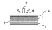
図1は、第1の例示的実施形態としての拡散反射型で動作する変換器の構造の概略側面図を示している。 FIG. 1 shows a schematic side view of the structure of a converter operating in a diffuse reflection type as a first exemplary embodiment.
この変換器は、オプトセラミックスとして形成された変換体1およびミラー3を含んでおり、変換体とミラーは接着層2によって相互に結合されている。変換材料のオプトセラミックスは、ドープされたYAGセラミックスまたはLuAGセラミックスであり、強散乱性の構造である。
This transducer includes a
矢印で示唆したように上の励起側から、出力密度の高い、つまり光線束断面が小さい青色の励起光4が変換体1の励起面に入射し、それからオプトセラミックス中に侵入することで、変換により長波の光5が生成され、そして散乱により外に放出される。
As suggested by the arrow, from the above excitation side,
接着層2は、例えば10μmの厚さdKlebを有している。ミラー3は、励起光4をオプトセラミックス1中に反射し、これにより、変換された比較的長波の光5の光収率を上昇させる。
The
例えば、変換面Aが4mm2であり、変換器の厚さdkonvが200μmである。最大ポンピング能力は下式で査定することができ、
Pmax opt≒4(Tmax Konv−TRT)/Rth
この場合、下式が適用され、
Tmax Konv=TRT+Q/A*d/λ
さらに変換器の熱抵抗Rth=d/(Aλ)および熱伝導度λで、Rth=d/(Aλ)である。
オプトセラミックスの熱伝導度λOC=10W/mK
接着剤の熱伝導度λKleb=0.3W/mK
For example, the conversion surface A is 4 mm 2 , and the thickness d komb of the converter is 200 μm. The maximum pumping ability can be assessed by the following formula,
P max opt ≈ 4 (T max Konv −T RT ) / R th
In this case, the following formula is applied
T max Konv = T RT + Q / A * d / λ
Further, the thermal resistance R th = d / (Aλ) and the thermal conductivity λ of the converter are R th = d / (Aλ).
Thermal conductivity of opt ceramics λ OC = 10W / mK
Thermal conductivity of adhesive λ Kleb = 0.3W / mK
変換器の熱抵抗は、変換材料および使用した接着剤の絶対的な熱抵抗Rthから分かる。 The thermal resistance of the transducer can be determined from the absolute thermal resistance Rth of the conversion material and the adhesive used.
したがって、オプトセラミックスの熱抵抗Rth OC=5K/Wおよび接着層の熱抵抗Rth Kleb=8.3K/Wでは、変換器に関し熱抵抗Rth Konvは13.3K/Wである。この場合は、接着層2がオプトセラミックス1より高い熱抵抗を示しており、したがって熱抵抗、つまりこの場合には熱抵抗の下限を決定的に規定している。
Therefore, the thermal resistance R th Kleb = 8.3K / W thermal resistance R th OC = 5K / W and the adhesive layer of optoceramics, the thermal resistance R th KONV relates converter is 13.3K / W. In this case, the
つまりオプトセラミックスの損傷閾値Tmax OC=250℃の場合、最大ポンピング能力Pmax optは68Wである。接着層は制限的にしか作用しない。 That is, when the damage threshold T max OC = 250 ° C. of the opt ceramics, the maximum pumping capacity P max opt is 68 W. The adhesive layer acts only in a limiting manner.
それでも接着剤の損傷閾値が100℃の場合、最大光ポンピング能力Pmax opt=36Wである。 Nevertheless, when the damage threshold of the adhesive is 100 ° C., the maximum optical pumping capacity P max opt = 36 W.
この驚くほど高いポンピング能力は、例えば4mm2に10Wで照射した場合に、輝度200cd/mm2および光束600lmを可能にする。 This surprisingly high pumping capacity allows for a brightness of 200 cd / mm 2 and a luminous flux of 600 lm, for example when irradiating 4 mm 2 with 10 W.
これに比べ、現況技術で知られているシリコーン中の発光物質、蛍光体イン・シリコーン(PIS)をベースとする変換器では、実現可能な最大光ポンピング能力Pmax optは約3Wである。これは、なかでも約100K/Wの高い熱抵抗Rth PISおよびPIS変換材料の低い損傷閾値のせいである。 In comparison, the maximum optical pumping capacity P max opt that can be achieved with a transducer based on phosphor-in-silicone (PIS), a luminescent substance in silicone known in the current technology, is about 3 W. This is due to the high thermal resistance R th PIS of about 100 K / W and the low damage threshold of the PIS conversion material.
図2は、第2の例示的実施形態の構造を概略的に示している。これは第1の例示的実施形態の一形式であり、この形式では追加的に、オプトセラミックス1上に反射防止コーティング6が施された。これにより、オプトセラミックス1の表面での励起放射線4の反射が低減され、散乱された変換光5の放出が改善される。
FIG. 2 schematically shows the structure of the second exemplary embodiment. This is one form of the first exemplary embodiment, in which an
図3は、第3の例示的実施形態の構造を示しており、背面励起、つまり透過性励起での変換器を示している。励起光4は、励起側11でオプトセラミックス1に当たる。放射側12では、変換された比較的長波の光5が出ていく。オプトセラミックス1の厚さは200マイクロメートルである。これにより、優れた量子効率での十分に高い透過が保証される。このオプトセラミックス1は、励起光の光スポットの横側で、つまり左および右でしか、金属のフレーム70によって固定されていない。したがってオプトセラミックス1の主な部分はこれらのフレームの間で宙に浮いている。この設計は、オプトセラミックス1が自立していることで初めて可能にされる。これとは異なりPISのような現況技術から知られている系は、土台、支持材料が必要であり、したがって背面励起は不可能である。フレーム70は放熱体として形成されており、2mmの直径を有している。放射点の大きさを小さくするため、オプトセラミックス1は放射側12でエッジフィルター91によりコーティングされている。励起側11も、オプトセラミックス1は広帯域のARコーティングでコーティングされている。
FIG. 3 shows the structure of a third exemplary embodiment, showing a transducer with backward excitation, i.e., transmissive excitation. The
図4に概略的に示した構造は、第3の例示的実施形態の一変形形態である。ここでのオプトセラミックス1は、励起光4の光スポットが入射する面を除いてオプトセラミックス1の下面の大部分がフレーム71で覆われるようにフレームで囲まれている。フレーム71は金属であり、励起光4および変換光5を含むオプトセラミックス1中で散乱された光を反射する。これによりオプトセラミックス中の光収率が上昇する。したがってここでは、励起側11でのオプトセラミックス1の追加的なコーティングをなくすことができる。
The structure schematically shown in FIG. 4 is a modification of the third exemplary embodiment. The opt-
第1の例示的実施形態の場合と同じ材料データを採用する場合、55K/Wの効果的な熱抵抗Rth effが生じる。これは、最大16Wの光ポンピング能力Pmax optを可能にする。 Adopting the same material data as in the first exemplary embodiment results in an effective thermal resistance R th eff of 55 K / W. This enables an optical pumping capability of up to 16 W P max opt .
この場合、第1の例示的実施形態の光ポンピング能力との差は、構造によって生み出されている。 In this case, the difference from the optical pumping capability of the first exemplary embodiment is created by the structure.
これに関し性能は、動作構成に応じて、例えば幾何学的要因にも左右される。このことが、透過型の最大ポンピング能力を拡散反射型より低くしている。 In this regard, performance depends, for example, on geometric factors, depending on the operating configuration. This makes the maximum pumping capacity of the transmission type lower than that of the diffuse reflection type.
下の表は、本発明による変換材料OC1およびOC2の、ならびにシリコーンまたはガラス/ガラスセラミックスに基づく変換材料の、静的変換器の熱的FOMに関する重要なデータの概要を示している。 The table below outlines important data on the thermal FOM of static transducers for converter materials OC1 and OC2 according to the present invention, as well as for conversion materials based on silicone or glass / glass ceramics.
静的に動作する変換器に関する熱的FOMは、最大限許容される温度と熱伝導度の積である。 The thermal FOM for a statically operating transducer is the product of the maximum permissible temperature and thermal conductivity.
本発明による変換器は最大7322W/mのFOMstatを示し、これに対し類似の構造でのシリコーン中の発光物質による現況技術の変換器は95W/mのFOMしかない。 Converter according to the invention is up to 7322W / m indicates the FOM stat, which converter state of the art by the luminescent material in the silicone in a similar structure to have only FOM of 95W / m.
最後の欄ではFOMに蓄熱量を付け加えた。この蓄熱量とは熱容量と密度の積である。このように追補されたFOM、FOMdynは、回転するホイール上の変換器の挙動を表し、つまり動的変換器に関している。 In the last column, the amount of heat storage was added to FOM. This amount of heat storage is the product of heat capacity and density. The FOM and FOM dyne supplemented in this way represent the behavior of the transducer on the rotating wheel, that is, the dynamic transducer.
本発明によるオプトセラミックスOC1およびOC2は、並はずれて高いFOMを示している。 The optoceramics OC1 and OC2 according to the present invention exhibit exceptionally high FOM.
両方のオプトセラミックスOC1およびOC2は、そのドーピングに違いがある。オプトセラミックスOC1はYAG(イットリウム・アルミニウム・ガーネット)を含有しており、オプトセラミックスOC2はMg3Al8[SiO]3を含有している。 Both optoceramics OC1 and OC2 differ in their doping. Opt-ceramics OC1 contains YAG (yttrium aluminum garnet), and opt-ceramics OC2 contains Mg 3 Al 8 [SiO] 3 .
ただし両方のオプトセラミックスのFOMの差は、なかでも密度の違いが原因と考えられる。 However, the difference in FOM between both optoceramics is considered to be due to the difference in density.
表に挙げた材料は、FOMに関して3つのグループに分けることができる。シリコーンマトリックスをベースとする変換器の低いFOMは、なかでも熱伝導度の低さが原因と考えられる。 The materials listed in the table can be divided into three groups with respect to FOM. The low FOM of the silicone matrix-based transducer is considered to be due in particular to its low thermal conductivity.
ガラスまたはガラスセラミックスをベースとする材料は、シリコーンマトリックスの、つまり有機系のFOMより明らかに高いFOMを示している。しかしながら本発明によるオプトセラミックスのFOMは、ガラスセラミックスをベースとする変換器のFOMの5倍超である。 Materials based on glass or glass ceramics exhibit a significantly higher FOM than the silicone matrix, or organic FOM. However, the FOM of opt-ceramics according to the present invention is more than five times that of the FOM of a glass ceramic-based transducer.
なかでも、オプトセラミックスが格別に高い熱伝導度λを示すことが有利である。 Above all, it is advantageous that the opt ceramics exhibit an exceptionally high thermal conductivity λ.

図5に示した第5の例示的実施形態は、拡散反射型で動作する動的変換器の断面を概略的に示している。オプトセラミックス1は円形のディスクとして形成されており、接着層2により支持体3上に施されている。オプトセラミックス1の表面はエッジフィルター9でコーティングされている。支持体3は中心でハブ8と結合している。励起は、局所的に変換器の一部位に制限されて行われる。ハブ8により、支持体3はオプトセラミックス1と一緒に回転する。したがって、オプトセラミックス1の所定の局所的な一領域は、短時間しか励起光4で照射されない。局所的な照射時間は、ハブ8の回転周波数を介して調整することができる。短く局所的な照射時間により、25Wをはるかに超える高い励起出力を実現することができる。
The fifth exemplary embodiment shown in FIG. 5 schematically illustrates a cross section of a dynamic transducer operating in a diffuse reflection manner. The
図6に概略的に図示した例示的実施形態では、オプトセラミックス1がリングとして形成されており、接着層2により円形の支持体3上に取り付けられている。リング状のオプトセラミックス1の使用は、比較的少ない材料消費を可能にし、それでも変換器の光学特性には影響を及ぼさない。これが可能なのは、この実施形態ではどのみち励起放射線4が当たらない領域だけを除去しているからである。
In the exemplary embodiment schematically illustrated in FIG. 6, the opt-
図7は、透過型の動的な、つまり回転する変換器の概略図を示している。ディスク状の支持体3にリング状のオプトセラミックス1が固定されており、この支持体は反射性のフレームとして形成されている。この場合、支持体3は、オプトセラミックスを固定するのに必要なだけしかオプトセラミックス1の下面によって覆われていない。オプトセラミックスの下面の主な部分は支持体3に覆い隠されておらず、したがって変換に利用することができる。
FIG. 7 shows a schematic of a transmissive, dynamic, or rotating, transducer. A ring-shaped
オプトセラミックス1はここでも、励起側、つまりオプトセラミックスの下面にARコーティング10を、およびオプトセラミックスの上面にはエッジフィルター91を備えている。
Again, the opt-ceramic 1 is provided with an
図8は、量子効率と拡散反射の関係を示している。ただし変換器の散乱特性を定量化するため、散乱と拡散反射の関係を利用できることが有利である。このため励起波長より長い波長で拡散反射を測定する。この場合、1mm厚の変換材料の試料の拡散反射を600nmの波長で測定した。分光計として積分球を備えた分光計を利用した。以下では、この測定ルールに基づいて測定した拡散反射REmissionを、散乱特性の光学測定の代わりとする。ここでは1mm厚の試料に基づき、波長600nmでの拡散反射を決定した。この場合、強散乱性の材料は高い拡散反射を示す。 FIG. 8 shows the relationship between quantum efficiency and diffuse reflection. However, in order to quantify the scattering characteristics of the converter, it is advantageous to be able to utilize the relationship between scattering and diffuse reflection. Therefore, the diffuse reflection is measured at a wavelength longer than the excitation wavelength. In this case, the diffuse reflection of the sample of the conversion material having a thickness of 1 mm was measured at a wavelength of 600 nm. A spectrometer equipped with an integrating sphere was used as the spectrometer. In the following, the diffuse reflection R Emission measured based on this measurement rule will be used as a substitute for the optical measurement of the scattering characteristics. Here, the diffuse reflection at a wavelength of 600 nm was determined based on a sample having a thickness of 1 mm. In this case, the strongly scatterable material exhibits high diffuse reflection.
予測では、強散乱性の試料の場合には量子効率は低下する。この予測された挙動がグラフに直線で示されている。 Prediction is that quantum efficiency is reduced for strongly scatterable samples. This predicted behavior is shown in a straight line on the graph.
しかしながら非常に驚くべきことに、試料が高い拡散反射を示す場合に量子効率が有意に低下しない体系14を確定することができた。
However, very surprisingly, we were able to establish a
つまり、600nmでの拡散反射が0.7〜0.95で、量子効率が0.85を上回るオプトセラミックスが形成された。 That is, optoceramics having a diffuse reflection at 600 nm of 0.7 to 0.95 and a quantum efficiency of more than 0.85 were formed.
これに関し本発明によるオプトセラミックスのこの異例の特性は、出発混合物の特殊な組成および製造条件の結果である。驚くべきことに、オプトセラミックスの散乱は、焼結温度の選択により調整できることが分かった。これを以下に図9および図10に示した例に基づいて説明する。図9および図10は、2種の異なる組成のセリウムドープされたオプトセラミックスの拡散反射、量子効率、および拡散反射と量子効率の積の依存性を示している。 In this regard, this unusual property of optoceramics according to the invention is a result of the special composition and manufacturing conditions of the starting mixture. Surprisingly, it was found that the scattering of optoceramics can be adjusted by selecting the sintering temperature. This will be described below with reference to the examples shown in FIGS. 9 and 10. 9 and 10 show the diffuse reflection, quantum efficiency, and the product dependency of diffuse reflection and quantum efficiency of two different compositions of cerium-doped optoceramics.
これに関し図9は、組成Lu3(Ga、Al)5O12−Ceのオプトセラミックスの複合グラフを示しており、図10でのオプトセラミックスの組成はY3Al5O12−Ceである。 In this regard, FIG. 9 shows a composite graph of opt-ceramics having a composition of Lu 3 (Ga, Al) 5 O 12- Ce, and the composition of the opt-ceramics in FIG. 10 is Y 3 Al 5 O 12- Ce.
両方の場合に、拡散反射は焼結温度に依存しており、その一方でこの依存性が量子効率の場合には弱くしか現れていない。これは、特に図9で明らかである。 In both cases, diffuse reflection depends on the sintering temperature, while this dependence appears weakly in the case of quantum efficiency. This is especially apparent in FIG.
すなわち焼結温度の100℃の上昇は、拡散反射を半減させ、その一方で量子効率はほぼ一定のままである。 That is, a 100 ° C increase in sintering temperature halves the diffuse reflection, while the quantum efficiency remains nearly constant.
図10に示したように、この効果は第2のオプトセラミックスではかなり弱く現れている。 As shown in FIG. 10, this effect appears fairly weak in the second opt ceramics.
効果の現れは、なかでも出発材料の組成に依存し得る。つまり両方の値の関係は、変換中心の密度、つまりドーピング度に依存している。 The manifestation of the effect may depend, among other things, on the composition of the starting material. In other words, the relationship between both values depends on the density of the conversion center, that is, the degree of doping.
図11は、Ce2O3のドーピング度が異なる本発明によるオプトセラミックスの、吸収効率と拡散反射つまり散乱の間の依存性を示している。 FIG. 11 shows the dependence between absorption efficiency and diffuse reflection or scattering of optoceramics according to the present invention with different degrees of doping of Ce 2 O 3 .
吸収効率は、入射した励起光に対する吸収された励起光の割合を表す。吸収効率は、青色の励起光の拡散反射から、1−R_Excitationに基づいて算出される。青色の励起光の拡散反射は、量子効率の測定場所で1mm厚の試料に対して測定した。 Absorption efficiency represents the ratio of absorbed excitation light to incident excitation light. The absorption efficiency is calculated from the diffuse reflection of the blue excitation light based on 1-R_Excitation. The diffuse reflection of the blue excitation light was measured for a 1 mm thick sample at the quantum efficiency measurement site.
高いドーピング度(0.2wt% Ce2O3)でのオプトセラミックスは、吸収効率と拡散反射の強い依存性を示している。なかでも0.8以上の高い拡散反射値では、吸収効率が急激に低下している。 Optoceramics at high doping degrees (0.2 wt% Ce 2 O 3 ) show a strong dependence on absorption efficiency and diffuse reflection. Above all, at a high diffuse reflection value of 0.8 or more, the absorption efficiency drops sharply.
青色の光の吸収効率つまり青色の拡散反射R_Excitationは、散乱つまり黄色の拡散反射R_Emissionの調整により、広い範囲内で調整できることが分かる。 It can be seen that the blue light absorption efficiency, that is, the blue diffuse reflection R_Exclusion, can be adjusted within a wide range by adjusting the scattering, that is, the yellow diffuse reflection R_Emission.
量子効率にほとんど依存しない散乱の調整により、一方では優れた光閉じ込め、したがって高輝度を達成することができる。 By adjusting the scattering, which is largely independent of quantum efficiency, good light confinement, and thus high brightness, can be achieved on the one hand.
もう一方で、拡散反射された励起放射R_Excitationと変換された光の放射の混合が色の位置のグラフにおける変換直線上の特定の色感覚を生じさせるように、散乱を調整することができる。変換直線とは、励起光の色の位置と放射スペクトルの色の位置の間を結ぶ線である。 On the other hand, the scattering can be adjusted so that the mixture of the diffusely reflected excitation radiation R_Excitation and the converted light radiation produces a particular color sensation on the conversion line in the color position graph. The conversion straight line is a line connecting the color position of the excitation light and the color position of the emission spectrum.
図12に基づき、色スペクトルのグラフにおける白色エリア付近の点の調整を可能にするさらなる1つの例示的実施形態を説明する。拡散反射型動作のため、変換器1がミラー31を備えているとする。色スペクトルのグラフにおける変換直線上の白色エリアの付近に達するには、青色の励起光の20%を拡散反射し、80%を吸収するように、変換器1の散乱特性を選択する。励起光の吸収された部分は大部分が黄色の光に変換され、直接的に、またはミラー31で反射された後に、散乱ローブ(scattering lobe)51として放射される。
With reference to FIG. 12, one additional exemplary embodiment that allows adjustment of points near the white area in the color spectrum graph will be described. It is assumed that the
青色の拡散反射光は、フレネル反射40および散乱ローブ41から構成されている。この散乱ローブ41はランベルトの放射特性を示している。
The blue diffuse reflected light is composed of the
ここで変換器厚さの調整により、白色エリア付近の点のシフトを行う。この変換器厚さが、励起光がミラー31で反射されて表面で再び出ていくほど小さければ、第2の散乱ローブ42が生じる。この第2の散乱ローブ42は、変換器厚さおよび散乱に応じ、多かれ少なかれ指向性の放射特性を有している。励起光の散乱ローブ40、41、42および変換された光の散乱ローブ51が重なることにより、色感覚の角度依存性が生じる。
Here, the points near the white area are shifted by adjusting the thickness of the converter. If the transducer thickness is small enough that the excitation light is reflected by the
この角度依存性は、変換器表面を粗面化することで低減させることができる。 This angle dependence can be reduced by roughening the surface of the transducer.
代替策として、白色エリア付近の点に達するための精密適合を、変換器1の励起側で薄い散乱層を塗布することにより行うことができる。この散乱層は、例えばTiO2またはドープされていないオプトセラミックス材料から成ることができる。両方の場合に、放射光の青色割合が黄色割合に対して上昇される。色の位置のグラフの白色エリア内に達するため、緑色部分での黄色の光をフィルタリングによって取り除くことができる。これは、例えばダイクロイックミラーによって達成することができ、このダイクロイックミラーは、青色の光は反射するが、緑色の光が当たると通過させ、したがって緑色の光は変換器の利用側では出ていかない。
As an alternative, precision adaptation to reach a point near the white area can be achieved by applying a thin scattering layer on the excitation side of the
本発明による変換材料は、オーダーメイドの熱特性、熱・光特性、および光特性を示す。 The conversion material according to the present invention exhibits bespoke thermal, thermal / optical, and optical properties.
これらの特性の相乗作用が、100cd/mm2超の非常に高い輝度を可能にする。 The synergistic action of these properties allows for very high brightness above 100 cd / mm 2 .
Claims (11)
− 前記励起光に対向する励起面と前記励起光から背けられた面とを備えた、変換材料から成る変換体(1)を含んでおり、前記面の互いの間隔が前記変換体(1)の厚さを規定しており、
− 前記変換材料が、ドープされたLuAGセラミックスから成るオプトセラミックスであり、前記変換材料が、セリウムでドーピングされており、該ドーピングの量が0.01〜2%の範囲内であり、前記オプトセラミックスが、前記励起光(4)の光線束断面と同等な空間的に小さな放射点を生成するために、前記励起面に入射する前記励起光(4)が前記変換体(1)の内部で強く散乱されて光閉じ込めにおいて比較的長波の光(5)に変換する粒状構造を備えており、拡散反射された前記励起光(4)および拡散反射された前記比較的長波の光(5)の割合を適合させるために前記変換体(1)の前記厚さを利用可能であり、拡散反射Remissionは少なくとも60%であり、
1mm厚の変換器での強い散乱が、波長600nmの長波光の拡散反射係数、拡散反射Remission>0.6を生じさせ、
量子効率QEが0.80よりも大きい、ことを特徴とする変換器。 A converter for generating high-intensity colored light or white light from (blue) excitation light (4) that exists as a light bundle and generates small bright spots on the converter, and the converter is ,
− A transformant (1) made of a conversion material having an excitation surface facing the excitation light and a surface turned away from the excitation light is included, and the distance between the surfaces is the transformant (1). Specifies the thickness of
-The conversion material is opt ceramics composed of doped LuAG ceramics, the conversion material is doped with cerium, the amount of doping is in the range of 0.01 to 2%, and the opt ceramics. However, in order to generate a spatially small radiation point equivalent to the light bundle cross section of the excitation light (4), the excitation light (4) incident on the excitation surface is strongly generated inside the transformant (1). It has a granular structure that is scattered and converted into relatively long-wave light (5) in light confinement, and the ratio of the diffuse-reflected excitation light (4) and the diffuse-reflected relatively long-wave light (5). the available the thickness of the converter (1) in order to adapt, diffuse reflection R emission is at least 60%,
Strong scattering in 1mm thickness transducers, diffuse reflection coefficient of the long wave light having a wavelength of 600 nm, causing diffuse reflection R emission> 0.6,
A converter characterized in that the quantum efficiency QE is larger than 0.80.
Applications Claiming Priority (7)
| Application Number | Priority Date | Filing Date | Title |
|---|---|---|---|
| DE102011116826 | 2011-10-25 | ||
| DE102011116826.9 | 2011-10-25 | ||
| US201261614061P | 2012-03-22 | 2012-03-22 | |
| US61/614,061 | 2012-03-22 | ||
| DE102012005654.0 | 2012-03-22 | ||
| DE102012005654.0A DE102012005654B4 (en) | 2011-10-25 | 2012-03-22 | Optical converter for high luminance levels |
| PCT/EP2012/071069 WO2013060731A2 (en) | 2011-10-25 | 2012-10-24 | Optical converter for high luminances |
Related Child Applications (1)
| Application Number | Title | Priority Date | Filing Date |
|---|---|---|---|
| JP2018146885A Division JP6761006B2 (en) | 2011-10-25 | 2018-08-03 | High brightness optical converter |
Publications (3)
| Publication Number | Publication Date |
|---|---|
| JP2015503180A JP2015503180A (en) | 2015-01-29 |
| JP2015503180A5 JP2015503180A5 (en) | 2015-12-03 |
| JP6754548B2 true JP6754548B2 (en) | 2020-09-16 |
Family
ID=48051386
Family Applications (2)
| Application Number | Title | Priority Date | Filing Date |
|---|---|---|---|
| JP2014537598A Active JP6754548B2 (en) | 2011-10-25 | 2012-10-24 | High brightness optical converter |
| JP2018146885A Active JP6761006B2 (en) | 2011-10-25 | 2018-08-03 | High brightness optical converter |
Family Applications After (1)
| Application Number | Title | Priority Date | Filing Date |
|---|---|---|---|
| JP2018146885A Active JP6761006B2 (en) | 2011-10-25 | 2018-08-03 | High brightness optical converter |
Country Status (6)
| Country | Link |
|---|---|
| US (1) | US9738828B2 (en) |
| EP (1) | EP2771430A2 (en) |
| JP (2) | JP6754548B2 (en) |
| CN (2) | CN103906822A (en) |
| DE (1) | DE102012005654B4 (en) |
| WO (1) | WO2013060731A2 (en) |
Families Citing this family (14)
| Publication number | Priority date | Publication date | Assignee | Title |
|---|---|---|---|---|
| DE102012005658B4 (en) | 2012-03-22 | 2013-10-24 | Schott Ag | White light generation |
| DE102013200989A1 (en) * | 2013-01-22 | 2014-07-24 | Osram Gmbh | Color wheel for a lighting device |
| JP6131109B2 (en) * | 2013-06-10 | 2017-05-17 | シャープ株式会社 | Light emitting device and display device |
| DE102013013296B4 (en) * | 2013-08-12 | 2020-08-06 | Schott Ag | Converter-heat sink assembly with metallic solder connection and method for its production |
| DE102013218451A1 (en) * | 2013-09-14 | 2015-03-19 | Fraunhofer-Gesellschaft zur Förderung der angewandten Forschung e.V. | Conversion element for an optical or optoelectronic component and method for its production |
| US20150219870A1 (en) * | 2014-01-31 | 2015-08-06 | Christie Digital Systems Usa, Inc. | Light emitting wheel with eccentricity for dispelling a thermal boundary layer |
| DE102014102350B4 (en) | 2014-02-24 | 2016-03-03 | Schott Ag | Converter arrangement with cooling for light sources with high luminance |
| WO2015138495A1 (en) * | 2014-03-11 | 2015-09-17 | Osram Sylvania Inc. | Light converter assemblies with enhanced heat dissipation |
| CN105738994B (en) * | 2014-12-10 | 2019-07-02 | 深圳光峰科技股份有限公司 | Wavelength converter and related lighting device, fluorescence colour wheel and projection arrangement |
| US10712331B2 (en) * | 2015-10-23 | 2020-07-14 | Novartis Ag | Computer method and system for deriving cell-to-cell spatial proximities |
| JP6852976B2 (en) * | 2016-03-29 | 2021-03-31 | 日本特殊陶業株式会社 | Wavelength conversion member, its manufacturing method and light emitting device |
| EP3678266A4 (en) * | 2017-08-28 | 2020-09-23 | Panasonic Intellectual Property Management Co., Ltd. | Light emitting device |
| DE102022113940A1 (en) | 2022-06-02 | 2023-12-07 | Schott Ag | Method for determining a thermal quality measure of a test specimen |
| DE102022120654B4 (en) | 2022-08-16 | 2024-03-28 | Schott Ag | Lighting device |
Family Cites Families (35)
| Publication number | Priority date | Publication date | Assignee | Title |
|---|---|---|---|---|
| DE3026605C2 (en) | 1980-07-14 | 1983-07-07 | Schott Glaswerke, 6500 Mainz | Acid-proof, hydrolytically stable optical and ophthalmic borosilicate glass of low density |
| DE19942014A1 (en) * | 1999-09-03 | 2001-03-08 | Eastman Kodak Co | Compact color digital image projector light source, improving image for lower current consumption, follows low power electroluminescent image generator by image intensifier |
| JP4158012B2 (en) * | 2002-03-06 | 2008-10-01 | 日本電気硝子株式会社 | Luminescent color conversion member |
| US7554258B2 (en) * | 2002-10-22 | 2009-06-30 | Osram Opto Semiconductors Gmbh | Light source having an LED and a luminescence conversion body and method for producing the luminescence conversion body |
| US6953536B2 (en) * | 2003-02-25 | 2005-10-11 | University Of Georgia Research Foundation, Inc. | Long persistent phosphors and persistent energy transfer technique |
| JP2005272486A (en) * | 2004-03-22 | 2005-10-06 | Fujikura Ltd | POWDER PHOSPHOR, METHOD FOR PRODUCING alpha-SIALON PHOSPHOR AND LIGHT-EMITTING DEVICE |
| US7380962B2 (en) * | 2004-04-23 | 2008-06-03 | Light Prescriptions Innovators, Llc | Optical manifold for light-emitting diodes |
| US7361938B2 (en) * | 2004-06-03 | 2008-04-22 | Philips Lumileds Lighting Company Llc | Luminescent ceramic for a light emitting device |
| WO2006072918A1 (en) * | 2005-01-10 | 2006-07-13 | Philips Intellectual Property & Standards Gmbh | Illumination system comprising ceramic luminescence converter |
| JP5490407B2 (en) * | 2005-03-14 | 2014-05-14 | コーニンクレッカ フィリップス エヌ ヴェ | Phosphor having a polycrystalline ceramic structure, and light emitting device having the phosphor |
| DE102005023134A1 (en) * | 2005-05-19 | 2006-11-23 | Patent-Treuhand-Gesellschaft für elektrische Glühlampen mbH | Luminescence conversion LED |
| US7196354B1 (en) * | 2005-09-29 | 2007-03-27 | Luminus Devices, Inc. | Wavelength-converting light-emitting devices |
| US7514721B2 (en) * | 2005-11-29 | 2009-04-07 | Koninklijke Philips Electronics N.V. | Luminescent ceramic element for a light emitting device |
| JP5049336B2 (en) * | 2006-03-21 | 2012-10-17 | コーニンクレッカ フィリップス エレクトロニクス エヌ ヴィ | Electroluminescent device |
| JP2007273498A (en) * | 2006-03-30 | 2007-10-18 | Kyocera Corp | Wavelength converter and light emitting device |
| JP2008084908A (en) * | 2006-09-26 | 2008-04-10 | Toshiba Lighting & Technology Corp | Light emitting device |
| JP2010509751A (en) * | 2006-11-07 | 2010-03-25 | コーニンクレッカ フィリップス エレクトロニクス エヌ ヴィ | Device for emitting mixed light |
| US7700967B2 (en) * | 2007-05-25 | 2010-04-20 | Philips Lumileds Lighting Company Llc | Illumination device with a wavelength converting element held by a support structure having an aperture |
| US7547114B2 (en) | 2007-07-30 | 2009-06-16 | Ylx Corp. | Multicolor illumination device using moving plate with wavelength conversion materials |
| CN101393312A (en) | 2007-09-19 | 2009-03-25 | 鸿富锦精密工业(深圳)有限公司 | Color wheel |
| US8728835B2 (en) | 2008-01-15 | 2014-05-20 | Koninklijke Philips N.V. | Light scattering by controlled porosity in optical ceramics for LEDs |
| DE102008017071A1 (en) * | 2008-01-31 | 2009-08-06 | Osram Opto Semiconductors Gmbh | Optoelectronic module and projection device with the optoelectronic module |
| CN101939857B (en) * | 2008-02-07 | 2013-05-15 | 三菱化学株式会社 | Semiconductor light emitting device, backlight, color image display device and phosphor to be used for them |
| JP5311281B2 (en) * | 2008-02-18 | 2013-10-09 | 日本電気硝子株式会社 | Wavelength conversion member and manufacturing method thereof |
| WO2009115976A1 (en) | 2008-03-20 | 2009-09-24 | Koninklijke Philips Electronics N.V. | Illumination system comprising a luminescent element with a heat sink |
| WO2009119034A1 (en) * | 2008-03-26 | 2009-10-01 | Panasonic Corporation | Semiconductor light-emitting apparatus |
| DE102008021438A1 (en) * | 2008-04-29 | 2009-12-31 | Schott Ag | Conversion material in particular for a, a semiconductor light source comprising white or colored light source, method for its preparation and this conversion material comprising light source |
| KR20110031994A (en) * | 2008-07-22 | 2011-03-29 | 코닌클리즈케 필립스 일렉트로닉스 엔.브이. | An optical element for a light emitting device and a method of manufacturing thereof |
| JP2010092705A (en) * | 2008-10-08 | 2010-04-22 | Sony Corp | Illuminating device and display device using this |
| JP5689225B2 (en) * | 2009-03-31 | 2015-03-25 | 日亜化学工業株式会社 | Light emitting device |
| JP5397944B2 (en) * | 2009-11-11 | 2014-01-22 | 日東電工株式会社 | Phosphor-containing composite sheet |
| JP5530165B2 (en) * | 2009-12-17 | 2014-06-25 | スタンレー電気株式会社 | Light source device and lighting device |
| US20110186874A1 (en) * | 2010-02-03 | 2011-08-04 | Soraa, Inc. | White Light Apparatus and Method |
| WO2011097137A1 (en) * | 2010-02-04 | 2011-08-11 | Nitto Denko Corporation | Light emissive ceramic laminate and method of making same |
| JP4740379B1 (en) * | 2010-02-25 | 2011-08-03 | 電気化学工業株式会社 | β-type sialon phosphor, its use and method for producing β-type sialon phosphor |
-
2012
- 2012-03-22 DE DE102012005654.0A patent/DE102012005654B4/en active Active
- 2012-10-24 CN CN201280052795.XA patent/CN103906822A/en active Pending
- 2012-10-24 JP JP2014537598A patent/JP6754548B2/en active Active
- 2012-10-24 EP EP12784532.9A patent/EP2771430A2/en not_active Withdrawn
- 2012-10-24 WO PCT/EP2012/071069 patent/WO2013060731A2/en active Application Filing
- 2012-10-24 CN CN201810558154.0A patent/CN108753292A/en active Pending
-
2014
- 2014-04-25 US US14/262,064 patent/US9738828B2/en active Active
-
2018
- 2018-08-03 JP JP2018146885A patent/JP6761006B2/en active Active
Also Published As
| Publication number | Publication date |
|---|---|
| WO2013060731A2 (en) | 2013-05-02 |
| WO2013060731A3 (en) | 2014-01-16 |
| CN108753292A (en) | 2018-11-06 |
| JP2018185542A (en) | 2018-11-22 |
| US20150070907A1 (en) | 2015-03-12 |
| US9738828B2 (en) | 2017-08-22 |
| JP2015503180A (en) | 2015-01-29 |
| CN103906822A (en) | 2014-07-02 |
| DE102012005654B4 (en) | 2021-03-04 |
| JP6761006B2 (en) | 2020-09-23 |
| DE102012005654A1 (en) | 2013-04-25 |
| EP2771430A2 (en) | 2014-09-03 |
Similar Documents
| Publication | Publication Date | Title |
|---|---|---|
| JP6761006B2 (en) | High brightness optical converter | |
| JP6225338B2 (en) | Light source and image projection device | |
| US8931922B2 (en) | Ceramic wavelength-conversion plates and light sources including the same | |
| JP6968339B2 (en) | Fluorescent light source device | |
| JP2012243624A (en) | Light source device and lighting device | |
| JP5675248B2 (en) | Light source device and lighting device | |
| JP2012064484A (en) | Light source device | |
| JPWO2017038164A1 (en) | Light emitting device | |
| JP2012089316A (en) | Light source device, and lighting system | |
| JP2019066880A (en) | Phosphor, wavelength conversion element, light source device, and projector | |
| JP2012099222A (en) | Light source device and lighting device | |
| KR20210041539A (en) | Specular color correction for phosphor lighting systems | |
| CN107110440B (en) | Fluorescent light source device | |
| TWI810280B (en) | High efficiency and uniformity white light generator stimulated by laser | |
| JP2019039992A (en) | Phosphor wheel, wheel device and projector | |
| JP2012079989A (en) | Light source device and lighting fixture | |
| JP2017147049A (en) | Light-emitting device | |
| US20220136679A1 (en) | Wavelength conversion element, light source device, vehicle headlight, transmissive lighting device, display device, and lighting device | |
| JP5781367B2 (en) | Light source device and lighting device | |
| WO2019230935A1 (en) | Wavelength conversion element, light source device, vehicle headlamp, display device, light source module, and projection device | |
| CN112639545A (en) | Wavelength conversion member, and light source device, projector, and vehicle using same | |
| JPWO2019004064A1 (en) | Phosphor layer composition, fluorescent member, light source device and projection device | |
| WO2020090663A1 (en) | Optical element, fluorescent wheel, light source device, headlight for vehicles, and projection device | |
| WO2020189405A1 (en) | Optical element, vehicle headlight, light source device, and projection device | |
| CN111965929A (en) | Novel total reflection type fluorescent wheel device |
Legal Events
| Date | Code | Title | Description |
|---|---|---|---|
| A521 | Request for written amendment filed |
Free format text: JAPANESE INTERMEDIATE CODE: A523 Effective date: 20151016 |
|
| A621 | Written request for application examination |
Free format text: JAPANESE INTERMEDIATE CODE: A621 Effective date: 20151016 |
|
| A977 | Report on retrieval |
Free format text: JAPANESE INTERMEDIATE CODE: A971007 Effective date: 20160818 |
|
| A131 | Notification of reasons for refusal |
Free format text: JAPANESE INTERMEDIATE CODE: A131 Effective date: 20160825 |
|
| A521 | Request for written amendment filed |
Free format text: JAPANESE INTERMEDIATE CODE: A523 Effective date: 20161124 |
|
| A131 | Notification of reasons for refusal |
Free format text: JAPANESE INTERMEDIATE CODE: A131 Effective date: 20170509 |
|
| A601 | Written request for extension of time |
Free format text: JAPANESE INTERMEDIATE CODE: A601 Effective date: 20170809 |
|
| A521 | Request for written amendment filed |
Free format text: JAPANESE INTERMEDIATE CODE: A523 Effective date: 20171109 |
|
| A02 | Decision of refusal |
Free format text: JAPANESE INTERMEDIATE CODE: A02 Effective date: 20180403 |
|
| A521 | Request for written amendment filed |
Free format text: JAPANESE INTERMEDIATE CODE: A523 Effective date: 20180803 |
|
| A911 | Transfer to examiner for re-examination before appeal (zenchi) |
Free format text: JAPANESE INTERMEDIATE CODE: A911 Effective date: 20180918 |
|
| A912 | Re-examination (zenchi) completed and case transferred to appeal board |
Free format text: JAPANESE INTERMEDIATE CODE: A912 Effective date: 20181130 |
|
| A601 | Written request for extension of time |
Free format text: JAPANESE INTERMEDIATE CODE: A601 Effective date: 20191016 |
|
| A521 | Request for written amendment filed |
Free format text: JAPANESE INTERMEDIATE CODE: A523 Effective date: 20200116 |
|
| A521 | Request for written amendment filed |
Free format text: JAPANESE INTERMEDIATE CODE: A523 Effective date: 20200602 |
|
| A61 | First payment of annual fees (during grant procedure) |
Free format text: JAPANESE INTERMEDIATE CODE: A61 Effective date: 20200824 |
|
| R150 | Certificate of patent or registration of utility model |
Ref document number: 6754548 Country of ref document: JP Free format text: JAPANESE INTERMEDIATE CODE: R150 |
|
| R250 | Receipt of annual fees |
Free format text: JAPANESE INTERMEDIATE CODE: R250 |