JP6747402B2 - Blower - Google Patents
Blower Download PDFInfo
- Publication number
- JP6747402B2 JP6747402B2 JP2017156251A JP2017156251A JP6747402B2 JP 6747402 B2 JP6747402 B2 JP 6747402B2 JP 2017156251 A JP2017156251 A JP 2017156251A JP 2017156251 A JP2017156251 A JP 2017156251A JP 6747402 B2 JP6747402 B2 JP 6747402B2
- Authority
- JP
- Japan
- Prior art keywords
- fan
- space
- air
- fluid
- blower
- Prior art date
- Legal status (The legal status is an assumption and is not a legal conclusion. Google has not performed a legal analysis and makes no representation as to the accuracy of the status listed.)
- Active
Links
- 239000012530 fluid Substances 0.000 claims description 62
- 238000005192 partition Methods 0.000 claims description 37
- 238000007664 blowing Methods 0.000 claims description 4
- 239000005357 flat glass Substances 0.000 description 9
- 239000000470 constituent Substances 0.000 description 5
- 238000011144 upstream manufacturing Methods 0.000 description 4
- 238000001816 cooling Methods 0.000 description 3
- 238000010438 heat treatment Methods 0.000 description 3
- 238000000034 method Methods 0.000 description 3
- 230000000694 effects Effects 0.000 description 2
- 239000011347 resin Substances 0.000 description 2
- 229920005989 resin Polymers 0.000 description 2
- 238000000638 solvent extraction Methods 0.000 description 2
- 238000004378 air conditioning Methods 0.000 description 1
- 230000006835 compression Effects 0.000 description 1
- 238000007906 compression Methods 0.000 description 1
- 239000000498 cooling water Substances 0.000 description 1
- 230000007423 decrease Effects 0.000 description 1
- 239000007769 metal material Substances 0.000 description 1
- 238000012986 modification Methods 0.000 description 1
- 230000004048 modification Effects 0.000 description 1
- 238000005057 refrigeration Methods 0.000 description 1
- 230000003068 static effect Effects 0.000 description 1
- 238000009423 ventilation Methods 0.000 description 1
Images


Classifications
-
- F—MECHANICAL ENGINEERING; LIGHTING; HEATING; WEAPONS; BLASTING
- F04—POSITIVE - DISPLACEMENT MACHINES FOR LIQUIDS; PUMPS FOR LIQUIDS OR ELASTIC FLUIDS
- F04D—NON-POSITIVE-DISPLACEMENT PUMPS
- F04D17/00—Radial-flow pumps, e.g. centrifugal pumps; Helico-centrifugal pumps
- F04D17/08—Centrifugal pumps
- F04D17/10—Centrifugal pumps for compressing or evacuating
-
- F—MECHANICAL ENGINEERING; LIGHTING; HEATING; WEAPONS; BLASTING
- F04—POSITIVE - DISPLACEMENT MACHINES FOR LIQUIDS; PUMPS FOR LIQUIDS OR ELASTIC FLUIDS
- F04D—NON-POSITIVE-DISPLACEMENT PUMPS
- F04D29/00—Details, component parts, or accessories
- F04D29/26—Rotors specially for elastic fluids
- F04D29/28—Rotors specially for elastic fluids for centrifugal or helico-centrifugal pumps for radial-flow or helico-centrifugal pumps
- F04D29/281—Rotors specially for elastic fluids for centrifugal or helico-centrifugal pumps for radial-flow or helico-centrifugal pumps for fans or blowers
- F04D29/282—Rotors specially for elastic fluids for centrifugal or helico-centrifugal pumps for radial-flow or helico-centrifugal pumps for fans or blowers the leading edge of each vane being substantially parallel to the rotation axis
-
- B—PERFORMING OPERATIONS; TRANSPORTING
- B60—VEHICLES IN GENERAL
- B60H—ARRANGEMENTS OF HEATING, COOLING, VENTILATING OR OTHER AIR-TREATING DEVICES SPECIALLY ADAPTED FOR PASSENGER OR GOODS SPACES OF VEHICLES
- B60H1/00—Heating, cooling or ventilating [HVAC] devices
-
- B—PERFORMING OPERATIONS; TRANSPORTING
- B60—VEHICLES IN GENERAL
- B60H—ARRANGEMENTS OF HEATING, COOLING, VENTILATING OR OTHER AIR-TREATING DEVICES SPECIALLY ADAPTED FOR PASSENGER OR GOODS SPACES OF VEHICLES
- B60H1/00—Heating, cooling or ventilating [HVAC] devices
- B60H1/00007—Combined heating, ventilating, or cooling devices
- B60H1/00021—Air flow details of HVAC devices
-
- B—PERFORMING OPERATIONS; TRANSPORTING
- B60—VEHICLES IN GENERAL
- B60H—ARRANGEMENTS OF HEATING, COOLING, VENTILATING OR OTHER AIR-TREATING DEVICES SPECIALLY ADAPTED FOR PASSENGER OR GOODS SPACES OF VEHICLES
- B60H1/00—Heating, cooling or ventilating [HVAC] devices
- B60H1/32—Cooling devices
-
- F—MECHANICAL ENGINEERING; LIGHTING; HEATING; WEAPONS; BLASTING
- F04—POSITIVE - DISPLACEMENT MACHINES FOR LIQUIDS; PUMPS FOR LIQUIDS OR ELASTIC FLUIDS
- F04D—NON-POSITIVE-DISPLACEMENT PUMPS
- F04D27/00—Control, e.g. regulation, of pumps, pumping installations or pumping systems specially adapted for elastic fluids
- F04D27/003—Control, e.g. regulation, of pumps, pumping installations or pumping systems specially adapted for elastic fluids by throttling
-
- F—MECHANICAL ENGINEERING; LIGHTING; HEATING; WEAPONS; BLASTING
- F04—POSITIVE - DISPLACEMENT MACHINES FOR LIQUIDS; PUMPS FOR LIQUIDS OR ELASTIC FLUIDS
- F04D—NON-POSITIVE-DISPLACEMENT PUMPS
- F04D29/00—Details, component parts, or accessories
- F04D29/40—Casings; Connections of working fluid
- F04D29/42—Casings; Connections of working fluid for radial or helico-centrifugal pumps
- F04D29/4206—Casings; Connections of working fluid for radial or helico-centrifugal pumps especially adapted for elastic fluid pumps
- F04D29/4213—Casings; Connections of working fluid for radial or helico-centrifugal pumps especially adapted for elastic fluid pumps suction ports
-
- F—MECHANICAL ENGINEERING; LIGHTING; HEATING; WEAPONS; BLASTING
- F04—POSITIVE - DISPLACEMENT MACHINES FOR LIQUIDS; PUMPS FOR LIQUIDS OR ELASTIC FLUIDS
- F04D—NON-POSITIVE-DISPLACEMENT PUMPS
- F04D29/00—Details, component parts, or accessories
- F04D29/40—Casings; Connections of working fluid
- F04D29/42—Casings; Connections of working fluid for radial or helico-centrifugal pumps
- F04D29/4206—Casings; Connections of working fluid for radial or helico-centrifugal pumps especially adapted for elastic fluid pumps
- F04D29/4226—Fan casings
- F04D29/424—Double entry casings
-
- F—MECHANICAL ENGINEERING; LIGHTING; HEATING; WEAPONS; BLASTING
- F24—HEATING; RANGES; VENTILATING
- F24F—AIR-CONDITIONING; AIR-HUMIDIFICATION; VENTILATION; USE OF AIR CURRENTS FOR SCREENING
- F24F1/00—Room units for air-conditioning, e.g. separate or self-contained units or units receiving primary air from a central station
- F24F1/0007—Indoor units, e.g. fan coil units
- F24F1/0018—Indoor units, e.g. fan coil units characterised by fans
- F24F1/0022—Centrifugal or radial fans
-
- B—PERFORMING OPERATIONS; TRANSPORTING
- B60—VEHICLES IN GENERAL
- B60H—ARRANGEMENTS OF HEATING, COOLING, VENTILATING OR OTHER AIR-TREATING DEVICES SPECIALLY ADAPTED FOR PASSENGER OR GOODS SPACES OF VEHICLES
- B60H1/00—Heating, cooling or ventilating [HVAC] devices
- B60H1/00007—Combined heating, ventilating, or cooling devices
- B60H1/00021—Air flow details of HVAC devices
- B60H2001/00078—Assembling, manufacturing or layout details
- B60H2001/00092—Assembling, manufacturing or layout details of air deflecting or air directing means inside the device
-
- F—MECHANICAL ENGINEERING; LIGHTING; HEATING; WEAPONS; BLASTING
- F05—INDEXING SCHEMES RELATING TO ENGINES OR PUMPS IN VARIOUS SUBCLASSES OF CLASSES F01-F04
- F05B—INDEXING SCHEME RELATING TO WIND, SPRING, WEIGHT, INERTIA OR LIKE MOTORS, TO MACHINES OR ENGINES FOR LIQUIDS COVERED BY SUBCLASSES F03B, F03D AND F03G
- F05B2240/00—Components
- F05B2240/10—Stators
- F05B2240/12—Fluid guiding means, e.g. vanes
Landscapes
- Engineering & Computer Science (AREA)
- Mechanical Engineering (AREA)
- General Engineering & Computer Science (AREA)
- Physics & Mathematics (AREA)
- Thermal Sciences (AREA)
- Chemical & Material Sciences (AREA)
- Combustion & Propulsion (AREA)
- Structures Of Non-Positive Displacement Pumps (AREA)
- Air-Conditioning For Vehicles (AREA)
- Air-Conditioning Room Units, And Self-Contained Units In General (AREA)
Description
本発明は、送風機に関する。 The present invention relates to a blower.
従来、第1流体と第2流体を吸い込んで吹き出す送風機において、第1流体と第2流体を分離する目的で隔壁を備えたものが、例えば、特許文献1に記載されている。
BACKGROUND ART Conventionally, a blower that sucks in and blows out a first fluid and a second fluid and is provided with a partition wall for the purpose of separating the first fluid and the second fluid is described in, for example,
ところで、例えば、車両用空調装置では、車室外から導入された外気を車室内の窓ガラスの内側に供給しつつ、車室内から導入された内気を車室内で循環させる内外気二層モードを実施可能なものがある。この種の車両用空調装置では、送風機の内部における外気が流れる空間に内気が流れ込むと、車室内の窓ガラスに向けて湿度の高い空気が供給されることで、窓曇りが生じ易くなってしまう。このため、送風機では、その内部における外気が通る空間に対する内気の流れ込みを抑制する必要がある。このことは、車両用空調装置以外の機器(例えば、加湿器)においても同様に要求され得る。 By the way, for example, in an air conditioner for a vehicle, an inside/outside air two-layer mode is implemented in which the inside air introduced from the vehicle interior is circulated in the vehicle interior while supplying the outside air introduced from outside the vehicle interior to the inside of the window glass in the vehicle interior. There is something possible. In this type of vehicle air conditioner, when the inside air flows into the space in the outside of the blower where the outside air flows, high-humidity air is supplied toward the window glass in the passenger compartment, which easily causes window fogging. .. Therefore, in the blower, it is necessary to suppress the inflow of the inside air into the space through which the outside air passes. This can be similarly required in devices other than the vehicle air conditioner (for example, a humidifier).
そこで、本発明者らは、特許文献1に開示された技術を利用して、送風機の内部における第1流体が通る空間および第2流体が通る空間のうち、第1流体が通る空間に対する第2流体の流れ込みを抑制することを検討した。
Therefore, the inventors of the present invention utilize the technique disclosed in
しかしながら、特許文献1に開示された技術では、回転体であるファンと隔壁との間にクリアランスが設けられているので、当該クリアランスを介して、第1流体が通る空間に第2流体が流れ込んだり、第2流体が通る空間に第1流体が流れ込んだりしてしまう。つまり、特許文献1に開示された技術では、第1流体が通る空間に対して第2流体が流れ込むことを抑制することが困難である。
However, in the technique disclosed in
本発明は上記点に鑑みて、ファンの空気吸込側の空間が隔壁によって第1流体が流れる第1空間および第2流体が流れる第2空間に仕切られた送風機において、第1空間に対する第2流体の流れ込みを抑制することを目的する。 In view of the above points, the present invention provides a blower in which a space on the air intake side of a fan is partitioned by a partition wall into a first space in which a first fluid flows and a second space in which a second fluid flows, and a second fluid for the first space. The purpose is to suppress the flow of.
本開示は、第1流体および第2流体を送風可能な送風機を対象としている。本開示の送風機は、
ファン軸心(CL)を中心に回転することでファン軸心の一方側から吸い込んだ第1流体および第2流体をファン軸心から遠ざかる方向に吹き出す遠心ファン(24)と、
遠心ファンに対して間隔をあけて配置され、遠心ファンの空気吸込側に形成される吸込空間(224)に設けられた隔壁(28)と、を備える。
The present disclosure is directed to a blower that can blow a first fluid and a second fluid. The blower of the present disclosure is
A centrifugal fan (24) which blows out the first fluid and the second fluid sucked from one side of the fan shaft center by rotating around the fan shaft center (CL) in a direction away from the fan shaft center;
And a partition wall (28) provided in an air suction side (224) formed on the air suction side of the centrifugal fan, the partition wall (28) being spaced apart from the centrifugal fan.
遠心ファンは、
吸込空間の周りに間隔をあけて配置され、ファン軸心の周りを回転することでファン軸心の一方側から空気を吸い込む複数枚のブレード(242)と、
複数枚のブレードのうちファン軸心の他方側を連結するファンボス(246)と、を有する。
Centrifugal fan
A plurality of blades (242) arranged at intervals around the suction space and sucking air from one side of the fan axis by rotating around the fan axis,
A fan boss (246) that connects the other side of the fan axis of the plurality of blades.
隔壁は、
吸込空間においてファン軸心に沿って延びるとともに吸込空間を少なくとも第1流体が通る第1空間(224A)と第2流体が通る第2空間(224B)に仕切るベース部(30)と、
ベース部におけるファン軸心の他方側に接続され、ファン軸心側からブレードに近づく方向に延びてファンボスの一部を覆う拡大部(32)と、を有する。ベース部は、ファン軸心から最も離れた外側の両端部(301、302)が複数枚のブレードの手前に位置するようにファン軸心から離れる方向に延びている。
The partition is
A base portion (30) extending along the fan axis in the suction space and partitioning the suction space into at least a first space (224A) through which the first fluid passes and a second space (224B) through which the second fluid passes;
The base portion has an enlarged portion (32) connected to the other side of the fan shaft center, extending from the fan shaft center side toward the blade and covering a part of the fan boss. The base portion extends in a direction away from the fan axis so that both outermost ends (301, 302) farthest from the fan axis are located in front of the plurality of blades.
本発明者らの知見によると、遠心ファンの吸込空間では、遠心ファンのブレードに近い空間の方がファン軸心に近い空間に比べて圧力が低くなる傾向があることが判っている。 According to the knowledge of the present inventors, it is known that in the suction space of the centrifugal fan, the pressure in the space near the blades of the centrifugal fan tends to be lower than that in the space near the fan axis.
このような傾向に着眼し、本開示の1つの観点によれば、送風機は、拡大部とファンボスとの間に、第1空間側に開口する第1空間側開口部(331)と第2空間側に開口する第2空間側開口部(332)を連通させる隙間流路(33)が形成されている。そして、隔壁は、第2空間側開口部側の圧力が第1空間側開口部側の圧力に比べて低くなるように、拡大部が第2空間側に偏って存在する構成となっている。 Focusing on such a tendency, and according to one aspect of the present disclosure, a blower includes a first space-side opening (331) that opens toward the first space and a second space between the expansion portion and the fan boss. A gap flow path (33) is formed to connect the second space side opening (332) opening to the space side. Then, the partition wall is configured such that the enlarged portion is biased toward the second space side so that the pressure on the second space side opening side is lower than the pressure on the first space side opening side.
これによると、第2空間側開口部側の圧力が第1空間側開口部側の圧力よりも低くなるので、隙間流路では、第2空間に向かう第1流体の流れが支配的となる。これにより、第2流体が隙間流路を介して第1空間に流れ難くなる。 According to this, the pressure on the side of the second space side opening becomes lower than the pressure on the side of the first space side opening, so that the flow of the first fluid toward the second space becomes dominant in the gap flow path. This makes it difficult for the second fluid to flow into the first space via the gap flow path.
したがって、ファンの空気吸込側の空間が隔壁によって第1流体が流れる第1空間および第2流体が流れる第2空間に仕切られた送風機において、第1空間に対する第2流体の流れ込みを抑制することができる。 Therefore, in the blower in which the space on the air intake side of the fan is partitioned by the partition wall into the first space in which the first fluid flows and the second space in which the second fluid flows, it is possible to suppress the inflow of the second fluid into the first space. it can.
また、本開示の別の観点によれば、送風機の拡大部は、ファン軸心からブレードの前縁部(243)に相対する外縁部(320)までの距離が所定の基準距離よりも長くなる延在部位(322)を有する。そして、拡大部は、延在部位が吸込空間のうち第2空間側に偏って存在する構成となっている。 Further, according to another aspect of the present disclosure, in the enlarged portion of the blower, the distance from the fan axis to the outer edge portion (320) facing the front edge portion (243) of the blade is longer than a predetermined reference distance. It has an extension part (322). Then, the enlarged portion has a configuration in which the extending portion is biased toward the second space side of the suction space.
これによると、ファンボスと拡大部との間に形成される隙間流路のうち、第2空間側に開口する開口部をブレードの近くに位置付けつつ、第1空間側に開口する開口部をファン軸心の近くに位置付けることができる。すなわち、ファンボスと拡大部との間に形成される隙間流路のうち、第2空間側の開口部の圧力を第1空間側の開口部の圧力よりも低くすることができる。これにより、ファンボスと拡大部との間に形成される隙間流路では、第2空間に向かう第1流体の流れが支配的となることで、第2流体が隙間流路を介して第1空間に流れ難くなる。 According to this, in the gap flow path formed between the fan boss and the enlarged portion, the opening opening to the second space side is positioned near the blade while the opening opening to the first space side is set to the fan. Can be located near the axis. That is, in the clearance channel formed between the fan boss and the enlarged portion, the pressure in the opening on the second space side can be made lower than the pressure in the opening on the first space side. As a result, in the clearance channel formed between the fan boss and the enlarged portion, the flow of the first fluid toward the second space becomes dominant, so that the second fluid flows through the clearance channel to the first direction. It becomes difficult to flow into space.
したがって、ファンの空気吸込側の空間が隔壁によって第1流体が流れる第1空間および第2流体が流れる第2空間に仕切られた送風機において、第1空間に対する第2流体の流れ込みを抑制することができる。 Therefore, in the blower in which the space on the air intake side of the fan is partitioned by the partition wall into the first space in which the first fluid flows and the second space in which the second fluid flows, it is possible to suppress the inflow of the second fluid into the first space. it can.
なお、この欄および特許請求の範囲で記載した各手段の括弧内の符号は、後述する実施形態に記載の具体的手段との対応関係の一例を示すものである。 It should be noted that the reference numerals in parentheses for each means described in this column and in the claims indicate an example of the correspondence relationship with the specific means described in the embodiments described later.
以下、本開示の実施形態について図面を参照して説明する。なお、以下の実施形態において、先行する実施形態で説明した事項と同一もしくは均等である部分には、同一の参照符号を付し、その説明を省略する場合がある。また、実施形態において、構成要素の一部だけを説明している場合、構成要素の他の部分に関しては、先行する実施形態において説明した構成要素を適用することができる。以下の実施形態は、特に組み合わせに支障が生じない範囲であれば、特に明示していない場合であっても、各実施形態同士を部分的に組み合わせることができる。 Hereinafter, embodiments of the present disclosure will be described with reference to the drawings. In the following embodiments, parts that are the same as or equivalent to those described in the preceding embodiments are given the same reference numerals, and the description thereof may be omitted. Further, in the embodiment, when only a part of the constituent elements is described, the constituent elements described in the preceding embodiments can be applied to the other parts of the constituent elements. The following embodiments can be partially combined with each other as long as there is no particular problem in combination, even if not explicitly stated.
(第1実施形態)
本実施形態について、図1〜図7を参照して説明する。本実施形態では、本開示の送風機20を車両に搭載される車両用空調装置の送風ユニット1に適用した例について説明する。車両用空調装置は、車室内の最前部のインストルメントパネルの内側に配置されている。車両用空調装置は、車室外と車室内から取り入れた空気を区別して車室内に吹き出すことが可能な内外気二層式の空調装置として構成されている。本実施形態の車両用空調装置は、外気を第1流体とし内気を第2流体として、外気を車両の窓ガラスの内側に向けて吹き出しつつ、内気を車室内で循環させる内外気二層モードを実施可能となっている。
(First embodiment)
The present embodiment will be described with reference to FIGS. In the present embodiment, an example in which the
車両用空調装置は、車室外および車室内の一方から取り入れた空気を車室内に吹き出す送風ユニット1、車室内に吹き出す空気の温度を調整する温度調整ユニットを備えている。図示しないが、温度調整ユニットは、空気を冷却する冷却用熱交換器、空気を加熱する加熱用熱交換器を含んで構成されている。冷却用熱交換器としては、例えば、蒸気圧縮式の冷凍サイクルの蒸発器を採用することができる。また、加熱用熱交換器としては、例えば、エンジン冷却水を放熱させるヒータコアを採用することができる。
The vehicle air conditioner includes a
また、温度調整ユニットには、車両の窓ガラスの内側に向けて空気を吹き出すデフロスタ吹出口、車室内の乗員の上半身側に向けて空気を吹き出すフェイス吹出口、および車室内の乗員の下半身側に向けて空気を吹き出すフット吹出口が設けられている。 The temperature adjustment unit also includes a defroster outlet that blows air toward the inside of the window glass of the vehicle, a face outlet that blows air toward the upper body side of the passenger in the passenger compartment, and a lower body side of the passenger in the passenger compartment. A foot outlet that blows out air is provided.
本実施形態の送風ユニット1は、温度調整ユニットの空気流れ上流側に接続されている。温度調整ユニットには、送風ユニット1を介して車室外および車室内の一方から取り入れた空気が供給される。
The
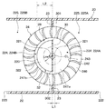
図1に示すように、送風ユニット1は、外気および内気を取り入れるための内外気導入部10、および内外気導入部10の空気流れ下流側に配置された送風機20を備えている。内外気導入部10は、外殻を構成する内外気ケース12を備えている。内外気ケース12の内側には、空気を導入する空気導入流路120が形成されている。空気導入流路120には、吸込仕切板121が設けられている。吸込仕切板121は、空気導入流路120を第1導入路122と第2導入路123とに仕切っている。第1導入路122および第2導入路123は、吸込仕切板121によって隔てられているので、温度または湿度等の性質の異なる空気が混ざり合うことなく流れることが可能となっている。
As shown in FIG. 1, the
第1導入路122および第2導入路123の空気流れ最上流側には、それぞれ外気導入口124、125、および内気導入口126、127が形成されている。外気導入口124、125は、外気を第1導入路122および第2導入路123に導入するための開口である。内気導入口126、127は、内気を第1導入路122および第2導入路123に導入するための開口である。
Outside
第1導入路122には、第1導入路122の外気導入口124および内気導入口126の開口面積を調整し、内気の導入量と外気の導入量との割合を変化させる第1内外気切替ドア14が設けられている。
In the first introduction path 122, a first inside/outside air switching mode in which the opening areas of the outside
また、第2導入路123には、第2導入路123の外気導入口125および内気導入口127の開口面積を調整し、内気の導入量と外気の導入量との割合を変化させる第2内外気切替ドア16が設けられている。
In addition, in the second introduction path 123, a second inside/outside for adjusting the opening area of the outside
例えば、第1導入路122に外気を導入し第2導入路123に内気を導入する内外気二層モード時には、図1に示すように、第1内外気切替ドア14が外気導入口124を開くとともに内気導入口126を閉じる位置に設定される。この際、第2内外気切替ドア16は、内気導入口127を開くとともに外気導入口125を閉じる位置に設定される。
For example, in the inside/outside air two-layer mode in which the outside air is introduced into the first introduction path 122 and the inside air is introduced into the second introduction path 123, the first inside/outside
図示しないが、第1導入路122および第2導入路123の双方に外気を導入する外気モード時には、第1内外気切替ドア14および第2内外気切替ドア16が外気導入口124、125を開くとともに内気導入口126、127を閉じる位置に設定される。
Although not shown, in the outside air mode in which the outside air is introduced into both the first introduction path 122 and the second introduction path 123, the first inside/outside
また、図示しないが、第1導入路122および第2導入路123の双方に内気を導入する内気モード時には、第1内外気切替ドア14および第2内外気切替ドア16が内気導入口126、127を開くとともに外気導入口124、125を閉じる位置に設定される。
Further, although not shown, in the inside air mode in which the inside air is introduced into both the first introduction path 122 and the second introduction path 123, the first inside/outside
本実施形態では、第1内外気切替ドア14および第2内外気切替ドア16の一例としてロータリドアを示したが、これに限定されない。第1内外気切替ドア14および第2内外気切替ドア16は、板ドア、スライドドア等で構成されていてもよい。
In the present embodiment, the rotary door is shown as an example of the first inside/outside
このように構成される内外気導入部10の空気流れ下流側には、送風機20が配置されている。送風機20は、第1流体としての外気と第2流体としての内気を送風可能に構成されている。
The
送風機20は、外殻を構成する送風ケース22、送風ケース22の内側に収容された遠心ファン24、遠心ファン24を駆動する電動モータ26、および隔壁28を含んで構成されている。
The
送風ケース22は、内外気導入部10から導入された空気を吸い込むための吸込口221、遠心ファン24から吹き出された空気を図示しない温度調整ユニットに吹き出す一対の吹出口222、223が形成されている。
The
送風ケース22の内側には、吸込口221を介して遠心ファン24の内側に吸い込んだ空気が流れる吸込空間224が形成されている。吸込空間224は、遠心ファン24のファン軸心CLを中心とする円柱状の空間である。なお、ファン軸心CLは、遠心ファン24の回転中心線である。
Inside the
吸込空間224は、隔壁28によって第1導入路122からの空気(すなわち、第1流体)が通る第1空間224Aと、第2導入路123からの空気(すなわち、第2流体)が通る第2空間224Bとに仕切られている。
The
また、送風ケース22には、遠心ファン24から吹き出された空気を吹出口222、223に導く吹出流路225が形成されている。この吹出流路225は、遠心ファン24のファン径方向DRの外側に形成されている。なお、ファン径方向DRは、ファン軸心CLに直交する方向を示している。
Further, the
図2に示すように、本実施形態の吹出流路225は、送風ケース22に形成された吹出仕切部23によって第1導入路122からの空気が通る第1吹出流路225Aと、第2導入路123からの空気が通る第2吹出流路225Bとに仕切られている。吹出仕切部23は、送風ケース22の側壁面から遠心ファン24に向かって突き出るリブで構成されている。
As shown in FIG. 2, the blowout flow passage 225 of the present embodiment includes a first blowout flow passage 225A through which air from the first introduction passage 122 passes by the
送風ケース22の内側には、遠心ファン24が収容されている。遠心ファン24は、ファン軸心CLを中心に回転することで、ファン軸心CLの一方側から吸い込んだ空気をファン径方向DRの外側に吹き出すファンである。
A
図1に示すように、遠心ファン24は、複数枚のブレード242、ファンシュラウド244、およびファンボス246を有している。本実施形態の遠心ファン24は、各ブレード242、ファンシュラウド244、およびファンボス246が樹脂による一体成形物として構成されている。なお、遠心ファン24は、樹脂に限らず金属材料で構成されていてもよい。
As shown in FIG. 1, the
本実施形態の遠心ファン24は、遠心ファン24の中でも静圧が高いといった特性を有するターボファンで構成されている。なお、遠心ファン24は、ターボファンに限らず、ラジアルファンやシロッコファンで構成されていてもよい。
The
図2に示すように、複数枚のブレード242は、ファン軸心CLを中心とする円柱状の吸込空間224の周りに周方向に一定の間隔をあけて配置されている。遠心ファン24は、各ブレード242がファン軸心CLの周りを回転することでファン軸心CLの一方側から空気が吸い込まれる。
As shown in FIG. 2, the plurality of
ファンシュラウド244は、円環状に形成されている。ファンシュラウド244は、各ブレード242のファン軸心CLの一方側に接続されている。各ブレード242は、ファンシュラウド244によって互いに連結されている。
The
ファンボス246は、円盤状に形成されている。ファンボス246は、各ブレード242のファン軸心CLの他方側に接続されている。ファンボス246は、ファン径方向DRの内側の部位がファン径方向DRの外側の部位に比べてファン軸心CLの一方側に突き出ている。ファンボス246は、ファン軸心CLを対称軸とする軸対称形状になっている。ファンボス246の略中央部分には、遠心ファン24を電動モータ26の出力軸262を連結するボス部246aが設けられている。
The
電動モータ26は、遠心ファン24を回転駆動させる電動機である。電動モータ26は、その一部が送風ケース22の内側に収容され、残りの部分が送風ケース22から外部に露出している。電動モータ26の出力軸262は、遠心ファン24に連結されている。電動モータ26の回転駆動力が出力軸262を介して遠心ファン24に伝達されることで、遠心ファン24がファン軸心CLの周りを回転する。
The
続いて、隔壁28は、遠心ファン24の空気吸込側に形成される吸込空間224に配置されている。隔壁28は、遠心ファン24に対して間隔をあけて配置されている。隔壁28は、回転しないように送風ケース22の内側壁面等に対して接着等で固定されている。
Subsequently, the
隔壁28は、吸込空間224を第1導入路122からの空気が通る第1空間224Aと、第2導入路123からの空気が通る第2空間224Bとに仕切るベース部30を備えている。
The
図1に示すように、ベース部30は、吸込空間224においてファン軸心CLに沿って延びている。ベース部30は、ファン軸心CLの一方側が内外気導入部10の吸込仕切板121に連なっている。ベース部30は、ファン軸心CLの他方側が遠心ファン24のファンボス246の略中央部分の手前まで延びている。
As shown in FIG. 1, the
また、ベース部30は、図2に示すように、ファン軸心CLから離れる方向に対して直線状に延びている。ベース部30は、各ブレード242と干渉しないように、ファン軸心CLから最も離れた外側の両端部301、302が各ブレード242の手前まで延びている。ベース部30には、ファン軸心CLの他方側に拡大部32が接続されている。
Further, as shown in FIG. 2, the
拡大部32は、ファンボス246の一部を覆うようにファン軸心CL側からブレード242に近づく方向に延びている。拡大部32は、ファンボス246と干渉しないようにファンボス246に対して所定の間隔をあけて配置されている。
The
拡大部32とファンボス246との間には、第1空間224A側に開口する第1空間側開口部331と第2空間224B側に開口する第2空間側開口部332を連通させる隙間流路33が形成されている。
Between the
ここで、車両用空調装置では、内外気二層モード時に内気よりも湿度が低い外気を車両の窓ガラスの内側に吹き出しつつ内気を車室内で循環させることで、窓曇りの防止と空調負荷の低減とを両立させることが可能となっている。 Here, in the vehicle air conditioner, the outside air having a lower humidity than the inside air in the inside/outside air two-layer mode is blown into the inside of the window glass of the vehicle while the inside air is circulated in the vehicle compartment, thereby preventing the fogging of the window and the air conditioning load. It is possible to achieve both reduction and reduction.
ところが、送風機20には、拡大部32とファンボス246との間に隙間流路33が設けられているので、第2流体である内気が隙間流路33を介して第1空間224A側に流れ込んでしまう虞がある。第2流体である内気が隙間流路33を介して第1空間224A側に流れ込むと、車両の窓ガラスに向けて湿度の高い空気が供給されることで、窓曇りが生じ易くなってしまう。窓曇りが生ずるとユーザによる車両の運転操作に支障が生ずるため回避する必要がある。
However, since the
上記課題を解決するために、本発明者らは送風機20のファン特性等について鋭意検討した。この結果、遠心ファン24の吸込空間224では、図3に示すように、各ブレード242の前縁部243側の方がファン軸心CL側に比べて圧力が低くなる傾向があることを見出した。各ブレード242付近で圧力が低下する理由は、以下の通りである。すなわち、遠心ファン24は、各ブレード242の間の空気に遠心力を付与してファン径方向DRの外側へ吹き出す構造となっている。このため、各ブレード242の前縁部243から空気を吸い込んでいくことになるので、各ブレード242の前縁部243の方がファン軸心CLよりも圧力が低くなる。
In order to solve the above-mentioned subject, the present inventors diligently studied fan characteristics and the like of the
本実施形態では、上述の知見に基づいて、隙間流路33の第2空間側開口部332側の圧力が第1空間側開口部331側の圧力よりも低くなるように、拡大部32を、吸込空間224のうち第2空間224B側に偏って存在する形状としている。
In the present embodiment, based on the above-mentioned findings, the
本実施形態の拡大部32は、ファン軸心CLからブレード242の前縁部243に相対する外縁部320までの距離が所定の基準距離Lrefよりも長くなる延在部位を有している。そして、拡大部32、前述の延在部位が吸込空間224のうち第2空間224B側に偏って存在する形状となっている。本実施形態では、基準距離Lrefをファン軸心CLからブレード242の前縁部243までの距離の半分の長さに設定している。なお、基準距離Lrefについては、送風機20の種類等に応じて適宜変更することができる。例えば、例えば、後述する筒状部321の半径の長さを基準距離Lrefに設定することができる。
The
具体的には、図4および図5に示すように、拡大部32は、ファンボス246のボス部246aを覆う筒状部321、および筒状部321からファン径方向DRの外側に向かって突き出るフランジ部322を有している。
Specifically, as shown in FIGS. 4 and 5, the
筒状部321は、ファンボス246のボス部246a全体を覆う有底の円筒形状となっている。筒状部321は、ファンボス246のボス部246aと干渉しないように、ファン軸心CLの一方側に突き出ている。
The
本実施形態のフランジ部322は、ファン軸心CLの延在方向の正面形状が半円形状となっている。フランジ部322は、各ブレード242と干渉しないように、ファン軸心CLから離れた外縁部320が各ブレード242の手前まで延びている。フランジ部322は、ファン軸心CLから外縁部320までの距離が前述の基準距離Lrefよりも長くなるように、筒状部321からファン径方向DRの外側に向かって突き出ている。本実施形態では、拡大部32におけるフランジ部322が前述の延在部位を構成している。
The
このように構成される拡大部32は、図1および図2に示すように、第1空間224A側に筒状部321の一部が突き出るとともに第2空間224B側に筒状部321の残りとフランジ部322が突き出るように吸込空間224に配置される。すなわち、本実施形態の拡大部32は、第1ファンボス部247aおよび第2ファンボス部247bの双方を覆うように構成されている。そして、本実施形態の拡大部32は、第2空間224B側におけるファン軸心CLから外縁部320までの距離L2が、第1空間224A側におけるファン軸心CLから外縁部320までの距離L1よりも長くなっている。
As shown in FIGS. 1 and 2, in the
換言すれば、拡大部32は、第2ファンボス部247bを覆う部位が、第1ファンボス部247aを覆う部位の面積に比べて、ファン軸心CLから外縁部320までの距離が長くなっている。
In other words, in the
また、本実施形態の拡大部32は、図5に示すように、第2ファンボス部247bを覆う部位の面積S2が、第1ファンボス部247aを覆う部位の面積S1に比べて大きくなっている。なお、図5では、便宜上、拡大部32のうち第2ファンボス部247bを覆う部位に縦線ハッチングを付し、拡大部32のうち第1ファンボス部247aを覆う部位に横線ハッチングを付している。
Further, in the
次に、本実施形態の送風ユニット1の内外気二層モード時の作動について図6および図7を参照して説明する。送風ユニット1は、図6に示すように、内外気二層モード時に、第1内外気切替ドア14が外気導入口124を開くとともに内気導入口126を閉じる位置に設定される。この状態で電動モータ26によって遠心ファン24が回転駆動されると、図6の矢印Ff1に示すように第1導入路122に外気が導入され、図6の矢印Fr1に示すように第2導入路123に内気が導入される。
Next, the operation of the
第1導入路122に導入された外気は、図6の矢印Ff2に示すように、吸込空間224のうち第1空間224Aから遠心ファン24に吸い込まれた後、ファン径方向DRの外側の第1吹出流路225Aに吹き出される。そして、第1吹出流路225Aに吹き出された外気は、温度調整ユニットの内部で所望の温度に調整された後、車両の窓ガラスの内側に向けて吹き出される。
The outside air introduced into the first introduction path 122 is sucked into the
一方、第2導入路123に導入された内気は、図6の矢印Fr2に示すように、吸込空間224のうち第2空間224Bから遠心ファン24に吸い込まれた後、ファン径方向DRの外側の第2吹出流路225Bに吹き出される。第1吹出流路225Aに吹き出された内気は、温度調整ユニットの内部で所望の温度に調整された後、車室内の乗員に向けて吹き出される。
On the other hand, the inside air introduced into the second introduction path 123 is sucked into the
ここで、本実施形態の送風機20は、隙間流路33の第2空間側開口部332側の圧力が第1空間側開口部331側の圧力に比べて低くなるように、拡大部32が第2空間224B側に偏って存在する構成となっている。
Here, in the
このため、拡大部32とファンボス246との間に形成される隙間流路33では、図7の矢印Flに示すように、第2空間224Bに向かう外気の流れが支配的となる。これにより、内気が隙間流路33を介して第1空間224Aに流れ難くなる。
Therefore, in the
以上説明した本実施形態によれば、遠心ファン24の吸込空間224が隔壁28によって外気が流れる第1空間224Aおよび内気が流れる第2空間224Bに仕切られた送風機20において、第1空間224Aに対する内気の流れ込みを抑制することができる。この結果、車両の窓ガラスの内側に向けて低湿度の空気(すなわち、外気)を供給することができる。
According to the present embodiment described above, in the
また、本実施形態の送風機20は、拡大部32にて第1ファンボス部247aおよび第2ファンボス部247bの双方が覆われる構成になっている。これによると、ファンボス246と拡大部32との間に形成される隙間流路33を充分に確保することができ、隙間流路33を介した外気と内気との混合を抑制することができる。この際、拡大部32によって第2ファンボス部247bを覆う面積が第1ファンボス部247aを覆う面積に比べて大きくなっているので、内気が隙間流路33を介して第1空間224Aに流れ込むことを抑制することができる。
Further, the
さらに、本実施形態の拡大部32は、第2ファンボス部247bを覆う部位が、第1ファンボス部247aを覆う部位に比べて、ファン軸心CLからブレード242の前縁部243に相対する外縁部320までの距離が長くなっている。これによると、隙間流路33のうち、第2空間側開口部332が第1空間側開口部331よりもブレード242に近づくので、第2空間側開口部332の圧力を第1空間側開口部331の圧力よりも低くすることができる。
Further, in the
(第2実施形態)
本実施形態について、図8、図9を参照して説明する。本実施形態の送風機20は、拡大部32の形状が第1実施形態に対して異なっている。本実施形態では、第1実施形態と異なる部分について主に説明し、同様の部分についての説明を省略する。
(Second embodiment)
This embodiment will be described with reference to FIGS. 8 and 9. The
図8および図9に示すように、本実施形態の送風機20の拡大部32は、第1ファンボス部247aおよび第2ファンボス部247bのうち第2ファンボス部247bだけを覆うように構成されている。
As shown in FIGS. 8 and 9, the
具体的には、本実施形態の拡大部32は、筒状部321がファンボス246のボス部246aの半分を覆う有底の半円筒形状となっている。そして、拡大部32は、ファンボス部のうち第2ファンボス部247bだけが覆われるように、第2空間224B側にだけ突き出るように吸込空間224に配置される。
Specifically, the
本実施形態の拡大部32は、第1空間224A側に突き出ていないので、第1空間224A側におけるファン軸心CLから外縁部320までの距離がゼロになる。このため、拡大部32は、第2空間224B側におけるファン軸心CLから外縁部320までの距離L2が、第1空間224A側におけるファン軸心CLから外縁部320までの距離よりも長くなる。
Since the
また、本実施形態の拡大部32は、第1空間224A側に突き出ていないので、第1ファンボス部247aを覆う部位の面積がゼロになる。このため、拡大部32は、第2ファンボス部247bを覆う部位の面積S2が、第1ファンボス部247aを覆う部位の面積に比べて大きくなっている。
Moreover, since the
その他の構成は、第1実施形態と同様である。本実施形態の送風機20は、第1実施形態と共通の構成から奏される作用効果を第1実施形態と同様に得ることができる。特に、本実施形態の送風機20は、拡大部32が第2ファンボス部247bだけを覆うように構成されている。
Other configurations are similar to those of the first embodiment. The
これによると、ファンボス246と拡大部32との間に形成される隙間流路33のうち、第2空間側開口部332における圧力と第1空間側開口部331における圧力との圧力差を充分に確保することができる。この結果、外気が第2空間224B側に流れ易くなるので、第1空間224Aに対する内気の流れ込みを充分に抑制することができる。
According to this, in the
(第3実施形態)
本実施形態について、図10、図11を参照して説明する。本実施形態の送風機20は、拡大部32の形状が第1実施形態に対して異なっている。本実施形態では、第1実施形態と異なる部分について主に説明し、同様の部分についての説明を省略する。
(Third Embodiment)
This embodiment will be described with reference to FIGS. 10 and 11. The
図10および図11に示すように、本実施形態の拡大部32は、ファン軸心CLの延在方向の正面形状が半円形状と半楕円形状とを組み合わせた形状となっている。拡大部32における半楕円形状となる部位の長軸半径は、半円形状となる部位の半径よりも小さくなっている。
As shown in FIGS. 10 and 11, the
本実施形態の拡大部32は、半円形状となる部位が第2ファンボス部247bを覆うとともに、半楕円形状となる部位が第1ファンボス部247aを覆うように吸込空間224に配置される。
The
ここで、本実施形態の拡大部32は、第2空間224B側におけるファン軸心CLから外縁部320までの距離L2が、第1空間224A側におけるファン軸心CLから外縁部320までの距離L1よりも長くなっている。また、本実施形態の拡大部32は、第2ファンボス部247bを覆う部位の面積S2が、第1ファンボス部247aを覆う部位の面積S1に比べて大きくなっている。
Here, in the expanded
その他の構成は、第1実施形態と同様である。本実施形態の送風機20は、第1実施形態と同様に、隙間流路33の第2空間側開口部332側の圧力が第1空間側開口部331側の圧力に比べて低くなるように、拡大部32が第2空間224B側に偏って存在する構成となっている。このため、本実施形態の送風機20は、第1空間224Aに対する内気の流れ込みを抑制することができる。
Other configurations are similar to those of the first embodiment. In the
(第4実施形態)
本実施形態について、図12、図13を参照して説明する。本実施形態の送風機20は、拡大部32の形状が第1実施形態に対して異なっている。本実施形態では、第1実施形態と異なる部分について主に説明し、同様の部分についての説明を省略する。
(Fourth Embodiment)
The present embodiment will be described with reference to FIGS. 12 and 13. The
図12および図13に示すように、本実施形態の送風機20の拡大部32は、ファン軸心CLの延在方向の正面形状が半円形状と扇形状とを組み合わせた形状となっている。拡大部32における扇形状となる部位の半径は、半円形状となる部位の半径と同等の大きさになっている。
As shown in FIGS. 12 and 13, the
本実施形態の拡大部32は、半円形状となる部位が第2ファンボス部247bを覆うとともに、扇形状となる部位が第1ファンボス部247aを覆うように吸込空間224に配置される。
The
ここで、本実施形態の拡大部32は、第2空間224B側におけるファン軸心CLから外縁部320までの距離L2と、第1空間224A側におけるファン軸心CLから外縁部320までの距離L1とが同等となる。
Here, in the
一方、拡大部32のうちファン軸心CLから外縁部320までの距離が所定の基準距離Lrefよりも長くなる延在部位は、吸込空間224のうち第2空間224B側に偏って存在している。そして、本実施形態の拡大部32は、第2ファンボス部247bを覆う部位の面積S2が、第1ファンボス部247aを覆う部位の面積S1に比べて大きくなっている。
On the other hand, the extended portion of the
これにより、本実施形態の送風機20は、隙間流路33の第2空間側開口部332側の圧力と第1空間側開口部331側の圧力とが同等となる部分を有するものの、全体として第2空間側開口部332側の圧力が第1空間側開口部331側の圧力よりも低くなる。すなわち、本実施形態の送風機20は、隙間流路33の第2空間側開口部332側の圧力が第1空間側開口部331側の圧力に比べて低くなるように、拡大部32が第2空間224B側に偏って存在する構成となっている。
As a result, the
その他の構成は、第1実施形態と同様である。本実施形態の送風機20は、第1実施形態と同様に、吸込空間224のうち第1空間224Aに対する内気の流れ込みを抑制することができる。
Other configurations are similar to those of the first embodiment. The
(第5実施形態)
本実施形態について、図14、図15を参照して説明する。本実施形態の送風機20は、拡大部32の形状が第1実施形態に対して異なっている。本実施形態では、第1実施形態と異なる部分について主に説明し、同様の部分についての説明を省略する。
(Fifth Embodiment)
This embodiment will be described with reference to FIGS. 14 and 15. The
図14および図15に示すように、本実施形態の拡大部32は、ファン軸心CLにおける正面形状が半円形状に対してファン径方向DRの内側に窪んだ切欠部323が設けられた形状となっている。
As shown in FIGS. 14 and 15, the
具体的には、本実施形態の拡大部32は、フランジ部322に対して扇状の切欠部323が形成されている。この切欠部323は、外縁部320側から筒状部321まで延びている。そして、本実施形態の拡大部32は、切欠部323が設けられたフランジ部322で第2ファンボス部247bが覆われるように吸込空間224に配置される。
Specifically, in the
ここで、本実施形態の拡大部32は、第2空間224B側における切欠部323が設けられた部位でのファン軸心CLからの距離Ls2と、第1空間224A側におけるファン軸心CLから外縁部320までの距離L1とが同等となる。
Here, the
一方、拡大部32のうちファン軸心CLから外縁部320までの距離が所定の基準距離Lrefよりも長くなる延在部位は、吸込空間224のうち第2空間224B側に偏って存在している。そして、本実施形態の拡大部32は、第2ファンボス部247bを覆う部位の面積S2が、第1ファンボス部247aを覆う部位の面積S1に比べて大きくなっている。
On the other hand, the extended portion of the
これにより、本実施形態の送風機20は、隙間流路33の第2空間側開口部332側の圧力と第1空間側開口部331側の圧力とが同等となる部分を有するものの、全体として第2空間側開口部332側の圧力が第1空間側開口部331側の圧力よりも低くなる。すなわち、本実施形態の送風機20は、隙間流路33の第2空間側開口部332側の圧力が第1空間側開口部331側の圧力に比べて低くなるように、拡大部32が第2空間224B側に偏って存在する構成となっている。
As a result, the
その他の構成は、第1実施形態と同様である。本実施形態の送風機20は、第1実施形態と同様に、吸込空間224のうち第1空間224Aに対する内気の流れ込みを抑制することができる。
Other configurations are similar to those of the first embodiment. The
(第6実施形態)
本実施形態について、図16を参照して説明する。本実施形態の送風機20は、ベース部30の形状が第1実施形態に対して異なっている。本実施形態では、第1実施形態と異なる部分について主に説明し、同様の部分についての説明を省略する。
(Sixth Embodiment)
This embodiment will be described with reference to FIG. The
図16に示すように、本実施形態のベース部30は、ブレード242に相対する両端部301、302が、ファン軸心CL側の部位に比べて第2吹出流路225B側に位置付けられている。すなわち、ベース部30は、ブレード242に相対する両端部301、302が第2吹出流路225B側に位置するように折れ曲がった形状となっている。
As shown in FIG. 16, in the
その他の構成は第1実施形態と同様である。本実施形態の送風機20は、第1実施形態と共通の構成から奏される作用効果を第1実施形態と同様に得ることができる。特に、本実施形態では、ベース部30のうちブレード242に相対する両端部301、302が、ファン軸心CL側の部位に比べて第2吹出流路225B側に位置付けられている。これによると、第1空間224Aを流れる空気がベース部30と各ブレード242との隙間を介して第2空間224B側に流れ易くなるので、第2空間224B側への外気の流れ込みを抑制することができる。
Other configurations are similar to those of the first embodiment. The
(他の実施形態)
以上、本発明の代表的な実施形態について説明したが、本発明は、上述の実施形態に限定されることなく、例えば、以下のように種々変形可能である。
(Other embodiments)
The representative embodiment of the present invention has been described above, but the present invention is not limited to the above-described embodiment, and various modifications can be made as follows, for example.
上述の各実施形態では、別体で構成された内外気導入部10の吸込仕切板121と送風機20の隔壁28とを接続する例について説明したが、これに限定されない。送風機20は、内外気導入部10の吸込仕切板121と送風機20の隔壁28とが一体成形物として構成されていてもよい。
In each of the above-described embodiments, an example in which the
上述の第1〜第5実施形態では、ベース部30がファン軸心CLから離れる方向に対して直線状に延びている例について説明したが、これに限定されない。ベース部30は、例えば、L字状に曲折した形状となっていてもよい。
In the above-described first to fifth embodiments, an example has been described in which the
上述の各実施形態では、車両用空調装置として、送風機20の空気流れ下流側に温度調整ユニットが配置される例について説明したが、これに限定されない。車両用空調装置は、例えば、送風機20の空気流れ上流側に温度調整ユニットが配置された構成になっていてもよい。また、車両用空調装置は、例えば、送風機20の空気流れ上流側に冷却用熱交換器が配置され、送風機20の空気流れ下流側に加熱用熱交換器が配置される構成になっていてもよい。
In each of the above-described embodiments, an example in which the temperature adjustment unit is arranged on the air flow downstream side of the
上述の各実施形態では、本発明の送風機20を車両用空調装置に適用する例について説明したが、これに限定されない。本発明の送風機20は、第2流体が第1流体に混入することを回避する必要がある装置(例えば、加湿器)に対して広く適用可能である。
In each of the above-described embodiments, an example in which the
上述の実施形態において、実施形態を構成する要素は、特に必須であると明示した場合および原理的に明らかに必須であると考えられる場合等を除き、必ずしも必須のものではないことは言うまでもない。 It goes without saying that, in the above-described embodiments, the elements constituting the embodiments are not necessarily essential except when explicitly stated as being essential and when it is apparently essential in principle.
上述の実施形態において、実施形態の構成要素の個数、数値、量、範囲等の数値が言及されている場合、特に必須であると明示した場合および原理的に明らかに特定の数に限定される場合等を除き、その特定の数に限定されない。 In the above-described embodiment, when numerical values such as the number, numerical value, amount, range, etc. of the constituent elements of the embodiment are referred to, when explicitly stated to be essential, and in principle limited to a specific number It is not limited to the specific number except for cases.
上述の実施形態において、構成要素等の形状、位置関係等に言及するときは、特に明示した場合および原理的に特定の形状、位置関係等に限定される場合等を除き、その形状、位置関係等に限定されない。 In the above-described embodiments, when referring to the shapes and positional relationships of constituent elements and the like, the shapes and positional relationships are excluded unless otherwise specified and in principle limited to specific shapes and positional relationships. It is not limited to the above.
(まとめ)
上述の実施形態の一部または全部で示された第1の観点によれば、送風機は、拡大部とファンボスとの間に、第1空間側に開口する第1空間側開口部と第2空間側に開口する第2空間側開口部を連通させる隙間流路が形成されている。そして、隔壁は、第2空間側開口部側の圧力が第1空間側開口部側の圧力に比べて低くなるように、拡大部が第2空間側に偏って存在する構成となっている。
(Summary)
According to the first aspect described in part or all of the above-described embodiment, the blower includes the first space-side opening and the second space-side opening that are open to the first space between the enlarged portion and the fan boss. A gap flow path is formed that communicates the second space side opening that opens to the space side. Further, the partition wall is configured such that the enlarged portion is biased toward the second space side so that the pressure on the second space side opening side is lower than the pressure on the first space side opening side.
上述の実施形態の一部または全部で示された第2の観点によれば、送風機の拡大部は、ファン軸心からブレードの前縁部に相対する外縁部までの距離が所定の基準距離よりも長くなる延在部位を有する。そして、拡大部は、延在部位が吸込空間のうち第2空間側に偏って存在する構成となっている。 According to the second aspect shown in part or all of the above-described embodiment, in the enlarged portion of the blower, the distance from the fan axis to the outer edge portion facing the front edge portion of the blade is smaller than the predetermined reference distance. Also has a lengthened extension. Then, the enlarged portion has a configuration in which the extending portion is biased toward the second space side of the suction space.
第3の観点によれば、送風機の拡大部は、第1空間側に比べて第2空間側の方がファンボスを覆う部位の面積が大きくなっている。これによると、第1空間側に比べて第2空間側の方がファンボスと拡大部との間に形成される隙間流路を確保することができるので、第2流体が隙間流路を介して第1空間に流れ込むことを充分に抑制することができる。 According to the third aspect, in the expanded portion of the blower, the area of the portion that covers the fan boss is larger on the second space side than on the first space side. According to this, the gap space formed between the fan boss and the enlarged portion can be secured on the second space side as compared to the first space side, so that the second fluid passes through the gap passage. Flow into the first space can be sufficiently suppressed.
第4の観点によれば、送風機の拡大部は、第1ファンボス部および第2ファンボス部の双方を覆うように構成され、第2ファンボス部を覆う部位の面積が、第1ファンボス部を覆う部位の面積に比べて大きくなっている。第1ファンボス部は、ファンボスのうち第1空間側に位置する部位である。また、第2ファンボス部は、ファンボスのうち第2空間側に位置する部位である。 According to a fourth aspect, the enlarged portion of the blower is configured to cover both the first fan boss portion and the second fan boss portion, and the area of the portion covering the second fan boss portion is the first fan boss portion. It is larger than the area of the part that covers the part. The first fan boss portion is a portion of the fan boss located on the first space side. The second fan boss portion is a portion of the fan boss located on the second space side.
第5の観点によれば、送風機は、拡大部のうち第2ファンボス部を覆う部位は、拡大部のうち第1ファンボス部を覆う部位に比べて、ファン軸心からブレードの前縁部に相対する外縁部までの距離が長くなっている。これによると、ファンボスと拡大部との間に形成される隙間流路のうち、第2空間側に開口する開口部が第1空間側に開口する開口部よりもブレードに近づくので、第2空間側の開口部の圧力を第1空間側の開口部の圧力よりも低くすることができる。 According to a fifth aspect, in the blower, the portion of the enlarged portion that covers the second fan boss portion is located farther from the fan shaft center than the portion of the enlarged portion that covers the first fan boss portion. The distance to the outer edge facing is longer. According to this, in the clearance channel formed between the fan boss and the enlarged portion, the opening opening to the second space side is closer to the blade than the opening opening to the first space side. The pressure in the opening on the space side can be made lower than the pressure in the opening on the first space side.
第6の観点によれば、送風機の拡大部は、第1ファンボス部および第2ファンボス部のうち第2ファンボス部だけを覆うように構成されている。これによると、ファンボスと拡大部との間に形成される隙間流路のうち、第2空間側の開口部における圧力と第1空間側の開口部における圧力との圧力差を充分に確保することができる。この結果、第1流体が第2空間側に流れ易くなるので、第1空間に対する第2流体の流れ込みを充分に抑制することができる。 According to the sixth aspect, the enlarged portion of the blower is configured to cover only the second fan boss portion of the first fan boss portion and the second fan boss portion. According to this, in the gap flow path formed between the fan boss and the enlarged portion, a sufficient pressure difference between the pressure at the opening on the second space side and the pressure at the opening on the first space side is secured. be able to. As a result, the first fluid easily flows toward the second space, so that the inflow of the second fluid into the first space can be sufficiently suppressed.
第7の観点によれば、送風機は、車室外から外気を導入しつつ、車室内から導入された内気を前記車室内で循環させる内外気二層モードを実施可能な車両用空調装置に適用される。そして、前述の第1流体は外気である。また、前述の第2流体は内気である。これによれば、送風機の内部において、外気が通る空間に対して内気の流れ込みを抑制することができるので、例えば、車両用の窓ガラスの内側に向けて低湿度の空気(すなわち、外気)を供給することができる。 According to a seventh aspect, the blower is applied to a vehicle air conditioner capable of performing an inside/outside air two-layer mode in which the outside air is introduced from the outside of the vehicle compartment and the inside air introduced from the vehicle compartment is circulated in the vehicle compartment. It And the above-mentioned first fluid is the outside air. Further, the above-mentioned second fluid is the inside air. According to this, since it is possible to suppress the inflow of the inside air into the space through which the outside air passes inside the blower, for example, air with low humidity is directed toward the inside of the window glass for the vehicle (that is, outside air). Can be supplied.
224 吸込空間
224A 第1空間
224B 第2空間
24 遠心ファン
28 隔壁
30 ベース部
32 拡大部
33 隙間流路
331 第1空間側開口部
332 第2空間側開口部
224 Suction space 224A 1st space 224B
Claims (7)
ファン軸心(CL)を中心に回転することで前記ファン軸心の一方側から吸い込んだ前記第1流体および前記第2流体を前記ファン軸心から遠ざかる方向に吹き出す遠心ファン(24)と、
前記遠心ファンに対して間隔をあけて配置され、前記遠心ファンの空気吸込側に形成される吸込空間(224)に設けられた隔壁(28)と、を備え、
前記遠心ファンは、
前記吸込空間の周りに間隔をあけて配置され、前記ファン軸心の周りを回転することで前記ファン軸心の一方側から空気を吸い込む複数枚のブレード(242)と、
前記複数枚のブレードのうち前記ファン軸心の他方側を連結するファンボス(246)と、を有し、
前記隔壁は、
前記吸込空間において前記ファン軸心に沿って延びるとともに前記吸込空間を少なくとも前記第1流体が通る第1空間(224A)と前記第2流体が通る第2空間(224B)に仕切るベース部(30)と、
前記ベース部における前記ファン軸心の他方側に接続され、前記ファン軸心側から前記ブレードに近づく方向に延びて前記ファンボスの一部を覆う拡大部(32)と、を有し、
前記ベース部は、前記ファン軸心から最も離れた外側の両端部(301、302)が前記複数枚のブレードの手前に位置するように前記ファン軸心から離れる方向に延びており、
前記拡大部と前記ファンボスとの間には、前記第1空間側に開口する第1空間側開口部(331)と前記第2空間側に開口する第2空間側開口部(332)を連通させる隙間流路(33)が形成されており、
前記拡大部は、前記第2空間側開口部側の圧力が前記第1空間側開口部側の圧力よりも低くなるように、前記吸込空間のうち前記第2空間側に偏って存在している送風機。 A blower capable of blowing the first fluid and the second fluid,
A centrifugal fan (24) that blows out the first fluid and the second fluid sucked from one side of the fan shaft center in a direction away from the fan shaft center by rotating around the fan shaft center (CL);
A partition wall (28) provided at a space with respect to the centrifugal fan and provided in a suction space (224) formed on the air suction side of the centrifugal fan,
The centrifugal fan is
A plurality of blades (242) arranged at intervals around the suction space and sucking air from one side of the fan axis by rotating around the fan axis;
A fan boss (246) connecting the other side of the fan axis of the plurality of blades,
The partition wall is
A base portion (30) that extends along the fan axis in the suction space and partitions the suction space into at least a first space (224A) through which the first fluid passes and a second space (224B) through which the second fluid passes. When,
An enlarged portion (32) connected to the other side of the fan shaft center in the base portion, extending in a direction approaching the blade from the fan shaft center side, and covering a part of the fan boss;
The base portion extends in a direction away from the fan axis so that both outermost ends (301, 302) farthest from the fan axis are located in front of the plurality of blades.
A first space side opening (331) opening to the first space side and a second space side opening (332) opening to the second space side are communicated between the enlarged portion and the fan boss. A gap flow path (33) is formed,
The enlarged portion is biased toward the second space side of the suction space so that the pressure on the second space side opening side is lower than the pressure on the first space side opening side. Blower.
ファン軸心(CL)を中心に回転することで前記ファン軸心の一方側から吸い込んだ前記第1流体および前記第2流体を前記ファン軸心から遠ざかる方向に吹き出す遠心ファン(24)と、
前記遠心ファンに対して間隔をあけて配置され、前記遠心ファンの空気吸込側に形成される吸込空間(224)に設けられた隔壁(28)と、を備え、
前記遠心ファンは、
前記吸込空間の周りに間隔をあけて配置され、前記ファン軸心の周りを回転することで前記ファン軸心の一方側から空気を吸い込む複数枚のブレード(242)と、
前記複数枚のブレードのうち前記ファン軸心の他方側を連結するファンボス(246)と、を有し、
前記隔壁は、
前記吸込空間において前記ファン軸心に沿って延びるとともに前記吸込空間を少なくとも前記第1流体が通る第1空間(224A)と前記第2流体が通る第2空間(224B)に仕切るベース部(30)と、
前記ベース部における前記ファン軸心の他方側に接続され、前記ファン軸心側から前記ブレードに近づく方向に延びて前記ファンボスの一部を覆う拡大部(32)と、を有し、
前記ベース部は、前記ファン軸心から最も離れた外側の両端部(301、302)が前記複数枚のブレードの手前に位置するように前記ファン軸心から離れる方向に延びており、
前記拡大部は、前記ファン軸心から前記ブレードの前縁部(243)に相対する外縁部(320)までの距離が所定の基準距離よりも長くなる延在部位(322)を有し、前記延在部位が前記吸込空間のうち前記第2空間側に偏って存在している送風機。 A blower capable of blowing the first fluid and the second fluid,
A centrifugal fan (24) that blows out the first fluid and the second fluid sucked from one side of the fan shaft center in a direction away from the fan shaft center by rotating around the fan shaft center (CL);
A partition wall (28) provided at a space with respect to the centrifugal fan and provided in a suction space (224) formed on the air suction side of the centrifugal fan,
The centrifugal fan is
A plurality of blades (242) arranged at intervals around the suction space and sucking air from one side of the fan axis by rotating around the fan axis;
A fan boss (246) connecting the other side of the fan axis of the plurality of blades,
The partition wall is
A base portion (30) that extends along the fan axis in the suction space and partitions the suction space into at least a first space (224A) through which the first fluid passes and a second space (224B) through which the second fluid passes. When,
An enlarged portion (32) connected to the other side of the fan shaft center in the base portion, extending in a direction approaching the blade from the fan shaft center side, and covering a part of the fan boss;
The base portion extends in a direction away from the fan axis so that both outermost ends (301, 302) farthest from the fan axis are located in front of the plurality of blades.
The enlarged portion has an extending portion (322) in which a distance from the fan axis to an outer edge portion (320) facing the front edge portion (243) of the blade is longer than a predetermined reference distance, and An air blower in which an extending portion is biased toward the second space side of the suction space.
前記拡大部は、前記第1ファンボス部および前記第2ファンボス部の双方を覆うように構成され、前記第2ファンボス部を覆う部位の面積が、前記第1ファンボス部を覆う部位の面積に比べて大きくなっている請求項1ないし3のいずれか1つに記載の送風機。 Of the fan bosses, a portion located on the side of the first space is a first fan boss portion (247a) and a portion located on the side of the second space is a second fan boss portion (247b),
The enlarged portion is configured to cover both the first fan boss portion and the second fan boss portion, and the area of the portion that covers the second fan boss portion is equal to the area of the portion that covers the first fan boss portion. The blower according to any one of claims 1 to 3, which is larger than the area.
前記拡大部は、前記第1ファンボス部および前記第2ファンボス部のうち前記第2ファンボス部だけを覆うように構成されている請求項1ないし3のいずれか1つに記載の送風機。 Of the fan bosses, a portion located on the side of the first space is a first fan boss portion (247a) and a portion located on the side of the second space is a second fan boss portion (247b),
The blower according to claim 1, wherein the enlarged portion is configured to cover only the second fan boss portion of the first fan boss portion and the second fan boss portion.
前記第1流体は、前記外気であり、
前記第2流体は、前記内気である請求項1ないし6のいずれか1つに記載の送風機。 While introducing the outside air from the outside of the vehicle compartment, the inside air introduced from the inside of the vehicle compartment is applied to a vehicle air conditioner capable of performing an inside/outside air two-layer mode in which the inside air is circulated in the vehicle compartment,
The first fluid is the outside air,
The blower according to any one of claims 1 to 6, wherein the second fluid is the inside air.
Priority Applications (5)
| Application Number | Priority Date | Filing Date | Title |
|---|---|---|---|
| JP2017156251A JP6747402B2 (en) | 2017-08-11 | 2017-08-11 | Blower |
| PCT/JP2018/026368 WO2019031151A1 (en) | 2017-08-11 | 2018-07-12 | Blower |
| CN201880050704.6A CN111032384B (en) | 2017-08-11 | 2018-07-12 | Air blower |
| DE112018004126.3T DE112018004126T5 (en) | 2017-08-11 | 2018-07-12 | fan |
| US16/783,735 US11274670B2 (en) | 2017-08-11 | 2020-02-06 | Blower |
Applications Claiming Priority (1)
| Application Number | Priority Date | Filing Date | Title |
|---|---|---|---|
| JP2017156251A JP6747402B2 (en) | 2017-08-11 | 2017-08-11 | Blower |
Publications (3)
| Publication Number | Publication Date |
|---|---|
| JP2019034612A JP2019034612A (en) | 2019-03-07 |
| JP2019034612A5 JP2019034612A5 (en) | 2019-07-25 |
| JP6747402B2 true JP6747402B2 (en) | 2020-08-26 |
Family
ID=65272119
Family Applications (1)
| Application Number | Title | Priority Date | Filing Date |
|---|---|---|---|
| JP2017156251A Active JP6747402B2 (en) | 2017-08-11 | 2017-08-11 | Blower |
Country Status (5)
| Country | Link |
|---|---|
| US (1) | US11274670B2 (en) |
| JP (1) | JP6747402B2 (en) |
| CN (1) | CN111032384B (en) |
| DE (1) | DE112018004126T5 (en) |
| WO (1) | WO2019031151A1 (en) |
Families Citing this family (7)
| Publication number | Priority date | Publication date | Assignee | Title |
|---|---|---|---|---|
| JP6747469B2 (en) * | 2017-07-25 | 2020-08-26 | 株式会社デンソー | Vehicle air conditioning unit |
| JP6958221B2 (en) * | 2017-10-20 | 2021-11-02 | 株式会社デンソー | Vehicle air conditioner |
| JP2021000852A (en) * | 2019-06-19 | 2021-01-07 | 株式会社デンソー | Air conditioning unit |
| CN113357204B (en) | 2020-03-04 | 2023-11-17 | Lg电子株式会社 | Blower fan |
| US11473593B2 (en) * | 2020-03-04 | 2022-10-18 | Lg Electronics Inc. | Blower comprising a fan installed in an inner space of a lower body having a first and second upper body positioned above and a space formed between the bodies wherein the bodies have a first and second openings formed through respective boundary surfaces which are opened and closed by a door assembly |
| KR20210129307A (en) * | 2020-04-17 | 2021-10-28 | 현대자동차주식회사 | Air conditioning system for vehicle |
| JP7514127B2 (en) | 2020-07-10 | 2024-07-10 | マーレ インターナショナル ゲゼルシャフト ミット ベシュレンクテル ハフツング | Air conditioning equipment |
Family Cites Families (14)
| Publication number | Priority date | Publication date | Assignee | Title |
|---|---|---|---|---|
| US4252181A (en) * | 1977-03-15 | 1981-02-24 | Johannes Kirchmeier | Heat recovering fan |
| JPS61263822A (en) * | 1985-05-17 | 1986-11-21 | Nippon Denso Co Ltd | Air conditioner for automobile |
| FR2788086B1 (en) * | 1998-12-30 | 2001-02-09 | Valeo Climatisation | HEATING, VENTILATION AND / OR AIR CONDITIONING DEVICE COMPRISING A SUCTION PULSE |
| JP3843928B2 (en) * | 2002-10-15 | 2006-11-08 | 株式会社デンソー | Centrifugal blower |
| WO2004055380A1 (en) * | 2002-12-16 | 2004-07-01 | Daikin Industries, Ltd. | Centrifugal blower and air conditioner with the same |
| CN101990604A (en) * | 2008-05-14 | 2011-03-23 | 大金工业株式会社 | Centrifugal fan |
| US8267674B2 (en) * | 2010-02-04 | 2012-09-18 | Robert Bosch Gmbh | Centrifugal blower assembly |
| KR101833935B1 (en) * | 2011-02-22 | 2018-03-05 | 삼성전자주식회사 | Turbofan in an air harmonizing system |
| JP6409440B2 (en) | 2013-11-20 | 2018-10-24 | 株式会社デンソー | Air conditioner |
| FR3014029B1 (en) * | 2013-12-04 | 2015-12-18 | Valeo Systemes Thermiques | SUCTION PULSER FOR A DEVICE FOR HEATING, VENTILATION AND / OR AIR CONDITIONING OF A MOTOR VEHICLE |
| PL3064778T3 (en) * | 2015-03-06 | 2022-05-23 | Elica S.P.A. | Radial fan with air-gas mixing arrangement |
| DE112017000310B4 (en) | 2016-01-07 | 2021-02-11 | Denso Corporation | fan |
| JP2018001911A (en) | 2016-06-30 | 2018-01-11 | 株式会社デンソー | Air conditioner |
| JP2018035792A (en) * | 2016-09-02 | 2018-03-08 | 株式会社ヴァレオジャパン | Centrifugal blower of air conditioning device for vehicle |
-
2017
- 2017-08-11 JP JP2017156251A patent/JP6747402B2/en active Active
-
2018
- 2018-07-12 WO PCT/JP2018/026368 patent/WO2019031151A1/en active Application Filing
- 2018-07-12 DE DE112018004126.3T patent/DE112018004126T5/en active Pending
- 2018-07-12 CN CN201880050704.6A patent/CN111032384B/en active Active
-
2020
- 2020-02-06 US US16/783,735 patent/US11274670B2/en active Active
Also Published As
| Publication number | Publication date |
|---|---|
| JP2019034612A (en) | 2019-03-07 |
| US11274670B2 (en) | 2022-03-15 |
| US20200173445A1 (en) | 2020-06-04 |
| WO2019031151A1 (en) | 2019-02-14 |
| CN111032384A (en) | 2020-04-17 |
| DE112018004126T5 (en) | 2020-04-23 |
| CN111032384B (en) | 2022-12-20 |
Similar Documents
| Publication | Publication Date | Title |
|---|---|---|
| JP6747402B2 (en) | Blower | |
| JP6319514B2 (en) | Blower | |
| WO2020230563A1 (en) | Centrifugal blower | |
| JP6583378B2 (en) | Air conditioning unit for vehicles | |
| JP6632505B2 (en) | Vehicle air conditioning unit | |
| JP6213275B2 (en) | Blower | |
| JP2015143090A (en) | Air conditioning unit for vehicle | |
| JP2018001911A (en) | Air conditioner | |
| JP2018001820A (en) | Blower unit | |
| JP6237328B2 (en) | Air conditioner for vehicles | |
| WO2021085086A1 (en) | Blower | |
| JP2015128938A (en) | Blower for vehicle and air conditioner for vehicle | |
| JP6098504B2 (en) | Air conditioner for vehicles | |
| JP6175075B2 (en) | Vehicle air conditioner door holding structure and vehicle air conditioner equipped with the same | |
| JP6685249B2 (en) | Centrifugal blower | |
| CN113260524A (en) | Air conditioning unit for vehicle | |
| WO2020116118A1 (en) | Fan | |
| WO2018025532A1 (en) | Vehicle air-conditioning device | |
| WO2020255951A1 (en) | Air conditioning unit | |
| JP4070501B2 (en) | Unit structure of vehicle air conditioner | |
| JP6261054B2 (en) | Vehicle air conditioner door holding structure and vehicle air conditioner equipped with the same | |
| WO2020129638A1 (en) | Vehicular air-conditioning device | |
| JP2020006701A (en) | Air conditioning unit of air conditioner for vehicle, and manufacturing method of first air conditioning unit and second air conditioning unit | |
| JP2011218929A (en) | Vehicular air conditioner | |
| JP2009269439A (en) | Air conditioning device for vehicle |
Legal Events
| Date | Code | Title | Description |
|---|---|---|---|
| A521 | Request for written amendment filed |
Free format text: JAPANESE INTERMEDIATE CODE: A523 Effective date: 20190618 |
|
| A621 | Written request for application examination |
Free format text: JAPANESE INTERMEDIATE CODE: A621 Effective date: 20190618 |
|
| TRDD | Decision of grant or rejection written | ||
| A01 | Written decision to grant a patent or to grant a registration (utility model) |
Free format text: JAPANESE INTERMEDIATE CODE: A01 Effective date: 20200707 |
|
| A61 | First payment of annual fees (during grant procedure) |
Free format text: JAPANESE INTERMEDIATE CODE: A61 Effective date: 20200720 |
|
| R151 | Written notification of patent or utility model registration |
Ref document number: 6747402 Country of ref document: JP Free format text: JAPANESE INTERMEDIATE CODE: R151 |
|
| R250 | Receipt of annual fees |
Free format text: JAPANESE INTERMEDIATE CODE: R250 |
|
| R250 | Receipt of annual fees |
Free format text: JAPANESE INTERMEDIATE CODE: R250 |