WO2020116118A1 - Fan - Google Patents
Fan Download PDFInfo
- Publication number
- WO2020116118A1 WO2020116118A1 PCT/JP2019/044714 JP2019044714W WO2020116118A1 WO 2020116118 A1 WO2020116118 A1 WO 2020116118A1 JP 2019044714 W JP2019044714 W JP 2019044714W WO 2020116118 A1 WO2020116118 A1 WO 2020116118A1
- Authority
- WO
- WIPO (PCT)
- Prior art keywords
- fluid
- passage
- centrifugal fan
- air
- suction passage
- Prior art date
Links
Images


Classifications
-
- B—PERFORMING OPERATIONS; TRANSPORTING
- B60—VEHICLES IN GENERAL
- B60H—ARRANGEMENTS OF HEATING, COOLING, VENTILATING OR OTHER AIR-TREATING DEVICES SPECIALLY ADAPTED FOR PASSENGER OR GOODS SPACES OF VEHICLES
- B60H1/00—Heating, cooling or ventilating [HVAC] devices
-
- B—PERFORMING OPERATIONS; TRANSPORTING
- B60—VEHICLES IN GENERAL
- B60H—ARRANGEMENTS OF HEATING, COOLING, VENTILATING OR OTHER AIR-TREATING DEVICES SPECIALLY ADAPTED FOR PASSENGER OR GOODS SPACES OF VEHICLES
- B60H1/00—Heating, cooling or ventilating [HVAC] devices
- B60H1/32—Cooling devices
-
- F—MECHANICAL ENGINEERING; LIGHTING; HEATING; WEAPONS; BLASTING
- F04—POSITIVE - DISPLACEMENT MACHINES FOR LIQUIDS; PUMPS FOR LIQUIDS OR ELASTIC FLUIDS
- F04D—NON-POSITIVE-DISPLACEMENT PUMPS
- F04D29/00—Details, component parts, or accessories
- F04D29/26—Rotors specially for elastic fluids
- F04D29/28—Rotors specially for elastic fluids for centrifugal or helico-centrifugal pumps for radial-flow or helico-centrifugal pumps
-
- F—MECHANICAL ENGINEERING; LIGHTING; HEATING; WEAPONS; BLASTING
- F04—POSITIVE - DISPLACEMENT MACHINES FOR LIQUIDS; PUMPS FOR LIQUIDS OR ELASTIC FLUIDS
- F04D—NON-POSITIVE-DISPLACEMENT PUMPS
- F04D29/00—Details, component parts, or accessories
- F04D29/40—Casings; Connections of working fluid
- F04D29/42—Casings; Connections of working fluid for radial or helico-centrifugal pumps
- F04D29/44—Fluid-guiding means, e.g. diffusers
Definitions
- the present disclosure relates to a blower that sucks in and blows out a first fluid and a second fluid.
- the centrifugal fan since the centrifugal fan has a pressure difference between the suction side and the blowing side of the air, a part of the air blown out from the centrifugal fan passes through the gap between the centrifugal fan and the casing housing the centrifugal fan so that a part of the centrifugal fan is discharged. May flow back to the suction side.
- the gap between the centrifugal fan and the casing containing the centrifugal fan constitutes a backflow passage through which air flows from the blow side to the suction side of the centrifugal fan.
- the air blown out from the centrifugal fan has a rotation component in the rotation direction of the centrifugal fan, and when the air flowing into the backflow passage from the blowout side of the centrifugal fan flows in the backflow passage, it advances in the rotation direction of the centrifugal fan. ..
- the first fluid blown out from the centrifugal fan passes through the backflow passage and becomes the second fluid in the centrifugal fan. It may flow into the suction side. Further, the second fluid blown out from the centrifugal fan may flow into the suction side of the first fluid in the centrifugal fan via the backflow passage.
- the present disclosure aims to improve the separability of the first fluid and the second fluid in a blower that sucks in and blows out the first fluid and the second fluid.
- the blower that sucks in and blows out the first fluid and the second fluid is A centrifugal fan that rotates around the fan axis to blow out the first fluid and the second fluid sucked from one side in the axial direction of the fan axis in a direction away from the fan axis.
- a casing in which the centrifugal fan is housed forms a fluid suction passage on one side in the axial direction with respect to the centrifugal fan, and forms a fluid discharge passage on the outer side in the radial direction of the centrifugal fan;
- An inlet-side partition that partitions the fluid suction passage into a first suction passage through which the first fluid flows and a second suction passage through which the second fluid flows;
- the centrifugal fan has a plurality of blades arranged around the fan axis, a ring-shaped shroud that connects the portions of the plurality of blades located on one side in the axial direction,
- the casing has a shroud facing portion that faces the shroud with a predetermined gap and forms a backflow passage
- the backflow passage is a suction passage in which one of the first fluid flowing through the first blow passage and the second fluid flowing through the second blow passage receives the other fluid of the first suction passage and the second suction passage. It has a structure that prevents the flow.
- the first fluid and the second fluid Mixing of the first fluid and the second fluid due to backflow is suppressed. That is, in a blower that sucks in and blows out the first fluid and the second fluid, it is possible to improve the separability of the first fluid and the second fluid.
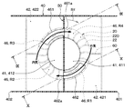
- FIG. 2 is a sectional view taken along line II-II in FIG. 1.
- FIG. 3 is a sectional view taken along line III-III in FIG. 2.
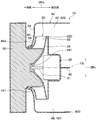
- FIG. 4 is an enlarged view of a portion IV in FIG. 2.
- FIG. 5 is a sectional view taken along line VV of FIG. 2.
- FIG. 6 is a VI-VI sectional view of FIG. 2.
- FIG. 7 is a sectional view taken along line VII-VII in FIG. 6. It is sectional drawing corresponding to FIG. 6 in the air blower of 2nd Embodiment.
- FIG. 9 is a sectional view taken along line IX-IX in FIG. 8.
- FIG. 9 is a sectional view taken along line XX of FIG.
- FIG. 12 is a sectional view taken along line XII-XII of FIG. 11. It is sectional drawing corresponding to FIG. 6 in the air blower of 4th Embodiment. It is sectional drawing corresponding to FIG. 5 in the air blower of 5th Embodiment.
- FIG. 15 is a sectional view taken along line XV-XV in FIG. 14. It is sectional drawing corresponding to FIG. 5 in the air blower of 6th Embodiment.
- FIG. 17 is a sectional view taken along line XVII-XVII of FIG. 16.
- the vehicle air conditioner is arranged inside a frontmost instrument panel in the vehicle compartment.
- the vehicle air conditioner is configured as an inside/outside air two-layer air conditioner capable of distinguishing the air sucked in from the outside of the vehicle compartment and the air sucked in from the vehicle compartment.
- the vehicle air conditioner circulates the inside air in the vehicle interior while blowing the outside air toward the inside of the window glass of the vehicle by using the inside air that is the air inside the vehicle as the first fluid and the outside air that is the air outside the vehicle as the second fluid.
- the inside/outside air two-layer mode can be implemented.
- the vehicle air conditioner includes an inside/outside air switching box and a temperature adjustment unit, which are not shown, in addition to the blower 10 of the present disclosure.
- the inside/outside air switching box takes in outside air and inside air.
- the inside/outside air switching box of the present embodiment is connected to the air flow upstream side of the blower 10.
- the inside/outside air switching box is formed with an outside air inlet for introducing outside air and an inside air inlet for introducing inside air.By adjusting the opening area of each inlet with the inside/outside air door, The amount introduced with and can be adjusted.
- the inside/outside air switching box multiple air passages are set so that the outside air and the inside air can be introduced separately.
- the plurality of air passages are partitioned by a partition plate so that air having different properties such as temperature or humidity can flow without being mixed.
- the temperature adjustment unit adjusts the temperature of the air blown into the passenger compartment.
- the temperature adjustment unit of the present embodiment is connected to the blower 10 on the downstream side of the air flow.
- the temperature adjustment unit is configured to include a cooling heat exchanger that cools air and a heating heat exchanger that heats air.
- a cooling heat exchanger for example, a vapor compression refrigeration cycle evaporator is adopted.
- the heating heat exchanger for example, a heater core that radiates engine cooling water is adopted.
- the temperature control unit includes a defroster outlet that blows air toward the inside of the window glass of the vehicle, a face outlet that blows air toward the upper body side of the passenger in the passenger compartment, and a lower body side of the passenger in the passenger compartment.
- a foot outlet or the like that blows air toward the air outlet is provided.
- the blower 10 is arranged between the inside/outside air switching box and the temperature adjustment unit.
- the blower 10 is configured such that the inside air is the first fluid and the outside air is the second fluid, and the inside air and the outside air can be distinguished and blown.
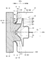
- the blower 10 includes a centrifugal fan 20, an electric motor 30 that drives the centrifugal fan 20, and a casing 40 that houses the centrifugal fan 20.
- the centrifugal fan 20 is a fan that rotates around the fan axis CL to blow out air sucked from one side of the fan axis CL in the axial direction DRa in a direction away from the fan axis CL.
- the centrifugal fan 20 is composed of a turbo fan having a characteristic that the static pressure is high among the centrifugal fans 20.
- the centrifugal fan 20 is not limited to the turbo fan, but may be a radial fan or a sirocco fan.
- the axial direction DRa is a direction extending along the fan axis CL.
- the radial direction DRr of the centrifugal fan 20 is a direction that is orthogonal to the fan axis CL and that extends radially around the fan axis CL.
- the centrifugal fan 20 has a plurality of blades 22, a shroud 24, and a fan boss 26.
- each blade 22, the shroud 24, and the fan boss 26 are configured as an integrally molded product made of resin.
- the centrifugal fan 20 is not limited to resin, and at least a part thereof may be made of a material other than resin (for example, a metal material).
- the plurality of blades 22 are arranged at regular intervals in the circumferential direction around a cylindrical space centered on the fan axis CL. In the centrifugal fan 20, each blade 22 rotates around the fan axis CL, so that air is sucked from one side of the fan axis CL.
- Each of the plurality of blades 22 has a one-side blade tip 221 which is an end on one side of the axial direction DRa and another blade tip 222 which is an end portion on the other side of the axial direction DRa.
- An inter-blade passage 220 through which air flows is formed between the plurality of blades 22.
- the shroud 24 is a member that connects parts of the blades 22 located on one side in the axial direction DRa.
- the shroud 24 is formed in a ring shape and is connected to one side of each blade 22 in the axial direction DRa. Specifically, the shroud 24 is connected to the one-side wing tip 221 of each blade 22.
- the shroud 24 has a shape having a spread in the radial direction DRr so as to cover one side of the blade 22 in the axial direction DRa.
- the fan boss 26 is a member that connects the parts of the blades 22 located on the other side in the axial direction DRa and is connected to the output shaft 31 of the electric motor 30.
- the fan boss 26 is formed in a disc shape.
- the fan boss 26 is connected to the other blade tip 222 of each blade 22.
- the inner part of the fan boss 26 in the fan radial direction DR projects to one side of the fan axial center CL as compared with the outer part in the fan radial direction DR.
- the fan boss 26 has an axisymmetric shape with the fan axis CL as the axis of symmetry.
- a boss portion 261 that connects the centrifugal fan 20 to the output shaft 31 of the electric motor 30 is provided at a substantially central portion of the fan boss 26.
- the electric motor 30 is an electric motor that drives the centrifugal fan 20 to rotate.
- the electric motor 30 is housed inside the casing 40.
- the output shaft 31 of the electric motor 30 is connected to the centrifugal fan 20.
- the rotational driving force of the electric motor 30 is transmitted to the centrifugal fan 20 via the output shaft 31, so that the centrifugal fan 20 rotates around the fan axis CL.
- the casing 40 is a member that forms the outer shell of the blower 10, and an air passage through which air flows is formed inside thereof.
- the casing 40 houses the centrifugal fan 20 and the electric motor 30 inside thereof.
- the casing 40 has a first suction port 401 and a second suction port 402 for sucking air introduced from the inside/outside air switching box, and blows the air blown from the centrifugal fan 20 to the temperature adjustment unit.
- An outlet 403 is formed.
- the first suction port 401 is a suction port that sucks the inside air that is the first fluid through the inside/outside air switching box in the inside/outside air two-layer mode.
- the second suction port 402 is a suction port that sucks the outside air, which is the second fluid, through the inside/outside air switching box in the inside/outside air two-layer mode.
- the first suction port 401 and the second suction port 402 are formed in a portion of the casing 40 located on one side of the centrifugal fan 20 in the axial direction DRa. Specifically, the first suction port 401 and the second suction port 402 are opened in a portion of the casing 40 that extends along the axial direction DRa. The first suction port 401 and the second suction port 402 are formed in portions of the casing 40 that face each other with the fan axis CL interposed therebetween.
- the outlet 403 is formed in a portion of the casing 40 located on the other side of the centrifugal fan 20 in the axial direction DRa. Specifically, the air outlet 403 is formed of a portion of the casing 40 that opens toward the other side in the axial direction DRa.
- a fluid suction passage 41 is formed on one side of the centrifugal fan 20 in the axial direction DRa, and a fluid outlet passage 42 is formed outside the centrifugal fan 20 in the radial direction DRr.
- the fluid suction passage 41 is an air passage for guiding the air sucked from the first suction opening 401 and the second suction opening 402 to the centrifugal fan 20.
- the fluid suction passage 41 is formed by a space located on one side of the centrifugal fan 20 in the axial direction DRa inside the casing 40.
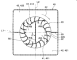
- the inlet-side partition section 50 includes a first suction passage 411 through which air (that is, a first fluid) sucked through the fluid suction passage 41 from the first suction port 401 flows, and air sucked through the second suction port 402 (that is, the first suction passage 411). It is a partition wall for partitioning into the second suction passage 412 through which the (two fluids) flow.
- the entrance-side partition section 50 is arranged at a distance from the centrifugal fan 20.
- the entrance-side partition section 50 is fixed to the inner wall surface of the casing 40 with an adhesive or the like so as not to rotate.
- the inlet-side partition portion 50 includes a base portion 51 that includes the fan axis CL and has a plate surface that extends along the axial direction DRa.
- the base portion 51 has one side portion in the axial direction DRa connected to the casing 40, and the other side portion in the axial direction DRa extends to the front of the substantially central portion of the fan boss 26 of the centrifugal fan 20.
- An enlarged portion 52 is connected to the base portion 51 at the other end in the axial direction DRa.
- the enlarged portion 52 is a disk-shaped member and is arranged at a predetermined distance from the fan boss 26 so as not to interfere with the fan boss 26.
- the entrance-side partition section 50 of this embodiment includes not only the base section 51 but also an expansion section 52. Therefore, it is possible to prevent the air flowing through the first suction passage 411 and the air flowing through the second suction passage 412 from being mixed with each other through the gap formed between the fan boss 26 and the fan boss 26.
- the fluid outlet passage 42 is an air passage for guiding the air blown out from the centrifugal fan 20 to the outlet 403.
- the fluid outlet passage 42 is formed inside the casing 40 by a space located outside of the centrifugal fan 20 in the radial direction DRr and a space located on the other side of the centrifugal fan 20 in the axial direction DRa. ..
- An outlet side partition portion 60 is arranged in the fluid outlet passage 42.
- the outlet side partition part 60 partitions the fluid outlet passage 42 into a first outlet passage 421 through which the first fluid blown out from the centrifugal fan 20 flows and a second outlet passage 422 through which the second fluid blown out from the centrifugal fan 20 flows. It is a partition for.
- the first outlet passage 421 is an air passage through which the first fluid sucked from the first suction passage 411 and passing through the blade passage 220 of the centrifugal fan 20 is blown out.
- the second outlet passage 422 is an air passage through which the second fluid sucked from the second inlet passage 412 and passing through the inter-blade passage 220 of the centrifugal fan 20 is blown out.
- the air flowing into the inter-blade passage 220 of the centrifugal fan 20 flows from the inlet of the inter-blade passage 220 toward the outlet thereof, while the centrifugal fan 20 rotates. Therefore, for example, as shown in FIG. 3, the inflow position of air into the inter-blade passage 220 and the outflow position of air from the inter-blade passage 220 are displaced in the rotational direction Rf of the centrifugal fan 20.
- the outflow position of the air from the inter-blade passage 220 is a position advanced in the rotation direction Rf of the centrifugal fan 20 with respect to the inflow position of the air into the inter-blade passage 220.
- the angle between the imaginary line connecting the outflow position of the air from the inter-blade passage 220 and the fan axis CL and the imaginary line connecting the inflow position of the air from the inter-blade passage 220 and the fan axis CL is blown out. Call it an angle.
- the blowout deviation angle can be specified by simulation, experiment, or the like.
- the centrifugal fan 20 of the present embodiment is designed so that the blowout deviation angle is about 90° when operated at the rotation speed assumed during normal operation.
- the outside air and the inside air that have flowed into the inter-blade passage 220 flow out from a position advanced by about 90° in the rotation direction Rf of the centrifugal fan 20.
- the outlet side partitioning portion 60 is controlled so as to suppress the inflow of the inside air into the second outlet passage 422 and the outside air into the first outlet passage 421 in the two-layer mode of the inside and outside air.
- the outlet-side partition portion 60 is arranged such that the angle ⁇ formed by the outlet-side partition portion 60 and the inlet-side partition portion 50 is the same as the blowout deviation angle.
- the virtual line L1 connecting the plate surface of the outlet-side partition 60 and the fan axis CL is the plate surface of the base 51 of the inlet-side partition 50 and the fan axis CL. It is arranged so as to form an angle equivalent to the blowout deviation angle with respect to the imaginary line L2 connecting with.
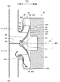
- the casing 40 has a shroud facing portion 44 that faces the shroud 24 of the centrifugal fan 20 with a predetermined gap.
- the shroud facing portion 44 is configured by a portion of the casing 40 that is located between the portion forming the fluid suction passage 41 and the shroud 24.
- the shroud facing portion 44 overlaps the portion of the casing 40 that forms the fluid suction passage 41 and the shroud 24 in the axial direction DRa.
- a predetermined gap is set between the shroud facing portion 44 and the shroud 24 so that the shroud 24 does not contact the shroud facing portion 44 when the centrifugal fan 20 rotates.
- the centrifugal fan 20 has a pressure difference between the air intake side and the air outlet side. That is, in the centrifugal fan 20, the pressure on the air intake side is lower than that on the air outlet side. As a result, as shown by the dotted arrow in FIG. 4, a part of the air blown from the centrifugal fan 20 can flow back to the suction side of the centrifugal fan 20 through the gap between the shroud 24 and the shroud facing portion 44. is there.
- the gap formed between the shroud 24 and the shroud facing portion 44 constitutes a backflow passage 46 that allows air to flow from the outlet side to the inlet side of the centrifugal fan 20.
- the air flowing through the backflow passage 46 is the air blown from the centrifugal fan 20 and has a rotation component in the rotation direction Rf of the centrifugal fan 20. Therefore, the air that has flowed into the reverse flow passage 46 from the outlet side of the centrifugal fan 20 advances in the rotation direction Rf of the centrifugal fan 20 when flowing through the reverse flow passage 46.
- the outflow position of air from the backflow passage 46 is a position advanced in the rotation direction Rf of the centrifugal fan 20 with respect to the inflow position of air into the backflow passage 46.
- the outflow position of the air from the backflow passage 46 is the same as the blowout deviation angle in the rotational direction Rf of the centrifugal fan 20 with respect to the inflow position of the air into the backflow passage 46. It tends to be in an advanced position.
- the inside air blown out from the centrifugal fan 20 may flow into the outside air suction side of the centrifugal fan 20 through the backflow passage 46.
- the window becomes liable to fog. If the window becomes fogged, the operation of the vehicle by the user will be hindered, so it must be avoided.
- one of the air flowing through the first blowout passage 421 and the air flowing through the second blowout passage 422 and the other air of the first suction passage 411 and the second suction passage 412 are provided.
- the structure is such that flow into the suction passage that is sucked is suppressed.
- a first fluid for guiding at least a part of the first fluid flowing through the reverse flow passage 46 to the first suction passage 411.
- a fluid bypass passage 461 is provided.
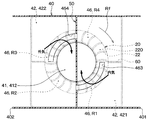
- the backflow passage 46 is formed in the first region R1 and the second region 421 based on the positional relationship between the first suction passage 411 and the second suction passage 412 and the first outlet passage 421 and the second outlet passage 422. It is divided into four regions, a region R2, a third region R3, and a fourth region R4.
- the region where the first outlet passage 421 is located outside the first suction passage 411 in the radial direction DRr is defined as the first region R1, and the first outlet passage 421 is disposed outside the second suction passage 412 in the radial direction DRr.
- the region where is located is referred to as a second region R2.
- a region where the second outlet passage 422 is located outside the second suction passage 412 in the radial direction DRr is defined as a third region R3, and the second outlet is provided outside the first suction passage 411 in the radial direction DRr.
- a region where the passage 422 is located is referred to as a fourth region R4.
- the blower 10 has a structure in which the reverse flow passage 46 overlaps the fluid suction passage 41 and the fluid discharge passage 42 in the axial direction DRa.
- the first region R1 overlaps with the first suction passage 411 and the first blowout passage 421 in the axial direction DRa
- the third region R3 has the second suction passage 412 and the second blowout passage in the axial direction DRa.
- the structure is such that it overlaps with the passage 422.
- the second region R2 overlaps with the second suction passage 412 and the first outlet passage 421 in the axial direction DRa
- the fourth region R4 overlaps with the first suction passage 411 and the second outlet passage 422 in the axial direction DRa. It has a structure that overlaps.
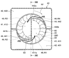
- the third region R3 of the backflow passage 46 is a region that advances in the rotation direction Rf of the centrifugal fan 20 with respect to the first outlet passage 421, and the first fluid flowing through the first outlet passage 421 may flow in.
- the third region R3 of the backflow passage 46 is continuous with the second suction passage 412, and the first fluid tends to flow into the second suction passage 412 via the backflow passage 46.
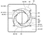
- the first fluid bypass passage 461 is provided in the shroud facing portion 44 at a portion forming the third region R3 of the backflow passage 46.
- the first fluid bypass passage 461 of the present embodiment is configured to guide the fluid flowing in the third region R3 of the reverse flow passage 46 to the first suction passage 411.
- the first fluid bypass passage 461 is configured by an arcuate passage extending along the rotation direction Rf of the centrifugal fan 20.
- the first fluid bypass passage 461 is located in a portion of the shroud facing portion 44 forming the third region R3 from a position where the base portion 51 of the inlet-side partition portion 50 is set, and from the base portion 51 to the rotation direction of the centrifugal fan 20. It is provided in a range up to a position delayed by about 60° from Rf. That is, the first fluid bypass passage 461 extends from the vicinity of the base portion 51 of the inlet-side partitioning portion 50 to the rotation direction Rf of the centrifugal fan 20 in the portion forming the third region R3 of the shroud facing portion 44. Is provided in a range up to a position advanced by about 60° in the opposite direction.
- the first fluid bypass passage 461 is configured by a portion of a portion of the shroud facing portion 44 that forms the third region R3 bulged to one side in the axial direction DRa. ..
- an outlet hole 461a serving as a passage outlet is formed in the base portion 51 of the inlet-side partition portion 50. Since the passage height in the axial direction DRa of the first fluid bypass passage 461 is sufficiently larger than the passage height of the backflow passage 46, the fluid flowing through the third region R3 of the backflow passage 46 easily flows. Is becoming
- the centrifugal fan 20 when the centrifugal fan 20 is driven by the electric motor 30 in the inside/outside air two-layer mode, as shown in FIG. 1, the inside air is sucked from the first suction port 401 and the outside air is discharged. It is sucked in through the second suction port 402.
- the inside air sucked from the first suction port 401 flows into the inter-blade passage 220 of the centrifugal fan 20 via the first suction passage 411.
- the outside air sucked from the second suction port 402 flows into the centrifugal fan 20 via the second suction passage 412. Since the first suction passage 411 and the second suction passage 412 are partitioned by the inlet-side partitioning portion 50, the outside air and the inside air hardly mix in the fluid suction passage 41 and flow into the inter-blade passage 220.
- the outside air and the inside air that have flowed into the centrifugal fan 20 flow from the inlet to the outlet of the inter-blade passage 220, the inside air is blown out to the first outlet passage 421, and the outside air is discharged to the second outlet passage. It is blown out to 422.
- the inside air blown into the first blow passage 421 is adjusted to a desired temperature inside the temperature adjustment unit, and then blown toward the occupants in the passenger compartment.
- the outside air blown into the second blowing passage 422 is adjusted to a desired temperature inside the temperature adjusting unit and then blown toward the inside of the window glass of the vehicle. This makes it possible to prevent window fogging and reduce the air conditioning load.
- a part of the inside air blown into the first blowing passage 421 flows into the backflow passage 46.
- the inflow of the inside air into the backflow passage 46 may be a factor that causes the inside air and the outside air to be mixed on the suction side of the centrifugal fan 20.
- the first fluid bypass passage 461 is provided in the shroud facing portion 44 forming the backflow passage 46. Therefore, as shown in FIG. 6 and FIG. 7, even if a part of the inside air blown out from the first outlet passage 421 flows into the backflow passage 46, the inside air passes through the first fluid bypass passage 461. 1 Suction passage 411 flows. That is, it is possible to prevent a part of the inside air blown from the first blow passage 421 from flowing into the second suction passage 412 via the backflow passage 46.
- the inside air blown out from the first outlet passage 421 may flow to the second suction passage 412 into which the outside air is sucked. Suppressed. As a result, the mixing of the inside air and the outside air due to the backflow of the inside air is suppressed, so that the separability of the inside air and the outside air in the blower 10 can be improved.
- the inside air is suppressed from flowing into the second suction passage 412 into which the outside air is sucked, so that the centrifugal fan 20 is supplied with the outside air having low humidity.
- low-humidity air that is, outside air
- the inside/outside air two-layer mode low-humidity air (that is, outside air) is blown toward the inside of the window glass of the vehicle, so that sufficient antifogging performance can be exhibited.
- the first fluid bypass passage 461 is provided in the portion of the shroud facing portion 44 that forms the third region R3 of the backflow passage 46, but is not limited thereto. Not done. In the backflow passage 46, the first fluid flowing through the first outlet passage 421 may flow into not only the third region R3 but also the second region R2 that is continuous with the second suction passage 412. Therefore, the first fluid bypass passage 461 is provided so as to straddle not only the portion forming the third region R3 of the backflow passage 46 but also the portion forming the second region R2 in the shroud facing portion 44. May be.
- a second fluid for guiding at least a part of the second fluid flowing through the backflow passage 46 to the second suction passage 412.
- a bypass passage 462 is provided in the shroud facing portion 44.
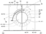
- the first fluid bypass passage 461 has the same configuration as that described in the first embodiment, as shown in FIG. 9.
- the first region R1 of the backflow passage 46 is a region that advances in the rotation direction Rf of the centrifugal fan 20 with respect to the second outlet passage 422, and the second fluid flowing through the second outlet passage 422 may flow in.
- the first region R1 of the backflow passage 46 is continuous with the first suction passage 411, and the second fluid tends to flow into the first suction passage 411 through the backflow passage 46.
- the second fluid bypass passage 462 is provided in the portion of the shroud facing portion 44 that forms the first region R1 of the backflow passage 46.
- the second fluid bypass passage 462 of the present embodiment is configured to guide the fluid flowing in the first region R1 of the reverse flow passage 46 to the second suction passage 412.
- the second fluid bypass passage 462 is configured by an arcuate passage extending along the rotation direction Rf of the centrifugal fan 20.
- the second fluid bypass passage 462 extends from the position where the base portion 51 of the inlet-side partition portion 50 is set in the portion forming the first region R1 of the shroud facing portion 44 to the rotation direction of the centrifugal fan 20 from the base portion 51. It is provided in a range up to a position delayed by about 60° from Rf. That is, the second fluid bypass passage 462 extends from the vicinity of the base portion 51 of the inlet side partition portion 50 to the rotation direction Rf of the centrifugal fan 20 in the portion forming the first region R1 of the shroud facing portion 44. Is provided in a range up to a position advanced by about 60° in the opposite direction.
- the second fluid bypass passage 462 is configured by a part of the shroud facing portion 44 that forms the first region R ⁇ b>1 and that bulges to one side in the axial direction DRa. ..
- an outlet hole 462a serving as a passage outlet is formed in the base portion 51 of the inlet-side partition portion 50. Since the passage height in the axial direction DRa of the second fluid bypass passage 462 is sufficiently larger than the passage height of the backflow passage 46, the second fluid bypass passage 462 has a structure in which the fluid flowing through the first region R1 of the backflow passage 46 easily flows. Is becoming
- blower 10 of the present embodiment has the same configuration as the blower 10 described in the first embodiment, it is possible to obtain the same effect as that of the first embodiment.
- the blower 10 of the present embodiment not only the first fluid bypass passage 461 but also the second fluid bypass passage 462 is provided for the shroud facing portion 44. According to this, the outside air blown out from the second outlet passage 422 is suppressed from flowing into the first intake passage 411 into which the inside air is sucked. As a result, the mixing of the inside air and the outside air due to the backflow of the outside air is suppressed, so that the separability of the inside air and the outside air in the blower 10 can be improved.
- the blower 10 of the present embodiment suppresses the outside air from flowing into the first suction passage 411 into which the inside air is sucked, it is possible to realize efficient air conditioning with reduced ventilation loss. That is, the blower 10 of the present embodiment can achieve both the securing of anti-fogging performance and the efficient air conditioning with suppressed ventilation loss.
- the second fluid bypass passage 462 is illustrated as being provided in the portion of the shroud facing portion 44 that forms the first region R1 of the backflow passage 46, but is not limited thereto. Not done. In the backflow passage 46, the second fluid flowing in the second outlet passage 422 may flow not only into the first region R1 but also into the fourth region R4 continuous with the first suction passage 411. Therefore, the second fluid bypass passage 462 is provided so as to straddle not only the portion of the backflow passage 46 that forms the first region R1 but also the portion that forms the fourth region R4 of the shroud facing portion 44. May be.
- the first fluid bypass passage 461 and the second fluid bypass passage 462 are formed for the shroud facing portion 44, but the invention is not limited to this.
- the blower 10 may have a structure in which only one of the first fluid bypass passage 461 and the second fluid bypass passage 462 is provided for the shroud facing portion 44, for example.
- the present embodiment is different from the first embodiment in that a first fluid communication hole 463 that communicates the first suction passage 411 and the first outlet passage 421 with the shroud facing portion 44 is formed. ..
- parts different from the first embodiment will be mainly described, and description of the same parts as the first embodiment may be omitted.
- the shroud facing portion 44 is provided with a first fluid communication hole 463 instead of the first fluid bypass passage 461.
- the first fluid communication hole 463 is a through hole that penetrates in the axial direction DRa.
- the first region R1 of the reverse flow passage 46 is a region where the first blowout passage 421 is located outside the radial direction DRr of the first suction passage 411, and the first fluid flowing through the first blowout passage 421 flows in. Since the first fluid that has flowed into the first region R1 has a rotational component in the rotational direction Rf of the centrifugal fan 20, it advances in the rotational direction Rf of the centrifugal fan 20 due to this rotational component and flows into the second suction passage 412. try to.
- the first region R1 is a region that overlaps the first suction passage 411 and the first outlet passage 421 in the axial direction DRa. Therefore, the first fluid communication hole 463 is provided in a portion of the shroud facing portion 44 that forms the first region R1 of the backflow passage 46.
- the first fluid communication hole 463 has a hole shape that extends in an arc shape along the rotation direction Rf of the centrifugal fan 20.
- the communication hole 463 for the first fluid is located in the portion forming the first region R1 of the shroud facing portion 44, from the position where the base portion 51 of the inlet side partition portion 50 is set to the rotation direction of the centrifugal fan 20 from the base portion 51. It is provided in a range up to a position delayed by about 90° from Rf. That is, the first fluid communication hole 463 is formed in the portion forming the first region R1 of the shroud facing portion 44 from the vicinity of the base portion 51 of the inlet side partition portion 50 to the rotation direction Rf of the centrifugal fan 20 from the base portion 51. Are provided in a range up to a position advanced by about 90° in the opposite direction.
- the blower 10 of the present embodiment is provided with a first fluid communication hole 463 for communicating the first suction passage 411 and the first blowout passage 421 with the shroud facing portion 44.
- the inside air is first sucked through the first fluid communication hole 463. It flows into the passage 411. That is, it is possible to prevent a part of the inside air blown from the first blow passage 421 from flowing into the second suction passage 412 via the backflow passage 46. As a result, the mixing of the inside air and the outside air due to the backflow of the inside air is suppressed, so that the separability of the inside air and the outside air in the blower 10 can be improved.
- the first fluid communication hole 463 is in the range from the position where the base portion 51 of the inlet-side partition portion 50 is set to the position which is delayed by about 90° in the rotational direction Rf of the centrifugal fan 20.
- the provided ones are illustrated, but the present invention is not limited to this.
- the first fluid communication hole 463 may have a shape and range other than those exemplified in the third embodiment as long as it is provided in the first region R1 of the shroud facing portion 44.
- the first fluid communication hole 463 is formed in the shroud facing portion 44 instead of the first fluid bypass passage 461, but the invention is not limited thereto. ..
- the blower 10 may have a structure in which the first fluid bypass passage 461 and the first fluid communication hole 463 are provided in the shroud facing portion 44, for example.
- a fourth embodiment will be described with reference to FIG.
- the present embodiment is different from the third embodiment in that a second fluid communication hole 464 that connects the second suction passage 412 and the second outlet passage 422 to the shroud facing portion 44 is formed. ..
- the shroud facing portion 44 is provided with a second fluid communication hole 464 in addition to the first fluid communication hole 463.
- the second fluid communication hole 464 is a through hole that penetrates in the axial direction DRa.
- the third region R3 of the backflow passage 46 is a region in which the second outlet passage 422 is located outside the second suction passage 412 in the radial direction DRr, and the second fluid flowing through the second outlet passage 422 flows in. Since the second fluid that has flowed into the second region R2 has a rotational component in the rotational direction Rf of the centrifugal fan 20, it advances in the rotational direction Rf of the centrifugal fan 20 due to this rotational component and flows into the first suction passage 411. try to.
- the second region R2 is a region that overlaps the second suction passage 412 and the second outlet passage 422 in the axial direction DRa. Therefore, the second fluid communication hole 464 is provided in a portion of the shroud facing portion 44 that forms the third region R3 of the backflow passage 46.
- the second fluid communication hole 464 has a hole shape that extends in an arc shape along the rotation direction Rf of the centrifugal fan 20.
- the second fluid communication hole 464 is formed in the rotation direction of the centrifugal fan 20 from the position where the base portion 51 of the inlet-side partition portion 50 is set in the portion forming the third region R3 of the shroud facing portion 44. It is provided in a range up to a position delayed by about 90° from Rf. That is, the second fluid communication hole 464 is located in the portion forming the third region R3 of the shroud facing portion 44, from the vicinity of the base portion 51 of the inlet side partition portion 50 to the rotation direction Rf of the centrifugal fan 20 from the base portion 51. Are provided in a range up to a position advanced by about 90° in the opposite direction.
- blower 10 of the present embodiment is provided with a second fluid communication hole 464 that communicates the second suction passage 412 and the second outlet passage 422 with the shroud facing portion 44.
- the outside air flows into the second suction passage 412 via the second fluid communication hole 464. That is, it is possible to prevent a part of the outside air blown from the second blow passage 422 from flowing into the first suction passage 411 via the backflow passage 46. As a result, the mixing of the inside air and the outside air due to the backflow of the outside air is suppressed, so that the separability of the inside air and the outside air in the blower 10 can be improved.
- the second fluid communication hole 464 is in the range from the position where the base portion 51 of the inlet-side partition portion 50 is set to the position which is delayed by about 90° in the rotational direction Rf of the centrifugal fan 20.
- the provided ones are illustrated, but the present invention is not limited to this.
- the second fluid communication hole 464 may have a shape and range other than those exemplified in the fourth embodiment as long as it is provided in the third region R3 of the shroud facing portion 44.
- the first fluid communication hole 463 and the second fluid communication hole 464 are formed in the shroud facing portion 44, but the invention is not limited thereto.
- the blower 10 may have a structure in which only one of the first fluid communication hole 463 and the second fluid communication hole 464 is formed in the shroud facing portion 44, for example.
- FIGS. 14 and 15 a fifth embodiment will be described with reference to FIGS. 14 and 15.
- This embodiment differs from the first embodiment in that a fluid guide 241 is formed for the shroud 24.
- parts different from the first embodiment will be mainly described, and description of the same parts as the first embodiment may be omitted.
- the shroud 24 has a plurality of fluid guides 241 formed therein.
- the first fluid bypass passage 461 described in the first embodiment is not formed for the shroud facing portion 44.
- the fluid guide 241 guides the first fluid flowing from the first outlet passage 421 to the backflow passage 46 to the first suction passage 411, and guides the second fluid flowing from the second outlet passage 422 into the second suction passage 421. 412.
- the fluid guide 241 projects toward the shroud facing portion 44.
- the fluid guide 241 is located at a position where the inner end 242 located on the fluid suction passage 41 side advances in the direction opposite to the rotational direction Rf of the centrifugal fan 20 with respect to the outer end 243 located on the fluid outlet passage 42 side. It has a shape. That is, the fluid guide 241 has a shape such that the inner end 242 located on the fluid suction passage 41 side is behind the outer end 243 located on the fluid outlet passage 42 side in the rotational direction Rf of the centrifugal fan 20. Is becoming
- the inner end portion 242 located on the air outlet side of the backflow passage 46 has a rotation direction Rf of the centrifugal fan 20 with respect to the outer end portion 243 located on the air inlet side of the backflow passage 46. It has been set to a position behind.
- an angle ⁇ formed by an imaginary line L3 connecting the inner end 242 and the fan axis CL and an imaginary line L4 connecting the outer end 243 and the fan axis CL becomes a backflow deviation angle.
- the positions of the inner end portion 242 and the outer end portion 243 are set.
- the fluid guide 241 is set so that the direction extending from the outer end 243 toward the inner end 242 is opposite to the rotation direction Rf of the centrifugal fan 20. That is, the fluid guide 241 has a curved shape so that the inflow position of the air into the reverse flow passage 46 is behind the outflow position of the air in the rotation direction Rf of the centrifugal fan 20.
- the blower 10 guides the first fluid, which has flowed into the backflow passage 46 from the first outlet passage 421, to the first suction passage 411 with respect to the shroud 24, and the second fluid which has flowed into the backflow passage 46 from the second outlet passage 422.
- a fluid guide 241 for guiding the fluid to the second suction passage 412 is provided.
- the inside air is guided to the first suction passage 411 by the fluid guide 241. That is, it is possible to prevent a part of the inside air blown from the first blow passage 421 from flowing into the second suction passage 412 via the backflow passage 46.
- the outside air is guided to the second suction passage 412 by the fluid guide 241. That is, it is possible to prevent a part of the outside air blown from the second blow passage 422 from flowing into the first suction passage 411 via the backflow passage 46.
- the mixing of the inside air and the outside air due to the backflow of the inside air and the outside air is suppressed, so that the separability of the inside air and the outside air in the blower 10 can be improved.
- the fifth embodiment described above exemplifies the one in which the plurality of fluid guides 241 are formed on the shroud facing portion 44, but the present invention is not limited to this.
- the blower 10 may have at least one fluid guide 241 formed on the shroud facing portion 44.
- the fluid guide 241 is curved so that the inflow position of the air into the reverse flow passage 46 is behind the outflow position of the air in the rotational direction Rf of the centrifugal fan 20.
- the shape is not limited to this. If the fluid guide 241 can suppress the mixture of the inside air and the outside air due to the backflow of the inside air and the outside air, for example, the inflow position of the air into the backflow passage 46 is the rotational direction Rf of the centrifugal fan 20 with respect to the outflow position of the air.
- the shape may be such that the position is advanced to.
- FIGS. 10-12 a sixth embodiment will be described with reference to FIGS.
- the present embodiment is different from the first embodiment in that a first fluid guide 441 and a second fluid guide 442 are provided for the shroud facing portion 44.
- parts different from the first embodiment will be mainly described, and description of the same parts as the first embodiment may be omitted.
- the shroud facing portion 44 is provided with a first fluid guide 441 and a second fluid guide 442.
- the first fluid bypass passage 461 described in the first embodiment is not formed for the shroud facing portion 44.
- the first fluid guide 441 guides the first fluid flowing from the first outlet passage 421 to the backflow passage 46 to the first suction passage 411.
- the first fluid guide 441 projects toward the shroud 24.
- the first fluid guide 441 is provided at a portion of the backflow passage 46 that forms the second region R2.
- the rotation direction Rf of the centrifugal fan 20 with respect to the first fluid outer end 441b located on the fluid blow-out passage 42 side is defined by the first fluid inner end 441a located on the fluid suction passage 41 side.
- the shape is such that it moves in the opposite direction to. That is, the first fluid guide 441 rotates the centrifugal fan 20 with respect to the first fluid outer end 441b located on the fluid outlet passage 42 side of the first fluid inner end 441a located on the fluid suction passage 41 side.
- the shape is such that the position is delayed in the direction Rf.
- the inner end portion 441a for the first fluid is set at a position close to the base portion 51 of the inlet-side partition portion 50 among the portions forming the second region R2 of the shroud facing portion 44.
- the first fluid outer end portion 441b is set at a position close to the outlet side partition portion 60 in a portion forming the second region R2 of the shroud facing portion 44. That is, the inner end portion 441a for the first fluid is set at a position behind the outer end portion 441b for the first fluid by about 90° in the rotation direction Rf of the centrifugal fan 20.
- the first fluid guide 441 is set so that the direction extending from the first fluid outer end 441b toward the first fluid inner end 441a is opposite to the rotation direction Rf of the centrifugal fan 20. That is, the first fluid guide 441 has a curved shape so that the inflow position of the air into the reverse flow passage 46 is behind the outflow position of the air in the rotation direction Rf of the centrifugal fan 20.
- the second fluid guide 442 guides the second fluid flowing from the second outlet passage 422 into the reverse flow passage 46 to the second suction passage 412.
- the second fluid guide 442 projects toward the shroud 24.
- the second fluid guide 442 is provided in a portion of the backflow passage 46 that forms the fourth region R4.
- the second fluid guide 442 has a second fluid inner end 442a located on the fluid suction passage 41 side with respect to a second fluid outer end 442b located on the fluid outlet passage 42 side.
- the shape is such that it moves in the opposite direction to. That is, the second fluid guide 442 rotates the centrifugal fan 20 with respect to the second fluid outer end 442b located on the fluid outlet passage 42 side, while the second fluid inner end 442a located on the fluid suction passage 41 side rotates.
- the shape is such that the position is delayed in the direction Rf.
- the inner end portion 442a for the second fluid is set at a position of the portion forming the fourth region R4 of the shroud facing portion 44, which is close to the base portion 51 of the inlet side partition portion 50.
- the second fluid outer end portion 442b is set at a position close to the outlet side partition portion 60 in the portion forming the fourth region R4 of the shroud facing portion 44. That is, the inner end portion 442a for the second fluid is set at a position delayed by about 90° in the rotation direction Rf of the centrifugal fan 20 with respect to the outer end portion 442b for the second fluid.
- the second fluid guide 442 is set such that the direction extending from the second fluid outer end 442b toward the second fluid inner end 442a is opposite to the rotation direction Rf of the centrifugal fan 20. That is, the second fluid guide 442 has a curved shape so that the inflow position of the air into the reverse flow passage 46 is behind the outflow position of the air in the rotation direction Rf of the centrifugal fan 20.
- the blower 10 is provided with a first fluid guide 441 for the shroud facing portion 44, which guides the first fluid flowing from the first outlet passage 421 into the backflow passage 46 to the first suction passage 411. Further, the blower 10 is provided with a second fluid guide 442 for the shroud facing portion 44, which guides the second fluid flowing from the second outlet passage 422 into the backflow passage 46 to the second suction passage 412.
- the inside air is guided to the first suction passage 411 by the first fluid guide 441. That is, it is possible to prevent a part of the inside air blown from the first blow passage 421 from flowing into the second suction passage 412 via the backflow passage 46.
- the outside air is guided to the second suction passage 412 by the second fluid guide 442. That is, it is possible to prevent a part of the outside air blown from the second blow passage 422 from flowing into the first suction passage 411 via the backflow passage 46.
- the mixing of the inside air and the outside air due to the backflow of the inside air and the outside air is suppressed, so that the separability of the inside air and the outside air in the blower 10 can be improved.
- the shroud facing portion 44 is provided with the first fluid guide 441 and the second fluid guide 442, but the shroud facing portion 44 is not limited to this.
- the blower 10 may have a structure in which only one of the first fluid guide 441 and the second fluid guide 442 is provided for the shroud facing portion 44, for example.
- the first fluid is the inside air and the second fluid is the outside air
- the first fluid and the second fluid are not limited to this.
- the first fluid may be outside air and the second fluid may be inside air.
- the outside air flows through the first suction passage 411 and the first outlet passage 421, and the inside air flows through the second suction passage 412 and the second outlet passage 422.
- the vehicle air conditioner may have, for example, a configuration in which a temperature adjusting unit is arranged on the upstream side of the air flow of the blower 10. Further, the vehicle air conditioner may be configured such that the cooling heat exchanger is arranged upstream of the air flow of the blower 10 and the heating heat exchanger is arranged downstream of the air flow of the blower 10. Good.
- blower 10 of the present disclosure is applied to a vehicle air conditioner
- the application target of the blower 10 is not limited to this.
- the blower 10 of the present disclosure can be widely applied to a device (for example, a humidifier) that needs to avoid mixing fluids having different temperatures and humidity.
- the blower is configured so that the fluid flows from the fluid outlet passage toward the fluid inlet passage between the shroud of the centrifugal fan and the shroud facing portion of the casing.
- a backflow passage is formed.
- the backflow passage is a suction passage in which one of the first fluid flowing through the first blow passage and the second fluid flowing through the second blow passage receives the other fluid of the first suction passage and the second suction passage. It is structured so that it can be prevented from flowing into.
- the shroud facing portion is provided with the first fluid bypass passage for guiding at least a part of the first fluid flowing through the backflow passage to the first suction passage.
- at least a part of the first fluid flowing in the backflow passage flows into the first suction passage from the backflow passage, so that the first fluid is suppressed from flowing into the second suction passage.
- the mixing of the first fluid and the second fluid in the second suction passage is suppressed, so that the separability of the first fluid and the second fluid in the blower can be improved.
- the shroud facing portion is provided with a second fluid bypass passage for guiding at least a part of the second fluid flowing through the backflow passage to the second suction passage.
- at least a part of the second fluid flowing through the backflow passage flows into the second suction passage from the backflow passage, so that the second fluid is suppressed from flowing into the first suction passage.
- the mixing of the first fluid and the second fluid in the first suction passage is suppressed, so that the separability of the first fluid and the second fluid in the blower can be improved.
- the shroud facing portion is formed with a first fluid communication hole that communicates at least a part of a region in which the first fluid flows in the backflow passage with the first suction passage. ..
- the first fluid flowing through the backflow passage flows into the first suction passage through the first fluid communication hole, so that the first fluid is suppressed from flowing into the second suction passage.
- the mixing of the first fluid and the second fluid in the second suction passage is suppressed, so that the separability of the first fluid and the second fluid in the blower can be improved.
- the shroud facing portion has a first fluid communication hole that communicates a region in which the first fluid flows in the backflow passage and the first suction passage, and a second fluid in the backflow passage.
- a communication hole for the second fluid is formed that connects the region in which is flowing and the second suction passage.
- At least a part of the first fluid flowing through the backflow passage flows into the first suction passage through the first fluid communication hole, so that the first fluid is suppressed from flowing into the second suction passage.
- at least a part of the second fluid flowing through the backflow passage flows into the second suction passage via the communication hole for the second fluid, so that the first fluid is suppressed from flowing into the second suction passage.
- the blower guides the first fluid, which has flowed into the backflow passage from the first outlet passage, into the shroud, while introducing the second fluid, which has flowed into the backflow passage from the second outlet passage, into the first suction passage.
- At least one fluid guide that leads to the second suction passage is formed.
- the fluid guide projects toward the shroud facing portion, and the inner end located on the fluid suction passage side advances in the direction opposite to the rotation direction of the centrifugal fan with respect to the outer end located on the fluid discharge passage side.
- the first fluid flowing into the backflow passage is guided to the first suction passage by the first fluid guide formed in the shroud, so that the first fluid is suppressed from flowing into the second suction passage.
- the second fluid flowing into the backflow passage is guided to the second suction passage by the second fluid guide formed in the shroud, so that the second fluid is suppressed from flowing into the first suction passage.
- the shroud facing portion is provided with a first fluid guide that guides the first fluid that has flowed into the reverse flow passage from the first blow passage to the first suction passage.
- the first fluid guide projects toward the shroud facing portion, and an inner end portion of the first fluid located on the fluid suction passage side of the first fluid guide of the centrifugal fan with respect to an outer end portion of the first fluid located on the fluid outlet passage side.
- the shape is such that the position advances in the direction opposite to the rotation direction.
- the first fluid that has flowed into the backflow passage is guided to the first suction passage by the first fluid guide formed in the shroud facing portion, so that the first fluid is suppressed from flowing into the second suction passage. ..
- the mixing of the first fluid and the second fluid in the second suction passage is suppressed, so that the separability of the first fluid and the second fluid in the blower can be improved.
- the shroud facing portion is formed with a second fluid guide that guides the second fluid that has flowed into the backflow passage from the second outlet passage to the second suction passage.
- the second fluid guide projects toward the shroud facing portion, and the inner end of the second fluid located on the fluid suction passage side of the second fluid guide of the centrifugal fan with respect to the outer end of the second fluid located on the fluid discharge passage side.
- the shape is such that the position advances in the direction opposite to the rotation direction.
- the second fluid flowing into the backflow passage is guided to the second suction passage by the second fluid guide formed in the shroud facing portion, so that the second fluid is suppressed from flowing into the first suction passage. ..
- the mixing of the first fluid and the second fluid in the first suction passage is suppressed, so that the separability of the first fluid and the second fluid in the blower can be improved.
- a blower is applied to a vehicle air conditioner capable of performing an inside/outside air two-layer mode in which outside air is introduced from the outside of the vehicle compartment while the inside air introduced from the inside of the vehicle compartment is circulated in the vehicle interior.
- the first fluid is one of outside air and inside air.
- the second fluid is the other of the outside air and the inside air.
- the blower it is possible to suppress the mixture of the inside air and the outside air in the blower.
- the inflow of the inside air into the suction passage that sucks the outside air it is possible to supply low-humidity air (that is, outside air) toward the inside of the window glass for the vehicle.
- the ventilation loss is reduced and the air conditioning efficiency by the inside air circulation is improved, so that the efficient air conditioning can be realized.
Abstract
This fan (10) comprises: a centrifugal fan (20); and a casing (40) having the centrifugal fan housed therein. The fan (10) comprises: an intake-side partition (50) which partitions a fluid suction passage (41) into a first suction passage (411) and a second suction passage (412); and an outlet-side partition (60) which partitions a fluid blowing passage (42) into a first blowing passage (421) and a second blowing passage (422). The casing includes a shroud-facing portion (44) which faces a shroud (24) of the centrifugal fan with a predetermined interval therebetween, and which forms a reverse flow passage (46) through which a first fluid and a second fluid flow from the fluid blowing passage between the shroud, towards the fluid suction passage. The reverse flow passage has a structure which curbs one of either the first fluid which flows through the first blowing passage or the second fluid which flows through the second blowing passage from flowing into the suction passage into which the other fluid is sucked, that being the other of the first suction passage and the second suction passage.
Description
本出願は、2018年12月5日に出願された日本特許出願番号2018-228405号に基づくもので、ここにその記載内容が参照により組み入れられる。
This application is based on Japanese Patent Application No. 2018-228405 filed on December 5, 2018, the description of which is incorporated herein by reference.
本開示は、第1流体と第2流体を吸い込んで吹き出す送風機に関する。
The present disclosure relates to a blower that sucks in and blows out a first fluid and a second fluid.
従来、異なる温度の空気を区別して送風するために、遠心ファンの吸込側および吹出側それぞれに仕切部材が設けられた送風機が知られている(例えば、特許文献1参照)。この特許文献1には、空気を吸い込んでから吹き出すまでの遠心ファンの回転角度を考慮して、遠心ファンの吸込側の仕切部材および吹出側の仕切部材の相対位置を遠心ファンの回転方向にずらした送風機が開示されている。
Conventionally, there has been known a blower in which partition members are provided on the suction side and the blowing side of a centrifugal fan in order to separately blow air of different temperatures (for example, see Patent Document 1). In this patent document 1, the relative position of the partition member on the suction side and the partition member on the outlet side of the centrifugal fan is shifted in the rotational direction of the centrifugal fan in consideration of the rotation angle of the centrifugal fan from the time of sucking air to the time of blowing air. A blower is disclosed.
ところで、遠心ファンは、空気の吸込側と吹出側に圧力差が生ずるため、遠心ファンから吹き出された空気の一部が、遠心ファンと遠心ファンを収容するケーシングとの隙間を介して遠心ファンの吸込側に逆流することがある。この場合、遠心ファンと遠心ファンを収容するケーシングとの隙間が、遠心ファンの吹出側から吸込側に空気が流れる逆流通路を構成する。
By the way, since the centrifugal fan has a pressure difference between the suction side and the blowing side of the air, a part of the air blown out from the centrifugal fan passes through the gap between the centrifugal fan and the casing housing the centrifugal fan so that a part of the centrifugal fan is discharged. May flow back to the suction side. In this case, the gap between the centrifugal fan and the casing containing the centrifugal fan constitutes a backflow passage through which air flows from the blow side to the suction side of the centrifugal fan.
また、遠心ファンから吹き出された空気は遠心ファンの回転方向の回転成分を有しており、遠心ファンの吹出側から逆流通路に流入した空気が逆流通路を流れる際に遠心ファンの回転方向に進む。
Further, the air blown out from the centrifugal fan has a rotation component in the rotation direction of the centrifugal fan, and when the air flowing into the backflow passage from the blowout side of the centrifugal fan flows in the backflow passage, it advances in the rotation direction of the centrifugal fan. ..
このため、例えば、遠心ファンによって温度が異なる第1流体と第2流体とを区別して送風しようとしても、遠心ファンから吹き出された第1流体が、逆流通路を介して遠心ファンにおける第2流体の吸込側に流れ込んでしまう可能性がある。また、遠心ファンから吹き出された第2流体が、逆流通路を介して遠心ファンにおける第1流体の吸込側に流れ込んでしまう可能性もある。
Therefore, for example, even if an attempt is made to separate the first fluid and the second fluid having different temperatures by the centrifugal fan to blow the air, the first fluid blown out from the centrifugal fan passes through the backflow passage and becomes the second fluid in the centrifugal fan. It may flow into the suction side. Further, the second fluid blown out from the centrifugal fan may flow into the suction side of the first fluid in the centrifugal fan via the backflow passage.
つまり、従来技術では、遠心ファンの吹出側から吸込側への流体の逆流による第1流体と第2流体との混合を抑えることができず、送風機における第1流体と第2流体との分離性が低い。これらは、本発明者らの鋭意検討の末に見出された知見である。
本開示は、第1流体と第2流体を吸い込んで吹き出す送風機において、第1流体と第2流体との分離性の向上を図ることを目的とする。 That is, in the prior art, it is not possible to suppress the mixing of the first fluid and the second fluid due to the reverse flow of the fluid from the outlet side to the inlet side of the centrifugal fan, and the separability of the first fluid and the second fluid in the blower is suppressed. Is low. These are the findings that have been found after intensive studies by the present inventors.
The present disclosure aims to improve the separability of the first fluid and the second fluid in a blower that sucks in and blows out the first fluid and the second fluid.
本開示の1つの観点によれば、
第1流体と第2流体を吸い込んで吹き出す送風機は、
ファン軸心を中心に回転することで、ファン軸心の軸方向の一方側から吸い込んだ第1流体および第2流体をファン軸心から遠ざかる方向に吹き出す遠心ファンと、
遠心ファンが内部に収容されて、遠心ファンに対して軸方向の一方側に流体吸込通路を形成するとともに、遠心ファンの径方向の外側に流体吹出通路を形成するケーシングと、
流体吸込通路を第1流体が流れる第1吸込通路と第2流体が流れる第2吸込通路とに仕切る入口側仕切部と、
流体吹出通路を遠心ファンから吹き出された第1流体が流れる第1吹出通路と遠心ファンから吹き出された第2流体が流れる第2吹出通路とに仕切る出口側仕切部と、を備え、
遠心ファンは、ファン軸心の周りに配置された複数のブレード、複数のブレードにおける軸方向の一方側に位置する部位同士を連結するリング状のシュラウドと、を有しており、
ケーシングは、シュラウドに対して所定の隙間をあけて対向するとともに、シュラウドとの間に流体吹出通路から流体吸込通路に向けて第1流体および第2流体が流れる逆流通路を形成するシュラウド対向部を含んでおり、
逆流通路は、第1吹出通路を流れる第1流体および第2吹出通路を流れる第2流体のうち一方の流体が、第1吸込通路および第2吸込通路のうち他方の流体が吸い込まれる吸込通路に流れることが抑制される構造になっている。 According to one aspect of the disclosure,
The blower that sucks in and blows out the first fluid and the second fluid is
A centrifugal fan that rotates around the fan axis to blow out the first fluid and the second fluid sucked from one side in the axial direction of the fan axis in a direction away from the fan axis.
A casing in which the centrifugal fan is housed, forms a fluid suction passage on one side in the axial direction with respect to the centrifugal fan, and forms a fluid discharge passage on the outer side in the radial direction of the centrifugal fan;
An inlet-side partition that partitions the fluid suction passage into a first suction passage through which the first fluid flows and a second suction passage through which the second fluid flows;
An outlet-side partition part for partitioning the fluid outlet passage into a first outlet passage through which the first fluid blown out from the centrifugal fan flows and a second outlet passage through which the second fluid blown out from the centrifugal fan flows,
The centrifugal fan has a plurality of blades arranged around the fan axis, a ring-shaped shroud that connects the portions of the plurality of blades located on one side in the axial direction,
The casing has a shroud facing portion that faces the shroud with a predetermined gap and forms a backflow passage between the shroud and the first fluid and the second fluid from the fluid discharge passage toward the fluid suction passage. Including,
The backflow passage is a suction passage in which one of the first fluid flowing through the first blow passage and the second fluid flowing through the second blow passage receives the other fluid of the first suction passage and the second suction passage. It has a structure that prevents the flow.
このように、第1吹出通路および第2吹出通路に吹き出された一方の流体が、他方の流体が吸い込まれる吸込通路に流れることが抑制される構造であれば、第1流体および第2流体の逆流による第1流体と第2流体との混合が抑制される。すなわち、第1流体と第2流体を吸い込んで吹き出す送風機において、第1流体と第2流体との分離性の向上を図ることができる。
As described above, as long as the structure in which one of the fluids blown into the first outlet passage and the second outlet passage is suppressed from flowing into the suction passage into which the other fluid is sucked, the first fluid and the second fluid Mixing of the first fluid and the second fluid due to backflow is suppressed. That is, in a blower that sucks in and blows out the first fluid and the second fluid, it is possible to improve the separability of the first fluid and the second fluid.
なお、各構成要素等に付された括弧付きの参照符号は、その構成要素等と後述する実施形態に記載の具体的な構成要素等との対応関係の一例を示すものである。
Note that the reference numerals in parentheses attached to the respective constituent elements and the like indicate an example of a correspondence relationship between the constituent elements and the like and specific constituent elements and the like described in the embodiments described later.
以下、本開示の実施形態について図面を参照して説明する。なお、以下の実施形態において、先行する実施形態で説明した事項と同一もしくは均等である部分には、同一の参照符号を付し、その説明を省略する場合がある。また、実施形態において、構成要素の一部だけを説明している場合、構成要素の他の部分に関しては、先行する実施形態において説明した構成要素を適用することができる。以下の実施形態は、特に組み合わせに支障が生じない範囲であれば、特に明示していない場合であっても、各実施形態同士を部分的に組み合わせることができる。
Hereinafter, embodiments of the present disclosure will be described with reference to the drawings. In the following embodiments, parts that are the same as or equivalent to those described in the preceding embodiments may be assigned the same reference numerals and the description thereof may be omitted. Further, in the embodiment, when only a part of the constituent elements is described, the constituent elements described in the preceding embodiments can be applied to the other parts of the constituent elements. In the following embodiments, the embodiments can be partially combined with each other as long as the combination is not hindered, unless otherwise specified.
(第1実施形態)
本実施形態について、図1~図7を参照して説明する。本実施形態では、本開示の送風機10を車両に搭載される車両用空調装置に適用した例について説明する。車両用空調装置は、車室内の最前部のインストルメントパネルの内側に配置されている。車両用空調装置は、車室外と車室内から吸い込んだ空気を区別して車室内に吹き出すことが可能な内外気二層式の空調装置として構成されている。車両用空調装置は、車室内空気である内気を第1流体とし車室外空気である外気を第2流体として、外気を車両の窓ガラスの内側に向けて吹き出しつつ、内気を車室内で循環させる内外気二層モードを実施可能となっている。車両用空調装置は、本開示の送風機10に加えて、図示しない内外気切替箱および温度調整ユニットを備えている。 (First embodiment)
This embodiment will be described with reference to FIGS. 1 to 7. In the present embodiment, an example in which theblower 10 of the present disclosure is applied to a vehicle air conditioner mounted on a vehicle will be described. The vehicle air conditioner is arranged inside a frontmost instrument panel in the vehicle compartment. The vehicle air conditioner is configured as an inside/outside air two-layer air conditioner capable of distinguishing the air sucked in from the outside of the vehicle compartment and the air sucked in from the vehicle compartment. The vehicle air conditioner circulates the inside air in the vehicle interior while blowing the outside air toward the inside of the window glass of the vehicle by using the inside air that is the air inside the vehicle as the first fluid and the outside air that is the air outside the vehicle as the second fluid. The inside/outside air two-layer mode can be implemented. The vehicle air conditioner includes an inside/outside air switching box and a temperature adjustment unit, which are not shown, in addition to the blower 10 of the present disclosure.
本実施形態について、図1~図7を参照して説明する。本実施形態では、本開示の送風機10を車両に搭載される車両用空調装置に適用した例について説明する。車両用空調装置は、車室内の最前部のインストルメントパネルの内側に配置されている。車両用空調装置は、車室外と車室内から吸い込んだ空気を区別して車室内に吹き出すことが可能な内外気二層式の空調装置として構成されている。車両用空調装置は、車室内空気である内気を第1流体とし車室外空気である外気を第2流体として、外気を車両の窓ガラスの内側に向けて吹き出しつつ、内気を車室内で循環させる内外気二層モードを実施可能となっている。車両用空調装置は、本開示の送風機10に加えて、図示しない内外気切替箱および温度調整ユニットを備えている。 (First embodiment)
This embodiment will be described with reference to FIGS. 1 to 7. In the present embodiment, an example in which the
内外気切替箱は、外気および内気を取り入れるものである。本実施形態の内外気切替箱は、送風機10の空気流れ上流側に接続されている。内外気切替箱は、外気を導入するための外気導入口、内気を導入するための内気導入口が形成されており、各導入口の開口面積を内外気ドアによって調整することで、内気と外気との導入量を調整可能になっている。
The inside/outside air switching box takes in outside air and inside air. The inside/outside air switching box of the present embodiment is connected to the air flow upstream side of the blower 10. The inside/outside air switching box is formed with an outside air inlet for introducing outside air and an inside air inlet for introducing inside air.By adjusting the opening area of each inlet with the inside/outside air door, The amount introduced with and can be adjusted.
内外気切替箱には、外気および内気を区別して導入可能なように、複数の空気通路が設定されている。この複数の空気通路は、温度または湿度等の性質の異なる空気が混ざり合うことなく流れるように仕切板によって仕切られている。
In the inside/outside air switching box, multiple air passages are set so that the outside air and the inside air can be introduced separately. The plurality of air passages are partitioned by a partition plate so that air having different properties such as temperature or humidity can flow without being mixed.
続いて、温度調整ユニットは、車室内に吹き出す空気の温度を調整するものである。本実施形態の温度調整ユニットは、送風機10の空気流れ下流側に接続されている。温度調整ユニットは、空気を冷却する冷却用熱交換器、空気を加熱する加熱用熱交換器を含んで構成されている。冷却用熱交換器としては、例えば、蒸気圧縮式の冷凍サイクルの蒸発器が採用されている。また、加熱用熱交換器としては、例えば、エンジン冷却水を放熱させるヒータコアが採用されている。
Next, the temperature adjustment unit adjusts the temperature of the air blown into the passenger compartment. The temperature adjustment unit of the present embodiment is connected to the blower 10 on the downstream side of the air flow. The temperature adjustment unit is configured to include a cooling heat exchanger that cools air and a heating heat exchanger that heats air. As the cooling heat exchanger, for example, a vapor compression refrigeration cycle evaporator is adopted. As the heating heat exchanger, for example, a heater core that radiates engine cooling water is adopted.
また、温度調整ユニットには、車両の窓ガラスの内側に向けて空気を吹き出すデフロスタ吹出口、車室内の乗員の上半身側に向けて空気を吹き出すフェイス吹出口、および車室内の乗員の下半身側に向けて空気を吹き出すフット吹出口等が設けられている。
In addition, the temperature control unit includes a defroster outlet that blows air toward the inside of the window glass of the vehicle, a face outlet that blows air toward the upper body side of the passenger in the passenger compartment, and a lower body side of the passenger in the passenger compartment. A foot outlet or the like that blows air toward the air outlet is provided.
車両用空調装置は、内外気切替箱と温度調整ユニットとの間に、送風機10が配置されている。送風機10は、内気を第1流体とし、外気を第2流体として、内気と外気を区別して送風することが可能に構成されている。
In the vehicle air conditioner, the blower 10 is arranged between the inside/outside air switching box and the temperature adjustment unit. The blower 10 is configured such that the inside air is the first fluid and the outside air is the second fluid, and the inside air and the outside air can be distinguished and blown.
図1および図2に示すように、送風機10は、遠心ファン20、遠心ファン20を駆動する電動モータ30、遠心ファン20が収容されるケーシング40を含んで構成されている。
As shown in FIGS. 1 and 2, the blower 10 includes a centrifugal fan 20, an electric motor 30 that drives the centrifugal fan 20, and a casing 40 that houses the centrifugal fan 20.
遠心ファン20は、ファン軸心CLを中心に回転することで、ファン軸心CLの軸方向DRaの一方側から吸い込んだ空気をファン軸心CLから遠ざかる方向に吹き出すファンである。遠心ファン20は、遠心ファン20の中でも静圧が高いといった特性を有するターボファンで構成されている。なお、遠心ファン20は、ターボファンに限らず、ラジアルファンやシロッコファンで構成されていてもよい。
The centrifugal fan 20 is a fan that rotates around the fan axis CL to blow out air sucked from one side of the fan axis CL in the axial direction DRa in a direction away from the fan axis CL. The centrifugal fan 20 is composed of a turbo fan having a characteristic that the static pressure is high among the centrifugal fans 20. The centrifugal fan 20 is not limited to the turbo fan, but may be a radial fan or a sirocco fan.
ここで、軸方向DRaは、ファン軸心CLに沿って延びる方向である。また、遠心ファン20の径方向DRrは、ファン軸心CLに直交するとともに、ファン軸心CLを中心として放射状に延びる方向である。
Here, the axial direction DRa is a direction extending along the fan axis CL. The radial direction DRr of the centrifugal fan 20 is a direction that is orthogonal to the fan axis CL and that extends radially around the fan axis CL.
遠心ファン20は、複数のブレード22、シュラウド24、およびファンボス26を有している。遠心ファン20は、各ブレード22、シュラウド24、およびファンボス26が樹脂による一体成形物として構成されている。なお、遠心ファン20は、樹脂に限らず、少なくとも一部が樹脂以外の材料(例えば、金属材料)で構成されていてもよい。
The centrifugal fan 20 has a plurality of blades 22, a shroud 24, and a fan boss 26. In the centrifugal fan 20, each blade 22, the shroud 24, and the fan boss 26 are configured as an integrally molded product made of resin. The centrifugal fan 20 is not limited to resin, and at least a part thereof may be made of a material other than resin (for example, a metal material).
複数のブレード22は、ファン軸心CLを中心とする円柱状の空間の周りに周方向に一定の間隔をあけて配置されている。遠心ファン20は、各ブレード22がファン軸心CLの周りを回転することでファン軸心CLの一方側から空気が吸い込まれる。
The plurality of blades 22 are arranged at regular intervals in the circumferential direction around a cylindrical space centered on the fan axis CL. In the centrifugal fan 20, each blade 22 rotates around the fan axis CL, so that air is sucked from one side of the fan axis CL.
複数のブレード22それぞれは、軸方向DRaの一方側の端である一方側翼端221と、軸方向DRaの他方側の端部である他方側翼端222とを有する。複数のブレード22の相互間には、空気が流れる翼間通路220が形成される。
Each of the plurality of blades 22 has a one-side blade tip 221 which is an end on one side of the axial direction DRa and another blade tip 222 which is an end portion on the other side of the axial direction DRa. An inter-blade passage 220 through which air flows is formed between the plurality of blades 22.
シュラウド24は、各ブレード22の軸方向DRaの一方側に位置する部位同士を連結する部材である。シュラウド24は、リング状に形成され、各ブレード22の軸方向DRaの一方側に接続されている。具体的には、シュラウド24は、各ブレード22の一方側翼端221に接続されている。シュラウド24は、各ブレード22の軸方向DRaの一方側を覆うことが可能なように径方向DRrに拡がりを有する形状になっている。
The shroud 24 is a member that connects parts of the blades 22 located on one side in the axial direction DRa. The shroud 24 is formed in a ring shape and is connected to one side of each blade 22 in the axial direction DRa. Specifically, the shroud 24 is connected to the one-side wing tip 221 of each blade 22. The shroud 24 has a shape having a spread in the radial direction DRr so as to cover one side of the blade 22 in the axial direction DRa.
ファンボス26は、各ブレード22の軸方向DRaの他方側に位置する部位同士を連結するとともに、電動モータ30の出力軸31に連結される部材である。ファンボス26は、円盤状に形成されている。
The fan boss 26 is a member that connects the parts of the blades 22 located on the other side in the axial direction DRa and is connected to the output shaft 31 of the electric motor 30. The fan boss 26 is formed in a disc shape.
具体的には、ファンボス26は、各ブレード22の他方側翼端222に接続されている。ファンボス26は、ファン径方向DRの内側の部位がファン径方向DRの外側の部位に比べてファン軸心CLの一方側に突き出ている。ファンボス26は、ファン軸心CLを対称軸とする軸対称形状になっている。ファンボス26の略中央部分には、遠心ファン20を電動モータ30の出力軸31を連結するボス部261が設けられている。
Specifically, the fan boss 26 is connected to the other blade tip 222 of each blade 22. The inner part of the fan boss 26 in the fan radial direction DR projects to one side of the fan axial center CL as compared with the outer part in the fan radial direction DR. The fan boss 26 has an axisymmetric shape with the fan axis CL as the axis of symmetry. A boss portion 261 that connects the centrifugal fan 20 to the output shaft 31 of the electric motor 30 is provided at a substantially central portion of the fan boss 26.
電動モータ30は、遠心ファン20を回転駆動させる電動機である。電動モータ30は、ケーシング40の内側に収容されている。電動モータ30の出力軸31は、遠心ファン20に連結されている。電動モータ30の回転駆動力が出力軸31を介して遠心ファン20に伝達されることで、遠心ファン20がファン軸心CLの周りを回転する。
The electric motor 30 is an electric motor that drives the centrifugal fan 20 to rotate. The electric motor 30 is housed inside the casing 40. The output shaft 31 of the electric motor 30 is connected to the centrifugal fan 20. The rotational driving force of the electric motor 30 is transmitted to the centrifugal fan 20 via the output shaft 31, so that the centrifugal fan 20 rotates around the fan axis CL.
ケーシング40は、送風機10における外殻を形成する部材であって、その内側に空気が流れる空気通路が形成されている。ケーシング40は、その内側に遠心ファン20および電動モータ30が収容されている。
The casing 40 is a member that forms the outer shell of the blower 10, and an air passage through which air flows is formed inside thereof. The casing 40 houses the centrifugal fan 20 and the electric motor 30 inside thereof.
ケーシング40には、内外気切替箱から導入された空気を吸い込むための第1吸込口401および第2吸込口402が形成されるとともに、遠心ファン20から吹き出された空気を温度調整ユニットに吹き出す吹出口403が形成されている。
The casing 40 has a first suction port 401 and a second suction port 402 for sucking air introduced from the inside/outside air switching box, and blows the air blown from the centrifugal fan 20 to the temperature adjustment unit. An outlet 403 is formed.
第1吸込口401は、内外気二層モード時に、内外気切替箱を介して第1流体である内気が吸い込まれる吸込口である。また、第2吸込口402は、内外気二層モード時に、内外気切替箱を介して第2流体である外気が吸い込まれる吸込口である。
The first suction port 401 is a suction port that sucks the inside air that is the first fluid through the inside/outside air switching box in the inside/outside air two-layer mode. In addition, the second suction port 402 is a suction port that sucks the outside air, which is the second fluid, through the inside/outside air switching box in the inside/outside air two-layer mode.
第1吸込口401および第2吸込口402は、ケーシング40のうち遠心ファン20に対して軸方向DRaの一方側に位置する部位に形成されている。具体的には、第1吸込口401および第2吸込口402は、ケーシング40のうち軸方向DRaに沿って延びる部位に開口している。第1吸込口401および第2吸込口402は、ケーシング40におけるファン軸心CLを挟んで互いに対向する部位に形成されている。
The first suction port 401 and the second suction port 402 are formed in a portion of the casing 40 located on one side of the centrifugal fan 20 in the axial direction DRa. Specifically, the first suction port 401 and the second suction port 402 are opened in a portion of the casing 40 that extends along the axial direction DRa. The first suction port 401 and the second suction port 402 are formed in portions of the casing 40 that face each other with the fan axis CL interposed therebetween.
吹出口403は、ケーシング40のうち遠心ファン20に対して軸方向DRaの他方側に位置する部位に形成されている。具体的には、吹出口403は、ケーシング40のうち軸方向DRaの他方側に向けて開口する部位で構成されている。
The outlet 403 is formed in a portion of the casing 40 located on the other side of the centrifugal fan 20 in the axial direction DRa. Specifically, the air outlet 403 is formed of a portion of the casing 40 that opens toward the other side in the axial direction DRa.
また、ケーシング40には、遠心ファン20に対して軸方向DRaの一方側に流体吸込通路41が形成されるとともに、遠心ファン20の径方向DRrの外側に流体吹出通路42が形成されている。
Further, in the casing 40, a fluid suction passage 41 is formed on one side of the centrifugal fan 20 in the axial direction DRa, and a fluid outlet passage 42 is formed outside the centrifugal fan 20 in the radial direction DRr.
流体吸込通路41は、第1吸込口401および第2吸込口402から吸い込まれた空気を遠心ファン20に導くための空気通路である。流体吸込通路41は、ケーシング40の内側において、遠心ファン20に対して軸方向DRaの一方側に位置する空間によって構成されている。
The fluid suction passage 41 is an air passage for guiding the air sucked from the first suction opening 401 and the second suction opening 402 to the centrifugal fan 20. The fluid suction passage 41 is formed by a space located on one side of the centrifugal fan 20 in the axial direction DRa inside the casing 40.
流体吸込通路41には、入口側仕切部50が配置されている。入口側仕切部50は、流体吸込通路41を第1吸込口401から吸い込まれる空気(すなわち、第1流体)が流れる第1吸込通路411と、第2吸込口402から吸い込まれる空気(すなわち、第2流体)が流れる第2吸込通路412に仕切るための隔壁である。
An inlet side partition 50 is arranged in the fluid suction passage 41. The inlet-side partition section 50 includes a first suction passage 411 through which air (that is, a first fluid) sucked through the fluid suction passage 41 from the first suction port 401 flows, and air sucked through the second suction port 402 (that is, the first suction passage 411). It is a partition wall for partitioning into the second suction passage 412 through which the (two fluids) flow.
入口側仕切部50は、遠心ファン20と間隔をあけて配置されている。入口側仕切部50は、回転しないようにケーシング40の内側壁面に対して接着剤等によって固定されている。
The entrance-side partition section 50 is arranged at a distance from the centrifugal fan 20. The entrance-side partition section 50 is fixed to the inner wall surface of the casing 40 with an adhesive or the like so as not to rotate.
入口側仕切部50は、ファン軸心CLを含むとともに軸方向DRaに沿って拡がる板面を有するベース部51を備えている。ベース部51は、軸方向DRaの一方側の部位がケーシング40に対して接続され、軸方向DRaの他方側の部位が遠心ファン20のファンボス26の略中央部分の手前まで延びている。
The inlet-side partition portion 50 includes a base portion 51 that includes the fan axis CL and has a plate surface that extends along the axial direction DRa. The base portion 51 has one side portion in the axial direction DRa connected to the casing 40, and the other side portion in the axial direction DRa extends to the front of the substantially central portion of the fan boss 26 of the centrifugal fan 20.
ベース部51のうち遠心ファン20の内側に位置する部位は各ブレード22と干渉しないように、径方向DRrの外側に位置する側端部511、512が、各ブレード22の前縁の手前まで延びている。
Side portions 511 and 512 located outside in the radial direction DRr extend to the front side of the front edge of each blade 22 so that a portion of the base portion 51 located inside the centrifugal fan 20 does not interfere with each blade 22. ing.
ベース部51には、軸方向DRaの他方側の端部に拡大部52が接続されている。拡大部52は、円盤状の部材であって、ファンボス26と干渉しないようにファンボス26に対して所定の間隔をあけて配置されている。
An enlarged portion 52 is connected to the base portion 51 at the other end in the axial direction DRa. The enlarged portion 52 is a disk-shaped member and is arranged at a predetermined distance from the fan boss 26 so as not to interfere with the fan boss 26.
本実施形態の入口側仕切部50は、ベース部51だけでなく拡大部52を備えている。このため、ファンボス26との間に形成される隙間を介して第1吸込通路411を流れる空気と第2吸込通路412を流れる空気が混合されてしまうことを抑制することができる。
The entrance-side partition section 50 of this embodiment includes not only the base section 51 but also an expansion section 52. Therefore, it is possible to prevent the air flowing through the first suction passage 411 and the air flowing through the second suction passage 412 from being mixed with each other through the gap formed between the fan boss 26 and the fan boss 26.
一方、流体吹出通路42は、遠心ファン20から吹き出された空気を吹出口403に導くための空気通路である。流体吹出通路42は、ケーシング40の内側において、遠心ファン20に対して径方向DRrの外側に位置する空間、および遠心ファン20に対して軸方向DRaの他方側に位置する空間によって構成されている。流体吹出通路42には、出口側仕切部60が配置されている。
On the other hand, the fluid outlet passage 42 is an air passage for guiding the air blown out from the centrifugal fan 20 to the outlet 403. The fluid outlet passage 42 is formed inside the casing 40 by a space located outside of the centrifugal fan 20 in the radial direction DRr and a space located on the other side of the centrifugal fan 20 in the axial direction DRa. .. An outlet side partition portion 60 is arranged in the fluid outlet passage 42.
出口側仕切部60は、流体吹出通路42を遠心ファン20から吹き出される第1流体が流れる第1吹出通路421と、遠心ファン20から吹き出される第2流体が流れる第2吹出通路422に仕切るための隔壁である。
The outlet side partition part 60 partitions the fluid outlet passage 42 into a first outlet passage 421 through which the first fluid blown out from the centrifugal fan 20 flows and a second outlet passage 422 through which the second fluid blown out from the centrifugal fan 20 flows. It is a partition for.
第1吹出通路421は、第1吸込通路411から吸い込まれて遠心ファン20の翼間通路220を通過した第1流体が吹き出される空気通路である。また、第2吹出通路422は、第2吸込通路412から吸い込まれて遠心ファン20の翼間通路220を通過した第2流体が吹き出される空気通路である。
The first outlet passage 421 is an air passage through which the first fluid sucked from the first suction passage 411 and passing through the blade passage 220 of the centrifugal fan 20 is blown out. The second outlet passage 422 is an air passage through which the second fluid sucked from the second inlet passage 412 and passing through the inter-blade passage 220 of the centrifugal fan 20 is blown out.
ここで、遠心ファン20の翼間通路220に流入した空気は、翼間通路220の入口から出口に向かって流れるが、その間、遠心ファン20が回転する。このため、例えば、図3に示すように、翼間通路220への空気の流入位置と翼間通路220からの空気の流出位置とが、遠心ファン20の回転方向Rfにずれる。具体的には、翼間通路220からの空気の流出位置は、翼間通路220への空気の流入位置に対して遠心ファン20の回転方向Rfに進んだ位置となる。以下、翼間通路220からの空気の流出位置とファン軸心CLとを結ぶ仮想線と翼間通路220からの空気の流入位置とファン軸心CLとを結ぶ仮想線とのなす角度を吹出ズレ角度と呼ぶ。この吹出ズレ角度は、シミュレーションや実験等によって特定可能である。
Here, the air flowing into the inter-blade passage 220 of the centrifugal fan 20 flows from the inlet of the inter-blade passage 220 toward the outlet thereof, while the centrifugal fan 20 rotates. Therefore, for example, as shown in FIG. 3, the inflow position of air into the inter-blade passage 220 and the outflow position of air from the inter-blade passage 220 are displaced in the rotational direction Rf of the centrifugal fan 20. Specifically, the outflow position of the air from the inter-blade passage 220 is a position advanced in the rotation direction Rf of the centrifugal fan 20 with respect to the inflow position of the air into the inter-blade passage 220. Hereinafter, the angle between the imaginary line connecting the outflow position of the air from the inter-blade passage 220 and the fan axis CL and the imaginary line connecting the inflow position of the air from the inter-blade passage 220 and the fan axis CL is blown out. Call it an angle. The blowout deviation angle can be specified by simulation, experiment, or the like.
本実施形態の遠心ファン20は、通常動作時に想定される回転数で動作した際の吹出ズレ角度が90°程度となるように設計されている。この遠心ファン20では、翼間通路220へ流入した外気および内気が遠心ファン20の回転方向Rfにおいて90°程度進んだ位置から流出する。
The centrifugal fan 20 of the present embodiment is designed so that the blowout deviation angle is about 90° when operated at the rotation speed assumed during normal operation. In this centrifugal fan 20, the outside air and the inside air that have flowed into the inter-blade passage 220 flow out from a position advanced by about 90° in the rotation direction Rf of the centrifugal fan 20.
これらを考慮して、本実施形態では、内外気二層モード時における内気の第2吹出通路422への流れ込みおよび外気の第1吹出通路421への流れ込みが抑制されるように出口側仕切部60が配置されている。すなわち、出口側仕切部60は、出口側仕切部60と入口側仕切部50とのなす角度θが、吹出ズレ角度と同様の角度となるように配置されている。より具体的には、出口側仕切部60は、出口側仕切部60の板面とファン軸心CLとを結ぶ仮想線L1が入口側仕切部50のベース部51の板面とファン軸心CLと結ぶ仮想線L2に対して吹出ズレ角度と同等の角度となるように配置されている。
In consideration of these, in the present embodiment, the outlet side partitioning portion 60 is controlled so as to suppress the inflow of the inside air into the second outlet passage 422 and the outside air into the first outlet passage 421 in the two-layer mode of the inside and outside air. Are arranged. That is, the outlet-side partition portion 60 is arranged such that the angle θ formed by the outlet-side partition portion 60 and the inlet-side partition portion 50 is the same as the blowout deviation angle. More specifically, in the outlet-side partition 60, the virtual line L1 connecting the plate surface of the outlet-side partition 60 and the fan axis CL is the plate surface of the base 51 of the inlet-side partition 50 and the fan axis CL. It is arranged so as to form an angle equivalent to the blowout deviation angle with respect to the imaginary line L2 connecting with.
図4に示すように、ケーシング40は、遠心ファン20のシュラウド24に対して所定の隙間をあけて対向するシュラウド対向部44を有している。シュラウド対向部44は、ケーシング40のうち流体吸込通路41を形成する部位とシュラウド24との間に位置する部位で構成されている。シュラウド対向部44は、軸方向DRaにおいて、ケーシング40のうち流体吸込通路41を形成する部位およびシュラウド24それぞれと重なり合っている。シュラウド対向部44とシュラウド24との間には、遠心ファン20が回転する際に、シュラウド対向部44にシュラウド24が接触しないように、所定の隙間が設定されている。
As shown in FIG. 4, the casing 40 has a shroud facing portion 44 that faces the shroud 24 of the centrifugal fan 20 with a predetermined gap. The shroud facing portion 44 is configured by a portion of the casing 40 that is located between the portion forming the fluid suction passage 41 and the shroud 24. The shroud facing portion 44 overlaps the portion of the casing 40 that forms the fluid suction passage 41 and the shroud 24 in the axial direction DRa. A predetermined gap is set between the shroud facing portion 44 and the shroud 24 so that the shroud 24 does not contact the shroud facing portion 44 when the centrifugal fan 20 rotates.
ここで、遠心ファン20は、空気の吸込側と吹出側に圧力差が生ずる。すなわち、遠心ファン20では、空気の吸込側が吹出側に比べて低い圧力となる。これにより、図4の点線矢印で示すように、遠心ファン20から吹き出された空気の一部が、シュラウド24とシュラウド対向部44との隙間を介して遠心ファン20の吸込側に逆流することがある。シュラウド24とシュラウド対向部44との間に形成される隙間は、遠心ファン20の吹出側から吸込側に空気を流す逆流通路46を構成する。
Here, the centrifugal fan 20 has a pressure difference between the air intake side and the air outlet side. That is, in the centrifugal fan 20, the pressure on the air intake side is lower than that on the air outlet side. As a result, as shown by the dotted arrow in FIG. 4, a part of the air blown from the centrifugal fan 20 can flow back to the suction side of the centrifugal fan 20 through the gap between the shroud 24 and the shroud facing portion 44. is there. The gap formed between the shroud 24 and the shroud facing portion 44 constitutes a backflow passage 46 that allows air to flow from the outlet side to the inlet side of the centrifugal fan 20.
また、逆流通路46を流れる空気は、遠心ファン20から吹き出された空気であり、遠心ファン20の回転方向Rfの回転成分を有している。このため、遠心ファン20の吹出側から逆流通路46に流入した空気は、逆流通路46を流れる際に遠心ファン20の回転方向Rfに進む。例えば、図5に示すように、逆流通路46からの空気の流出位置は、逆流通路46への空気の流入位置に対して遠心ファン20の回転方向Rfに進んだ位置となる。
The air flowing through the backflow passage 46 is the air blown from the centrifugal fan 20 and has a rotation component in the rotation direction Rf of the centrifugal fan 20. Therefore, the air that has flowed into the reverse flow passage 46 from the outlet side of the centrifugal fan 20 advances in the rotation direction Rf of the centrifugal fan 20 when flowing through the reverse flow passage 46. For example, as shown in FIG. 5, the outflow position of air from the backflow passage 46 is a position advanced in the rotation direction Rf of the centrifugal fan 20 with respect to the inflow position of air into the backflow passage 46.
本発明者らの調査によれば、逆流通路46からの空気の流出位置は、逆流通路46への空気の流入位置に対して、吹出ズレ角度と同様の角度だけ遠心ファン20の回転方向Rfに進んだ位置となり易い傾向がある。
According to the investigation by the present inventors, the outflow position of the air from the backflow passage 46 is the same as the blowout deviation angle in the rotational direction Rf of the centrifugal fan 20 with respect to the inflow position of the air into the backflow passage 46. It tends to be in an advanced position.
このように、逆流通路46からの空気の流出位置が逆流通路46への空気の流入位置に対して進む場合、例えば、遠心ファン20から吹き出された外気が、逆流通路46を介して遠心ファン20における内気の吸込側に流れ込んでしまう可能性がある。この場合、換気ロスが多くなることで内気循環による空調効率の向上効果が得られ難くなってしまう。
As described above, when the outflow position of the air from the backflow passage 46 advances with respect to the inflow position of the air into the backflow passage 46, for example, the outside air blown out from the centrifugal fan 20 passes through the backflow passage 46 and the centrifugal fan 20. There is a possibility that it will flow into the suction side of the inside air at. In this case, since the ventilation loss increases, it becomes difficult to obtain the effect of improving the air conditioning efficiency by the internal air circulation.
また、遠心ファン20から吹き出された内気が、逆流通路46を介して遠心ファン20における外気の吸込側に流れ込んでしまう可能性もある。この場合、車両の窓ガラスに向けて湿度の高い空気が供給されることで、窓曇りが生じ易くなってしまう。窓曇りが生ずるとユーザによる車両の運転操作に支障が生ずるため回避する必要がある。
Also, the inside air blown out from the centrifugal fan 20 may flow into the outside air suction side of the centrifugal fan 20 through the backflow passage 46. In this case, since the air with high humidity is supplied toward the window glass of the vehicle, the window becomes liable to fog. If the window becomes fogged, the operation of the vehicle by the user will be hindered, so it must be avoided.
これらを鑑み、逆流通路46は、第1吹出通路421を流れる空気および第2吹出通路422を流れる空気のうち一方の空気が、第1吸込通路411および第2吸込通路412のうち他方の空気が吸い込まれる吸込通路に流れることが抑制される構造になっている。
In view of these, in the backflow passage 46, one of the air flowing through the first blowout passage 421 and the air flowing through the second blowout passage 422 and the other air of the first suction passage 411 and the second suction passage 412 are provided. The structure is such that flow into the suction passage that is sucked is suppressed.
本実施形態では、図6に示すように、逆流通路46を形成するシュラウド対向部44に対して、逆流通路46を流れる第1流体の少なくとも一部を第1吸込通路411に導くための第1流体用バイパス通路461が設けられている。
In the present embodiment, as shown in FIG. 6, with respect to the shroud facing portion 44 forming the reverse flow passage 46, a first fluid for guiding at least a part of the first fluid flowing through the reverse flow passage 46 to the first suction passage 411. A fluid bypass passage 461 is provided.
ここで、本実施形態では、逆流通路46を、第1吸込通路411および第2吸込通路412と第1吹出通路421および第2吹出通路422との位置関係に基づいて第1領域R1、第2領域R2、第3領域R3、第4領域R4という4つの領域に区分する。
Here, in the present embodiment, the backflow passage 46 is formed in the first region R1 and the second region 421 based on the positional relationship between the first suction passage 411 and the second suction passage 412 and the first outlet passage 421 and the second outlet passage 422. It is divided into four regions, a region R2, a third region R3, and a fourth region R4.
本実施形態では、第1吸込通路411の径方向DRrの外側に第1吹出通路421が位置する領域を第1領域R1とし、第2吸込通路412の径方向DRrの外側に第1吹出通路421が位置する領域を第2領域R2とする。また、本実施形態では、第2吸込通路412の径方向DRrの外側に第2吹出通路422が位置する領域を第3領域R3とし、第1吸込通路411の径方向DRrの外側に第2吹出通路422が位置する領域を第4領域R4とする。
In the present embodiment, the region where the first outlet passage 421 is located outside the first suction passage 411 in the radial direction DRr is defined as the first region R1, and the first outlet passage 421 is disposed outside the second suction passage 412 in the radial direction DRr. The region where is located is referred to as a second region R2. Further, in the present embodiment, a region where the second outlet passage 422 is located outside the second suction passage 412 in the radial direction DRr is defined as a third region R3, and the second outlet is provided outside the first suction passage 411 in the radial direction DRr. A region where the passage 422 is located is referred to as a fourth region R4.
送風機10は、逆流通路46が流体吸込通路41および流体吹出通路42それぞれと軸方向DRaに重なり合う構造になっている。具体的には、送風機10は、第1領域R1が軸方向DRaにおいて第1吸込通路411および第1吹出通路421と重なり合い、第3領域R3が軸方向DRaにおいて第2吸込通路412および第2吹出通路422と重なり合う構造になっている。また、送風機10は、第2領域R2が軸方向DRaにおいて第2吸込通路412および第1吹出通路421と重なり合い、第4領域R4が軸方向DRaにおいて第1吸込通路411および第2吹出通路422と重なり合う構造になっている。
The blower 10 has a structure in which the reverse flow passage 46 overlaps the fluid suction passage 41 and the fluid discharge passage 42 in the axial direction DRa. Specifically, in the blower 10, the first region R1 overlaps with the first suction passage 411 and the first blowout passage 421 in the axial direction DRa, and the third region R3 has the second suction passage 412 and the second blowout passage in the axial direction DRa. The structure is such that it overlaps with the passage 422. In the blower 10, the second region R2 overlaps with the second suction passage 412 and the first outlet passage 421 in the axial direction DRa, and the fourth region R4 overlaps with the first suction passage 411 and the second outlet passage 422 in the axial direction DRa. It has a structure that overlaps.
逆流通路46の第3領域R3は、第1吹出通路421に対して遠心ファン20の回転方向Rfに進んだ領域であり、第1吹出通路421を流れる第1流体が流入することがある。そして、逆流通路46の第3領域R3は、第2吸込通路412に連なっており、逆流通路46を介して第1流体が第2吸込通路412に流れ込み易い傾向がある。
The third region R3 of the backflow passage 46 is a region that advances in the rotation direction Rf of the centrifugal fan 20 with respect to the first outlet passage 421, and the first fluid flowing through the first outlet passage 421 may flow in. The third region R3 of the backflow passage 46 is continuous with the second suction passage 412, and the first fluid tends to flow into the second suction passage 412 via the backflow passage 46.
このため、第1流体用バイパス通路461は、シュラウド対向部44のうち、逆流通路46の第3領域R3を形成する部位に設けられている。本実施形態の第1流体用バイパス通路461は、逆流通路46の第3領域R3を流れる流体を第1吸込通路411に導くように構成されている。
Therefore, the first fluid bypass passage 461 is provided in the shroud facing portion 44 at a portion forming the third region R3 of the backflow passage 46. The first fluid bypass passage 461 of the present embodiment is configured to guide the fluid flowing in the third region R3 of the reverse flow passage 46 to the first suction passage 411.
具体的には、第1流体用バイパス通路461は、遠心ファン20の回転方向Rfに沿って延びる円弧状の通路で構成されている。第1流体用バイパス通路461は、シュラウド対向部44の第3領域R3を形成する部位のうち、入口側仕切部50のベース部51が設定された位置からベース部51から遠心ファン20の回転方向Rfに60°程度遅れた位置までの範囲に設けられている。すなわち、第1流体用バイパス通路461は、シュラウド対向部44の第3領域R3を形成する部位のうち、入口側仕切部50のベース部51付近からベース部51から遠心ファン20の回転方向Rfとは逆方向に60°程度進んだ位置までの範囲に設けられている。
Specifically, the first fluid bypass passage 461 is configured by an arcuate passage extending along the rotation direction Rf of the centrifugal fan 20. The first fluid bypass passage 461 is located in a portion of the shroud facing portion 44 forming the third region R3 from a position where the base portion 51 of the inlet-side partition portion 50 is set, and from the base portion 51 to the rotation direction of the centrifugal fan 20. It is provided in a range up to a position delayed by about 60° from Rf. That is, the first fluid bypass passage 461 extends from the vicinity of the base portion 51 of the inlet-side partitioning portion 50 to the rotation direction Rf of the centrifugal fan 20 in the portion forming the third region R3 of the shroud facing portion 44. Is provided in a range up to a position advanced by about 60° in the opposite direction.
図7に示すように、第1流体用バイパス通路461は、シュラウド対向部44の第3領域R3を形成する部位の一部を軸方向DRaの一方側に膨出させた部位で構成されている。第1流体用バイパス通路461は、通路出口となる出口穴461aが入口側仕切部50のベース部51に形成されている。第1流体用バイパス通路461は、軸方向DRaの通路高さが、逆流通路46の通路高さよりも充分に大きくなっているので、逆流通路46の第3領域R3を流れる流体が流れ易い構造になっている。
As shown in FIG. 7, the first fluid bypass passage 461 is configured by a portion of a portion of the shroud facing portion 44 that forms the third region R3 bulged to one side in the axial direction DRa. .. In the first fluid bypass passage 461, an outlet hole 461a serving as a passage outlet is formed in the base portion 51 of the inlet-side partition portion 50. Since the passage height in the axial direction DRa of the first fluid bypass passage 461 is sufficiently larger than the passage height of the backflow passage 46, the fluid flowing through the third region R3 of the backflow passage 46 easily flows. Is becoming
このように構成される送風機10は、内外気二層モード時に、電動モータ30によって遠心ファン20が駆動されると、図1に示すように、内気が第1吸込口401から吸い込まれ、外気が第2吸込口402から吸い込まれる。
In the blower 10 configured as above, when the centrifugal fan 20 is driven by the electric motor 30 in the inside/outside air two-layer mode, as shown in FIG. 1, the inside air is sucked from the first suction port 401 and the outside air is discharged. It is sucked in through the second suction port 402.
第1吸込口401から吸い込まれた内気は、第1吸込通路411を介して遠心ファン20の翼間通路220に流入する。同様に、第2吸込口402から吸い込まれた外気は、第2吸込通路412を介して遠心ファン20に流入する。なお、第1吸込通路411および第2吸込通路412は、入口側仕切部50によって仕切られているので、流体吸込通路41において外気と内気とが殆ど混ざることなく、翼間通路220に流入する。
The inside air sucked from the first suction port 401 flows into the inter-blade passage 220 of the centrifugal fan 20 via the first suction passage 411. Similarly, the outside air sucked from the second suction port 402 flows into the centrifugal fan 20 via the second suction passage 412. Since the first suction passage 411 and the second suction passage 412 are partitioned by the inlet-side partitioning portion 50, the outside air and the inside air hardly mix in the fluid suction passage 41 and flow into the inter-blade passage 220.
遠心ファン20に流入した外気および内気は、図3に示すように、翼間通路220の入口から出口に向かって流れ、内気が第1吹出通路421に吹き出されるとともに、外気が第2吹出通路422に吹き出される。
As shown in FIG. 3, the outside air and the inside air that have flowed into the centrifugal fan 20 flow from the inlet to the outlet of the inter-blade passage 220, the inside air is blown out to the first outlet passage 421, and the outside air is discharged to the second outlet passage. It is blown out to 422.
第1吹出通路421に吹き出された内気は、温度調整ユニットの内部で所望の温度に調整された後、車室内の乗員に向けて吹き出される。また、第2吹出通路422に吹き出された外気は、温度調整ユニットの内部で所望の温度に調整された後、車両の窓ガラスの内側に向けて吹き出される。これにより、窓曇りの防止と空調負荷の低減とを両立させることができる。
The inside air blown into the first blow passage 421 is adjusted to a desired temperature inside the temperature adjustment unit, and then blown toward the occupants in the passenger compartment. The outside air blown into the second blowing passage 422 is adjusted to a desired temperature inside the temperature adjusting unit and then blown toward the inside of the window glass of the vehicle. This makes it possible to prevent window fogging and reduce the air conditioning load.
ここで、第1吹出通路421に吹き出された内気の一部が逆流通路46に流入する。逆流通路46に対する内気の流入は、遠心ファン20の吸込側での内気と外気との混合を招く要因となり得る。
Here, a part of the inside air blown into the first blowing passage 421 flows into the backflow passage 46. The inflow of the inside air into the backflow passage 46 may be a factor that causes the inside air and the outside air to be mixed on the suction side of the centrifugal fan 20.
これに対して、本実施形態の送風機10は、逆流通路46を形成するシュラウド対向部44に第1流体用バイパス通路461が設けられている。このため、図6および図7に示すように、第1吹出通路421から吹き出された内気の一部が逆流通路46に流入したとしても、当該内気が第1流体用バイパス通路461を介して第1吸込通路411に流れる。すなわち、第1吹出通路421から吹き出された内気の一部が逆流通路46を介して第2吸込通路412に流れることが抑制される。
On the other hand, in the blower 10 of the present embodiment, the first fluid bypass passage 461 is provided in the shroud facing portion 44 forming the backflow passage 46. Therefore, as shown in FIG. 6 and FIG. 7, even if a part of the inside air blown out from the first outlet passage 421 flows into the backflow passage 46, the inside air passes through the first fluid bypass passage 461. 1 Suction passage 411 flows. That is, it is possible to prevent a part of the inside air blown from the first blow passage 421 from flowing into the second suction passage 412 via the backflow passage 46.
以上説明した本実施形態の送風機10では、第1流体用バイパス通路461が設けられているので、第1吹出通路421から吹き出された内気が、外気が吸い込まれる第2吸込通路412に流れることが抑制される。これにより、内気の逆流による内気と外気との混合が抑制されるので、送風機10における内気と外気との分離性の向上を図ることができる。
In the blower 10 of the present embodiment described above, since the first fluid bypass passage 461 is provided, the inside air blown out from the first outlet passage 421 may flow to the second suction passage 412 into which the outside air is sucked. Suppressed. As a result, the mixing of the inside air and the outside air due to the backflow of the inside air is suppressed, so that the separability of the inside air and the outside air in the blower 10 can be improved.
具体的には、本実施形態の送風機10は、外気が吸い込まれる第2吸込通路412への内気の流れ込みが抑制されるので、遠心ファン20に対して低湿度の外気が供給される。これにより、内外気二層モード時には、車両の窓ガラスの内側に向けて低湿度の空気(すなわち、外気)が吹き出されるので、充分な防曇性能を発揮させることできる。
Specifically, in the blower 10 of the present embodiment, the inside air is suppressed from flowing into the second suction passage 412 into which the outside air is sucked, so that the centrifugal fan 20 is supplied with the outside air having low humidity. Thus, in the inside/outside air two-layer mode, low-humidity air (that is, outside air) is blown toward the inside of the window glass of the vehicle, so that sufficient antifogging performance can be exhibited.
(第1実施形態の変形例)
上述の第1実施形態では、第1流体用バイパス通路461が、シュラウド対向部44のうち、逆流通路46の第3領域R3を形成する部位に設けられているものを例示したが、これに限定されない。逆流通路46では、第3領域R3だけでなく、第2吸込通路412に連なる第2領域R2にも、第1吹出通路421を流れる第1流体が流入することがあり得る。このため、第1流体用バイパス通路461は、シュラウド対向部44のうち、逆流通路46の第3領域R3を形成する部位だけでなく、第2領域R2を形成する部位に跨るように設けられていてもよい。 (Modification of the first embodiment)
In the above-described first embodiment, the firstfluid bypass passage 461 is provided in the portion of the shroud facing portion 44 that forms the third region R3 of the backflow passage 46, but is not limited thereto. Not done. In the backflow passage 46, the first fluid flowing through the first outlet passage 421 may flow into not only the third region R3 but also the second region R2 that is continuous with the second suction passage 412. Therefore, the first fluid bypass passage 461 is provided so as to straddle not only the portion forming the third region R3 of the backflow passage 46 but also the portion forming the second region R2 in the shroud facing portion 44. May be.
上述の第1実施形態では、第1流体用バイパス通路461が、シュラウド対向部44のうち、逆流通路46の第3領域R3を形成する部位に設けられているものを例示したが、これに限定されない。逆流通路46では、第3領域R3だけでなく、第2吸込通路412に連なる第2領域R2にも、第1吹出通路421を流れる第1流体が流入することがあり得る。このため、第1流体用バイパス通路461は、シュラウド対向部44のうち、逆流通路46の第3領域R3を形成する部位だけでなく、第2領域R2を形成する部位に跨るように設けられていてもよい。 (Modification of the first embodiment)
In the above-described first embodiment, the first
(第2実施形態)
次に、第2実施形態について、図8~図10を参照して説明する。本実施形態では、シュラウド対向部44に対して逆流通路46を流れる第2流体の少なくとも一部を第2吸込通路412に導くための第2流体用バイパス通路462が設けられている点が第1実施形態と相違している。本実施形態では、第1実施形態と異なる部分について主に説明し、第1実施形態と同様の部分について説明を省略することがある。 (Second embodiment)
Next, a second embodiment will be described with reference to FIGS. In the present embodiment, the first point is that the secondfluid bypass passage 462 for guiding at least a part of the second fluid flowing through the backflow passage 46 to the second suction passage 412 is provided with respect to the shroud facing portion 44. This is different from the embodiment. In the present embodiment, parts different from the first embodiment will be mainly described, and description of the same parts as the first embodiment may be omitted.
次に、第2実施形態について、図8~図10を参照して説明する。本実施形態では、シュラウド対向部44に対して逆流通路46を流れる第2流体の少なくとも一部を第2吸込通路412に導くための第2流体用バイパス通路462が設けられている点が第1実施形態と相違している。本実施形態では、第1実施形態と異なる部分について主に説明し、第1実施形態と同様の部分について説明を省略することがある。 (Second embodiment)
Next, a second embodiment will be described with reference to FIGS. In the present embodiment, the first point is that the second
図8に示すように、シュラウド対向部44には、第1流体用バイパス通路461に加えて、逆流通路46を流れる第2流体の少なくとも一部を第2吸込通路412に導くための第2流体用バイパス通路462が設けられている。なお、第1流体用バイパス通路461は、図9に示すように、第1実施形態で説明したものと同様に構成されている。
As shown in FIG. 8, in the shroud facing portion 44, in addition to the first fluid bypass passage 461, a second fluid for guiding at least a part of the second fluid flowing through the backflow passage 46 to the second suction passage 412. A bypass passage 462 is provided. The first fluid bypass passage 461 has the same configuration as that described in the first embodiment, as shown in FIG. 9.
逆流通路46の第1領域R1は、第2吹出通路422に対して遠心ファン20の回転方向Rfに進んだ領域であり、第2吹出通路422を流れる第2流体が流入することがある。そして、逆流通路46の第1領域R1は、第1吸込通路411に連なっており、逆流通路46を介して第2流体が第1吸込通路411に流れ込み易い傾向がある。
The first region R1 of the backflow passage 46 is a region that advances in the rotation direction Rf of the centrifugal fan 20 with respect to the second outlet passage 422, and the second fluid flowing through the second outlet passage 422 may flow in. The first region R1 of the backflow passage 46 is continuous with the first suction passage 411, and the second fluid tends to flow into the first suction passage 411 through the backflow passage 46.
このため、第2流体用バイパス通路462は、シュラウド対向部44のうち、逆流通路46の第1領域R1を形成する部位に設けられている。本実施形態の第2流体用バイパス通路462は、逆流通路46の第1領域R1を流れる流体を第2吸込通路412に導くように構成されている。
Therefore, the second fluid bypass passage 462 is provided in the portion of the shroud facing portion 44 that forms the first region R1 of the backflow passage 46. The second fluid bypass passage 462 of the present embodiment is configured to guide the fluid flowing in the first region R1 of the reverse flow passage 46 to the second suction passage 412.
具体的には、第2流体用バイパス通路462は、遠心ファン20の回転方向Rfに沿って延びる円弧状の通路で構成されている。第2流体用バイパス通路462は、シュラウド対向部44の第1領域R1を形成する部位のうち、入口側仕切部50のベース部51が設定された位置からベース部51から遠心ファン20の回転方向Rfに60°程度遅れた位置までの範囲に設けられている。すなわち、第2流体用バイパス通路462は、シュラウド対向部44の第1領域R1を形成する部位のうち、入口側仕切部50のベース部51付近からベース部51から遠心ファン20の回転方向Rfとは逆方向に60°程度進んだ位置までの範囲に設けられている。
Specifically, the second fluid bypass passage 462 is configured by an arcuate passage extending along the rotation direction Rf of the centrifugal fan 20. The second fluid bypass passage 462 extends from the position where the base portion 51 of the inlet-side partition portion 50 is set in the portion forming the first region R1 of the shroud facing portion 44 to the rotation direction of the centrifugal fan 20 from the base portion 51. It is provided in a range up to a position delayed by about 60° from Rf. That is, the second fluid bypass passage 462 extends from the vicinity of the base portion 51 of the inlet side partition portion 50 to the rotation direction Rf of the centrifugal fan 20 in the portion forming the first region R1 of the shroud facing portion 44. Is provided in a range up to a position advanced by about 60° in the opposite direction.
図10に示すように、第2流体用バイパス通路462は、シュラウド対向部44の第1領域R1を形成する部位の一部を軸方向DRaの一方側に膨出させた部位で構成されている。第2流体用バイパス通路462は、通路出口となる出口穴462aが入口側仕切部50のベース部51に形成されている。第2流体用バイパス通路462は、軸方向DRaの通路高さが、逆流通路46の通路高さよりも充分に大きくなっているので、逆流通路46の第1領域R1を流れる流体が流れ易い構造になっている。
As shown in FIG. 10, the second fluid bypass passage 462 is configured by a part of the shroud facing portion 44 that forms the first region R<b>1 and that bulges to one side in the axial direction DRa. .. In the second fluid bypass passage 462, an outlet hole 462a serving as a passage outlet is formed in the base portion 51 of the inlet-side partition portion 50. Since the passage height in the axial direction DRa of the second fluid bypass passage 462 is sufficiently larger than the passage height of the backflow passage 46, the second fluid bypass passage 462 has a structure in which the fluid flowing through the first region R1 of the backflow passage 46 easily flows. Is becoming
その他の構成は、第1実施形態と同様である。本実施形態の送風機10は、第1実施形態で説明した送風機10と共通の構成を備えているので、第1実施形態と同様の作用効果を得ることができる。
Other configurations are similar to those of the first embodiment. Since the blower 10 of the present embodiment has the same configuration as the blower 10 described in the first embodiment, it is possible to obtain the same effect as that of the first embodiment.
特に、本実施形態の送風機10は、シュラウド対向部44に対して、第1流体用バイパス通路461だけでなく、第2流体用バイパス通路462が設けられている。これによると、第2吹出通路422から吹き出された外気が、内気が吸い込まれる第1吸込通路411に流れることが抑制される。これにより、外気の逆流による内気と外気との混合が抑制されるので、送風機10における内気と外気との分離性の向上を図ることができる。
Particularly, in the blower 10 of the present embodiment, not only the first fluid bypass passage 461 but also the second fluid bypass passage 462 is provided for the shroud facing portion 44. According to this, the outside air blown out from the second outlet passage 422 is suppressed from flowing into the first intake passage 411 into which the inside air is sucked. As a result, the mixing of the inside air and the outside air due to the backflow of the outside air is suppressed, so that the separability of the inside air and the outside air in the blower 10 can be improved.
具体的には、本実施形態の送風機10は、内気が吸い込まれる第1吸込通路411への外気の流れ込みが抑制されるので、換気ロスを抑えた効率の良い空調を実現することできる。すなわち、本実施形態の送風機10は、防曇性能の確保と換気ロスを抑えた効率の良い空調とを両立させることができる。
Specifically, since the blower 10 of the present embodiment suppresses the outside air from flowing into the first suction passage 411 into which the inside air is sucked, it is possible to realize efficient air conditioning with reduced ventilation loss. That is, the blower 10 of the present embodiment can achieve both the securing of anti-fogging performance and the efficient air conditioning with suppressed ventilation loss.
(第2実施形態の変形例)
上述の第2実施形態では、第2流体用バイパス通路462が、シュラウド対向部44のうち、逆流通路46の第1領域R1を形成する部位に設けられているものを例示したが、これに限定されない。逆流通路46では、第1領域R1だけでなく、第1吸込通路411に連なる第4領域R4にも、第2吹出通路422を流れる第2流体が流入することがあり得る。このため、第2流体用バイパス通路462は、シュラウド対向部44のうち、逆流通路46の第1領域R1を形成する部位だけでなく、第4領域R4を形成する部位に跨るように設けられていてもよい。 (Modification of the second embodiment)
In the above-described second embodiment, the secondfluid bypass passage 462 is illustrated as being provided in the portion of the shroud facing portion 44 that forms the first region R1 of the backflow passage 46, but is not limited thereto. Not done. In the backflow passage 46, the second fluid flowing in the second outlet passage 422 may flow not only into the first region R1 but also into the fourth region R4 continuous with the first suction passage 411. Therefore, the second fluid bypass passage 462 is provided so as to straddle not only the portion of the backflow passage 46 that forms the first region R1 but also the portion that forms the fourth region R4 of the shroud facing portion 44. May be.
上述の第2実施形態では、第2流体用バイパス通路462が、シュラウド対向部44のうち、逆流通路46の第1領域R1を形成する部位に設けられているものを例示したが、これに限定されない。逆流通路46では、第1領域R1だけでなく、第1吸込通路411に連なる第4領域R4にも、第2吹出通路422を流れる第2流体が流入することがあり得る。このため、第2流体用バイパス通路462は、シュラウド対向部44のうち、逆流通路46の第1領域R1を形成する部位だけでなく、第4領域R4を形成する部位に跨るように設けられていてもよい。 (Modification of the second embodiment)
In the above-described second embodiment, the second
また、上述の第2実施形態では、シュラウド対向部44に対して、第1流体用バイパス通路461および第2流体用バイパス通路462それぞれが形成されているものを例示したが、これに限定されない。送風機10は、例えば、シュラウド対向部44に対して、第1流体用バイパス通路461および第2流体用バイパス通路462の一方だけが設けられた構造になっていてもよい。
In the second embodiment described above, the first fluid bypass passage 461 and the second fluid bypass passage 462 are formed for the shroud facing portion 44, but the invention is not limited to this. The blower 10 may have a structure in which only one of the first fluid bypass passage 461 and the second fluid bypass passage 462 is provided for the shroud facing portion 44, for example.
(第3実施形態)
次に、第3実施形態について、図11、図12を参照して説明する。本実施形態では、シュラウド対向部44に対して第1吸込通路411と第1吹出通路421とを連通させる第1流体用連通穴463が形成されている点が第1実施形態と相違している。本実施形態では、第1実施形態と異なる部分について主に説明し、第1実施形態と同様の部分について説明を省略することがある。 (Third Embodiment)
Next, a third embodiment will be described with reference to FIGS. The present embodiment is different from the first embodiment in that a firstfluid communication hole 463 that communicates the first suction passage 411 and the first outlet passage 421 with the shroud facing portion 44 is formed. .. In the present embodiment, parts different from the first embodiment will be mainly described, and description of the same parts as the first embodiment may be omitted.
次に、第3実施形態について、図11、図12を参照して説明する。本実施形態では、シュラウド対向部44に対して第1吸込通路411と第1吹出通路421とを連通させる第1流体用連通穴463が形成されている点が第1実施形態と相違している。本実施形態では、第1実施形態と異なる部分について主に説明し、第1実施形態と同様の部分について説明を省略することがある。 (Third Embodiment)
Next, a third embodiment will be described with reference to FIGS. The present embodiment is different from the first embodiment in that a first
図11に示すように、シュラウド対向部44には、第1流体用バイパス通路461の代わりに第1流体用連通穴463が形成されている。第1流体用連通穴463は、軸方向DRaに貫通する貫通穴である。
As shown in FIG. 11, the shroud facing portion 44 is provided with a first fluid communication hole 463 instead of the first fluid bypass passage 461. The first fluid communication hole 463 is a through hole that penetrates in the axial direction DRa.
逆流通路46の第1領域R1は、第1吸込通路411の径方向DRrの外側に第1吹出通路421が位置する領域であり、第1吹出通路421を流れる第1流体が流入する。第1領域R1に流入した第1流体は、遠心ファン20の回転方向Rfの回転成分を有しているので、当該回転成分によって遠心ファン20の回転方向Rfに進み、第2吸込通路412に流入しようとする。
The first region R1 of the reverse flow passage 46 is a region where the first blowout passage 421 is located outside the radial direction DRr of the first suction passage 411, and the first fluid flowing through the first blowout passage 421 flows in. Since the first fluid that has flowed into the first region R1 has a rotational component in the rotational direction Rf of the centrifugal fan 20, it advances in the rotational direction Rf of the centrifugal fan 20 due to this rotational component and flows into the second suction passage 412. try to.
また、第1領域R1は、第1吸込通路411および第1吹出通路421それぞれと軸方向DRaに重なり合う領域である。このため、第1流体用連通穴463は、シュラウド対向部44のうち、逆流通路46の第1領域R1を形成する部位に設けられている。
The first region R1 is a region that overlaps the first suction passage 411 and the first outlet passage 421 in the axial direction DRa. Therefore, the first fluid communication hole 463 is provided in a portion of the shroud facing portion 44 that forms the first region R1 of the backflow passage 46.
具体的には、第1流体用連通穴463は、遠心ファン20の回転方向Rfに沿って円弧状に延びる穴形状を有している。第1流体用連通穴463は、シュラウド対向部44の第1領域R1を形成する部位のうち、入口側仕切部50のベース部51が設定された位置からベース部51から遠心ファン20の回転方向Rfに90°程度遅れた位置までの範囲に設けられている。すなわち、第1流体用連通穴463は、シュラウド対向部44の第1領域R1を形成する部位のうち、入口側仕切部50のベース部51付近からベース部51から遠心ファン20の回転方向Rfとは逆方向に90°程度進んだ位置までの範囲に設けられている。
Specifically, the first fluid communication hole 463 has a hole shape that extends in an arc shape along the rotation direction Rf of the centrifugal fan 20. The communication hole 463 for the first fluid is located in the portion forming the first region R1 of the shroud facing portion 44, from the position where the base portion 51 of the inlet side partition portion 50 is set to the rotation direction of the centrifugal fan 20 from the base portion 51. It is provided in a range up to a position delayed by about 90° from Rf. That is, the first fluid communication hole 463 is formed in the portion forming the first region R1 of the shroud facing portion 44 from the vicinity of the base portion 51 of the inlet side partition portion 50 to the rotation direction Rf of the centrifugal fan 20 from the base portion 51. Are provided in a range up to a position advanced by about 90° in the opposite direction.
その他の構成は、第1実施形態と同様である。本実施形態の送風機10は、シュラウド対向部44に対して第1吸込通路411と第1吹出通路421とを連通させる第1流体用連通穴463が形成されている。
Other configurations are similar to those of the first embodiment. The blower 10 of the present embodiment is provided with a first fluid communication hole 463 for communicating the first suction passage 411 and the first blowout passage 421 with the shroud facing portion 44.
これによると、図12に示すように、第1吹出通路421から吹き出された内気の一部が逆流通路46に流入したとしても、当該内気が第1流体用連通穴463を介して第1吸込通路411に流れる。すなわち、第1吹出通路421から吹き出された内気の一部が逆流通路46を介して第2吸込通路412に流れることが抑制される。これにより、内気の逆流による内気と外気との混合が抑制されるので、送風機10における内気と外気との分離性の向上を図ることができる。
According to this, as shown in FIG. 12, even if a part of the inside air blown out from the first outlet passage 421 flows into the backflow passage 46, the inside air is first sucked through the first fluid communication hole 463. It flows into the passage 411. That is, it is possible to prevent a part of the inside air blown from the first blow passage 421 from flowing into the second suction passage 412 via the backflow passage 46. As a result, the mixing of the inside air and the outside air due to the backflow of the inside air is suppressed, so that the separability of the inside air and the outside air in the blower 10 can be improved.
(第3実施形態の変形例)
上述の第3実施形態では、第1流体用連通穴463が、入口側仕切部50のベース部51が設定された位置から遠心ファン20の回転方向Rfに90°程度遅れた位置までの範囲に設けられているものを例示したが、これに限定されない。第1流体用連通穴463は、シュラウド対向部44における第1領域R1に設けられていれば、第3実施形態で例示したもの以外の形状および範囲になっていてもよい。 (Modification of Third Embodiment)
In the above-described third embodiment, the firstfluid communication hole 463 is in the range from the position where the base portion 51 of the inlet-side partition portion 50 is set to the position which is delayed by about 90° in the rotational direction Rf of the centrifugal fan 20. The provided ones are illustrated, but the present invention is not limited to this. The first fluid communication hole 463 may have a shape and range other than those exemplified in the third embodiment as long as it is provided in the first region R1 of the shroud facing portion 44.
上述の第3実施形態では、第1流体用連通穴463が、入口側仕切部50のベース部51が設定された位置から遠心ファン20の回転方向Rfに90°程度遅れた位置までの範囲に設けられているものを例示したが、これに限定されない。第1流体用連通穴463は、シュラウド対向部44における第1領域R1に設けられていれば、第3実施形態で例示したもの以外の形状および範囲になっていてもよい。 (Modification of Third Embodiment)
In the above-described third embodiment, the first
また、上述の第3実施形態では、シュラウド対向部44に対して、第1流体用バイパス通路461の代わりに第1流体用連通穴463が形成されているものを例示したが、これに限定されない。送風機10は、例えば、シュラウド対向部44に対して、第1流体用バイパス通路461および第1流体用連通穴463それぞれが設けられた構造になっていてもよい。
In the third embodiment described above, the first fluid communication hole 463 is formed in the shroud facing portion 44 instead of the first fluid bypass passage 461, but the invention is not limited thereto. .. The blower 10 may have a structure in which the first fluid bypass passage 461 and the first fluid communication hole 463 are provided in the shroud facing portion 44, for example.
(第4実施形態)
次に、第4実施形態について、図13を参照して説明する。本実施形態では、シュラウド対向部44に対して第2吸込通路412と第2吹出通路422とを連通させる第2流体用連通穴464が形成されている点が第3実施形態と相違している。 (Fourth Embodiment)
Next, a fourth embodiment will be described with reference to FIG. The present embodiment is different from the third embodiment in that a secondfluid communication hole 464 that connects the second suction passage 412 and the second outlet passage 422 to the shroud facing portion 44 is formed. ..
次に、第4実施形態について、図13を参照して説明する。本実施形態では、シュラウド対向部44に対して第2吸込通路412と第2吹出通路422とを連通させる第2流体用連通穴464が形成されている点が第3実施形態と相違している。 (Fourth Embodiment)
Next, a fourth embodiment will be described with reference to FIG. The present embodiment is different from the third embodiment in that a second
図13に示すように、シュラウド対向部44には、第1流体用連通穴463に加えて、第2流体用連通穴464が形成されている。第2流体用連通穴464は、軸方向DRaに貫通する貫通穴である。
As shown in FIG. 13, the shroud facing portion 44 is provided with a second fluid communication hole 464 in addition to the first fluid communication hole 463. The second fluid communication hole 464 is a through hole that penetrates in the axial direction DRa.
逆流通路46の第3領域R3は、第2吸込通路412の径方向DRrの外側に第2吹出通路422が位置する領域であり、第2吹出通路422を流れる第2流体が流入する。第2領域R2に流入した第2流体は、遠心ファン20の回転方向Rfの回転成分を有しているので、当該回転成分によって遠心ファン20の回転方向Rfに進み、第1吸込通路411に流入しようとする。
The third region R3 of the backflow passage 46 is a region in which the second outlet passage 422 is located outside the second suction passage 412 in the radial direction DRr, and the second fluid flowing through the second outlet passage 422 flows in. Since the second fluid that has flowed into the second region R2 has a rotational component in the rotational direction Rf of the centrifugal fan 20, it advances in the rotational direction Rf of the centrifugal fan 20 due to this rotational component and flows into the first suction passage 411. try to.
また、第2領域R2は、第2吸込通路412および第2吹出通路422それぞれと軸方向DRaに重なり合う領域である。このため、第2流体用連通穴464は、シュラウド対向部44のうち、逆流通路46の第3領域R3を形成する部位に設けられている。
The second region R2 is a region that overlaps the second suction passage 412 and the second outlet passage 422 in the axial direction DRa. Therefore, the second fluid communication hole 464 is provided in a portion of the shroud facing portion 44 that forms the third region R3 of the backflow passage 46.
具体的には、第2流体用連通穴464は、遠心ファン20の回転方向Rfに沿って円弧状に延びる穴形状を有している。第2流体用連通穴464は、シュラウド対向部44の第3領域R3を形成する部位のうち、入口側仕切部50のベース部51が設定された位置からベース部51から遠心ファン20の回転方向Rfに90°程度遅れた位置までの範囲に設けられている。すなわち、第2流体用連通穴464は、シュラウド対向部44の第3領域R3を形成する部位のうち、入口側仕切部50のベース部51付近からベース部51から遠心ファン20の回転方向Rfとは逆方向に90°程度進んだ位置までの範囲に設けられている。
Specifically, the second fluid communication hole 464 has a hole shape that extends in an arc shape along the rotation direction Rf of the centrifugal fan 20. The second fluid communication hole 464 is formed in the rotation direction of the centrifugal fan 20 from the position where the base portion 51 of the inlet-side partition portion 50 is set in the portion forming the third region R3 of the shroud facing portion 44. It is provided in a range up to a position delayed by about 90° from Rf. That is, the second fluid communication hole 464 is located in the portion forming the third region R3 of the shroud facing portion 44, from the vicinity of the base portion 51 of the inlet side partition portion 50 to the rotation direction Rf of the centrifugal fan 20 from the base portion 51. Are provided in a range up to a position advanced by about 90° in the opposite direction.
その他の構成は、第3実施形態と同様である。本実施形態の送風機10は、シュラウド対向部44に対して第2吸込通路412と第2吹出通路422とを連通させる第2流体用連通穴464が形成されている。
Other configurations are the same as in the third embodiment. The blower 10 of the present embodiment is provided with a second fluid communication hole 464 that communicates the second suction passage 412 and the second outlet passage 422 with the shroud facing portion 44.
これによると、第2吹出通路422から吹き出された外気の一部が逆流通路46に流入したとしても、当該外気が第2流体用連通穴464を介して第2吸込通路412に流れる。すなわち、第2吹出通路422から吹き出された外気の一部が逆流通路46を介して第1吸込通路411に流れることが抑制される。これにより、外気の逆流による内気と外気との混合が抑制されるので、送風機10における内気と外気との分離性の向上を図ることができる。
According to this, even if part of the outside air blown out from the second outlet passage 422 flows into the backflow passage 46, the outside air flows into the second suction passage 412 via the second fluid communication hole 464. That is, it is possible to prevent a part of the outside air blown from the second blow passage 422 from flowing into the first suction passage 411 via the backflow passage 46. As a result, the mixing of the inside air and the outside air due to the backflow of the outside air is suppressed, so that the separability of the inside air and the outside air in the blower 10 can be improved.
(第4実施形態の変形例)
上述の第4実施形態では、第2流体用連通穴464が、入口側仕切部50のベース部51が設定された位置から遠心ファン20の回転方向Rfに90°程度遅れた位置までの範囲に設けられているものを例示したが、これに限定されない。第2流体用連通穴464は、シュラウド対向部44における第3領域R3に設けられていれば、第4実施形態で例示したもの以外の形状および範囲になっていてもよい。 (Modification of Fourth Embodiment)
In the above-described fourth embodiment, the secondfluid communication hole 464 is in the range from the position where the base portion 51 of the inlet-side partition portion 50 is set to the position which is delayed by about 90° in the rotational direction Rf of the centrifugal fan 20. The provided ones are illustrated, but the present invention is not limited to this. The second fluid communication hole 464 may have a shape and range other than those exemplified in the fourth embodiment as long as it is provided in the third region R3 of the shroud facing portion 44.
上述の第4実施形態では、第2流体用連通穴464が、入口側仕切部50のベース部51が設定された位置から遠心ファン20の回転方向Rfに90°程度遅れた位置までの範囲に設けられているものを例示したが、これに限定されない。第2流体用連通穴464は、シュラウド対向部44における第3領域R3に設けられていれば、第4実施形態で例示したもの以外の形状および範囲になっていてもよい。 (Modification of Fourth Embodiment)
In the above-described fourth embodiment, the second
また、上述の第4実施形態では、シュラウド対向部44に対して、第1流体用連通穴463および第2流体用連通穴464が形成されているものを例示したが、これに限定されない。送風機10は、例えば、シュラウド対向部44に対して、第1流体用連通穴463および第2流体用連通穴464の一方だけが形成された構造になっていてもよい。
In the fourth embodiment described above, the first fluid communication hole 463 and the second fluid communication hole 464 are formed in the shroud facing portion 44, but the invention is not limited thereto. The blower 10 may have a structure in which only one of the first fluid communication hole 463 and the second fluid communication hole 464 is formed in the shroud facing portion 44, for example.
(第5実施形態)
次に、第5実施形態について、図14、図15を参照して説明する。本実施形態では、シュラウド24に対して流体ガイド241が形成されている点が第1実施形態と相違している。本実施形態では、第1実施形態と異なる部分について主に説明し、第1実施形態と同様の部分について説明を省略することがある。 (Fifth Embodiment)
Next, a fifth embodiment will be described with reference to FIGS. 14 and 15. This embodiment differs from the first embodiment in that afluid guide 241 is formed for the shroud 24. In the present embodiment, parts different from the first embodiment will be mainly described, and description of the same parts as the first embodiment may be omitted.
次に、第5実施形態について、図14、図15を参照して説明する。本実施形態では、シュラウド24に対して流体ガイド241が形成されている点が第1実施形態と相違している。本実施形態では、第1実施形態と異なる部分について主に説明し、第1実施形態と同様の部分について説明を省略することがある。 (Fifth Embodiment)
Next, a fifth embodiment will be described with reference to FIGS. 14 and 15. This embodiment differs from the first embodiment in that a
図14および図15に示すように、シュラウド24には、流体ガイド241が複数形成されている。なお、本実施形態の送風機10には、シュラウド対向部44に対して第1実施形態で説明した第1流体用バイパス通路461が形成されていない。
As shown in FIGS. 14 and 15, the shroud 24 has a plurality of fluid guides 241 formed therein. In the blower 10 of this embodiment, the first fluid bypass passage 461 described in the first embodiment is not formed for the shroud facing portion 44.
流体ガイド241は、第1吹出通路421から逆流通路46に流入した第1流体を第1吸込通路411に導きつつ、第2吹出通路422から逆流通路46に流入した第2流体を第2吸込通路412に導くものである。流体ガイド241は、シュラウド対向部44に向けて突き出ている。
The fluid guide 241 guides the first fluid flowing from the first outlet passage 421 to the backflow passage 46 to the first suction passage 411, and guides the second fluid flowing from the second outlet passage 422 into the second suction passage 421. 412. The fluid guide 241 projects toward the shroud facing portion 44.
ここで、送風機10では、逆流通路46を流れる流体が遠心ファン20の回転方向Rfの回転成分を有することで、逆流による流体吸込通路41での内気および外気の混合が生じ易くなっている。このため、逆流による流体吸込通路41での内気および外気の混合を抑えるためには、逆流通路46を流れる流体が有する遠心ファン20の回転方向Rfの回転成分を抑制することが有効となる。
Here, in the blower 10, since the fluid flowing through the reverse flow passage 46 has a rotation component in the rotation direction Rf of the centrifugal fan 20, mixing of the inside air and the outside air in the fluid suction passage 41 due to the reverse flow is likely to occur. Therefore, in order to suppress the mixing of the inside air and the outside air in the fluid suction passage 41 due to the backflow, it is effective to suppress the rotation component of the centrifugal fan 20 in the rotation direction Rf of the fluid flowing through the backflow passage 46.
流体ガイド241は、流体吸込通路41側に位置する内端部242が流体吹出通路42側に位置する外端部243に対して遠心ファン20の回転方向Rfとは逆方向に進んだ位置となる形状になっている。すなわち、流体ガイド241は、流体吸込通路41側に位置する内端部242が流体吹出通路42側に位置する外端部243に対して遠心ファン20の回転方向Rfに遅れた位置となる形状になっている。
The fluid guide 241 is located at a position where the inner end 242 located on the fluid suction passage 41 side advances in the direction opposite to the rotational direction Rf of the centrifugal fan 20 with respect to the outer end 243 located on the fluid outlet passage 42 side. It has a shape. That is, the fluid guide 241 has a shape such that the inner end 242 located on the fluid suction passage 41 side is behind the outer end 243 located on the fluid outlet passage 42 side in the rotational direction Rf of the centrifugal fan 20. Is becoming
具体的には、流体ガイド241は、逆流通路46の空気出口側に位置する内端部242が、逆流通路46の空気入口側に位置する外端部243に対して遠心ファン20の回転方向Rfに遅れた位置に設定されている。流体ガイド241は、例えば、内端部242とファン軸心CLとを結ぶ仮想線L3と外端部243とファン軸心CLとを結ぶ仮想線L4とのなす角度αが逆流ズレ角度となるように内端部242および外端部243の位置が設定されている。
Specifically, in the fluid guide 241, the inner end portion 242 located on the air outlet side of the backflow passage 46 has a rotation direction Rf of the centrifugal fan 20 with respect to the outer end portion 243 located on the air inlet side of the backflow passage 46. It has been set to a position behind. In the fluid guide 241, for example, an angle α formed by an imaginary line L3 connecting the inner end 242 and the fan axis CL and an imaginary line L4 connecting the outer end 243 and the fan axis CL becomes a backflow deviation angle. The positions of the inner end portion 242 and the outer end portion 243 are set.
そして、流体ガイド241は、外端部243から内端部242に向かって延びる方向が遠心ファン20の回転方向Rfと逆になるように設定されている。すなわち、流体ガイド241は、逆流通路46への空気の流入位置が空気の流出位置に対して遠心ファン20の回転方向Rfに遅れた位置となるように、湾曲した形状になっている。
The fluid guide 241 is set so that the direction extending from the outer end 243 toward the inner end 242 is opposite to the rotation direction Rf of the centrifugal fan 20. That is, the fluid guide 241 has a curved shape so that the inflow position of the air into the reverse flow passage 46 is behind the outflow position of the air in the rotation direction Rf of the centrifugal fan 20.
その他の構成は第1実施形態と同様である。送風機10は、シュラウド24に対して、第1吹出通路421から逆流通路46に流入した第1流体を第1吸込通路411に導きつつ、第2吹出通路422から逆流通路46に流入した第2流体を第2吸込通路412に導く流体ガイド241が設けられている。
Other configurations are the same as in the first embodiment. The blower 10 guides the first fluid, which has flowed into the backflow passage 46 from the first outlet passage 421, to the first suction passage 411 with respect to the shroud 24, and the second fluid which has flowed into the backflow passage 46 from the second outlet passage 422. A fluid guide 241 for guiding the fluid to the second suction passage 412 is provided.
これによると、第1吹出通路421から吹き出された内気の一部が逆流通路46に流入したとしても、当該内気が流体ガイド241によって第1吸込通路411に導かれる。すなわち、第1吹出通路421から吹き出された内気の一部が逆流通路46を介して第2吸込通路412に流れることが抑制される。
According to this, even if part of the inside air blown out from the first outlet passage 421 flows into the backflow passage 46, the inside air is guided to the first suction passage 411 by the fluid guide 241. That is, it is possible to prevent a part of the inside air blown from the first blow passage 421 from flowing into the second suction passage 412 via the backflow passage 46.
また、第2吹出通路422から吹き出された外気の一部が逆流通路46に流入したとしても、当該外気が流体ガイド241によって第2吸込通路412に導かれる。すなわち、第2吹出通路422から吹き出された外気の一部が逆流通路46を介して第1吸込通路411に流れることが抑制される。
Also, even if part of the outside air blown out from the second outlet passage 422 flows into the backflow passage 46, the outside air is guided to the second suction passage 412 by the fluid guide 241. That is, it is possible to prevent a part of the outside air blown from the second blow passage 422 from flowing into the first suction passage 411 via the backflow passage 46.
このように、本実施形態の送風機10によれば、内気および外気の逆流による内気と外気との混合が抑制されるので、送風機10における内気と外気との分離性の向上を図ることができる。
As described above, according to the blower 10 of the present embodiment, the mixing of the inside air and the outside air due to the backflow of the inside air and the outside air is suppressed, so that the separability of the inside air and the outside air in the blower 10 can be improved.
(第5実施形態の変形例)
上述の第5実施形態では、シュラウド対向部44に対して複数の流体ガイド241が形成されたものを例示したが、これに限定されない。送風機10は、シュラウド対向部44に対して流体ガイド241が少なくとも1つ形成されていればよい。 (Modification of Fifth Embodiment)
The fifth embodiment described above exemplifies the one in which the plurality of fluid guides 241 are formed on theshroud facing portion 44, but the present invention is not limited to this. The blower 10 may have at least one fluid guide 241 formed on the shroud facing portion 44.
上述の第5実施形態では、シュラウド対向部44に対して複数の流体ガイド241が形成されたものを例示したが、これに限定されない。送風機10は、シュラウド対向部44に対して流体ガイド241が少なくとも1つ形成されていればよい。 (Modification of Fifth Embodiment)
The fifth embodiment described above exemplifies the one in which the plurality of fluid guides 241 are formed on the
また、上述の第5実施形態では、流体ガイド241として、逆流通路46への空気の流入位置が空気の流出位置に対して遠心ファン20の回転方向Rfに遅れた位置となるように、湾曲した形状になっているものを例示したが、これに限定されない。流体ガイド241は、内気および外気の逆流による内気と外気との混合が抑制可能であれば、例えば、逆流通路46への空気の流入位置が空気の流出位置に対して遠心ファン20の回転方向Rfに進んだ位置となる形状になっていてもよい。
Further, in the above-described fifth embodiment, the fluid guide 241 is curved so that the inflow position of the air into the reverse flow passage 46 is behind the outflow position of the air in the rotational direction Rf of the centrifugal fan 20. Although the shape is illustrated, the shape is not limited to this. If the fluid guide 241 can suppress the mixture of the inside air and the outside air due to the backflow of the inside air and the outside air, for example, the inflow position of the air into the backflow passage 46 is the rotational direction Rf of the centrifugal fan 20 with respect to the outflow position of the air. The shape may be such that the position is advanced to.
(第6実施形態)
次に、第6実施形態について、図16、図17を参照して説明する。本実施形態では、シュラウド対向部44に対して第1流体ガイド441および第2流体ガイド442が設けられている点が第1実施形態と相違している。本実施形態では、第1実施形態と異なる部分について主に説明し、第1実施形態と同様の部分について説明を省略することがある。 (Sixth Embodiment)
Next, a sixth embodiment will be described with reference to FIGS. The present embodiment is different from the first embodiment in that afirst fluid guide 441 and a second fluid guide 442 are provided for the shroud facing portion 44. In the present embodiment, parts different from the first embodiment will be mainly described, and description of the same parts as the first embodiment may be omitted.
次に、第6実施形態について、図16、図17を参照して説明する。本実施形態では、シュラウド対向部44に対して第1流体ガイド441および第2流体ガイド442が設けられている点が第1実施形態と相違している。本実施形態では、第1実施形態と異なる部分について主に説明し、第1実施形態と同様の部分について説明を省略することがある。 (Sixth Embodiment)
Next, a sixth embodiment will be described with reference to FIGS. The present embodiment is different from the first embodiment in that a
図16および図17に示すように、シュラウド対向部44には、第1流体ガイド441および第2流体ガイド442が設けられている。なお、本実施形態の送風機10には、シュラウド対向部44に対して第1実施形態で説明した第1流体用バイパス通路461が形成されていない。
As shown in FIGS. 16 and 17, the shroud facing portion 44 is provided with a first fluid guide 441 and a second fluid guide 442. In the blower 10 of this embodiment, the first fluid bypass passage 461 described in the first embodiment is not formed for the shroud facing portion 44.
第1流体ガイド441は、第1吹出通路421から逆流通路46に流入した第1流体を第1吸込通路411に導くものである。第1流体ガイド441は、シュラウド24に向けて突き出ている。
The first fluid guide 441 guides the first fluid flowing from the first outlet passage 421 to the backflow passage 46 to the first suction passage 411. The first fluid guide 441 projects toward the shroud 24.
第1流体ガイド441は、逆流通路46の第2領域R2を形成する部位に設けられている。第1流体ガイド441は、流体吸込通路41側に位置する第1流体用内端部441aが流体吹出通路42側に位置する第1流体用外端部441bに対して遠心ファン20の回転方向Rfとは逆方向に進んだ位置となる形状になっている。すなわち、第1流体ガイド441は、流体吸込通路41側に位置する第1流体用内端部441aが流体吹出通路42側に位置する第1流体用外端部441bに対して遠心ファン20の回転方向Rfに遅れた位置となる形状になっている。
The first fluid guide 441 is provided at a portion of the backflow passage 46 that forms the second region R2. In the first fluid guide 441, the rotation direction Rf of the centrifugal fan 20 with respect to the first fluid outer end 441b located on the fluid blow-out passage 42 side is defined by the first fluid inner end 441a located on the fluid suction passage 41 side. The shape is such that it moves in the opposite direction to. That is, the first fluid guide 441 rotates the centrifugal fan 20 with respect to the first fluid outer end 441b located on the fluid outlet passage 42 side of the first fluid inner end 441a located on the fluid suction passage 41 side. The shape is such that the position is delayed in the direction Rf.
具体的には、第1流体用内端部441aは、シュラウド対向部44の第2領域R2を形成する部位のうち、入口側仕切部50のベース部51に近接する位置に設定されている。また、第1流体用外端部441bは、シュラウド対向部44の第2領域R2を形成する部位のうち、出口側仕切部60に近接する位置に設定されている。すなわち、第1流体用内端部441aは、第1流体用外端部441bに対して、遠心ファン20の回転方向Rfに90°程度遅れた位置に設定されている。
Specifically, the inner end portion 441a for the first fluid is set at a position close to the base portion 51 of the inlet-side partition portion 50 among the portions forming the second region R2 of the shroud facing portion 44. Further, the first fluid outer end portion 441b is set at a position close to the outlet side partition portion 60 in a portion forming the second region R2 of the shroud facing portion 44. That is, the inner end portion 441a for the first fluid is set at a position behind the outer end portion 441b for the first fluid by about 90° in the rotation direction Rf of the centrifugal fan 20.
また、第1流体ガイド441は、第1流体用外端部441bから第1流体用内端部441aに向かって延びる方向が遠心ファン20の回転方向Rfと逆になるように設定されている。すなわち、第1流体ガイド441は、逆流通路46への空気の流入位置が空気の流出位置に対して遠心ファン20の回転方向Rfに遅れた位置となるように、湾曲した形状になっている。
The first fluid guide 441 is set so that the direction extending from the first fluid outer end 441b toward the first fluid inner end 441a is opposite to the rotation direction Rf of the centrifugal fan 20. That is, the first fluid guide 441 has a curved shape so that the inflow position of the air into the reverse flow passage 46 is behind the outflow position of the air in the rotation direction Rf of the centrifugal fan 20.
第2流体ガイド442は、第2吹出通路422から逆流通路46に流入した第2流体を第2吸込通路412に導くものである。第2流体ガイド442は、シュラウド24に向けて突き出ている。
The second fluid guide 442 guides the second fluid flowing from the second outlet passage 422 into the reverse flow passage 46 to the second suction passage 412. The second fluid guide 442 projects toward the shroud 24.
第2流体ガイド442は、逆流通路46の第4領域R4を形成する部位に設けられている。第2流体ガイド442は、流体吸込通路41側に位置する第2流体用内端部442aが流体吹出通路42側に位置する第2流体用外端部442bに対して遠心ファン20の回転方向Rfとは逆方向に進んだ位置となる形状になっている。すなわち、第2流体ガイド442は、流体吸込通路41側に位置する第2流体用内端部442aが流体吹出通路42側に位置する第2流体用外端部442bに対して遠心ファン20の回転方向Rfに遅れた位置となる形状になっている。
The second fluid guide 442 is provided in a portion of the backflow passage 46 that forms the fourth region R4. The second fluid guide 442 has a second fluid inner end 442a located on the fluid suction passage 41 side with respect to a second fluid outer end 442b located on the fluid outlet passage 42 side. The shape is such that it moves in the opposite direction to. That is, the second fluid guide 442 rotates the centrifugal fan 20 with respect to the second fluid outer end 442b located on the fluid outlet passage 42 side, while the second fluid inner end 442a located on the fluid suction passage 41 side rotates. The shape is such that the position is delayed in the direction Rf.
具体的には、第2流体用内端部442aは、シュラウド対向部44の第4領域R4を形成する部位のうち、入口側仕切部50のベース部51に近接する位置に設定されている。また、第2流体用外端部442bは、シュラウド対向部44の第4領域R4を形成する部位のうち、出口側仕切部60に近接する位置に設定されている。すなわち、第2流体用内端部442aは、第2流体用外端部442bに対して、遠心ファン20の回転方向Rfに90°程度遅れた位置に設定されている。
Specifically, the inner end portion 442a for the second fluid is set at a position of the portion forming the fourth region R4 of the shroud facing portion 44, which is close to the base portion 51 of the inlet side partition portion 50. The second fluid outer end portion 442b is set at a position close to the outlet side partition portion 60 in the portion forming the fourth region R4 of the shroud facing portion 44. That is, the inner end portion 442a for the second fluid is set at a position delayed by about 90° in the rotation direction Rf of the centrifugal fan 20 with respect to the outer end portion 442b for the second fluid.
また、第2流体ガイド442は、第2流体用外端部442bから第2流体用内端部442aに向かって延びる方向が遠心ファン20の回転方向Rfと逆になるように設定されている。すなわち、第2流体ガイド442は、逆流通路46への空気の流入位置が空気の流出位置に対して遠心ファン20の回転方向Rfに遅れた位置となるように、湾曲した形状になっている。
The second fluid guide 442 is set such that the direction extending from the second fluid outer end 442b toward the second fluid inner end 442a is opposite to the rotation direction Rf of the centrifugal fan 20. That is, the second fluid guide 442 has a curved shape so that the inflow position of the air into the reverse flow passage 46 is behind the outflow position of the air in the rotation direction Rf of the centrifugal fan 20.
その他の構成は第1実施形態と同様である。送風機10は、シュラウド対向部44に対して、第1吹出通路421から逆流通路46に流入した第1流体を第1吸込通路411に導き第1流体ガイド441が設けられている。また、送風機10は、シュラウド対向部44に対して、第2吹出通路422から逆流通路46に流入した第2流体を第2吸込通路412に導く第2流体ガイド442が設けられている。
Other configurations are the same as in the first embodiment. The blower 10 is provided with a first fluid guide 441 for the shroud facing portion 44, which guides the first fluid flowing from the first outlet passage 421 into the backflow passage 46 to the first suction passage 411. Further, the blower 10 is provided with a second fluid guide 442 for the shroud facing portion 44, which guides the second fluid flowing from the second outlet passage 422 into the backflow passage 46 to the second suction passage 412.
これによると、第1吹出通路421から吹き出された内気の一部が逆流通路46に流入したとしても、当該内気が第1流体ガイド441によって第1吸込通路411に導かれる。すなわち、第1吹出通路421から吹き出された内気の一部が逆流通路46を介して第2吸込通路412に流れることが抑制される。
According to this, even if a part of the inside air blown out from the first outlet passage 421 flows into the backflow passage 46, the inside air is guided to the first suction passage 411 by the first fluid guide 441. That is, it is possible to prevent a part of the inside air blown from the first blow passage 421 from flowing into the second suction passage 412 via the backflow passage 46.
また、第2吹出通路422から吹き出された外気の一部が逆流通路46に流入したとしても、当該外気が第2流体ガイド442によって第2吸込通路412に導かれる。すなわち、第2吹出通路422から吹き出された外気の一部が逆流通路46を介して第1吸込通路411に流れることが抑制される。
Further, even if part of the outside air blown out from the second outlet passage 422 flows into the backflow passage 46, the outside air is guided to the second suction passage 412 by the second fluid guide 442. That is, it is possible to prevent a part of the outside air blown from the second blow passage 422 from flowing into the first suction passage 411 via the backflow passage 46.
このように、本実施形態の送風機10によれば、内気および外気の逆流による内気と外気との混合が抑制されるので、送風機10における内気と外気との分離性の向上を図ることができる。
As described above, according to the blower 10 of the present embodiment, the mixing of the inside air and the outside air due to the backflow of the inside air and the outside air is suppressed, so that the separability of the inside air and the outside air in the blower 10 can be improved.
(第6実施形態の変形例)
上述の第6実施形態では、シュラウド対向部44に対して、第1流体ガイド441および第2流体ガイド442それぞれが設けられたものを例示したが、これに限定されない。送風機10は、例えば、シュラウド対向部44に対して、第1流体ガイド441および第2流体ガイド442の一方だけが設けられた構造になっていてもよい。 (Modification of Sixth Embodiment)
In the above-described sixth embodiment, theshroud facing portion 44 is provided with the first fluid guide 441 and the second fluid guide 442, but the shroud facing portion 44 is not limited to this. The blower 10 may have a structure in which only one of the first fluid guide 441 and the second fluid guide 442 is provided for the shroud facing portion 44, for example.
上述の第6実施形態では、シュラウド対向部44に対して、第1流体ガイド441および第2流体ガイド442それぞれが設けられたものを例示したが、これに限定されない。送風機10は、例えば、シュラウド対向部44に対して、第1流体ガイド441および第2流体ガイド442の一方だけが設けられた構造になっていてもよい。 (Modification of Sixth Embodiment)
In the above-described sixth embodiment, the
(他の実施形態)
以上、本開示の代表的な実施形態について説明したが、本開示は、上述の実施形態に限定されることなく、例えば、以下のように種々変形可能である。 (Other embodiments)
The representative embodiment of the present disclosure has been described above, but the present disclosure is not limited to the above-described embodiment, and various modifications can be made as follows, for example.
上述の実施形態では、第1流体を内気とし、第2流体を外気とする例について説明したが、第1流体および第2流体は、これに限定されない。送風機10は、例えば、第1流体が外気、第2流体が内気になっていてもよい。この場合、第1吸込通路411および第1吹出通路421に外気が流れ、第2吸込通路412および第2吹出通路422に内気が流れることになる。
In the above-described embodiment, an example in which the first fluid is the inside air and the second fluid is the outside air has been described, but the first fluid and the second fluid are not limited to this. In the blower 10, for example, the first fluid may be outside air and the second fluid may be inside air. In this case, the outside air flows through the first suction passage 411 and the first outlet passage 421, and the inside air flows through the second suction passage 412 and the second outlet passage 422.
上述の実施形態では、車両用空調装置として、送風機10の空気流れ下流側に温度調整ユニットが配置される例について説明したが、車両用空調装置は、これに限定されない。車両用空調装置は、例えば、送風機10の空気流れ上流側に温度調整ユニットが配置された構成になっていてもよい。また、車両用空調装置は、例えば、送風機10の空気流れ上流側に冷却用熱交換器が配置され、送風機10の空気流れ下流側に加熱用熱交換器が配置される構成になっていてもよい。
In the above-described embodiment, an example in which the temperature adjustment unit is arranged on the air flow downstream side of the blower 10 as the vehicle air conditioner has been described, but the vehicle air conditioner is not limited to this. The vehicle air conditioner may have, for example, a configuration in which a temperature adjusting unit is arranged on the upstream side of the air flow of the blower 10. Further, the vehicle air conditioner may be configured such that the cooling heat exchanger is arranged upstream of the air flow of the blower 10 and the heating heat exchanger is arranged downstream of the air flow of the blower 10. Good.
上述の実施形態では、本開示の送風機10を車両用空調装置に適用する例について説明したが、送風機10の適用対象は、これに限定されない。本開示の送風機10は、温度や湿度の異なる流体が混合されることを回避する必要がある装置(例えば、加湿器)に対して広く適用可能である。
In the above embodiment, an example in which the blower 10 of the present disclosure is applied to a vehicle air conditioner has been described, but the application target of the blower 10 is not limited to this. The blower 10 of the present disclosure can be widely applied to a device (for example, a humidifier) that needs to avoid mixing fluids having different temperatures and humidity.
上述の実施形態において、実施形態を構成する要素は、特に必須であると明示した場合および原理的に明らかに必須であると考えられる場合等を除き、必ずしも必須のものではないことは言うまでもない。
Needless to say, in the above-described embodiments, the elements constituting the embodiments are not necessarily essential unless explicitly stated as being essential or when it is apparently in principle essential.
上述の実施形態において、実施形態の構成要素の個数、数値、量、範囲等の数値が言及されている場合、特に必須であると明示した場合および原理的に明らかに特定の数に限定される場合等を除き、その特定の数に限定されない。
In the above-described embodiment, when numerical values such as the number, numerical value, amount, range, etc. of the constituent elements of the embodiment are referred to, when explicitly stated as being indispensable and in principle limited to a specific number It is not limited to the specific number except for cases.
上述の実施形態において、構成要素等の形状、位置関係等に言及するときは、特に明示した場合および原理的に特定の形状、位置関係等に限定される場合等を除き、その形状、位置関係等に限定されない。
In the above-described embodiments, when referring to the shapes and positional relationships of constituent elements and the like, the shapes and positional relationships are excluded unless otherwise specified and in principle limited to specific shapes and positional relationships. It is not limited to the above.
(まとめ)
上述の実施形態の一部または全部で示された第1の観点によれば、送風機は、遠心ファンのシュラウドとケーシングのシュラウド対向部との間に流体吹出通路から流体吸込通路に向けて流体が流れる逆流通路が形成されている。この逆流通路は、第1吹出通路を流れる第1流体および第2吹出通路を流れる第2流体のうち一方の流体が、第1吸込通路および第2吸込通路のうち他方の流体が吸い込まれる吸込通路に流れることが抑制される構造になっている。 (Summary)
According to the first aspect shown in part or all of the above-described embodiments, the blower is configured so that the fluid flows from the fluid outlet passage toward the fluid inlet passage between the shroud of the centrifugal fan and the shroud facing portion of the casing. A backflow passage is formed. The backflow passage is a suction passage in which one of the first fluid flowing through the first blow passage and the second fluid flowing through the second blow passage receives the other fluid of the first suction passage and the second suction passage. It is structured so that it can be prevented from flowing into.
第2の観点によれば、送風機は、シュラウド対向部に、逆流通路を流れる第1流体の少なくとも一部を第1吸込通路に導くための第1流体用バイパス通路が設けられている。これによると、逆流通路を流れる第1流体の少なくとも一部が、逆流通路から第1吸込通路に流れ込むので、第1流体が第2吸込通路に流れ込むことが抑制される。この結果、第2吸込通路における第1流体と第2流体との混合が抑制されるので、送風機における第1流体と第2流体との分離性を向上させることができる。
According to the second aspect, in the blower, the shroud facing portion is provided with the first fluid bypass passage for guiding at least a part of the first fluid flowing through the backflow passage to the first suction passage. According to this, at least a part of the first fluid flowing in the backflow passage flows into the first suction passage from the backflow passage, so that the first fluid is suppressed from flowing into the second suction passage. As a result, the mixing of the first fluid and the second fluid in the second suction passage is suppressed, so that the separability of the first fluid and the second fluid in the blower can be improved.
第3の観点によれば、送風機は、シュラウド対向部に、逆流通路を流れる第2流体の少なくとも一部を第2吸込通路に導くための第2流体用バイパス通路が設けられている。これによると、逆流通路を流れる第2流体の少なくとも一部が、逆流通路から第2吸込通路に流れ込むので、第2流体が第1吸込通路に流れ込むことが抑制される。この結果、第1吸込通路における第1流体と第2流体との混合が抑制されるので、送風機における第1流体と第2流体との分離性を向上させることができる。
According to a third aspect, in the blower, the shroud facing portion is provided with a second fluid bypass passage for guiding at least a part of the second fluid flowing through the backflow passage to the second suction passage. According to this, at least a part of the second fluid flowing through the backflow passage flows into the second suction passage from the backflow passage, so that the second fluid is suppressed from flowing into the first suction passage. As a result, the mixing of the first fluid and the second fluid in the first suction passage is suppressed, so that the separability of the first fluid and the second fluid in the blower can be improved.
第4の観点によれば、送風機は、シュラウド対向部に、逆流通路のうち第1流体が流れる領域の少なくとも一部と第1吸込通路とを連通させる第1流体用連通穴が形成されている。
According to a fourth aspect, in the blower, the shroud facing portion is formed with a first fluid communication hole that communicates at least a part of a region in which the first fluid flows in the backflow passage with the first suction passage. ..
これによると、逆流通路を流れる第1流体の少なくとも一部が、第1流体用連通穴を介して第1吸込通路に流れ込むので、第1流体が第2吸込通路に流れ込むことが抑制される。この結果、第2吸込通路における第1流体と第2流体との混合が抑制されるので、送風機における第1流体と第2流体との分離性を向上させることができる。
According to this, at least a part of the first fluid flowing through the backflow passage flows into the first suction passage through the first fluid communication hole, so that the first fluid is suppressed from flowing into the second suction passage. As a result, the mixing of the first fluid and the second fluid in the second suction passage is suppressed, so that the separability of the first fluid and the second fluid in the blower can be improved.
第5の観点によれば、送風機は、シュラウド対向部に、逆流通路のうち第1流体が流れる領域と第1吸込通路とを連通させる第1流体用連通穴、および逆流通路のうち第2流体が流れる領域と第2吸込通路とを連通させる第2流体用連通穴が形成されている。
According to a fifth aspect, in the blower, the shroud facing portion has a first fluid communication hole that communicates a region in which the first fluid flows in the backflow passage and the first suction passage, and a second fluid in the backflow passage. A communication hole for the second fluid is formed that connects the region in which is flowing and the second suction passage.
これによると、逆流通路を流れる第1流体の少なくとも一部が、第1流体用連通穴を介して第1吸込通路に流れ込むので、第1流体が第2吸込通路に流れ込むことが抑制される。また、逆流通路を流れる第2流体の少なくとも一部が、第2流体用連通穴を介して第2吸込通路に流れ込むので、第1流体が第2吸込通路に流れ込むことが抑制される。この結果、第1吸込通路および第2吸込通路における第1流体と第2流体との混合が抑制されるので、送風機における第1流体と第2流体との分離性を向上させることができる。
According to this, at least a part of the first fluid flowing through the backflow passage flows into the first suction passage through the first fluid communication hole, so that the first fluid is suppressed from flowing into the second suction passage. Further, at least a part of the second fluid flowing through the backflow passage flows into the second suction passage via the communication hole for the second fluid, so that the first fluid is suppressed from flowing into the second suction passage. As a result, the mixing of the first fluid and the second fluid in the first suction passage and the second suction passage is suppressed, so that the separability of the first fluid and the second fluid in the blower can be improved.
第6の観点によれば、送風機は、シュラウドに、第1吹出通路から逆流通路に流入した第1流体を第1吸込通路に導きつつ、第2吹出通路から逆流通路に流入した第2流体を第2吸込通路に導く流体ガイドが少なくとも1つ形成されている。流体ガイドは、シュラウド対向部に向けて突き出るとともに、流体吸込通路側に位置する内端部が流体吹出通路側に位置する外端部に対して遠心ファンの回転方向とは逆方向に進んだ位置となる形状になっている。
According to a sixth aspect, the blower guides the first fluid, which has flowed into the backflow passage from the first outlet passage, into the shroud, while introducing the second fluid, which has flowed into the backflow passage from the second outlet passage, into the first suction passage. At least one fluid guide that leads to the second suction passage is formed. The fluid guide projects toward the shroud facing portion, and the inner end located on the fluid suction passage side advances in the direction opposite to the rotation direction of the centrifugal fan with respect to the outer end located on the fluid discharge passage side. The shape is
これによると、逆流通路に流入した第1流体が、シュラウドに形成された第1流体ガイドによって第1吸込通路に導かれるので、第1流体が第2吸込通路に流れ込むことが抑制される。また、逆流通路に流入した第2流体が、シュラウドに形成された第2流体ガイドによって第2吸込通路に導かれるので、第2流体が第1吸込通路に流れ込むことが抑制される。この結果、流体吸込通路における第1流体と第2流体との混合が抑制されるので、送風機における第1流体と第2流体との分離性を向上させることができる。
According to this, the first fluid flowing into the backflow passage is guided to the first suction passage by the first fluid guide formed in the shroud, so that the first fluid is suppressed from flowing into the second suction passage. Further, the second fluid flowing into the backflow passage is guided to the second suction passage by the second fluid guide formed in the shroud, so that the second fluid is suppressed from flowing into the first suction passage. As a result, the mixing of the first fluid and the second fluid in the fluid suction passage is suppressed, so that the separability of the first fluid and the second fluid in the blower can be improved.
第7の観点によれば、送風機は、シュラウド対向部に、第1吹出通路から逆流通路に流入した第1流体を第1吸込通路に導く第1流体ガイドが形成されている。第1流体ガイドは、シュラウド対向部に向けて突き出るとともに、流体吸込通路側に位置する第1流体用内端部が流体吹出通路側に位置する第1流体用外端部に対して遠心ファンの回転方向とは逆方向に進んだ位置となる形状になっている。
According to a seventh aspect, in the blower, the shroud facing portion is provided with a first fluid guide that guides the first fluid that has flowed into the reverse flow passage from the first blow passage to the first suction passage. The first fluid guide projects toward the shroud facing portion, and an inner end portion of the first fluid located on the fluid suction passage side of the first fluid guide of the centrifugal fan with respect to an outer end portion of the first fluid located on the fluid outlet passage side. The shape is such that the position advances in the direction opposite to the rotation direction.
これによると、逆流通路に流入した第1流体が、シュラウド対向部に形成された第1流体ガイドによって第1吸込通路に導かれるので、第1流体が第2吸込通路に流れ込むことが抑制される。この結果、第2吸込通路における第1流体と第2流体との混合が抑制されるので、送風機における第1流体と第2流体との分離性を向上させることができる。
According to this, the first fluid that has flowed into the backflow passage is guided to the first suction passage by the first fluid guide formed in the shroud facing portion, so that the first fluid is suppressed from flowing into the second suction passage. .. As a result, the mixing of the first fluid and the second fluid in the second suction passage is suppressed, so that the separability of the first fluid and the second fluid in the blower can be improved.
第8の観点によれば、送風機は、シュラウド対向部に、第2吹出通路から逆流通路に流入した第2流体を第2吸込通路に導く第2流体ガイドが形成されている。第2流体ガイドは、シュラウド対向部に向けて突き出るとともに、流体吸込通路側に位置する第2流体用内端部が流体吹出通路側に位置する第2流体用外端部に対して遠心ファンの回転方向とは逆方向に進んだ位置となる形状になっている。
According to an eighth aspect, in the blower, the shroud facing portion is formed with a second fluid guide that guides the second fluid that has flowed into the backflow passage from the second outlet passage to the second suction passage. The second fluid guide projects toward the shroud facing portion, and the inner end of the second fluid located on the fluid suction passage side of the second fluid guide of the centrifugal fan with respect to the outer end of the second fluid located on the fluid discharge passage side. The shape is such that the position advances in the direction opposite to the rotation direction.
これによると、逆流通路に流入した第2流体が、シュラウド対向部に形成された第2流体ガイドによって第2吸込通路に導かれるので、第2流体が第1吸込通路に流れ込むことが抑制される。この結果、第1吸込通路における第1流体と第2流体との混合が抑制されるので、送風機における第1流体と第2流体との分離性を向上させることができる。
According to this, the second fluid flowing into the backflow passage is guided to the second suction passage by the second fluid guide formed in the shroud facing portion, so that the second fluid is suppressed from flowing into the first suction passage. .. As a result, the mixing of the first fluid and the second fluid in the first suction passage is suppressed, so that the separability of the first fluid and the second fluid in the blower can be improved.
第9の観点によれば、送風機は、車室外から外気を導入しつつ、車室内から導入された内気を車室内で循環させる内外気二層モードを実施可能な車両用空調装置に適用される。第1流体は、外気および内気の一方である。また、第2流体は、外気および内気の他方である。
According to a ninth aspect, a blower is applied to a vehicle air conditioner capable of performing an inside/outside air two-layer mode in which outside air is introduced from the outside of the vehicle compartment while the inside air introduced from the inside of the vehicle compartment is circulated in the vehicle interior. .. The first fluid is one of outside air and inside air. The second fluid is the other of the outside air and the inside air.
これによれば、送風機における内気と外気との混合を抑制することができる。例えば、外気を吸い込む吸込通路への内気の流入を抑制できる場合、車両用の窓ガラスの内側等に向けて低湿度の空気(すなわち、外気)を供給することができる。また、例えば、内気を吸い込む吸込通路への外気の流入を抑制できる場合、換気ロスが少なくなることで内気循環による空調効率が向上するので、効率のよい空調を実現することができる。
According to this, it is possible to suppress the mixture of the inside air and the outside air in the blower. For example, when it is possible to suppress the inflow of the inside air into the suction passage that sucks the outside air, it is possible to supply low-humidity air (that is, outside air) toward the inside of the window glass for the vehicle. Further, for example, when it is possible to suppress the inflow of the outside air into the suction passage that sucks the inside air, the ventilation loss is reduced and the air conditioning efficiency by the inside air circulation is improved, so that the efficient air conditioning can be realized.
Claims (9)
- 第1流体と第2流体を吸い込んで吹き出す送風機であって、
ファン軸心(CL)を中心に回転することで、前記ファン軸心の軸方向の一方側から吸い込んだ前記第1流体および前記第2流体を前記ファン軸心から遠ざかる方向に吹き出す遠心ファン(20)と、
前記遠心ファンが内部に収容されて、前記遠心ファンに対して前記軸方向の一方側に流体吸込通路(41)を形成するとともに、前記遠心ファンの径方向の外側に流体吹出通路(42)を形成するケーシング(40)と、
前記流体吸込通路を前記第1流体が流れる第1吸込通路(411)と前記第2流体が流れる第2吸込通路(412)とに仕切る入口側仕切部(50)と、
前記流体吹出通路を前記遠心ファンから吹き出された前記第1流体が流れる第1吹出通路(421)と前記遠心ファンから吹き出された前記第2流体が流れる第2吹出通路(422)とに仕切る出口側仕切部(60)と、を備え、
前記遠心ファンは、前記ファン軸心の周りに配置された複数のブレード(22)、前記複数のブレードにおける前記軸方向の一方側に位置する部位同士を連結するリング状のシュラウド(24)と、を有しており、
前記ケーシングは、前記シュラウドに対して所定の隙間をあけて対向するとともに、前記シュラウドとの間に前記流体吹出通路から前記流体吸込通路に向けて前記第1流体および前記第2流体が流れる逆流通路(46)を形成するシュラウド対向部(44)を含んでおり、
前記逆流通路は、前記第1吹出通路を流れる前記第1流体および前記第2吹出通路を流れる前記第2流体のうち一方の流体が、前記第1吸込通路および前記第2吸込通路のうち他方の流体が吸い込まれる吸込通路に流れることが抑制される構造になっている送風機。 A blower that sucks in and blows out the first fluid and the second fluid,
By rotating around the fan axis (CL), the centrifugal fan (20) that blows out the first fluid and the second fluid sucked from one axial side of the fan axis in a direction away from the fan axis. )When,
The centrifugal fan is housed inside to form a fluid suction passage (41) on one side in the axial direction with respect to the centrifugal fan, and a fluid outlet passage (42) on the radial outside of the centrifugal fan. A casing (40) to be formed,
An inlet side partition (50) for partitioning the fluid suction passage into a first suction passage (411) through which the first fluid flows and a second suction passage (412) through which the second fluid flows,
An outlet for partitioning the fluid outlet passage into a first outlet passage (421) through which the first fluid blown out from the centrifugal fan flows and a second outlet passage (422) through which the second fluid blown out from the centrifugal fan flows. A side partition (60),
The centrifugal fan includes a plurality of blades (22) arranged around the fan axis, a ring-shaped shroud (24) connecting parts of the plurality of blades located on one side in the axial direction, Has
The casing is opposed to the shroud with a predetermined gap therebetween, and a backflow passage through which the first fluid and the second fluid flow from the fluid outlet passage toward the fluid suction passage between the casing and the shroud. A shroud facing portion (44) forming (46),
In the backflow passage, one of the first fluid flowing in the first outlet passage and the second fluid flowing in the second outlet passage is in the other of the first inlet passage and the second inlet passage. A blower with a structure that suppresses the flow of fluid into the suction passage. - 前記シュラウド対向部には、前記逆流通路を流れる前記第1流体の少なくとも一部を前記第1吸込通路に導くための第1流体用バイパス通路(461)が設けられている請求項1に記載の送風機。 The first fluid bypass passage (461) for guiding at least a part of the first fluid flowing through the backflow passage to the first suction passage is provided in the shroud facing portion. Blower.
- 前記シュラウド対向部には、前記逆流通路を流れる前記第2流体の少なくとも一部を前記第2吸込通路に導くための第2流体用バイパス通路(462)が設けられている請求項2に記載の送風機。 The second fluid bypass passage (462) for guiding at least a part of the second fluid flowing through the backflow passage to the second suction passage is provided in the shroud facing portion. Blower.
- 前記シュラウド対向部には、前記逆流通路のうち前記第1流体が流れる領域の少なくとも一部と前記第1吸込通路とを連通させる第1流体用連通穴(463)が形成されている請求項1または2に記載の送風機。 The first fluid communication hole (463) for communicating at least a part of the region in which the first fluid flows in the backflow passage and the first suction passage are formed in the shroud facing portion. Or the blower described in 2.
- 前記シュラウド対向部には、前記逆流通路のうち前記第1流体が流れる領域の少なくとも一部と前記第1吸込通路とを連通させる第1流体用連通穴(463)、および前記逆流通路のうち前記第2流体が流れる領域の少なくとも一部と前記第2吸込通路とを連通させる第2流体用連通穴(464)が形成されている請求項1に記載の送風機。 In the shroud facing portion, a first fluid communication hole (463) for communicating at least a part of a region in which the first fluid flows in the backflow passage and the first suction passage, and the backflow passage, The blower according to claim 1, wherein a communication hole (464) for the second fluid is formed which communicates at least a part of a region where the second fluid flows with the second suction passage.
- 前記シュラウドには、前記第1吹出通路から前記逆流通路に流入した前記第1流体を前記第1吸込通路に導きつつ、前記第2吹出通路から前記逆流通路に流入した前記第2流体を前記第2吸込通路に導く流体ガイド(241)が少なくとも1つ形成されており、
前記流体ガイドは、前記シュラウド対向部に向けて突き出るとともに、前記流体吸込通路側に位置する内端部(242)が前記流体吹出通路側に位置する外端部(243)に対して前記遠心ファンの回転方向とは逆方向に進んだ位置となる形状になっている請求項1に記載の送風機。 In the shroud, while guiding the first fluid flowing from the first outlet passage to the backflow passage to the first suction passage, the second fluid flowing from the second outlet passage to the backflow passage is 2 At least one fluid guide (241) leading to the suction passage is formed,
The fluid guide protrudes toward the shroud facing portion, and the inner end portion (242) located on the fluid suction passage side has an outer end portion (243) located on the fluid discharge passage side, and the centrifugal fan is opposed to the outer end portion (243). The blower according to claim 1, wherein the blower has a shape that is in a position opposite to the rotation direction of the. - 前記シュラウド対向部には、前記第1吹出通路から前記逆流通路に流入した前記第1流体を前記第1吸込通路に導く第1流体ガイド(441)が形成されており、
前記第1流体ガイドは、前記シュラウド対向部に向けて突き出るとともに、前記流体吸込通路側に位置する第1流体用内端部(441a)が前記流体吹出通路側に位置する第1流体用外端部(441b)に対して前記遠心ファンの回転方向とは逆方向に進んだ位置となる形状になっている請求項1に記載の送風機。 A first fluid guide (441) that guides the first fluid that has flowed into the reverse flow passage from the first outlet passage to the first suction passage is formed in the shroud facing portion,
The first fluid guide projects toward the shroud facing portion, and the first fluid inner end portion (441a) located on the fluid suction passage side is located on the fluid outlet passage side. The blower according to claim 1, wherein the blower has a shape in which the portion (441b) advances in a direction opposite to the rotation direction of the centrifugal fan. - 前記シュラウド対向部には、前記第2吹出通路から前記逆流通路に流入した前記第2流体を前記第2吸込通路に導く第2流体ガイド(442)が形成されており、
前記第2流体ガイドは、前記シュラウド対向部に向けて突き出るとともに、前記流体吸込通路側に位置する第2流体用内端部(442a)が前記流体吹出通路側に位置する第2流体用外端部(442b)に対して前記遠心ファンの回転方向とは逆方向に進んだ位置となる形状になっている請求項7に記載の送風機。 A second fluid guide (442) that guides the second fluid that has flowed into the backflow passage from the second outlet passage to the second suction passage is formed in the shroud facing portion,
The second fluid guide projects toward the shroud facing portion, and the second fluid inner end portion (442a) located on the fluid suction passage side is located on the fluid discharge passage side. The blower according to claim 7, wherein the blower has a shape in which the portion (442b) advances in a direction opposite to the rotation direction of the centrifugal fan. - 車室外から外気を導入しつつ、車室内から導入された内気を車室内で循環させる内外気二層モードを実施可能な車両用空調装置に適用され、
前記第1流体は、前記外気および前記内気の一方であり、
前記第2流体は、前記外気および前記内気の他方である請求項1ないし8のいずれか1つに記載の送風機。 While introducing outside air from the outside of the vehicle compartment, it is applied to a vehicle air conditioner capable of implementing an inside/outside air two-layer mode in which the inside air introduced from the inside of the vehicle is circulated in the inside of the vehicle,
The first fluid is one of the outside air and the inside air,
The blower according to any one of claims 1 to 8, wherein the second fluid is the other of the outside air and the inside air.
Applications Claiming Priority (2)
| Application Number | Priority Date | Filing Date | Title |
|---|---|---|---|
| JP2018-228405 | 2018-12-05 | ||
| JP2018228405A JP6973363B2 (en) | 2018-12-05 | 2018-12-05 | Blower |
Publications (1)
| Publication Number | Publication Date |
|---|---|
| WO2020116118A1 true WO2020116118A1 (en) | 2020-06-11 |
Family
ID=70973986
Family Applications (1)
| Application Number | Title | Priority Date | Filing Date |
|---|---|---|---|
| PCT/JP2019/044714 WO2020116118A1 (en) | 2018-12-05 | 2019-11-14 | Fan |
Country Status (2)
| Country | Link |
|---|---|
| JP (1) | JP6973363B2 (en) |
| WO (1) | WO2020116118A1 (en) |
Citations (2)
| Publication number | Priority date | Publication date | Assignee | Title |
|---|---|---|---|---|
| WO2015075912A1 (en) * | 2013-11-20 | 2015-05-28 | 株式会社デンソー | Air conditioning device |
| WO2018020894A1 (en) * | 2016-07-25 | 2018-02-01 | 株式会社Soken | Centrifugal blower |
-
2018
- 2018-12-05 JP JP2018228405A patent/JP6973363B2/en active Active
-
2019
- 2019-11-14 WO PCT/JP2019/044714 patent/WO2020116118A1/en active Application Filing
Patent Citations (2)
| Publication number | Priority date | Publication date | Assignee | Title |
|---|---|---|---|---|
| WO2015075912A1 (en) * | 2013-11-20 | 2015-05-28 | 株式会社デンソー | Air conditioning device |
| WO2018020894A1 (en) * | 2016-07-25 | 2018-02-01 | 株式会社Soken | Centrifugal blower |
Also Published As
| Publication number | Publication date |
|---|---|
| JP6973363B2 (en) | 2021-11-24 |
| JP2020090930A (en) | 2020-06-11 |
Similar Documents
| Publication | Publication Date | Title |
|---|---|---|
| JP6319514B2 (en) | Blower | |
| CN111032384B (en) | Air blower | |
| JP6583378B2 (en) | Air conditioning unit for vehicles | |
| US20220065263A1 (en) | Centrifugal blower | |
| JP6213275B2 (en) | Blower | |
| CN113365856B (en) | Air conditioner for vehicle | |
| JP2002202098A (en) | Centrifugal blower and air-conditioner device using it | |
| JP2018001911A (en) | Air conditioner | |
| WO2020170754A1 (en) | Vehicle air-conditioning unit | |
| KR20070050155A (en) | Blower unit for car air conditioner | |
| WO2020116118A1 (en) | Fan | |
| JP2018001820A (en) | Blower unit | |
| JPH1193893A (en) | Centrifugal multiblade fan | |
| JP2000127740A (en) | Centrifugal blower | |
| JP4411724B2 (en) | Centrifugal blower | |
| JP2004068644A (en) | Centrifugal blower | |
| JP2006151068A (en) | Vehicular air-conditioning unit | |
| JP2004190535A (en) | Centrifugal air blower and air blower for air conditioner | |
| JP6794318B2 (en) | Centrifugal blower for vehicle air conditioners | |
| JP2016203823A (en) | Air conditioner for vehicle | |
| CN113260524A (en) | Air conditioning unit for vehicle | |
| JPH10252682A (en) | Centrifugal blower | |
| JPH1162895A (en) | Centrifugal blower | |
| WO2018025532A1 (en) | Vehicle air-conditioning device | |
| US11773868B2 (en) | Blower |
Legal Events
| Date | Code | Title | Description |
|---|---|---|---|
| 121 | Ep: the epo has been informed by wipo that ep was designated in this application |
Ref document number: 19892554 Country of ref document: EP Kind code of ref document: A1 |
|
| NENP | Non-entry into the national phase |
Ref country code: DE |
|
| 122 | Ep: pct application non-entry in european phase |
Ref document number: 19892554 Country of ref document: EP Kind code of ref document: A1 |