JP6738779B2 - Pile driver and method of changing the posture of the pile driver - Google Patents
Pile driver and method of changing the posture of the pile driver Download PDFInfo
- Publication number
- JP6738779B2 JP6738779B2 JP2017163715A JP2017163715A JP6738779B2 JP 6738779 B2 JP6738779 B2 JP 6738779B2 JP 2017163715 A JP2017163715 A JP 2017163715A JP 2017163715 A JP2017163715 A JP 2017163715A JP 6738779 B2 JP6738779 B2 JP 6738779B2
- Authority
- JP
- Japan
- Prior art keywords
- posture
- leader
- link
- pile
- traveling
- Prior art date
- Legal status (The legal status is an assumption and is not a legal conclusion. Google has not performed a legal analysis and makes no representation as to the accuracy of the status listed.)
- Active
Links
Images


Description
本発明は杭打機に関し、例えば天井の低い既存の建物の中で走行、杭打ち作業及びリーダの姿勢変更ができるようにした杭打機及び杭打機の姿勢変更方法に係る。 The present invention relates to a pile driver, and relates to, for example, a pile driver and a method of changing the posture of a pile driver capable of running, driving a pile, and changing the posture of a leader in an existing building having a low ceiling.
杭打機には、リーダと呼ばれる部材を介して車体の前部に打設装置が取り付けられている。打設装置が杭(鋼材等)を把持して回転し、この打設装置がリーダに沿って下降することで地面に杭が打設される(特許文献1等参照)。 In the pile driver, a driving device is attached to the front part of the vehicle body via a member called a leader. The placing device grips the pile (steel material or the like) and rotates, and the placing device descends along the leader to place the pile on the ground (see Patent Document 1, etc.).
市街地の再開発事業が近年盛んに行われており、営業を中断することなく商業施設の増改築や新たな建造物の建設等をするケースもある。その場合、再開発事業の進捗に伴って多くの仮設工事が施工され、関連する種々の商業施設の営業上の都合等から営業中の商業施設の中で仮設工事の基礎工事をしなければならない場合もある。この場合、基礎工事現場の傍に杭打機を駐機しておけないこともあり、基礎工事現場に通じる歩行者用通路を通して杭打機を移動させる必要も生じ得る。このように基礎工事現場も移動経路も施設内の低い天井で空間の高さが制限され、施設内で基礎工事現場まで走行姿勢で移動し、作業姿勢にリーダの姿勢を変えて杭を打設するためには、例えばリーダを短尺化して運転室の高さ程度に抑えなければならない。作業姿勢及び走行姿勢の双方でリーダの上端の高さを抑えるには、リーダを前後に傾斜させるいわゆるバックステーシリンダを省略できれば有利である。しかし高さが制限された空間ではクレーン等の重機が入り込めず、バックステーシリンダがないと旋回体に対してリーダを後傾させることができない。リーダが傾斜しなくても商業施設内の移動経路が平坦であれば良いが、必ずしも平坦ではなく途中にスロープがあることもある。スロープを超えるためには、リーダを後傾させてデパーチャアングルを確保しなければならない。 In recent years, redevelopment projects in urban areas have been actively carried out, and there are cases in which expansion and renovation of commercial facilities and construction of new structures are performed without interrupting business. In that case, a lot of temporary work will be carried out as the redevelopment project progresses, and it will be necessary to perform the basic work of temporary work in the commercial facilities that are in operation due to the business reasons of various related commercial facilities. In some cases. In this case, the pile driver cannot be parked near the foundation construction site, and it may be necessary to move the pile driver through the pedestrian passage leading to the foundation construction site. In this way, the height of the space is limited due to the low ceiling inside the facility for both the foundation construction site and the movement route, and it moves to the foundation construction site in the running posture in the facility, changing the posture of the leader to the working posture and driving the piles. In order to do so, for example, the leader must be shortened and kept at about the height of the cab. In order to suppress the height of the upper end of the leader in both the working posture and the traveling posture, it is advantageous to omit a so-called backstay cylinder that tilts the leader forward and backward. However, heavy equipment such as cranes cannot enter in the space where the height is limited, and the leader cannot be tilted backward with respect to the revolving structure without the backstay cylinder. Even if the leader is not inclined, it is sufficient if the movement route in the commercial facility is flat, but it is not always flat and there may be a slope in the middle. In order to cross the slope, the leader must be tilted backwards to ensure a departure angle.
加えて、杭打機が走行や作業をする商業施設に例えば鉄道等の交通機関が関連していると、交通機関の営業時間外の僅かな時間で杭打機の往路移動、作業姿勢への姿勢変更、杭打ち作業、走行姿勢への姿勢変更、復路移動をしなければならない。従ってリーダの姿勢変更で時間を使ってしまうと、杭打ち作業を実施する時間がなくなってしまう。 In addition, if a transportation facility such as a railroad is associated with a commercial facility where the pile driver runs or works, the forward movement of the pile driver and the work posture can be changed in a short time outside the business hours of the transportation facility. It is necessary to change the posture, drive the piles, change the posture to the running posture, and move back. Therefore, if time is spent changing the posture of the leader, the time for carrying out the pile driving work will be lost.
本発明の目的は、天井で高さが制限された空間内で走行、杭打ち作業及びリーダの姿勢変更を行え、空間的及び時間的な大きな制約下で効率的に杭打ち作業を行うことができる杭打機及び杭打機の姿勢変更方法を提供することにある。 An object of the present invention is to perform traveling, piling work, and posture change of a leader in a space where the height is limited by the ceiling, and to carry out piling work efficiently under great spatial and time constraints. (EN) A possible pile driver and a method for changing the posture of the pile driver.
上記目的を達成するために、本発明は、走行体、前記走行体の上部に設けられ運転室を有する旋回体、及び前記旋回体のベースフレームである旋回フレームに連結された杭打作業機を有し、前記杭打作業機が、左右に延びる軸を介して前記旋回フレームに回動自在に連結されたリーダ、前記リーダに沿って昇降する打設装置、前記リーダに設けたウィンチ、及び前記リーダの上部に設けられ先端にワイヤを掛ける滑車を有するウィンチアームを備え、前記リーダが起立した作業姿勢から前記リーダが後傾した走行姿勢に、また前記走行姿勢から前記作業姿勢に、姿勢を変更する姿勢変更装置を備えた杭打機において、前記リーダが、前記作業姿勢で上端が前記運転室の上端よりも低くなるように長さが設定されており、前記姿勢変更装置は、前記作業姿勢の前記リーダを前記旋回フレームに連結する第1リンクと、前記走行姿勢の前記リーダを前記旋回フレームに連結する第2リンクと、下端に車輪を有し前記打設装置で把持可能なアタッチメントとを備えており、前記姿勢変更装置を構成する前記第1リンク及び前記第2リンクを一体のリンクとして形成し、前記旋回フレームの前部にポストを設けており、前記姿勢変更装置は、前記ポストに支持された前記一体のリンクの角度調整用の揚重機を備えていることを特徴とする。
In order to achieve the above object, the present invention provides a traveling body, a revolving structure having an operator cab provided on the traveling structure, and a pile driving machine connected to a revolving frame which is a base frame of the revolving structure. The pile driving machine has a leader rotatably connected to the revolving frame via a shaft extending in the left-right direction, a placing device that moves up and down along the leader, a winch provided on the leader, and A winch arm having a pulley for hooking a wire on the tip is provided on the top of the leader, and the posture is changed from a work posture in which the leader stands up to a traveling posture in which the leader leans backward and from the traveling posture to the working posture. In the pile driving machine including a posture changing device, the length is set such that the upper end of the leader is lower than the upper end of the operator's cab in the working posture, and the posture changing device includes the working posture. A first link connecting the leader to the turning frame, a second link connecting the leader in the running posture to the turning frame, and an attachment having wheels at the lower end and graspable by the driving device. The first link and the second link constituting the posture changing device are formed as an integral link, and a post is provided at a front portion of the swing frame. A lifting machine for adjusting the angle of the supported integral link is provided .
本発明によれば、リーダが短尺でリーダの上端が運転室の上端よりも低いので建物内部の天井で高さが制限された基礎工事現場であっても杭打作業を施工することができる。また、下端に車輪を有するアタッチメントを打設装置で把持し、第1リンクを外し前記リーダの拘束を解いて打設装置を下降させていくことで、バックステーシリンダがなくても自力でリーダを後傾させることができる。これにより高さが制限された空間内でも効率的に作業姿勢から走行姿勢への姿勢変更ができ、デパーチャアングルを確保してスロープを移動したり輸送車両に自走して乗降したりすることができる。走行姿勢から作業姿勢への姿勢変更も容易に実施できる。よって、天井で高さが制限された空間内で走行、杭打ち作業及びリーダの姿勢変更をすることができ、空間的及び時間的な大きな制約下で効率的に杭打ち作業を行うことができる。 According to the present invention, since the leader is short and the upper end of the leader is lower than the upper end of the operator's cab, the pile driving work can be performed even at a foundation construction site where the height is limited by the ceiling inside the building. Further, the attachment having the wheels at the lower end is grasped by the placing device, the first link is removed, the restraint of the leader is released, and the placing device is lowered, so that the leader can be moved by itself without the backstay cylinder. Can be tilted backwards. This makes it possible to efficiently change the posture from the work posture to the running posture even in a space with a limited height, and to move the slope while securing the departure angle or to get on and off the transport vehicle by self-propelled. You can The posture can be easily changed from the running posture to the working posture. Therefore, it is possible to travel, pile driving, and change the posture of the leader in a space where the height is limited by the ceiling, and the pile driving can be efficiently performed with great spatial and time constraints. ..
以下に図面を用いて本発明の実施の形態を説明する。 Embodiments of the present invention will be described below with reference to the drawings.
1.杭打機
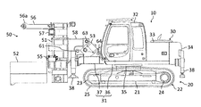
図1は本発明の一実施形態に係る杭打機の全体構成を表す側面図である。本実施形態において、同図中における左右を杭打機の前後、紙面に直交する方向の手前側及び奥側を杭打機の左右とする。図1に示した杭打機は油圧ショベルをベースマシンとするものであり、車体10及び杭打作業機50を備えている。車体10は、走行体20及び旋回体30を備えている。
1. Pile driver FIG. 1 is a side view showing the overall configuration of a pile driver according to an embodiment of the present invention. In the present embodiment, the left and right in the figure are the front and rear of the pile driver, and the front and back sides in the direction orthogonal to the paper surface are the left and right of the pile driver. The pile driver shown in FIG. 1 uses a hydraulic excavator as a base machine and includes a
走行体20は、トラックフレーム21及び左右一対のクローラ22を備えている。左右のクローラ22は、トラックフレーム21の前後に取り付けた従動輪23及び駆動輪(不図示)と、これら従動輪23及び駆動輪に掛け回した履帯25とをそれぞれ備えている。駆動輪には油圧モータ等の走行駆動装置24が連結され、走行駆動装置によりクローラ22を駆動することで杭打機が走行する。走行駆動装置24は駆動輪に出力軸が連結されたモータ及び減速機からなる。なお、走行体20はクローラ式ではなくホイール式であっても良い。
The
旋回体30は、走行体20の上部に旋回に設けた杭打機の本体であり、旋回フレーム31、運転室32、動力室33及びカウンタウェイト34を備えている。旋回フレーム31は旋回体30のベースフレームであり、フレーム本体36及びフロントフレーム37を含んでいる。フレーム本体36は、走行体20のトラックフレーム21上に旋回装置35を介して連結されている。運転室32、動力室33及びカウンタウェイト34は、フレーム本体36の上部に前側からその順に搭載されている。動力室33には、エンジンや油圧駆動装置等が収容されている。上記の旋回装置35には油圧モータ等の旋回モータ(不図示)が設けられており、旋回モータによって走行体20に対して旋回体30が旋回駆動される。フロントフレーム37は、フレーム本体36に連結されてフレーム本体36の前方に延在している。フロントフレーム37の左右の前端部、及びフレーム本体36の左右の後端部には、アウトリガー38が支持されている。
The revolving
杭打作業機50は、旋回フレーム31に連結されたリーダ51、リーダ51に支持された打設装置52、リーダ51の姿勢を固定するリンク53を含んでいる。リンク53は、後述するアタッチメント75、揚重機70、ストッパ68等と共に杭打機の姿勢変更装置を構成する。リーダを前後に傾斜させるために一般的な杭打機に備わっているバックステーシリンダは、リーダ51の上端の後部にスペースを確保するためにあえて省略してある。杭打作業時のリーダ51の角度については、4本のアウトリガー38を接地させ、それらの伸縮量を調整して車体の角度を前後左右に傾けることで調整できる。従って、リーダを左右に傾斜させるために一般的な杭打機に備わっているスイングシリンダも省略してある。
The
本実施形態で例示する打設装置52は、杭(例えば鋼管)の外周部を把持し、把持した杭を回転させて地面に圧入することで杭を打設する回転圧入式である。但し、スクリュー(オーガ)を回転させて地面を掘削するもののように他のタイプの打設装置を採用する場合もある。この打設装置52はリーダ51に対して昇降自在に支持されていて、駆動装置(不図示)によってリーダ51に沿って昇降する。
The driving
リーダ51は、打設装置52を昇降可能に支持する支柱状の部材であり、図1のように起立した作業姿勢では上下(同図では鉛直)に延びる。本実施形態ではリーダ51の上下方向の中央部よりやや下寄りの位置にウィンチ55が、上端部にウィンチアーム56が設けられている。リーダ51は短尺であり、起立時にはウィンチアーム56を含めて上端部が運転室32の上端よりも低くなるように長さが設定されている。ウィンチアーム56の先端部には、ウィンチ55のワイヤロープ(不図示)を掛けるための滑車(不図示)が設けられている。ウィンチアーム56を前方に延ばした状態では、図1に示したように滑車を収容した部分56aがウィンチアーム56の他の部分よりも若干上側に突出している。ウィンチ55は杭や後述するアタッチメント75(図4等)等を吊り上げるために上記の滑車を介してウィンチアーム56から垂下するワイヤロープの巻取り及び繰出しをするものである。またウィンチアーム56はリーダ51に設けた軸受57によって上下(作業姿勢時のリーダ51の中心線と平行)に延びる軸を中心にして水平方向に旋回する。前述した通りバックステーシリンダを省略したことで、軸受57から運転室32まで真直ぐ後方に延ばした線上に構成要素がない。これによりウィンチアーム56は、図1のように前方に延びる姿勢から後方に延びる姿勢(図7等)まで旋回する構成である。具体的には、図7のように後方に指し示した状態を3時の方向として時計に例えると、ウィンチアーム56は3時の方向から11時の方向まで時計回りに旋回できる。これにより、リーダ51が後述する走行姿勢とのきにウィンチアーム56を後方に延びる姿勢にすると(図15等)、ウィンチアーム56の先端の滑車(滑車を収容する部分56a)がウィンチアームの基部よりも低くなるようになっている。この状態ではウィンチアーム56の基部が杭打作業機50の上端となるが、本実施形態ではその高さは運転室32の上端と同程度である。また、杭打機を運搬車両に積載した場合、走行姿勢のままでも一般道路の輸送制限高さに納まるようになっている。
The
図2は図1に示した杭打機のリーダと旋回フレームとの連結部を抜き出して示した側面図である。リーダ51は後部にブラケット58を備えている。このリーダ51のブラケット58は、旋回フレーム31のフロントフレーム37の上部に備わったブラケット59に対し、左右に延びる軸61を介して回動自在に連結されている。またブラケット58の後部にはピン孔62が設けられている。このピン孔62はリンクピン63を挿入するための孔である。このとき、上記のリンク53は、旋回フレーム31のフロントフレーム37の上部に設けられたブラケット60に対し、左右に延びる軸64を介して基端が回動可能に連結されている。軸64は、ブラケット58のピン孔62の回転軌跡の後縁部よりもやや後方に位置する。リンク53にはストッパ68が設けられており、リンク53が回動する角度範囲がストッパ68により規制されている。図2に示した角度からリンク53が後傾すると、鉛直に起立したところで図3に示したようにストッパ68がブラケット60に当たり、リンク53の重心がリンク53の回動支点(軸64の中心)よりも揚重機70に近い側に移動しないように構成してある。
FIG. 2 is a side view showing a connection portion between the leader and the turning frame of the pile driver shown in FIG. The
リンク53には同径のピン孔65,66(ピン孔65は図3参照)が設けられている。第1のピン孔65はリンク53の先端近傍に、第2のピン孔66はリンク53の前部に突出したブラケット67に設けられている。軸64から第1のピン孔65までの距離L1は、軸64から第2のピン孔66までの距離L2よりも長く設定されている。ピン孔62,65にリンクピン63を挿し込んだ状態では、リーダ51が起立した(上下に延びる)作業姿勢で旋回フレーム31に固定されるように、上記距離L1が設定されている。ピン孔62,66にリンクピン63を挿し込んだ状態(図15等)では、リーダ51が後傾した走行姿勢で旋回フレーム31に固定される。走行姿勢においては、走行体20の接地部の前端とリーダ51の下端を結ぶ線が地面(例えば水平面)との間になす角度θ(図15)つまりデパーチャアングルが例えば15度程度となるように、リンク53の上記距離L2が構成されている。
The
また、旋回フレーム31の前部(つまりフロントフレーム37)には、リンク53よりも後側の部分にポスト69が設けられている。このポストには揚重機70が支持されている。揚重機70はリンク53の角度調整用に備え付けられた人力駆動式のもので、揚重機70のチェーンがリンク53の後部に設けたブラケット71に掛けられるようになっている。ブラケット71にチェーンを掛け、揚重機70を操作してチェーンを巻き上げたり繰り出したりすることでリンク53が起伏するようになっている。
Further, a
2.アタッチメント
図4は本発明の一実施形態に係る杭打機に備えられたアタッチメントの側面図、図5は正面図である。本実施形態に係る杭打機の姿勢変更システムは、図1等で説明した杭打機と図4等に示したアタッチメント75を含み、前述した作業姿勢から走行姿勢に、また走行姿勢から作業姿勢に、アタッチメント75を補助的に用いて杭打機の姿勢を変更するものである。アタッチメント75は上部パーツ76と下部パーツ77に分割可能に構成されている。上部パーツ76はアタッチメント75を打設装置52で把持するためのパーツであり、例えば打設装置52で把持する杭と同程度の外径を持つ円筒状の形状をしている。上部パーツ76の上下方向の寸法は、リーダ51の下部まで下げた打設装置52とウィンチアーム56との間に納まる程度である。上部パーツ76の内側の空間には水平方向にパイプ78が渡されており、パイプ78は上部パーツ76の外周面に開口している。パイプ78にはウィンチ55のワイヤ又はワイヤを掛けるための治具(不図示)を通すことができ、打設装置52を下げて上部パーツ76をウィンチ55で吊り上げることで、打設装置52の内部に上部パーツ76を挿入できるように構成されている。下部パーツ77は、下端部に左右一対の車輪79を有している。下部パーツ77は高さ寸法は上部パーツ76と同程度であるものの、上部パーツ76に比べて小径で軽量に構成されている。これら上部パーツ76と下部パーツ77が複数のピン80で連結され、下端に車輪79を有し上部が打設装置52で把持可能な一体のアタッチメント75となる。
2. Attachment FIG. 4 is a side view of the attachment provided in the pile driver according to the embodiment of the present invention, and FIG. 5 is a front view. The attitude changing system for a pile driver according to the present embodiment includes the pile driver described with reference to FIG. 1 and the like and the
3.姿勢変更方法
本実施形態に係る杭打機は、例えば仮設の基礎工事現場が内部にある商業施設から離れたところで待機しており、商業施設(例えば交通機関)の営業終了時刻に合わせてトレーラ等の輸送車両で搬送されてくる。輸送車両には自走して乗降するため、この時点では杭打機は走行姿勢である。図6に示したように、商業施設Xに到着した杭打機は輸送車両から自走して降り、例えば施設利用客が通行する歩行者用通路等の移動経路Yを走行して移動する。杭打機を走行させる際には、商業施設内の床を傷めないように杭打機の走行経路に敷物をする。移動経路Yは天井や天井から吊り下がる案内看板等で走行姿勢の杭打機の全高を厳しく制約する。移動経路Yの途中にはスロープSが存在する場合もある。移動経路Yを走行して商業施設Xに設けられた基礎工事現場Zに到着したら、杭打機の姿勢を作業姿勢に変更する。走行姿勢から作業姿勢への姿勢変更手順は、後で説明する作業姿勢から走行姿勢への姿勢変更手順と反対の手順である。杭打機を作業姿勢にしたら、機体の四隅のアウトリガー38を接地させてリーダ51の角度を鉛直に調整し、ウィンチ55や打設装置52を用いて杭打作業を施工する。基礎工事現場Zも移動経路Yと同じく商業施設の天井等で高さが制約され、杭打作業も高さに制約がある中で行われる。この杭打作業は、再度杭打機を走行姿勢にして移動経路Yを通って商業施設Xの外まで走行するのに要する時間等を考慮して、商業施設の営業開始時刻から逆算した時刻まで行われる。
3. Posture Change Method The pile driving machine according to the present embodiment is on standby, for example, at a place where a temporary foundation construction site is away from an internal commercial facility, and a trailer or the like is set according to the closing time of the commercial facility (for example, transportation). Will be transported by the transport vehicle. At this point, the pile driver is in the running posture because the transport vehicle is self-propelled and gets on and off. As shown in FIG. 6, the pile driver arriving at the commercial facility X travels on its own from the transport vehicle and then travels along the travel route Y such as a pedestrian passage through which facility users pass. When driving the pile driver, a rug is placed on the route of the pile driver so as not to damage the floor in the commercial facility. The movement route Y is a ceiling or a signboard hanging from the ceiling, and severely restricts the overall height of the pile driver in the traveling posture. There may be a slope S in the middle of the movement route Y. When the vehicle travels along the moving route Y and arrives at the foundation construction site Z provided in the commercial facility X, the posture of the pile driver is changed to the working posture. The procedure for changing the posture from the running posture to the working posture is the reverse of the procedure for changing the posture from the working posture to the running posture described later. After the pile driver is in the working posture, the
図7〜図15を用いて本実施形態に係る杭打機の作業姿勢から走行姿勢への姿勢変更方法を説明する。なお、図10及び図12においては、揚重機70が見えるように運転室32や動力室33、カウンタウェイト34を図示省略している。
A method for changing the attitude of the pile driver according to the present embodiment from the working attitude to the running attitude will be described with reference to FIGS. 7 to 15. 10 and 12, the driver's
基礎工事現場Zにおいて杭打作業の制限時刻が到来したら杭打作業を中止し、移動経路Yを走行して基礎工事現場Zから退去すべく、杭打機の姿勢を作業姿勢から走行姿勢に変更する。その際、まず図7に示したように人力でウィンチアーム56を後向きに反転させ、杭打作業開始前の使用後に左右の走行体20の間のスペースに下しておいたアタッチメント75の上部パーツ76にワイヤロープを掛ける。次に図8に示したように、ウィンチ55で上部パーツ76を吊り上げ、人力でウィンチアーム56を前方に回動させて、上部パーツ76を打設装置52の中に吊り下しつつ打設装置52を上昇させる。このとき、上部パーツ76を打設装置52に上から通せるように、打設装置52は予め所定の高さまで下降させておく。
At the foundation construction site Z, when the time limit for the pile driving work arrives, the pile driving work is stopped, and the posture of the pile driving machine is changed from the work posture to the traveling posture so that the pile driving work is moved along the moving route Y to leave the foundation construction site Z. To do. At this time, first, as shown in FIG. 7, the
続いて車輪79を利用して例えば人力で下部パーツ77を上部パーツ76の下側まで運搬し、必要に応じて打設装置52を駆動させて上部パーツ76と下部パーツ77の位置合わせをして、図9に示したように両者を連結する。上部パーツ76と下部パーツ77を連結したら、車輪79の走行方向が前後方向となるようにアタッチメント75の向きを調整した上で上部パーツ76を打設装置52で把持する。その後図10に示したように揚重機70のチェーンをリンク53に掛け、リンクピン63を抜き取ってリンク53とリーダ51との連結を解き、揚重機70を操作して図11及び図12に示したようにリンク53を後方に回動させて起立させる。また打設装置52で上部パーツ76が把持できたら、リンクピン63の抜き取りと前後して上部パーツ76からワイヤロープを外し、ウィンチアーム56を後向きに反転させておく。
Then, using the
リンク53とリーダ51との連結解除後、リーダ51に対して打設装置52を下降させる。アタッチメント75が接地しているので、打設装置52の下降に伴ってアタッチメント75の車輪79を地面に転動させながら、図13に示したようにリーダ51は後傾していく。他方、リーダ51の角度を調整しつつ、揚重機70でリンク53の角度を調整し、リンク53の第2のピン孔66(図12)とリーダ51のピン孔62(図13)と位置を合わせて、図14に示したようにピン孔62,66にリンクピン63を挿し込む。これによりリンク53により走行姿勢でリーダ51が固定される。最後に、図15に示したように打設装置52からアタッチメント75を取り外し、必要に応じて重心を下げるために打設装置52を下降させ、走行姿勢への姿勢変更作業が完了する。アタッチメント75の取り外しについては、例えばウィンチ55やジャッキ付きの台車(不図示)等でアタッチメント75を支持しながら打設装置52のチャックを緩めて行うことができる。
After releasing the connection between the
4.効果
(1)高さ制限下での運用性
本実施形態によれば、リーダ51が短尺でリーダ51の上端が運転室32の上端よりも低いので商業施設X等の建物内部で天井等により高さが制限された基礎工事現場Zであっても杭打作業を施工することができる。また、下端に車輪79を有するアタッチメント75を打設装置52で把持し、リンクピン63を外しリンク53とリーダ51の拘束を解いて打設装置52を下降させることで、バックステーシリンダがなくても自力でリーダ51を後傾させることができる。これにより高さが制限された空間内でも効率的に作業姿勢から走行姿勢への姿勢変更ができ、デパーチャアングルを確保してスロープSを移動したり輸送車両に自走して乗降したりすることができる。高さ制限下で走行姿勢から作業姿勢への姿勢変更も容易である。よって、天井で高さが制限された空間内で走行、杭打ち作業及びリーダ51の姿勢変更をし、空間的及び時間的な大きな制約下で効率的に杭打ち作業を行うことができる。
4. Effect (1) Operability under height restriction According to the present embodiment, since the
また、杭打機を運搬車両に積載し走行姿勢のままにしておいても一般道路の輸送制限高さに納めることができ、一般道路を輸送する際に運搬車両の荷台上で作業姿勢に姿勢変更をする必要がない。よって次回の作業の際に輸送車両から降車するに当たって姿勢変更をする必要がなく、商業施設Xに到着した後の移動走行の準備時間が抑えられ、この点でも限られた時間で効率的に作業を進捗させることができる。 In addition, even if the pile driver is loaded on the transport vehicle and kept in the running posture, it can be placed within the transport height limit on the general road, and when transporting on the general road, the posture is set to the work posture on the carrier bed No need to change. Therefore, at the time of the next work, it is not necessary to change the posture when getting off the transport vehicle, and the preparation time for traveling after arriving at the commercial facility X can be suppressed, and in this respect as well, work can be performed efficiently in a limited time. Can be progressed.
また運転室32を備えオペレータが機体に乗り込んで操作できるので、例えば杭打機を無線操作式として、狭い移動経路の中で杭打機の傍に立ってこれを操作するよりも操作性が良い。
Further, since the operator is provided with the driver's
(2)姿勢変更作業の効率化
仮に作業姿勢でリーダ51を固定するための第1リンクと走行姿勢でリーダ51を固定するための第2リンクを別々に用意した場合、杭打機の姿勢変更の度にリンク交換の作業をしなければならない。それに対し、軸64からの距離が異なる2つのピン孔65,66をリンク53に設けたことにより、1本のリンク53によって作業姿勢又は走行姿勢でリーダ51を選択的に固定することができる。これにより姿勢変更作業がより効率的に行える。外したリンクの保管を考慮する必要もない。但し、本質的な上記効果(1)を得る限りにおいては、一体のリンク53ではなく、作業姿勢時と走行姿勢時で別々の第1リンク及び第2リンクを用いる構成としても良い。
(2) Efficiency improvement of posture change work If the first link for fixing the
更に、本実施形態では旋回フレーム31にポスト69を設けて揚重機70を設置したので、これもリンク53の角度調整の容易化ひいては姿勢変更作業の向上に貢献する。特に揚重機70は人力駆動式であるので動力式のものに比べて操作量の微調整が容易である。また動力が不要である点もメリットである。但し、上記効果(1)を得る限りにおいては、揚重機70を車載する必要は必ずしもない。
Further, in the present embodiment, the
また本実施形態の場合、重心が軸64の中心よりも揚重機70に近付かないようにリンク53の回動範囲をストッパ68で制限した。これにより、揚重機70の操作量に依らず、リンク53が揚重機70側に倒れて揚重機70による角度調整が不能な状態になることがない。この点も姿勢変更作業の効率向上に貢献する。但し、上記効果(1)を得る限りにおいては、ストッパ68も必ずしも必要ない。
Further, in the case of this embodiment, the rotation range of the
(3)走行姿勢の全高低減
リーダ51には前部に打設装置52が取り付けられているため、リーダ51を後に90度倒して水平に寝かせてしまうと、打設装置52が上に延びる格好となって走行姿勢時の機体全高が高くなってしまう。姿勢変更の過程では更に機体全高が高くなる瞬間がある。従って、走行姿勢時及び姿勢変更時に打設装置52の一部がリーダ51の上端よりも高くなることがないように、本実施形態ではデパーチャアングルが確保できる程度にリーダ51を後傾させた姿勢を走行姿勢としている。その際、例えば基礎工事現場Z又は移動経路Yが駅コンコース等であれば、天井から吊り下がる案内看板と運転室32との間隔は非常に狭く、人間の頭が入るか入らないか程度である。従って後傾した杭打作業機50の上端の高さは少しでも低くしたい。
(3) Reduction in overall height of running posture Since the placing
本実施形態ではウィンチアーム56の先端にはワイヤロープを掛ける滑車を収容した部分56aがあり、これがウィンチアーム56の他の部分に対して高くなっている。この場合、仮にリーダ51の後部にバックステーシリンダを取り付けたら、バックステーシリンダが邪魔してウィンチアーム56を後向きに反転させることができない。そこで一般的な杭打機と同じくウィンチアーム56を左右に延ばした状態でリーダ51を後傾させデパーチャアングルを確保しようとすると、滑車を収容した部分56aがウィンチアーム56の他の部分に対して高い分だけ走行姿勢時の機体全高が高くなってしまう。
In this embodiment, the
そこで本実施形態ではあえてバックステーシリンダは採用せず、上記の通りバックステーシリンダに依らないリーダ51の自力傾斜を可能としたことで、リーダ51の後側に運転室32との間に構造物のないスペースを創出している。このスペースを利用することにより、ウィンチアーム56を後向きに反転させることができる。ウィンチアーム56を後向きにした状態でリーダ51を後傾させると、図15に示したように滑車を収容した部分56aがウィンチアーム56の他の部分に対して低くなる。これによりバックステーシリンダを採用してウィンチアーム56の旋回範囲を90度に制限せざるを得ない構成に比べて、走行姿勢時の機体全高を低くすることができる。但し、上記効果(1)を得る限りにおいては、必ずしもウィンチアーム56を後向きに反転させられる構造でなくても良い。
Therefore, in the present embodiment, the backstay cylinder is not used, and the
(4)実用性
リーダ51が短尺であるため、下限まで下げた打設装置52とウィンチアーム56との間の間隔が短く、アタッチメント75を一体に構成するとウィンチ55を使ってアタッチメント75を打設装置52にセットできない可能性がある。一体の場合はアタッチメント75の重量も増すので、人手による運搬も容易ではなくなる。
(4) Practicality Since the
それに対し、本実施形態ではアタッチメント75を上部パーツ76と下部パーツ77の2分割構造としたので、パーツ単位では高さ寸法が抑えられ、車載設備であるウィンチ55を使って上部パーツ76を打設装置52に挿入することができる。また下部パーツ77はアタッチメント75の全体重量の半分にも満たないので軽量であり、車輪79を備えていることから人手による移動も可能である。従って「3.姿勢変更方法」の欄で先に説明した手順で、アタッチメント75を打設装置52に容易にセットすることができる。また、アタッチメント75を用いてリーダ51を構成させた後、アタッチメント75を分解して下部パーツ77を取り外せば、上部パーツ76を打設装置52でチャックしたままでもデパーチャアングルを確保することができる。但し、上記効果(1)を得る限りにおいては、アタッチメント75が分割構造である必要は必ずしもない。
On the other hand, in this embodiment, since the
20…走行体、30…旋回体、31…旋回フレーム、32…運転室、50…杭打作業機、51…リーダ、52…打設装置、53…リンク(第1リンク、第2リンク、一体のリンク)、55…ウィンチ、56…ウィンチアーム、56a…滑車を収容した部分、61…軸、68…ストッパ、69…ポスト、70…揚重機、75…アタッチメント、76…上部パーツ、77…下部パーツ、79…車輪 20... Running body, 30... Revolving structure, 31... Revolving frame, 32... Driver's cab, 50... Pile driving machine, 51... Leader, 52... Placing device, 53... Link (1st link, 2nd link, integrated) Link), 55... winch, 56... winch arm, 56a... portion accommodating pulley, 61... shaft, 68... stopper, 69... post, 70... lifting machine, 75... attachment, 76... upper part, 77... lower part Parts, 79... Wheels
Claims (5)
前記リーダが、前記作業姿勢で上端が前記運転室の上端よりも低くなるように長さが設定されており、
前記姿勢変更装置は、
前記作業姿勢の前記リーダを前記旋回フレームに連結する第1リンクと、
前記走行姿勢の前記リーダを前記旋回フレームに連結する第2リンクと、
下端に車輪を有し前記打設装置で把持可能なアタッチメントとを備えており、
前記姿勢変更装置を構成する前記第1リンク及び前記第2リンクを一体のリンクとして形成し、
前記旋回フレームの前部にポストを設けており、
前記姿勢変更装置は、前記ポストに支持された前記一体のリンクの角度調整用の揚重機を備えていることを特徴とする杭打機。 A traveling structure, a revolving structure having a driver's cab provided above the traveling structure, and a pile driving machine connected to a revolving frame that is a base frame of the revolving structure, and the pile driving machine is provided on the left and right. A leader that is rotatably connected to the swivel frame via an extending shaft, a placing device that moves up and down along the leader, a winch that is provided on the leader, and a pulley that is provided above the leader and hangs a wire on the tip. In a pile driver equipped with a winch arm having a posture changing device for changing the posture from a working posture in which the leader stands up to a traveling posture in which the leader tilts backward, and from the traveling posture to the working posture,
The leader, the length is set so that the upper end is lower than the upper end of the cab in the work posture,
The posture changing device,
A first link connecting the leader in the working position to the swivel frame;
A second link connecting the leader in the running posture to the swing frame;
With an attachment that has wheels at the lower end and can be gripped by the driving device,
The first link and the second link that constitute the posture changing device are formed as an integral link,
A post is provided at the front of the revolving frame,
The posture changing device includes a lifting machine for adjusting an angle of the integrated link supported by the post.
前記リーダが、前記作業姿勢で上端が前記運転室の上端よりも低くなるように長さが設定されており、
前記姿勢変更装置は、
前記作業姿勢の前記リーダを前記旋回フレームに連結する第1リンクと、 前記走行姿勢の前記リーダを前記旋回フレームに連結する第2リンクと、
下端に車輪を有し前記打設装置で把持可能なアタッチメントとを備えており、
前記姿勢変更装置を構成する前記第1リンク及び前記第2リンクを一体のリンクとして形成し、
前記旋回フレームの前部にポストを設けており、
前記姿勢変更装置は、前記ポストに支持された前記一体のリンクの角度調整用の揚重機を備えている杭打機の姿勢変更方法において、
前記作業姿勢で前記アタッチメントを吊り上げて前記打設装置で把持する工程と、
前記一体のリンクと前記リーダとの連結を解いて前記リーダに対して前記打設装置を下降させて前記リーダを後傾させる工程と、
前記揚重機で前記一体のリンクの角度を調整する工程と、
前記一体のリンクにより前記走行姿勢で前記リーダを固定する工程と、
前記打設装置から前記アタッチメントを取り外す工程とからなることを特徴とする杭打機の姿勢変更方法。 A traveling structure, a revolving structure having a driver's cab provided above the traveling structure, and a pile driving machine connected to a revolving frame that is a base frame of the revolving structure, and the pile driving machine is provided on the left and right. A leader that is rotatably connected to the swivel frame via an extending shaft, a placing device that moves up and down along the leader, a winch that is provided on the leader, and a pulley that is provided above the leader and hangs a wire on the tip. A pile driving machine including a winch arm having a posture change device for changing the posture from a working posture in which the leader stands up to a traveling posture in which the leader leans backward and from the traveling posture to the working posture. hand,
The leader, the length is set so that the upper end is lower than the upper end of the cab in the work posture,
The posture changing device,
A first link connecting the leader in the working posture to the swing frame; a second link connecting the leader in the running posture to the swing frame;
With an attachment that has wheels at the lower end and can be gripped by the driving device,
The first link and the second link that constitute the posture changing device are formed as an integral link,
A post is provided at the front of the revolving frame,
The posture changing device is a posture changing method for a pile driver, comprising a lifting machine for adjusting the angle of the integral link supported by the post,
Lifting the attachment in the work posture and gripping it with the placing device;
Releasing the connection between the integrated link and the leader to lower the placing device with respect to the leader to tilt the leader backward;
Adjusting the angle of the integral link with the hoist,
Fixing the reader in the running posture by the integral link;
A method of changing the attitude of a pile driving machine, comprising the step of removing the attachment from the driving device.
Priority Applications (1)
| Application Number | Priority Date | Filing Date | Title |
|---|---|---|---|
| JP2017163715A JP6738779B2 (en) | 2017-08-28 | 2017-08-28 | Pile driver and method of changing the posture of the pile driver |
Applications Claiming Priority (1)
| Application Number | Priority Date | Filing Date | Title |
|---|---|---|---|
| JP2017163715A JP6738779B2 (en) | 2017-08-28 | 2017-08-28 | Pile driver and method of changing the posture of the pile driver |
Publications (3)
| Publication Number | Publication Date |
|---|---|
| JP2019039266A JP2019039266A (en) | 2019-03-14 |
| JP2019039266A5 JP2019039266A5 (en) | 2019-07-11 |
| JP6738779B2 true JP6738779B2 (en) | 2020-08-12 |
Family
ID=65726952
Family Applications (1)
| Application Number | Title | Priority Date | Filing Date |
|---|---|---|---|
| JP2017163715A Active JP6738779B2 (en) | 2017-08-28 | 2017-08-28 | Pile driver and method of changing the posture of the pile driver |
Country Status (1)
| Country | Link |
|---|---|
| JP (1) | JP6738779B2 (en) |
Family Cites Families (12)
| Publication number | Priority date | Publication date | Assignee | Title |
|---|---|---|---|---|
| JPH0738374Y2 (en) * | 1988-12-23 | 1995-08-30 | 日立建機株式会社 | Pile driver |
| EP0902128A3 (en) * | 1997-09-11 | 1999-04-28 | Van Splunder Funderingstechniek B.V. | Method for installing a foundation for a traffic course as well as device |
| JP2002242578A (en) * | 2001-02-21 | 2002-08-28 | Nippon Sharyo Seizo Kaisha Ltd | Leader storage device for pile driver |
| JP3745674B2 (en) * | 2001-10-26 | 2006-02-15 | コベルコ建機株式会社 | Attachment storage device for construction machine work |
| JP4931478B2 (en) * | 2006-06-01 | 2012-05-16 | 日立建機株式会社 | Low head pile driver |
| JP4642056B2 (en) * | 2007-10-11 | 2011-03-02 | 日立建機株式会社 | Calibration device for torque measuring instrument of pile driving attachment |
| JP5562051B2 (en) * | 2010-01-28 | 2014-07-30 | 日本車輌製造株式会社 | Pile driver |
| JP5988858B2 (en) * | 2012-12-18 | 2016-09-07 | 日本車輌製造株式会社 | Pile driver |
| JP2015229867A (en) * | 2014-06-05 | 2015-12-21 | 日立建機株式会社 | Pile driver |
| JP6472224B2 (en) * | 2014-11-26 | 2019-02-20 | 日本車輌製造株式会社 | Pile driver lower leader attachment / detachment jig |
| JP6504836B2 (en) * | 2015-01-29 | 2019-04-24 | 日本車輌製造株式会社 | Pile driving machine |
| JP6360004B2 (en) * | 2015-06-04 | 2018-07-18 | 日立建機株式会社 | Pile driver |
-
2017
- 2017-08-28 JP JP2017163715A patent/JP6738779B2/en active Active
Also Published As
| Publication number | Publication date |
|---|---|
| JP2019039266A (en) | 2019-03-14 |
Similar Documents
| Publication | Publication Date | Title |
|---|---|---|
| JP2004243805A (en) | Transporting method and transporter of irregular shaped elongated article | |
| JP4455828B2 (en) | Crane with self-lifting mast | |
| JPH10500462A (en) | Mounting method and device for lightweight panel unit | |
| JP2007112526A (en) | Self-traveling type small sized crane | |
| KR20190031213A (en) | High place working vehicles having tiltable basket | |
| JP6738779B2 (en) | Pile driver and method of changing the posture of the pile driver | |
| JP2017103995A (en) | Supporting device for work vehicle | |
| JP3977073B2 (en) | Rotary press machine | |
| JP4922780B2 (en) | Crane and disassembling method of crane | |
| WO2016154722A1 (en) | Mobile drilling system | |
| JP5121408B2 (en) | Structure loading / unloading device to be attached to / detached from the jack of work equipment with jack | |
| TWI740251B (en) | Low-headroom excavator and assembly method thereof | |
| CN113481972A (en) | Steel reinforcement cage material loading transportation and lower cage device | |
| JP2004175545A (en) | Bridge crane | |
| JP5012591B2 (en) | Tube transport vehicle | |
| JPH09268557A (en) | Pile driving/drawing device | |
| JPH08259177A (en) | Handling device of pipe | |
| JP5248448B2 (en) | Support device for transport of upper swing body and transport method of upper swing body | |
| JPH11100191A (en) | Jack-up device of construction machine and turning method for jack-up cylinder | |
| JP4236761B2 (en) | Pipe-type carriage for transporting pipes | |
| JP2002226176A (en) | Crawler crane | |
| JP2001207770A (en) | Transporting installing device and transporting installing method for steel pipe press-in device | |
| CN215057498U (en) | Vehicle-mounted anchor rod trolley | |
| JP2006125032A (en) | Pile construction machine | |
| JP6897974B2 (en) | Pile driving device |
Legal Events
| Date | Code | Title | Description |
|---|---|---|---|
| A521 | Written amendment |
Free format text: JAPANESE INTERMEDIATE CODE: A523 Effective date: 20190523 |
|
| A621 | Written request for application examination |
Free format text: JAPANESE INTERMEDIATE CODE: A621 Effective date: 20190523 |
|
| A977 | Report on retrieval |
Free format text: JAPANESE INTERMEDIATE CODE: A971007 Effective date: 20200629 |
|
| TRDD | Decision of grant or rejection written | ||
| A01 | Written decision to grant a patent or to grant a registration (utility model) |
Free format text: JAPANESE INTERMEDIATE CODE: A01 Effective date: 20200707 |
|
| A61 | First payment of annual fees (during grant procedure) |
Free format text: JAPANESE INTERMEDIATE CODE: A61 Effective date: 20200720 |
|
| R150 | Certificate of patent or registration of utility model |
Ref document number: 6738779 Country of ref document: JP Free format text: JAPANESE INTERMEDIATE CODE: R150 |