JP6726513B2 - Electric reel motor controller - Google Patents
Electric reel motor controller Download PDFInfo
- Publication number
- JP6726513B2 JP6726513B2 JP2016083319A JP2016083319A JP6726513B2 JP 6726513 B2 JP6726513 B2 JP 6726513B2 JP 2016083319 A JP2016083319 A JP 2016083319A JP 2016083319 A JP2016083319 A JP 2016083319A JP 6726513 B2 JP6726513 B2 JP 6726513B2
- Authority
- JP
- Japan
- Prior art keywords
- output
- motor
- pressing force
- reel
- motor control
- Prior art date
- Legal status (The legal status is an assumption and is not a legal conclusion. Google has not performed a legal analysis and makes no representation as to the accuracy of the status listed.)
- Active
Links
Images


Classifications
-
- A—HUMAN NECESSITIES
- A01—AGRICULTURE; FORESTRY; ANIMAL HUSBANDRY; HUNTING; TRAPPING; FISHING
- A01K—ANIMAL HUSBANDRY; CARE OF BIRDS, FISHES, INSECTS; FISHING; REARING OR BREEDING ANIMALS, NOT OTHERWISE PROVIDED FOR; NEW BREEDS OF ANIMALS
- A01K89/00—Reels
- A01K89/015—Reels with a rotary drum, i.e. with a rotating spool
- A01K89/017—Reels with a rotary drum, i.e. with a rotating spool motor-driven
Description
本発明は、モータ制御装置、特に、電動リールのリール本体に装着されたスプールを回転させるモータを制御するためのモータ制御装置に関する。 The present invention relates to a motor control device, and more particularly to a motor control device for controlling a motor that rotates a spool mounted on a reel body of an electric reel.
一般に、釣り糸巻き上げ時のスプール回転をモータで行う電動リールは、リール本体と、リール本体に装着されたスプールと、スプールを回転させるハンドルと、スプールを巻き上げ方向に回転させるモータと、を備えている。スプールの巻き上げ速度を変更するための操作部に、圧力センサを用いたものや(特許文献1)、リール本体の側部前方に揺動自在のレバー部材を設けたものがよく知られている。 Generally, an electric reel in which a motor rotates a spool when winding a fishing line includes a reel body, a spool mounted on the reel body, a handle for rotating the spool, and a motor for rotating the spool in a winding direction. .. It is well known that an operation unit for changing the winding speed of the spool uses a pressure sensor, or one in which a swingable lever member is provided in front of a side portion of the reel body.
また、しゃくり動作などを容易に行うための寸動スイッチ等の操作部材を、レバー部材の操作部材とは別に設けたものがよく知られている。例えば、寸動スイッチは、寸動スイッチが押圧操作されている間だけ、所定速度でモータを回転させて釣り糸が巻き上げられる。 Further, it is well known that an operating member such as an inching switch for easily performing the hiccup operation is provided separately from the operating member of the lever member. For example, the inching switch winds the fishing line by rotating the motor at a predetermined speed only while the inching switch is being pressed.
特許文献1の操作部材は、押圧力の強弱によって、圧力センサの出力を変化させて、その出力に応じてスプールの巻き上げ速度の変更を行うが、人間の押圧力には個人差がある。また、寒い環境下では押圧力が弱まる可能性があり、押圧力は電動リールを操作する環境にも左右されやすい。押圧力が不足すると、モータ出力を迅速かつ容易に調節することが難しくなる。
The operation member of
本発明の課題は、電動リールにおいて、操作環境や押圧条件によってモータ出力がばらつくのを抑え、モータ出力を迅速かつ容易に調節できるようにすることにある。 SUMMARY OF THE INVENTION An object of the present invention is to suppress variations in motor output due to operating environment and pressing conditions in an electric reel so that the motor output can be adjusted quickly and easily.
本発明の一側面に係る電動リールのモータ制御装置は、リール本体に回転自在に装着されたスプールをモータで駆動する電動リールのモータ制御装置であって、押圧操作部と、モータ制御手段と、出力調整手段と、を備えている。押圧操作部は、押圧力に応じて出力が変化する圧力センサを有し、リール本体に設けられている。モータ制御手段は、圧力センサの出力に応じてモータ出力を制御する。出力調整手段は、圧力センサにおける押圧力の最大値の閾値を任意に設定する。 An electric reel motor control device according to one aspect of the present invention is an electric reel motor control device that drives a spool, which is rotatably mounted on a reel body, by a motor, and includes a pressing operation portion, a motor control means, and And output adjusting means. The pressing operation unit has a pressure sensor whose output changes according to the pressing force, and is provided on the reel unit. The motor control means controls the motor output according to the output of the pressure sensor. The output adjusting means arbitrarily sets the threshold value of the maximum value of the pressing force in the pressure sensor.
この電動リールのモータ制御装置は、圧力センサにおける押圧力の最大値の閾値を任意に設定することができる。このため、押圧力に応じてモータ出力が変化する場合であっても、押圧力の不足や過剰によるモータ出力のばらつきが生じにくくなり、モータ出力を迅速かつ容易に調節することができる。 The motor control device for the electric reel can arbitrarily set the threshold value of the maximum value of the pressing force in the pressure sensor. Therefore, even when the motor output changes according to the pressing force, variations in the motor output due to insufficient or excessive pressing force are less likely to occur, and the motor output can be adjusted quickly and easily.
好ましくは、出力調整手段は、押圧操作部を複数回押圧したときの押圧力の平均値に基づいて押圧力の最大値の閾値を設定する。この場合は、押圧力に多少のばらつきがあっても、平均値に基づいて押圧力の最大値の閾値を設定するため、押圧力の不足や過剰がより生じにくくなる。 Preferably, the output adjusting means sets the threshold value of the maximum value of the pressing force based on the average value of the pressing force when the pressing operation section is pressed a plurality of times. In this case, the threshold value of the maximum value of the pressing force is set based on the average value even if the pressing force has some variation, so that insufficient or excessive pressing force is less likely to occur.
好ましくは、出力調整手段は、押圧操作部を押圧したときの最大押圧力の所定範囲に基づいて押圧力の最大値の閾値を設定する。 Preferably, the output adjusting means sets the threshold value of the maximum value of the pressing force based on the predetermined range of the maximum pressing force when the pressing operation section is pressed.
好ましくは、出力調整手段は、予め設定された複数の押圧力の値の中から、押圧力の最大値の閾値を設定する。 Preferably, the output adjusting means sets the threshold value of the maximum value of the pressing force from the preset values of the pressing force.
好ましくは、モータ制御手段は、押圧力が大きくなるに従ってモータ出力を大きくする。この場合は、釣り人が押圧操作部を強く押せばモータ出力が大きくなり、釣り人の感覚とモータ出力とが整合するので、モータ出力の調整がより容易になる。 Preferably, the motor control means increases the motor output as the pressing force increases. In this case, if the angler strongly presses the pressing operation portion, the motor output becomes large, and the angler's feeling matches the motor output, so that the motor output can be adjusted more easily.
好ましくは、モータ制御装置は、リール本体に設けられ、前記モータの回転を停止状態から段階的に調整するための出力調整部材をさらに備えている。モータ制御手段は、モータ出力を、出力調整部材の操作によって設定された出力に制御するとともに、出力調整部材の操作によってモータが回転していないとき、圧力センサの出力に応じて制御する。 Preferably, the motor control device further includes an output adjusting member provided on the reel unit and for adjusting the rotation of the motor stepwise from a stopped state. The motor control means controls the motor output to an output set by operating the output adjusting member, and controls the output according to the output of the pressure sensor when the motor is not rotating by operating the output adjusting member.
好ましくは、モータ制御装置は、リール本体に設けられ、モータの回転を停止状態から段階的に調整するための出力調整部材をさらに備えている。モータ制御手段は、モータ出力を、出力調整部材の操作によって設定された出力に制御するとともに、出力調整部材の操作によってモータが回転しているとき、圧力センサの出力に応じて減少させる。 Preferably, the motor control device further includes an output adjusting member that is provided on the reel unit and that adjusts the rotation of the motor stepwise from a stopped state. The motor control means controls the motor output to an output set by operating the output adjusting member, and reduces the output according to the output of the pressure sensor when the motor is rotating by operating the output adjusting member.
好ましくは、出力調整部材は揺動レバーであり、その揺動位置に応じてモータ出力を段階的に調整する。 Preferably, the output adjusting member is a swing lever and adjusts the motor output stepwise according to the swing position.
好ましくは、出力調整部材は、リール本体に回動可能に設けられ、回動位置に応じてモータ出力を段階的に調整する。 Preferably, the output adjusting member is rotatably provided on the reel unit, and adjusts the motor output stepwise according to the rotating position.
好ましくは、押圧操作部は、出力調整部材に一体的に設けられ、出力調整部材の径方向の押圧力に応じて圧力センサの出力が変化する。 Preferably, the pressing operation portion is provided integrally with the output adjusting member, and the output of the pressure sensor changes according to the pressing force of the output adjusting member in the radial direction.
本発明によれば、圧力センサにおける押圧力の最大値の閾値を調整することができるため、押圧力の不足や過剰によるモータ出力のばらつきが生じにくくなり、押圧操作部の押圧によるモータ出力を、迅速かつ容易に調整することができる。 According to the present invention, since it is possible to adjust the threshold value of the maximum value of the pressing force in the pressure sensor, variations in motor output due to insufficient or excessive pressing force are less likely to occur, and the motor output due to the pressing of the pressing operation unit is It can be adjusted quickly and easily.
<第1実施形態>
本発明の第1実施形態を採用した電動リールは、図1に示すように、外部電源から供給された電力によりモータ駆動される電動リールである。また、この電動リールは、糸繰り出し長さ又は糸巻き取り長さに応じて仕掛けの水深を表示する水深表示機能を有する。
<First Embodiment>
The electric reel adopting the first embodiment of the present invention is, as shown in FIG. 1, an electric reel driven by a motor by electric power supplied from an external power source. In addition, this electric reel has a water depth display function for displaying the water depth of the tackle according to the yarn payout length or the yarn winding length.
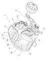
電動リールは、釣竿に装着可能なリール本体1と、リール本体1の内部に配置されたスプール2と、リール本体1の側方に配置されたスプール2の回転用のハンドル3と、ハンドル3のリール本体側に配置されたドラグ調整用のスタードラグ4と、水深表示用のカウンタケース5と、を主に備えている。
The electric reel includes a
リール本体1は、フレーム6と、フレーム6の左右を覆う第1側カバー7a及び第2側カバー7bと、フレーム6の前部を覆う図示しない前カバーと、を有している。また、リール本体1の内部には、スプール2に連動して動作する図示しないレベルワインド機構や、ハンドル3及び後述するモータ8の回転をスプール2に伝達する図示しない回転伝達機構等が設けられている。
The
スプール2は、第1側カバー7aと第2側カバー7bとの間で、リール本体1に回転可能に設けられる。スプール2の内部には、スプール2を糸巻き取り方向に回転駆動するモータ8が配置されている。
The
ハンドル3は、第1側(右側)カバー7aの中央下部に回転自在に支持されている。また、ハンドル3の支持部分の上方前部には、モータ8の出力を複数段階(例えば、10段階以上であり、本実施形態では、31段階)に制御するための出力調整レバー9が揺動自在に支持されている。出力調整レバー9の後方には、クラッチ操作部材10が揺動自在に配置されている。クラッチ操作部材10は、ハンドル3及びモータ8とスプール2との間に設けられた図示しないクラッチをオン、オフ操作するための部材である。
The
カウンタケース5は、リール本体1の前側の上部に配置され、第1側板6a及び第2側板6bに固定されている。カウンタケース5の上面部には、液晶ディスプレイを有する表示部11が設けられている。表示部11の後方側には、図1及び図3に示すように、カウンタケース5から上方向に突出した押圧操作部12と2つの操作スイッチ13と、が配置されている。カウンタケース5の内部には、各種の制御を行う制御部14が収容されている
The
押圧操作部12は、図2に示すように、圧力センサ15を有している。圧力センサ15は、押圧操作部12を押圧する力(以下、押圧力と記す)に応じたレベルの電気信号を出力する部材であり、押圧力の大きさに応じた検出値を電気信号として後述する制御部14のモータ制御部16に出力する。出力調整レバー9の操作によりモータ8が駆動していないとき、押圧操作部12を押圧している間だけ、押圧力に応じた出力、例えば回転速度でモータ8が駆動される。
The
制御部14は、図2に示すように、機能構成としてモータ8を制御するモータ制御部16と、カウンタケース5の上面部に設けられた表示部11を制御する表示制御部17と、を有している。モータ制御部16は、モータ8をPWM制御する。
As shown in FIG. 2, the
制御部14には、押圧操作部12と、操作スイッチ13と、が接続されている。また、制御部14には、表示部11と、スプール2の回転速度及び回転方向を検出するためのスプールセンサ18と、モータ8をPWM駆動するモータ駆動回路19と、が接続されている。
The
モータ駆動回路19は、出力調整レバー9の操作、及び押圧操作部12の押圧操作に応じてモータ8の駆動を制御する。
The
<モータ制御部の処理の流れ>
次に、電動リールの電源がオン状態のとき、制御部14のモータ制御部16によって行われるモータ制御処理の流れを、図4に示すフローチャートに従って説明する。
<Processing flow of motor control unit>
Next, the flow of the motor control process performed by the
まず、ステップS1で、出力調整レバー9が停止位置(出力調整レバー9によるモータ8の回転が生じない位置)にあるか否かを判断する。出力調整レバー9が停止位置になければ、押圧操作部12よりも出力調整レバー9が優先して働くため、ステップS4へ移行して、出力調整レバー9の位置に応じた出力で(例えば、ここでは所定のスプール回転速度となるように)モータ8を回転させる。なお、負荷がかかってスプール回転速度が低下した時には所定の回転速度を保つようにフィードバック制御されている。停止位置にあると判断すると、ステップS2へ移行する。
First, in step S1, it is determined whether or not the output adjusting lever 9 is in the stop position (a position where the
ステップS2では、圧力センサ15から電気信号の出力があるか否かを判断する。電気信号の出力があれば、ステップS3へ移行して、圧力センサ15から出力されている電気信号に応じた出力で(例えば、ここでは所定のスプール回転速度となるように)モータ8を回転させる。圧力センサ15から電気信号の出力がなければ、モータ制御処理は実行されない。
In step S2, it is determined whether the
ステップS3で、圧力センサ15から出力されている電気信号に応じた出力でモータ8を回転させるとき、例えば、所定のスプール回転速度となるように制御するとともに、押圧力が大きくなるに従って、モータ8の回転速度が早くなるように制御する。これにより、釣り人が押圧操作部12を強く押せばモータ8の回転速度が早くなり、釣り人の感覚とモータの出力とが整合するので、モータ8の出力の調整が容易になる。
In step S3, when the
<出力調整手段について>
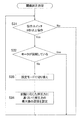
次に、圧力センサ15における押圧力の最大値の閾値を任意に設定するときの処理の流れを、図5に示すフローチャートに従って説明する。この処理は、モータ制御部16によって行われる。
<About output adjustment means>
Next, the flow of processing when arbitrarily setting the threshold value of the maximum pressing force in the
ステップS11では、操作スイッチ13が3秒以上続けて押されたか否かを判断する。操作スイッチ13が3秒以上押されたと判断すると、ステップS12へ移行する。
In step S11, it is determined whether the
ステップS12では、モータ8が回転しているか否かを判断する。すなわち、モータ8の回転停止を待って、以降の処理を実行する。
In step S12, it is determined whether the
モータ8の回転が停止している場合は、ステップS12からステップS13に移行する。ステップS13では、押圧力の最大値の閾値を設定するための設定モードへ切り替えを行う。
When the rotation of the
設定モードへ切り替え後、押圧操作部12が押圧されると、ステップS14で、このときの押圧力に基づいて押圧力の最大値の閾値を設定する。このとき、例えば、押圧力を複数回計測して、その押圧力の平均値に基づいて押圧力の最大値の閾値を設定することにより、押圧力に多少のばらつきがあっても、平均値に基づいて押圧力の最大値の閾値が設定されるため、より押圧力の不足や過剰が生じにくくなる。
When the
<第2実施形態>
本発明の第2実施形態における出力調整手段の処理の流れを、図6に従って説明する。なお、第2実施形態におけるリール本体1は、第1実施形態と同じ構成のため、説明を省略する。また、モータ制御部16によって行われるモータ制御処理についても、第1実施形態と同様のため説明を省略する。
<Second Embodiment>
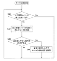
The processing flow of the output adjusting means in the second embodiment of the present invention will be described with reference to FIG. Since the
第2実施形態においても、モータ制御部16によって本処理が行われる。そして、ステップS24以外の処理は図5と同様であるので、ここでは、ステップS24で実行される押圧力の最大値の閾値を設定する処理のみを説明する。すなわち、ステップS24では、最大押圧力の所定範囲(例えば、最大押圧力の80%)に基づいて押圧力の最大値の閾値を設定する。なお、最大押圧力の所定範囲は、これに限定されるものではない。
Also in the second embodiment, this processing is performed by the
<第3実施形態>
本発明の第3実施形態における出力調整手段の処理の流れを、図7に従って説明する。なお、第3実施形態におけるリール本体1は、第1実施形態と同じ構成のため、説明を省略する。また、モータ制御部16によって行われるモータ制御処理についても、第1実施形態と同様のため説明を省略する。
<Third Embodiment>
The processing flow of the output adjusting means in the third embodiment of the present invention will be described with reference to FIG. Since the
第3実施形態においても、モータ制御部16によって本処理が行われる。そして、ステップS34以外の処理は図5と同様であるので、ここでは、ステップS34で実行される押圧力の最大値の閾値を設定する処理のみを説明する。
Also in the third embodiment, this processing is performed by the
ここで、第3実施形態では、複数段階(例えば5段階)に対応する閾値が予め設定されている。設定モードへ切り替え後、任意の段階が選択されると、ステップS34でその段階に応じた押圧力に基づいて押圧力の最大値の閾値を設定する。この場合は、押圧力の最大値の閾値の設定、又は変更をするときに押圧力を測定しなくてもよいため、容易に押圧力の最大値の閾値を設定、又は変更を行うことができる。 Here, in the third embodiment, threshold values corresponding to a plurality of stages (for example, five stages) are set in advance. When an arbitrary stage is selected after switching to the setting mode, the threshold value of the maximum value of the pressing force is set based on the pressing force corresponding to the stage in step S34. In this case, since it is not necessary to measure the pressing force when setting or changing the threshold value of the maximum pressing force, it is possible to easily set or change the threshold value of the maximum pressing force. ..
<第4実施形態>
第4実施形態の電動リールは、第1実施形態の構成とほぼ同じであり、モータ制御部16の制御処理方法のみが異なる。すなわち、出力調整レバー9の操作によりモータ8が駆動しているとき、押圧操作部12を押圧している間だけ、押圧力に応じてモータ8の出力(例えば回転速度)を減少又は停止する、といった点のみが第1実施形態と異なっている。従って、ここでは図8に示すフローチャートに沿って第4実施形態におけるモータ制御部16の処理の流れについてのみ説明する。
<Fourth Embodiment>
The electric reel of the fourth embodiment has almost the same configuration as that of the first embodiment, and is different only in the control processing method of the
<モータ制御部の処理の流れ>
まず、ステップS41で、出力調整レバー9が停止位置(出力調整レバー9によるモータ8の回転が生じない位置)にあるか否かを判断する。出力調整レバー9が停止位置にある場合は、モータ制御処理は実行されない。そして、出力調整レバー9が停止位置になければ、ステップS42へ移行する。
<Processing flow of motor control unit>
First, in step S41, it is determined whether or not the output adjusting lever 9 is at the stop position (a position where the
ステップS42では、出力調整レバー9の位置に応じた出力で(例えば、ここでは所定のスプール回転速度となるように)モータ8を回転させる。なお、負荷がかかってスプール回転速度が低下した時には所定の回転速度を保つようにフィードバック制御されている。
In step S42, the
ステップS43では、圧力センサ15から電気信号の出力があるか否かを判断する。電気信号の出力があれば、ステップS44へ移行する。
In step S43, it is determined whether the
ステップS44で、圧力センサ15から出力されている電気信号に応じて、モータ8の出力を減少(例えば、ここではスプール回転速度を減速)させる。このとき、押圧操作部12の押圧力が大きくなるに従って、モータ8の出力が減少、すなわちモータ8の回転速度が減速するように制御する。これにより、釣り人が押圧操作部12を強く押せば、出力調整レバー9によって設定されたモータ8の回転速度が大きく減速し、釣り人の感覚とモータ8の回転速度とが整合するので、モータ8の回転速度の調整が容易になる。なお、押圧力に応じてモータ8の回転速度が減速する場合、押圧力が最大になった時にモータ8の回転を停止するように制御してもよい。
In step S44, the output of the
第4実施形態においても、もちろん第1実施形態と同様に圧力センサ15における押圧力の最大値の閾値を任意に設定するための出力調整手段を備えている。
Similarly to the first embodiment, the fourth embodiment also includes output adjusting means for arbitrarily setting the threshold value of the maximum value of the pressing force in the
<第5実施形態>
図9及び図10は、本発明の第5実施形態における電動リールを示す。第5実施形態の電動リールは、出力調整部材である第1実施形態の出力調整レバー9を、回動式の出力調整部材20にしたものである。さらに、第5実施形態における押圧操作部は、出力調整部材20に一体的に設けられている。出力調整部材20を径方向に押圧する(すなわち、出力調整部材20を内部に押し込む)ことによって、その押圧力に応じた出力でモータ8が駆動される。
<Fifth Embodiment>
9 and 10 show an electric reel according to the fifth embodiment of the present invention. In the electric reel of the fifth embodiment, the output adjusting lever 9 of the first embodiment, which is the output adjusting member, is replaced with a rotary
第5実施形態におけるモータ8は、図10に示すように、スプール2の前方に配置されている。それ以外は、第1実施形態とほぼ同様の構成のため、以下からは、第1実施形態と異なる構成についてのみ説明を行う。なお、図10及び図11では、第1実施形態と同様の構成については、同じ符号を付している。
The
出力調整部材20は、モータ8の出力を複数段階(例えば、10段階以上であり、この実施形態では、31段階)に制御するためのものであり、図9及び図10に示すように、第1側板6aと第1側カバー7aとの間に設けられる。出力調整部材20は、ダイヤル状に形成され、カウンタケース5のケース部材21の後部の外側面に立設された図示しない支持軸に回動自在に装着されている。この実施形態における出力調整部材20の回動角度は、例えば80°から120°の範囲である。ただし、回動角度はこれに限定されない。
The
出力調整部材20の支持軸の支持部には、圧力センサ15が設けられている。出力調整部材20を径方向に押圧することにより、その押圧力に応じた出力でモータ8が駆動される。なお、出力調整部材20における押圧操作部を出力調整部材20の表面に設けてもよい。
A
出力調整部材20が押圧されたときのモータ制御部16によって行われるモータ制御処理の流れは、第1実施形態で説明した図4に示すフローチャートと同様であり、図4のステップS1における出力調整レバー9が出力調整部材20に替わるだけであるため、説明を省略する。
The flow of the motor control process performed by the
第5実施形態においても、第1実施形態と同様に圧力センサ15における押圧力の最大値の閾値を任意に設定するための出力調整手段を備えている。処理の流れは、前述した図5のフローチャートと同じ流れであるため、説明を省略する。
Similarly to the first embodiment, the fifth embodiment also includes output adjusting means for arbitrarily setting the threshold value of the maximum value of the pressing force in the
<第6実施形態>
図11は、本発明の第6実施形態における電動リールを示す。第6実施形態の電動リールは、第1実施形態の出力調整レバーを押圧操作部22に換えたものである。これ以外は、第1実施形態とほぼ同様の構成であるため、以下からは異なる構成についてのみ説明を行う。なお、図11では、第1実施形態と同様の構成については、同じ符号を付している。
<Sixth Embodiment>
FIG. 11 shows an electric reel according to the sixth embodiment of the present invention. In the electric reel of the sixth embodiment, the output adjusting lever of the first embodiment is replaced with the
押圧操作部22は、カウンタケース5の上面部に設けられており、操作スイッチ13の左側、すなわちハンドルとは反対側に偏倚して配置されている。 押圧操作部22は、モータ8の出力を複数段階(例えば、10段階以上であり、本実施形態では、31段階)に制御する。
The
押圧操作部22は、第1実施形態と同様に圧力センサ15を有しており、押圧力の大きさに応じた検出値を電気信号として、制御部14のモータ制御部16に出力する。押圧操作部22を押圧している間だけ、押圧力に応じた出力でモータ8が駆動される。
The
<モータ制御部の処理の流れ>
次に、電動リールの電源がオン状態のとき、制御部14のモータ制御部16によって行われるモータ制御処理の流れを、図12に示すフローチャートに従って説明する。
<Processing flow of motor control unit>
Next, the flow of the motor control processing performed by the
ステップS51で、圧力センサ15から電気信号の出力があるか否かを判断する。電気信号の出力があれば、ステップS52へ移行する。出力がなければ、モータ制御処理は実行されない。
In step S51, it is determined whether the
ステップS52では、圧力センサ15から出力された電気信号に応じた出力で(例えば、ここでは所定のスプール回転速度となるように)モータ8を回転させる。このとき、押圧力が大きくなるに従って、モータ8の出力が大きく(ここではスプール回転速度が早く)なるように制御することで、釣り人が押圧操作部22を強く押せばモータ8の回転速度が早くなり、釣り人の感覚とモータ8の出力とが整合するので、モータ8の出力の調整が容易になる。なお、負荷がかかってスプール回転速度が低下した時には所定の回転速度を保つようにフィードバック制御されている。
In step S52, the
第6実施形態においても、もちろん第1実施形態と同様に圧力センサ15における押圧力の最大値の閾値を任意に設定するための出力調整手段を備えている。
In the sixth embodiment, of course, similarly to the first embodiment, output adjusting means for arbitrarily setting the threshold value of the maximum value of the pressing force in the
<その他の実施形態>
(a)第1から第4実施形態における出力調整レバー9を、第5実施形態で採用している回動式の出力調整部材20にしてもよい。
<Other embodiments>
(A) The output adjusting lever 9 in the first to fourth embodiments may be replaced with the rotary
(b)第4から第6実施形態における出力調整手段は、第2又は第3実施形態における出力調整手段でもよい。 (B) The output adjusting means in the fourth to sixth embodiments may be the output adjusting means in the second or third embodiment.
(c)第5実施形態において押圧力に応じた出力でモータ8が駆動されるとき、第4実施形態で採用しているように、押圧力に応じてモータ8の出力(例えば回転速度)を減少又は停止するように制御してもよい。
(C) When the
(d)圧力センサ15は感圧素子のような単体部品でなく、大きなばね定数のばねで押圧された部材の微小な変位量に応じて出力するものであってもよい。
(D) The
(e)前述の実施形態ではモータ出力としてスプール2の回転速度を検出し、フィードバック制御していたが、モータに供給される電流値を制御して巻き上げトルクが所定値となるようにしてもよい。あるいはスプール2の糸巻径を算出して張力が所定値になるように制御してもよい。これらの場合、押圧操作部と出力調整部材で制御する対象を変えてもよい。
(E) In the above-described embodiment, the rotation speed of the
(f)第1から第4実施形態における押圧操作部12は、カウンタケース5から突出したものに限られない。また、第6実施形態における押圧操作部22は、カウンタケース5から突出していてもよい。また、押圧操作部22は、上記実施形態の位置に限定されるものではない。カウンタケース5そのものを押圧操作部にしてもよい。
(F) The
1 リール本体
2 スプール
8 モータ
9 出力調整レバー
12 押圧操作部
14 制御部
15 圧力センサ
16 モータ制御部
20 出力調整部材
22 押圧操作部
1
Claims (10)
押圧力に応じて出力が変化する圧力センサを有し、前記リール本体に設けられた押圧操作部と、
前記圧力センサの出力に応じて前記モータのモータ出力を制御するモータ制御手段と、
前記圧力センサにおける前記押圧力の最大値の閾値を任意に設定するための出力調整手段と、
を備え、
前記モータ制御手段は、前記押圧力が前記出力調整手段によって設定された前記押圧力の最大値の閾値に近づくに従って前記モータ出力を大きくする、電動リールのモータ制御装置。 A motor control device for an electric reel that drives a spool that is rotatably mounted on a reel body by a motor,
A pressure sensor having an output that changes according to a pressing force, and a pressing operation section provided on the reel unit,
Motor control means for controlling the motor output of the motor according to the output of the pressure sensor,
Output adjusting means for arbitrarily setting the threshold value of the maximum value of the pressing force in the pressure sensor,
Equipped with
The motor control device for an electric reel, wherein the motor control means increases the motor output as the pressing force approaches a threshold value of the maximum value of the pressing force set by the output adjusting means .
押圧力に応じて出力が変化する圧力センサを有し、前記リール本体に設けられた押圧操作部と、
前記モータのモータ出力を制御し、前記圧力センサの出力に応じて前記モータ出力を減少させる出力減少手段を有するモータ制御手段と、
前記圧力センサにおける前記押圧力の最大値の閾値を任意に設定するための出力調整手段と、
を備え、
前記出力減少手段は、前記押圧力が前記出力調整手段によって設定された前記押圧力の最大値の閾値に近づくに従って前記モータ出力を小さくする、電動リールのモータ制御装置。 A motor control device for an electric reel that drives a spool that is rotatably mounted on a reel body by a motor,
A pressure sensor having an output that changes according to a pressing force, and a pressing operation section provided on the reel unit,
A motor control unit that controls the motor output of the motor, and has an output reduction unit that reduces the motor output according to the output of the pressure sensor;
Output adjusting means for arbitrarily setting the threshold value of the maximum value of the pressing force in the pressure sensor,
Equipped with
A motor control device for an electric reel, wherein the output reducing means reduces the motor output as the pressing force approaches a threshold value of the maximum value of the pressing force set by the output adjusting means .
前記モータ制御手段は、前記モータ出力を、前記出力調整部材の操作によって設定された出力に制御するとともに、前記出力調整部材の操作によって前記モータが回転していないとき、前記圧力センサの出力に応じて前記モータ出力を制御する、請求項1に記載の電動リールのモータ制御装置。 Further comprising an output adjusting member provided on the reel body for adjusting the rotation of the motor stepwise from a stopped state,
The motor control means controls the motor output to an output set by operating the output adjusting member, and responds to the output of the pressure sensor when the motor is not rotating by operating the output adjusting member. The motor control device for the electric reel according to claim 1 , wherein the motor output is controlled by an electric reel.
前記モータ制御手段は、前記モータ出力を、前記出力調整部材の操作によって設定された出力に制御するとともに、前記出力調整部材の操作によって前記モータが回転しているとき、前記出力調整部材によって設定された前記モータ出力を、前記出力減少手段によって減少させる、請求項2に記載の電動リールのモータ制御装置。 Further comprising an output adjusting member provided on the reel body for adjusting the rotation of the motor stepwise from a stopped state,
The motor control means controls the motor output to an output set by operating the output adjusting member, and is set by the output adjusting member when the motor is rotating by operating the output adjusting member. 3. The electric reel motor control device according to claim 2 , wherein the motor output is reduced by the output reduction means.
8. The electric reel motor control according to claim 1, wherein the output adjusting unit sets a threshold value of the maximum value of the pressing force from a plurality of preset pressing force values. apparatus.
Priority Applications (4)
| Application Number | Priority Date | Filing Date | Title |
|---|---|---|---|
| JP2016083319A JP6726513B2 (en) | 2016-04-19 | 2016-04-19 | Electric reel motor controller |
| KR1020170007939A KR102628498B1 (en) | 2016-04-19 | 2017-01-17 | Motor control apparatus for electrical fishing reel |
| TW106108562A TWI714737B (en) | 2016-04-19 | 2017-03-15 | Motor control device of electric reel |
| CN201710226854.5A CN107361032B (en) | 2016-04-19 | 2017-04-06 | Motor control device for electric fishing reel |
Applications Claiming Priority (1)
| Application Number | Priority Date | Filing Date | Title |
|---|---|---|---|
| JP2016083319A JP6726513B2 (en) | 2016-04-19 | 2016-04-19 | Electric reel motor controller |
Publications (3)
| Publication Number | Publication Date |
|---|---|
| JP2017192319A JP2017192319A (en) | 2017-10-26 |
| JP2017192319A5 JP2017192319A5 (en) | 2019-04-11 |
| JP6726513B2 true JP6726513B2 (en) | 2020-07-22 |
Family
ID=60154231
Family Applications (1)
| Application Number | Title | Priority Date | Filing Date |
|---|---|---|---|
| JP2016083319A Active JP6726513B2 (en) | 2016-04-19 | 2016-04-19 | Electric reel motor controller |
Country Status (4)
| Country | Link |
|---|---|
| JP (1) | JP6726513B2 (en) |
| KR (1) | KR102628498B1 (en) |
| CN (1) | CN107361032B (en) |
| TW (1) | TWI714737B (en) |
Families Citing this family (1)
| Publication number | Priority date | Publication date | Assignee | Title |
|---|---|---|---|---|
| JP7113686B2 (en) * | 2018-07-11 | 2022-08-05 | 株式会社シマノ | electric reel |
Family Cites Families (18)
| Publication number | Priority date | Publication date | Assignee | Title |
|---|---|---|---|---|
| JP3386094B2 (en) * | 1996-02-22 | 2003-03-10 | ダイワ精工株式会社 | Fishing reel |
| JPH10337138A (en) * | 1997-06-04 | 1998-12-22 | Ryobi Ltd | Electric reel for fishing |
| JP2000125722A (en) * | 1998-10-22 | 2000-05-09 | Shimano Inc | Electrically driven reel |
| JP2000253784A (en) * | 1999-03-11 | 2000-09-19 | Ryobi Ltd | Electrically driven fishing reel |
| JP2001169701A (en) * | 1999-12-16 | 2001-06-26 | Daiwa Seiko Inc | Power reel for fishing |
| JP2002125540A (en) * | 2000-10-31 | 2002-05-08 | Daiwa Seiko Inc | Reel for fishing |
| JP2002367465A (en) * | 2001-06-05 | 2002-12-20 | Fujikura Ltd | Multistage switch and light changeover switch for automobile |
| TWI234115B (en) * | 2002-04-03 | 2005-06-11 | Htc Corp | Method and device of setting threshold pressure for touch panel |
| JP2004177993A (en) * | 2002-11-22 | 2004-06-24 | Panasonic Mobile Communications Co Ltd | Mobile terminal with pressure sensor, and program executable by mobile terminal with pressure sensor |
| JP4408378B2 (en) * | 2004-02-19 | 2010-02-03 | グローブライド株式会社 | Fishing electric reel |
| JP2007252256A (en) * | 2006-03-22 | 2007-10-04 | Daiwa Seiko Inc | Electric fishing reel |
| JP2011050270A (en) * | 2009-08-31 | 2011-03-17 | Globeride Inc | Electric fishing reel |
| JP5640532B2 (en) * | 2010-08-02 | 2014-12-17 | 日産自動車株式会社 | On-vehicle device operating device and contact determination method |
| JP2012048504A (en) * | 2010-08-26 | 2012-03-08 | Kyocera Corp | Input device |
| US9060500B2 (en) * | 2012-04-18 | 2015-06-23 | Paul Lauzon | Monomanuel electric fishing rod and reel |
| JP6043664B2 (en) * | 2013-03-21 | 2016-12-14 | シャープ株式会社 | Electronics |
| CN204292035U (en) * | 2014-12-04 | 2015-04-29 | 宁波播阳灯饰有限公司 | A kind of fishing line reel with warning function |
| CN104686465B (en) * | 2015-03-06 | 2017-04-12 | 安徽省安国渔具有限公司 | Cone-pulley type fish wire classified and independent winding device |
-
2016
- 2016-04-19 JP JP2016083319A patent/JP6726513B2/en active Active
-
2017
- 2017-01-17 KR KR1020170007939A patent/KR102628498B1/en active IP Right Grant
- 2017-03-15 TW TW106108562A patent/TWI714737B/en active
- 2017-04-06 CN CN201710226854.5A patent/CN107361032B/en active Active
Also Published As
| Publication number | Publication date |
|---|---|
| JP2017192319A (en) | 2017-10-26 |
| CN107361032A (en) | 2017-11-21 |
| TWI714737B (en) | 2021-01-01 |
| CN107361032B (en) | 2021-12-03 |
| TW201808095A (en) | 2018-03-16 |
| KR102628498B1 (en) | 2024-01-24 |
| KR20170119619A (en) | 2017-10-27 |
Similar Documents
| Publication | Publication Date | Title |
|---|---|---|
| JP7330001B2 (en) | Motor control device for electric reel | |
| TWI595833B (en) | Control apparatus for electrical reel | |
| TWI731089B (en) | Motor control device of electric reel | |
| JP6726513B2 (en) | Electric reel motor controller | |
| JP4584108B2 (en) | Fishing machine and control method thereof | |
| JP6758073B2 (en) | Electric reel motor control device | |
| JP6758074B2 (en) | Electric reel motor control device | |
| JP2017189150A5 (en) | ||
| JP2017189151A5 (en) | ||
| JP2017192319A5 (en) | ||
| JP7065590B2 (en) | Electric reel motor control device | |
| JP2019080540A5 (en) | ||
| TWI769276B (en) | Motor control device for electric cord reel | |
| JP2019080539A5 (en) | ||
| KR20180008275A (en) | Motor control device for motor driven reel |
Legal Events
| Date | Code | Title | Description |
|---|---|---|---|
| A521 | Request for written amendment filed |
Free format text: JAPANESE INTERMEDIATE CODE: A523 Effective date: 20190301 |
|
| A621 | Written request for application examination |
Free format text: JAPANESE INTERMEDIATE CODE: A621 Effective date: 20190301 |
|
| A977 | Report on retrieval |
Free format text: JAPANESE INTERMEDIATE CODE: A971007 Effective date: 20191226 |
|
| A131 | Notification of reasons for refusal |
Free format text: JAPANESE INTERMEDIATE CODE: A131 Effective date: 20200114 |
|
| A131 | Notification of reasons for refusal |
Free format text: JAPANESE INTERMEDIATE CODE: A131 Effective date: 20200324 |
|
| A521 | Request for written amendment filed |
Free format text: JAPANESE INTERMEDIATE CODE: A523 Effective date: 20200522 |
|
| TRDD | Decision of grant or rejection written | ||
| A01 | Written decision to grant a patent or to grant a registration (utility model) |
Free format text: JAPANESE INTERMEDIATE CODE: A01 Effective date: 20200616 |
|
| A61 | First payment of annual fees (during grant procedure) |
Free format text: JAPANESE INTERMEDIATE CODE: A61 Effective date: 20200629 |
|
| R150 | Certificate of patent or registration of utility model |
Ref document number: 6726513 Country of ref document: JP Free format text: JAPANESE INTERMEDIATE CODE: R150 |
|
| R250 | Receipt of annual fees |
Free format text: JAPANESE INTERMEDIATE CODE: R250 |