JP6720939B2 - Information presentation control device and information presentation control program - Google Patents
Information presentation control device and information presentation control program Download PDFInfo
- Publication number
- JP6720939B2 JP6720939B2 JP2017150912A JP2017150912A JP6720939B2 JP 6720939 B2 JP6720939 B2 JP 6720939B2 JP 2017150912 A JP2017150912 A JP 2017150912A JP 2017150912 A JP2017150912 A JP 2017150912A JP 6720939 B2 JP6720939 B2 JP 6720939B2
- Authority
- JP
- Japan
- Prior art keywords
- presentation
- behavior
- vibration
- information
- vehicle
- Prior art date
- Legal status (The legal status is an assumption and is not a legal conclusion. Google has not performed a legal analysis and makes no representation as to the accuracy of the status listed.)
- Expired - Fee Related
Links
- 230000008859 change Effects 0.000 claims description 66
- 230000001133 acceleration Effects 0.000 claims description 61
- 238000012545 processing Methods 0.000 claims description 24
- 230000003542 behavioural effect Effects 0.000 claims 1
- 230000010355 oscillation Effects 0.000 claims 1
- 230000007704 transition Effects 0.000 description 32
- 238000000034 method Methods 0.000 description 30
- 230000008569 process Effects 0.000 description 28
- 210000002683 foot Anatomy 0.000 description 27
- 230000009471 action Effects 0.000 description 15
- 239000000463 material Substances 0.000 description 14
- 230000006870 function Effects 0.000 description 13
- 238000003780 insertion Methods 0.000 description 10
- 230000037431 insertion Effects 0.000 description 10
- 210000004932 little finger Anatomy 0.000 description 9
- 230000001939 inductive effect Effects 0.000 description 8
- 230000002093 peripheral effect Effects 0.000 description 8
- 230000006698 induction Effects 0.000 description 7
- 230000007246 mechanism Effects 0.000 description 7
- 230000035807 sensation Effects 0.000 description 7
- 230000004048 modification Effects 0.000 description 5
- 238000012986 modification Methods 0.000 description 5
- 230000035945 sensitivity Effects 0.000 description 5
- 210000003371 toe Anatomy 0.000 description 5
- 238000012508 change request Methods 0.000 description 4
- 230000000392 somatic effect Effects 0.000 description 4
- 244000309466 calf Species 0.000 description 3
- 230000007423 decrease Effects 0.000 description 3
- 238000001514 detection method Methods 0.000 description 3
- 230000006866 deterioration Effects 0.000 description 3
- 239000007769 metal material Substances 0.000 description 3
- 210000000452 mid-foot Anatomy 0.000 description 3
- 238000010586 diagram Methods 0.000 description 2
- 210000003811 finger Anatomy 0.000 description 2
- 210000001872 metatarsal bone Anatomy 0.000 description 2
- 230000003287 optical effect Effects 0.000 description 2
- 230000001902 propagating effect Effects 0.000 description 2
- 230000000630 rising effect Effects 0.000 description 2
- 230000003238 somatosensory effect Effects 0.000 description 2
- 230000001360 synchronised effect Effects 0.000 description 2
- 210000003813 thumb Anatomy 0.000 description 2
- 208000019901 Anxiety disease Diseases 0.000 description 1
- JOYRKODLDBILNP-UHFFFAOYSA-N Ethyl urethane Chemical compound CCOC(N)=O JOYRKODLDBILNP-UHFFFAOYSA-N 0.000 description 1
- 230000036506 anxiety Effects 0.000 description 1
- 238000013459 approach Methods 0.000 description 1
- 238000004891 communication Methods 0.000 description 1
- 239000002131 composite material Substances 0.000 description 1
- 150000001875 compounds Chemical class 0.000 description 1
- 230000008034 disappearance Effects 0.000 description 1
- 238000005516 engineering process Methods 0.000 description 1
- 238000007667 floating Methods 0.000 description 1
- 230000005484 gravity Effects 0.000 description 1
- 239000010985 leather Substances 0.000 description 1
- 238000005259 measurement Methods 0.000 description 1
- 230000003278 mimic effect Effects 0.000 description 1
- 230000010349 pulsation Effects 0.000 description 1
- 230000009467 reduction Effects 0.000 description 1
- 239000011347 resin Substances 0.000 description 1
- 229920005989 resin Polymers 0.000 description 1
- 239000004065 semiconductor Substances 0.000 description 1
Images


Classifications
-
- B—PERFORMING OPERATIONS; TRANSPORTING
- B60—VEHICLES IN GENERAL
- B60N—SEATS SPECIALLY ADAPTED FOR VEHICLES; VEHICLE PASSENGER ACCOMMODATION NOT OTHERWISE PROVIDED FOR
- B60N3/00—Arrangements or adaptations of other passenger fittings, not otherwise provided for
- B60N3/06—Arrangements or adaptations of other passenger fittings, not otherwise provided for of footrests
-
- B—PERFORMING OPERATIONS; TRANSPORTING
- B60—VEHICLES IN GENERAL
- B60K—ARRANGEMENT OR MOUNTING OF PROPULSION UNITS OR OF TRANSMISSIONS IN VEHICLES; ARRANGEMENT OR MOUNTING OF PLURAL DIVERSE PRIME-MOVERS IN VEHICLES; AUXILIARY DRIVES FOR VEHICLES; INSTRUMENTATION OR DASHBOARDS FOR VEHICLES; ARRANGEMENTS IN CONNECTION WITH COOLING, AIR INTAKE, GAS EXHAUST OR FUEL SUPPLY OF PROPULSION UNITS IN VEHICLES
- B60K35/00—Arrangement of adaptations of instruments
-
- B60K35/10—
-
- B60K35/25—
-
- B60K35/28—
-
- B—PERFORMING OPERATIONS; TRANSPORTING
- B60—VEHICLES IN GENERAL
- B60W—CONJOINT CONTROL OF VEHICLE SUB-UNITS OF DIFFERENT TYPE OR DIFFERENT FUNCTION; CONTROL SYSTEMS SPECIALLY ADAPTED FOR HYBRID VEHICLES; ROAD VEHICLE DRIVE CONTROL SYSTEMS FOR PURPOSES NOT RELATED TO THE CONTROL OF A PARTICULAR SUB-UNIT
- B60W40/00—Estimation or calculation of non-directly measurable driving parameters for road vehicle drive control systems not related to the control of a particular sub unit, e.g. by using mathematical models
- B60W40/08—Estimation or calculation of non-directly measurable driving parameters for road vehicle drive control systems not related to the control of a particular sub unit, e.g. by using mathematical models related to drivers or passengers
- B60W40/09—Driving style or behaviour
-
- B—PERFORMING OPERATIONS; TRANSPORTING
- B60—VEHICLES IN GENERAL
- B60W—CONJOINT CONTROL OF VEHICLE SUB-UNITS OF DIFFERENT TYPE OR DIFFERENT FUNCTION; CONTROL SYSTEMS SPECIALLY ADAPTED FOR HYBRID VEHICLES; ROAD VEHICLE DRIVE CONTROL SYSTEMS FOR PURPOSES NOT RELATED TO THE CONTROL OF A PARTICULAR SUB-UNIT
- B60W50/00—Details of control systems for road vehicle drive control not related to the control of a particular sub-unit, e.g. process diagnostic or vehicle driver interfaces
- B60W50/08—Interaction between the driver and the control system
- B60W50/14—Means for informing the driver, warning the driver or prompting a driver intervention
- B60W50/16—Tactile feedback to the driver, e.g. vibration or force feedback to the driver on the steering wheel or the accelerator pedal
-
- G—PHYSICS
- G08—SIGNALLING
- G08G—TRAFFIC CONTROL SYSTEMS
- G08G1/00—Traffic control systems for road vehicles
- G08G1/09—Arrangements for giving variable traffic instructions
- G08G1/0962—Arrangements for giving variable traffic instructions having an indicator mounted inside the vehicle, e.g. giving voice messages
-
- B—PERFORMING OPERATIONS; TRANSPORTING
- B60—VEHICLES IN GENERAL
- B60K—ARRANGEMENT OR MOUNTING OF PROPULSION UNITS OR OF TRANSMISSIONS IN VEHICLES; ARRANGEMENT OR MOUNTING OF PLURAL DIVERSE PRIME-MOVERS IN VEHICLES; AUXILIARY DRIVES FOR VEHICLES; INSTRUMENTATION OR DASHBOARDS FOR VEHICLES; ARRANGEMENTS IN CONNECTION WITH COOLING, AIR INTAKE, GAS EXHAUST OR FUEL SUPPLY OF PROPULSION UNITS IN VEHICLES
- B60K26/00—Arrangements or mounting of propulsion unit control devices in vehicles
- B60K26/02—Arrangements or mounting of propulsion unit control devices in vehicles of initiating means or elements
- B60K26/021—Arrangements or mounting of propulsion unit control devices in vehicles of initiating means or elements with means for providing feel, e.g. by changing pedal force characteristics
- B60K2026/022—Arrangements or mounting of propulsion unit control devices in vehicles of initiating means or elements with means for providing feel, e.g. by changing pedal force characteristics with tactile feedback from a controller, e.g. vibrations
-
- B60K2360/178—
-
- B—PERFORMING OPERATIONS; TRANSPORTING
- B60—VEHICLES IN GENERAL
- B60K—ARRANGEMENT OR MOUNTING OF PROPULSION UNITS OR OF TRANSMISSIONS IN VEHICLES; ARRANGEMENT OR MOUNTING OF PLURAL DIVERSE PRIME-MOVERS IN VEHICLES; AUXILIARY DRIVES FOR VEHICLES; INSTRUMENTATION OR DASHBOARDS FOR VEHICLES; ARRANGEMENTS IN CONNECTION WITH COOLING, AIR INTAKE, GAS EXHAUST OR FUEL SUPPLY OF PROPULSION UNITS IN VEHICLES
- B60K26/00—Arrangements or mounting of propulsion unit control devices in vehicles
- B60K26/02—Arrangements or mounting of propulsion unit control devices in vehicles of initiating means or elements
- B60K26/021—Arrangements or mounting of propulsion unit control devices in vehicles of initiating means or elements with means for providing feel, e.g. by changing pedal force characteristics
-
- B—PERFORMING OPERATIONS; TRANSPORTING
- B60—VEHICLES IN GENERAL
- B60N—SEATS SPECIALLY ADAPTED FOR VEHICLES; VEHICLE PASSENGER ACCOMMODATION NOT OTHERWISE PROVIDED FOR
- B60N2/00—Seats specially adapted for vehicles; Arrangement or mounting of seats in vehicles
- B60N2/90—Details or parts not otherwise provided for
- B60N2002/981—Warning systems, e.g. the seat or seat parts vibrates to warn the passenger when facing a danger
Description
本開示は、車両のユーザに情報を提示する情報提示制御の技術に関する。 The present disclosure relates to information presentation control technology for presenting information to a vehicle user.
従来、体性感覚を通じてユーザに情報提示する構成として、例えば特許文献1には、足置き場を移動させるフットレスト、及び背もたれを移動させるシート等が開示されている。フットレスト及びシートは、足置き場及び背もたれ等の移動により、自律走行する車両の将来の挙動変化の内容を、挙動変化の発生以前にユーザに通知できる。一例として、特許文献1では、減速の予告として足置き場が後傾された後に、実際の車両の減速が開始される。
BACKGROUND ART Conventionally, for example,
しかし、フットレストの足置き場及びシートの背もたれ等を動かすための機構は、大型化し易い。そのため、車両への搭載性を確保が困難となり得た。 However, the mechanism for moving the footrest of the footrest, the seat back, and the like tends to increase in size. Therefore, it may be difficult to secure mountability on the vehicle.
本開示は、情報提示のための構成の車両への搭載性を確保したうえで、体性感覚を通じたユーザへの通知が可能な情報提示制御装置の提供を目的とする。 An object of the present disclosure is to provide an information presentation control device capable of notifying a user through a somatic sensation while ensuring mountability of a configuration for presenting information in a vehicle.
上記目的を達成するため、開示された一つの態様は、自動運転可能な車両に搭乗するユーザの足裏の感覚を通じて当該ユーザに情報を提示するよう設けられた複数の提示面部(81a〜83a)を振動させる制御により、当該ユーザに情報を提示する情報提示制御装置であって、自律走行する車両の将来挙動を示した挙動情報を取得する情報取得部(51)と、挙動情報に基づき、ユーザに提示する挙動変化が車両に生じるか否かを判定する挙動判定部(52)と、挙動判定部にて提示すべきと判定された提示挙動変化の発生以前に、複数の提示面部の振動を個別に制御し、提示挙動変化の内容をユーザに予め通知する提示制御部(53)と、を備え、提示挙動変化によって車両に生じる加速度の方向に沿って並ぶ二つの提示面部のうち、加速度の方向に位置する一方を第一提示面部とし、他方を第二提示面部とすると、提示制御部は、第二提示面部の振動の停止後から第一提示面部の振動を開始するまでの第一オフ時間(T1f,T1b,T1r,T1l)と、第一提示面部の振動の停止後から第二提示面部の振動を開始するまでの第二オフ時間(T2f,T2b,T2r,T2l)とを規定し、第一オフ時間を第二オフ時間よりも短くする情報提示制御装置とされる。
また開示された一つの態様は、自動運転可能な車両に搭乗するユーザの足裏の感覚を通じて当該ユーザに情報を提示するよう設けられた複数の提示面部(81a〜83a)を振動させる制御により、当該ユーザに情報を提示する情報提示制御装置であって、自律走行する車両の将来挙動を示した挙動情報を取得する情報取得部(51)と、挙動情報に基づき、ユーザに提示する挙動変化が車両に生じるか否かを判定する挙動判定部(52)と、挙動判定部にて提示すべきと判定された提示挙動変化の発生以前に、複数の提示面部の振動を個別に制御し、提示挙動変化の内容をユーザに予め通知する提示制御部(53)と、を備え、提示挙動変化によって車両に生じる加速度の方向に沿って並ぶ二つの提示面部のうち、加速度の方向に位置する一方を第一提示面部とし、他方を第二提示面部とすると、提示制御部は、第一提示面部及び第二提示面部の両方の振動を開始させた後、第二提示面部の振動を第一提示面部よりも早く停止させる情報提示制御装置とされる。
In order to achieve the above object, one disclosed aspect is a plurality of presentation surface portions (81a to 83a) provided so as to present information to a user who rides in a vehicle capable of autonomous driving, through the feeling of the sole of the user. Is an information presentation control device that presents information to the user by controlling to vibrate, and an information acquisition unit (51) that acquires behavior information indicating future behavior of an autonomously traveling vehicle, and a user based on the behavior information. The behavior determination unit (52) that determines whether or not the behavior change to be presented to the vehicle occurs, and the vibrations of the plurality of presentation surface units before the occurrence of the presentation behavior change that the behavior determination unit determines to present. A presentation control unit (53) that individually controls and notifies the user of the details of the presentation behavior change in advance; and, of the two presentation surface units lined up in the direction of the acceleration generated in the vehicle by the presentation behavior change, If one of the first presentation surface portions located in the direction is the first presentation surface portion and the other is the second presentation surface portion, the presentation control unit makes the first off from the stop of the vibration of the second presentation surface portion to the start of the vibration of the first presentation surface portion. The time (T1f, T1b, T1r, T1l) and the second off time (T2f, T2b, T2r, T2l) from the stop of the vibration of the first presentation surface portion to the start of the vibration of the second presentation surface portion are defined. is an information presentation control unit you shorter than the first off-time second off-time.
Further, one aspect disclosed is a control that vibrates a plurality of presentation surface portions (81a to 83a) provided to present information to the user through the sensation of the sole of the user who rides in a vehicle capable of autonomous driving, An information presentation control device that presents information to the user, and an information acquisition unit (51) that acquires behavior information indicating future behavior of an autonomously traveling vehicle, and a behavior change presented to the user based on the behavior information. A behavior determination unit (52) that determines whether or not the vehicle is generated, and individually controls the vibration of the plurality of presentation surface units before the occurrence of the presentation behavior change that is determined to be presented by the behavior determination unit. A presentation control unit (53) for notifying the user of the content of the behavior change in advance, and one of the two presentation surface units arranged along the direction of the acceleration caused in the vehicle by the presentation behavior change, which is located in the acceleration direction. If the first presentation surface portion and the other is the second presentation surface portion, the presentation control unit starts the vibration of both the first presentation surface portion and the second presentation surface portion, and then the vibration of the second presentation surface portion is changed to the first presentation surface portion. The information presentation control device is configured to stop earlier than this.
また開示された一つの態様は、自動運転可能な車両に搭乗するユーザの足裏の感覚を通じて当該ユーザに情報を提示するよう設けられた複数の提示面部(81a〜83a)を振動させる制御により、当該ユーザに情報を提示する情報提示制御プログラムであって、少なくとも一つの処理部(41)を、自律走行する車両の将来挙動を示した挙動情報を取得する情報取得部(51)と、挙動情報に基づき、ユーザに提示する挙動変化が車両に生じるか否かを判定する挙動判定部(52)と、挙動判定部にて提示すべきと判定された提示挙動変化の発生以前に、複数の提示面部の振動を個別に制御し、提示挙動変化の内容をユーザに予め通知する提示制御部(53)として機能させ、提示挙動変化によって車両に生じる加速度の方向に沿って並ぶ二つの提示面部のうち、加速度の方向に位置する一方を第一提示面部とし、他方を第二提示面部とすると、提示制御部は、第二提示面部の振動の停止後から第一提示面部の振動を開始するまでの第一オフ時間(T1f,T1b,T1r,T1l)と、第一提示面部の振動の停止後から第二提示面部の振動を開始するまでの第二オフ時間(T2f,T2b,T2r,T2l)とを規定し、第一オフ時間を第二オフ時間よりも短くする情報提示制御プログラムとされる。
また開示された一つの態様は、自動運転可能な車両に搭乗するユーザの足裏の感覚を通じて当該ユーザに情報を提示するよう設けられた複数の提示面部(81a〜83a)を振動させる制御により、当該ユーザに情報を提示する情報提示制御プログラムであって、少なくとも一つの処理部(41)を、自律走行する車両の将来挙動を示した挙動情報を取得する情報取得部(51)と、挙動情報に基づき、ユーザに提示する挙動変化が車両に生じるか否かを判定する挙動判定部(52)と、挙動判定部にて提示すべきと判定された提示挙動変化の発生以前に、複数の提示面部の振動を個別に制御し、提示挙動変化の内容をユーザに予め通知する提示制御部(53)として機能させ、提示挙動変化によって車両に生じる加速度の方向に沿って並ぶ二つの提示面部のうち、加速度の方向に位置する一方を第一提示面部とし、他方を第二提示面部とすると、提示制御部は、第一提示面部及び第二提示面部の両方の振動を開始させた後、第二提示面部の振動を第一提示面部よりも早く停止させる情報提示制御プログラムとされる。
One embodiment also disclosed by the control to oscillate the plurality of presentation faces provided so that to present information to the user via the sense of the sole of the user boarding an automatic operable vehicle (81a~83a) An information presentation control program for presenting information to the user, the at least one processing unit (41) having an information acquisition unit (51) for acquiring behavior information indicating a future behavior of a vehicle traveling autonomously; Based on the information, a behavior determination unit (52) that determines whether or not a behavior change to be presented to the user occurs in the vehicle, and a plurality of presentation behavior changes before the occurrence of the presentation behavior change that is determined to be presented by the behavior determination unit. Vibration of the presentation surface section is individually controlled to function as a presentation control section (53) for notifying the user of the content of the presentation behavior change in advance, and two presentation surface sections lined up along the direction of the acceleration generated in the vehicle by the presentation behavior change. Of these, one positioned in the direction of acceleration is the first presentation surface portion, and the other is the second presentation surface portion, and the presentation control unit is from when the vibration of the second presentation surface portion is stopped until the vibration of the first presentation surface portion is started. First off time (T1f, T1b, T1r, T1l) and the second off time (T2f, T2b, T2r, T2l) from the stop of the vibration of the first presentation surface part to the start of the vibration of the second presentation surface part defining the door, it is an information presentation control program that shorter than the first off-time second off-time.
Further, one aspect disclosed is a control that vibrates a plurality of presentation surface portions (81a to 83a) provided to present information to the user through the sensation of the sole of the user who rides in a vehicle capable of autonomous driving, An information presentation control program for presenting information to the user, which includes at least one processing unit (41), an information acquisition unit (51) for acquiring behavior information indicating a future behavior of a vehicle that autonomously travels, and behavior information. Based on the above, a behavior determination unit (52) that determines whether or not a behavior change to be presented to the user occurs in the vehicle, and a plurality of presentations before the occurrence of the presentation behavior change that is determined to be presented by the behavior determination unit. Of the two presentation surface portions that are arranged along the direction of the acceleration that occurs in the vehicle due to the presentation behavior change, the vibration is controlled individually to function as a presentation control unit (53) that notifies the user of the content of the presentation behavior change in advance. , The one present in the direction of acceleration is the first presentation surface portion, and the other is the second presentation surface portion, the presentation control unit, after starting the vibration of both the first presentation surface portion and the second presentation surface portion, the second The program is an information presentation control program for stopping the vibration of the presentation surface portion earlier than the first presentation surface portion.
これらの態様のように、複数の提示面部の振動を個別に制御すれば、自律走行する車両に将来的に生じる挙動変化の内容が、ユーザに通知可能となる。このように振動によって将来挙動を通知可能であれば、フットレスト及びシート等を動かすための機構は、省略され得る。したがって、情報提示のための構成の車両への搭載性を確保したうえで、体性感覚を通じたユーザへの挙動変化の通知が可能になる。 By individually controlling the vibrations of the plurality of presentation surface portions as in these modes, it becomes possible to notify the user of the content of the behavior change that will occur in the vehicle that autonomously travels in the future. If the behavior can be notified by vibration in the future, the mechanism for moving the footrest, the seat and the like can be omitted. Therefore, it becomes possible to notify the user of the behavior change through the somatosensory while ensuring the mountability of the structure for presenting information in the vehicle.
尚、上記括弧内の参照番号は、後述する実施形態における具体的な構成との対応関係の一例を示すものにすぎず、技術的範囲を何ら制限するものではない。 It should be noted that the reference numerals in the above parentheses merely show an example of a correspondence relationship with a specific configuration in the embodiment described later, and do not limit the technical scope at all.
以下、本開示の複数の実施形態を図面に基づいて説明する。尚、各実施形態において対応する構成要素には同一の符号を付すことにより、重複する説明を省略する場合がある。各実施形態において構成の一部分のみを説明している場合、当該構成の他の部分については、先行して説明した他の実施形態の構成を適用することができる。また、各実施形態の説明において明示している構成の組み合わせばかりではなく、特に組み合わせに支障が生じなければ、明示していなくても複数の実施形態の構成同士を部分的に組み合わせることができる。そして、複数の実施形態及び変形例に記述された構成同士の明示されていない組み合わせも、以下の説明によって開示されているものとする。 Hereinafter, a plurality of embodiments of the present disclosure will be described with reference to the drawings. In addition, in each embodiment, the corresponding components may be denoted by the same reference numerals, and redundant description may be omitted. When only a part of the configuration is described in each embodiment, the configuration of the other embodiments described above can be applied to the other part of the configuration. Further, not only the combination of the configurations explicitly described in the description of each embodiment, but the configuration of a plurality of embodiments can be partially combined even if they are not explicitly described, unless the combination causes any trouble. Then, a combination in which the configurations described in the plurality of embodiments and the modifications are not explicitly disclosed is also disclosed by the following description.
(第一実施形態)
図1及び図2に示す本開示の第一実施形態において、情報提示制御装置の機能は、HCU(HMI(Human Machine Interface) Control Unit)40によって実現されている。HCU40は、フットレスト装置100及び駆動装置60等と共に振動提示システムを構成している。振動提示システムは、自動運転可能な車両に搭載され、車両の運転席11に着座したユーザ(以下、「運転者」)への情報提示を振動によって実施する。
(First embodiment)
In the first embodiment of the present disclosure shown in FIGS. 1 and 2, the function of the information presentation control device is realized by an HCU (HMI (Human Machine Interface) Control Unit) 40. The HCU 40 constitutes a vibration presentation system together with the
フットレスト装置100は、車両に搭載された複数のHMI機器のうちの一つである。フットレスト装置100は、車両に搭乗する運転者の足裏の載置を想定された載置面73に、複数の提示面部81a〜83aを有している。フットレスト装置100は、提示面部81a〜83aの振動により、運転者の足裏の感覚、具体的には振動覚を通じて、主に車両の自動運転に関連した情報を提示する。
The
フットレスト装置100は、図1及び図3に示すように、全体として長手の厚板状に形成されている。フットレスト装置100は、運転者の左足が置かれる載置面73を運転席11側に向けた姿勢で、車両に設けられた取付部16に取り付けられている。載置面73の長手方向LDは、車両の前後方向及び上下方向に対し垂直な縦断面に沿っている。載置面73の幅方向(短手方向)CDは、車両の左右方向に沿っている。載置面73は、車両の後方から前方へ向かうに従って、上方に傾斜した姿勢とされている。フットレスト装置100は、図3〜図5に示すように、フットレストベース70及び複数(三つ)の振動スピーカ81〜83等によって構成されている。
As shown in FIGS. 1 and 3, the
フットレストベース70は、ボルト等の締結部材によって車両の取付部16に固定されている。フットレストベース70は、上カバー部材71、下ベース板76、ベース緩衝材78及びスピーカ緩衝材79等によって構成されている。
The
上カバー部材71は、有底の浅い容器状である基材の底面に、薄い板状の化粧板72を貼り付けることによって形成されている。上カバー部材71は、全体として金属材料により形成されている。上カバー部材71は、支持壁部71a及び底壁部71bを有している。支持壁部71aは、底壁部71bの外縁に設けられており、底壁部71bに対して実質的に垂直に立設されている。支持壁部71aは、底壁部71bと下ベース板76との間の間隔を規定している。底壁部71bは、長手形状且つ平面状である載置面73を形成している。底壁部71bには、挿通開口74が設けられている。挿通開口74は、化粧板72を含む底壁部71bを板厚方向に貫通する真円状の開口である。挿通開口74は、互いに間隔を開けた配置にて、底壁部71bに三つ開口している。
The
下ベース板76は、金属材料によって平板状に形成されている。下ベース板76の外形形状は、上カバー部材71の底壁部71bと実質的に同一である。下ベース板76は、上カバー部材71に対し載置面73の反対側に位置している。下ベース板76の外縁部には、支持壁部71aの頂部が当接している。下ベース板76は、三つの振動スピーカ81〜83を個別に保持している。
The
ベース緩衝材78は、例えばウレタン等によって下ベース板76よりも厚いシート状に形成されている。ベース緩衝材78は、下ベース板76と取付部16の間に、厚さ方向に押し縮められた状態で配置されている。ベース緩衝材78を介して、フットレストベース70は、取付部16に強固に固定されている。こうした取り付けにより、各振動スピーカ81〜83の作動に起因した下ベース板76の振動は、下ベース板76とベース緩衝材78との境界で固定端反射すると見なされる。その結果、互いに逆位相となる入射波と反射波との実質的な相殺により、フットレストベース70の振動が低減される。
The
スピーカ緩衝材79は、柔軟性に優れた例えばスポンジ等によって円柱状に形成されている。スピーカ緩衝材79は、振動スピーカ81〜83を下ベース板76に固定している部材(例えば、ネジ、ボルト及びピン等)に外嵌されている。スピーカ緩衝材79は、振動スピーカ81〜83と下ベース板76との間で弾性体として機能し、各振動スピーカ81〜83に生じる振動を自由端反射させる。その結果、互いに同位相となる入射波と反射波との合成波(定在波)の振幅が大きくなる。
The
振動スピーカ81〜83は、互いに間隔を開けた配置にて、下ベース板76に保持されている。振動スピーカ81〜83は、スピーカ緩衝材79の介在により、下ベース板76から浮いた状態で固定されている。振動スピーカ81〜83はそれぞれ、提示面部81a〜83aを有している。
The
提示面部81a〜83aは、載置面73に実質的に垂直な方向に振動し、載置面73に載せられた運転者の足裏を加振する。提示面部81a〜83aの振動は、運転者の履物の底面を突き上げる突き上げ振動であって、運転者の履物を通じて、運転者の足裏に伝搬可能である。個々の提示面部81a〜83aの振動は、個別に制御される。
The
提示面部81a〜83aは、載置面73において互に異なる箇所に、各挿通開口74を通じて露出している。提示面部81a〜83aは、載置面73の向く方向に、上カバー部材71よりも突出している。提示面部81a〜83aは、長手方向LD及び幅方向CDのそれぞれについて、互いにずれた配置にて載置面73に露出している。具体的に、二つの提示面部81a,82aは、載置面73の長手方向LDに沿って並んでおり、二つの提示面部81a,83aは、載置面73の幅方向CDに沿って並んでいる。提示面部83aは、長手方向LDにて、提示面部81aと提示面部82aとの間に位置しており、提示面部82aは、幅方向CDにて、提示面部81aと提示面部83aとの間に位置している。
The
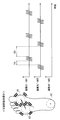
さらに詳記すると、提示面部81a〜83aは、運転者が左足を載置面73に置いたときにそれぞれ踵中心C2、親指の付け根(以下、「母指球中心C1」)及び小指の付け根(以下、「小指球中心C3」)に自然に触れるような位置に配置されている。個別に記載すると、提示面部81aは、載置面73において運転者の母指球中心C1とその周囲(母指球部分)の載置が想定される範囲に設けられている。提示面部82aは、載置面73において踵中心C2とその周囲(踵部分)の載置が想定される範囲に設けられている。提示面部83aは、載置面73において小指球中心C3とその周囲(小指球部分)の載置が想定される範囲に設けられている。まず、図6に基づき、踵中心C2、母指球中心C1及び小指球中心C3の各位置について説明する。
More specifically, the
足裏には、足長FL、踵点HP、第二指先端FT、脛側中足点SFP及び腓側中足点CFPが規定できる。そして、踵点HPと第二指先端FTとを結ぶ仮想線が足軸Afである。また、踵点HPと脛側中足点SFPとの間の距離が内不踏長ILであり、踵点HPと腓側中足点CFPとの距離が外不踏長FILである。さらに、脛側中足点SFPと足軸Afとの距離が半足幅内HWiであり、腓側中足点CFPと足軸Afとの距離が半足幅外HWoである。 The foot length FL, heel point HP, second finger tip FT, shin side midfoot point SFP, and calf side midfoot point CFP can be defined on the sole of the foot. An imaginary line connecting the heel point HP and the second finger tip FT is the foot axis Af. Further, the distance between the heel point HP and the shin side midfoot point SFP is the inner stepless length IL, and the distance between the heel point HP and the calf side middle footpoint CFP is the outer stepless length FIL. Further, the distance between the tibial metatarsal point SFP and the foot axis Af is the half-foot width HWi, and the distance between the calf side metatarsal point CFP and the foot axis Af is the half-foot width HWo.
踵中心C2は、踵点HPから、爪先方向に「足長FL×0.18(L0参照)」となる足軸Af上の位置に規定される。母指球中心C1は、踵点HPから爪先方向に「内不踏長IL」の位置であって、足の内方向に「半足幅内HWi×0.5」の位置である。小指球中心C3は、踵点HPから爪先方向に「外不踏長FIL」の位置であって、足の外方向に「半足幅外×0.5」の位置である。 The heel center C2 is defined at a position on the foot axis Af that is “foot length FL×0.18 (see L0)” in the toe direction from the heel point HP. The center C1 of the ball of the foot is a position of "internal undepressed length IL" in the toe direction from the heel point HP, and a position of "in the half-foot width HWi×0.5" in the inward direction of the foot. The center C3 of the little finger is a position of "outer stepless length FIL" in the toe direction from the heel point HP, and a position of "outer half leg width×0.5" in the outward direction of the foot.
そして、図4及び図6に示すように、フットレスト装置100では、載置面73に左足を自然に置いた状態として、足先を踵点HPに対して外側に僅かに傾けた状態が想定されている。一例として、第一実施形態では、載置面73の長手方向LDに対して足軸Afを外側に8°傾斜させた状態が想定されている。
Then, as shown in FIGS. 4 and 6, in the
提示面部82aは、踵中心C2を加振するよう想定されており、載置面73の長手方向LDの両端のうちで、前端よりも後端に近接した位置に配置されている。そして、踵中心C2が提示面部82aの中心と重なった状態を基準として、提示面部81a,83aの位置が規定されている。
The presenting
母指球中心C1を加振するよう想定された提示面部81aの中心は、提示面部82aの中心から爪先方向にL1の位置であって、足軸Afから足の内方向にL2の位置に配置されている。L1は、内不踏長ILからL0(図6参照)を差し引いた値であって、例えば136.8m程度に規定される。L2は、上述したように半足幅内HWiの半分の値であって、例えば23.1mm程度に規定される。
The center of the
小指球中心C3を加振するよう想定された提示面部83aの中心は、提示面部82aの中心から爪先方向にL3の位置であって、足軸Afから足の外方向にL4の位置に配置されている。L3は、外不踏長FILからL0(図6参照)を差し引いた値であって、例えば112.9m程度に規定される。L4は、上述したように半足幅外HWoの半分の値であって、例えば26.9mm程度に規定される。尚、上記の寸法L1〜L4は、日本皮革産業連合会によって公開された足サイズ計測事業報告書のデータに基づく一例の値である。
The center of the
図5示すように、提示面部81a〜83aの挿通開口74からの突き出し量は、互いに異なっている。車両の前後方向に沿う運転席11の中心線DCL(図1参照)から遠い振動スピーカ83における提示面部83aの突き出し量は、中心線DCLに近い振動スピーカ81における提示面部81aの突き出し量よりも大きくされている。換言すれば、足裏の外側部分の載置が想定される載置面73の外側範囲に設けられた提示面部83aの突き出し量は、足裏の内側部分の載置が想定される載置面73の内側範囲に設けられた提示面部81aの突き出し量よりも大きくされている。加えて、振動スピーカ82における提示面部82aの突き出し量は、他の振動スピーカ81,83における提示面部81a,83aの突き出し量よりも大きくされている。
As shown in FIG. 5, the protrusion amounts of the
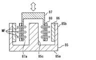
振動スピーカ81〜83は、図5及び図7に示すように、ハウジング84、ヨーク85、振動体87及びアタッチメント89等によって構成されている。ハウジング84は、例えば樹脂材料等によって容器状に形成されている。ハウジング84は、扁平な四角柱状を呈している。ハウジング84は、ヨーク85及び振動体87を収容している。
As shown in FIGS. 5 and 7, the
ヨーク85は、磁性金属材料により、有底の容器状に形成されている。ヨーク85には、底壁85a、外周壁85b及び中心壁85cが形成されている。外周壁85bの内周側には、磁石86が設けられている。磁石86は、外周壁85b、中心壁85c及び底壁85aを巡る磁界MFを形成している。
The
振動体87は、有底の円筒状に形成されている。振動体87の円筒壁87aの外周面には、コイル88が設けられている。コイル88は、ヨーク85及び磁石86によって形成される磁界MFの中に配置されている。コイル88には、駆動装置60の各アンプ62a〜62c(後述する)のいずれかによって駆動信号が印加される。コイル88への駆動信号の印加により、振動体87には軸方向の電磁力が作用する。振動体87は、ヨーク85に対して軸方向に相対変位し、アタッチメント89に応力を作用させる。
The vibrating
アタッチメント89は、ゴム材料等の可撓性を有する材料によって形成されている。アタッチメント89は、ハウジング84に取り付けられており、ハウジング84の開口を塞いでいる。アタッチメント89は、凸状に湾曲した形状となる提示面部81a〜83aを形成している。アタッチメント89の横断面における曲率は、外縁から径方向の中心に向かうに従って徐々に小さくなっている。こうした構成により、各提示面部81a〜83aは、履物の底面(足裏)に中央部分を面接触させる。アタッチメント89の高さは、振動スピーカ81〜83毎に異なっている。各アタッチメント89の高さが異なることにより、各提示面部81a〜83aの挿通開口74からの突き出し量が調整されている。
The
駆動装置60は、図2に示すように、HCU40から入力される制御信号に基づき、フットレスト装置100を作動させる。駆動装置60は、フットレスト装置100の各振動スピーカ81〜83を駆動する構成として、複数(三つ)のデジタル‐アナログ変換器(以下「D/A変換器」)61a〜61cと、複数(三つ)のアンプ62a〜62cとを有している。各振動スピーカ81〜83の各提示面部81a〜83aの振動を個別に制御可能なように、D/A変換器61a〜61c及びアンプ62a〜62cの数は、振動スピーカ81〜83の数と一致している。
As shown in FIG. 2, the
D/A変換器61a〜61cは、デジタル形式の電気信号をアナログ形式の電気信号に変換する電気回路である。D/A変換器61a〜61cは、HCU40及びアンプ62a〜62cと電気的に接続されている。D/A変換器61a〜61cは、HCU40から入力される制御信号をアナログ信号に変換し、アンプ62a〜62cへ向けて出力する。
The D/
アンプ62a〜62cは、入力された信号に比例した電圧又は電流を出力する電気回路である。アンプ62a〜62cはそれぞれ、D/A変換器61a〜61c及び振動スピーカ81〜83と電気的に接続されている。アンプ62a〜62cは、D/A変換器61a〜61cから入力されたアナログ信号を増幅することで、駆動信号を生成する。アンプ62a〜62cは、生成した駆動信号を振動スピーカ81〜83に印加することで、振動スピーカ81〜83を駆動する。
The amplifiers 62a to 62c are electric circuits that output a voltage or a current that is proportional to the input signal. The amplifiers 62a to 62c are electrically connected to the D/
HCU40は、図1及び図2に示すように、車両に搭載された複数の電子制御ユニットのうちの一つである。HCU40は、駆動装置60と電気的に接続されており、駆動装置60と共にフットレスト装置100の作動を制御する。HCU40は、車載ネットワーク30と通信可能に接続されている。HCU40は、車載ネットワーク30を介して、車両システム20から情報を取得する。車両システム20には、車両の自律走行を可能にする電子制御ユニット、車両の状態を検出する種々の車載センサ、及び車両の外部と通信する通信機器等が含まれている。
As shown in FIGS. 1 and 2, the
HCU40の制御回路は、処理部41、記憶部42及びRAM43等を有するコンピュータを主体に構成されている。処理部41は、CPU(Central Processing Unit)、GPU(Graphics Processing Unit)及びFPGA(Field-Programmable Gate Array)等の少なくとも一つを含む構成である。処理部41は、種々の演算処理を実行する。記憶部42は、不揮発性の記憶媒体を含む構成である。記憶部42には、情報提示制御プログラムを含む種々のプログラムが処理部41によって読み取り可能に格納されている。RAM(Random Access Memory)43は、揮発性の半導体メモリである。RAM43は、処理部41による演算処理の作業領域として機能する。
The control circuit of the
HCU40は、記憶部42に格納された情報提示プログラムを処理部41によって実行することで、複数の機能ブロックを構築する。具体的に、HCU40には、フットレスト装置100を制御する機能ブロックとして、情報取得部51、モード遷移制御部52及び信号出力部53等が構築される。
The
情報取得部51は、車両の周囲の地図データ、現在の車速データ及び操舵角データ等、車両に関連する種々の情報を車両システム20から取得する。加えて情報取得部51は、車両の自動運転に関連したシステム(以下、「自動運転システム」)の種々の情報を取得可能である。具体的に、自動運転機能の起動及び停止を示すステータス情報、並びに自動運転機能による自律走行を実現するための走行計画等が、情報取得部51によって取得される。さらに、自動運転システムの状態情報、例えば、GNSSの測位衛星から送信された測位信号の受信感度を示す情報、並びにカメラ及びライダ等の外界センサの検出状態を示すステータス情報等が、情報取得部51によって取得される。
The
モード遷移制御部52は、情報取得部51にて取得された情報に基づき、フットレスト装置100の動作の切り替えを行う。具体的に、モード遷移制御部52は、自動運転のステータス情報に基づき、手動運転から自動運転への切り替え(自動運転ON)に伴い、フットレスト装置100を用いた情報提示を開始する。そして、自動運転から手動運転への切り替え(自動運転OFF)に伴い、フットレスト装置100を用いた情報提示を停止する。
The mode
加えてモード遷移制御部52は、フットレスト装置100の動作モードの切り替えを行う。詳記すると、モード遷移制御部52には、複数の動作モードとして、二つの要請度提示モード、運転行動誘発モード及び先行提示モードが予め設定されている(図8参照)。モード遷移制御部52は、情報取得部51にて取得される情報に基づき、フットレスト装置100の動作モードを遷移させる。尚、手動運転から自動運転に切り替えられた場合に、モード遷移制御部52は、まず要請度提示モードを選択する。
In addition, the mode
要請度提示モードは、自動運転機能から運転者への運転参加の要請度の高低を提示する動作モードであって、自動運転システムの擬似的な鼓動を生成し、提示面部82aの振動によって再現された鼓動を運転者にバイオフィードバックする動作モードである。運転者への運転参加の要請度は、自動運転システムの状態情報に基づき、モード遷移制御部52によって判定される。
The request level presentation mode is an operation mode in which the level of the request level for the driver to participate in the driving from the automatic driving function is presented, and a pseudo heartbeat of the automatic driving system is generated and reproduced by the vibration of the
例えば、GNSSの感度情報及び外界センサのステータス情報に基づき、自動運転システムに余裕のある状態で自動運転が行われている場合には、モード遷移制御部52は、運転参加の要請度を「低」と判定する。一方、GNSSの感度情報及び外界センサのステータス情報に基づき、自動運転の難易度が上昇している場合には、モード遷移制御部52は、運転参加の要請度を「高」と判定する。モード遷移制御部52は、運転参加の要請度の高低に基づき、運転参加の要請度が「低」の要請度提示モードと、運転参加の要請度が「高」の要請度提示モードとを切り替える。
For example, based on the sensitivity information of the GNSS and the status information of the external sensor, when automatic driving is being performed in a state in which the automatic driving system has a margin, the mode
運転行動誘発モードは、自動運転中にて運転行動から離れている運転者に対し、運転行動の開始を促す動作モードである。モード遷移制御部52は、自動運転システムが特定状態となった場合に、要請度提示モードから運転行動誘発モードへと、動作モードを遷移させる。特定状態は、走行計画にて、自動運転機能から運転者への運転交代要求(Take-Over Request)が発生した状態である。一例として、自動運転の許可区間の終了地点が接近した場合に、運転交代要求が発生する。さらに、測位信号の受信感度又は外界センサの検出状態の悪化により、自動運転の継続が困難となった場合でも、運転交代要求が発生する。運転行動誘発モードは、予め規定された誘発動作の終了に伴い、運転行動誘発モードから要請度提示モードへと動作モードを遷移させる。
The driving behavior induction mode is an operation mode that prompts the driver, who is away from the driving behavior during automatic driving, to start the driving behavior. The mode
先行提示モードは、自律走行する車両に挙動変化が発生する以前に、これから発生する挙動変化の内容を運転者に予め通知する動作モードである。モード遷移制御部52は、自律走行する車両の将来挙動を示した走行計画に基づき、運転者に提示すべき挙動変化(以下、「提示挙動変化」)が、例えば数秒後(1〜3秒程度)に車両に生じるか否かを判定する。提示挙動変化の生じるシーン(以下、「先行提示シーン」)は、例えば運転者が不安を感じるような加減速、並びに左右への旋回及びレーンチェンジを行うシーンである。モード遷移制御部52は、先行提示シーンが走行計画にて予定されている場合に、要請度提示モードから先行提示モードへと動作モードを遷移させる。そして、先行提示モードにて、複数の提示面部81a〜83aを用いた提示挙動変化の内容の予告が実施され、当該予告は、車両に挙動変化が発生する以前に終了される。提示挙動変化に対応した将来挙動の提示動作が終了すると、モード遷移制御部52は、先行提示モードから要請度提示モードへと動作モードを遷移させる。
The preceding presentation mode is an operation mode in which the driver is notified in advance of the details of the behavior change that will occur before the behavior change occurs in the autonomously traveling vehicle. The mode
信号出力部53は、フットレスト装置100の作動を制御するための制御信号を生成する。信号出力部53には、各動作モードに対応した制御信号が予め規定されている。信号出力部53は、モード遷移制御部52にて選択された動作モード及び情報取得部51にて取得されている情報に対応する制御信号を生成し、生成した制御信号を駆動装置60へ向けて出力する。
The
ここまで説明したHCU40がフットレスト装置100を用いて実施する情報提示の詳細を、図9〜図18に基づき、図2を参照しつつ、以下説明する。
Details of the information presentation performed by the
図9に示す要請度提示処理は、自動運転の開始に伴う要請度提示モードへの動作モードの遷移により、信号出力部53によって開始される。要請度提示処理は、自動運転が停止されるまで、信号出力部53によって繰り返される。ただし、運転行動誘発モード又は先行提示モードへの遷移期間中にて、信号出力部53は、運転行動誘発モード又は先行提示モードにて規定された振動パターンでの各振動スピーカ81〜83の作動を優先する。
The request degree presenting process shown in FIG. 9 is started by the
S101では、初期設定として、運転参加要請度が「低」である場合のインターバルTin1(図10参照)の設定を記憶部42から取得し、S102に進む。インターバルTin1は、システムの設計時に予め設定された値であってもよく、車両のユーザによって設定された値であってもよい。
In S101, as an initial setting, the setting of the interval Tin1 (see FIG. 10) when the driving participation request degree is “low” is acquired from the
S102では、情報取得部51にて取得される自動運転のステータス情報に基づき、自動運転がオン状態であるか否かを判定する。S102にて自動運転がオフ状態であると判定した場合、S108に進み、振動スピーカ81〜83の作動を停止させる。一方、S102にて、自動運転のオン状態が継続されていると判定した場合、S103に進む。
In S102, based on the status information of the automatic driving acquired by the
S103では、取得した最新のインターバルの設定にて、振動スピーカ82の作動を開始し(図10及び図11参照)、S104に進む。S104では、モード遷移制御部52にて判定された最新の運転参加要請度を取得し、S105に進む。S105では、S104にて取得した運転参加要請度が「高」であるか否かを判定する。S104にて取得した運転参加要請度が「高」である場合、S105からS106に進む。一方、S104にて取得した運転参加要請度が「低」である場合、S105からS107に進む。
In S103, the operation of the
S106では、運転参加要請度が「高」である場合のインターバルTin2(図11参照)の設定を記憶部42から取得し、S102に戻る。この場合のインターバルTin2も、運転参加要請度が「低」である場合と同様に、システムの設計時に予め設定された値であってもよく、車両のユーザによって設定された値であってもよい。一方、S107では、S101と同様に、運転参加要請度が「低」である場合のインターバルTin1(図10参照)の設定を記憶部42から取得し、S102に進む。
In S106, the setting of the interval Tin2 (see FIG. 11) when the driving participation request degree is “high” is acquired from the
以上の要請度提示処理により、運転参加要請度が「低」である場合の要請度提示モードと、運転参加要請度が「高」である場合の要請度提示モードとが、リスクの発生及び消失に起因した自動運転システムの状態変化に応じて切り替えられる。これらの要請度提示モードにおける具体的な振動スピーカ82の制御の詳細を、図10及び図11に基づき説明する。
By the above request degree presentation processing, the risk occurrence and disappearance of the request degree presentation mode when the driving participation request degree is “low” and the request degree presentation mode when the driving participation request degree is “high” It is switched according to the change in the state of the automatic driving system caused by. Details of specific control of the
各要請度提示モードでは、踵部分と接触するよう設けられた振動スピーカ82のみが作動し、足先側の二つの振動スピーカ81,83は、停止状態を維持する。信号出力部53は、振動スピーカ82の振動のオン及びオフを繰り返させる制御により、振動スピーカ82に脈動を生じさせ、自動運転システムの状態を運転者に提示する。脈動は、人間の鼓動を模倣した態様の振動である。振動スピーカ82の振動のオン時間Tonは、運転参加要請度の高低に係らず、実質同一とされる。オン時間Tonにて、駆動装置60から振動スピーカ82には、一つの矩形波が駆動信号として入力される。矩形波の入力による振動スピーカ82の突き上げ振動は、人間の心拍の鼓動に近い感覚を運転者に想起させ得る。
In each request degree presentation mode, only the
一方、振動のインターバルTin1,Tin2は、上述したように運転参加要請度の高低によって変更される。運転参加要請度が「高」である場合のインターバルTin2は、運転参加要請度が「低」である場合のインターバルTin1よりも短く規定される。即ち、運転参加要請度が「高」である場合の振動のオフ時間は、運転参加要請度が「低」である場合のオフ時間よりも短くされる。以上のように、信号出力部53は、システムの状態情報としての運転参加要請度の高低に基づき、要請度が高いほどオフ時間が短く規定されるようにインターバルTin1,Tin2を離散的に変化させ、提示面部82aを脈動させる周期を可変させる。
On the other hand, the vibration intervals Tin1 and Tin2 are changed depending on the level of the driving participation request degree as described above. The interval Tin2 when the driving participation request degree is “high” is defined to be shorter than the interval Tin1 when the driving participation request degree is “low”. That is, the off time of the vibration when the driving participation request degree is “high” is shorter than the off time when the driving participation request degree is “low”. As described above, the
一例として、運転参加要請度が「低」である場合のインターバルTin1による振動は、人間の安静時における心拍数(例えば、毎分60回程度)を基準に設定され、具体的には1ヘルツ程度で繰り返される。一方、運転参加要請度が「高」である場合のインターバルTin2による振動は、人間の上昇時の心拍数(例えば、毎分160回程度)を基準に設定され、具体的には2.6ヘルツ程度で繰り返される。 As an example, the vibration due to the interval Tin1 when the driving participation request degree is “low” is set based on the heart rate of the human at rest (for example, about 60 beats per minute), and specifically, about 1 hertz. Is repeated. On the other hand, the vibration due to the interval Tin2 when the driving participation request degree is “high” is set based on the heart rate (for example, about 160 times per minute) when the person is rising, and specifically, 2.6 Hz. Repeated in degree.
次に、運転行動誘発モードにおける具体的な振動スピーカ81〜83の制御の詳細を、図12に基づき説明する。上述したように、要請度提示モードから運転行動誘発モードへの遷移は、主に自動運転システムからの運転交代要求に基づき実施される。
Next, details of specific control of the
運転行動誘発モードでは、振動させる提示面部81a〜83aの数が要請度提示モードよりも増やされる。具体的に、運転行動誘発モードでは、三つの振動スピーカ81〜83が同期制御され、三つの提示面部81a〜83aにおける振動のオン及びオフのタイミングが同期する。信号出力部59は、全ての振動スピーカ81〜83に、振動のオン及びオフを繰り返させる。駆動信号のうちでオン時間Tonの占める時間割合(オンデューティ比)は、例えば15%程度に設定される。運転行動誘発モードのオン時間Tonにて、各振動スピーカ81〜83に入力される信号波は、立ち上がり時間よりも立ち下がり時間が短い連続した三角波である。
In the driving action inducing mode, the number of vibrating
次に、先行提示モードの詳細を説明する。図13に示す遷移制御処理は、要請度提示処理(図9参照)と同様に自動運転の開始に伴ってHCU40により開始され、要請度提示モード及び先行提示モード間での動作モードの遷移を行う。遷移制御処理は、自動運転が停止されるまで、HCU40によって繰り返される。
Next, details of the preceding presentation mode will be described. The transition control process shown in FIG. 13 is started by the
S111では、自動運転機能にて策定された走行計画を取得し、S112に進む。S112では、S111にて取得した走行計画に基づき、先行提示の要否を判定する。走行計画にて、提示挙動変化が生じる先行提示シーンが数秒後に予定されている場合、S112からS113に進む。S113では、要請度提示モードから先行提示モードへの切り替えにより、フットレスト装置100による先行提示を開始させ、S111に戻る。一方、S112にて先行提示シーンが予定されていないと判定した場合、S112からS114に進む。S114では、先行提示モードから要請度提示モードへの切り替えることにより、先行提示を停止し、S111に戻る。
In S111, the travel plan created by the automatic driving function is acquired, and the process proceeds to S112. In S112, the necessity of prior presentation is determined based on the travel plan acquired in S111. When the preceding presentation scene in which the presentation behavior change occurs is scheduled after a few seconds in the travel plan, the process proceeds from S112 to S113. In S113, the
以上のS113による先行提示モードへの切り替えに基づき、図14に示す先行提示処理が開始される。先行提示処理では、次に予定されている先行提示シーンを判別し、次の車両挙動に対応したアクチュエーションを設定する。 Based on the switching to the preceding presentation mode in S113 described above, the preceding presentation processing shown in FIG. 14 is started. In the preceding presentation process, the next expected preceding scene is determined, and the actuation corresponding to the next vehicle behavior is set.
S121では、車両の前方向に加速閾値を超える加速度が発生予定か否かに基づき、加速動作の提示の要否を判定する。想定される先行提示シーンでの前方向への加速度が加速閾値以下であり、加速動作の提示が不要であると判定した場合、S121からS123に進む。一方で、車両の前方向への加速度が加速閾値を超えると判定した場合、S121からS122に進む。S122では、車両の加速動作を予告する先行提示動作(以下、「加速動作提示」,図15参照)をフットレスト装置100に開始させ、先行提示処理を終了する。
In S121, the necessity of presenting the acceleration operation is determined based on whether or not the acceleration exceeding the acceleration threshold value is planned to occur in the front direction of the vehicle. When the acceleration in the forward direction in the assumed preceding presentation scene is equal to or less than the acceleration threshold and it is determined that the presentation of the acceleration operation is unnecessary, the process proceeds from S121 to S123. On the other hand, when it is determined that the acceleration of the vehicle in the forward direction exceeds the acceleration threshold, the process proceeds from S121 to S122. In S122, the
S123では、車両の後方向に減速閾値を超える加速度が発生予定か否かに基づき、減速動作の提示の要否を判定する。想定される先行提示シーンでの後方向への加速度が減速閾値以下であり、減速動作の提示が不要であると判定した場合、S123からS125に進む。一方で、車両の後方向への加速度が減速閾値を超えると判定した場合、S123からS124に進む。S124では、車両の減速動作を予告する先行提示動作(以下、「減速動作提示」,図16参照)をフットレスト装置100に開始させ、先行提示処理を終了する。
In S123, the necessity of presenting the deceleration operation is determined based on whether or not the acceleration exceeding the deceleration threshold is scheduled to occur in the rearward direction of the vehicle. If the backward acceleration in the assumed preceding presentation scene is equal to or less than the deceleration threshold and it is determined that the deceleration operation is not required to be presented, the process proceeds from S123 to S125. On the other hand, when it is determined that the rearward acceleration of the vehicle exceeds the deceleration threshold value, the process proceeds from S123 to S124. In S124, the
S125では、車両の右方向に旋回閾値を超える加速度が発生予定か否かに基づき、右方向への旋回動作の提示の要否を判定する。想定される先行提示シーンでの右方向の加速度が旋回閾値以下であり、右方向への旋回動作の提示が必要であると判定した場合、S125からS126に進む。S126では、車両の右旋回動作を予告する先行提示動作(以下、「右旋回動作提示」,図17参照)をフットレスト装置100に開始させ、先行提示処理を終了する。
In S125, it is determined whether or not it is necessary to present the turning motion to the right based on whether or not the acceleration exceeding the turning threshold is to be generated in the right direction of the vehicle. If the acceleration in the right direction in the assumed preceding presentation scene is equal to or less than the turning threshold value and it is determined that the turning operation in the right direction needs to be presented, the process proceeds from S125 to S126. In S126, the
一方、S125にて、右方向のへ旋回動作の提示が不要であると判定した場合、S125からS127に進む。S127では、車両の左旋回動作を予告する先行提示動作(以下、「左旋回動作提示」,図18参照)をフットレスト装置100に開始させ、先行提示処理を終了する。
On the other hand, if it is determined in S125 that the presentation of the turning motion to the right is unnecessary, the process proceeds from S125 to S127. In S127, the
以上の先行提示モードにおける各振動スピーカ81〜83の制御の詳細を、図15〜図18に基づき説明する。先行提示モードでは、三つの提示面部81a〜83aのうちで、提示挙動変化によって車両に生じる加速度の方向に沿って並ぶ少なくとも二つが交互に振動するよう制御される。
Details of control of each of the
図15に示す加速動作提示は、車両に前方向への加速度が生じると判定された場合に実施される。加速動作提示では、運転者の足先側であって、車両の前方向に配置された振動スピーカ81,83(以下、前方スピーカ群80f)が一体的に同期制御される。信号出力部59は、運転者の踵側であって、車両の後ろ方向に配置された振動スピーカ82と、上述の前方スピーカ群80fとを、予め規定された時間間隔で交互に振動させる。
The acceleration operation presentation shown in FIG. 15 is performed when it is determined that acceleration in the forward direction occurs in the vehicle. In the acceleration operation presentation, the
詳記すると、振動スピーカ82の振動の停止後から、前方スピーカ群80fの振動開始までの時間間隔が、第一オフ時間T1fである。一方、前方スピーカ群80fの振動の停止後から、振動スピーカ82の振動開始までの時間間隔が、第二オフ時間T2fである。信号出力部59は、第一オフ時間T1fを第二オフ時間T2fよりも短く設定する。こうした各オフ時間T1f,T2fの設定により、一連の振動スピーカ81〜83の振動は、前方向へ押し出されるイメージを運転者に想起させる。
More specifically, the time interval from the stop of the vibration of the
図16に示す減速動作提示は、車両に後方向への加速度が生じると判定された場合に実施される。減速動作提示でも、前方スピーカ群80fは、一体的に同期制御される。信号出力部59は、前方スピーカ群80fと振動スピーカ82と、加速動作提示とは異なる時間間隔で交互に振動させる。
The deceleration operation presentation shown in FIG. 16 is performed when it is determined that the rearward acceleration is generated in the vehicle. Even when the deceleration operation is presented, the
詳記すると、減速動作提示では、前方スピーカ群80fの振動の停止後から、振動スピーカ82の振動開始までの時間間隔が、第一オフ時間T1bとされる。一方、振動スピーカ82の振動の停止後から、前方スピーカ群80fの振動開始までの時間間隔が、第二オフ時間T2bとされる。信号出力部59は、第一オフ時間T1bを第二オフ時間T2bよりも短く設定する。こうした各オフ時間T1b,T2bの設定により、一連の振動スピーカ81〜83の振動は、後方向へ引き戻されるイメージを運転者に想起させる。
More specifically, in the deceleration operation presentation, the time interval from the stop of the vibration of the
尚、加速動作提示及び減速動作提示では、前方スピーカ群80fの振動のオン時間と、振動スピーカ82の振動のオン時間は、実質同一である。加えて、前方スピーカ群80fの振動の強さ(振幅)と、振動スピーカ82の振動の強さ(振幅)も実質的に同一である。
In the acceleration operation presentation and the deceleration operation presentation, the vibration on time of the
図17に示す右旋回動作提示は、車両に右方向への加速度が生じると判定された場合に実施される。右旋回動作提示では、幅方向CDに並ぶ二つの振動スピーカ81,82のみが作動し、踵側の振動スピーカ82は、停止状態を維持する。信号出力部59は、二つの振動スピーカ81,82を、予め規定された時間間隔で交互に振動させる。
The right turn motion presentation shown in FIG. 17 is performed when it is determined that the vehicle will be accelerated to the right. In the right turning motion presentation, only the two
詳記すると、右旋回動作提示では、左側に位置する振動スピーカ83の振動の停止後から、右側に位置する振動スピーカ83の振動開始までの時間間隔が、第一オフ時間T1rとされる。一方、右側に位置する振動スピーカ81の振動の停止後から、左側に位置する振動スピーカ83の振動開始までの時間間隔が、第二オフ時間T2rとされる。信号出力部59は、第一オフ時間T1rを第二オフ時間T2rよりも短く設定する。こうした各オフ時間T1r,T2rの設定により、一連の振動スピーカ81,82の振動は、右方向へ移動するイメージを運転者に想起させる。
In detail, in the right turning motion presentation, the time interval from the stop of the vibration of the
図18に示す左旋回動作提示は、車両に左方向への加速度が生じると判定された場合に実施される。左旋回動作提示でも、信号出力部53は、踵側の振動スピーカ82の停止状態を維持させる一方で、二つの振動スピーカ81,82を予め規定された時間間隔で交互に振動させる。
The left turning motion presentation shown in FIG. 18 is performed when it is determined that the vehicle is to be accelerated to the left. Even when the left turning motion is presented, the
詳記すると、左旋回動作提示では、二つのうちで右側に位置する振動スピーカ81の振動の停止後から、二つのうちで左側に位置する振動スピーカ83の振動開始までの時間間隔が、第一オフ時間T1lとされる。一方、左側に位置する振動スピーカ83の振動の停止後から、右側に位置する振動スピーカ81の振動開始までの時間間隔が、第二オフ時間T2lとされる。信号出力部59は、第一オフ時間T1lを第二オフ時間T2lよりも短く設定する。こうした各オフ時間T1l,T2lの設定により、一連の振動スピーカ81,82の振動は、左方向へ移動するイメージを運転者に想起させる。
Specifically, in the left turning motion presentation, the time interval from the stop of the vibration of the
尚、右旋回動作提示及び左旋回動作提示では、二つの振動スピーカ81,83の振動のオン時間及び強さ(振幅)は、実質同一とされる。さらに、上記の各提示動作にて各振動スピーカ81〜83に入力される信号波は、立ち上がり時間よりも立ち下がり時間が短い連続した三角波である。こうした駆動信号の波形により、足裏を突き上げるような振動が、各提示面部81a〜83aから足裏の各位置に伝搬する。
In the right turning motion presentation and the left turning motion presentation, the on time and the strength (amplitude) of the vibrations of the two
ここまで説明した第一実施形態のように、複数の提示面部81a〜83aの振動を個別に制御すれば、自律走行する車両に将来的に生じる挙動変化の内容が、運転者に通知可能となる。このように振動によって将来挙動を通知可能であれば、フットレスト等を動かすための機構は、省略され得る。したがって、情報提示のための構成の車両への搭載性を確保したうえで、体性感覚を通じたユーザへの挙動変化の通知が可能になる。
If the vibrations of the plurality of
加えて第一実施形態のような振動による情報提示であれば、仮に運転席11に着座した運転者の姿勢が変化し、運転者の体幹に大きなずれが生じた場合でも、フットレストの姿勢を変化させる形態と比較して、情報提示の運転者への伝わり易さは、維持され得る。即ち、振動による情報提示は、フットレストの姿勢変化による情報提示よりも、体幹ずれへの耐性が確保され易い。
In addition, if the information is presented by vibration as in the first embodiment, even if the posture of the driver sitting in the driver's
また第一実施形態では、将来の挙動変化によって車両に加速度が生じる場合、信号出力部53は、複数の提示面部81a〜83aのうちで、発生予定の加速度の方向に沿って並ぶ少なくとも二つを交互に振動させる。こうした制御によれば、フットレスト装置100が簡素な構成であっても、将来の挙動変化によって車両に生じる加速度の向きは、運転者に分かり易く通知され得る。
Further, in the first embodiment, when acceleration occurs in the vehicle due to future behavior change, the
さらに第一実施形態の加速動作提示では、振動スピーカ82の振動停止後から、前方スピーカ群80fの振動開始までの第一オフ時間T1fが、前方スピーカ群80fの振動停止後から振動スピーカ82の振動開始まで第二オフ時間T2fよりも短く規定される。加えて、減速動作提示、右旋回動作提示及び左旋回動作提示のそれぞれにて、各第一オフ時間T1b,T1r,T1lは、各第二オフ時間T2b,T2r,T2lよりも短くされている。以上のように、各振動スピーカ81〜83を交互に振動させつつ、各オフ時間の長さを加速度の方向によって変える制御によれば、車両に発生予定の加速度の前後方向及び左右方向が、運転者にさらに分かり易く通知され得る。
Further, in the acceleration operation presentation of the first embodiment, the first off time T1f from the stop of the vibration of the
加えて第一実施形態では、各提示面部81a〜83aの振動による挙動変化の内容の予告は、車両に挙動変化が発生する以前に終了される。このように、挙動変化の発生以前に、振動スピーカ81〜83の振動による予告が完了されれば、運転者は、予告から挙動変化が開始までのタイミングを感覚的に把握し易くなる。故に、体性感覚を通じた運転者への挙動変化の通知は、運転者にとって分かり易い情報提示となり得る。
In addition, in the first embodiment, the advance notice of the content of the behavior change due to the vibration of each of the
尚、第一実施形態では、HCU40が「情報提示制御装置」に相当し、モード遷移制御部52(S112)が「挙動判定部」に相当し、信号出力部53が「提示制御部」に相当し、走行計画が「挙動情報」に相当する。また、加速動作提示では、提示面部81a,83aが「第一提示面部」に相当し、他方の(残りの)提示面部82aが「第二提示面部」に相当する。一方で、減速動作提示では、提示面部82aが「第一提示面部」に相当し、提示面部81a,83aが「第二提示面部」に相当する。同様に、右旋回動作提示では、提示面部81aが「第一提示面部」に相当し、提示面部83aが「第二提示面部」に相当する一方で、左旋回動作提示では、提示面部83aが「第一提示面部」に相当し、提示面部81aが「第二提示面部」に相当する。
In the first embodiment, the
(第二実施形態)
図19〜図21に示す本開示の第二実施形態は、第一実施形態の変形例である。第二実施形態の要請度提示モード及び先行提示モードでは、各振動スピーカ81〜83の振動パターンが第一実施形態とは異なっている。
(Second embodiment)
The second embodiment of the present disclosure shown in FIGS. 19 to 21 is a modified example of the first embodiment. In the request degree presentation mode and the preceding presentation mode of the second embodiment, the vibration patterns of the
要請度提示モードでは、運転参加の要請度に応じて、振動スピーカ82のインターバルTin1,Tin2に加えて、振幅の大きさも変更される。図19に示すように、運転参加の要請度が「高」である場合の振幅(実線参照)は、運転参加の要請度が「低」である場合の振幅(一点鎖線参照)よりも大きくされる。こうした制御により、運転参加の要請度が上昇した場合に、その旨を運転者にさらに明確に伝えることができる。
In the request level presentation mode, the magnitude of the amplitude is changed in addition to the intervals Tin1 and Tin2 of the
先行提示モードでは、三つの振動スピーカ81〜83の振動が同時に開始される。具体的に、図20に示す右旋回動作提示では、振動スピーカ81の振動を継続させるオン時間Tonrが、振動スピーカ82,83の振動を継続させるオン時間Tonlの二倍程度に設定されている。即ち、信号出力部53(図2参照)は、各振動スピーカ81〜83の振動を開始させた後、振動スピーカ82,83の振動を振動スピーカ81よりも早く停止させる。こうした各オン時間Tonl,Tonrの設定により、一連の振動スピーカ81〜83の振動は、先に停止される振動スピーカ82,83の振動の余韻を利用して、右方向へ移動するイメージを運転者に想起させる。尚、右旋回動作提示として、上記の振動スピーカ81〜83の振動パターンが、所定の時間間隔を開けて複数回繰り返されてもよい。
In the preceding presentation mode, the vibrations of the three vibrating
図21に示す左旋回動作提示では、振動スピーカ83の振動を継続させるオン時間Tonlが、振動スピーカ81,82の振動を継続させるオン時間Tonrの二倍程度に設定されている。即ち、信号出力部53(図2参照)は、各振動スピーカ81〜83の振動を開始させた後、振動スピーカ81,82の振動を振動スピーカ83よりも早く停止させる。こうした各オン時間Tonr,Tonlの設定により、一連の振動スピーカ81〜83の振動は、先に停止される振動スピーカ81,82の振動の余韻を利用して、左方向へ移動するイメージを運転者に想起させる。尚、左旋回動作提示として、上記の振動スピーカ81〜83の振動パターンが、所定の時間間隔を開けて複数回繰り返されてもよい。
In the left turning motion presentation shown in FIG. 21, the on-time Tonl for continuing the vibration of the vibrating
さらに、加速動作提示では、各振動スピーカ81〜83の振動が同時に開始された後、振動スピーカ82の振動が、前方スピーカ群80fよりも早く停止される。同様に、減速動作提示では、各振動スピーカ81〜83の振動が同時に開始された後、前方スピーカ群80fの振動が、振動スピーカ82よりも早く停止される。このような制御でも、先に停止される振動スピーカ81〜83の振動の余韻を利用して、前方向又は後方向へ移動するイメージが、運転者に想起され得る。
Further, in the acceleration operation presentation, after the vibrations of the
ここまで説明した第二実施形態の先行提示モードのように、振動を停止させた振動スピーカ81〜83の余韻を利用した提示方法であっても、第一実施形態と同様に、運転者への挙動変化の内容は、高い確実性をもって通知可能となる。
Even in the presentation method using the afterglow of the
(第三実施形態)
図22及び図23に示す本開示の第三実施形態は、第二実施形態の変形例である。第三実施形態の右旋回動作提示及び左旋回動作提示では、振動スピーカ81,83のみが振動し、振動スピーカ82は、停止状態を維持する。具体的に、図22に示す右旋回動作提示では、振動スピーカ81の振動を継続させるオン時間Tonrが、振動スピーカ83の振動を継続させるオン時間Tonlの二倍程度に設定されている。即ち、信号出力部53(図2参照)は、提示面部81a及び提示面部83aの両方の振動を同時に開始させた後、提示面部83aの振動を提示面部81aよりも早く停止させる。以上により、先に停止された提示面部83aの振動の余韻と、継続された提示面部81aの振動との対比から、右方向へ移動するイメージが運転者に想起され得る。
(Third embodiment)
The third embodiment of the present disclosure shown in FIGS. 22 and 23 is a modification of the second embodiment. In the right turning motion presentation and the left turning motion presentation of the third embodiment, only the vibrating
一方、図23に示す左旋回動作提示では、振動スピーカ83の振動を継続させるオン時間Tonlが、振動スピーカ81の振動を継続させるオン時間Tonrの二倍程度に設定されている。即ち、信号出力部53(図2参照)は、提示面部83a及び提示面部81aの両方の振動を同時に開始させた後、提示面部81aの振動を提示面部83aよりも早く停止させる。以上により、先に停止された提示面部81aの振動の余韻と、継続された提示面部83aの振動との対比から、左方向へ移動するイメージが運転者に想起され得る。
On the other hand, in the left turning motion presentation shown in FIG. 23, the on-time Tonl for continuing the vibration of the vibrating
以上の第三実施形態の先行提示モードでも、第二実施形態と同様に、振動を停止させた振動スピーカ81〜83の余韻を利用することで、体性感覚を通じたユーザへの挙動変化の内容の通知が可能になる。尚、右旋回動作提示及び左旋回動作提示として、上記の振動スピーカ81,83の振動パターンが、所定の時間間隔を開けて複数回繰り返されてもよい。また、第三実施形態における加速動作提示及び減速動作提示は、第二実施形態と実質同一であってよい。
Also in the preceding presentation mode of the third embodiment described above, similar to the second embodiment, by utilizing the afterglow of the
(他の実施形態)
以上、本開示の複数の実施形態について説明したが、本開示は、上記実施形態に限定して解釈されるものではなく、本開示の要旨を逸脱しない範囲内において種々の実施形態及び組み合わせに適用することができる。
(Other embodiments)
Although a plurality of embodiments of the present disclosure have been described above, the present disclosure should not be construed as being limited to the above embodiments and applied to various embodiments and combinations without departing from the scope of the present disclosure. can do.
上記実施形態の変形例1によるフットレスト装置には、下ベース板に対する各振動スピーカの相対位置を、振動スピーカ毎に調整可能な調整機構が設けられている。調整機構は、下ベース板と各振動スピーカのハウジングとの間に設けられており、載置面と垂直な方向への伸縮により、提示面部の位置を移動させる。調整機能は、上カバー部材に対する提示面部の突き出し量を調整する。こうした調整機構の機能により、運転者に優先的に当てる提示面部が、例えば運転者に提示すべき情報に応じて適宜変更可能となる。尚、調整機構は、各振動スピーカに内蔵されていてもよい。 The footrest device according to the modified example 1 of the above-described embodiment is provided with an adjusting mechanism capable of adjusting the relative position of each vibration speaker with respect to the lower base plate for each vibration speaker. The adjustment mechanism is provided between the lower base plate and the housing of each vibration speaker, and moves the position of the presentation surface portion by expanding and contracting in the direction perpendicular to the mounting surface. The adjusting function adjusts the protrusion amount of the presentation surface portion with respect to the upper cover member. With such a function of the adjusting mechanism, the presentation surface portion that is prioritized to the driver can be appropriately changed according to the information to be presented to the driver, for example. The adjustment mechanism may be built in each vibration speaker.
上記実施形態では、上カバー部材に設けられた挿通開口を通じて、各提示面部が足裏に当接するように、載置面に露出していた。しかし、加振提示器である個々の振動スピーカは、載置面に露出する提示面部を有していなくてもよい。各振動スピーカは、上カバー部材及び下ベース板の間に収容された状態で、載置面上の互に異なる箇所を個別に振動させることができる。換言すれば、載置面にて振動スピーカの振動を足裏に伝搬させるための構成は、載置面を形成する上カバー部材と一体的に設けられていてもよい。 In the above-described embodiment, each presentation surface portion is exposed to the placing surface so as to contact the sole through the insertion opening provided in the upper cover member. However, each vibration speaker, which is a vibration presenter, may not have the presentation surface portion exposed on the mounting surface. Each vibration speaker can individually vibrate different parts on the mounting surface while being housed between the upper cover member and the lower base plate. In other words, the structure for propagating the vibration of the vibration speaker to the sole on the mounting surface may be provided integrally with the upper cover member forming the mounting surface.
上記実施形態のアタッチメントは、凸面状に湾曲した提示面部を形成するような扁平な凸球面状に形成されていた。しかし、アタッチメントの形状は、適宜変更可能である。アタッチメントは、例えば扁平な円錐状又は四角錐状であってもよく、或いは平面状の提示面部を形成する扁平な円柱状であってもよい。加えて、提示面部の表面は、平滑な状態であってもよい。或いは、滑り止めとして機能するような凹凸又は凸パターン等が、提示面部に形成されていてもよい。 The attachment according to the above-described embodiment is formed in a flat convex spherical surface shape that forms a presentation surface portion that is curved in a convex shape. However, the shape of the attachment can be changed as appropriate. The attachment may have, for example, a flat conical shape or a quadrangular pyramid shape, or a flat cylindrical shape that forms a flat presentation surface portion. In addition, the surface of the presentation surface part may be in a smooth state. Alternatively, a concavo-convex pattern or a convex pattern that functions as a slip stopper may be formed on the presentation surface section.
さらに、個々の振動スピーカのサイズ又は形状等の要因により、各提示面部を狙いの位置に配置できない場合、アタッチメントの頂点位置を振動スピーカの中心に対して偏心させる等の形状調整により、加振ポイントの最適化が図られていてもよい。 Furthermore, if each presentation surface cannot be placed at the target position due to factors such as the size or shape of each vibration speaker, the vibration point can be adjusted by adjusting the shape such that the top of the attachment is eccentric to the center of the vibration speaker. May be optimized.
また、挿通開口の内周壁とアタッチメントの外周壁との間には、アタッチメントから上カバー部材への振動の伝搬を防ぐ隙間が確保されていてもよい。又は、振動を伝搬させ難い柔軟な材質が、アタッチメントと挿通開口の内周壁との間に設けられていてもよい。さらに、挿通開口を載置面側又は下ベース面側から塞ぐような鍔状の部位が、アタッチメントの外周に設けられていてもよい。 Further, a gap may be secured between the inner peripheral wall of the insertion opening and the outer peripheral wall of the attachment to prevent vibration from propagating from the attachment to the upper cover member. Alternatively, a flexible material that hardly propagates vibration may be provided between the attachment and the inner peripheral wall of the insertion opening. Further, a collar-shaped portion that closes the insertion opening from the mounting surface side or the lower base surface side may be provided on the outer periphery of the attachment.
上記実施形態では、全ての提示面部が上カバー部材から突き出していた。しかし、少なくとも一部の提示面部は、上カバー部材における底壁部の外表面と面一であってもよい。また、各提示面部の突き出し量は、適宜変更されてよく、母指球部分又は小指球部分が踵部分よりも大きくされていてよい。さらに、各提示面部の突き出し量は、互に実質同一であってもよい。 In the above-mentioned embodiment, all the presentation surface parts were projected from the upper cover member. However, at least a part of the presentation surface portion may be flush with the outer surface of the bottom wall portion of the upper cover member. Further, the amount of protrusion of each presentation surface portion may be changed as appropriate, and the ball portion of the thumb or the ball portion of the little finger may be larger than the heel portion. Further, the protrusion amounts of the presentation surface portions may be substantially the same as each other.
上記実施形態では、載置面に三つの提示面部が設けられていた。これら三つの提示面部の位置は、適宜変更されてよい。例えば、載置面のうちで上端よりも下端に近い領域をユーザの踵部分の載置が想定される範囲とし、提示面部82a(図4参照)は、この範囲内で適宜位置を変更されてもよい。同様に、載置面のうちで下端よりも上端に近く且つ外端よりも内端に近い領域をユーザの母指球部分の載置が想定される範囲とし、提示面部81a(図4参照)は、この範囲内で適宜位置を変更されてもよい。さらに、載置面のうちで下端よりも上端に近く且つ内端よりも外端に近い領域をユーザの母指球部分の載置が想定される範囲とし、提示面部83a(図4参照)は、この範囲内で適宜位置を変更されてもよい。また載置面の外側範囲に設けられた提示面部83aは、足裏の小指球部分ではなく、土踏まずよりも外側の足刀部分を加振可能な位置に設けられてもよい。
In the above embodiment, the mounting surface is provided with three presentation surface portions. The positions of these three presentation surface portions may be changed appropriately. For example, an area closer to the lower end than the upper end on the placing surface is set as a range in which the user's heel portion is supposed to be placed, and the position of the
さらに、載置面に設けられる提示面部の数は、三つに限定されない。例えば、二つの提示面部のみが、長手方向又は幅方向に沿って並ぶ配置にて、載置面に設けられていてもよい。或いは、四つ以上の提示面部が、載置面に設けられていてもよい。一例として、母指球中心C1及び小指球中心C3を加振する二つの提示面部に加えて、踵中心C2を幅方向CDに挟んだ両側にて踵部分を加振する二つの提示面部が設けられていてもよい。 Further, the number of presentation surface portions provided on the placement surface is not limited to three. For example, only two presentation surface portions may be provided on the mounting surface in an arrangement that is aligned along the longitudinal direction or the width direction. Alternatively, four or more presentation surface portions may be provided on the placement surface. As an example, in addition to two presentation surface portions that vibrate the ball center C1 and little finger ball center C3, two presentation surface portions that vibrate the heel portion on both sides sandwiching the heel center C2 in the width direction CD are provided. It may be.
上記実施形態にて、長手平板状とされていた載置面の形状は、適宜変更されてよい。例えば載置面は、凸状に湾曲していてもよく、具体的には、長手方向LDに僅かに曲率を有する部分円筒面状であってもよい。さらに、載置面の外形形状は、正方形状、楕円形状及び台形形状等であってもよい。 In the above-described embodiment, the shape of the mounting surface, which has been formed into a long flat plate shape, may be appropriately changed. For example, the placement surface may be curved in a convex shape, and specifically, may be a partially cylindrical surface shape having a slight curvature in the longitudinal direction LD. Furthermore, the outer shape of the mounting surface may be a square shape, an elliptical shape, a trapezoidal shape, or the like.
上記実施形態のフットレスト装置は、車両の前後方向にのみ傾斜した姿勢で取付部に取り付けられていた。換言すれば、載置面73の幅方向CDは、車両の水平方向に沿っていた。しかし、フットレスト装置の取り付け姿勢は、適宜変更されてよい。例えば、幅方向CDを車両の水平方向に対して僅かに傾斜させる取り付けにより、載置面73を外側(センタートンネル側)に向けさせても良い。こうした取り付け姿勢であれば、載置面の外側範囲に設けられた提示面部83a(図4参照)と載置面の内側範囲に設けられた提示面部81a(図4参照)の突き出し量が実質同一とされてもよい。
The footrest device according to the above-described embodiment is attached to the attachment portion in a posture inclined only in the front-rear direction of the vehicle. In other words, the width direction CD of the mounting
上記実施形態では、右ハンドルの車両にてセンタートンネルに隣接した位置に設けられるフットレスト装置の詳細を説明したが、このフットレスト装置は、左ハンドルの車両にてホールハウスの後方に設定されていてもよい。即ち、実質同一の構成であるフットレスト装置が、右ハンドルの車両にも左ハンドルの車両にも適用可能である。 In the above-described embodiment, the details of the footrest device provided in the position adjacent to the center tunnel in the vehicle with the right-hand drive have been described. Good. That is, the footrest device having substantially the same configuration can be applied to both the right-hand drive vehicle and the left-hand drive vehicle.
上記実施形態では、フットレスト装置の載置面に足裏を加振する提示面部が設けられていた。しかし、提示面部を設ける構成は、フットレスト装置に限定されない。例えば、アクセルペダル12(図1参照)、ブレーキペダル13(図1参照)又はクラッチペダル等の踏面を「載置面」とし、これらペダルの踏面に提示面部が設けられてもよい。さらに、運転席11の前方のフロア面14(図1参照)を載置面として、このフロア面14に提示面部が設けられてもよい。尚、自律走行中におけるアクセルペダル12は、運転者による踏力の印加によってストロークしないよう、特定の位置でロックされていてもよい。
In the above-described embodiment, the placement surface of the footrest device is provided with the presentation surface portion that vibrates the sole of the foot. However, the configuration in which the presentation surface portion is provided is not limited to the footrest device. For example, the tread surface of the accelerator pedal 12 (see FIG. 1), the brake pedal 13 (see FIG. 1), the clutch pedal, or the like may be a “mounting surface”, and the presentation surface portion may be provided on the tread surface of these pedals. Further, the floor surface 14 (see FIG. 1) in front of the driver's
さらにHCUによって制御される提示面部は、運転者の足裏を加振する構成に限定されない。提示面部は、車両のユーザに接触可能であれば、車室内のどの位置に設けられていてもよい。例えば、HCUは、運転席11(図1参照)のシート座面、バックレスト及びアームレスト等に設けられた複数の提示面部の振動を個別に制御することにより、車両の将来挙動を運転者に通知してもよい。 Further, the presentation surface section controlled by the HCU is not limited to the configuration that vibrates the sole of the driver. The presentation surface portion may be provided at any position in the vehicle compartment as long as it can contact the user of the vehicle. For example, the HCU notifies the driver of future behavior of the vehicle by individually controlling vibrations of a plurality of presentation surface portions provided on the seat seat surface of the driver's seat 11 (see FIG. 1), the backrest, the armrest, and the like. You may.
上記実施形態では、振動スピーカが加振提示器として用いられていた。こうした振動スピーカに入力される駆動信号の波形は、適宜変更されてよい。また加振提示器は、振動スピーカに限定されない。例えば、回転中心から重心を偏心させた質量体の回転によって振動を発生させる振動モータ等が、加振提示器として用いられていてもよい。或いは、複数の提示面部の一部が振動スピーカによって形成され、他の一部が振動モータによって形成されていてもよい。 In the above embodiment, the vibration speaker is used as the vibration presenter. The waveform of the drive signal input to such a vibration speaker may be changed appropriately. Further, the vibration presenter is not limited to the vibration speaker. For example, a vibration motor or the like that generates vibration by rotation of a mass body whose center of gravity is eccentric from the center of rotation may be used as the vibration presenter. Alternatively, a part of the plurality of presentation surface portions may be formed by the vibration speaker and the other part may be formed by the vibration motor.
尚、振動スピーカにおける加振の立ち上がり及び立ち下がりの時間は、振動モータよりも短縮可能である。加えて、振動の周波数及び振幅の制御も、振動スピーカは、振動モータよりも容易である。加えて、加振スピーカは、載置面に対して垂直な方向の振動を発生させる。そのため、振動スピーカは、足裏の一部分を局所的に加振することができ、運転者による加振箇所の識別を容易にさせることができる。以上の理由から、加振提示器として、振動スピーカは、好適な構成となる。 It should be noted that the rising and falling times of vibration in the vibration speaker can be shorter than those in the vibration motor. In addition, controlling the frequency and amplitude of vibration is also easier with a vibrating speaker than a vibrating motor. In addition, the vibrating speaker generates vibration in a direction perpendicular to the mounting surface. Therefore, the vibration speaker can locally vibrate a part of the sole of the foot, and the driver can easily identify the vibrating portion. For the above reasons, the vibration speaker has a suitable configuration as the vibration presenter.
上記第一実施形態の変形例2のモード遷移制御部52(図2参照)による運転参加の要請度の判定結果は、「高」及び「低」等の離散的な値ではなく、連続的な値として出力される。そして、信号出力部53(図2参照)は、運転参加の要請度の値に基づき、オフ時間を連続的に変化させる。詳記すると、信号出力部53は、運転参加の要請度が高くなるに従って振動のインターバルを漸減させ、運転参加の要請度が低くなるに従って振動のインターバルを漸増させる。以上のように、要請度提示モードにおけるインターバルの増減は、離散的に実施されなくてもよい。
The determination result of the degree of request for driving participation by the mode transition control unit 52 (see FIG. 2) of Modification 2 of the first embodiment is not a discrete value such as “high” and “low” but continuous. It is output as a value. Then, the signal output unit 53 (see FIG. 2) continuously changes the off time based on the value of the degree of request for driving participation. More specifically, the
上記第一実施形態の要請度提示モードでは、踵部分に配置された振動スピーカ82(図10参照)のみが運転者の足裏を加振していた。しかし、要請度提示モードにて鼓動を再現する振動スピーカは、踵部分に配置された振動スピーカ82だけでなくてもよい。他の振動スピーカ81,83(図10参照)が、擬似的な鼓動を再現する振動を行ってもよい。さらに、複数の振動スピーカの同期制御により、擬似的なバイオフィードバックが実施されてもよい。
In the request degree presentation mode of the first embodiment, only the vibration speaker 82 (see FIG. 10) arranged on the heel portion vibrates the sole of the driver. However, the vibration speaker that reproduces the heartbeat in the request degree presentation mode is not limited to the
上記実施形態における運転参加の要請度は、測位信号の受信感度及び外界センサの検出状態等の悪化により上昇した。このような運転参加の要請度の上昇は、例えば降雨、降雪及び濃霧等の気象条件の悪化、市街地のビル陰、トンネル、地下及び施設内への進入等に伴って発生する。さらに、車線を区画する区画線がかすれているシーン、及び急カーブへ進入するシーン等でも、運転参加の要請度の上昇が生じ得る。 The degree of request for participation in driving in the above-described embodiment is increased due to deterioration of the reception sensitivity of the positioning signal and the detection state of the external sensor. Such an increase in the degree of request for participation in driving occurs due to deterioration of meteorological conditions such as rainfall, snowfall, and thick fog, entry into urban building shadows, tunnels, underground and facilities. Further, the demand for driving participation may increase even in a scene in which the lane markings that divide the lane are faint, a scene in which a sharp curve is entered, and the like.
上記第一実施形態の運転行動誘発モード(図12参照)では、三つの振動スピーカ81〜83が同期制御されていた。しかし、運転者に強い違和感を付与できれば、例えば三つの振動スピーカ81〜83の振動をランダムに生じさせる制御が実施されてもよい。さらに、第一実施形態にて15%程度とされていたデューティ比は、適宜変更されてよい。例えば、駆動信号にてオン時間Tonの占めるデューティ比は、50%程度に設定されていてもよい。さらに、オン時間Tonのデューティ比は、時間の経過と共に徐々に引き上げられてもよい。
In the driving action induction mode (see FIG. 12) of the first embodiment, the three
上記第一実施形態の変形例3,4の信号出力部53(図2参照)は、加速度の前後方向及び左右方向の区別をより容易にするため、先行提示モードにて交互に振動させる提示面部81a〜83aの振動の強度(振幅)を、異なった値に設定する。具体的に、変形例3の加速動作提示では、提示面部81a,83aの振動の強度が、提示面部82aの振動の強度よりも強くされ、減速動作提示では、提示面部82aの振動の強度が、提示面部81a,83aの振動の強度よりも強くされる。同様に、変形例3の右旋回動作提示では、提示面部81aの振動の強度が、提示面部83aの振動の強度よりも強くされ、左旋回速動作提示では、提示面部83aの振動の強度が、提示面部81aの振動の強度よりも強くされる。
The signal output unit 53 (see FIG. 2) of the modified examples 3 and 4 of the first embodiment is configured to alternately vibrate in the preceding presentation mode in order to make it easier to distinguish the front-rear direction and the left-right direction of acceleration. The vibration intensities (amplitudes) of 81a to 83a are set to different values. Specifically, in the acceleration motion presentation of the modified example 3, the vibration intensity of the
対して、変形例4の加速動作提示では、提示面部82aの振動の強度が、提示面部81a,83aの振動の強度よりも強くされ、減速動作提示では、提示面部81a,83aの振動の強度が、提示面部82aの振動の強度よりも強くされる。同様に、変形例4の右旋回動作提示では、提示面部83aの振動の強度が、提示面部81aの振動の強度よりも強くされ、左旋回速動作提示では、提示面部81aの振動の強度が、提示面部83aの振動の強度よりも強くされる。
On the other hand, in the acceleration motion presentation of the modification 4, the vibration intensity of the
上記第一実施形態での提示挙動変化の内容の予告は、車両に挙動変化が発生するよりも前に完了されていた。しかし、各動作提示の完了タイミングと、挙動変化に伴った加速度の発生開始タイミングとの前後関係は、適宜調整されてよい。例えば、動作提示の継続中に車両の挙動変化が開始されてもよい。この場合、動作提示の完了タイミングは、挙動変化に伴った加速度の発生開始タイミングよりも後になる。さらに、挙動変化に伴った加速度の発生開始タイミングと実質的に同時となるよう、動作提示の完了タイミングが設定されてもよい。 The advance notice of the content of the presentation behavior change in the first embodiment is completed before the behavior change occurs in the vehicle. However, the anteroposterior relationship between the completion timing of each action presentation and the generation start timing of the acceleration accompanying the behavior change may be appropriately adjusted. For example, the behavior change of the vehicle may be started while the motion presentation is continued. In this case, the completion timing of the action presentation is later than the generation start timing of the acceleration accompanying the behavior change. Further, the action presentation completion timing may be set to be substantially the same as the generation start timing of the acceleration accompanying the behavior change.
上記第一実施形態にて説明の各動作提示は、車両の次の挙動として、加速、減速及び旋回のいずれか一つが実施される場合の動作提示であった。しかし、減速しながらの右旋回等、車両の次の挙動として、複合的な挙動を予定される場合が想定され得る。こうした場合、例えば、図24に示すような複合動作提示が実施される。詳記すると、信号出力部は、まず減速動作提示(図10参照)のように前方スピーカ群80f及び振動スピーカ81を(例えば二回ずつ)交互に振動させる。その後、信号出力部は、右旋回動作提示(図17参照)のように振動スピーカ81及び振動スピーカ83を(例えば二回ずつ)交互に振動させる。複合動作提示では、減速動作提示と右旋回動作提示とが複数回繰り返されてもよい。
Each motion presentation described in the first embodiment is a motion presentation when any one of acceleration, deceleration, and turning is performed as the next behavior of the vehicle. However, it may be possible that a complex behavior is planned as the next behavior of the vehicle, such as turning to the right while decelerating. In such a case, for example, the composite action presentation as shown in FIG. 24 is performed. More specifically, the signal output unit first vibrates the
上記実施形態にて用いられる加速閾値、減速閾値及び左右の旋回閾値は、それぞれ異なる値に設定可能である。車両のユーザは、後(減速)方向の加速度よりも、前(加速)方向及び左右方向の加速度の方が不安を感じ易い。故に、減速閾値よりも、加速閾値及び旋回閾値は、低い値に設定されてよい。さらに、次の車両挙動を積極的に先行提示する場合、各閾値は、全体的に低い値に設定されてよい。また、ユーザの煩わしさの低減を優先する場合、各閾値は、全体的に高い値に設定されてよい。これら各閾値は、車両のユーザによって調整可能であってもよい。 The acceleration threshold value, the deceleration threshold value, and the left and right turning threshold values used in the above embodiment can be set to different values. A user of the vehicle is more likely to feel anxiety about the acceleration in the front (acceleration) direction and the lateral direction than the acceleration in the rear (deceleration) direction. Therefore, the acceleration threshold and the turning threshold may be set to values lower than the deceleration threshold. Further, when the next vehicle behavior is positively presented in advance, each threshold may be set to a low value as a whole. Moreover, when giving priority to the reduction of the user's annoyance, each threshold may be set to a high value as a whole. Each of these thresholds may be adjustable by the user of the vehicle.
上記実施形態では、HCU、駆動装置及びフットレスト装置がそれぞれ別の構成として設けられていた。しかし、駆動装置の構成は、HCU又はフットレスト装置と一体的に設けられていてもよい。さらに、フットレスト装置を制御するためのHCUの演算処理は、HCUとは異なる他の制御装置で実行されてもよく、又はフットレスト装置100に設けられた制御回路によって実行されてもよい。
In the above embodiment, the HCU, the drive device, and the footrest device are provided as separate components. However, the drive device may be integrated with the HCU or the footrest device. Further, the calculation processing of the HCU for controlling the footrest device may be executed by another control device different from the HCU, or may be executed by a control circuit provided in the
さらに、種々の非遷移的実体的記憶媒体(non-transitory tangible storage medium)が処理部にて実行される情報提示制御プログラムを格納する記憶部に採用可能である。こうした非遷移的実体的記憶媒体は、フラッシュメモリ、ハードディスク及び光学ディスク等の種々の不揮発性の記憶媒体であってもよく、又はRAM等の揮発性の記憶媒体であってもよい。また上記の記憶媒体は、HCU等の制御装置に設けられた記憶部に限定されず、当該記憶部へのコピー元となる光学ディスク及び汎用コンピュータのハードディスクドライブ等であってもよい。 Furthermore, various non-transitory tangible storage media can be adopted as the storage unit that stores the information presentation control program executed by the processing unit. Such non-transitional tangible storage media may be various non-volatile storage media such as flash memory, hard disks and optical disks, or volatile storage media such as RAM. Further, the storage medium is not limited to the storage unit provided in the control device such as the HCU, and may be an optical disk or a hard disk drive of a general-purpose computer which is a copy source to the storage unit.
40 HCU(情報提示制御装置)、41 処理部、51 情報取得部、52 モード遷移制御部(挙動判定部)、53 信号出力部(提示制御部)、81a〜83a 提示面部、T1f,T1b,T1r,T1l 第一オフ時間、T2f,T2b,T2r,T2l 第二オフ時間 40 HCU (information presentation control unit), 41 processing unit, 51 information acquisition unit, 52 mode transition control unit (behavior determination unit), 53 signal output unit (presentation control unit), 81a to 83a presentation surface unit, T1f, T1b, T1r , T1l first off time, T2f, T2b, T2r, T2l second off time
Claims (8)
自律走行する前記車両の将来挙動を示した挙動情報を取得する情報取得部(51)と、
前記挙動情報に基づき、前記ユーザに提示する挙動変化が前記車両に生じるか否かを判定する挙動判定部(52)と、
前記挙動判定部にて提示すべきと判定された提示挙動変化の発生以前に、複数の前記提示面部の振動を個別に制御し、前記提示挙動変化の内容を前記ユーザに予め通知する提示制御部(53)と、を備え、
前記提示挙動変化によって前記車両に生じる加速度の方向に沿って並ぶ二つの前記提示面部のうち、加速度の方向に位置する一方を第一提示面部とし、他方を第二提示面部とすると、
前記提示制御部は、
前記第二提示面部の振動の停止後から前記第一提示面部の振動を開始するまでの第一オフ時間(T1f,T1b,T1r,T1l)と、前記第一提示面部の振動の停止後から前記第二提示面部の振動を開始するまでの第二オフ時間(T2f,T2b,T2r,T2l)とを規定し、
前記第一オフ時間を前記第二オフ時間よりも短くする情報提示制御装置。 Information presentation that presents information to the user by controlling to vibrate a plurality of presentation surface portions (81a to 83a) provided to present information to the user through the feeling of the soles of the user who rides in a vehicle capable of autonomous driving A control device,
An information acquisition unit (51) for acquiring behavior information indicating future behavior of the vehicle that is autonomously traveling;
A behavior determination unit (52) for determining whether or not a behavior change presented to the user occurs in the vehicle based on the behavior information,
A presentation control unit that individually controls vibrations of the plurality of presentation surface units and notifies the user of the content of the presentation behavior change in advance before the occurrence of the presentation behavior change that is determined to be presented by the behavior determination unit. (53) and ,
Of the two presentation surface portions lined up in the direction of acceleration generated in the vehicle by the change in the presentation behavior, one positioned in the direction of acceleration is the first presentation surface portion, and the other is the second presentation surface portion.
The presentation control unit,
The first off time (T1f, T1b, T1r, T1l) from the stop of the vibration of the second presentation surface portion to the start of the vibration of the first presentation surface portion, and the time after the stop of the vibration of the first presentation surface portion The second off time (T2f, T2b, T2r, T2l) until the vibration of the second presentation surface portion is started is defined,
Information presentation controller the first off-time you shorter than the second off-time.
自律走行する前記車両の将来挙動を示した挙動情報を取得する情報取得部(51)と、
前記挙動情報に基づき、前記ユーザに提示する挙動変化が前記車両に生じるか否かを判定する挙動判定部(52)と、
前記挙動判定部にて提示すべきと判定された提示挙動変化の発生以前に、複数の前記提示面部の振動を個別に制御し、前記提示挙動変化の内容を前記ユーザに予め通知する提示制御部(53)と、を備え、
前記提示挙動変化によって前記車両に生じる加速度の方向に沿って並ぶ二つの前記提示面部のうち、加速度の方向に位置する一方を第一提示面部とし、他方を第二提示面部とすると、
前記提示制御部は、前記第一提示面部及び前記第二提示面部の両方の振動を開始させた後、前記第二提示面部の振動を前記第一提示面部よりも早く停止させる情報提示制御装置。 Information presentation that presents information to the user by controlling to vibrate a plurality of presentation surface portions (81a to 83a) provided to present information to the user through the feeling of the soles of the user who rides in a vehicle capable of autonomous driving A control device,
An information acquisition unit (51) for acquiring behavior information indicating future behavior of the vehicle that is autonomously traveling;
A behavior determination unit (52) for determining whether or not a behavior change presented to the user occurs in the vehicle based on the behavior information,
A presentation control unit that individually controls vibrations of the plurality of presentation surface units and notifies the user of the content of the presentation behavior change in advance before the occurrence of the presentation behavior change that is determined to be presented by the behavior determination unit. (53) and ,
Of the two presentation surface portions lined up in the direction of acceleration generated in the vehicle by the change in the presentation behavior, one positioned in the direction of acceleration is the first presentation surface portion, and the other is the second presentation surface portion.
The presentation control unit, after starting the oscillation of both the first presentation surface and said second presentation surface, said second presentation surface vibrate the first presentation surface stopped so Ru information presentation control unit faster than the ..
少なくとも一つの処理部(41)を、
自律走行する前記車両の将来挙動を示した挙動情報を取得する情報取得部(51)と、
前記挙動情報に基づき、前記ユーザに提示する挙動変化が前記車両に生じるか否かを判定する挙動判定部(52)と、
前記挙動判定部にて提示すべきと判定された提示挙動変化の発生以前に、複数の前記提示面部の振動を個別に制御し、前記提示挙動変化の内容を前記ユーザに予め通知する提示制御部(53)として機能させ、
前記提示挙動変化によって前記車両に生じる加速度の方向に沿って並ぶ二つの前記提示面部のうち、加速度の方向に位置する一方を第一提示面部とし、他方を第二提示面部とすると、
前記提示制御部は、
前記第二提示面部の振動の停止後から前記第一提示面部の振動を開始するまでの第一オフ時間(T1f,T1b,T1r,T1l)と、前記第一提示面部の振動の停止後から前記第二提示面部の振動を開始するまでの第二オフ時間(T2f,T2b,T2r,T2l)とを規定し、
前記第一オフ時間を前記第二オフ時間よりも短くする情報提示制御プログラム。 The control for vibrating the plurality of presentation faces provided so that to present information to the user via the sense of the sole of the user (81a~83a) boarding an automatic driving-vehicle, information for presenting information to the user A presentation control program,
At least one processing unit (41),
An information acquisition unit (51) for acquiring behavior information indicating future behavior of the vehicle that is autonomously traveling;
A behavior determination unit (52) for determining whether or not a behavior change presented to the user occurs in the vehicle based on the behavior information,
A presentation control unit that individually controls vibrations of the plurality of presentation surface units and notifies the user of the content of the presentation behavior change in advance before the occurrence of the presentation behavior change that is determined to be presented by the behavior determination unit. Function as (53) ,
Of the two presentation surface portions lined up in the direction of acceleration generated in the vehicle by the change in the presentation behavior, one positioned in the direction of acceleration is the first presentation surface portion, and the other is the second presentation surface portion.
The presentation control unit,
The first off-time (T1f, T1b, T1r, T1l) from the stop of the vibration of the second presentation surface part to the start of the vibration of the first presentation surface part, and from the stop of the vibration of the first presentation surface part The second off time (T2f, T2b, T2r, T2l) until the vibration of the second presentation surface portion is started is defined,
Wherein the first off-time the second off information presentation control program that shorter than the time.
少なくとも一つの処理部(41)を、
自律走行する前記車両の将来挙動を示した挙動情報を取得する情報取得部(51)と、
前記挙動情報に基づき、前記ユーザに提示する挙動変化が前記車両に生じるか否かを判定する挙動判定部(52)と、
前記挙動判定部にて提示すべきと判定された提示挙動変化の発生以前に、複数の前記提示面部の振動を個別に制御し、前記提示挙動変化の内容を前記ユーザに予め通知する提示制御部(53)として機能させ、
前記提示挙動変化によって前記車両に生じる加速度の方向に沿って並ぶ二つの前記提示面部のうち、加速度の方向に位置する一方を第一提示面部とし、他方を第二提示面部とすると、
前記提示制御部は、前記第一提示面部及び前記第二提示面部の両方の振動を開始させた後、前記第二提示面部の振動を前記第一提示面部よりも早く停止させる情報提示制御プログラム。 The control for vibrating the plurality of presentation faces provided so that to present information to the user via the sense of the sole of the user (81a~83a) boarding an automatic driving-vehicle, information for presenting information to the user A presentation control program,
At least one processing unit (41),
An information acquisition unit (51) for acquiring behavior information indicating future behavior of the vehicle that is autonomously traveling;
A behavior determination unit (52) for determining whether or not a behavior change presented to the user occurs in the vehicle based on the behavior information,
A presentation control unit that individually controls vibrations of the plurality of presentation surface units and notifies the user of the content of the presentation behavior change in advance before the occurrence of the presentation behavior change that is determined to be presented by the behavior determination unit. Function as (53),
Of the two presentation surface portions lined up in the direction of acceleration generated in the vehicle by the change in the presentation behavior, one positioned in the direction of acceleration is the first presentation surface portion, and the other is the second presentation surface portion.
The presentation control unit is configured after the first presentation surface and to start the vibration of both of said second presentation surface, said second presentation surface vibrate the first presentation information presentation control program Ru quickly quenched than surface of ..
Priority Applications (2)
| Application Number | Priority Date | Filing Date | Title |
|---|---|---|---|
| JP2017150912A JP6720939B2 (en) | 2017-08-03 | 2017-08-03 | Information presentation control device and information presentation control program |
| PCT/JP2018/026140 WO2019026574A1 (en) | 2017-08-03 | 2018-07-11 | Information providing control device and information providing control program |
Applications Claiming Priority (1)
| Application Number | Priority Date | Filing Date | Title |
|---|---|---|---|
| JP2017150912A JP6720939B2 (en) | 2017-08-03 | 2017-08-03 | Information presentation control device and information presentation control program |
Publications (3)
| Publication Number | Publication Date |
|---|---|
| JP2019026216A JP2019026216A (en) | 2019-02-21 |
| JP2019026216A5 JP2019026216A5 (en) | 2019-09-05 |
| JP6720939B2 true JP6720939B2 (en) | 2020-07-08 |
Family
ID=65232657
Family Applications (1)
| Application Number | Title | Priority Date | Filing Date |
|---|---|---|---|
| JP2017150912A Expired - Fee Related JP6720939B2 (en) | 2017-08-03 | 2017-08-03 | Information presentation control device and information presentation control program |
Country Status (2)
| Country | Link |
|---|---|
| JP (1) | JP6720939B2 (en) |
| WO (1) | WO2019026574A1 (en) |
Families Citing this family (2)
| Publication number | Priority date | Publication date | Assignee | Title |
|---|---|---|---|---|
| JP2020131892A (en) * | 2019-02-19 | 2020-08-31 | 日本電信電話株式会社 | Information presentation system, and program |
| CN112193157A (en) * | 2020-10-21 | 2021-01-08 | 恒大恒驰新能源汽车研究院(上海)有限公司 | Footrest information reminding device, control method thereof and vehicle-mounted control terminal |
Family Cites Families (3)
| Publication number | Priority date | Publication date | Assignee | Title |
|---|---|---|---|---|
| JP2006119840A (en) * | 2004-10-20 | 2006-05-11 | Hitachi Ltd | Warning device for vehicle |
| JP6314896B2 (en) * | 2015-04-07 | 2018-04-25 | 株式会社Soken | Information provision device |
| JP2017076232A (en) * | 2015-10-14 | 2017-04-20 | トヨタ自動車株式会社 | Vehicle-purposed notification device |
-
2017
- 2017-08-03 JP JP2017150912A patent/JP6720939B2/en not_active Expired - Fee Related
-
2018
- 2018-07-11 WO PCT/JP2018/026140 patent/WO2019026574A1/en active Application Filing
Also Published As
| Publication number | Publication date |
|---|---|
| WO2019026574A1 (en) | 2019-02-07 |
| JP2019026216A (en) | 2019-02-21 |
Similar Documents
| Publication | Publication Date | Title |
|---|---|---|
| WO2017064941A1 (en) | Notification management device and notification management method | |
| JP6409699B2 (en) | Automated driving system | |
| JP6439657B2 (en) | Presentation control apparatus and presentation control method | |
| JP6443403B2 (en) | Vehicle control device | |
| JP6720939B2 (en) | Information presentation control device and information presentation control program | |
| JPWO2011138855A1 (en) | Awakening state maintaining device and awakening state maintaining method | |
| JP2008077631A (en) | Seat, vehicle seat, and information presentation device for vehicle | |
| US8461975B2 (en) | Obstacle position indicating apparatus and system | |
| US10814886B2 (en) | System of optimizing activation degree of occupant of vehicle | |
| JP6972706B2 (en) | Driving assistance devices, methods, and programs | |
| JP6720938B2 (en) | Information presentation control device and information presentation control program | |
| US20230016979A1 (en) | Awakening inducing device and awakening inducing system | |
| JP6856086B2 (en) | Notification management device and notification management program | |
| JP6766791B2 (en) | Status detector, status detection system and status detection program | |
| JP6583199B2 (en) | Driving change control device and driving change control method | |
| WO2019163883A1 (en) | Information presentation device that provides vehicle information to user | |
| JP2019026213A (en) | Information notification apparatus | |
| WO2020170810A1 (en) | Information presentation system and program | |
| JP2019026214A (en) | Information notification apparatus | |
| JPWO2017006564A1 (en) | Haptic sensation presentation apparatus, haptic presentation method, and computer program | |
| JP2004246791A (en) | Alarming method and device for braking automobile | |
| JP2687784B2 (en) | Vehicle seat device | |
| JP2019016028A (en) | Driving support device, driving support method, and driving support program | |
| JP4897128B2 (en) | Driving feeling generating apparatus and driving feeling generating method | |
| JP2017138764A (en) | Method of improving driver's sense of touch, and vibration pad |
Legal Events
| Date | Code | Title | Description |
|---|---|---|---|
| A521 | Request for written amendment filed |
Free format text: JAPANESE INTERMEDIATE CODE: A523 Effective date: 20190725 |
|
| A621 | Written request for application examination |
Free format text: JAPANESE INTERMEDIATE CODE: A621 Effective date: 20190725 |
|
| TRDD | Decision of grant or rejection written | ||
| A01 | Written decision to grant a patent or to grant a registration (utility model) |
Free format text: JAPANESE INTERMEDIATE CODE: A01 Effective date: 20200519 |
|
| A61 | First payment of annual fees (during grant procedure) |
Free format text: JAPANESE INTERMEDIATE CODE: A61 Effective date: 20200601 |
|
| R150 | Certificate of patent or registration of utility model |
Ref document number: 6720939 Country of ref document: JP Free format text: JAPANESE INTERMEDIATE CODE: R150 |
|
| LAPS | Cancellation because of no payment of annual fees |