JP6766791B2 - Status detector, status detection system and status detection program - Google Patents
Status detector, status detection system and status detection program Download PDFInfo
- Publication number
- JP6766791B2 JP6766791B2 JP2017194618A JP2017194618A JP6766791B2 JP 6766791 B2 JP6766791 B2 JP 6766791B2 JP 2017194618 A JP2017194618 A JP 2017194618A JP 2017194618 A JP2017194618 A JP 2017194618A JP 6766791 B2 JP6766791 B2 JP 6766791B2
- Authority
- JP
- Japan
- Prior art keywords
- driver
- state
- detection
- leg
- driving
- Prior art date
- Legal status (The legal status is an assumption and is not a legal conclusion. Google has not performed a legal analysis and makes no representation as to the accuracy of the status listed.)
- Active
Links
Images


Classifications
-
- B—PERFORMING OPERATIONS; TRANSPORTING
- B60—VEHICLES IN GENERAL
- B60W—CONJOINT CONTROL OF VEHICLE SUB-UNITS OF DIFFERENT TYPE OR DIFFERENT FUNCTION; CONTROL SYSTEMS SPECIALLY ADAPTED FOR HYBRID VEHICLES; ROAD VEHICLE DRIVE CONTROL SYSTEMS FOR PURPOSES NOT RELATED TO THE CONTROL OF A PARTICULAR SUB-UNIT
- B60W30/00—Purposes of road vehicle drive control systems not related to the control of a particular sub-unit, e.g. of systems using conjoint control of vehicle sub-units, or advanced driver assistance systems for ensuring comfort, stability and safety or drive control systems for propelling or retarding the vehicle
-
- B—PERFORMING OPERATIONS; TRANSPORTING
- B60—VEHICLES IN GENERAL
- B60W—CONJOINT CONTROL OF VEHICLE SUB-UNITS OF DIFFERENT TYPE OR DIFFERENT FUNCTION; CONTROL SYSTEMS SPECIALLY ADAPTED FOR HYBRID VEHICLES; ROAD VEHICLE DRIVE CONTROL SYSTEMS FOR PURPOSES NOT RELATED TO THE CONTROL OF A PARTICULAR SUB-UNIT
- B60W40/00—Estimation or calculation of non-directly measurable driving parameters for road vehicle drive control systems not related to the control of a particular sub unit, e.g. by using mathematical models
- B60W40/08—Estimation or calculation of non-directly measurable driving parameters for road vehicle drive control systems not related to the control of a particular sub unit, e.g. by using mathematical models related to drivers or passengers
-
- B—PERFORMING OPERATIONS; TRANSPORTING
- B60—VEHICLES IN GENERAL
- B60W—CONJOINT CONTROL OF VEHICLE SUB-UNITS OF DIFFERENT TYPE OR DIFFERENT FUNCTION; CONTROL SYSTEMS SPECIALLY ADAPTED FOR HYBRID VEHICLES; ROAD VEHICLE DRIVE CONTROL SYSTEMS FOR PURPOSES NOT RELATED TO THE CONTROL OF A PARTICULAR SUB-UNIT
- B60W50/00—Details of control systems for road vehicle drive control not related to the control of a particular sub-unit, e.g. process diagnostic or vehicle driver interfaces
- B60W50/08—Interaction between the driver and the control system
-
- G—PHYSICS
- G08—SIGNALLING
- G08G—TRAFFIC CONTROL SYSTEMS
- G08G1/00—Traffic control systems for road vehicles
- G08G1/16—Anti-collision systems
Description
この明細書による開示は、自動運転機能を備える車両において運転者の状態を検出する状態検出の技術に関する。 The disclosure according to this specification relates to a state detection technique for detecting a driver's state in a vehicle having an automatic driving function.
従来、例えば特許文献1には、運転者に代わって運転操作を実施可能な車両制御装置が開示されている。車両制御装置は、ハンドオーバーとして、自動運転の状態から運転者による手動運転への運転交代を実施する。さらに車両制御装置は、運転者が手動運転に復帰できる状態か否かを、例えばステアリングコラムの上面に設けられたドライバモニタカメラ、及びステアリングホールに設けられたタッチセンサ等によって検出する。
Conventionally, for example,
さて、運転操作に不適切な脚の姿勢が取られている場合にも、運転者は、ハンドオーバーによる運転交代に対応困難となる。しかし、特許文献1の車両制御装置では、運転交代に運転者が対応可能か否かは、主に運転者の上半身の状態に基づいて判定される。故に、脚の姿勢が運転操作に不適切であっても、車両制御装置は、運転者が交代要求に対応できないと判定することが難しかった。
By the way, even when the leg posture is inappropriate for the driving operation, it becomes difficult for the driver to cope with the driving change due to the handover. However, in the vehicle control device of
本開示は、運転操作に不適切な脚の姿勢が取られている場合に、運転者が交代要求に対応できなと判定可能な状態検出装置等の提供を目的とする。 An object of the present disclosure is to provide a state detection device or the like capable of determining that a driver cannot respond to a change request when a leg posture inappropriate for a driving operation is taken.
上記目的を達成するため、開示された一つの態様は、運転者に代わって運転操作を実施可能な自動運転機能を備える車両(A)において、運転者の状態を検出する状態検出装置であって、カメラとは異なる構成によって運転者の脚の位置を検出した検出情報を取得する情報取得部(31)と、検出情報の示す運転者の脚の状態に基づき、自動運転機能からの交代要求に基づく運転交代に運転者が対応可能か否かを判定する状態判定部(32)と、を備え、状態判定部は、少なくとも運転者の右脚の足先が運転席(110)の座面(111)よりも下方から検出されている場合には、運転者が運転交代に対応可能であると判定する状態検出装置とされる。
また開示された一つの態様は、運転者に代わって運転操作を実施可能な自動運転機能を備える車両(A)において、運転者の状態を検出する状態検出装置であって、運転者の脚の位置を検出した検出情報を取得する情報取得部(31)と、検出情報の示す運転者の脚の状態に基づき、自動運転機能からの交代要求に基づく運転交代に運転者が対応可能か否かを判定する状態判定部(32)と、を備え、状態判定部は、交代要求の開始から自動運転の継続が不可能になるまでの余裕時間(Ta)が長くなるほど、運転者が運転交代に対応可能であると判定する許容基準を緩和する状態検出装置とされる。
また開示された一つの態様は、運転者に代わって運転操作を実施可能な自動運転機能を備える車両(A)において、運転者の状態を検出する状態検出装置であって、運転者の脚の位置を検出した検出情報を取得する情報取得部(31)と、検出情報の示す運転者の脚の状態に基づき、自動運転機能からの交代要求に基づく運転交代に運転者が対応可能か否かを判定する状態判定部(32)と、を備え、状態判定部は、交代要求の後、運転者が運転交代に対応可能であると判定する許容基準を厳しくする状態検出装置とされる。
In order to achieve the above object, one aspect disclosed is a state detection device that detects a driver's state in a vehicle (A) having an automatic driving function capable of performing a driving operation on behalf of the driver. , The information acquisition unit (31) that acquires the detection information that detects the position of the driver's leg by a configuration different from the camera, and the change request from the automatic driving function based on the state of the driver's leg indicated by the detection information. A state determination unit (32) for determining whether or not the driver can respond to the driving change based on the driving is provided , and the state determination unit includes a seat surface (110) in which at least the tip of the driver's right leg is the driver's seat (110). if it is detected from below 111), the driver are possible is judged to that state detecting device corresponding to the operation replacement.
Further, one aspect disclosed is a state detection device for detecting a driver's state in a vehicle (A) having an automatic driving function capable of performing a driving operation on behalf of the driver, and is a state detection device for a driver's leg. Whether or not the driver can respond to a driving change based on a change request from the automatic driving function based on the information acquisition unit (31) that acquires the detection information that detects the position and the state of the driver's leg indicated by the detection information. The state determination unit (32) is provided, and the state determination unit is such that the driver changes driving as the margin time (Ta) from the start of the change request to the inability to continue the automatic operation becomes longer. It is a state detection device that relaxes the permissible criteria for determining that it can be handled.
Further, one aspect disclosed is a state detection device for detecting a driver's state in a vehicle (A) having an automatic driving function capable of performing a driving operation on behalf of the driver, and is a state detection device for a driver's leg. Whether or not the driver can respond to a driving change based on a change request from the automatic driving function based on the information acquisition unit (31) that acquires the detection information that detects the position and the state of the driver's leg indicated by the detection information. The state determination unit (32) is provided with a state determination unit (32), and the state determination unit is a state detection device that tightens the permissible criteria for determining that the driver can handle the driving change after the change request.
また開示された一つの態様は、運転者に代わって運転操作を実施可能な自動運転機能を備える車両(A)において、運転者の状態を検出する状態検出プログラムであって、少なくとも一つの処理部(41)を、カメラとは異なる構成によって運転者の脚の位置を検出した検出情報を取得する情報取得部(31)、検出情報の示す運転者の脚の状態に基づき、自動運転機能からの交代要求に基づく運転交代に運転者が対応可能か否かを判定する状態判定部(32)、として機能させ、状態判定部は、少なくとも運転者の右脚の足先が運転席(110)の座面(111)よりも下方から検出されている場合には、運転者が運転交代に対応可能であると判定する状態検出プログラムとされる。
また開示された一つの態様は、運転者に代わって運転操作を実施可能な自動運転機能を備える車両(A)において、運転者の状態を検出する状態検出プログラムであって、少なくとも一つの処理部(41)を、運転者の脚の位置を検出した検出情報を取得する情報取得部(31)、検出情報の示す運転者の脚の状態に基づき、自動運転機能からの交代要求に基づく運転交代に運転者が対応可能か否かを判定する状態判定部(32)、として機能させ、状態判定部は、交代要求の開始から自動運転の継続が不可能になるまでの余裕時間(Ta)が長くなるほど、運転者が運転交代に対応可能であると判定する許容基準を緩和する状態検出プログラムとされる。
また開示された一つの態様は、運転者に代わって運転操作を実施可能な自動運転機能を備える車両(A)において、運転者の状態を検出する状態検出プログラムであって、少なくとも一つの処理部(41)を、運転者の脚の位置を検出した検出情報を取得する情報取得部(31)、検出情報の示す運転者の脚の状態に基づき、自動運転機能からの交代要求に基づく運転交代に運転者が対応可能か否かを判定する状態判定部(32)、として機能させ、状態判定部は、交代要求の後、運転者が運転交代に対応可能であると判定する許容基準を厳しくする状態検出プログラムとされる。
Further, one aspect disclosed is a state detection program for detecting a driver's state in a vehicle (A) having an automatic driving function capable of performing a driving operation on behalf of the driver, and at least one processing unit. (41) is an information acquisition unit (31) that acquires detection information that detects the position of the driver's leg by a configuration different from that of the camera, and the automatic driving function based on the state of the driver's leg indicated by the detection information. It functions as a state determination unit (32) that determines whether or not the driver can respond to a driving change based on a change request, and the state determination unit has at least the tip of the driver's right leg in the driver's seat (110). If it is detected from below the seat surface (111), it is a state detection program that determines that the driver can handle the change of driving.
Further, one aspect disclosed is a state detection program for detecting a driver's state in a vehicle (A) having an automatic driving function capable of performing a driving operation on behalf of the driver, and at least one processing unit. (41) is an information acquisition unit (31) that acquires detection information that detects the position of the driver's leg, and a driving change based on a change request from the automatic driving function based on the state of the driver's leg indicated by the detection information. The state determination unit (32) functions as a state determination unit (32) for determining whether or not the driver can respond, and the state determination unit has a margin time (Ta) from the start of the replacement request until the automatic operation cannot be continued. The longer the length, the more relaxed the permissible criteria for determining that the driver can handle the change of driving .
Further, one aspect disclosed is a state detection program for detecting a driver's state in a vehicle (A) having an automatic driving function capable of performing a driving operation on behalf of the driver, and at least one processing unit. (41) is an information acquisition unit (31) that acquires detection information that detects the position of the driver's leg, and a driving change based on a change request from the automatic driving function based on the state of the driver's leg indicated by the detection information. It functions as a state determination unit (32) that determines whether or not the driver can handle the change, and the state determination unit strictly sets the permissible criteria for determining that the driver can handle the change of driving after the change request. It is said to be a state detection program.
この態様では、運転者の脚の位置が検出情報として取得される。そして、交代要求に基づく運転交代に運転者が対応可能か否かは、運転者の脚の状態に基づき判定される。以上によれば、運転操作に不適切な脚の姿勢が取られている場合には、自動運転機能からの交代要求に対応できないと判定することが可能になる。 In this aspect, the position of the driver's leg is acquired as detection information. Then, whether or not the driver can respond to the driving change based on the change request is determined based on the state of the driver's leg. Based on the above, it is possible to determine that it is not possible to respond to the replacement request from the automatic driving function when the leg posture is inappropriate for the driving operation.
尚、上記括弧内の参照番号は、後述する実施形態における具体的な構成との対応関係の一例を示すものにすぎず、技術的範囲を何ら制限するものではない。 The reference numbers in parentheses are merely examples of the correspondence with the specific configuration in the embodiment described later, and do not limit the technical scope at all.
以下、本開示の複数の実施形態を図面に基づいて説明する。尚、各実施形態において対応する構成要素には同一の符号を付すことにより、重複する説明を省略する場合がある。各実施形態において構成の一部分のみを説明している場合、当該構成の他の部分については、先行して説明した他の実施形態の構成を適用することができる。また、各実施形態の説明において明示している構成の組み合わせばかりではなく、特に組み合わせに支障が生じなければ、明示していなくても複数の実施形態の構成同士を部分的に組み合わせることができる。そして、複数の実施形態及び変形例に記述された構成同士の明示されていない組み合わせも、以下の説明によって開示されているものとする。 Hereinafter, a plurality of embodiments of the present disclosure will be described with reference to the drawings. By assigning the same reference numerals to the corresponding components in each embodiment, duplicate description may be omitted. When only a part of the configuration is described in each embodiment, the configuration of the other embodiment described above can be applied to the other parts of the configuration. Further, not only the combination of the configurations specified in the description of each embodiment, but also the configurations of a plurality of embodiments can be partially combined even if the combination is not specified. Further, it is assumed that the unspecified combination of the configurations described in the plurality of embodiments and modifications is also disclosed by the following description.
(第一実施形態)
本開示の第一実施形態による状態検出装置の機能は、図1に示すHCU(HMI(Human Machine Interface)Control Unit)30によって実現されている。HCU30は、車両制御ECU(Electronic Control Unit)80及び自動運転ECU50等の電子制御ユニットと共に車両Aに搭載されている。HCU30、車両制御ECU80及び自動運転ECU50は、直接的又は間接的に互い電気接続されており、相互に通信可能である。車両Aは、車両制御ECU80及び自動運転ECU50の作動により、自動運転機能を備える。
(First Embodiment)
The function of the state detection device according to the first embodiment of the present disclosure is realized by the HCU (HMI (Human Machine Interface) Control Unit) 30 shown in FIG. The HCU 30 is mounted on the vehicle A together with electronic control units such as a vehicle control ECU (Electronic Control Unit) 80 and an
車両制御ECU80は、車両Aに搭載された車載アクチュエータ群91と直接的又は間接的に電気接続されている。車両制御ECU80は、車載アクチュエータ群91の作動を統合的に管理することで、車両Aの挙動を制御する。車載アクチュエータ群91には、例えば電子制御スロットルのスロットルアクチュエータ、インジェクタ、ブレーキアクチュエータ、並びに駆動用及び回生用のモータジェネレータが含まれている。
The vehicle control ECU 80 is directly or indirectly electrically connected to the vehicle-mounted
車両制御ECU80は、処理部、RAM、メモリ装置、及び入出力インターフェース等を有するコンピュータを主体に構成されている。車両制御ECU80は、メモリ装置に記憶された車両制御プログラムを処理部によって実行することにより、車両制御に係る機能ブロックとしてアクチュエータ制御部81を構築する。アクチュエータ制御部81は、運転者の運転操作に基づく操作情報及び自動運転ECU50から取得される自律走行情報の少なくとも一方に基づき、車載アクチュエータ群91へ向けて出力される制御信号を生成する。
The
自動運転ECU50は、自律走行に必要な情報を取得する構成として、GNSS受信器71、地図データベース72及び自律センサ群73等と直接的又は間接的に電気接続されている。
The
GNSS(Global Navigation Satellite System)受信器71は、複数の人工衛星から送信された測位信号を受信可能である。GNSS受信器71は、受信した測位信号を、車両Aの現在位置を特定するための情報として、自動運転ECU50へ向けて逐次出力する。
The GNSS (Global Navigation Satellite System)
地図データベース72は、多数の地図データを格納している記憶装置である。地図データには、各道路の曲率、勾配、及び区間の長さといった構造情報、並びに制限速度及び一方通行といった非一時的な交通規制情報等が含まれている。地図データベース72は、自動運転ECU50からの要求に基づき、車両Aの現在位置の周辺及び進行方向の地図データを自動運転ECU50に提供する。
The
自律センサ群73は、歩行者及び他の車両等の移動物体、さらに路上の落下物、交通信号、ガードレール、縁石、道路標識、道路標示、及び区画線等の静止物体を検出する。自律センサ群73には、例えばカメラユニット、ライダ及びミリ波レーダ等が含まれている。自律センサ群73はそれぞれ、検出した移動物体及び静止物体に係る物体情報を、自動運転ECU50へ向けて逐次出力する。
The
自動運転ECU50は、処理部61、RAM62、メモリ装置63及び入出力インターフェースを有するコンピュータを主体に構成されている。処理部61は、CPU(Central Processing Unit)、GPU(Graphics Processing Unit)及びFPGA(Field-Programmable Gate Array)等の少なくとも一つを含む構成である。処理部61には、AI(Artificial Intelligence)の学習及び推論に特化した専用のプロセッサが設けられていてもよい。
The
自動運転ECU50は、車両制御ECU80との連携によって車両Aの加減速制御及び操舵制御を行うことにより、運転者に代わって車両Aの運転操作を実施可能な自動運転機能を発揮する。自動運転ECU50は、運転操作の制御権の所在が異なる複数の制御モードを切り替える。複数の制御モードには、自動運転機能によって車両Aを自律走行させる自動運転モード、及び運転者の運転操作によって走行する手動運転モードが含まれている(図2参照)。さらに、自動運転モードから手動運転モードへの遷移時に実行される交代要求モード、及び車両Aを自動退避させるためのMRM(Minimum Risk Maneuver)モードが、制御モードには含まれている。
The
自動運転ECU50は、メモリ装置63に記憶された自動運転プログラムを処理部61によって実行可能である。自動運転プログラムには、車両Aを自律走行させるためのプログラム、及び運転交代を制御するためのプログラム等が含まれている。自動運転プログラムに基づき、自動運転ECU50には、自車位置特定部51、環境認識部52、計画生成部53及び自律走行制御部54等が構築される。
The
自車位置特定部51は、GNSS受信器71にて受信された測位信号に基づき、車両Aの現在位置を特定する。自車位置特定部51は、自律センサ群73のカメラユニットから取得する前方領域の画像と、地図データベース72から取得する詳細な地図データとの照合により、車両Aの詳細な現在位置を同定可能である。
The own vehicle
環境認識部52は、自車位置特定部51にて特定された位置情報、地図データベース72から取得した地図データ、及び自律センサ群73から取得した物体情報等を組み合わせることで、車両Aの周囲の走行環境を認識する。環境認識部52は、特に各自律センサの検出範囲内について、各物体情報の統合結果に基づき、車両Aの周囲の物体の形状及び移動状態を認識する。環境認識部52は、認識した周囲の物体の情報と、位置情報及び地図データと組み合わせることで、実際の走行環境を三次元で再現した仮想空間を生成する。
The
計画生成部53は、環境認識部52によって認識された走行環境に基づき、自動運転機能によって車両Aを自律走行させるための走行計画を生成する。走行計画としては、長中期の走行計画と、短期の走行計画とが生成される。長中期の走行計画では、運転者によって設定された目的地に車両Aを向かわせるための経路が規定される。短期の走行計画では、環境認識部52にて生成された車両Aの周囲の仮想空間を用いて、長中期の走行計画に従った走行を実現するための予定走行経路が規定される。具体的に、車線追従及び車線変更のための操舵、速度調整のための加減速、並びに衝突回避のための急制動等の実行が、短期の走行計画に基づいて決定される。
The
ここで、自動運転機能から運転者への運転交代には、システム側から運転者に計画的に制御権を引き渡すハンドオーバーと、緊急性の高い状況で運転者が自らの判断で制御権を取得するオーバーライドとが存在する。計画生成部53は、自動運転モードによる自律走行の継続が不可能な状況の発生を、進行方向の地図データ及び自律センサ群73から取得する情報等に基づき予測する。計画生成部53は、走行計画の策定が困難となり、自動運転の継続が不可能である場合に、ハンドオーバーのスケジュール(以下、「権限移譲計画」)を策定する。
Here, when the automatic driving function is switched to the driver, the system side systematically hands over the control right to the driver, and the driver acquires the control right at his / her own discretion in a highly urgent situation. There is an override to do. The
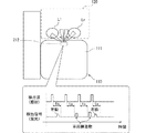
権限移譲計画では、自動運転のオフタイミング(図2 時刻t3)が規定される。そして、オフタイミングから逆算して、自動運転機能から運転者への運転交代を要求する交代要求(以下、「TOR:Take Over Request」)の実施タイミング(図2 時刻t1)が設定される。TORの実施タイミングは、自動運転のオフタイミングに対して、予め規定された余裕時間Ta(例えば4秒,図2参照)だけ早い時刻に設定され、HCU30に通知される。以上のように、計画生成部53は、策定した権限移譲計画に基づき、HCU30と連携して、交代要求モードにおけるハンドオーバーのプロセスを制御する。
In the authority transfer plan, the off-timing of automatic driving (time t3 in FIG. 2) is specified. Then, the execution timing (time t1 in FIG. 2) of the change request (hereinafter, “TOR: Take Over Request”) for requesting the driver to change the driving from the automatic driving function is set by calculating back from the off timing. The execution timing of the TOR is set to a time earlier than the off timing of the automatic operation by a predetermined margin time Ta (for example, 4 seconds, see FIG. 2), and the
自律走行制御部54は、自動運転モードにて、計画生成部53によって策定された予定走行経路に基づく内容の加減速及び操舵を指示する自律走行情報を生成する。自律走行制御部54は、生成した自律走行情報を車両制御ECU80へ向けて逐次出力する。自律走行制御部54は、アクチュエータ制御部81と連携し、予定走行経路に沿って車両Aを自律走行させる。
In the automatic driving mode, the autonomous
HCU30は、運転者への情報提示を統合的に制御する機能と、運転者の状態を検出する機能とを備えた電子制御ユニットである。HCU30は、提示装置20、DSM(Driver Status Monitor)11及び脚センサ12等と直接的又は間接的に電気接続されている。
The
提示装置20は、HCU30によって出力される提示制御信号に基づき、車両Aに係る種々の情報を、運転者を含む車両Aの乗員へ向けて提示する。提示装置20には、例えば表示によって情報を提示する表示装置、通知音及びメッセージ音声等により情報を提示するスピーカ21、及び振動によって情報を提示する触覚刺激装置22等が含まれている。触覚刺激装置22は、例えば運転席110の座面111(図3参照)又は背もたれ等に設けられている。
The presenting
DSM11は、近赤外光源及び近赤外カメラと、これらを制御する制御ユニット等とによって構成されている。DSM11は、近赤外カメラを運転席側に向けた姿勢にて、例えばステアリングコラムの上面に配置される。DSM11は、近赤外光源によって近赤外光を照射された運転者の頭部を近赤外カメラで撮影し、撮像した顔画像の解析によって運転者の状態を監視する。DSM11は、顔画像の解析によって得られた運転者の検出情報を、HCU30へ向けて逐次出力する。
The
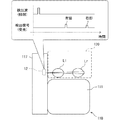
図1,図3及び図4に示す脚センサ12は、例えば光センサであって、光の照射によって物体を検出するアクティブ型の物体検出センサである。脚センサ12は、センターコンソール117の運転席側の側面に設置されている。脚センサ12は、車両Aにおいて、座面111よりも下方であり、且つ、フロア面113よりも運転席110の座面111に近い高さ位置に設置されている。脚センサ12は、検出空間120にある運転者の両脚を個別に検出可能である。検出空間120は、ステアリングホイール115の下方であり、且つ、運転席110の前方に予め規定されている。加えて、車室内にて、検出空間120を区画するドア等の構造物の形状及び材質は、車種毎に異なっている。そのため、検出空間120は、周囲の構造物の形状及び材質を考慮し、車種毎に規定すると好適である。
The
脚センサ12は、投光部13及び受光部14を有している。投光部13は、近赤外線を射出する光源である。投光部13は、HCU30の制御に基づき、検出波としてのパルス状の近赤外線を検出空間120へ向けて発信する。近赤外線は、例えば車両Aの横方向に沿って投光部13からスポット照射される。投光部13は、所定の時間間隔で近赤外線の照射を繰り返す。近赤外光の指向性(照射角)は、脚の太さを超える程度であり、且つ、各ペダル等を誤検出しないような広さに設定される。
The
受光部14は、光信号を電気信号に変換する受光素子である。受光部14は、検出空間120に位置する物体によって反射された近赤外光を検出する。検出空間120に運転者の両脚がある場合、センターコンソール117に近い左脚Llにて反射された近赤外光と、センターコンソール117から遠い右脚Lrにて反射された近赤外光とを、受光部14は順に受光する。受光部14は、受信した光を電気信号に変換し、脚の位置を検出した検出信号として、HCU30に逐次送信する。
The
HCU30は、処理部41、RAM42、メモリ装置43及び入出力インターフェースを有するコンピュータを主体に構成されている。処理部41は、CPU(Central Processing Unit)、GPU(Graphics Processing Unit)及びFPGA(Field-Programmable Gate Array)等の少なくとも一つを含む構成である。処理部41には、AI(Artificial Intelligence)の学習及び推論に特化した専用のプロセッサが設けられていてもよい。
The
HCU30は、DSM11及び脚センサ12等と共に、状態検出システム10を構成している。状態検出システム10は、自動運転モードにおいて、提示装置20による情報提示を制御し、運転者の姿勢を適切な状態に維持する。HCU30は、メモリ装置43に記憶された状態検出プログラムを処理部41によって実行し、運転者の状態検出及び姿勢維持に関連した複数の機能ブロックを構築する。具体的に、HCU30には、情報取得部31、状態判定部32及び報知制御部33等が構築される。
The
情報取得部31は、DSM11にて検出された運転者の検出情報を取得する。加えて情報取得部31は、脚センサ12の作動を制御し、運転者の左右の脚の位置を検出した検出情報を取得する。詳記すると、情報取得部31は、脚センサ12の検出信号に基づき、近赤外光を照射した時刻から、反射された近赤外光を受光した時刻までの差分を計測する。そして、情報取得部31は、時刻の差分から左右の脚の位置を演算し、運転者の両脚の位置を示す検出情報として取得する。
The
さらに情報取得部31は、自動運転ECU50の制御モード等を示すステータス情報を取得する。例えば自動運転のシステム限界の発生予測に基づき、計画生成部53にて権限移譲計画が策定された場合に、情報取得部31は、TORの実施を指示する指令をHCU30から取得する。
Further, the
状態判定部32は、検出情報の示す運転者の上体及び脚の状態に基づき、TORに基づく余裕時間Ta(図2参照)以内での運転交代に運転者が対応可能か否かを判定する。上体の姿勢に問題が無い場合、状態判定部32は、運転者の脚の状態に基づき、運転者の姿勢を「運転姿勢」、「適切姿勢」及び「不適切姿勢」のいずれかに分類する(図5参照)。
The
「運転姿勢」は、手動運転している状態での運転者の姿勢である。右脚Lrの足首よりも先の部分(以下、「右足先」)がアクセルペダル又はブレーキペダルに触れているような状態であれば、状態判定部32は、「運転姿勢」であると判定する。
The "driving posture" is the posture of the driver in the state of manual driving. If the portion of the right leg Lr beyond the ankle (hereinafter, "right foot tip") is in contact with the accelerator pedal or the brake pedal, the
また「適切姿勢」は、余裕時間Ta(図2参照)以内に運転姿勢に復帰可能な姿勢である。対して、「不適切姿勢」は、余裕時間Ta以内に運転姿勢に復帰不可能な姿勢である。換言すると、状態判定部32は、運転者の姿勢を「適切姿勢」に分類した場合に、余裕時間Ta以内での運転交代に運転者が対応できないと判定し、「不適切姿勢」に分類した場合に、余裕時間Ta以内での運転交代に運転者が対応できないと判定する。
The "appropriate posture" is a posture capable of returning to the driving posture within the margin time Ta (see FIG. 2). On the other hand, the "inappropriate posture" is a posture in which the driver cannot return to the driving posture within the margin time Ta. In other words, when the driver's posture is classified as "appropriate posture", the
状態判定部32は、主に運転者の右足先の推定位置に基づき、「適切姿勢」及び「不適切姿勢」を判別する。状態判定部32は、運転者の右足先が座面111よりも下方から検出されており、ペダルの近くに右足先がある場合には、「適切姿勢」であると判定する。運転者の左脚Llの足首よりも先の部分(以下、「左足先」)が座面111よりも下方から検出されていない場合でも、右足先が座面111よりも下方にあれば、状態判定部32は、運転交代に対応可能な「適切姿勢」であると判定する。一方で、状態判定部32は、運転者の左足先が座面111よりも下方から検出されていても、右足先が座面111よりも下方から検出されていない場合には、「不適切姿勢」であると判定する。尚、両脚の足先が共に検出されていない場合には、状態判定部32は、当然に「不適切姿勢」であると判定する。
The
報知制御部33は、情報取得部31にて取得された情報に基づき、提示装置20へ向けて出力する提示制御信号を生成する。報知制御部33は、提示装置20へ向けた提示制御信号の出力により、表示、音及び振動等による情報提示を制御する。報知制御部33は、TORの実施を指示する指令が情報取得部31によって取得された場合、権限移譲計画にて設定された時刻t1(図2参照)にて、運転操作の引き継ぎを運転者に要求する情報提示を、提示装置20を用いて実施する。
The
以上により、TORの通知に気付いた運転者は、周辺状況を確認したうえで、姿勢を正しつつ運転操作を開始する。このとき状態判定部32は、DSM11及び脚センサ12の検出情報に基づき、状態判定部32が「運転姿勢」であると判定する。状態判定部32の判定結果を取得した自動運転ECU50は、時刻t2(図2参照)にて、運転操作可能であると判断し、制御モードを交代要求モードから手動運転モードへと切り替える。
As described above, the driver who notices the TOR notification starts the driving operation while correcting the posture after confirming the surrounding situation. At this time, the
一方で、TORの通知後に運転者が「運転姿勢」をとらないまま余裕時間Ta(図2参照)が経過した場合、自動運転ECU50は、時刻t3(図2参照)にて、制御モードを交代要求モードからMRMモードへと切り替える。その結果、車両Aは、退避走行によって、探索した退避エリアに停車する。
On the other hand, when the spare time Ta (see FIG. 2) elapses without the driver taking the "driving posture" after the notification of TOR, the automatic driving
こうしたMRMモードへの移行を阻止するため、報知制御部33は、自動運転モードにて状態判定部32が「不適切姿勢」と判定した場合に、運転者の状態を「適切姿勢」に戻すためのアクチュエーションを、提示装置20を用いて継続的に実施する(図6参照)。報知制御部33は、例えば運転者が胡座や正座を行っている場合、スピーカ21及び触覚刺激装置22を用いた情報提示により、「適切姿勢」の状態に誘導する。また報知制御部33は、エアバッグの展開に巻き込まれるような位置に運転者の右足先が置かれている場合には、スピーカ21及び触覚刺激装置22を用いた情報提示により、「不適切姿勢」であることを警告し、「適切姿勢」への復帰を促す。このようにして、いつ運転交代が発生してもよいように、TOR前の運転者の状態を維持する。
In order to prevent such a shift to the MRM mode, the
以上のように、運転者に適切姿勢を維持させるため、HCU30によって実施される状態検出処理の詳細を、図7に基づき、図1を参照しつつ説明する。図7に示す状態検出処理は、手動運転モードから自動運転モードへの切り替えに基づき、HCU30によって開始される。
As described above, the details of the state detection process performed by the
S101では、DSM11及び脚センサ12による検出情報を取得し、S102に進む。S102では、直前のS101にて取得した検出情報に基づき、運転者の状態が「適正姿勢」であるか否かを判定する。S101にて、運転者の状態が「適切姿勢」であると判定した場合、S106に進む。一方、S102にて、運転者の状態が「不適切姿勢」であると判定した場合、S103に進む。
In S101, the detection information by the
S103では、S102にて検出された運転者の状態に基づき、「適切姿勢」への復帰を促す誘導又は警告を実施し、S104及びS105に進む。S104及びS105では、S101及びS102と同様に、検出情報に基づき、運転者が「適切姿勢」に復帰したか否かを判定する。S105にて、「適切姿勢」に復帰したと判定した場合、S101に戻り、状態検出処理を継続する。対して、運転者の姿勢が「適切姿勢」に戻らない場合、S103〜S105の処理の繰り返しにより、着座姿勢の修正を促す情報提示が継続される。 In S103, based on the state of the driver detected in S102, guidance or warning prompting the driver to return to the "appropriate posture" is performed, and the process proceeds to S104 and S105. In S104 and S105, similarly to S101 and S102, it is determined whether or not the driver has returned to the "appropriate posture" based on the detection information. If it is determined in S105 that the posture has returned to the "appropriate posture", the posture returns to S101 and the state detection process is continued. On the other hand, when the driver's posture does not return to the "appropriate posture", the information presentation prompting the correction of the sitting posture is continued by repeating the processes of S103 to S105.
一方、S102にて、「適切姿勢」であると判定された場合のS106では、システムの限界予測に基づくTORの通知指示が自動運転ECU50から取得されたか否かを判定する。S106にて、TORの開始が指示されたと判定した場合、TORを実施する処理に移行する。一方で、自動運転モードが継続されると判定した場合、S101に戻り、状態検出処理を継続する。
On the other hand, in S106 when it is determined in S102 that the posture is "appropriate posture", it is determined whether or not the TOR notification instruction based on the limit prediction of the system is acquired from the
尚、「不適切姿勢」のままでシステムの限界予測が発生した場合でも、HCU30は、TORの通知を行う。この場合、HCU30は、TORの通知後、「運転姿勢」への復帰が不可能である旨の判定結果を自動運転ECU50に提供する。この判定結果に基づき、自動運転ECU50は、余裕時間Ta(図2参照)の経過前にMRMモードへの移行を開始する。
The
ここまで説明した第一実施形態では、運転者の脚の位置が検出情報として取得される。そして、TORに基づく運転交代に運転者が対応可能か否かは、運転者の脚の状態に基づき判定される。以上によれば、運転操作に不適切な脚の姿勢が取られている場合には、TORに対応できないとの判定が可能となる。 In the first embodiment described so far, the position of the driver's leg is acquired as detection information. Then, whether or not the driver can respond to the driving change based on the TOR is determined based on the state of the driver's legs. Based on the above, it is possible to determine that TOR cannot be supported when the leg posture is inappropriate for the driving operation.
加えて第一実施形態では、座面111よりも下方から右足先が検出されている場合、状態判定部32は、「適切姿勢」であると判定する。少なくとも右足先が座面111より下方にあれば、運転者は、TORの発生後、余裕時間Ta以内に、アクセルペダル又はブレーキペダルの操作を開始可能である。故に、右足先の位置に依拠してTORに対応可能であると判定すれば、姿勢判定の演算負荷を軽減しつつ、TORに対応不可能な運転者への運転交代の実施が回避される。
In addition, in the first embodiment, when the tip of the right foot is detected from below the
また第一実施形態では、座面111よりも下方に左足先がなくても、右足先さえ座面111よりも下方にあれば、「適切姿勢」と判定される。一般に、ペダル操作は、右足先によって実施される。故に、各ペダルの周囲に左足先がないことに基づき、直ちに「不適切姿勢」と判定する必要はない。以上によれば、運転者が手動運転を開始可能であるにも係わらず、MRMモードへの移行が生じてしまう事態は、回避される。
Further, in the first embodiment, even if the left foot tip is not below the
反対に、座面111よも下方に左足先があっても、右足先が座面111よりも下方にない場合には、「不適切姿勢」と判定される。上述したように、右足先がペダル周辺にない場合、TORに対応した迅速な運転開始は困難となる。故に、右足先が座面111よりも下方にない場合、左足先の位置に係らず運転交代に対応不可能であると判定されることが望ましい。
On the contrary, even if the left foot tip is below the
さらに第一実施形態の脚センサ12は、ステアリングホイール115の下方且つ運転席110の前方に規定された検出空間120にて、運転者の脚を検出する。このように、脚センサ12の検出空間120を限定しても、状態判定部32は、運転者の脚の状態がTORに対応可能な状態か否かを判定できる。故に、運転者の状態判定の精度を確保しつつ、脚センサ12の構成の複雑化が回避できる。
Further, the
加えて上述の検出空間120は、インスツルメントパネル及びステアリングコラム等によって外光が遮られるため、非常に暗い空間となる。故に、近赤外光を発信するアクティブ型の光センサを脚センサ12として用いれば、情報取得部31は、車両Aの周囲の明るさに影響されることなく、検出情報を取得できる。
In addition, the above-mentioned
さらに第一実施形態の状態検出システム10では、脚の状態の検出にカメラが用いられていない。故に、運転者が取る姿勢のパターンと、そのとき撮像される画像データとのマッチングにより、運転者の姿勢を判別する判定器を作成する開発工数が不要になる。さらに、脚の状態の検出にカメラを用いないことで、運転者のプライバシーの問題に配慮した商品性の高い状態検出システム10が実現できる。
Further, in the
また第一実施形態の脚センサ12は、フロア面113よりも座面111に近い高さ位置に設置されている。例えば脚の位置は、膝から遠い位置であって、フロア面113に近い部分ほど、フロア面113に沿って前後左右にばらつき易くなる。一方で、座面111の近い高さであれば、脚(膝)の位置は、大きく変化しない。故に、脚センサ12を座面111に近い高さに配置すれば、近赤外光(検出波)の照射範囲(指向性)を狭めても、検出漏れは生じ難い。故に、脚の位置の検出精度を確保しつつ、脚センサ12の簡素化が可能となる。
Further, the
尚、第一実施形態において、脚センサ12が「位置検出センサ」に相当し、投光部13が「発信部」に相当し、受光部14が「検出部」に相当し、HCU30が「状態検出装置」に相当する。
In the first embodiment, the
(第二実施形態)
図8及び図9に示す第二実施形態は、第一実施形態の変形例である。第二実施形態の脚センサ212は、第一実施形態と同様に光センサであって、第一実施形態とは異なる位置に設置されている。脚センサ212は、運転席110の座面部分の前面であって、フロア面113よりも座面111に近い高さ位置に収容されている。脚センサ212の投光部213は、前方に規定された検出空間120へ向けて近赤外光を照射する。加えて投光部213は、光の照射方向を少なくとも水平方向に走査可能である。投光部213は、光の照射方向を水平方向に旋回させつつ、所定の時間間隔で近赤外線の照射を繰り返す。近赤外光の指向性(照射角)は、脚の太さ程度に絞られている。例えば、近赤外光を左方向へ向けて照射した場合、左脚Llにて反射された近赤外光が受光部214によって検出される。同様に、近赤外光を右方向へ向けて照射した場合、右脚Lrにて反射された近赤外光が受光部214によって検出される。
(Second Embodiment)
The second embodiment shown in FIGS. 8 and 9 is a modification of the first embodiment. The
情報取得部31(図1参照)は、脚センサ212から受信する検出信号に基づき、検出空間120にある運転者の両脚の位置を個別に検出する。詳記すると、情報取得部31は、投光部213による近赤外光の照射方向と、照射時刻から受光時刻までの差分時間と基づき、両脚の位置を推定する。
The information acquisition unit 31 (see FIG. 1) individually detects the positions of both legs of the driver in the
尚、近赤外線の照射時刻から所定時間tsの経過後に検知された反射光は、検出空間120の領域外で車両Aの構造物によって反射された光としてフィルタリングされている。即ち、情報取得部31は、照射時刻から所定時間tsが経過するまでに受光された反射光に基づき、各脚Ll,Lrの有無と位置とを検出する。しかしながら、こうした手法に限らず、ドアに代表される車両Aの構造物は、車種毎に形状や材質が規定されている。故に、反射光の受光時間及び受光強度は、予め既知の値となる。こうしたことから、検出空間120の周囲の構造物に応じた受光時間及び受光強度を予め設定しておき、脚と構造物との区別が実施されてもよい。
The reflected light detected after a lapse of a predetermined time ts from the irradiation time of the near infrared rays is filtered as the light reflected by the structure of the vehicle A outside the region of the
ここまで説明した第二実施形態でも、第一実施形態と同様の効果を奏し、運転操作に不適切な脚の姿勢が取られている場合には、TORに対応できないと判定できる。加えて、検出空間120の後方から近赤外光を照射する構成であれば、車両Aの前後方向に両脚が揃った位置関係であったとしても、情報取得部31は、検出信号に基づき、両脚の位置を把握できる。尚、第二実施形態では、脚センサ212が「位置検出センサ」に相当し、投光部213が「発信部」に相当し、受光部214が「検出部」に相当する。
Even in the second embodiment described so far, the same effect as that of the first embodiment is obtained, and it can be determined that TOR cannot be supported when the leg posture is inappropriate for the driving operation. In addition, if the configuration is such that near-infrared light is emitted from the rear of the
(第三実施形態)
図10〜図12に示す第三実施形態は、第一実施形態の別の変形例である。第三実施形態の状態検出システム310は、第一実施形態と実質同一のHCU30及びDSM11を備えている。加えて状態検出システム310は、運転者の脚を検出する構成として、第一実施形態と実質同一の脚センサ12と、第二実施形態と実質同一の脚センサ212とを有している。
(Third Embodiment)
The third embodiment shown in FIGS. 10 to 12 is another modification of the first embodiment. The
状態検出システム310は、二つの脚センサ12,212を用いて、検出空間120にある運転者の両脚を、異なる方向から検出する。二つの脚センサ12,212は、共にフロア面113よりも座面111に近い高さ位置に設けられている。センターコンソール117に配置された脚センサ12は、車両Aの高さ方向において、運転席110に配置された脚センサ212よりも僅かに高い位置に設置されている(図11参照)。情報取得部31は、二つの脚センサ12,212から出力された検出信号を統合し、検出空間120における各脚Ll,Lrの位置を推定する。
The
ここまで説明した第三実施形態でも、第一実施形態と同様の効果を奏し、運転操作に不適切な脚の姿勢が取られている場合には、TORに対応できないと判定できる。加えて第三実施形態では、二つの脚センサ12,212の検出情報を用いることにより、HCU30は、運転者の両脚の状態をさらに正確に取得し、運転交代可能か否かの適切な判定を行うことができる。尚、第三実施形態では、脚センサ12,212が共に「位置検出センサ」に相当する。
Even in the third embodiment described so far, the same effect as that of the first embodiment is obtained, and it can be determined that TOR cannot be supported when the leg posture is inappropriate for the driving operation. In addition, in the third embodiment, by using the detection information of the two
(第四実施形態)
図13に示す第四実施形態は、第一実施形態のさらに別の変形例である。第四実施形態では、二つの脚センサ412t,412bがセンターコンソール117に設けられている。各脚センサ412t,412bは共に、第一実施形態の脚センサ12(図1参照)と実質同一の構成である。脚センサ412tは、車両の高さ方向において、脚センサ412bよりも高い位置に設けられている。脚センサ412tは、車両の前後方向において、脚センサ412bよりも後方に配置されている。
(Fourth Embodiment)
The fourth embodiment shown in FIG. 13 is still another modification of the first embodiment. In the fourth embodiment, two
以上の構成であれば、情報取得部31(図1参照)は、例えば膝上にて脚組された状態を、二つの脚センサ412t,412bの検出信号から検出可能となる。詳記すると、膝上にて脚組みされた状態では、上方の脚センサ412tは、右脚Lr及び左脚Llを共に検出した検出信号を出力する。一方で、下方の脚センサ412bは、右脚Lrのみを検出した検出信号を出力する。情報取得部31は、こうした二つの検出信号の組み合わせから、運転者の脚組の状態を推定可能となる。
With the above configuration, the information acquisition unit 31 (see FIG. 1) can detect, for example, a state in which the legs are assembled on the knee from the detection signals of the two
ここまで説明した第四実施形態でも、第一実施形態と同様の効果を奏し、運転操作に不適切な脚の姿勢が取られている場合には、TORに対応できないと判定可能になる。加えて第四実施形態では、上下二つの脚センサ412t,412bの検出情報を用いることにより、HCU30は、運転姿勢に復帰困難な脚の状態を適確に把握し、TORに対応できない運転者への運転交代の実施を回避させることができる。尚、第四実施形態では、脚センサ412t,412bが共に「位置検出センサ」に相当する。
Even in the fourth embodiment described so far, the same effect as that of the first embodiment can be obtained, and it can be determined that the TOR cannot be supported when the leg posture is inappropriate for the driving operation. In addition, in the fourth embodiment, by using the detection information of the two upper and
(第五実施形態)
図14及び図15に示す第五実施形態は、第一実施形態のさらに別の変形例である。第五実施形態では、第一実施形態の脚センサ12(図1参照)に替えて、フロアセンサ15が設けられている。フロアセンサ15は、脚センサ12と同様に、ステアリングホイール115の下方且つ運転席110の前方である検出空間120から、運転者の両脚Ll,Lrを検出するセンサである。フロアセンサ15は、シート状に形成されており、フロア面113の裏側に設けられている。フロアセンサ15は、検出空間120の底面全体に間接的に臨むように、検出空間120の底面と同程度の大きさに形成されている。フロアセンサ15は、二次元状に配列された複数の圧力検出部を有している。
(Fifth Embodiment)
The fifth embodiment shown in FIGS. 14 and 15 is still another modification of the first embodiment. In the fifth embodiment, the
圧力検出部は、例えばフロアセンサ15を格子状に区画した各領域(図15 一点鎖線参照)に一つずつ設けられている。個々の圧力検出部は、フロア面113に足裏が置かれたことによる荷重を検知する。フロアセンサ15は、各領域に作用している圧力を、検出信号としてHCU30(図1参照)に逐次出力する。
For example, one pressure detection unit is provided in each region (see the alternate long and short dash line in FIG. 15) in which the
情報取得部31(図1参照)は、フロアセンサ15の各領域に作用している圧力(荷重)を検出する。こうした検出情報に基づき、状態判定部32(図1参照)は、少なくとも二つの領域に閾値以上の圧力が作用している等、検出空間120から両脚Ll,Lrの足跡が検出できている場合には、「適切姿勢」であると判定する。一方で、一つの領域しか閾値以上の圧力が作用していない等、片足の足跡しか検出できない場合、及び閾値以上の圧力がどの領域にも作用しておらず、片足の足跡すら検出できない場合、状態判定部32は、「不適切姿勢」であると判定する。
The information acquisition unit 31 (see FIG. 1) detects the pressure (load) acting on each region of the
ここまで説明した第五実施形態のように、フロアセンサ15を用いて脚を検出する構成であっても、第一実施形態と同様の効果を奏し、運転操作に不適切な脚の姿勢が取られている場合には、TORに対応できないと判定できる。
Even with the configuration of detecting the legs using the
(第六実施形態)
本開示の第六実施形態は、図1及び図2に示す第一実施形態の変形例である。第六実施形態の自動運転ECU50では、権限移譲計画にて設定される余裕時間Taが可変とされている。例えば、車両Aの走行環境が良好(晴天等)であり、自律センサ群73の検出距離が十分に長くなる場合、自動運転ECU50は、遠方の状況を把握し、自動運転のオフタイミングに対し早いタイミングでTORを実施できる。具体的には、10秒程度の余裕時間Taを確保した権限移譲計画が策定可能となる。一方で、車両Aの走行環境が良好ではなく(悪天候や暗所等)、自律センサ群73の検出距離が短くなる場合では、自動運転ECU50は、遠方の状況を把握し難くなる。故に、権限移譲計画にて設定される余裕時間Taは、良好な走行環境である場合と比較して短くなり、例えば4秒程度とされる。
(Sixth Embodiment)
The sixth embodiment of the present disclosure is a modification of the first embodiment shown in FIGS. 1 and 2. In the
以上のような自動運転ECU50及び自律センサ群73の状態に応じて、状態判定部32は、「適切姿勢」と「不適切姿勢」とを区分けする許容基準(図5参照)を、余裕時間Taの長さに合わせて変化させる。即ち、余裕時間Taが長くなれば、許容基準は緩和される。反対に、余裕時間Taが短くなれば、許容基準は厳しくされる。
Depending on the state of the
具体的に、座面上での胡座及び正座、並びに膝上での脚組といった運転者の姿勢は、余裕時間Taが長く(約10秒)確保可能な走行環境では「適切姿勢」と判別され、余裕時間Taが短い(約4秒)走行環境では「不適切姿勢」と判別される。一方で、ステアリングホイール115(図3参照)及び運転席側のドア等に右足先を掛けた姿勢は、余裕時間Taに係らず、「不適切姿勢」と判別される。 Specifically, the posture of the driver such as crossed legs and seiza on the seat surface and legs on the knees is determined to be "appropriate posture" in a driving environment where a long margin time Ta (about 10 seconds) can be secured. In a driving environment where the margin time Ta is short (about 4 seconds), it is determined to be an "inappropriate posture". On the other hand, the posture in which the right foot tip is hung on the steering wheel 115 (see FIG. 3) and the door on the driver's seat side is determined to be an "inappropriate posture" regardless of the margin time Ta.
加えて状態判定部32は、余裕時間Taが長く確保可能な場合に、TORの後、自動運転のオフタイミングまでの残り時間が短くなるに従って、許容基準を厳しくする。例えば、自動運転のオフタイミングまでの残り時間が4秒程度となったタイミングにて、状態判定部32は、座面上での胡座及び正座、並びに膝上での脚組といった姿勢を、「適切姿勢」ではなく、「不適切姿勢」であると判別する。
In addition, the
ここまで説明した第六実施形態でも、第一実施形態と同様の効果を奏し、運転操作に不適切な脚の姿勢が取られている場合には、TORに対応できないとの判定結果が得られる。加えて第六実施形態のように、交代要求モードにて確保可能な余裕時間Taの長さに合わせて、「適切姿勢」と「不適切姿勢」とを切り分ける許容基準は、変更されてよい。こうした制御によれば、自動運転モードにて運転者に許される姿勢が増えるため、姿勢矯正のための不必要な誘導が低減される。以上によれば、運転者等のユーザにとって有益な自動運転機能の提供が可能になる。 Even in the sixth embodiment described so far, the same effect as that of the first embodiment is obtained, and if the leg posture is inappropriate for the driving operation, it is determined that the TOR cannot be supported. .. In addition, as in the sixth embodiment, the permissible standard for separating the "appropriate posture" and the "inappropriate posture" may be changed according to the length of the margin time Ta that can be secured in the shift request mode. According to such control, the posture allowed for the driver in the automatic driving mode is increased, so that unnecessary guidance for posture correction is reduced. Based on the above, it is possible to provide an automatic driving function that is useful for users such as drivers.
さらに第六実施形態のように、TOR後の「適切姿勢」の判定基準を、自動運転のオフタイミングが迫るにつれて引き上げれば、自動運転のオフタイミングまでに正しい運転姿勢への復帰を促す情報提示が実施され得る。 Further, as in the sixth embodiment, if the criterion for "appropriate posture" after TOR is raised as the off-timing of automatic driving approaches, information is presented to encourage the driver to return to the correct driving posture by the off-timing of automatic driving. Can be implemented.
(他の実施形態)
以上、本開示の複数の実施形態について説明したが、本開示は、上記実施形態に限定して解釈されるものではなく、本開示の要旨を逸脱しない範囲内において種々の実施形態及び組み合わせに適用することができる。
(Other embodiments)
Although the plurality of embodiments of the present disclosure have been described above, the present disclosure is not construed as being limited to the above embodiments, and is applied to various embodiments and combinations without departing from the gist of the present disclosure. can do.
上記第六実施形態の変形例1では、権限移譲計画にて設定される余裕時間が、上記第一実施形態等よりも長く、且つ、一定の長さ(例えば10秒)とされている。故に、変形例1では、自動運転モードにおける許容基準の変更は、実施されない。例えば、自律センサ群の検出距離及び精度が十分であれば、こうした設定が可能となる。故に、自動運転モードでは、胡座、正座、及び膝上での脚組といった姿勢が許容される。 In the first modification of the sixth embodiment, the margin time set in the authority transfer plan is longer than that of the first embodiment and the like, and is a fixed length (for example, 10 seconds). Therefore, in the first modification, the change of the allowable standard in the automatic operation mode is not implemented. For example, if the detection distance and accuracy of the autonomous sensor group are sufficient, such a setting is possible. Therefore, in the automatic driving mode, postures such as cross-legged, seiza, and legs on the knees are allowed.
一方で、状態判定部は、第六実施形態と同様に、TORの後に、自動運転のオフタイミングまでの残り時間が短くなるに従って、許容基準を厳しくする。具体的には、自動運転のオフタイミングまでの残り時間が所定の閾値(例えば4秒)未満となったタイミングにて、状態判定部は、胡座、正座、及び膝上での脚組といった姿勢を、「適切姿勢」ではなく、「不適切姿勢」であると判定するようになる。その結果、上記の姿勢を取る運転者に対して、適切なタイミングでの警告が実施される。 On the other hand, as in the sixth embodiment, the state determination unit tightens the permissible standard as the remaining time from the TOR to the off timing of the automatic operation becomes shorter. Specifically, when the remaining time until the off timing of automatic driving becomes less than a predetermined threshold value (for example, 4 seconds), the state determination unit takes a posture such as cross-legged, seiza, and legs on the knee. , It comes to judge that it is "inappropriate posture" instead of "appropriate posture". As a result, a warning is given to the driver who takes the above posture at an appropriate timing.
以上の変形例1のように、余裕時間が可変でなくても、状態判定部は、TOR後等の適切なタイミングで許容基準を変化させてもよい。さらに、余裕時間の具体的な値は、車両が使用される地域の法規及びガイドライン、並びに車両が走行する道路の制限速度等に応じて、適宜変更されて良い。
As in the
上記実施形態では、脚の位置を検出する構成として、光センサ及びフロアセンサ等が採用されていた。しかし、光センサに替えて、ラインセンサ及び超音波センサ等が採用可能である。超音波センサにおいては、検出波として超音波を発振する振動部が「発信部」に相当し、脚によって反射された超音波を受信する受信部が「検出部」に相当する。さらに、これらのセンサに限定されず、種々のアクティブ型及びパッシブ型の物体検出センサが、脚の位置を検出するセンサとして採用可能である。また、脚と構造物とを区別する上述の手法は、超音波センサ等を用いた形態にも適用可能である。 In the above embodiment, an optical sensor, a floor sensor, or the like has been adopted as a configuration for detecting the position of the leg. However, instead of the optical sensor, a line sensor, an ultrasonic sensor, or the like can be adopted. In the ultrasonic sensor, the vibrating unit that oscillates ultrasonic waves as a detection wave corresponds to the "transmitting unit", and the receiving unit that receives the ultrasonic waves reflected by the legs corresponds to the "detecting unit". Further, not limited to these sensors, various active and passive object detection sensors can be adopted as sensors for detecting the position of the legs. Further, the above-mentioned method for distinguishing a leg from a structure can also be applied to a form using an ultrasonic sensor or the like.
さらに詳記すると、状態検出システムに設けられるセンサは、図16に示すドットの範囲の姿勢を検出可能であることが望ましい。図16では、ペダル操作に直結する運転者の右脚の姿勢が、股関節の角度θh及び膝関節の角度θbによって規定されており、各関節の角度θh,θbを変えた場合の運転者の姿勢が一覧で示されている。そして、ドットの範囲は、正しい運転姿勢に戻すまでに体軸の変更が不要な姿勢の範囲となっている。 More specifically, it is desirable that the sensor provided in the state detection system can detect the posture in the range of the dots shown in FIG. In FIG. 16, the posture of the driver's right leg, which is directly connected to the pedal operation, is defined by the hip joint angle θh and the knee joint angle θb, and the driver's posture when the joint angles θh and θb are changed. Is listed. The range of the dots is the range of the posture that does not require the change of the body axis until the correct driving posture is returned.
例えば、膝下での脚組は、運転姿勢に戻すのに体軸の変更が不要であるため、「適切姿勢」に区分けされる。一方で、右脚を伸ばすことで、右側のドア又はウィンドウ、或いはステアリングホイール115に掛けていた場合、運転姿勢への復帰に体軸の変更が必要となる。同様に、膝上で脚組されていた場合も、体軸の変更が必要となる。故に、これらの姿勢は、「不適切姿勢」に区分けされる。
For example, the legs below the knee are classified into the "appropriate posture" because it is not necessary to change the body axis to return to the driving posture. On the other hand, when the right leg is extended and hung on the right door or window or the
上記実施形態では、簡単な構成で上記の判別を行うために、脚センサの検出に基づく右脚の状態から「適切姿勢」及び「不適切姿勢」が判定されていた。しかし、例えば運転者の前上方に設けた車内カメラの検出情報を脚センサの検出情報に組み合わせれば、右脚を前方に投げ出した上記のような姿勢が特定可能となる。そのため、上体と脚の各検出結果を組み合わせて運転者の状態を検出する状態検出システムであれば、精度の高い注意喚起の実施が可能になる。 In the above embodiment, the "appropriate posture" and the "inappropriate posture" are determined from the state of the right leg based on the detection of the leg sensor in order to perform the above determination with a simple configuration. However, for example, by combining the detection information of the in-vehicle camera provided above the front of the driver with the detection information of the leg sensor, the above-mentioned posture in which the right leg is thrown forward can be specified. Therefore, if it is a state detection system that detects the state of the driver by combining the detection results of the upper body and the legs, it is possible to carry out highly accurate alerting.
また、位置検出センサによる検出空間の範囲も、適宜変更されてよい。例えば、座面上に位置する運転者の股関節の状態が検出されてもよい。こうした検出空間の設定範囲に合わせて、位置検出センサの位置も変更可能である。例えば、位置検出センサは、センタークラスタの側面、ステアリングコラムの下面、及びペダルの近傍等に設置されてよい。 Further, the range of the detection space by the position detection sensor may be changed as appropriate. For example, the state of the driver's hip joint located on the seat surface may be detected. The position of the position detection sensor can also be changed according to the setting range of the detection space. For example, the position detection sensor may be installed on the side surface of the center cluster, the lower surface of the steering column, the vicinity of the pedal, and the like.
さらに、運転者の上体の様子を監視する構成は、DSMに限定されない。状態検出システムは、DSMと共に、又はDSMに替えて、例えばステアリングホイール115(図3参照)の把持を検知する静電センサ又は圧力センサ、或いは上述の車内カメラ等を、備えていてもよい。さらに、DSM等の構成は、状態検出システムから省略されてもよい。 Further, the configuration for monitoring the state of the driver's upper body is not limited to DSM. The state detection system may include, for example, an electrostatic sensor or a pressure sensor for detecting the grip of the steering wheel 115 (see FIG. 3), an in-vehicle camera described above, or the like, together with or in place of the DSM. Further, the configuration such as DSM may be omitted from the state detection system.
上記実施形態の自動運転ECUは、走行環境のモニタリングを運転者に代わって担う、所謂アイオフの自動運転を可能にしていた。本開示による運転者の状態検出方法は、こうしたレベル3の自動運転が実施されている期間での運転者の姿勢検出に好適となる。加えて、本開示による状態検出方法は、走行環境のモニタリングが運転者によって行われるレベル2の自動運転にも適用可能である。
The automatic driving ECU of the above-described embodiment enables so-called eye-off automatic driving, which is responsible for monitoring the driving environment on behalf of the driver. The driver's state detection method according to the present disclosure is suitable for detecting the posture of the driver during the period during which
そして、状態検出装置の機能は、上記のHCUとは異なるハードウェア構成及びソフトウェア構成によって実現されてもよい。例えば、自動運転ECU及びHCUを一体的に構成した電子制御ユニットの処理部が、上述した状態検出方法を実施してもよい。或いは、HCU、自動運転ECU及び車両制御ECUを含む複数の電子制御装置が、本開示による状態検出プログラムを分散処理してもよい。 Then, the function of the state detection device may be realized by a hardware configuration and a software configuration different from the above-mentioned HCU. For example, the processing unit of the electronic control unit that integrally configures the automatic operation ECU and the HCU may carry out the above-mentioned state detection method. Alternatively, a plurality of electronic control devices including the HCU, the automatic driving ECU, and the vehicle control ECU may perform distributed processing of the state detection program according to the present disclosure.
さらに、フラッシュメモリ及びハードディスク等の種々の非遷移的実体的記憶媒体(non-transitory tangible storage medium)が状態検出プログラムを格納する構成として、HCU等のメモリ装置に採用可能である。加えて、状態検出プログラムを記憶する記憶媒体は、車載された電子制御ユニットに設けられた記憶媒体に限定されず、当該記憶媒体へのコピー元となる光学ディスク及び汎用コンピュータのハードディスクドライブ等であってもよい。 Further, various non-transitory tangible storage media such as a flash memory and a hard disk can be adopted in a memory device such as an HCU as a configuration for storing a state detection program. In addition, the storage medium for storing the state detection program is not limited to the storage medium provided in the electronic control unit mounted on the vehicle, and may be an optical disk as a copy source to the storage medium, a hard disk drive of a general-purpose computer, or the like. You may.
A 車両、Ta 余裕時間、10 状態検出システム、12,212,412t,412b 脚センサ(位置検出センサ)、13 投光部(発信部)、14 受光部(検出部)、30 HCU(状態検出装置)、31 情報取得部、32 状態判定部、41 処理部、110 運転席、111 座面、113 フロア面、115 ステアリングホイール、120 検出空間 A vehicle, Ta margin time, 10 state detection system, 12,212,412t, 412b leg sensor (position detection sensor), 13 floodlight (transmitter), 14 light receiver (detection), 30 HCU (state detection device) ), 31 Information acquisition unit, 32 Status determination unit, 41 Processing unit, 110 Driver's seat, 111 Seat surface, 113 Floor surface, 115 Steering wheel, 120 Detection space
Claims (13)
カメラとは異なる構成によって前記運転者の脚の位置を検出した検出情報を取得する情報取得部(31)と、
前記検出情報の示す前記運転者の脚の状態に基づき、前記自動運転機能からの交代要求に基づく運転交代に前記運転者が対応可能か否かを判定する状態判定部(32)と、を備え、
前記状態判定部は、少なくとも前記運転者の右脚の足先が運転席(110)の座面(111)よりも下方から検出されている場合には、前記運転者が運転交代に対応可能であると判定する状態検出装置。 A state detection device for detecting the state of the driver in a vehicle (A) having an automatic driving function capable of performing a driving operation on behalf of the driver.
An information acquisition unit (31) that acquires detection information that detects the position of the driver's leg with a configuration different from that of the camera .
A state determination unit (32) for determining whether or not the driver can respond to a driving change based on a change request from the automatic driving function based on the state of the driver's leg indicated by the detection information is provided. ,
The state determination unit allows the driver to take turns when at least the toes of the driver's right leg are detected below the seat surface (111) of the driver's seat (110). state detecting device you determined that there.
前記運転者の脚の位置を検出した検出情報を取得する情報取得部(31)と、
前記検出情報の示す前記運転者の脚の状態に基づき、前記自動運転機能からの交代要求に基づく運転交代に前記運転者が対応可能か否かを判定する状態判定部(32)と、を備え、
前記状態判定部は、前記交代要求の開始から自動運転の継続が不可能になるまでの余裕時間(Ta)が長くなるほど、前記運転者が運転交代に対応可能であると判定する許容基準を緩和する状態検出装置。 A state detection device for detecting the state of the driver in a vehicle (A) having an automatic driving function capable of performing a driving operation on behalf of the driver.
An information acquisition unit (31) that acquires detection information that detects the position of the driver's leg, and
A state determination unit (32) for determining whether or not the driver can respond to a driving change based on a change request from the automatic driving function based on the state of the driver's leg indicated by the detection information is provided. ,
The state determination unit relaxes the permissible standard for determining that the driver can handle the driving change as the margin time (Ta) from the start of the change request to the inability to continue the automatic operation becomes longer. to that state detecting device.
前記運転者の脚の位置を検出した検出情報を取得する情報取得部(31)と、
前記検出情報の示す前記運転者の脚の状態に基づき、前記自動運転機能からの交代要求に基づく運転交代に前記運転者が対応可能か否かを判定する状態判定部(32)と、を備え、
前記状態判定部は、前記交代要求の後、前記運転者が運転交代に対応可能であると判定する許容基準を厳しくする状態検出装置。 A state detection device for detecting the state of the driver in a vehicle (A) having an automatic driving function capable of performing a driving operation on behalf of the driver.
An information acquisition unit (31) that acquires detection information that detects the position of the driver's leg, and
A state determination unit (32) for determining whether or not the driver can respond to a driving change based on a change request from the automatic driving function based on the state of the driver's leg indicated by the detection information is provided. ,
The state determination unit, after the change request, the driver strictly be that state detecting device for determining acceptance criteria as possible to the operational replacement.
前記脚の位置を検出した検出信号を前記情報取得部へ向けて出力する位置検出センサ(12,212,412t,412b)と、を含む状態検出システムであって、
前記位置検出センサは、前記検出空間へ向けて検出波を発信する発信部(13)、及び前記検出空間に位置する物体によって反射された前記検出波を検出する検出部(14)、を有する状態検出システム。 The state detection device (30) according to claim 8 and
A state detection system including a position detection sensor (12,212,412t, 412b) that outputs a detection signal for detecting the position of the leg to the information acquisition unit.
The position detection sensor has a transmitting unit (13) that emits a detection wave toward the detection space, and a detection unit (14) that detects the detection wave reflected by an object located in the detection space. Detection system.
少なくとも一つの処理部(41)を、
カメラとは異なる構成によって前記運転者の脚の位置を検出した検出情報を取得する情報取得部(31)、
前記検出情報の示す前記運転者の脚の状態に基づき、前記自動運転機能からの交代要求に基づく運転交代に前記運転者が対応可能か否かを判定する状態判定部(32)、として機能させ、
前記状態判定部は、少なくとも前記運転者の右脚の足先が運転席(110)の座面(111)よりも下方から検出されている場合には、前記運転者が運転交代に対応可能であると判定する状態検出プログラム。 A state detection program for detecting the state of the driver in a vehicle (A) having an automatic driving function capable of performing a driving operation on behalf of the driver.
At least one processing unit (41)
An information acquisition unit (31) that acquires detection information that detects the position of the driver's leg by a configuration different from that of the camera .
Based on the state of the driver's leg indicated by the detection information, it functions as a state determination unit (32) for determining whether or not the driver can respond to a driving change based on a change request from the automatic driving function. ,
The state determination unit allows the driver to take turns when at least the toes of the driver's right leg are detected below the seat surface (111) of the driver's seat (110). state detection program that determined that there is.
少なくとも一つの処理部(41)を、
前記運転者の脚の位置を検出した検出情報を取得する情報取得部(31)、
前記検出情報の示す前記運転者の脚の状態に基づき、前記自動運転機能からの交代要求に基づく運転交代に前記運転者が対応可能か否かを判定する状態判定部(32)、として機能させ、
前記状態判定部は、前記交代要求の開始から自動運転の継続が不可能になるまでの余裕時間(Ta)が長くなるほど、前記運転者が運転交代に対応可能であると判定する許容基準を緩和する状態検出プログラム。 A state detection program for detecting the state of the driver in a vehicle (A) having an automatic driving function capable of performing a driving operation on behalf of the driver.
At least one processing unit (41)
An information acquisition unit (31) that acquires detection information that detects the position of the driver's leg,
Based on the state of the driver's leg indicated by the detection information, the driver is made to function as a state determination unit (32) for determining whether or not the driver can respond to a driving change based on a change request from the automatic driving function. ,
The state determination unit relaxes the permissible standard for determining that the driver can handle the driving change as the margin time (Ta) from the start of the change request to the inability to continue the automatic operation becomes longer. state detection program.
少なくとも一つの処理部(41)を、
前記運転者の脚の位置を検出した検出情報を取得する情報取得部(31)、
前記検出情報の示す前記運転者の脚の状態に基づき、前記自動運転機能からの交代要求に基づく運転交代に前記運転者が対応可能か否かを判定する状態判定部(32)、として機能させ、
前記状態判定部は、前記交代要求の後、前記運転者が運転交代に対応可能であると判定する許容基準を厳しくする状態検出プログラム。 A state detection program for detecting the state of the driver in a vehicle (A) having an automatic driving function capable of performing a driving operation on behalf of the driver.
At least one processing unit (41)
An information acquisition unit (31) that acquires detection information that detects the position of the driver's leg,
Based on the state of the driver's leg indicated by the detection information, the driver is made to function as a state determination unit (32) for determining whether or not the driver can respond to a driving change based on a change request from the automatic driving function. ,
The state determination unit, after the change request, the state detection program the driver you strictly determining acceptance criteria as possible to the operational replacement.
Priority Applications (2)
| Application Number | Priority Date | Filing Date | Title |
|---|---|---|---|
| JP2017194618A JP6766791B2 (en) | 2017-10-04 | 2017-10-04 | Status detector, status detection system and status detection program |
| PCT/JP2018/025031 WO2019069516A1 (en) | 2017-10-04 | 2018-07-02 | State detection device, state detection system, and state detection program |
Applications Claiming Priority (1)
| Application Number | Priority Date | Filing Date | Title |
|---|---|---|---|
| JP2017194618A JP6766791B2 (en) | 2017-10-04 | 2017-10-04 | Status detector, status detection system and status detection program |
Publications (3)
| Publication Number | Publication Date |
|---|---|
| JP2019064539A JP2019064539A (en) | 2019-04-25 |
| JP2019064539A5 JP2019064539A5 (en) | 2019-12-26 |
| JP6766791B2 true JP6766791B2 (en) | 2020-10-14 |
Family
ID=65995118
Family Applications (1)
| Application Number | Title | Priority Date | Filing Date |
|---|---|---|---|
| JP2017194618A Active JP6766791B2 (en) | 2017-10-04 | 2017-10-04 | Status detector, status detection system and status detection program |
Country Status (2)
| Country | Link |
|---|---|
| JP (1) | JP6766791B2 (en) |
| WO (1) | WO2019069516A1 (en) |
Families Citing this family (2)
| Publication number | Priority date | Publication date | Assignee | Title |
|---|---|---|---|---|
| DE102019009068A1 (en) | 2019-12-23 | 2021-06-24 | Daimler Ag | Method for operating a vehicle |
| JP7173063B2 (en) * | 2020-01-27 | 2022-11-16 | トヨタ自動車株式会社 | self-driving device |
Family Cites Families (5)
| Publication number | Priority date | Publication date | Assignee | Title |
|---|---|---|---|---|
| DE10148534A1 (en) * | 2001-10-01 | 2003-04-10 | Daimler Chrysler Ag | Driver braking readiness determination method, uses sensor device for monitoring positions of driver's feet and/or legs |
| DE102006056094A1 (en) * | 2006-11-28 | 2008-05-29 | Robert Bosch Gmbh | Driver assistance system with presence monitoring |
| DE112015007079B4 (en) * | 2015-10-30 | 2022-12-15 | Mitsubishi Electric Corporation | Vehicle information display control apparatus and method for displaying automatic driving information |
| WO2017110914A1 (en) * | 2015-12-25 | 2017-06-29 | 株式会社デンソー | Vehicle control device |
| CN110268456A (en) * | 2017-03-14 | 2019-09-20 | 欧姆龙株式会社 | Driver's monitoring arrangement, driver monitor method, learning device and learning method |
-
2017
- 2017-10-04 JP JP2017194618A patent/JP6766791B2/en active Active
-
2018
- 2018-07-02 WO PCT/JP2018/025031 patent/WO2019069516A1/en active Application Filing
Also Published As
| Publication number | Publication date |
|---|---|
| JP2019064539A (en) | 2019-04-25 |
| WO2019069516A1 (en) | 2019-04-11 |
Similar Documents
| Publication | Publication Date | Title |
|---|---|---|
| JP6686869B2 (en) | Driving change control device and driving change control method | |
| EP3822728B1 (en) | Automated vehicle control with time to take-over compensation | |
| JP6409699B2 (en) | Automated driving system | |
| JP6617692B2 (en) | Driving change control device and driving change control method | |
| JP6519435B2 (en) | Notification management apparatus and notification management method | |
| JP6521803B2 (en) | Automatic operation control device, footrest, automatic operation control method, and operation information output method | |
| JP6443403B2 (en) | Vehicle control device | |
| JP6948559B2 (en) | Driver monitoring device and driver monitoring method | |
| JP2019034575A (en) | Driver state recognition apparatus, driver state recognition system, and driver state recognition method | |
| JPWO2015174178A1 (en) | Mobility support device | |
| JP6464495B2 (en) | Vehicle system, vehicle control method, and vehicle control program | |
| JP2017146744A (en) | Driver state determination device | |
| JP6942236B1 (en) | Vehicle control devices, vehicle control methods, and programs | |
| JP6766791B2 (en) | Status detector, status detection system and status detection program | |
| JPWO2019130552A1 (en) | Vehicle control systems, vehicle control methods, and programs | |
| CN112124091B (en) | Parking assist system | |
| JP2019038471A (en) | Drive shift control device and drive shift control program | |
| JP2018030494A (en) | Vehicle control apparatus | |
| JP6856086B2 (en) | Notification management device and notification management program | |
| JP6648551B2 (en) | Automatic driving device | |
| JP7187528B2 (en) | Vehicle recognition device, vehicle control system, vehicle recognition method, and program | |
| JP2019026216A (en) | Information notification control apparatus and information notification control program | |
| JP2019079096A (en) | State improvement device, state improvement method, and control program | |
| WO2022209459A1 (en) | Self-driving control device, self-driving control program, presentation control device, and presentation control program | |
| CN112977418B (en) | Parking assist system |
Legal Events
| Date | Code | Title | Description |
|---|---|---|---|
| A521 | Request for written amendment filed |
Free format text: JAPANESE INTERMEDIATE CODE: A523 Effective date: 20191113 |
|
| A621 | Written request for application examination |
Free format text: JAPANESE INTERMEDIATE CODE: A621 Effective date: 20191113 |
|
| A131 | Notification of reasons for refusal |
Free format text: JAPANESE INTERMEDIATE CODE: A131 Effective date: 20200602 |
|
| A521 | Request for written amendment filed |
Free format text: JAPANESE INTERMEDIATE CODE: A523 Effective date: 20200721 |
|
| TRDD | Decision of grant or rejection written | ||
| A01 | Written decision to grant a patent or to grant a registration (utility model) |
Free format text: JAPANESE INTERMEDIATE CODE: A01 Effective date: 20200818 |
|
| A61 | First payment of annual fees (during grant procedure) |
Free format text: JAPANESE INTERMEDIATE CODE: A61 Effective date: 20200831 |
|
| R151 | Written notification of patent or utility model registration |
Ref document number: 6766791 Country of ref document: JP Free format text: JAPANESE INTERMEDIATE CODE: R151 |
|
| R250 | Receipt of annual fees |
Free format text: JAPANESE INTERMEDIATE CODE: R250 |