WO2019069516A1 - State detection device, state detection system, and state detection program - Google Patents
State detection device, state detection system, and state detection program Download PDFInfo
- Publication number
- WO2019069516A1 WO2019069516A1 PCT/JP2018/025031 JP2018025031W WO2019069516A1 WO 2019069516 A1 WO2019069516 A1 WO 2019069516A1 JP 2018025031 W JP2018025031 W JP 2018025031W WO 2019069516 A1 WO2019069516 A1 WO 2019069516A1
- Authority
- WO
- WIPO (PCT)
- Prior art keywords
- driver
- detection
- state
- leg
- driving
- Prior art date
Links
Images


Classifications
-
- B—PERFORMING OPERATIONS; TRANSPORTING
- B60—VEHICLES IN GENERAL
- B60W—CONJOINT CONTROL OF VEHICLE SUB-UNITS OF DIFFERENT TYPE OR DIFFERENT FUNCTION; CONTROL SYSTEMS SPECIALLY ADAPTED FOR HYBRID VEHICLES; ROAD VEHICLE DRIVE CONTROL SYSTEMS FOR PURPOSES NOT RELATED TO THE CONTROL OF A PARTICULAR SUB-UNIT
- B60W30/00—Purposes of road vehicle drive control systems not related to the control of a particular sub-unit, e.g. of systems using conjoint control of vehicle sub-units, or advanced driver assistance systems for ensuring comfort, stability and safety or drive control systems for propelling or retarding the vehicle
-
- B—PERFORMING OPERATIONS; TRANSPORTING
- B60—VEHICLES IN GENERAL
- B60W—CONJOINT CONTROL OF VEHICLE SUB-UNITS OF DIFFERENT TYPE OR DIFFERENT FUNCTION; CONTROL SYSTEMS SPECIALLY ADAPTED FOR HYBRID VEHICLES; ROAD VEHICLE DRIVE CONTROL SYSTEMS FOR PURPOSES NOT RELATED TO THE CONTROL OF A PARTICULAR SUB-UNIT
- B60W40/00—Estimation or calculation of non-directly measurable driving parameters for road vehicle drive control systems not related to the control of a particular sub unit, e.g. by using mathematical models
- B60W40/08—Estimation or calculation of non-directly measurable driving parameters for road vehicle drive control systems not related to the control of a particular sub unit, e.g. by using mathematical models related to drivers or passengers
-
- B—PERFORMING OPERATIONS; TRANSPORTING
- B60—VEHICLES IN GENERAL
- B60W—CONJOINT CONTROL OF VEHICLE SUB-UNITS OF DIFFERENT TYPE OR DIFFERENT FUNCTION; CONTROL SYSTEMS SPECIALLY ADAPTED FOR HYBRID VEHICLES; ROAD VEHICLE DRIVE CONTROL SYSTEMS FOR PURPOSES NOT RELATED TO THE CONTROL OF A PARTICULAR SUB-UNIT
- B60W50/00—Details of control systems for road vehicle drive control not related to the control of a particular sub-unit, e.g. process diagnostic or vehicle driver interfaces
- B60W50/08—Interaction between the driver and the control system
-
- G—PHYSICS
- G08—SIGNALLING
- G08G—TRAFFIC CONTROL SYSTEMS
- G08G1/00—Traffic control systems for road vehicles
- G08G1/16—Anti-collision systems
Definitions
- the disclosure of this specification relates to a state detection device, a state detection system, and a state detection program for detecting a driver's state in a vehicle provided with an autonomous driving function.
- Patent Document 1 discloses a vehicle control device capable of performing a driving operation on behalf of a driver.
- the vehicle control device performs a driving change from the state of automatic driving to the manual driving by the driver as the handover. Further, the vehicle control device detects whether or not the driver can return to the manual driving, for example, by a driver monitor camera provided on the top surface of the steering column, a touch sensor provided on the steering hole, or the like.
- An object of the present disclosure is to provide a state detection device, a state detection system, and a state detection program that can determine that the driver can not respond to the shift request when the posture of the leg is inappropriate for driving operation. Do.
- a state detection device is a state detection device that detects a state of a driver in a vehicle having an automatic driving function capable of performing a driving operation on behalf of the driver, and includes: Based on the information acquisition unit that acquires detection information at which the position is detected, and the driver's leg state indicated by the detection information, it is determined whether the driver can cope with the drive change based on the change request from the automatic drive function. And a state determination unit.
- a state detection program is a state detection program for detecting a state of a driver in a vehicle having an automatic driving function capable of performing a driving operation on behalf of the driver, at least one processing unit
- the driver can respond to driving change based on the request for change from the automatic driving function based on the information acquisition unit that acquires the detection information that detects the position of the driver's leg, and the state of the driver's leg indicated by the detection information And a command to function as a state determination unit that determines whether or not to
- a state detection system includes the above-described state detection device, and a position detection sensor that outputs a detection signal that detects the position of a leg toward an information acquisition unit, and the position detection sensor It has a transmission part which transmits a detection wave to the direction, and a detection part which detects a detection wave reflected by an object located in a detection space.
- the position of the driver's leg is acquired as detection information. Then, whether the driver can cope with the driving change based on the change request is determined based on the state of the driver's leg. According to the above, it is possible to determine that it is not possible to respond to the shift request from the automatic driving function when the posture of the leg that is inappropriate for the driving operation is taken.
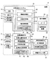
- FIG. 1 is a block diagram showing an overview of a configuration related to automatic driving mounted on a vehicle
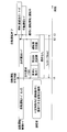
- FIG. 2 is a time chart showing the process of handover in time series
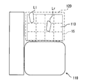
- FIG. 3 is a diagram showing the details of the arrangement of the leg sensor and the position detection of the leg as viewed from the right side of the vehicle
- FIG. 4 is a diagram showing the details of the arrangement of the leg sensor and the position detection of the leg as viewed from the ceiling side of the vehicle
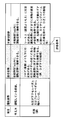
- FIG. 5 is a view showing a list of features of “driving posture”, “appropriate posture” and “inappropriate posture” determined by the state determination unit, FIG.
- FIG. 6 is a diagram showing the concept of actuation in an automatic operation mode implemented by the coordination of the HCU and the presentation device
- FIG. 7 is a flowchart showing the details of the state detection process performed in the automatic operation mode
- FIG. 8 is a diagram showing the details of the arrangement of the leg sensor and the position detection of the leg according to the second embodiment
- FIG. 9 is a diagram showing the details of the arrangement of the leg sensor of the second embodiment and the position detection of the leg
- FIG. 10 is a block diagram showing the configuration of the state detection system of the third embodiment
- FIG. 11 is a diagram showing the details of the arrangement of the leg sensor and the position detection of the leg according to the third embodiment
- FIG. 12 is a diagram showing the details of the arrangement of the leg sensor and the position detection of the leg according to the third embodiment
- FIG. 13 is a diagram showing the details of the arrangement of the leg sensor and the position detection of the leg according to the fourth embodiment
- FIG. 14 is a diagram showing the details of the arrangement of the leg sensor of the fifth embodiment and the position detection of the leg
- FIG. 15 is a diagram showing the details of the arrangement of the leg sensor and the position detection of the leg according to the fifth embodiment
- FIG. 16 is a view showing a list of contents sorted based on the state of the hip joint and the knee joint of the right leg with regard to the division of the “appropriate posture” and the “inappropriate posture”.
- HCU Human Machine Interface
- HCU 30 Human Machine Interface control unit
- the HCU 30 is mounted on the vehicle A together with electronic control units such as a vehicle control ECU (Electronic Control Unit) 80 and an automatic driving ECU 50.
- the HCU 30, the vehicle control ECU 80, and the autonomous driving ECU 50 are directly or indirectly electrically connected to each other, and can communicate with each other.
- the vehicle A has an automatic driving function by the operation of the vehicle control ECU 80 and the automatic driving ECU 50.
- the vehicle control ECU 80 is electrically connected directly or indirectly to the on-vehicle actuator group 91 mounted on the vehicle A.
- the vehicle control ECU 80 integrally controls the operation of the in-vehicle actuator group 91 to control the behavior of the vehicle A.
- the on-vehicle actuator group 91 includes, for example, a throttle actuator of an electronically controlled throttle, an injector, a brake actuator, and a motor generator for driving and regeneration.
- the vehicle control ECU 80 mainly includes a computer having a processing unit, a RAM, a memory device, an input / output interface, and the like.
- the vehicle control ECU 80 constructs an actuator control unit 81 as a functional block related to vehicle control by causing the processing unit to execute a vehicle control program stored in the memory device.
- the actuator control unit 81 generates a control signal output toward the on-vehicle actuator group 91 based on at least one of the operation information based on the driver's driving operation and the autonomous traveling information acquired from the automatic driving ECU 50.
- the autonomous driving ECU 50 is electrically connected directly or indirectly to the GNSS receiver 71, the map database 72, the autonomous sensor group 73, and the like as a configuration for acquiring information necessary for autonomous traveling.
- a GNSS (Global Navigation Satellite System) receiver 71 can receive positioning signals transmitted from a plurality of satellites. The GNSS receiver 71 sequentially outputs the received positioning signal toward the autonomous driving ECU 50 as information for specifying the current position of the vehicle A.
- the GNSS receiver 71 can receive positioning signals transmitted from a plurality of satellites. The GNSS receiver 71 sequentially outputs the received positioning signal toward the autonomous driving ECU 50 as information for specifying the current position of the vehicle A.
- the map database 72 is a storage device storing a large number of map data.
- the map data includes structural information such as curvature, slope, and section length of each road, and non-temporary traffic control information such as speed limit and one-way traffic.
- the map database 72 provides map data of the vicinity of the current position of the vehicle A and the traveling direction to the autonomous driving ECU 50 based on the request from the autonomous driving ECU 50.
- the autonomous sensor group 73 detects moving objects such as pedestrians and other vehicles, and stationary objects such as falling objects on the road, traffic signals, guard rails, curbs, road signs, road markings, and division lines.
- the autonomous sensor group 73 includes, for example, a camera unit, a rider, a millimeter wave radar, and the like.
- the autonomous sensor group 73 sequentially outputs, to the autonomous driving ECU 50, object information on the detected moving object and stationary object respectively.
- the autonomous driving ECU 50 mainly includes a computer having a processing unit 61, a RAM 62, a memory device 63, and an input / output interface.
- the processing unit 61 includes at least one of a central processing unit (CPU), a graphics processing unit (GPU), and a field-programmable gate array (FPGA).
- the processing unit 61 may be provided with a dedicated processor specialized for learning and inference of artificial intelligence (AI).
- AI artificial intelligence
- the autonomous driving ECU 50 performs the acceleration / deceleration control and the steering control of the vehicle A in cooperation with the vehicle control ECU 80, thereby exhibiting an autonomous driving function capable of performing the driving operation of the vehicle A on behalf of the driver.
- the autonomous driving ECU 50 switches a plurality of control modes in which the location of control of the driving operation is different.
- the plurality of control modes include an automatic driving mode in which the vehicle A is autonomously traveled by the automatic driving function, and a manual driving mode in which the vehicle A travels by driving operation of the driver (see FIG. 2).
- the control mode includes a change request mode that is executed at the time of transition from the automatic driving mode to the manual driving mode, and a minimum risk maneuver (MRM) mode for automatically evacuating the vehicle A.
- MRM minimum risk maneuver
- the autonomous driving ECU 50 can execute the autonomous driving program stored in the memory device 63 by the processing unit 61.
- the autonomous driving program includes a program for causing the vehicle A to travel autonomously, a program for controlling driving shift, and the like.
- a self-vehicle position specifying unit 51, an environment recognition unit 52, a plan generation unit 53, an autonomous traveling control unit 54, and the like are constructed in the automatic driving ECU 50.
- the vehicle position specifying unit 51 specifies the current position of the vehicle A based on the positioning signal received by the GNSS receiver 71.
- the vehicle position specifying unit 51 can identify the detailed current position of the vehicle A by collating the image of the front area acquired from the camera unit of the autonomous sensor group 73 with the detailed map data acquired from the map database 72 is there.
- the environment recognition unit 52 combines the position information identified by the vehicle position identification unit 51, the map data acquired from the map database 72, the object information acquired from the autonomous sensor group 73, etc. Recognize the driving environment.
- the environment recognition unit 52 recognizes the shape and movement state of an object around the vehicle A based on the integration result of each object information, particularly within the detection range of each autonomous sensor.
- the environment recognition unit 52 generates a virtual space in which the actual traveling environment is reproduced in three dimensions by combining the information of the recognized surrounding objects with the position information and the map data.
- the plan generation unit 53 Based on the traveling environment recognized by the environment recognition unit 52, the plan generation unit 53 generates a traveling plan for causing the vehicle A to autonomously travel by the automatic driving function.
- a travel plan a long medium-term travel plan and a short-term travel plan are generated.
- a route for directing the vehicle A to a destination set by the driver is defined.
- a planned travel path for realizing travel according to the long-mid-term travel plan is defined. Specifically, executions such as lane tracking and steering for lane change, acceleration / deceleration for speed adjustment, and sudden braking for collision avoidance are determined based on a short-term travel plan.
- the system side acquires the control right at its own discretion in the handover where the control side is deliberately handed over the control to the driver, and in a highly urgent situation There is an override that exists.
- the plan generation unit 53 predicts the occurrence of a situation in which the autonomous traveling can not be continued in the automatic driving mode based on map data in the traveling direction, information acquired from the autonomous sensor group 73, and the like.
- the plan generation unit 53 formulates a handover schedule (hereinafter, “transfer of authority plan”) when it is difficult to formulate a travel plan and it is impossible to continue the automatic driving.
- the off timing of the automatic operation (time t3 in FIG. 2) is defined.
- the execution timing (FIG. 2, time t1 in FIG. 2) of a shift request (hereinafter referred to as “TOR: Take Over Request”) is set, which is reversely calculated from the off timing and requests the driving shift from the automatic driving function to the driver.
- the execution timing of TOR is set to a time earlier by a predetermined allowance time Ta (for example, 4 seconds, see FIG. 2) with respect to the off timing of the automatic operation, and notified to the HCU 30.
- the plan generation unit 53 controls the handover process in the shift request mode in cooperation with the HCU 30 based on the formulated authority transfer plan.
- the autonomous traveling control unit 54 generates autonomous traveling information that instructs acceleration / deceleration and steering of contents based on the planned traveling route formulated by the plan generation unit 53 in the automatic driving mode.
- the autonomous traveling control unit 54 sequentially outputs the generated autonomous traveling information to the vehicle control ECU 80.
- the autonomous traveling control unit 54 cooperates with the actuator control unit 81 to cause the vehicle A to autonomously travel along the planned traveling route.
- the HCU 30 is an electronic control unit provided with a function to control information presentation to the driver in an integrated manner and a function to detect the driver's state.
- the HCU 30 is electrically connected directly or indirectly to the presentation device 20, the DSM (Driver Status Monitor) 11, the leg sensor 12, and the like.
- the presentation device 20 presents various information related to the vehicle A to the occupants of the vehicle A including the driver based on the presentation control signal output by the HCU 30.
- the presentation device 20 includes, for example, a display device that presents information by display, a speaker 21 that presents information by a notification sound and a message voice, and a tactile stimulation device 22 that presents information by vibration.
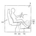
- the tactile stimulation device 22 is provided, for example, on the seat surface 111 (see FIG. 3) or the backrest of the driver's seat 110.
- the DSM 11 is configured of a near infrared light source and a near infrared camera, a control unit that controls these, and the like.
- the DSM 11 is disposed, for example, on the top surface of the steering column in a posture in which the near infrared camera is directed to the driver's seat side.
- the DSM 11 captures the head of the driver who has been irradiated with near-infrared light by the near-infrared light source with a near-infrared camera, and monitors the driver's condition by analyzing the captured face image.
- the DSM 11 sequentially outputs the detection information of the driver obtained by the analysis of the face image to the HCU 30.
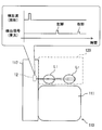
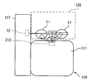
- the leg sensor 12 shown in FIGS. 1, 3 and 4 is, for example, an optical sensor, and is an active type object detection sensor that detects an object by light irradiation.
- the leg sensor 12 is installed on the driver's side of the center console 117.
- the leg sensor 12 is installed at a height position lower than the seating surface 111 and closer to the seating surface 111 of the driver's seat 110 than the floor surface 113 in the vehicle A.
- the leg sensor 12 can individually detect both legs of the driver in the detection space 120.
- the detection space 120 is predefined below the steering wheel 115 and in front of the driver's seat 110.
- the shape and the material of the structure such as the door that divides the detection space 120 in the vehicle compartment are different for each vehicle type. Therefore, it is preferable to define the detection space 120 for each vehicle type in consideration of the shape and the material of the surrounding structure.
- the leg sensor 12 has a light emitting unit 13 and a light receiving unit 14.
- the light projection unit 13 is a light source that emits near infrared light.
- the light projecting unit 13 transmits pulsed near infrared rays as detection waves toward the detection space 120 based on the control of the HCU 30.
- the near infrared rays are spot-irradiated from the light emitting unit 13 along the lateral direction of the vehicle A, for example.
- the light projecting unit 13 repeats irradiation of near infrared rays at predetermined time intervals.
- the directivity (irradiation angle) of the near infrared light is set so as to exceed the thickness of the leg and to have a width such that each pedal or the like is not erroneously detected.
- the light receiving unit 14 is a light receiving element that converts an optical signal into an electrical signal.
- the light receiving unit 14 detects near infrared light reflected by an object located in the detection space 120.
- the near infrared light reflected by the left leg Ll near the center console 117 and the near infrared light reflected by the right leg Lr far from the center console 117 The light receiving unit 14 receives light in order.
- the light receiving unit 14 converts the received light into an electrical signal, and sequentially transmits the signal to the HCU 30 as a detection signal in which the position of the leg is detected.
- the HCU 30 mainly includes a computer having a processing unit 41, a RAM 42, a memory device 43, and an input / output interface.
- the processing unit 41 is configured to include at least one of a central processing unit (CPU), a graphics processing unit (GPU), and a field-programmable gate array (FPGA).
- the processing unit 41 may be provided with a dedicated processor specialized for learning and inference of artificial intelligence (AI).
- the HCU 30 constitutes a state detection system 10 together with the DSM 11 and the leg sensor 12 and the like.
- the state detection system 10 controls the information presentation by the presentation device 20 in the automatic driving mode, and maintains the driver's posture in an appropriate state.
- the HCU 30 causes the processing unit 41 to execute the state detection program stored in the memory device 43, and constructs a plurality of functional blocks related to the state detection and attitude maintenance of the driver. Specifically, in the HCU 30, an information acquisition unit 31, a state determination unit 32, a notification control unit 33, and the like are constructed.
- the information acquisition unit 31 acquires detection information of the driver detected in the DSM 11.
- the information acquisition unit 31 controls the operation of the leg sensor 12 and acquires detection information obtained by detecting the positions of the left and right legs of the driver. Specifically, based on the detection signal of the leg sensor 12, the information acquisition unit 31 measures the difference from the time when the near infrared light is irradiated to the time when the reflected near infrared light is received. Then, the information acquisition unit 31 calculates the positions of the left and right legs from the difference in time, and acquires it as detection information indicating the positions of both legs of the driver.
- the information acquisition unit 31 acquires status information indicating the control mode and the like of the automatic driving ECU 50. For example, when the plan transfer unit 53 formulates an authority transfer plan based on the prediction of occurrence of the system limit of the automatic operation, the information acquisition unit 31 acquires a command instructing execution of TOR from the HCU 30.
- the state determination unit 32 determines whether the driver can cope with the driving change within the allowance time Ta (see FIG. 2) based on the TOR based on the state of the driver's upper body and legs indicated by the detection information. . If there is no problem with the posture of the upper body, the state determination unit 32 classifies the driver's posture into one of "driving posture”, “appropriate posture” and “inappropriate posture” based on the state of the driver's legs. (See FIG. 5).
- the “driving posture” is the posture of the driver in the state of manual driving. If a portion of the right leg Lr beyond the ankle (hereinafter, “right toe”) touches the accelerator pedal or the brake pedal, the state determination unit 32 determines that the “driving posture” is set. .
- the "appropriate attitude” is an attitude that can be returned to the driving attitude within the allowance time Ta (see FIG. 2).
- the “inappropriate attitude” is an attitude that can not return to the driving attitude within the allowance time Ta.
- the state determination unit 32 determines that the driver can not cope with the driving change within the allowance time Ta, and is classified as "inappropriate posture". In this case, it is determined that the driver can not cope with the driving change within the allowance time Ta.
- the state determination unit 32 determines the “appropriate posture” and the “inappropriate posture” mainly based on the estimated position of the driver's right foot tip.
- the state determination unit 32 determines that the driver is in the “appropriate posture”. Even if the portion of the driver's left leg Ll beyond the ankle (hereinafter referred to as the "left toe") is not detected from below the seat surface 111, the condition is still present if the right foot is below the seat surface 111.
- the determination unit 32 determines that the “appropriate posture” capable of coping with the driving change.
- the state determination unit 32 determines that the “inappropriate posture” is set.
- the notification control unit 33 generates a presentation control signal to be output to the presentation device 20 based on the information acquired by the information acquisition unit 31.
- the notification control unit 33 controls the information presentation by display, sound, vibration, and the like by the output of the presentation control signal directed to the presentation device 20.
- the notification control unit 33 instructs the driver to take over the driving operation at time t1 (see FIG. 2) set in the authority transfer plan.
- the requested information presentation is performed using the presentation device 20.
- the driver who has noticed the notification of TOR starts driving operation while correcting the posture after confirming the surrounding situation.
- the state determination unit 32 determines that the state determination unit 32 is in the “driving posture” based on the detection information of the DSM 11 and the leg sensor 12.
- the automatic driving ECU 50 that has acquired the determination result of the state determining unit 32 determines that the driving operation is possible at time t2 (see FIG. 2), and switches the control mode from the shift request mode to the manual driving mode.
- the automatic driving ECU 50 changes the control mode at time t3 (see FIG. 2) Switch from request mode to MRM mode. As a result, the vehicle A stops at the searched evacuation area by evacuation traveling.
- the notification control unit 33 In order to prevent the transition to the MRM mode, the notification control unit 33 returns the driver's state to the “appropriate attitude” when the state determination unit 32 determines that the “improper attitude” is in the automatic driving mode. Is continuously performed using the presentation device 20 (see FIG. 6).
- the notification control unit 33 guides the user to the “appropriate posture” state by information presentation using the speaker 21 and the tactile sense stimulation device 22 when, for example, the driver is performing a sitting position or a sitting position.
- the notification control unit 33 displays “inappropriate posture by information presentation using the speaker 21 and the tactile stimulation device 22. To warn that it is ",” prompting a return to "appropriate attitude". In this way, the driver's condition prior to TOR is maintained so that a drive change may occur.
- the state detection process shown in FIG. 7 is started by the HCU 30 based on switching from the manual operation mode to the automatic operation mode.
- S101 the detection information by the DSM 11 and the leg sensor 12 is acquired, and the process proceeds to S102.
- S102 it is determined whether or not the driver's state is "appropriate attitude" based on the detection information acquired in the immediately preceding S101. If it is determined at S101 that the driver's state is "appropriate posture", the process proceeds to S106. On the other hand, when it is determined in S102 that the driver's state is the "inappropriate posture", the process proceeds to S103.
- S103 based on the state of the driver detected in S102, the guidance or warning for prompting the return to the "appropriate posture” is performed, and the process proceeds to S104 and S105.
- S104 and S105 as in S101 and S102, it is determined based on the detection information whether the driver has returned to the "appropriate posture". If it is determined in S105 that the "appropriate posture” is restored, the process returns to S101 and the state detection process is continued. On the other hand, when the driver's posture does not return to the “appropriate posture”, the information presentation to prompt the correction of the sitting posture is continued by repeating the processing of S103 to S105.
- S106 when it is determined in S102 that the “appropriate posture” is set, it is determined whether a notification instruction of TOR based on the limit prediction of the system is acquired from the autonomous driving ECU 50 or not. If it is determined in S106 that the start of TOR has been instructed, the process proceeds to a process for implementing TOR. On the other hand, when it is determined that the automatic driving mode is to be continued, the process returns to S101, and the state detection process is continued.
- the HCU 30 notifies TOR. In this case, after the notification of TOR, the HCU 30 provides the automatic driving ECU 50 with a determination result indicating that return to the “driving posture” is not possible. Based on the determination result, the autonomous driving ECU 50 starts transitioning to the MRM mode before the elapse of the margin time Ta (see FIG. 2).
- the position of the driver's leg is acquired as detection information. And it is judged based on the state of a driver's leg whether a driver can cope with the driving change based on TOR. According to the above, it is possible to determine that the TOR can not be handled when the leg posture is inappropriate for driving operation.
- the state determination unit 32 determines that the “appropriate posture” is set. If at least the right toe is below the seating surface 111, the driver can start the operation of the accelerator pedal or the brake pedal within the allowance time Ta after the occurrence of TOR. Therefore, if it is determined that it is possible to cope with TOR based on the position of the right toe, execution of driving alternation for a driver who can not cope with TOR can be avoided while reducing the calculation load of attitude determination.
- the leg sensor 12 of the first embodiment detects the driver's leg in a detection space 120 defined below the steering wheel 115 and in front of the driver's seat 110.
- the state determination unit 32 can determine whether the state of the driver's leg can handle TOR. Therefore, complication of the configuration of the leg sensor 12 can be avoided while securing the accuracy of the state determination of the driver.
- the detection space 120 described above is a very dark space because ambient light is blocked by an instrument panel, a steering column, and the like. Therefore, if the active type optical sensor that emits near infrared light is used as the leg sensor 12, the information acquisition unit 31 can acquire the detection information without being affected by the brightness around the vehicle A.
- the state detection system 10 of the first embodiment no camera is used to detect the state of the leg. Therefore, by matching the pattern of the posture taken by the driver with the image data captured at that time, the number of development steps for creating a determiner for determining the driver's posture becomes unnecessary. Furthermore, by not using a camera for detecting the state of the leg, a highly marketable state detection system 10 can be realized in consideration of the driver's privacy problem.
- the leg sensor 12 of the first embodiment is installed at a height position closer to the seating surface 111 than the floor surface 113.
- the positions of the legs are positions farther from the knees, and the portions closer to the floor surface 113 are more likely to be scattered along the floor surface 113 in the front, rear, left, and right.
- the height of the seating surface 111 is close, the position of the leg (knee) does not change significantly. Therefore, if the leg sensor 12 is disposed at a height close to the seat surface 111, even if the irradiation range (directivity) of the near infrared light (detection wave) is narrowed, detection leakage hardly occurs. Therefore, the leg sensor 12 can be simplified while securing the detection accuracy of the position of the leg.
- the leg sensor 12 corresponds to a "position detection sensor”
- the light emitting unit 13 corresponds to a “transmission unit”
- the light receiving unit 14 corresponds to a “detection unit”
- the HCU 30 is in a "state”.
- the leg sensor 12 corresponds to a "position detection sensor”
- the light emitting unit 13 corresponds to a "transmission unit”
- the light receiving unit 14 corresponds to a “detection unit”
- the HCU 30 is in a "state”.
- the HCU 30 is in a "state”.
- the second embodiment shown in FIGS. 8 and 9 is a modification of the first embodiment.
- the leg sensor 212 of the second embodiment is an optical sensor as in the first embodiment, and is installed at a position different from that of the first embodiment.
- the leg sensor 212 is housed in front of the seat portion of the driver's seat 110 and at a height position closer to the seat 111 than the floor surface 113.
- the light emitting unit 213 of the leg sensor 212 emits near infrared light toward the detection space 120 defined in the front.
- the light projection unit 213 can scan the light irradiation direction at least in the horizontal direction.
- the light projection unit 213 repeats the irradiation of the near-infrared light at predetermined time intervals while turning the light irradiation direction in the horizontal direction.
- the directivity (irradiation angle) of the near infrared light is narrowed to about the thickness of the leg. For example, when the near infrared light is emitted in the left direction, the near infrared light reflected by the left leg L1 is detected by the light receiving unit 214. Similarly, when the near infrared light is emitted in the right direction, the near infrared light reflected by the right leg Lr is detected by the light receiving unit 214.
- the information acquisition unit 31 (see FIG. 1) individually detects the positions of the driver's legs in the detection space 120 based on the detection signal received from the leg sensor 212. Specifically, the information acquisition unit 31 estimates the positions of both legs based on the irradiation direction of the near infrared light by the light projection unit 213 and the difference time from the irradiation time to the light reception time.
- the reflected light detected after progress of predetermined time ts from the irradiation time of near infrared rays is filtered as light reflected by the structure of the vehicle A out of the area
- the information acquisition unit 31 detects the presence and the position of each of the legs Ll and Lr based on the reflected light received until the predetermined time ts elapses from the irradiation time.
- the structure of the vehicle A represented by the door is defined in shape and material for each vehicle type. Therefore, the light reception time and the light reception intensity of the reflected light are previously known values. From such a thing, light reception time and light reception intensity according to a structure around detection space 120 may be set up beforehand, and distinction with a leg and a structure may be carried out.
- the same effect as that of the first embodiment can be obtained, and it can be determined that TOR can not be handled when the posture of the leg unsuitable for driving operation is taken.
- the information acquisition unit 31 determines whether the two legs are aligned in the front-rear direction of the vehicle A, based on the detection signal, You can know the position of both legs.
- the leg sensor 212 corresponds to a “position detection sensor”
- the light emitting unit 213 corresponds to a “transmission unit”
- the light receiving unit 214 corresponds to a “detection unit”.
- the third embodiment shown in FIGS. 10 to 12 is another modification of the first embodiment.
- the state detection system 310 of the third embodiment includes the HCU 30 and the DSM 11 substantially the same as the first embodiment.
- the state detection system 310 has the leg sensor 12 substantially the same as the first embodiment and the leg sensor 212 substantially the same as the second embodiment as a configuration for detecting the driver's legs.
- the state detection system 310 detects the driver's legs in the detection space 120 from different directions using the two leg sensors 12 and 212.
- the two leg sensors 12 and 212 are both provided at a height closer to the seating surface 111 than the floor surface 113.
- the leg sensor 12 disposed on the center console 117 is installed at a position slightly higher than the leg sensor 212 disposed on the driver's seat 110 in the height direction of the vehicle A (see FIG. 11).
- the information acquisition unit 31 integrates detection signals output from the two leg sensors 12 and 212, and estimates the positions of the legs Ll and Lr in the detection space 120.
- the same effects as in the first embodiment can be obtained, and it can be determined that TOR can not be handled when the posture of the leg unsuitable for driving operation is taken.
- the HCU 30 can more accurately acquire the state of the driver's two legs and appropriately determine whether or not the driving alternation is possible. It can be carried out.
- both of the leg sensors 12 and 212 correspond to the "position detection sensor".
- the fourth embodiment shown in FIG. 13 is still another modification of the first embodiment.
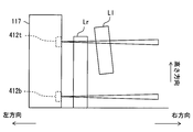
- two leg sensors 412t and 412b are provided on the center console 117.
- Each of the leg sensors 412t and 412b has substantially the same configuration as the leg sensor 12 (see FIG. 1) of the first embodiment.
- the leg sensor 412t is provided at a position higher than the leg sensor 412b in the height direction of the vehicle.
- the leg sensor 412t is disposed rearward of the leg sensor 412b in the front-rear direction of the vehicle.
- the information acquisition unit 31 can detect, for example, a state where the legs are assembled on the knee, from detection signals of the two leg sensors 412t and 412b. Specifically, in the state of being assembled on the knee, the upper leg sensor 412t outputs a detection signal in which both the right leg Lr and the left leg Ll are detected. On the other hand, the lower leg sensor 412b outputs a detection signal in which only the right leg Lr is detected. The information acquisition unit 31 can estimate the state of the driver's leg set from the combination of these two detection signals.
- the same effect as that of the first embodiment can be obtained, and it can be determined that it can not cope with TOR when the posture of the leg unsuitable for driving operation is taken.
- the HCU 30 by using the detection information of the upper and lower two leg sensors 412t and 412b, the HCU 30 appropriately grasps the state of the leg that is difficult to return to the driving posture, and to the driver who can not cope with TOR. It is possible to avoid the implementation of driving changes.
- both of the leg sensors 412t and 412b correspond to the "position detection sensor".
- the fifth embodiment shown in FIGS. 14 and 15 is still another modification of the first embodiment.
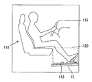
- a floor sensor 15 is provided instead of the leg sensor 12 (see FIG. 1) of the first embodiment.
- the floor sensor 15 is a sensor that detects both legs Ll and Lr of the driver from the detection space 120 below the steering wheel 115 and in front of the driver's seat 110, similarly to the leg sensor 12.
- the floor sensor 15 is formed in a sheet shape and is provided on the back side of the floor surface 113.
- the floor sensor 15 is formed to have the same size as the bottom surface of the detection space 120 so as to indirectly reach the entire bottom surface of the detection space 120.
- the floor sensor 15 has a plurality of pressure detection units arranged in a two-dimensional manner.
- the pressure detection unit is provided, for example, one by one in each of the areas (see the dashed-dotted line in FIG. 15) in which the floor sensor 15 is partitioned in a grid shape.
- Each pressure detection unit detects a load due to the foot sole being placed on the floor surface 113.
- the floor sensor 15 sequentially outputs the pressure acting on each area as a detection signal to the HCU 30 (see FIG. 1).
- the information acquisition unit 31 detects the pressure (load) acting on each area of the floor sensor 15. Based on such detection information, the state determination unit 32 (see FIG. 1) detects the footprints of both legs Ll and Lr from the detection space 120, for example, a pressure equal to or greater than a threshold acts on at least two regions. Is determined to be an "appropriate attitude". On the other hand, if only one area is affected by pressure above the threshold, etc., and only one foot footprint can be detected, and if pressure above the threshold is not applied to any area and even one foot footprint can not be detected, The state determination unit 32 determines that the “inappropriate posture” is set.
- the sixth embodiment of the present disclosure is a modification of the first embodiment shown in FIGS. 1 and 2.
- the allowance time Ta set in the authority transfer plan is variable. For example, when the traveling environment of the vehicle A is good (such as fine weather) and the detection distance of the autonomous sensor group 73 is sufficiently long, the autonomous driving ECU 50 grasps the distant situation and hasten the off timing of the autonomous driving. You can perform TOR at the timing. Specifically, it becomes possible to formulate an authority transfer plan that secures an allowance time Ta of about 10 seconds.
- the allowance time Ta set in the authority transfer plan is shorter than that in the case of a good traveling environment, for example, about 4 seconds.
- the state determination unit 32 sets allowance criteria (see FIG. 5) for dividing “appropriate attitude” and “inappropriate attitude” into the allowance time Ta. Vary according to the length of That is, if the margin time Ta becomes long, the tolerance standard is relaxed. On the contrary, if the margin time Ta becomes short, the tolerance standard becomes stricter.
- the driver's posture such as a seat on the seat or a seat on the seat, and a leg set on the knee is determined as "appropriate posture" in a traveling environment where a sufficient allowance time Ta can be secured (approximately 10 seconds). In the traveling environment where the allowance time Ta is short (about 4 seconds), it is determined as "inappropriate posture”.
- the posture in which the right foot tip is hooked on the steering wheel 115 (see FIG. 3), the door on the driver's seat side, etc. is determined to be “inappropriate posture” regardless of the allowance time Ta.
- the state determination unit 32 makes the tolerance standard stricter as the remaining time until the off timing of the automatic operation becomes shorter after the TOR. For example, at the timing when the remaining time until the off timing of the automatic driving is about 4 seconds, the state determination unit 32 sets “appropriate postures such as a sitting position on the seat and a leg on the knee. It is determined that the "inappropriate posture" is not "posture”.
- the same effect as that of the first embodiment can be obtained, and when the posture of the leg unsuitable for driving operation is taken, it is possible to obtain the determination result that it can not cope with TOR. .
- the allowance criteria for separating the "appropriate posture" and the "inappropriate posture” may be changed in accordance with the length of the margin time Ta that can be secured in the shift request mode. According to such control, since the driver's permitted posture is increased in the automatic driving mode, unnecessary guidance for posture correction is reduced. According to the above, it is possible to provide an automatic driving function that is useful for a user such as a driver.
- the margin time set in the authority transfer plan is longer than the first embodiment and the like and is set to a fixed length (for example, 10 seconds). Therefore, in the first modification, the change of the acceptance criteria in the automatic operation mode is not performed. For example, if the detection distance and accuracy of the autonomous sensor group are sufficient, such setting is possible. Therefore, in the automatic driving mode, postures such as a black seat, a straight seat, and a leg set on the knee are allowed.
- the state determination unit makes the tolerance standard stricter as the remaining time until the automatic driving off timing becomes shorter after TOR. Specifically, at the timing when the remaining time until the off timing of the automatic driving becomes less than a predetermined threshold (for example, 4 seconds), the state determination unit determines the posture such as the leg set on the palm, the straight seat, and the knee. , Not the "appropriate attitude” but the "inappropriate attitude”. As a result, the driver who takes the above attitude is warned at an appropriate timing.
- a predetermined threshold for example, 4 seconds
- the state determination unit may change the tolerance reference at an appropriate timing such as after TOR.
- the specific value of the spare time may be changed as appropriate according to the laws and guidelines of the area where the vehicle is used, the speed limit of the road on which the vehicle travels, and the like.
- an optical sensor, a floor sensor, and the like are employed as the configuration for detecting the position of the leg.
- a line sensor, an ultrasonic sensor or the like can be employed.
- a vibrating unit that oscillates an ultrasonic wave as a detection wave corresponds to a "transmission unit”
- a receiving unit that receives an ultrasonic wave reflected by a leg corresponds to a "detection unit”.
- various active and passive object detection sensors can be employed as sensors for detecting the position of the leg.
- the above-described method of distinguishing between a leg and a structure is also applicable to a form using an ultrasonic sensor or the like.
- the sensor provided in the state detection system can detect the attitude of the dot range shown in FIG.
- the posture of the driver's right leg directly linked to the pedal operation is defined by the hip joint angle ⁇ h and the knee joint angle ⁇ b, and the driver's posture when the joint angles ⁇ h and ⁇ b are changed. Is shown in the list.
- the range of the dot is a range of posture in which the change of the body axis is unnecessary until it is returned to the correct driving posture.
- the leg set under the knee is classified into the “appropriate posture” because it is not necessary to change the body axis to return to the driving posture.
- the right leg by stretching the right leg, if it is hung on the right door or window or the steering wheel 115, it is necessary to change the body axis to return to the driving posture.
- the leg is set on the knee, it is necessary to change the body axis. Therefore, these postures are divided into "inappropriate postures”.
- the “appropriate posture” and the “inappropriate posture” are determined from the state of the right leg based on the detection of the leg sensor.
- the detection information of the in-vehicle camera provided in front of and above the driver is combined with the detection information of the leg sensor, for example, the posture as described above in which the right leg is thrown forward can be specified. Therefore, with the state detection system that detects the driver's state by combining the detection results of the upper body and the leg, it is possible to implement a highly accurate alerting.
- the range of the detection space by the position detection sensor may be changed as appropriate.
- the condition of the driver's hip located on the seat may be detected.
- the position of the position detection sensor can also be changed in accordance with the setting range of the detection space.
- the position detection sensor may be installed on the side surface of the center cluster, the lower surface of the steering column, and in the vicinity of the pedal.
- the configuration for monitoring the driver's upper body is not limited to the DSM.
- the state detection system may include, for example, an electrostatic sensor or a pressure sensor that detects the grip of the steering wheel 115 (see FIG. 3), or the above-described in-vehicle camera or the like, together with or in place of the DSM.
- configurations such as DSM may be omitted from the state detection system.
- the automatic driving ECU enables so-called automatic driving of eye-off, which takes charge of monitoring of the traveling environment on behalf of the driver.
- the driver's state detection method is suitable for the driver's attitude detection in a period in which the level 3 automatic driving is performed.
- the state detection method according to the present disclosure is also applicable to level 2 automatic driving in which monitoring of the driving environment is performed by the driver.
- a state detection apparatus may be implement
- the processing unit of the electronic control unit in which the autonomous driving ECU and the HCU are integrally configured may implement the state detection method described above.
- a plurality of electronic control devices including the HCU, the autonomous driving ECU, and the vehicle control ECU may process the state detection program according to the present disclosure in a distributed manner.
- non-transitory tangible storage media such as flash memories and hard disks can be employed in a memory device such as an HCU as a configuration for storing a state detection program.
- the storage medium for storing the state detection program is not limited to the storage medium provided in the on-vehicle electronic control unit, and may be an optical disc as a copy source to the storage medium, a hard disk drive of a general purpose computer May be
- each unit is expressed as S101, for example.
- each part can be divided into a plurality of sub-parts, while a plurality of parts can be combined into one part.
- each part configured in this way can be referred to as a circuit, a device, a module, or a means.
- hardware unit e.g., computer
- hardware e.g., an integrated circuit, As part of hardwired logic, it may be implemented with or without the functionality of the associated device.
- the hardware part can also be configured inside the microcomputer.
Abstract
In a vehicle provided with an automatic driving function that is capable of performing a driving operation in place of a driver, this state detection device for detecting the driver's state is provided with: an information acquisition unit (31) that acquires detection information obtained by detecting the driver's leg position; and a state determination unit (32) that determines whether the driver can accept a driving change based on a change request from the automatic driving function on the basis of the driver's leg state indicated by the detection information. This state detection system includes: the state detection device; and position detection sensors (12, 212, 412t, and 412b) that output, to the information acquisition unit, detection signals obtained by detecting the leg position.
Description
本出願は、2017年10月4日に出願された日本特許出願番号2017-194618号に基づくもので、ここにその記載内容を援用する。
This application is based on Japanese Patent Application No. 2017-194618 filed on October 4, 2017, the contents of which are incorporated herein by reference.
この明細書による開示は、自動運転機能を備える車両において運転者の状態を検出する状態検出装置、状態検出システム及び状態検出プログラムに関する。
The disclosure of this specification relates to a state detection device, a state detection system, and a state detection program for detecting a driver's state in a vehicle provided with an autonomous driving function.
従来、例えば特許文献1には、運転者に代わって運転操作を実施可能な車両制御装置が開示されている。車両制御装置は、ハンドオーバーとして、自動運転の状態から運転者による手動運転への運転交代を実施する。さらに車両制御装置は、運転者が手動運転に復帰できる状態か否かを、例えばステアリングコラムの上面に設けられたドライバモニタカメラ、及びステアリングホールに設けられたタッチセンサ等によって検出する。
BACKGROUND ART Conventionally, for example, Patent Document 1 discloses a vehicle control device capable of performing a driving operation on behalf of a driver. The vehicle control device performs a driving change from the state of automatic driving to the manual driving by the driver as the handover. Further, the vehicle control device detects whether or not the driver can return to the manual driving, for example, by a driver monitor camera provided on the top surface of the steering column, a touch sensor provided on the steering hole, or the like.
さて、運転操作に不適切な脚の姿勢が取られている場合にも、運転者は、ハンドオーバーによる運転交代に対応困難となる。しかし、特許文献1の車両制御装置では、運転交代に運転者が対応可能か否かは、主に運転者の上半身の状態に基づいて判定される。故に、脚の姿勢が運転操作に不適切であっても、車両制御装置は、運転者が交代要求に対応できないと判定することが難しかった。
Now, even when the posture of the leg is inappropriate for the driver's operation, the driver has difficulty in dealing with the driving change due to the handover. However, in the vehicle control device of Patent Document 1, it is mainly determined based on the state of the upper body of the driver whether the driver can cope with the driving change. Therefore, it was difficult for the vehicle control device to determine that the driver can not respond to the shift request even if the posture of the leg is inappropriate for the driving operation.
本開示は、運転操作に不適切な脚の姿勢が取られている場合に、運転者が交代要求に対応できなと判定可能な状態検出装置、状態検出システム及び状態検出プログラムの提供を目的とする。
An object of the present disclosure is to provide a state detection device, a state detection system, and a state detection program that can determine that the driver can not respond to the shift request when the posture of the leg is inappropriate for driving operation. Do.
本開示の一つの態様による状態検出装置は、運転者に代わって運転操作を実施可能な自動運転機能を備える車両において、運転者の状態を検出する状態検出装置であって、運転者の脚の位置を検出した検出情報を取得する情報取得部と、検出情報の示す運転者の脚の状態に基づき、自動運転機能からの交代要求に基づく運転交代に運転者が対応可能か否かを判定する状態判定部と、を備える。
A state detection device according to one aspect of the present disclosure is a state detection device that detects a state of a driver in a vehicle having an automatic driving function capable of performing a driving operation on behalf of the driver, and includes: Based on the information acquisition unit that acquires detection information at which the position is detected, and the driver's leg state indicated by the detection information, it is determined whether the driver can cope with the drive change based on the change request from the automatic drive function. And a state determination unit.
本開示の他の態様による状態検出プログラムは、運転者に代わって運転操作を実施可能な自動運転機能を備える車両において、運転者の状態を検出する状態検出プログラムであって、少なくとも一つの処理部を、運転者の脚の位置を検出した検出情報を取得する情報取得部、検出情報の示す運転者の脚の状態に基づき、自動運転機能からの交代要求に基づく運転交代に運転者が対応可能か否かを判定する状態判定部、として機能させる指令を含む。
A state detection program according to another aspect of the present disclosure is a state detection program for detecting a state of a driver in a vehicle having an automatic driving function capable of performing a driving operation on behalf of the driver, at least one processing unit The driver can respond to driving change based on the request for change from the automatic driving function based on the information acquisition unit that acquires the detection information that detects the position of the driver's leg, and the state of the driver's leg indicated by the detection information And a command to function as a state determination unit that determines whether or not to
本開示の他の態様による状態検出システムは、上記状態検出装置と、脚の位置を検出した検出信号を情報取得部へ向けて出力する位置検出センサと、を含み、位置検出センサは、検出空間へ向けて検出波を発信する発信部、及び検出空間に位置する物体によって反射された検出波を検出する検出部、を有する。
A state detection system according to another aspect of the present disclosure includes the above-described state detection device, and a position detection sensor that outputs a detection signal that detects the position of a leg toward an information acquisition unit, and the position detection sensor It has a transmission part which transmits a detection wave to the direction, and a detection part which detects a detection wave reflected by an object located in a detection space.
上記状態検出装置、状態検出システム及び状態検出プログラムによれば、運転者の脚の位置が検出情報として取得される。そして、交代要求に基づく運転交代に運転者が対応可能か否かは、運転者の脚の状態に基づき判定される。以上によれば、運転操作に不適切な脚の姿勢が取られている場合には、自動運転機能からの交代要求に対応できないと判定することが可能になる。
According to the state detection device, the state detection system, and the state detection program, the position of the driver's leg is acquired as detection information. Then, whether the driver can cope with the driving change based on the change request is determined based on the state of the driver's leg. According to the above, it is possible to determine that it is not possible to respond to the shift request from the automatic driving function when the posture of the leg that is inappropriate for the driving operation is taken.
本開示についての上記目的およびその他の目的、特徴や利点は、添付の図面を参照しながら下記の詳細な記述により、より明確になる。その図面は、
図1は、車両に搭載された自動運転に関連する構成の全体像を示すブロック図であり、
図2は、ハンドオーバーのプロセスを時系列に沿って示すタイムチャートであり、
図3は、車両の右側から見た脚センサの配置と脚の位置検出の詳細を示す図であり、
図4は、車両の天井側から見た脚センサの配置と脚の位置検出の詳細を示す図であり、
図5は、状態判定部にて判定される「運転姿勢」,「適切姿勢」及び「不適切姿勢」の特徴を一覧で示す図であり、
図6は、HCU及び提示装置の連携によって実施される自動運転モードでのアクチュエーションの考え方を示す図であり、
図7は、自動運転モードにて実施される状態検出処理の詳細を示すフローチャートであり、
図8は、第二実施形態の脚センサの配置と脚の位置検出の詳細を示す図であり、
図9は、第二実施形態の脚センサの配置と脚の位置検出の詳細を示す図であり、
図10は、第三実施形態の状態検出システムの構成を示すブロック図であり、
図11は、第三実施形態の脚センサの配置と脚の位置検出の詳細を示す図であり、
図12は、第三実施形態の脚センサの配置と脚の位置検出の詳細を示す図であり、
図13は、第四実施形態の脚センサの配置と脚の位置検出の詳細を示す図であり、
図14は、第五実施形態の脚センサの配置と脚の位置検出の詳細を示す図であり、
図15は、第五実施形態の脚センサの配置と脚の位置検出の詳細を示す図であり、
図16は、「適切姿勢」及び「不適切姿勢」の区分けについて、右脚の股関節及び膝関節の状態に基づき整理した内容を一覧にて示す図である。
The above object and other objects, features and advantages of the present disclosure will become more apparent from the following detailed description with reference to the attached drawings. The drawing is
FIG. 1 is a block diagram showing an overview of a configuration related to automatic driving mounted on a vehicle, FIG. 2 is a time chart showing the process of handover in time series; FIG. 3 is a diagram showing the details of the arrangement of the leg sensor and the position detection of the leg as viewed from the right side of the vehicle; FIG. 4 is a diagram showing the details of the arrangement of the leg sensor and the position detection of the leg as viewed from the ceiling side of the vehicle; FIG. 5 is a view showing a list of features of “driving posture”, “appropriate posture” and “inappropriate posture” determined by the state determination unit, FIG. 6 is a diagram showing the concept of actuation in an automatic operation mode implemented by the coordination of the HCU and the presentation device, FIG. 7 is a flowchart showing the details of the state detection process performed in the automatic operation mode, FIG. 8 is a diagram showing the details of the arrangement of the leg sensor and the position detection of the leg according to the second embodiment, FIG. 9 is a diagram showing the details of the arrangement of the leg sensor of the second embodiment and the position detection of the leg; FIG. 10 is a block diagram showing the configuration of the state detection system of the third embodiment, FIG. 11 is a diagram showing the details of the arrangement of the leg sensor and the position detection of the leg according to the third embodiment; FIG. 12 is a diagram showing the details of the arrangement of the leg sensor and the position detection of the leg according to the third embodiment, FIG. 13 is a diagram showing the details of the arrangement of the leg sensor and the position detection of the leg according to the fourth embodiment, FIG. 14 is a diagram showing the details of the arrangement of the leg sensor of the fifth embodiment and the position detection of the leg; FIG. 15 is a diagram showing the details of the arrangement of the leg sensor and the position detection of the leg according to the fifth embodiment, FIG. 16 is a view showing a list of contents sorted based on the state of the hip joint and the knee joint of the right leg with regard to the division of the “appropriate posture” and the “inappropriate posture”.
以下、本開示の複数の実施形態を図面に基づいて説明する。尚、各実施形態において対応する構成要素には同一の符号を付すことにより、重複する説明を省略する場合がある。各実施形態において構成の一部分のみを説明している場合、当該構成の他の部分については、先行して説明した他の実施形態の構成を適用することができる。また、各実施形態の説明において明示している構成の組み合わせばかりではなく、特に組み合わせに支障が生じなければ、明示していなくても複数の実施形態の構成同士を部分的に組み合わせることができる。そして、複数の実施形態及び変形例に記述された構成同士の明示されていない組み合わせも、以下の説明によって開示されているものとする。
Hereinafter, a plurality of embodiments of the present disclosure will be described based on the drawings. In addition, the overlapping description may be abbreviate | omitted by attaching the same code | symbol to the corresponding component in each embodiment. When only a part of the configuration is described in each embodiment, the configuration of the other embodiments described above can be applied to other parts of the configuration. Further, not only the combination of the configurations explicitly described in the description of the respective embodiments but also the configurations of the plurality of embodiments can be partially combined with each other even if the combination is not specified unless any trouble occurs in the combination. And the combination which has not been specified between the configurations described in a plurality of embodiments and modifications is also disclosed by the following description.
(第一実施形態)
本開示の第一実施形態による状態検出装置の機能は、図1に示すHCU(HMI(Human Machine Interface)Control Unit)30によって実現されている。HCU30は、車両制御ECU(Electronic Control Unit)80及び自動運転ECU50等の電子制御ユニットと共に車両Aに搭載されている。HCU30、車両制御ECU80及び自動運転ECU50は、直接的又は間接的に互い電気接続されており、相互に通信可能である。車両Aは、車両制御ECU80及び自動運転ECU50の作動により、自動運転機能を備える。 First Embodiment
The function of the state detection device according to the first embodiment of the present disclosure is realized by an HCU (Human Machine Interface) control unit (HCU) 30 shown in FIG. The HCU 30 is mounted on the vehicle A together with electronic control units such as a vehicle control ECU (Electronic Control Unit) 80 and anautomatic driving ECU 50. The HCU 30, the vehicle control ECU 80, and the autonomous driving ECU 50 are directly or indirectly electrically connected to each other, and can communicate with each other. The vehicle A has an automatic driving function by the operation of the vehicle control ECU 80 and the automatic driving ECU 50.
本開示の第一実施形態による状態検出装置の機能は、図1に示すHCU(HMI(Human Machine Interface)Control Unit)30によって実現されている。HCU30は、車両制御ECU(Electronic Control Unit)80及び自動運転ECU50等の電子制御ユニットと共に車両Aに搭載されている。HCU30、車両制御ECU80及び自動運転ECU50は、直接的又は間接的に互い電気接続されており、相互に通信可能である。車両Aは、車両制御ECU80及び自動運転ECU50の作動により、自動運転機能を備える。 First Embodiment
The function of the state detection device according to the first embodiment of the present disclosure is realized by an HCU (Human Machine Interface) control unit (HCU) 30 shown in FIG. The HCU 30 is mounted on the vehicle A together with electronic control units such as a vehicle control ECU (Electronic Control Unit) 80 and an
車両制御ECU80は、車両Aに搭載された車載アクチュエータ群91と直接的又は間接的に電気接続されている。車両制御ECU80は、車載アクチュエータ群91の作動を統合的に管理することで、車両Aの挙動を制御する。車載アクチュエータ群91には、例えば電子制御スロットルのスロットルアクチュエータ、インジェクタ、ブレーキアクチュエータ、並びに駆動用及び回生用のモータジェネレータが含まれている。
The vehicle control ECU 80 is electrically connected directly or indirectly to the on-vehicle actuator group 91 mounted on the vehicle A. The vehicle control ECU 80 integrally controls the operation of the in-vehicle actuator group 91 to control the behavior of the vehicle A. The on-vehicle actuator group 91 includes, for example, a throttle actuator of an electronically controlled throttle, an injector, a brake actuator, and a motor generator for driving and regeneration.
車両制御ECU80は、処理部、RAM、メモリ装置、及び入出力インターフェース等を有するコンピュータを主体に構成されている。車両制御ECU80は、メモリ装置に記憶された車両制御プログラムを処理部によって実行することにより、車両制御に係る機能ブロックとしてアクチュエータ制御部81を構築する。アクチュエータ制御部81は、運転者の運転操作に基づく操作情報及び自動運転ECU50から取得される自律走行情報の少なくとも一方に基づき、車載アクチュエータ群91へ向けて出力される制御信号を生成する。
The vehicle control ECU 80 mainly includes a computer having a processing unit, a RAM, a memory device, an input / output interface, and the like. The vehicle control ECU 80 constructs an actuator control unit 81 as a functional block related to vehicle control by causing the processing unit to execute a vehicle control program stored in the memory device. The actuator control unit 81 generates a control signal output toward the on-vehicle actuator group 91 based on at least one of the operation information based on the driver's driving operation and the autonomous traveling information acquired from the automatic driving ECU 50.
自動運転ECU50は、自律走行に必要な情報を取得する構成として、GNSS受信器71、地図データベース72及び自律センサ群73等と直接的又は間接的に電気接続されている。
The autonomous driving ECU 50 is electrically connected directly or indirectly to the GNSS receiver 71, the map database 72, the autonomous sensor group 73, and the like as a configuration for acquiring information necessary for autonomous traveling.
GNSS(Global Navigation Satellite System)受信器71は、複数の人工衛星から送信された測位信号を受信可能である。GNSS受信器71は、受信した測位信号を、車両Aの現在位置を特定するための情報として、自動運転ECU50へ向けて逐次出力する。
A GNSS (Global Navigation Satellite System) receiver 71 can receive positioning signals transmitted from a plurality of satellites. The GNSS receiver 71 sequentially outputs the received positioning signal toward the autonomous driving ECU 50 as information for specifying the current position of the vehicle A.
地図データベース72は、多数の地図データを格納している記憶装置である。地図データには、各道路の曲率、勾配、及び区間の長さといった構造情報、並びに制限速度及び一方通行といった非一時的な交通規制情報等が含まれている。地図データベース72は、自動運転ECU50からの要求に基づき、車両Aの現在位置の周辺及び進行方向の地図データを自動運転ECU50に提供する。
The map database 72 is a storage device storing a large number of map data. The map data includes structural information such as curvature, slope, and section length of each road, and non-temporary traffic control information such as speed limit and one-way traffic. The map database 72 provides map data of the vicinity of the current position of the vehicle A and the traveling direction to the autonomous driving ECU 50 based on the request from the autonomous driving ECU 50.
自律センサ群73は、歩行者及び他の車両等の移動物体、さらに路上の落下物、交通信号、ガードレール、縁石、道路標識、道路標示、及び区画線等の静止物体を検出する。自律センサ群73には、例えばカメラユニット、ライダ及びミリ波レーダ等が含まれている。自律センサ群73はそれぞれ、検出した移動物体及び静止物体に係る物体情報を、自動運転ECU50へ向けて逐次出力する。
The autonomous sensor group 73 detects moving objects such as pedestrians and other vehicles, and stationary objects such as falling objects on the road, traffic signals, guard rails, curbs, road signs, road markings, and division lines. The autonomous sensor group 73 includes, for example, a camera unit, a rider, a millimeter wave radar, and the like. The autonomous sensor group 73 sequentially outputs, to the autonomous driving ECU 50, object information on the detected moving object and stationary object respectively.
自動運転ECU50は、処理部61、RAM62、メモリ装置63及び入出力インターフェースを有するコンピュータを主体に構成されている。処理部61は、CPU(Central Processing Unit)、GPU(Graphics Processing Unit)及びFPGA(Field-Programmable Gate Array)等の少なくとも一つを含む構成である。処理部61には、AI(Artificial Intelligence)の学習及び推論に特化した専用のプロセッサが設けられていてもよい。
The autonomous driving ECU 50 mainly includes a computer having a processing unit 61, a RAM 62, a memory device 63, and an input / output interface. The processing unit 61 includes at least one of a central processing unit (CPU), a graphics processing unit (GPU), and a field-programmable gate array (FPGA). The processing unit 61 may be provided with a dedicated processor specialized for learning and inference of artificial intelligence (AI).
自動運転ECU50は、車両制御ECU80との連携によって車両Aの加減速制御及び操舵制御を行うことにより、運転者に代わって車両Aの運転操作を実施可能な自動運転機能を発揮する。自動運転ECU50は、運転操作の制御権の所在が異なる複数の制御モードを切り替える。複数の制御モードには、自動運転機能によって車両Aを自律走行させる自動運転モード、及び運転者の運転操作によって走行する手動運転モードが含まれている(図2参照)。さらに、自動運転モードから手動運転モードへの遷移時に実行される交代要求モード、及び車両Aを自動退避させるためのMRM(Minimum Risk Maneuver)モードが、制御モードには含まれている。
The autonomous driving ECU 50 performs the acceleration / deceleration control and the steering control of the vehicle A in cooperation with the vehicle control ECU 80, thereby exhibiting an autonomous driving function capable of performing the driving operation of the vehicle A on behalf of the driver. The autonomous driving ECU 50 switches a plurality of control modes in which the location of control of the driving operation is different. The plurality of control modes include an automatic driving mode in which the vehicle A is autonomously traveled by the automatic driving function, and a manual driving mode in which the vehicle A travels by driving operation of the driver (see FIG. 2). Further, the control mode includes a change request mode that is executed at the time of transition from the automatic driving mode to the manual driving mode, and a minimum risk maneuver (MRM) mode for automatically evacuating the vehicle A.
自動運転ECU50は、メモリ装置63に記憶された自動運転プログラムを処理部61によって実行可能である。自動運転プログラムには、車両Aを自律走行させるためのプログラム、及び運転交代を制御するためのプログラム等が含まれている。自動運転プログラムに基づき、自動運転ECU50には、自車位置特定部51、環境認識部52、計画生成部53及び自律走行制御部54等が構築される。
The autonomous driving ECU 50 can execute the autonomous driving program stored in the memory device 63 by the processing unit 61. The autonomous driving program includes a program for causing the vehicle A to travel autonomously, a program for controlling driving shift, and the like. Based on the automatic driving program, a self-vehicle position specifying unit 51, an environment recognition unit 52, a plan generation unit 53, an autonomous traveling control unit 54, and the like are constructed in the automatic driving ECU 50.
自車位置特定部51は、GNSS受信器71にて受信された測位信号に基づき、車両Aの現在位置を特定する。自車位置特定部51は、自律センサ群73のカメラユニットから取得する前方領域の画像と、地図データベース72から取得する詳細な地図データとの照合により、車両Aの詳細な現在位置を同定可能である。
The vehicle position specifying unit 51 specifies the current position of the vehicle A based on the positioning signal received by the GNSS receiver 71. The vehicle position specifying unit 51 can identify the detailed current position of the vehicle A by collating the image of the front area acquired from the camera unit of the autonomous sensor group 73 with the detailed map data acquired from the map database 72 is there.
環境認識部52は、自車位置特定部51にて特定された位置情報、地図データベース72から取得した地図データ、及び自律センサ群73から取得した物体情報等を組み合わせることで、車両Aの周囲の走行環境を認識する。環境認識部52は、特に各自律センサの検出範囲内について、各物体情報の統合結果に基づき、車両Aの周囲の物体の形状及び移動状態を認識する。環境認識部52は、認識した周囲の物体の情報と、位置情報及び地図データと組み合わせることで、実際の走行環境を三次元で再現した仮想空間を生成する。
The environment recognition unit 52 combines the position information identified by the vehicle position identification unit 51, the map data acquired from the map database 72, the object information acquired from the autonomous sensor group 73, etc. Recognize the driving environment. The environment recognition unit 52 recognizes the shape and movement state of an object around the vehicle A based on the integration result of each object information, particularly within the detection range of each autonomous sensor. The environment recognition unit 52 generates a virtual space in which the actual traveling environment is reproduced in three dimensions by combining the information of the recognized surrounding objects with the position information and the map data.
計画生成部53は、環境認識部52によって認識された走行環境に基づき、自動運転機能によって車両Aを自律走行させるための走行計画を生成する。走行計画としては、長中期の走行計画と、短期の走行計画とが生成される。長中期の走行計画では、運転者によって設定された目的地に車両Aを向かわせるための経路が規定される。短期の走行計画では、環境認識部52にて生成された車両Aの周囲の仮想空間を用いて、長中期の走行計画に従った走行を実現するための予定走行経路が規定される。具体的に、車線追従及び車線変更のための操舵、速度調整のための加減速、並びに衝突回避のための急制動等の実行が、短期の走行計画に基づいて決定される。
Based on the traveling environment recognized by the environment recognition unit 52, the plan generation unit 53 generates a traveling plan for causing the vehicle A to autonomously travel by the automatic driving function. As a travel plan, a long medium-term travel plan and a short-term travel plan are generated. In the long-mid-term travel plan, a route for directing the vehicle A to a destination set by the driver is defined. In the short-term travel plan, using the virtual space around the vehicle A generated by the environment recognition unit 52, a planned travel path for realizing travel according to the long-mid-term travel plan is defined. Specifically, executions such as lane tracking and steering for lane change, acceleration / deceleration for speed adjustment, and sudden braking for collision avoidance are determined based on a short-term travel plan.
ここで、自動運転機能から運転者への運転交代には、システム側から運転者に計画的に制御権を引き渡すハンドオーバーと、緊急性の高い状況で運転者が自らの判断で制御権を取得するオーバーライドとが存在する。計画生成部53は、自動運転モードによる自律走行の継続が不可能な状況の発生を、進行方向の地図データ及び自律センサ群73から取得する情報等に基づき予測する。計画生成部53は、走行計画の策定が困難となり、自動運転の継続が不可能である場合に、ハンドオーバーのスケジュール(以下、「権限移譲計画」)を策定する。
Here, for the driving change from the automatic driving function to the driver, the system side acquires the control right at its own discretion in the handover where the control side is deliberately handed over the control to the driver, and in a highly urgent situation There is an override that exists. The plan generation unit 53 predicts the occurrence of a situation in which the autonomous traveling can not be continued in the automatic driving mode based on map data in the traveling direction, information acquired from the autonomous sensor group 73, and the like. The plan generation unit 53 formulates a handover schedule (hereinafter, “transfer of authority plan”) when it is difficult to formulate a travel plan and it is impossible to continue the automatic driving.
権限移譲計画では、自動運転のオフタイミング(図2 時刻t3)が規定される。そして、オフタイミングから逆算して、自動運転機能から運転者への運転交代を要求する交代要求(以下、「TOR:Take Over Request」)の実施タイミング(図2 時刻t1)が設定される。TORの実施タイミングは、自動運転のオフタイミングに対して、予め規定された余裕時間Ta(例えば4秒,図2参照)だけ早い時刻に設定され、HCU30に通知される。以上のように、計画生成部53は、策定した権限移譲計画に基づき、HCU30と連携して、交代要求モードにおけるハンドオーバーのプロセスを制御する。
In the authority transfer plan, the off timing of the automatic operation (time t3 in FIG. 2) is defined. Then, the execution timing (FIG. 2, time t1 in FIG. 2) of a shift request (hereinafter referred to as “TOR: Take Over Request”) is set, which is reversely calculated from the off timing and requests the driving shift from the automatic driving function to the driver. The execution timing of TOR is set to a time earlier by a predetermined allowance time Ta (for example, 4 seconds, see FIG. 2) with respect to the off timing of the automatic operation, and notified to the HCU 30. As described above, the plan generation unit 53 controls the handover process in the shift request mode in cooperation with the HCU 30 based on the formulated authority transfer plan.
自律走行制御部54は、自動運転モードにて、計画生成部53によって策定された予定走行経路に基づく内容の加減速及び操舵を指示する自律走行情報を生成する。自律走行制御部54は、生成した自律走行情報を車両制御ECU80へ向けて逐次出力する。自律走行制御部54は、アクチュエータ制御部81と連携し、予定走行経路に沿って車両Aを自律走行させる。
The autonomous traveling control unit 54 generates autonomous traveling information that instructs acceleration / deceleration and steering of contents based on the planned traveling route formulated by the plan generation unit 53 in the automatic driving mode. The autonomous traveling control unit 54 sequentially outputs the generated autonomous traveling information to the vehicle control ECU 80. The autonomous traveling control unit 54 cooperates with the actuator control unit 81 to cause the vehicle A to autonomously travel along the planned traveling route.
HCU30は、運転者への情報提示を統合的に制御する機能と、運転者の状態を検出する機能とを備えた電子制御ユニットである。HCU30は、提示装置20、DSM(Driver Status Monitor)11及び脚センサ12等と直接的又は間接的に電気接続されている。
The HCU 30 is an electronic control unit provided with a function to control information presentation to the driver in an integrated manner and a function to detect the driver's state. The HCU 30 is electrically connected directly or indirectly to the presentation device 20, the DSM (Driver Status Monitor) 11, the leg sensor 12, and the like.
提示装置20は、HCU30によって出力される提示制御信号に基づき、車両Aに係る種々の情報を、運転者を含む車両Aの乗員へ向けて提示する。提示装置20には、例えば表示によって情報を提示する表示装置、通知音及びメッセージ音声等により情報を提示するスピーカ21、及び振動によって情報を提示する触覚刺激装置22等が含まれている。触覚刺激装置22は、例えば運転席110の座面111(図3参照)又は背もたれ等に設けられている。
The presentation device 20 presents various information related to the vehicle A to the occupants of the vehicle A including the driver based on the presentation control signal output by the HCU 30. The presentation device 20 includes, for example, a display device that presents information by display, a speaker 21 that presents information by a notification sound and a message voice, and a tactile stimulation device 22 that presents information by vibration. The tactile stimulation device 22 is provided, for example, on the seat surface 111 (see FIG. 3) or the backrest of the driver's seat 110.
DSM11は、近赤外光源及び近赤外カメラと、これらを制御する制御ユニット等とによって構成されている。DSM11は、近赤外カメラを運転席側に向けた姿勢にて、例えばステアリングコラムの上面に配置される。DSM11は、近赤外光源によって近赤外光を照射された運転者の頭部を近赤外カメラで撮影し、撮像した顔画像の解析によって運転者の状態を監視する。DSM11は、顔画像の解析によって得られた運転者の検出情報を、HCU30へ向けて逐次出力する。
The DSM 11 is configured of a near infrared light source and a near infrared camera, a control unit that controls these, and the like. The DSM 11 is disposed, for example, on the top surface of the steering column in a posture in which the near infrared camera is directed to the driver's seat side. The DSM 11 captures the head of the driver who has been irradiated with near-infrared light by the near-infrared light source with a near-infrared camera, and monitors the driver's condition by analyzing the captured face image. The DSM 11 sequentially outputs the detection information of the driver obtained by the analysis of the face image to the HCU 30.
図1,図3及び図4に示す脚センサ12は、例えば光センサであって、光の照射によって物体を検出するアクティブ型の物体検出センサである。脚センサ12は、センターコンソール117の運転席側の側面に設置されている。脚センサ12は、車両Aにおいて、座面111よりも下方であり、且つ、フロア面113よりも運転席110の座面111に近い高さ位置に設置されている。脚センサ12は、検出空間120にある運転者の両脚を個別に検出可能である。検出空間120は、ステアリングホイール115の下方であり、且つ、運転席110の前方に予め規定されている。加えて、車室内にて、検出空間120を区画するドア等の構造物の形状及び材質は、車種毎に異なっている。そのため、検出空間120は、周囲の構造物の形状及び材質を考慮し、車種毎に規定すると好適である。
The leg sensor 12 shown in FIGS. 1, 3 and 4 is, for example, an optical sensor, and is an active type object detection sensor that detects an object by light irradiation. The leg sensor 12 is installed on the driver's side of the center console 117. The leg sensor 12 is installed at a height position lower than the seating surface 111 and closer to the seating surface 111 of the driver's seat 110 than the floor surface 113 in the vehicle A. The leg sensor 12 can individually detect both legs of the driver in the detection space 120. The detection space 120 is predefined below the steering wheel 115 and in front of the driver's seat 110. In addition, the shape and the material of the structure such as the door that divides the detection space 120 in the vehicle compartment are different for each vehicle type. Therefore, it is preferable to define the detection space 120 for each vehicle type in consideration of the shape and the material of the surrounding structure.
脚センサ12は、投光部13及び受光部14を有している。投光部13は、近赤外線を射出する光源である。投光部13は、HCU30の制御に基づき、検出波としてのパルス状の近赤外線を検出空間120へ向けて発信する。近赤外線は、例えば車両Aの横方向に沿って投光部13からスポット照射される。投光部13は、所定の時間間隔で近赤外線の照射を繰り返す。近赤外光の指向性(照射角)は、脚の太さを超える程度であり、且つ、各ペダル等を誤検出しないような広さに設定される。
The leg sensor 12 has a light emitting unit 13 and a light receiving unit 14. The light projection unit 13 is a light source that emits near infrared light. The light projecting unit 13 transmits pulsed near infrared rays as detection waves toward the detection space 120 based on the control of the HCU 30. The near infrared rays are spot-irradiated from the light emitting unit 13 along the lateral direction of the vehicle A, for example. The light projecting unit 13 repeats irradiation of near infrared rays at predetermined time intervals. The directivity (irradiation angle) of the near infrared light is set so as to exceed the thickness of the leg and to have a width such that each pedal or the like is not erroneously detected.
受光部14は、光信号を電気信号に変換する受光素子である。受光部14は、検出空間120に位置する物体によって反射された近赤外光を検出する。検出空間120に運転者の両脚がある場合、センターコンソール117に近い左脚Llにて反射された近赤外光と、センターコンソール117から遠い右脚Lrにて反射された近赤外光とを、受光部14は順に受光する。受光部14は、受信した光を電気信号に変換し、脚の位置を検出した検出信号として、HCU30に逐次送信する。
The light receiving unit 14 is a light receiving element that converts an optical signal into an electrical signal. The light receiving unit 14 detects near infrared light reflected by an object located in the detection space 120. When the driver's legs are in the detection space 120, the near infrared light reflected by the left leg Ll near the center console 117 and the near infrared light reflected by the right leg Lr far from the center console 117 The light receiving unit 14 receives light in order. The light receiving unit 14 converts the received light into an electrical signal, and sequentially transmits the signal to the HCU 30 as a detection signal in which the position of the leg is detected.
HCU30は、処理部41、RAM42、メモリ装置43及び入出力インターフェースを有するコンピュータを主体に構成されている。処理部41は、CPU(Central Processing Unit)、GPU(Graphics Processing Unit)及びFPGA(Field-Programmable Gate Array)等の少なくとも一つを含む構成である。処理部41には、AI(Artificial Intelligence)の学習及び推論に特化した専用のプロセッサが設けられていてもよい。
The HCU 30 mainly includes a computer having a processing unit 41, a RAM 42, a memory device 43, and an input / output interface. The processing unit 41 is configured to include at least one of a central processing unit (CPU), a graphics processing unit (GPU), and a field-programmable gate array (FPGA). The processing unit 41 may be provided with a dedicated processor specialized for learning and inference of artificial intelligence (AI).
HCU30は、DSM11及び脚センサ12等と共に、状態検出システム10を構成している。状態検出システム10は、自動運転モードにおいて、提示装置20による情報提示を制御し、運転者の姿勢を適切な状態に維持する。HCU30は、メモリ装置43に記憶された状態検出プログラムを処理部41によって実行し、運転者の状態検出及び姿勢維持に関連した複数の機能ブロックを構築する。具体的に、HCU30には、情報取得部31、状態判定部32及び報知制御部33等が構築される。
The HCU 30 constitutes a state detection system 10 together with the DSM 11 and the leg sensor 12 and the like. The state detection system 10 controls the information presentation by the presentation device 20 in the automatic driving mode, and maintains the driver's posture in an appropriate state. The HCU 30 causes the processing unit 41 to execute the state detection program stored in the memory device 43, and constructs a plurality of functional blocks related to the state detection and attitude maintenance of the driver. Specifically, in the HCU 30, an information acquisition unit 31, a state determination unit 32, a notification control unit 33, and the like are constructed.
情報取得部31は、DSM11にて検出された運転者の検出情報を取得する。加えて情報取得部31は、脚センサ12の作動を制御し、運転者の左右の脚の位置を検出した検出情報を取得する。詳記すると、情報取得部31は、脚センサ12の検出信号に基づき、近赤外光を照射した時刻から、反射された近赤外光を受光した時刻までの差分を計測する。そして、情報取得部31は、時刻の差分から左右の脚の位置を演算し、運転者の両脚の位置を示す検出情報として取得する。
The information acquisition unit 31 acquires detection information of the driver detected in the DSM 11. In addition, the information acquisition unit 31 controls the operation of the leg sensor 12 and acquires detection information obtained by detecting the positions of the left and right legs of the driver. Specifically, based on the detection signal of the leg sensor 12, the information acquisition unit 31 measures the difference from the time when the near infrared light is irradiated to the time when the reflected near infrared light is received. Then, the information acquisition unit 31 calculates the positions of the left and right legs from the difference in time, and acquires it as detection information indicating the positions of both legs of the driver.
さらに情報取得部31は、自動運転ECU50の制御モード等を示すステータス情報を取得する。例えば自動運転のシステム限界の発生予測に基づき、計画生成部53にて権限移譲計画が策定された場合に、情報取得部31は、TORの実施を指示する指令をHCU30から取得する。
Furthermore, the information acquisition unit 31 acquires status information indicating the control mode and the like of the automatic driving ECU 50. For example, when the plan transfer unit 53 formulates an authority transfer plan based on the prediction of occurrence of the system limit of the automatic operation, the information acquisition unit 31 acquires a command instructing execution of TOR from the HCU 30.
状態判定部32は、検出情報の示す運転者の上体及び脚の状態に基づき、TORに基づく余裕時間Ta(図2参照)以内での運転交代に運転者が対応可能か否かを判定する。上体の姿勢に問題が無い場合、状態判定部32は、運転者の脚の状態に基づき、運転者の姿勢を「運転姿勢」、「適切姿勢」及び「不適切姿勢」のいずれかに分類する(図5参照)。
The state determination unit 32 determines whether the driver can cope with the driving change within the allowance time Ta (see FIG. 2) based on the TOR based on the state of the driver's upper body and legs indicated by the detection information. . If there is no problem with the posture of the upper body, the state determination unit 32 classifies the driver's posture into one of "driving posture", "appropriate posture" and "inappropriate posture" based on the state of the driver's legs. (See FIG. 5).
「運転姿勢」は、手動運転している状態での運転者の姿勢である。右脚Lrの足首よりも先の部分(以下、「右足先」)がアクセルペダル又はブレーキペダルに触れているような状態であれば、状態判定部32は、「運転姿勢」であると判定する。
The “driving posture” is the posture of the driver in the state of manual driving. If a portion of the right leg Lr beyond the ankle (hereinafter, “right toe”) touches the accelerator pedal or the brake pedal, the state determination unit 32 determines that the “driving posture” is set. .
また「適切姿勢」は、余裕時間Ta(図2参照)以内に運転姿勢に復帰可能な姿勢である。対して、「不適切姿勢」は、余裕時間Ta以内に運転姿勢に復帰不可能な姿勢である。換言すると、状態判定部32は、運転者の姿勢を「適切姿勢」に分類した場合に、余裕時間Ta以内での運転交代に運転者が対応できないと判定し、「不適切姿勢」に分類した場合に、余裕時間Ta以内での運転交代に運転者が対応できないと判定する。
Further, the "appropriate attitude" is an attitude that can be returned to the driving attitude within the allowance time Ta (see FIG. 2). On the other hand, the “inappropriate attitude” is an attitude that can not return to the driving attitude within the allowance time Ta. In other words, when the driver's posture is classified as "appropriate posture", the state determination unit 32 determines that the driver can not cope with the driving change within the allowance time Ta, and is classified as "inappropriate posture". In this case, it is determined that the driver can not cope with the driving change within the allowance time Ta.
状態判定部32は、主に運転者の右足先の推定位置に基づき、「適切姿勢」及び「不適切姿勢」を判別する。状態判定部32は、運転者の右足先が座面111よりも下方から検出されており、ペダルの近くに右足先がある場合には、「適切姿勢」であると判定する。運転者の左脚Llの足首よりも先の部分(以下、「左足先」)が座面111よりも下方から検出されていない場合でも、右足先が座面111よりも下方にあれば、状態判定部32は、運転交代に対応可能な「適切姿勢」であると判定する。一方で、状態判定部32は、運転者の左足先が座面111よりも下方から検出されていても、右足先が座面111よりも下方から検出されていない場合には、「不適切姿勢」であると判定する。尚、両脚の足先が共に検出されていない場合には、状態判定部32は、当然に「不適切姿勢」であると判定する。
The state determination unit 32 determines the “appropriate posture” and the “inappropriate posture” mainly based on the estimated position of the driver's right foot tip. When the driver's right toe is detected from below the seat surface 111 and the right toe is near the pedal, the state determination unit 32 determines that the driver is in the “appropriate posture”. Even if the portion of the driver's left leg Ll beyond the ankle (hereinafter referred to as the "left toe") is not detected from below the seat surface 111, the condition is still present if the right foot is below the seat surface 111. The determination unit 32 determines that the “appropriate posture” capable of coping with the driving change. On the other hand, if the left foot tip of the driver is detected from below the seat surface 111 but the right foot tip is not detected from below the seat surface 111, the state determination unit 32 It is determined that In addition, when the toes of both legs are not detected, the state determination unit 32 naturally determines that the “inappropriate posture” is set.
報知制御部33は、情報取得部31にて取得された情報に基づき、提示装置20へ向けて出力する提示制御信号を生成する。報知制御部33は、提示装置20へ向けた提示制御信号の出力により、表示、音及び振動等による情報提示を制御する。報知制御部33は、TORの実施を指示する指令が情報取得部31によって取得された場合、権限移譲計画にて設定された時刻t1(図2参照)にて、運転操作の引き継ぎを運転者に要求する情報提示を、提示装置20を用いて実施する。
The notification control unit 33 generates a presentation control signal to be output to the presentation device 20 based on the information acquired by the information acquisition unit 31. The notification control unit 33 controls the information presentation by display, sound, vibration, and the like by the output of the presentation control signal directed to the presentation device 20. When the information acquisition unit 31 acquires a command instructing the implementation of TOR, the notification control unit 33 instructs the driver to take over the driving operation at time t1 (see FIG. 2) set in the authority transfer plan. The requested information presentation is performed using the presentation device 20.
以上により、TORの通知に気付いた運転者は、周辺状況を確認したうえで、姿勢を正しつつ運転操作を開始する。このとき状態判定部32は、DSM11及び脚センサ12の検出情報に基づき、状態判定部32が「運転姿勢」であると判定する。状態判定部32の判定結果を取得した自動運転ECU50は、時刻t2(図2参照)にて、運転操作可能であると判断し、制御モードを交代要求モードから手動運転モードへと切り替える。
From the above, the driver who has noticed the notification of TOR starts driving operation while correcting the posture after confirming the surrounding situation. At this time, the state determination unit 32 determines that the state determination unit 32 is in the “driving posture” based on the detection information of the DSM 11 and the leg sensor 12. The automatic driving ECU 50 that has acquired the determination result of the state determining unit 32 determines that the driving operation is possible at time t2 (see FIG. 2), and switches the control mode from the shift request mode to the manual driving mode.
一方で、TORの通知後に運転者が「運転姿勢」をとらないまま余裕時間Ta(図2参照)が経過した場合、自動運転ECU50は、時刻t3(図2参照)にて、制御モードを交代要求モードからMRMモードへと切り替える。その結果、車両Aは、退避走行によって、探索した退避エリアに停車する。
On the other hand, if the allowance time Ta (see FIG. 2) elapses without the driver taking the “driving posture” after notification of TOR, the automatic driving ECU 50 changes the control mode at time t3 (see FIG. 2) Switch from request mode to MRM mode. As a result, the vehicle A stops at the searched evacuation area by evacuation traveling.
こうしたMRMモードへの移行を阻止するため、報知制御部33は、自動運転モードにて状態判定部32が「不適切姿勢」と判定した場合に、運転者の状態を「適切姿勢」に戻すためのアクチュエーションを、提示装置20を用いて継続的に実施する(図6参照)。報知制御部33は、例えば運転者が胡座や正座を行っている場合、スピーカ21及び触覚刺激装置22を用いた情報提示により、「適切姿勢」の状態に誘導する。また報知制御部33は、エアバッグの展開に巻き込まれるような位置に運転者の右足先が置かれている場合には、スピーカ21及び触覚刺激装置22を用いた情報提示により、「不適切姿勢」であることを警告し、「適切姿勢」への復帰を促す。このようにして、いつ運転交代が発生してもよいように、TOR前の運転者の状態を維持する。
In order to prevent the transition to the MRM mode, the notification control unit 33 returns the driver's state to the “appropriate attitude” when the state determination unit 32 determines that the “improper attitude” is in the automatic driving mode. Is continuously performed using the presentation device 20 (see FIG. 6). The notification control unit 33 guides the user to the “appropriate posture” state by information presentation using the speaker 21 and the tactile sense stimulation device 22 when, for example, the driver is performing a sitting position or a sitting position. In addition, when the right foot tip of the driver is placed at a position where the user is caught in the deployment of the airbag, the notification control unit 33 displays “inappropriate posture by information presentation using the speaker 21 and the tactile stimulation device 22. To warn that it is "," prompting a return to "appropriate attitude". In this way, the driver's condition prior to TOR is maintained so that a drive change may occur.
以上のように、運転者に適切姿勢を維持させるため、HCU30によって実施される状態検出処理の詳細を、図7に基づき、図1を参照しつつ説明する。図7に示す状態検出処理は、手動運転モードから自動運転モードへの切り替えに基づき、HCU30によって開始される。
As described above, the details of the state detection processing performed by the HCU 30 in order to cause the driver to maintain an appropriate posture will be described based on FIG. 7 with reference to FIG. The state detection process shown in FIG. 7 is started by the HCU 30 based on switching from the manual operation mode to the automatic operation mode.
S101では、DSM11及び脚センサ12による検出情報を取得し、S102に進む。S102では、直前のS101にて取得した検出情報に基づき、運転者の状態が「適正姿勢」であるか否かを判定する。S101にて、運転者の状態が「適切姿勢」であると判定した場合、S106に進む。一方、S102にて、運転者の状態が「不適切姿勢」であると判定した場合、S103に進む。
In S101, the detection information by the DSM 11 and the leg sensor 12 is acquired, and the process proceeds to S102. In S102, it is determined whether or not the driver's state is "appropriate attitude" based on the detection information acquired in the immediately preceding S101. If it is determined at S101 that the driver's state is "appropriate posture", the process proceeds to S106. On the other hand, when it is determined in S102 that the driver's state is the "inappropriate posture", the process proceeds to S103.
S103では、S102にて検出された運転者の状態に基づき、「適切姿勢」への復帰を促す誘導又は警告を実施し、S104及びS105に進む。S104及びS105では、S101及びS102と同様に、検出情報に基づき、運転者が「適切姿勢」に復帰したか否かを判定する。S105にて、「適切姿勢」に復帰したと判定した場合、S101に戻り、状態検出処理を継続する。対して、運転者の姿勢が「適切姿勢」に戻らない場合、S103~S105の処理の繰り返しにより、着座姿勢の修正を促す情報提示が継続される。
In S103, based on the state of the driver detected in S102, the guidance or warning for prompting the return to the "appropriate posture" is performed, and the process proceeds to S104 and S105. In S104 and S105, as in S101 and S102, it is determined based on the detection information whether the driver has returned to the "appropriate posture". If it is determined in S105 that the "appropriate posture" is restored, the process returns to S101 and the state detection process is continued. On the other hand, when the driver's posture does not return to the “appropriate posture”, the information presentation to prompt the correction of the sitting posture is continued by repeating the processing of S103 to S105.
一方、S102にて、「適切姿勢」であると判定された場合のS106では、システムの限界予測に基づくTORの通知指示が自動運転ECU50から取得されたか否かを判定する。S106にて、TORの開始が指示されたと判定した場合、TORを実施する処理に移行する。一方で、自動運転モードが継続されると判定した場合、S101に戻り、状態検出処理を継続する。
On the other hand, in S106 when it is determined in S102 that the “appropriate posture” is set, it is determined whether a notification instruction of TOR based on the limit prediction of the system is acquired from the autonomous driving ECU 50 or not. If it is determined in S106 that the start of TOR has been instructed, the process proceeds to a process for implementing TOR. On the other hand, when it is determined that the automatic driving mode is to be continued, the process returns to S101, and the state detection process is continued.
尚、「不適切姿勢」のままでシステムの限界予測が発生した場合でも、HCU30は、TORの通知を行う。この場合、HCU30は、TORの通知後、「運転姿勢」への復帰が不可能である旨の判定結果を自動運転ECU50に提供する。この判定結果に基づき、自動運転ECU50は、余裕時間Ta(図2参照)の経過前にMRMモードへの移行を開始する。
Even when the limit prediction of the system occurs with the “inappropriate posture”, the HCU 30 notifies TOR. In this case, after the notification of TOR, the HCU 30 provides the automatic driving ECU 50 with a determination result indicating that return to the “driving posture” is not possible. Based on the determination result, the autonomous driving ECU 50 starts transitioning to the MRM mode before the elapse of the margin time Ta (see FIG. 2).
ここまで説明した第一実施形態では、運転者の脚の位置が検出情報として取得される。そして、TORに基づく運転交代に運転者が対応可能か否かは、運転者の脚の状態に基づき判定される。以上によれば、運転操作に不適切な脚の姿勢が取られている場合には、TORに対応できないとの判定が可能となる。
In the first embodiment described so far, the position of the driver's leg is acquired as detection information. And it is judged based on the state of a driver's leg whether a driver can cope with the driving change based on TOR. According to the above, it is possible to determine that the TOR can not be handled when the leg posture is inappropriate for driving operation.
加えて第一実施形態では、座面111よりも下方から右足先が検出されている場合、状態判定部32は、「適切姿勢」であると判定する。少なくとも右足先が座面111より下方にあれば、運転者は、TORの発生後、余裕時間Ta以内に、アクセルペダル又はブレーキペダルの操作を開始可能である。故に、右足先の位置に依拠してTORに対応可能であると判定すれば、姿勢判定の演算負荷を軽減しつつ、TORに対応不可能な運転者への運転交代の実施が回避される。
In addition, in the first embodiment, when the right toe is detected from below the seat surface 111, the state determination unit 32 determines that the “appropriate posture” is set. If at least the right toe is below the seating surface 111, the driver can start the operation of the accelerator pedal or the brake pedal within the allowance time Ta after the occurrence of TOR. Therefore, if it is determined that it is possible to cope with TOR based on the position of the right toe, execution of driving alternation for a driver who can not cope with TOR can be avoided while reducing the calculation load of attitude determination.
また第一実施形態では、座面111よりも下方に左足先がなくても、右足先さえ座面111よりも下方にあれば、「適切姿勢」と判定される。一般に、ペダル操作は、右足先によって実施される。故に、各ペダルの周囲に左足先がないことに基づき、直ちに「不適切姿勢」と判定する必要はない。以上によれば、運転者が手動運転を開始可能であるにも係わらず、MRMモードへの移行が生じてしまう事態は、回避される。
Further, in the first embodiment, even if there is no left foot tip below the seat surface 111, if the right foot tip is below the seat surface 111, it is determined as "appropriate posture". In general, pedaling is performed by the right toe. Therefore, it is not necessary to immediately determine "inappropriate posture" based on the absence of the left toe around each pedal. According to the above, in spite of the fact that the driver can start the manual driving, the situation where the transition to the MRM mode occurs is avoided.
反対に、座面111よも下方に左足先があっても、右足先が座面111よりも下方にない場合には、「不適切姿勢」と判定される。上述したように、右足先がペダル周辺にない場合、TORに対応した迅速な運転開始は困難となる。故に、右足先が座面111よりも下方にない場合、左足先の位置に係らず運転交代に対応不可能であると判定されることが望ましい。
On the other hand, even if the left foot tip is below the seat surface 111, if the right foot tip is not below the seat surface 111, it is determined as "inappropriate posture". As described above, when the right toe is not in the vicinity of the pedal, it is difficult to start driving quickly corresponding to TOR. Therefore, when the right toe is not below the seat surface 111, it is desirable to determine that it is not possible to cope with driving change regardless of the position of the left toe.
さらに第一実施形態の脚センサ12は、ステアリングホイール115の下方且つ運転席110の前方に規定された検出空間120にて、運転者の脚を検出する。このように、脚センサ12の検出空間120を限定しても、状態判定部32は、運転者の脚の状態がTORに対応可能な状態か否かを判定できる。故に、運転者の状態判定の精度を確保しつつ、脚センサ12の構成の複雑化が回避できる。
Furthermore, the leg sensor 12 of the first embodiment detects the driver's leg in a detection space 120 defined below the steering wheel 115 and in front of the driver's seat 110. As described above, even if the detection space 120 of the leg sensor 12 is limited, the state determination unit 32 can determine whether the state of the driver's leg can handle TOR. Therefore, complication of the configuration of the leg sensor 12 can be avoided while securing the accuracy of the state determination of the driver.
加えて上述の検出空間120は、インスツルメントパネル及びステアリングコラム等によって外光が遮られるため、非常に暗い空間となる。故に、近赤外光を発信するアクティブ型の光センサを脚センサ12として用いれば、情報取得部31は、車両Aの周囲の明るさに影響されることなく、検出情報を取得できる。
In addition, the detection space 120 described above is a very dark space because ambient light is blocked by an instrument panel, a steering column, and the like. Therefore, if the active type optical sensor that emits near infrared light is used as the leg sensor 12, the information acquisition unit 31 can acquire the detection information without being affected by the brightness around the vehicle A.
さらに第一実施形態の状態検出システム10では、脚の状態の検出にカメラが用いられていない。故に、運転者が取る姿勢のパターンと、そのとき撮像される画像データとのマッチングにより、運転者の姿勢を判別する判定器を作成する開発工数が不要になる。さらに、脚の状態の検出にカメラを用いないことで、運転者のプライバシーの問題に配慮した商品性の高い状態検出システム10が実現できる。
Furthermore, in the state detection system 10 of the first embodiment, no camera is used to detect the state of the leg. Therefore, by matching the pattern of the posture taken by the driver with the image data captured at that time, the number of development steps for creating a determiner for determining the driver's posture becomes unnecessary. Furthermore, by not using a camera for detecting the state of the leg, a highly marketable state detection system 10 can be realized in consideration of the driver's privacy problem.
また第一実施形態の脚センサ12は、フロア面113よりも座面111に近い高さ位置に設置されている。例えば脚の位置は、膝から遠い位置であって、フロア面113に近い部分ほど、フロア面113に沿って前後左右にばらつき易くなる。一方で、座面111の近い高さであれば、脚(膝)の位置は、大きく変化しない。故に、脚センサ12を座面111に近い高さに配置すれば、近赤外光(検出波)の照射範囲(指向性)を狭めても、検出漏れは生じ難い。故に、脚の位置の検出精度を確保しつつ、脚センサ12の簡素化が可能となる。
The leg sensor 12 of the first embodiment is installed at a height position closer to the seating surface 111 than the floor surface 113. For example, the positions of the legs are positions farther from the knees, and the portions closer to the floor surface 113 are more likely to be scattered along the floor surface 113 in the front, rear, left, and right. On the other hand, if the height of the seating surface 111 is close, the position of the leg (knee) does not change significantly. Therefore, if the leg sensor 12 is disposed at a height close to the seat surface 111, even if the irradiation range (directivity) of the near infrared light (detection wave) is narrowed, detection leakage hardly occurs. Therefore, the leg sensor 12 can be simplified while securing the detection accuracy of the position of the leg.
尚、第一実施形態において、脚センサ12が「位置検出センサ」に相当し、投光部13が「発信部」に相当し、受光部14が「検出部」に相当し、HCU30が「状態検出装置」に相当する。
In the first embodiment, the leg sensor 12 corresponds to a "position detection sensor", the light emitting unit 13 corresponds to a "transmission unit", the light receiving unit 14 corresponds to a "detection unit", and the HCU 30 is in a "state". Corresponds to “detection device”.
(第二実施形態)
図8及び図9に示す第二実施形態は、第一実施形態の変形例である。第二実施形態の脚センサ212は、第一実施形態と同様に光センサであって、第一実施形態とは異なる位置に設置されている。脚センサ212は、運転席110の座面部分の前面であって、フロア面113よりも座面111に近い高さ位置に収容されている。脚センサ212の投光部213は、前方に規定された検出空間120へ向けて近赤外光を照射する。加えて投光部213は、光の照射方向を少なくとも水平方向に走査可能である。投光部213は、光の照射方向を水平方向に旋回させつつ、所定の時間間隔で近赤外線の照射を繰り返す。近赤外光の指向性(照射角)は、脚の太さ程度に絞られている。例えば、近赤外光を左方向へ向けて照射した場合、左脚Llにて反射された近赤外光が受光部214によって検出される。同様に、近赤外光を右方向へ向けて照射した場合、右脚Lrにて反射された近赤外光が受光部214によって検出される。 Second Embodiment
The second embodiment shown in FIGS. 8 and 9 is a modification of the first embodiment. Theleg sensor 212 of the second embodiment is an optical sensor as in the first embodiment, and is installed at a position different from that of the first embodiment. The leg sensor 212 is housed in front of the seat portion of the driver's seat 110 and at a height position closer to the seat 111 than the floor surface 113. The light emitting unit 213 of the leg sensor 212 emits near infrared light toward the detection space 120 defined in the front. In addition, the light projection unit 213 can scan the light irradiation direction at least in the horizontal direction. The light projection unit 213 repeats the irradiation of the near-infrared light at predetermined time intervals while turning the light irradiation direction in the horizontal direction. The directivity (irradiation angle) of the near infrared light is narrowed to about the thickness of the leg. For example, when the near infrared light is emitted in the left direction, the near infrared light reflected by the left leg L1 is detected by the light receiving unit 214. Similarly, when the near infrared light is emitted in the right direction, the near infrared light reflected by the right leg Lr is detected by the light receiving unit 214.
図8及び図9に示す第二実施形態は、第一実施形態の変形例である。第二実施形態の脚センサ212は、第一実施形態と同様に光センサであって、第一実施形態とは異なる位置に設置されている。脚センサ212は、運転席110の座面部分の前面であって、フロア面113よりも座面111に近い高さ位置に収容されている。脚センサ212の投光部213は、前方に規定された検出空間120へ向けて近赤外光を照射する。加えて投光部213は、光の照射方向を少なくとも水平方向に走査可能である。投光部213は、光の照射方向を水平方向に旋回させつつ、所定の時間間隔で近赤外線の照射を繰り返す。近赤外光の指向性(照射角)は、脚の太さ程度に絞られている。例えば、近赤外光を左方向へ向けて照射した場合、左脚Llにて反射された近赤外光が受光部214によって検出される。同様に、近赤外光を右方向へ向けて照射した場合、右脚Lrにて反射された近赤外光が受光部214によって検出される。 Second Embodiment
The second embodiment shown in FIGS. 8 and 9 is a modification of the first embodiment. The
情報取得部31(図1参照)は、脚センサ212から受信する検出信号に基づき、検出空間120にある運転者の両脚の位置を個別に検出する。詳記すると、情報取得部31は、投光部213による近赤外光の照射方向と、照射時刻から受光時刻までの差分時間と基づき、両脚の位置を推定する。
The information acquisition unit 31 (see FIG. 1) individually detects the positions of the driver's legs in the detection space 120 based on the detection signal received from the leg sensor 212. Specifically, the information acquisition unit 31 estimates the positions of both legs based on the irradiation direction of the near infrared light by the light projection unit 213 and the difference time from the irradiation time to the light reception time.
尚、近赤外線の照射時刻から所定時間tsの経過後に検知された反射光は、検出空間120の領域外で車両Aの構造物によって反射された光としてフィルタリングされている。即ち、情報取得部31は、照射時刻から所定時間tsが経過するまでに受光された反射光に基づき、各脚Ll,Lrの有無と位置とを検出する。しかしながら、こうした手法に限らず、ドアに代表される車両Aの構造物は、車種毎に形状や材質が規定されている。故に、反射光の受光時間及び受光強度は、予め既知の値となる。こうしたことから、検出空間120の周囲の構造物に応じた受光時間及び受光強度を予め設定しておき、脚と構造物との区別が実施されてもよい。
In addition, the reflected light detected after progress of predetermined time ts from the irradiation time of near infrared rays is filtered as light reflected by the structure of the vehicle A out of the area | region of the detection space 120. FIG. That is, the information acquisition unit 31 detects the presence and the position of each of the legs Ll and Lr based on the reflected light received until the predetermined time ts elapses from the irradiation time. However, not limited to such a method, the structure of the vehicle A represented by the door is defined in shape and material for each vehicle type. Therefore, the light reception time and the light reception intensity of the reflected light are previously known values. From such a thing, light reception time and light reception intensity according to a structure around detection space 120 may be set up beforehand, and distinction with a leg and a structure may be carried out.
ここまで説明した第二実施形態でも、第一実施形態と同様の効果を奏し、運転操作に不適切な脚の姿勢が取られている場合には、TORに対応できないと判定できる。加えて、検出空間120の後方から近赤外光を照射する構成であれば、車両Aの前後方向に両脚が揃った位置関係であったとしても、情報取得部31は、検出信号に基づき、両脚の位置を把握できる。尚、第二実施形態では、脚センサ212が「位置検出センサ」に相当し、投光部213が「発信部」に相当し、受光部214が「検出部」に相当する。
Also in the second embodiment described so far, the same effect as that of the first embodiment can be obtained, and it can be determined that TOR can not be handled when the posture of the leg unsuitable for driving operation is taken. In addition, if near infrared light is irradiated from the rear of the detection space 120, the information acquisition unit 31 determines whether the two legs are aligned in the front-rear direction of the vehicle A, based on the detection signal, You can know the position of both legs. In the second embodiment, the leg sensor 212 corresponds to a “position detection sensor”, the light emitting unit 213 corresponds to a “transmission unit”, and the light receiving unit 214 corresponds to a “detection unit”.
(第三実施形態)
図10~図12に示す第三実施形態は、第一実施形態の別の変形例である。第三実施形態の状態検出システム310は、第一実施形態と実質同一のHCU30及びDSM11を備えている。加えて状態検出システム310は、運転者の脚を検出する構成として、第一実施形態と実質同一の脚センサ12と、第二実施形態と実質同一の脚センサ212とを有している。 Third Embodiment
The third embodiment shown in FIGS. 10 to 12 is another modification of the first embodiment. Thestate detection system 310 of the third embodiment includes the HCU 30 and the DSM 11 substantially the same as the first embodiment. In addition, the state detection system 310 has the leg sensor 12 substantially the same as the first embodiment and the leg sensor 212 substantially the same as the second embodiment as a configuration for detecting the driver's legs.
図10~図12に示す第三実施形態は、第一実施形態の別の変形例である。第三実施形態の状態検出システム310は、第一実施形態と実質同一のHCU30及びDSM11を備えている。加えて状態検出システム310は、運転者の脚を検出する構成として、第一実施形態と実質同一の脚センサ12と、第二実施形態と実質同一の脚センサ212とを有している。 Third Embodiment
The third embodiment shown in FIGS. 10 to 12 is another modification of the first embodiment. The
状態検出システム310は、二つの脚センサ12,212を用いて、検出空間120にある運転者の両脚を、異なる方向から検出する。二つの脚センサ12,212は、共にフロア面113よりも座面111に近い高さ位置に設けられている。センターコンソール117に配置された脚センサ12は、車両Aの高さ方向において、運転席110に配置された脚センサ212よりも僅かに高い位置に設置されている(図11参照)。情報取得部31は、二つの脚センサ12,212から出力された検出信号を統合し、検出空間120における各脚Ll,Lrの位置を推定する。
The state detection system 310 detects the driver's legs in the detection space 120 from different directions using the two leg sensors 12 and 212. The two leg sensors 12 and 212 are both provided at a height closer to the seating surface 111 than the floor surface 113. The leg sensor 12 disposed on the center console 117 is installed at a position slightly higher than the leg sensor 212 disposed on the driver's seat 110 in the height direction of the vehicle A (see FIG. 11). The information acquisition unit 31 integrates detection signals output from the two leg sensors 12 and 212, and estimates the positions of the legs Ll and Lr in the detection space 120.
ここまで説明した第三実施形態でも、第一実施形態と同様の効果を奏し、運転操作に不適切な脚の姿勢が取られている場合には、TORに対応できないと判定できる。加えて第三実施形態では、二つの脚センサ12,212の検出情報を用いることにより、HCU30は、運転者の両脚の状態をさらに正確に取得し、運転交代可能か否かの適切な判定を行うことができる。尚、第三実施形態では、脚センサ12,212が共に「位置検出センサ」に相当する。
Also in the third embodiment described so far, the same effects as in the first embodiment can be obtained, and it can be determined that TOR can not be handled when the posture of the leg unsuitable for driving operation is taken. In addition, in the third embodiment, by using the detection information of the two leg sensors 12, 212, the HCU 30 can more accurately acquire the state of the driver's two legs and appropriately determine whether or not the driving alternation is possible. It can be carried out. In the third embodiment, both of the leg sensors 12 and 212 correspond to the "position detection sensor".
(第四実施形態)
図13に示す第四実施形態は、第一実施形態のさらに別の変形例である。第四実施形態では、二つの脚センサ412t,412bがセンターコンソール117に設けられている。各脚センサ412t,412bは共に、第一実施形態の脚センサ12(図1参照)と実質同一の構成である。脚センサ412tは、車両の高さ方向において、脚センサ412bよりも高い位置に設けられている。脚センサ412tは、車両の前後方向において、脚センサ412bよりも後方に配置されている。 Fourth Embodiment
The fourth embodiment shown in FIG. 13 is still another modification of the first embodiment. In the fourth embodiment, two leg sensors 412t and 412b are provided on the center console 117. Each of the leg sensors 412t and 412b has substantially the same configuration as the leg sensor 12 (see FIG. 1) of the first embodiment. The leg sensor 412t is provided at a position higher than the leg sensor 412b in the height direction of the vehicle. The leg sensor 412t is disposed rearward of the leg sensor 412b in the front-rear direction of the vehicle.
図13に示す第四実施形態は、第一実施形態のさらに別の変形例である。第四実施形態では、二つの脚センサ412t,412bがセンターコンソール117に設けられている。各脚センサ412t,412bは共に、第一実施形態の脚センサ12(図1参照)と実質同一の構成である。脚センサ412tは、車両の高さ方向において、脚センサ412bよりも高い位置に設けられている。脚センサ412tは、車両の前後方向において、脚センサ412bよりも後方に配置されている。 Fourth Embodiment
The fourth embodiment shown in FIG. 13 is still another modification of the first embodiment. In the fourth embodiment, two
以上の構成であれば、情報取得部31(図1参照)は、例えば膝上にて脚組された状態を、二つの脚センサ412t,412bの検出信号から検出可能となる。詳記すると、膝上にて脚組みされた状態では、上方の脚センサ412tは、右脚Lr及び左脚Llを共に検出した検出信号を出力する。一方で、下方の脚センサ412bは、右脚Lrのみを検出した検出信号を出力する。情報取得部31は、こうした二つの検出信号の組み合わせから、運転者の脚組の状態を推定可能となる。
With the above configuration, the information acquisition unit 31 (see FIG. 1) can detect, for example, a state where the legs are assembled on the knee, from detection signals of the two leg sensors 412t and 412b. Specifically, in the state of being assembled on the knee, the upper leg sensor 412t outputs a detection signal in which both the right leg Lr and the left leg Ll are detected. On the other hand, the lower leg sensor 412b outputs a detection signal in which only the right leg Lr is detected. The information acquisition unit 31 can estimate the state of the driver's leg set from the combination of these two detection signals.
ここまで説明した第四実施形態でも、第一実施形態と同様の効果を奏し、運転操作に不適切な脚の姿勢が取られている場合には、TORに対応できないと判定可能になる。加えて第四実施形態では、上下二つの脚センサ412t,412bの検出情報を用いることにより、HCU30は、運転姿勢に復帰困難な脚の状態を適確に把握し、TORに対応できない運転者への運転交代の実施を回避させることができる。尚、第四実施形態では、脚センサ412t,412bが共に「位置検出センサ」に相当する。
Also in the fourth embodiment described so far, the same effect as that of the first embodiment can be obtained, and it can be determined that it can not cope with TOR when the posture of the leg unsuitable for driving operation is taken. In addition, in the fourth embodiment, by using the detection information of the upper and lower two leg sensors 412t and 412b, the HCU 30 appropriately grasps the state of the leg that is difficult to return to the driving posture, and to the driver who can not cope with TOR. It is possible to avoid the implementation of driving changes. In the fourth embodiment, both of the leg sensors 412t and 412b correspond to the "position detection sensor".
(第五実施形態)
図14及び図15に示す第五実施形態は、第一実施形態のさらに別の変形例である。第五実施形態では、第一実施形態の脚センサ12(図1参照)に替えて、フロアセンサ15が設けられている。フロアセンサ15は、脚センサ12と同様に、ステアリングホイール115の下方且つ運転席110の前方である検出空間120から、運転者の両脚Ll,Lrを検出するセンサである。フロアセンサ15は、シート状に形成されており、フロア面113の裏側に設けられている。フロアセンサ15は、検出空間120の底面全体に間接的に臨むように、検出空間120の底面と同程度の大きさに形成されている。フロアセンサ15は、二次元状に配列された複数の圧力検出部を有している。 (Fifth embodiment)
The fifth embodiment shown in FIGS. 14 and 15 is still another modification of the first embodiment. In the fifth embodiment, afloor sensor 15 is provided instead of the leg sensor 12 (see FIG. 1) of the first embodiment. The floor sensor 15 is a sensor that detects both legs Ll and Lr of the driver from the detection space 120 below the steering wheel 115 and in front of the driver's seat 110, similarly to the leg sensor 12. The floor sensor 15 is formed in a sheet shape and is provided on the back side of the floor surface 113. The floor sensor 15 is formed to have the same size as the bottom surface of the detection space 120 so as to indirectly reach the entire bottom surface of the detection space 120. The floor sensor 15 has a plurality of pressure detection units arranged in a two-dimensional manner.
図14及び図15に示す第五実施形態は、第一実施形態のさらに別の変形例である。第五実施形態では、第一実施形態の脚センサ12(図1参照)に替えて、フロアセンサ15が設けられている。フロアセンサ15は、脚センサ12と同様に、ステアリングホイール115の下方且つ運転席110の前方である検出空間120から、運転者の両脚Ll,Lrを検出するセンサである。フロアセンサ15は、シート状に形成されており、フロア面113の裏側に設けられている。フロアセンサ15は、検出空間120の底面全体に間接的に臨むように、検出空間120の底面と同程度の大きさに形成されている。フロアセンサ15は、二次元状に配列された複数の圧力検出部を有している。 (Fifth embodiment)
The fifth embodiment shown in FIGS. 14 and 15 is still another modification of the first embodiment. In the fifth embodiment, a
圧力検出部は、例えばフロアセンサ15を格子状に区画した各領域(図15 一点鎖線参照)に一つずつ設けられている。個々の圧力検出部は、フロア面113に足裏が置かれたことによる荷重を検知する。フロアセンサ15は、各領域に作用している圧力を、検出信号としてHCU30(図1参照)に逐次出力する。
The pressure detection unit is provided, for example, one by one in each of the areas (see the dashed-dotted line in FIG. 15) in which the floor sensor 15 is partitioned in a grid shape. Each pressure detection unit detects a load due to the foot sole being placed on the floor surface 113. The floor sensor 15 sequentially outputs the pressure acting on each area as a detection signal to the HCU 30 (see FIG. 1).
情報取得部31(図1参照)は、フロアセンサ15の各領域に作用している圧力(荷重)を検出する。こうした検出情報に基づき、状態判定部32(図1参照)は、少なくとも二つの領域に閾値以上の圧力が作用している等、検出空間120から両脚Ll,Lrの足跡が検出できている場合には、「適切姿勢」であると判定する。一方で、一つの領域しか閾値以上の圧力が作用していない等、片足の足跡しか検出できない場合、及び閾値以上の圧力がどの領域にも作用しておらず、片足の足跡すら検出できない場合、状態判定部32は、「不適切姿勢」であると判定する。
The information acquisition unit 31 (see FIG. 1) detects the pressure (load) acting on each area of the floor sensor 15. Based on such detection information, the state determination unit 32 (see FIG. 1) detects the footprints of both legs Ll and Lr from the detection space 120, for example, a pressure equal to or greater than a threshold acts on at least two regions. Is determined to be an "appropriate attitude". On the other hand, if only one area is affected by pressure above the threshold, etc., and only one foot footprint can be detected, and if pressure above the threshold is not applied to any area and even one foot footprint can not be detected, The state determination unit 32 determines that the “inappropriate posture” is set.
ここまで説明した第五実施形態のように、フロアセンサ15を用いて脚を検出する構成であっても、第一実施形態と同様の効果を奏し、運転操作に不適切な脚の姿勢が取られている場合には、TORに対応できないと判定できる。
As in the fifth embodiment described so far, even in the configuration in which the leg is detected using the floor sensor 15, the same effect as in the first embodiment can be obtained, and the posture of the leg unsuitable for driving operation can be obtained. If it is, it can be determined that it can not cope with TOR.
(第六実施形態)
本開示の第六実施形態は、図1及び図2に示す第一実施形態の変形例である。第六実施形態の自動運転ECU50では、権限移譲計画にて設定される余裕時間Taが可変とされている。例えば、車両Aの走行環境が良好(晴天等)であり、自律センサ群73の検出距離が十分に長くなる場合、自動運転ECU50は、遠方の状況を把握し、自動運転のオフタイミングに対し早いタイミングでTORを実施できる。具体的には、10秒程度の余裕時間Taを確保した権限移譲計画が策定可能となる。一方で、車両Aの走行環境が良好ではなく(悪天候や暗所等)、自律センサ群73の検出距離が短くなる場合では、自動運転ECU50は、遠方の状況を把握し難くなる。故に、権限移譲計画にて設定される余裕時間Taは、良好な走行環境である場合と比較して短くなり、例えば4秒程度とされる。 Sixth Embodiment
The sixth embodiment of the present disclosure is a modification of the first embodiment shown in FIGS. 1 and 2. In the autonomous drivingECU 50 of the sixth embodiment, the allowance time Ta set in the authority transfer plan is variable. For example, when the traveling environment of the vehicle A is good (such as fine weather) and the detection distance of the autonomous sensor group 73 is sufficiently long, the autonomous driving ECU 50 grasps the distant situation and hasten the off timing of the autonomous driving. You can perform TOR at the timing. Specifically, it becomes possible to formulate an authority transfer plan that secures an allowance time Ta of about 10 seconds. On the other hand, when the traveling environment of the vehicle A is not good (such as bad weather or dark place) and the detection distance of the autonomous sensor group 73 becomes short, the autonomous driving ECU 50 has difficulty in grasping the distant situation. Therefore, the allowance time Ta set in the authority transfer plan is shorter than that in the case of a good traveling environment, for example, about 4 seconds.
本開示の第六実施形態は、図1及び図2に示す第一実施形態の変形例である。第六実施形態の自動運転ECU50では、権限移譲計画にて設定される余裕時間Taが可変とされている。例えば、車両Aの走行環境が良好(晴天等)であり、自律センサ群73の検出距離が十分に長くなる場合、自動運転ECU50は、遠方の状況を把握し、自動運転のオフタイミングに対し早いタイミングでTORを実施できる。具体的には、10秒程度の余裕時間Taを確保した権限移譲計画が策定可能となる。一方で、車両Aの走行環境が良好ではなく(悪天候や暗所等)、自律センサ群73の検出距離が短くなる場合では、自動運転ECU50は、遠方の状況を把握し難くなる。故に、権限移譲計画にて設定される余裕時間Taは、良好な走行環境である場合と比較して短くなり、例えば4秒程度とされる。 Sixth Embodiment
The sixth embodiment of the present disclosure is a modification of the first embodiment shown in FIGS. 1 and 2. In the autonomous driving
以上のような自動運転ECU50及び自律センサ群73の状態に応じて、状態判定部32は、「適切姿勢」と「不適切姿勢」とを区分けする許容基準(図5参照)を、余裕時間Taの長さに合わせて変化させる。即ち、余裕時間Taが長くなれば、許容基準は緩和される。反対に、余裕時間Taが短くなれば、許容基準は厳しくされる。
Depending on the state of the autonomous driving ECU 50 and the autonomous sensor group 73 as described above, the state determination unit 32 sets allowance criteria (see FIG. 5) for dividing “appropriate attitude” and “inappropriate attitude” into the allowance time Ta. Vary according to the length of That is, if the margin time Ta becomes long, the tolerance standard is relaxed. On the contrary, if the margin time Ta becomes short, the tolerance standard becomes stricter.
具体的に、座面上での胡座及び正座、並びに膝上での脚組といった運転者の姿勢は、余裕時間Taが長く(約10秒)確保可能な走行環境では「適切姿勢」と判別され、余裕時間Taが短い(約4秒)走行環境では「不適切姿勢」と判別される。一方で、ステアリングホイール115(図3参照)及び運転席側のドア等に右足先を掛けた姿勢は、余裕時間Taに係らず、「不適切姿勢」と判別される。
Specifically, the driver's posture such as a seat on the seat or a seat on the seat, and a leg set on the knee is determined as "appropriate posture" in a traveling environment where a sufficient allowance time Ta can be secured (approximately 10 seconds). In the traveling environment where the allowance time Ta is short (about 4 seconds), it is determined as "inappropriate posture". On the other hand, the posture in which the right foot tip is hooked on the steering wheel 115 (see FIG. 3), the door on the driver's seat side, etc. is determined to be "inappropriate posture" regardless of the allowance time Ta.
加えて状態判定部32は、余裕時間Taが長く確保可能な場合に、TORの後、自動運転のオフタイミングまでの残り時間が短くなるに従って、許容基準を厳しくする。例えば、自動運転のオフタイミングまでの残り時間が4秒程度となったタイミングにて、状態判定部32は、座面上での胡座及び正座、並びに膝上での脚組といった姿勢を、「適切姿勢」ではなく、「不適切姿勢」であると判別する。
In addition, when it is possible to secure a long spare time Ta, the state determination unit 32 makes the tolerance standard stricter as the remaining time until the off timing of the automatic operation becomes shorter after the TOR. For example, at the timing when the remaining time until the off timing of the automatic driving is about 4 seconds, the state determination unit 32 sets “appropriate postures such as a sitting position on the seat and a leg on the knee. It is determined that the "inappropriate posture" is not "posture".
ここまで説明した第六実施形態でも、第一実施形態と同様の効果を奏し、運転操作に不適切な脚の姿勢が取られている場合には、TORに対応できないとの判定結果が得られる。加えて第六実施形態のように、交代要求モードにて確保可能な余裕時間Taの長さに合わせて、「適切姿勢」と「不適切姿勢」とを切り分ける許容基準は、変更されてよい。こうした制御によれば、自動運転モードにて運転者に許される姿勢が増えるため、姿勢矯正のための不必要な誘導が低減される。以上によれば、運転者等のユーザにとって有益な自動運転機能の提供が可能になる。
Also in the sixth embodiment described so far, the same effect as that of the first embodiment can be obtained, and when the posture of the leg unsuitable for driving operation is taken, it is possible to obtain the determination result that it can not cope with TOR. . In addition, as in the sixth embodiment, the allowance criteria for separating the "appropriate posture" and the "inappropriate posture" may be changed in accordance with the length of the margin time Ta that can be secured in the shift request mode. According to such control, since the driver's permitted posture is increased in the automatic driving mode, unnecessary guidance for posture correction is reduced. According to the above, it is possible to provide an automatic driving function that is useful for a user such as a driver.
さらに第六実施形態のように、TOR後の「適切姿勢」の判定基準を、自動運転のオフタイミングが迫るにつれて引き上げれば、自動運転のオフタイミングまでに正しい運転姿勢への復帰を促す情報提示が実施され得る。
Furthermore, as in the sixth embodiment, if the determination criterion of the "suitable posture" after TOR is raised as the off timing of the automatic driving approaches, information presentation prompting return to the correct driving posture by the off timing of the automatic driving is presented. Can be implemented.
(他の実施形態)
以上、本開示の複数の実施形態について説明したが、本開示は、上記実施形態に限定して解釈されるものではなく、本開示の要旨を逸脱しない範囲内において種々の実施形態及び組み合わせに適用することができる。 (Other embodiments)
As mentioned above, although a plurality of embodiments of this indication were described, this indication is not interpreted by limiting to the above-mentioned embodiment, and it is applied to various embodiments and combination within the range which does not deviate from the gist of this indication. can do.
上記第六実施形態の変形例1では、権限移譲計画にて設定される余裕時間が、上記第一実施形態等よりも長く、且つ、一定の長さ(例えば10秒)とされている。故に、変形例1では、自動運転モードにおける許容基準の変更は、実施されない。例えば、自律センサ群の検出距離及び精度が十分であれば、こうした設定が可能となる。故に、自動運転モードでは、胡座、正座、及び膝上での脚組といった姿勢が許容される。
In the first modification of the sixth embodiment, the margin time set in the authority transfer plan is longer than the first embodiment and the like and is set to a fixed length (for example, 10 seconds). Therefore, in the first modification, the change of the acceptance criteria in the automatic operation mode is not performed. For example, if the detection distance and accuracy of the autonomous sensor group are sufficient, such setting is possible. Therefore, in the automatic driving mode, postures such as a black seat, a straight seat, and a leg set on the knee are allowed.
一方で、状態判定部は、第六実施形態と同様に、TORの後に、自動運転のオフタイミングまでの残り時間が短くなるに従って、許容基準を厳しくする。具体的には、自動運転のオフタイミングまでの残り時間が所定の閾値(例えば4秒)未満となったタイミングにて、状態判定部は、胡座、正座、及び膝上での脚組といった姿勢を、「適切姿勢」ではなく、「不適切姿勢」であると判定するようになる。その結果、上記の姿勢を取る運転者に対して、適切なタイミングでの警告が実施される。
On the other hand, similarly to the sixth embodiment, the state determination unit makes the tolerance standard stricter as the remaining time until the automatic driving off timing becomes shorter after TOR. Specifically, at the timing when the remaining time until the off timing of the automatic driving becomes less than a predetermined threshold (for example, 4 seconds), the state determination unit determines the posture such as the leg set on the palm, the straight seat, and the knee. , Not the "appropriate attitude" but the "inappropriate attitude". As a result, the driver who takes the above attitude is warned at an appropriate timing.
以上の変形例1のように、余裕時間が可変でなくても、状態判定部は、TOR後等の適切なタイミングで許容基準を変化させてもよい。さらに、余裕時間の具体的な値は、車両が使用される地域の法規及びガイドライン、並びに車両が走行する道路の制限速度等に応じて、適宜変更されて良い。
As described above in the first modification, even if the margin time is not variable, the state determination unit may change the tolerance reference at an appropriate timing such as after TOR. Furthermore, the specific value of the spare time may be changed as appropriate according to the laws and guidelines of the area where the vehicle is used, the speed limit of the road on which the vehicle travels, and the like.
上記実施形態では、脚の位置を検出する構成として、光センサ及びフロアセンサ等が採用されていた。しかし、光センサに替えて、ラインセンサ及び超音波センサ等が採用可能である。超音波センサにおいては、検出波として超音波を発振する振動部が「発信部」に相当し、脚によって反射された超音波を受信する受信部が「検出部」に相当する。さらに、これらのセンサに限定されず、種々のアクティブ型及びパッシブ型の物体検出センサが、脚の位置を検出するセンサとして採用可能である。また、脚と構造物とを区別する上述の手法は、超音波センサ等を用いた形態にも適用可能である。
In the above-described embodiment, an optical sensor, a floor sensor, and the like are employed as the configuration for detecting the position of the leg. However, instead of the light sensor, a line sensor, an ultrasonic sensor or the like can be employed. In the ultrasonic sensor, a vibrating unit that oscillates an ultrasonic wave as a detection wave corresponds to a "transmission unit", and a receiving unit that receives an ultrasonic wave reflected by a leg corresponds to a "detection unit". Furthermore, not limited to these sensors, various active and passive object detection sensors can be employed as sensors for detecting the position of the leg. Further, the above-described method of distinguishing between a leg and a structure is also applicable to a form using an ultrasonic sensor or the like.
さらに詳記すると、状態検出システムに設けられるセンサは、図16に示すドットの範囲の姿勢を検出可能であることが望ましい。図16では、ペダル操作に直結する運転者の右脚の姿勢が、股関節の角度θh及び膝関節の角度θbによって規定されており、各関節の角度θh,θbを変えた場合の運転者の姿勢が一覧で示されている。そして、ドットの範囲は、正しい運転姿勢に戻すまでに体軸の変更が不要な姿勢の範囲となっている。
More specifically, it is desirable that the sensor provided in the state detection system can detect the attitude of the dot range shown in FIG. In FIG. 16, the posture of the driver's right leg directly linked to the pedal operation is defined by the hip joint angle θh and the knee joint angle θb, and the driver's posture when the joint angles θh and θb are changed. Is shown in the list. And, the range of the dot is a range of posture in which the change of the body axis is unnecessary until it is returned to the correct driving posture.
例えば、膝下での脚組は、運転姿勢に戻すのに体軸の変更が不要であるため、「適切姿勢」に区分けされる。一方で、右脚を伸ばすことで、右側のドア又はウィンドウ、或いはステアリングホイール115に掛けていた場合、運転姿勢への復帰に体軸の変更が必要となる。同様に、膝上で脚組されていた場合も、体軸の変更が必要となる。故に、これらの姿勢は、「不適切姿勢」に区分けされる。
For example, the leg set under the knee is classified into the “appropriate posture” because it is not necessary to change the body axis to return to the driving posture. On the other hand, by stretching the right leg, if it is hung on the right door or window or the steering wheel 115, it is necessary to change the body axis to return to the driving posture. Similarly, if the leg is set on the knee, it is necessary to change the body axis. Therefore, these postures are divided into "inappropriate postures".
上記実施形態では、簡単な構成で上記の判別を行うために、脚センサの検出に基づく右脚の状態から「適切姿勢」及び「不適切姿勢」が判定されていた。しかし、例えば運転者の前上方に設けた車内カメラの検出情報を脚センサの検出情報に組み合わせれば、右脚を前方に投げ出した上記のような姿勢が特定可能となる。そのため、上体と脚の各検出結果を組み合わせて運転者の状態を検出する状態検出システムであれば、精度の高い注意喚起の実施が可能になる。
In the above embodiment, in order to perform the above determination with a simple configuration, the “appropriate posture” and the “inappropriate posture” are determined from the state of the right leg based on the detection of the leg sensor. However, if the detection information of the in-vehicle camera provided in front of and above the driver is combined with the detection information of the leg sensor, for example, the posture as described above in which the right leg is thrown forward can be specified. Therefore, with the state detection system that detects the driver's state by combining the detection results of the upper body and the leg, it is possible to implement a highly accurate alerting.
また、位置検出センサによる検出空間の範囲も、適宜変更されてよい。例えば、座面上に位置する運転者の股関節の状態が検出されてもよい。こうした検出空間の設定範囲に合わせて、位置検出センサの位置も変更可能である。例えば、位置検出センサは、センタークラスタの側面、ステアリングコラムの下面、及びペダルの近傍等に設置されてよい。
In addition, the range of the detection space by the position detection sensor may be changed as appropriate. For example, the condition of the driver's hip located on the seat may be detected. The position of the position detection sensor can also be changed in accordance with the setting range of the detection space. For example, the position detection sensor may be installed on the side surface of the center cluster, the lower surface of the steering column, and in the vicinity of the pedal.
さらに、運転者の上体の様子を監視する構成は、DSMに限定されない。状態検出システムは、DSMと共に、又はDSMに替えて、例えばステアリングホイール115(図3参照)の把持を検知する静電センサ又は圧力センサ、或いは上述の車内カメラ等を、備えていてもよい。さらに、DSM等の構成は、状態検出システムから省略されてもよい。
Furthermore, the configuration for monitoring the driver's upper body is not limited to the DSM. The state detection system may include, for example, an electrostatic sensor or a pressure sensor that detects the grip of the steering wheel 115 (see FIG. 3), or the above-described in-vehicle camera or the like, together with or in place of the DSM. Furthermore, configurations such as DSM may be omitted from the state detection system.
上記実施形態の自動運転ECUは、走行環境のモニタリングを運転者に代わって担う、所謂アイオフの自動運転を可能にしていた。本開示による運転者の状態検出方法は、こうしたレベル3の自動運転が実施されている期間での運転者の姿勢検出に好適となる。加えて、本開示による状態検出方法は、走行環境のモニタリングが運転者によって行われるレベル2の自動運転にも適用可能である。
The automatic driving ECU according to the above-described embodiment enables so-called automatic driving of eye-off, which takes charge of monitoring of the traveling environment on behalf of the driver. The driver's state detection method according to the present disclosure is suitable for the driver's attitude detection in a period in which the level 3 automatic driving is performed. In addition, the state detection method according to the present disclosure is also applicable to level 2 automatic driving in which monitoring of the driving environment is performed by the driver.
そして、状態検出装置の機能は、上記のHCUとは異なるハードウェア構成及びソフトウェア構成によって実現されてもよい。例えば、自動運転ECU及びHCUを一体的に構成した電子制御ユニットの処理部が、上述した状態検出方法を実施してもよい。或いは、HCU、自動運転ECU及び車両制御ECUを含む複数の電子制御装置が、本開示による状態検出プログラムを分散処理してもよい。
And the function of a state detection apparatus may be implement | achieved by the hardware constitutions and software constitutions different from said HCU. For example, the processing unit of the electronic control unit in which the autonomous driving ECU and the HCU are integrally configured may implement the state detection method described above. Alternatively, a plurality of electronic control devices including the HCU, the autonomous driving ECU, and the vehicle control ECU may process the state detection program according to the present disclosure in a distributed manner.
さらに、フラッシュメモリ及びハードディスク等の種々の非遷移的実体的記憶媒体(non-transitory tangible storage medium)が状態検出プログラムを格納する構成として、HCU等のメモリ装置に採用可能である。加えて、状態検出プログラムを記憶する記憶媒体は、車載された電子制御ユニットに設けられた記憶媒体に限定されず、当該記憶媒体へのコピー元となる光学ディスク及び汎用コンピュータのハードディスクドライブ等であってもよい。
Furthermore, various non-transitory tangible storage media such as flash memories and hard disks can be employed in a memory device such as an HCU as a configuration for storing a state detection program. In addition, the storage medium for storing the state detection program is not limited to the storage medium provided in the on-vehicle electronic control unit, and may be an optical disc as a copy source to the storage medium, a hard disk drive of a general purpose computer May be
本開示に記載されるフローチャート、あるいは、フローチャートの処理は、複数の部(あるいはステップと言及される)から構成され、各部は、たとえば、S101と表現される。さらに、各部は、複数のサブ部に分割されることができる、一方、複数の部が合わさって一つの部にすることも可能である。さらに、このように構成される各部は、サーキット、デバイス、モジュール、ミーンズとして言及されることができる。
The flowchart described in the present disclosure or the process of the flowchart is composed of a plurality of units (also referred to as steps), and each unit is expressed as S101, for example. Furthermore, each part can be divided into a plurality of sub-parts, while a plurality of parts can be combined into one part. Furthermore, each part configured in this way can be referred to as a circuit, a device, a module, or a means.
また、上記の複数の部の各々あるいは組合わさったものは、(i) ハードウエアユニット(例えば、コンピュータ)と組み合わさったソフトウエアの部のみならず、(ii) ハードウエア(例えば、集積回路、配線論理回路)の部として、関連する装置の機能を含みあるいは含まずに実現できる。さらに、ハードウエアの部は、マイクロコンピュータの内部に構成されることもできる。
Moreover, those combined each or a set of a plurality of parts described above, (i) hardware unit (e.g., computer) not only software parts in combination with, (ii) hardware (e.g., an integrated circuit, As part of hardwired logic, it may be implemented with or without the functionality of the associated device. Furthermore, the hardware part can also be configured inside the microcomputer.
本開示は、実施例に準拠して記述されたが、本開示は当該実施例や構造に限定されるものではないと理解される。本開示は、様々な変形例や均等範囲内の変形をも包含する。加えて、様々な組み合わせや形態、さらには、それらに一要素のみ、それ以上、あるいはそれ以下、を含む他の組み合わせや形態をも、本開示の範畴や思想範囲に入るものである。
Although the present disclosure has been described based on the examples, it is understood that the present disclosure is not limited to the examples and structures. The present disclosure also includes various modifications and variations within the equivalent range. In addition, various combinations and forms, and further, other combinations and forms including only one element, or more or less than these elements are also within the scope and the scope of the present disclosure.
Claims (10)
- 運転者に代わって運転操作を実施可能な自動運転機能を備える車両(A)において、前記運転者の状態を検出する状態検出装置であって、
前記運転者の脚の位置を検出した検出情報を取得する情報取得部(31)と、
前記検出情報の示す前記運転者の脚の状態に基づき、前記自動運転機能からの交代要求に基づく運転交代に前記運転者が対応可能か否かを判定する状態判定部(32)と、を備える状態検出装置。 A vehicle (A) having an automatic driving function capable of performing a driving operation on behalf of a driver, wherein the state detection device detects the driver's state,
An information acquisition unit (31) for acquiring detection information obtained by detecting the position of the driver's leg;
And a state determination unit (32) that determines whether the driver can cope with the driving change based on the change request from the automatic driving function based on the state of the driver's leg indicated by the detection information. Condition detection device. - 前記状態判定部は、少なくとも前記運転者の右脚の足先が運転席(110)の座面(111)よりも下方から検出されている場合には、前記運転者が運転交代に対応可能であると判定する請求項1に記載の状態検出装置。 The state determination unit is capable of handling the driver's alternation when at least the toes of the driver's right leg are detected from below the seat surface (111) of the driver's seat (110) The state detection device according to claim 1, wherein the state detection device determines that there is.
- 前記状態判定部は、前記運転者の左脚の足先が前記座面よりも下方から検出されていない場合でも、前記運転者が運転交代に対応可能であると判定する請求項2に記載の状態検出装置。 The state determination unit according to claim 2, wherein the driver determines that the driver can handle the driving change even if the toes of the driver's left leg are not detected from below the seat surface. Condition detection device.
- 前記状態判定部は、前記運転者の左脚の足先が前記座面よりも下方から検出されていても、前記運転者の右脚の足先が前記座面よりも下方から検出されていない場合には、前記運転者が運転交代に対応可能でないと判定する請求項2又は3に記載の状態検出装置。 The state determination unit does not detect the toe of the driver's right leg from below the seat even if the toe of the driver's left leg is detected from below the seat. The state detection device according to claim 2 or 3, wherein in the case, it is determined that the driver can not cope with driving change.
- 前記状態判定部は、前記交代要求の開始から自動運転の継続が不可能になるまでの余裕時間(Ta)が長くなるほど、前記運転者が運転交代に対応可能であると判定する許容基準を緩和する請求項1~4のいずれか一項に記載の状態検出装置。 The state determination unit relaxes an allowance criterion for determining that the driver can handle the drive change as the extra time (Ta) from the start of the change request to the stop of the automatic drive becomes longer. The state detection device according to any one of claims 1 to 4.
- 前記状態判定部は、前記交代要求の後、前記運転者が運転交代に対応可能であると判定する許容基準を厳しくする請求項1~5のいずれか一項に記載の状態検出装置。 The state detection device according to any one of claims 1 to 5, wherein the state determination unit tightens an allowance standard for determining that the driver can cope with the drive change after the change request.
- 前記情報取得部は、ステアリングホイール(115)の下方であり、且つ、運転席(110)の前方に規定された検出空間(120)にて、前記脚の位置を検出した前記検出情報を取得する請求項1~6のいずれか一項に記載の状態検出装置。 The information acquisition unit acquires the detection information in which the position of the leg is detected in a detection space (120) located below the steering wheel (115) and in front of the driver's seat (110). The state detection device according to any one of claims 1 to 6.
- 請求項7に記載の状態検出装置(30)と、
前記脚の位置を検出した検出信号を前記情報取得部へ向けて出力する位置検出センサ(12,212,412t,412b)と、を含む状態検出システムであって、
前記位置検出センサは、前記検出空間へ向けて検出波を発信する発信部(13)、及び前記検出空間に位置する物体によって反射された前記検出波を検出する検出部(14)、を有する状態検出システム。 A state detection device (30) according to claim 7;
A position detection sensor (12, 212, 412t, 412b) for outputting a detection signal obtained by detecting the position of the leg toward the information acquisition unit, the state detection system comprising:
The position detection sensor includes a transmission unit (13) that transmits a detection wave toward the detection space, and a detection unit (14) that detects the detection wave reflected by an object located in the detection space. Detection system. - 前記位置検出センサは、前記車両において、フロア面(113)よりも運転席(110)の座面(111)に近い高さ位置に設置されている請求項8に記載の状態検出システム。 The state detection system according to claim 8, wherein the position detection sensor is installed at a height position closer to a seat surface (111) of a driver's seat (110) than a floor surface (113) in the vehicle.
- 運転者に代わって運転操作を実施可能な自動運転機能を備える車両(A)において、前記運転者の状態を検出する状態検出プログラムであって、
少なくとも一つの処理部(41)を、
前記運転者の脚の位置を検出した検出情報を取得する情報取得部(31)、
前記検出情報の示す前記運転者の脚の状態に基づき、前記自動運転機能からの交代要求に基づく運転交代に前記運転者が対応可能か否かを判定する状態判定部(32)、として機能させる状態検出プログラム。
In a vehicle (A) having an automatic driving function capable of performing a driving operation on behalf of a driver, the program is a state detection program for detecting the state of the driver,
At least one processing unit (41),
An information acquisition unit (31) for acquiring detection information obtained by detecting the position of the driver's leg;
Function as a state determination unit (32) that determines whether the driver can cope with the driving change based on the change request from the automatic driving function based on the state of the driver's leg indicated by the detection information Condition detection program.
Applications Claiming Priority (2)
| Application Number | Priority Date | Filing Date | Title |
|---|---|---|---|
| JP2017-194618 | 2017-10-04 | ||
| JP2017194618A JP6766791B2 (en) | 2017-10-04 | 2017-10-04 | Status detector, status detection system and status detection program |
Publications (1)
| Publication Number | Publication Date |
|---|---|
| WO2019069516A1 true WO2019069516A1 (en) | 2019-04-11 |
Family
ID=65995118
Family Applications (1)
| Application Number | Title | Priority Date | Filing Date |
|---|---|---|---|
| PCT/JP2018/025031 WO2019069516A1 (en) | 2017-10-04 | 2018-07-02 | State detection device, state detection system, and state detection program |
Country Status (2)
| Country | Link |
|---|---|
| JP (1) | JP6766791B2 (en) |
| WO (1) | WO2019069516A1 (en) |
Cited By (1)
| Publication number | Priority date | Publication date | Assignee | Title |
|---|---|---|---|---|
| CN113173181A (en) * | 2020-01-27 | 2021-07-27 | 丰田自动车株式会社 | Automatic driving device |
Citations (5)
| Publication number | Priority date | Publication date | Assignee | Title |
|---|---|---|---|---|
| US20030085810A1 (en) * | 2001-10-01 | 2003-05-08 | Wilfried Bullinger | Method for sensing the readiness of a driver to brake |
| JP2009541888A (en) * | 2006-11-28 | 2009-11-26 | ローベルト ボッシュ ゲゼルシャフト ミット ベシュレンクテル ハフツング | Driver support system with presence monitoring unit |
| WO2017072953A1 (en) * | 2015-10-30 | 2017-05-04 | 三菱電機株式会社 | Vehicle information display control device, and method for displaying automatic driving information |
| WO2017110914A1 (en) * | 2015-12-25 | 2017-06-29 | 株式会社デンソー | Vehicle control device |
| JP6264494B1 (en) * | 2017-03-14 | 2018-01-24 | オムロン株式会社 | Driver monitoring device, driver monitoring method, learning device, and learning method |
-
2017
- 2017-10-04 JP JP2017194618A patent/JP6766791B2/en active Active
-
2018
- 2018-07-02 WO PCT/JP2018/025031 patent/WO2019069516A1/en active Application Filing
Patent Citations (5)
| Publication number | Priority date | Publication date | Assignee | Title |
|---|---|---|---|---|
| US20030085810A1 (en) * | 2001-10-01 | 2003-05-08 | Wilfried Bullinger | Method for sensing the readiness of a driver to brake |
| JP2009541888A (en) * | 2006-11-28 | 2009-11-26 | ローベルト ボッシュ ゲゼルシャフト ミット ベシュレンクテル ハフツング | Driver support system with presence monitoring unit |
| WO2017072953A1 (en) * | 2015-10-30 | 2017-05-04 | 三菱電機株式会社 | Vehicle information display control device, and method for displaying automatic driving information |
| WO2017110914A1 (en) * | 2015-12-25 | 2017-06-29 | 株式会社デンソー | Vehicle control device |
| JP6264494B1 (en) * | 2017-03-14 | 2018-01-24 | オムロン株式会社 | Driver monitoring device, driver monitoring method, learning device, and learning method |
Cited By (1)
| Publication number | Priority date | Publication date | Assignee | Title |
|---|---|---|---|---|
| CN113173181A (en) * | 2020-01-27 | 2021-07-27 | 丰田自动车株式会社 | Automatic driving device |
Also Published As
| Publication number | Publication date |
|---|---|
| JP2019064539A (en) | 2019-04-25 |
| JP6766791B2 (en) | 2020-10-14 |
Similar Documents
| Publication | Publication Date | Title |
|---|---|---|
| JP6686869B2 (en) | Driving change control device and driving change control method | |
| US10093316B2 (en) | Vehicle traveling control device | |
| JP6409699B2 (en) | Automated driving system | |
| JP6521803B2 (en) | Automatic operation control device, footrest, automatic operation control method, and operation information output method | |
| WO2018105226A1 (en) | Drive mode-switching control device and drive mode-switching control method | |
| US11001271B2 (en) | Drive assistance device | |
| JP6443403B2 (en) | Vehicle control device | |
| CN108407671B (en) | Vehicle system, vehicle control method, and medium storing vehicle control program | |
| JP3991915B2 (en) | VEHICLE DRIVE OPERATION ASSISTANCE DEVICE AND VEHICLE HAVING THE DEVICE | |
| JP2022103827A (en) | Vehicle control device, vehicle control method, and program | |
| JP7194224B2 (en) | VEHICLE CONTROL DEVICE, VEHICLE CONTROL METHOD, AND PROGRAM | |
| JP7209681B2 (en) | VEHICLE CONTROL DEVICE, VEHICLE CONTROL METHOD, AND PROGRAM | |
| WO2019069516A1 (en) | State detection device, state detection system, and state detection program | |
| JP6604368B2 (en) | Vehicle control device | |
| JP2023030147A (en) | Vehicle control device, vehicle control method, and program | |
| JP7308880B2 (en) | VEHICLE CONTROL DEVICE, VEHICLE CONTROL METHOD, AND PROGRAM | |
| JP2023182401A (en) | Mobile body control device, mobile body control method, and program | |
| JP7075550B1 (en) | Vehicle control devices, vehicle control methods, and programs | |
| JP7329142B2 (en) | vehicle controller | |
| JP7187528B2 (en) | Vehicle recognition device, vehicle control system, vehicle recognition method, and program | |
| JP7421692B2 (en) | Vehicle control device | |
| JP7425133B1 (en) | Vehicle control device, vehicle control method, and program | |
| WO2022249837A1 (en) | Function control device, function control program, automated driving control device, and automated driving control program | |
| JP2024002010A (en) | Driving support device, driving support method, and program | |
| JP2024030413A (en) | Vehicle control device, vehicle control method, and program |
Legal Events
| Date | Code | Title | Description |
|---|---|---|---|
| 121 | Ep: the epo has been informed by wipo that ep was designated in this application |
Ref document number: 18865062 Country of ref document: EP Kind code of ref document: A1 |
|
| NENP | Non-entry into the national phase |
Ref country code: DE |
|
| 122 | Ep: pct application non-entry in european phase |
Ref document number: 18865062 Country of ref document: EP Kind code of ref document: A1 |