WO2018105226A1 - Drive mode-switching control device and drive mode-switching control method - Google Patents
Drive mode-switching control device and drive mode-switching control method Download PDFInfo
- Publication number
- WO2018105226A1 WO2018105226A1 PCT/JP2017/036570 JP2017036570W WO2018105226A1 WO 2018105226 A1 WO2018105226 A1 WO 2018105226A1 JP 2017036570 W JP2017036570 W JP 2017036570W WO 2018105226 A1 WO2018105226 A1 WO 2018105226A1
- Authority
- WO
- WIPO (PCT)
- Prior art keywords
- driving
- state
- driver
- automatic
- vehicle
- Prior art date
Links
- 238000000034 method Methods 0.000 title claims description 44
- 238000001514 detection method Methods 0.000 claims abstract description 76
- 230000008859 change Effects 0.000 claims description 88
- 238000012508 change request Methods 0.000 claims description 28
- 238000011084 recovery Methods 0.000 claims description 12
- 238000012545 processing Methods 0.000 claims description 11
- 230000006870 function Effects 0.000 description 72
- 230000008569 process Effects 0.000 description 33
- 230000007704 transition Effects 0.000 description 22
- 238000004891 communication Methods 0.000 description 9
- 230000007774 longterm Effects 0.000 description 6
- 238000012986 modification Methods 0.000 description 6
- 230000004048 modification Effects 0.000 description 6
- 238000010586 diagram Methods 0.000 description 5
- 230000001133 acceleration Effects 0.000 description 4
- 238000012546 transfer Methods 0.000 description 4
- 230000000694 effects Effects 0.000 description 3
- 230000004044 response Effects 0.000 description 3
- 125000002066 L-histidyl group Chemical group [H]N1C([H])=NC(C([H])([H])[C@](C(=O)[*])([H])N([H])[H])=C1[H] 0.000 description 2
- 230000003044 adaptive effect Effects 0.000 description 1
- 238000013459 approach Methods 0.000 description 1
- 230000003247 decreasing effect Effects 0.000 description 1
- 238000011161 development Methods 0.000 description 1
- 230000018109 developmental process Effects 0.000 description 1
- 230000001747 exhibiting effect Effects 0.000 description 1
- 230000010354 integration Effects 0.000 description 1
- 238000012544 monitoring process Methods 0.000 description 1
- 230000008929 regeneration Effects 0.000 description 1
- 238000011069 regeneration method Methods 0.000 description 1
- 230000015541 sensory perception of touch Effects 0.000 description 1
- 230000001960 triggered effect Effects 0.000 description 1
Images


Classifications
-
- B—PERFORMING OPERATIONS; TRANSPORTING
- B60—VEHICLES IN GENERAL
- B60W—CONJOINT CONTROL OF VEHICLE SUB-UNITS OF DIFFERENT TYPE OR DIFFERENT FUNCTION; CONTROL SYSTEMS SPECIALLY ADAPTED FOR HYBRID VEHICLES; ROAD VEHICLE DRIVE CONTROL SYSTEMS FOR PURPOSES NOT RELATED TO THE CONTROL OF A PARTICULAR SUB-UNIT
- B60W50/00—Details of control systems for road vehicle drive control not related to the control of a particular sub-unit, e.g. process diagnostic or vehicle driver interfaces
- B60W50/08—Interaction between the driver and the control system
- B60W50/10—Interpretation of driver requests or demands
-
- B—PERFORMING OPERATIONS; TRANSPORTING
- B60—VEHICLES IN GENERAL
- B60W—CONJOINT CONTROL OF VEHICLE SUB-UNITS OF DIFFERENT TYPE OR DIFFERENT FUNCTION; CONTROL SYSTEMS SPECIALLY ADAPTED FOR HYBRID VEHICLES; ROAD VEHICLE DRIVE CONTROL SYSTEMS FOR PURPOSES NOT RELATED TO THE CONTROL OF A PARTICULAR SUB-UNIT
- B60W50/00—Details of control systems for road vehicle drive control not related to the control of a particular sub-unit, e.g. process diagnostic or vehicle driver interfaces
- B60W50/08—Interaction between the driver and the control system
-
- B—PERFORMING OPERATIONS; TRANSPORTING
- B60—VEHICLES IN GENERAL
- B60W—CONJOINT CONTROL OF VEHICLE SUB-UNITS OF DIFFERENT TYPE OR DIFFERENT FUNCTION; CONTROL SYSTEMS SPECIALLY ADAPTED FOR HYBRID VEHICLES; ROAD VEHICLE DRIVE CONTROL SYSTEMS FOR PURPOSES NOT RELATED TO THE CONTROL OF A PARTICULAR SUB-UNIT
- B60W30/00—Purposes of road vehicle drive control systems not related to the control of a particular sub-unit, e.g. of systems using conjoint control of vehicle sub-units, or advanced driver assistance systems for ensuring comfort, stability and safety or drive control systems for propelling or retarding the vehicle
- B60W30/18—Propelling the vehicle
- B60W30/182—Selecting between different operative modes, e.g. comfort and performance modes
-
- B—PERFORMING OPERATIONS; TRANSPORTING
- B60—VEHICLES IN GENERAL
- B60W—CONJOINT CONTROL OF VEHICLE SUB-UNITS OF DIFFERENT TYPE OR DIFFERENT FUNCTION; CONTROL SYSTEMS SPECIALLY ADAPTED FOR HYBRID VEHICLES; ROAD VEHICLE DRIVE CONTROL SYSTEMS FOR PURPOSES NOT RELATED TO THE CONTROL OF A PARTICULAR SUB-UNIT
- B60W50/00—Details of control systems for road vehicle drive control not related to the control of a particular sub-unit, e.g. process diagnostic or vehicle driver interfaces
- B60W50/08—Interaction between the driver and the control system
- B60W50/082—Selecting or switching between different modes of propelling
-
- B—PERFORMING OPERATIONS; TRANSPORTING
- B60—VEHICLES IN GENERAL
- B60W—CONJOINT CONTROL OF VEHICLE SUB-UNITS OF DIFFERENT TYPE OR DIFFERENT FUNCTION; CONTROL SYSTEMS SPECIALLY ADAPTED FOR HYBRID VEHICLES; ROAD VEHICLE DRIVE CONTROL SYSTEMS FOR PURPOSES NOT RELATED TO THE CONTROL OF A PARTICULAR SUB-UNIT
- B60W50/00—Details of control systems for road vehicle drive control not related to the control of a particular sub-unit, e.g. process diagnostic or vehicle driver interfaces
- B60W50/08—Interaction between the driver and the control system
- B60W50/14—Means for informing the driver, warning the driver or prompting a driver intervention
-
- B—PERFORMING OPERATIONS; TRANSPORTING
- B60—VEHICLES IN GENERAL
- B60W—CONJOINT CONTROL OF VEHICLE SUB-UNITS OF DIFFERENT TYPE OR DIFFERENT FUNCTION; CONTROL SYSTEMS SPECIALLY ADAPTED FOR HYBRID VEHICLES; ROAD VEHICLE DRIVE CONTROL SYSTEMS FOR PURPOSES NOT RELATED TO THE CONTROL OF A PARTICULAR SUB-UNIT
- B60W60/00—Drive control systems specially adapted for autonomous road vehicles
- B60W60/005—Handover processes
- B60W60/0051—Handover processes from occupants to vehicle
-
- B—PERFORMING OPERATIONS; TRANSPORTING
- B60—VEHICLES IN GENERAL
- B60W—CONJOINT CONTROL OF VEHICLE SUB-UNITS OF DIFFERENT TYPE OR DIFFERENT FUNCTION; CONTROL SYSTEMS SPECIALLY ADAPTED FOR HYBRID VEHICLES; ROAD VEHICLE DRIVE CONTROL SYSTEMS FOR PURPOSES NOT RELATED TO THE CONTROL OF A PARTICULAR SUB-UNIT
- B60W60/00—Drive control systems specially adapted for autonomous road vehicles
- B60W60/005—Handover processes
- B60W60/0053—Handover processes from vehicle to occupant
- B60W60/0054—Selection of occupant to assume driving tasks
-
- B—PERFORMING OPERATIONS; TRANSPORTING
- B60—VEHICLES IN GENERAL
- B60W—CONJOINT CONTROL OF VEHICLE SUB-UNITS OF DIFFERENT TYPE OR DIFFERENT FUNCTION; CONTROL SYSTEMS SPECIALLY ADAPTED FOR HYBRID VEHICLES; ROAD VEHICLE DRIVE CONTROL SYSTEMS FOR PURPOSES NOT RELATED TO THE CONTROL OF A PARTICULAR SUB-UNIT
- B60W60/00—Drive control systems specially adapted for autonomous road vehicles
- B60W60/005—Handover processes
- B60W60/0053—Handover processes from vehicle to occupant
- B60W60/0055—Handover processes from vehicle to occupant only part of driving tasks shifted to occupants
-
- B—PERFORMING OPERATIONS; TRANSPORTING
- B60—VEHICLES IN GENERAL
- B60W—CONJOINT CONTROL OF VEHICLE SUB-UNITS OF DIFFERENT TYPE OR DIFFERENT FUNCTION; CONTROL SYSTEMS SPECIALLY ADAPTED FOR HYBRID VEHICLES; ROAD VEHICLE DRIVE CONTROL SYSTEMS FOR PURPOSES NOT RELATED TO THE CONTROL OF A PARTICULAR SUB-UNIT
- B60W60/00—Drive control systems specially adapted for autonomous road vehicles
- B60W60/005—Handover processes
- B60W60/0061—Aborting handover process
-
- B—PERFORMING OPERATIONS; TRANSPORTING
- B60—VEHICLES IN GENERAL
- B60W—CONJOINT CONTROL OF VEHICLE SUB-UNITS OF DIFFERENT TYPE OR DIFFERENT FUNCTION; CONTROL SYSTEMS SPECIALLY ADAPTED FOR HYBRID VEHICLES; ROAD VEHICLE DRIVE CONTROL SYSTEMS FOR PURPOSES NOT RELATED TO THE CONTROL OF A PARTICULAR SUB-UNIT
- B60W60/00—Drive control systems specially adapted for autonomous road vehicles
- B60W60/007—Emergency override
-
- G—PHYSICS
- G08—SIGNALLING
- G08G—TRAFFIC CONTROL SYSTEMS
- G08G1/00—Traffic control systems for road vehicles
- G08G1/16—Anti-collision systems
-
- B—PERFORMING OPERATIONS; TRANSPORTING
- B60—VEHICLES IN GENERAL
- B60W—CONJOINT CONTROL OF VEHICLE SUB-UNITS OF DIFFERENT TYPE OR DIFFERENT FUNCTION; CONTROL SYSTEMS SPECIALLY ADAPTED FOR HYBRID VEHICLES; ROAD VEHICLE DRIVE CONTROL SYSTEMS FOR PURPOSES NOT RELATED TO THE CONTROL OF A PARTICULAR SUB-UNIT
- B60W50/00—Details of control systems for road vehicle drive control not related to the control of a particular sub-unit, e.g. process diagnostic or vehicle driver interfaces
- B60W2050/0062—Adapting control system settings
- B60W2050/007—Switching between manual and automatic parameter input, and vice versa
- B60W2050/0073—Driver overrides controller
-
- B—PERFORMING OPERATIONS; TRANSPORTING
- B60—VEHICLES IN GENERAL
- B60W—CONJOINT CONTROL OF VEHICLE SUB-UNITS OF DIFFERENT TYPE OR DIFFERENT FUNCTION; CONTROL SYSTEMS SPECIALLY ADAPTED FOR HYBRID VEHICLES; ROAD VEHICLE DRIVE CONTROL SYSTEMS FOR PURPOSES NOT RELATED TO THE CONTROL OF A PARTICULAR SUB-UNIT
- B60W50/00—Details of control systems for road vehicle drive control not related to the control of a particular sub-unit, e.g. process diagnostic or vehicle driver interfaces
- B60W50/08—Interaction between the driver and the control system
- B60W50/14—Means for informing the driver, warning the driver or prompting a driver intervention
- B60W2050/146—Display means
-
- B—PERFORMING OPERATIONS; TRANSPORTING
- B60—VEHICLES IN GENERAL
- B60W—CONJOINT CONTROL OF VEHICLE SUB-UNITS OF DIFFERENT TYPE OR DIFFERENT FUNCTION; CONTROL SYSTEMS SPECIALLY ADAPTED FOR HYBRID VEHICLES; ROAD VEHICLE DRIVE CONTROL SYSTEMS FOR PURPOSES NOT RELATED TO THE CONTROL OF A PARTICULAR SUB-UNIT
- B60W2420/00—Indexing codes relating to the type of sensors based on the principle of their operation
- B60W2420/40—Photo or light sensitive means, e.g. infrared sensors
- B60W2420/403—Image sensing, e.g. optical camera
-
- B60W2420/408—
-
- B—PERFORMING OPERATIONS; TRANSPORTING
- B60—VEHICLES IN GENERAL
- B60W—CONJOINT CONTROL OF VEHICLE SUB-UNITS OF DIFFERENT TYPE OR DIFFERENT FUNCTION; CONTROL SYSTEMS SPECIALLY ADAPTED FOR HYBRID VEHICLES; ROAD VEHICLE DRIVE CONTROL SYSTEMS FOR PURPOSES NOT RELATED TO THE CONTROL OF A PARTICULAR SUB-UNIT
- B60W2540/00—Input parameters relating to occupants
- B60W2540/10—Accelerator pedal position
-
- B—PERFORMING OPERATIONS; TRANSPORTING
- B60—VEHICLES IN GENERAL
- B60W—CONJOINT CONTROL OF VEHICLE SUB-UNITS OF DIFFERENT TYPE OR DIFFERENT FUNCTION; CONTROL SYSTEMS SPECIALLY ADAPTED FOR HYBRID VEHICLES; ROAD VEHICLE DRIVE CONTROL SYSTEMS FOR PURPOSES NOT RELATED TO THE CONTROL OF A PARTICULAR SUB-UNIT
- B60W2540/00—Input parameters relating to occupants
- B60W2540/12—Brake pedal position
-
- B—PERFORMING OPERATIONS; TRANSPORTING
- B60—VEHICLES IN GENERAL
- B60W—CONJOINT CONTROL OF VEHICLE SUB-UNITS OF DIFFERENT TYPE OR DIFFERENT FUNCTION; CONTROL SYSTEMS SPECIALLY ADAPTED FOR HYBRID VEHICLES; ROAD VEHICLE DRIVE CONTROL SYSTEMS FOR PURPOSES NOT RELATED TO THE CONTROL OF A PARTICULAR SUB-UNIT
- B60W2540/00—Input parameters relating to occupants
- B60W2540/18—Steering angle
-
- B—PERFORMING OPERATIONS; TRANSPORTING
- B60—VEHICLES IN GENERAL
- B60W—CONJOINT CONTROL OF VEHICLE SUB-UNITS OF DIFFERENT TYPE OR DIFFERENT FUNCTION; CONTROL SYSTEMS SPECIALLY ADAPTED FOR HYBRID VEHICLES; ROAD VEHICLE DRIVE CONTROL SYSTEMS FOR PURPOSES NOT RELATED TO THE CONTROL OF A PARTICULAR SUB-UNIT
- B60W2552/00—Input parameters relating to infrastructure
- B60W2552/15—Road slope
-
- B—PERFORMING OPERATIONS; TRANSPORTING
- B60—VEHICLES IN GENERAL
- B60W—CONJOINT CONTROL OF VEHICLE SUB-UNITS OF DIFFERENT TYPE OR DIFFERENT FUNCTION; CONTROL SYSTEMS SPECIALLY ADAPTED FOR HYBRID VEHICLES; ROAD VEHICLE DRIVE CONTROL SYSTEMS FOR PURPOSES NOT RELATED TO THE CONTROL OF A PARTICULAR SUB-UNIT
- B60W2552/00—Input parameters relating to infrastructure
- B60W2552/30—Road curve radius
-
- B—PERFORMING OPERATIONS; TRANSPORTING
- B60—VEHICLES IN GENERAL
- B60W—CONJOINT CONTROL OF VEHICLE SUB-UNITS OF DIFFERENT TYPE OR DIFFERENT FUNCTION; CONTROL SYSTEMS SPECIALLY ADAPTED FOR HYBRID VEHICLES; ROAD VEHICLE DRIVE CONTROL SYSTEMS FOR PURPOSES NOT RELATED TO THE CONTROL OF A PARTICULAR SUB-UNIT
- B60W2552/00—Input parameters relating to infrastructure
- B60W2552/50—Barriers
-
- B—PERFORMING OPERATIONS; TRANSPORTING
- B60—VEHICLES IN GENERAL
- B60W—CONJOINT CONTROL OF VEHICLE SUB-UNITS OF DIFFERENT TYPE OR DIFFERENT FUNCTION; CONTROL SYSTEMS SPECIALLY ADAPTED FOR HYBRID VEHICLES; ROAD VEHICLE DRIVE CONTROL SYSTEMS FOR PURPOSES NOT RELATED TO THE CONTROL OF A PARTICULAR SUB-UNIT
- B60W2552/00—Input parameters relating to infrastructure
- B60W2552/53—Road markings, e.g. lane marker or crosswalk
-
- B—PERFORMING OPERATIONS; TRANSPORTING
- B60—VEHICLES IN GENERAL
- B60W—CONJOINT CONTROL OF VEHICLE SUB-UNITS OF DIFFERENT TYPE OR DIFFERENT FUNCTION; CONTROL SYSTEMS SPECIALLY ADAPTED FOR HYBRID VEHICLES; ROAD VEHICLE DRIVE CONTROL SYSTEMS FOR PURPOSES NOT RELATED TO THE CONTROL OF A PARTICULAR SUB-UNIT
- B60W2554/00—Input parameters relating to objects
- B60W2554/20—Static objects
-
- B—PERFORMING OPERATIONS; TRANSPORTING
- B60—VEHICLES IN GENERAL
- B60W—CONJOINT CONTROL OF VEHICLE SUB-UNITS OF DIFFERENT TYPE OR DIFFERENT FUNCTION; CONTROL SYSTEMS SPECIALLY ADAPTED FOR HYBRID VEHICLES; ROAD VEHICLE DRIVE CONTROL SYSTEMS FOR PURPOSES NOT RELATED TO THE CONTROL OF A PARTICULAR SUB-UNIT
- B60W2554/00—Input parameters relating to objects
- B60W2554/40—Dynamic objects, e.g. animals, windblown objects
- B60W2554/402—Type
- B60W2554/4029—Pedestrians
-
- B—PERFORMING OPERATIONS; TRANSPORTING
- B60—VEHICLES IN GENERAL
- B60W—CONJOINT CONTROL OF VEHICLE SUB-UNITS OF DIFFERENT TYPE OR DIFFERENT FUNCTION; CONTROL SYSTEMS SPECIALLY ADAPTED FOR HYBRID VEHICLES; ROAD VEHICLE DRIVE CONTROL SYSTEMS FOR PURPOSES NOT RELATED TO THE CONTROL OF A PARTICULAR SUB-UNIT
- B60W2554/00—Input parameters relating to objects
- B60W2554/60—Traversable objects, e.g. speed bumps or curbs
-
- B—PERFORMING OPERATIONS; TRANSPORTING
- B60—VEHICLES IN GENERAL
- B60W—CONJOINT CONTROL OF VEHICLE SUB-UNITS OF DIFFERENT TYPE OR DIFFERENT FUNCTION; CONTROL SYSTEMS SPECIALLY ADAPTED FOR HYBRID VEHICLES; ROAD VEHICLE DRIVE CONTROL SYSTEMS FOR PURPOSES NOT RELATED TO THE CONTROL OF A PARTICULAR SUB-UNIT
- B60W2555/00—Input parameters relating to exterior conditions, not covered by groups B60W2552/00, B60W2554/00
- B60W2555/60—Traffic rules, e.g. speed limits or right of way
-
- B—PERFORMING OPERATIONS; TRANSPORTING
- B60—VEHICLES IN GENERAL
- B60W—CONJOINT CONTROL OF VEHICLE SUB-UNITS OF DIFFERENT TYPE OR DIFFERENT FUNCTION; CONTROL SYSTEMS SPECIALLY ADAPTED FOR HYBRID VEHICLES; ROAD VEHICLE DRIVE CONTROL SYSTEMS FOR PURPOSES NOT RELATED TO THE CONTROL OF A PARTICULAR SUB-UNIT
- B60W2900/00—Indexing codes relating to the purpose of, or problem solved of road vehicle drive control systems not otherwise provided for in groups B60W30/00
-
- G—PHYSICS
- G08—SIGNALLING
- G08G—TRAFFIC CONTROL SYSTEMS
- G08G1/00—Traffic control systems for road vehicles
- G08G1/16—Anti-collision systems
- G08G1/165—Anti-collision systems for passive traffic, e.g. including static obstacles, trees
-
- G—PHYSICS
- G08—SIGNALLING
- G08G—TRAFFIC CONTROL SYSTEMS
- G08G1/00—Traffic control systems for road vehicles
- G08G1/16—Anti-collision systems
- G08G1/166—Anti-collision systems for active traffic, e.g. moving vehicles, pedestrians, bikes
Definitions
- the disclosure according to this specification relates to a driving shift control device that controls driving shift between a driver and an automatic driving function, and a driving shift control method.
- Patent Document 1 discloses an automatic driving vehicle including a driving state switching unit that switches a driving state of a vehicle among an automatic driving state, a manual driving state, and a cooperative driving state.
- a system is disclosed.
- the automatic driving vehicle system in the automatic driving state, when the operation amount is equal to or greater than the intervention determination threshold value and less than the manual driving start threshold value, or the operation continuation count is equal to or more than the first threshold value and less than the second threshold value.
- the driving state is switched to the cooperative driving state.
- the operation amount is equal to or greater than the manual operation start threshold value or when the operation continuation count is equal to or greater than the second threshold value
- the operation state is switched from the cooperative operation state to the manual operation state.
- the inventor of the present disclosure provides the driver with an operation that is input by the driver when an emergency avoidance situation occurs in an automatic driving state in which the automatic driving function controls the traveling of the vehicle.
- the amount of operation is not appropriate for the driving operation of the driver's bag. Therefore, the inventor of the present disclosure thought that it is necessary to switch to the manual driving state in a state where the driver can appropriately adjust the operation amount with intention.
- the present disclosure has been made in view of the above points, and the purpose of the present disclosure is to change driving to a manual driving state after the driver can reflect his intention in the driving operation.
- a control device and an operation change control method are provided.
- one disclosed aspect is a vehicle having an automatic driving function capable of performing a driving operation on behalf of the driver, and driving for controlling a driving change between the driver and the automatic driving function.
- the shift control device is an operation information acquisition unit that acquires operation information related to a driving operation input by a driver, an automatic driving state in which an automatic driving function controls driving of the vehicle, and the driver controls driving of the vehicle.
- a plurality of driving states including at least a manual driving state to be controlled, and a cooperative driving state in which the driving of the vehicle is controlled by coordinating the control by the automatic driving function and the driving operation by the driver.
- the driving change control device is switched to the cooperative driving state and switches the driving state from the cooperative driving state to the manual driving state based on detection determination of the second operation.
- One aspect disclosed is a driving change control method for controlling a driving change between a driver and an automatic driving function in a vehicle having an automatic driving function capable of performing a driving operation on behalf of the driver.
- the operation information related to the driving operation input by the driver is acquired by the at least one processing unit when the driver is not in the manual driving state for controlling the driving of the vehicle.
- One operation is detected based on the operation information, and based on the detection judgment of the first operation, the control by the automatic driving function and the driving operation by the driver are coordinated from the automatic driving state where the automatic driving function controls the driving of the vehicle
- the driving state of the vehicle is switched to the cooperative driving state in which the driving of the vehicle is controlled, and the input of the second operation that is performed after the first operation and is different from the first operation is input to the operation information.
- Detected on the basis of, on the basis of the detection and determination of the second operation includes switch the operating state from the cooperative operation state to the manual operation state, it is operated alternating control method.
- each input of the first operation and the second operation performed after the first operation is determined when not in the manual operation state.
- the first operation is presumed to be an operation input by the driver.
- the second operation can be estimated as an operation performed after the driver's intention to drive is recovered.
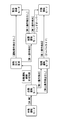
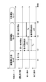
- FIG. 1 is a block diagram showing an overall image of a configuration related to automatic driving mounted on a vehicle.
- FIG. 2 is a diagram illustrating an example of specific configurations of the automatic operation ECU, the HCU, and the vehicle control ECU.
- FIG. 3 is a state transition diagram showing an overall image of the transition of the operation mode performed in the driving change control unit,
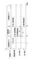
- FIG. 4 is a time chart showing a transition when a driving change is performed by an override.
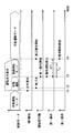
- FIG. 5 is a time chart showing a transition when a driving change is performed by a handover, FIG.
- FIG. 6 is a flowchart showing details of the driving change control process for realizing the driving change by the override
- FIG. 7 is a flowchart showing details of the driving change control process for realizing the driving change by handover
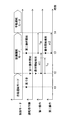
- FIG. 8 is a time chart showing the transition when the driving change is performed by overriding in the second embodiment.
- FIG. 9 is a flowchart showing details of the driving change control process for realizing the driving change by the override of FIG.
- FIG. 10 is a time chart showing the transition when the driving change is performed by handover in the second embodiment.
- FIG. 11 is a flowchart showing details of the driving change control process for realizing the driving change by the handover of FIG. FIG.
- FIG. 12 is a block diagram showing an overall image of a configuration related to automatic driving in the third embodiment
- FIG. 13 is a state transition diagram showing an overall image of the transition of the operation mode performed in the operation change control unit of the third embodiment.
- FIG. 14 is a time chart showing a transition when the driving change is performed by overriding in the third embodiment
- FIG. 15 is a time chart showing a transition when the driving change is performed by overriding in the fourth embodiment.
- the function of the driving change control device is realized by an automatic driving ECU (Electronic Control Unit) 50 shown in FIGS. 1 and 2.
- the automatic operation ECU 50 is mounted on the vehicle A together with an electronic control unit such as an HCU (HMI (Human Machine Interface) Control Unit) 20 and a vehicle control ECU 80.
- the automatic driving ECU 50, the HCU 20, and the vehicle control ECU 80 are directly or indirectly electrically connected to each other and can communicate with each other.
- the vehicle A has an automatic driving function by the operation of the automatic driving ECU 50 and the vehicle control ECU 80.
- the HCU 20 controls the acquisition of input information to the operation system such as a steering switch and the presentation of information to the driver in an integrated manner.
- the HCU 20 is mainly configured by a computer having a main processor 21, a graphic processor 22, a RAM 23, a storage medium 24, and an input / output interface 25.
- the HCU 20 is electrically connected to a plurality of notification devices 10 that notify information to the driver.
- the notification device 10 notifies various information related to the vehicle A to the passengers of the vehicle A including the driver based on the notification control signal output by the HCU 20.
- the notification device 10 may be configured to be mounted in advance on the vehicle A, or may be configured to be temporarily mounted on the vehicle A by being brought into the passenger compartment by a passenger of the vehicle A.
- the notification device 10 includes, for example, a display device 11 that notifies information by display, a speaker device 12 that notifies information by notification sound, message sound, and the like.
- the HCU 20 constructs the information acquisition unit 31 and the notification control unit 32 as functional blocks by executing the notification control program stored in the storage medium 24 by the processors 21 and 22.
- the information acquisition unit 31 acquires various information from the automatic driving ECU 50 and the vehicle control ECU 80. As an example, the information acquisition unit 31 acquires change request information for requesting a driver to change driving from the automatic driving function.
- the notification control unit 32 generates a notification control signal to be output to the display device 11 and the speaker device 12 based on the information acquired by the information acquisition unit 31.
- the notification control unit 32 controls display and information presentation by sound by outputting a notification control signal directed to the display device 11 and the speaker device 12.
- the notification control unit 32 performs a notification requesting the driver to take over the driving operation from the automatic driving function using the display device 11 and the speaker device 12. .
- the vehicle control ECU 80 is electrically connected directly or indirectly to the vehicle-mounted actuator group 90 mounted on the vehicle A.
- the vehicle control ECU 80 is directly or indirectly electrically connected to a sensor group that detects a driving operation performed by the driver.
- the in-vehicle actuator group 90 includes, for example, a throttle actuator of an electronically controlled throttle, an injector, a brake actuator, a motor generator for driving and regeneration, a steering actuator, and the like.
- the sensor group includes an accelerator position sensor 44, a brake operation amount sensor 45, a steering angle sensor 46, a detection switch 47, and the like.
- the accelerator position sensor 44 detects the stroke amount of the accelerator pedal 14.
- the brake operation amount sensor 45 is a brake pedal force sensor that detects the pedal force input to the brake pedal 15.
- the steering angle sensor 46 detects the rotation angle of the steering wheel 16.
- a steering torque sensor that detects the steering torque input to the steering wheel 16 may be provided in place of or together with the steering angle sensor 46.
- the detection switch 47 detects an operation input to the turn signal lever 17. Each sensor and switch 47 outputs operation information that detects the driving operation to the automatic driving ECU 50 and the vehicle control ECU 80.
- the accelerator pedal 14, the brake pedal 15, the steering wheel 16, and the turn signal lever 17 described above are configured as operation targets for driving operation.
- the vehicle control ECU 80 is mainly configured by a computer having a processor 81, a RAM 83, a storage medium 84, an input / output interface 85, and the like.
- the vehicle control ECU 80 executes the vehicle control program stored in the storage medium 84 by the processor 81, thereby constructing the driving information acquisition unit 80a and the actuator control unit 80b as functional blocks related to vehicle control.
- the driving information acquisition unit 80a obtains vehicle control information output from the automatic driving ECU 50 and operation information output from the sensor group in addition to driving state information (described later) indicating the operating state of automatic driving. It can be acquired as information used for behavior control.
- the actuator control unit 80b generates a control signal output from the vehicle control ECU 80 toward the in-vehicle actuator group 90 based on at least one of the vehicle control information and the operation information acquired by the driving information acquisition unit 80a.
- the automatic operation ECU 50 is directly or indirectly electrically connected to the GNSS receiver 71, the map database 72, the camera unit 73, the lidar 74, the millimeter wave radar 75, and the like.
- the automatic driving ECU 50 acquires information related to the traveling environment around the host vehicle necessary for automatic driving from these configurations (71 to 75).
- a GNSS (Global Navigation Satellite System) receiver 71 receives positioning signals from a plurality of artificial satellites.
- the GNSS receiver 71 measures the current position of the vehicle A based on the received positioning signal.
- the GNSS receiver 71 sequentially outputs the measured position information of the vehicle A to the automatic operation ECU 50.
- the map database 72 is a storage medium that stores a large number of map data.
- the map data includes structural information such as the curvature, slope, and section length of each road, and non-temporary traffic regulation information such as speed limit and one-way traffic.
- the map database 72 causes the automatic driving ECU 50 to acquire map data around the current position of the vehicle A and the traveling direction.
- the camera unit 73, the lidar 74, and the millimeter wave radar 75 are stationary objects such as moving objects such as pedestrians and other vehicles, falling objects on the road, traffic signals, guardrails, curbs, road signs, road markings, and marking lines. It is an autonomous sensor that detects an object.
- the camera unit 73, the lidar 74, and the millimeter wave radar 75 sequentially output detected object information relating to the detected moving object and stationary object to the automatic operation ECU 50.
- the camera unit 73 includes a monocular or compound-eye front camera that captures a front area of the vehicle A, and an image processing unit that analyzes an image of the front area captured by the front camera.
- the camera unit 73 acquires detected object information by extracting a moving object and a stationary object that appear in the image of the front area.
- the lidar 74 irradiates the laser beam in the traveling direction of the vehicle A, and acquires the detected object information by receiving the laser beam reflected by the moving object and the stationary object existing in the traveling direction.
- the millimeter wave radar 75 irradiates the millimeter wave toward the traveling direction of the vehicle A, and acquires the detected object information by receiving the millimeter wave reflected by a moving object and a stationary object existing in the traveling direction.
- the millimeter wave radar 75 can detect an object farther than the lidar 74.
- the automatic driving ECU 50 performs an acceleration / deceleration control and a steering control of the vehicle A in cooperation with the vehicle control ECU 80, thereby exhibiting an automatic driving function capable of performing the driving operation of the vehicle A on behalf of the driver.
- the automatic operation ECU 50 is mainly configured by a computer having a main processor 51, a graphic processor 52, a RAM 53, a storage medium 54, and an input / output interface 55.
- the automatic operation ECU 50 can execute the automatic operation program and the operation change program stored in the storage medium 54 by the respective processors 51 and 52.
- the automatic driving ECU 50 functions the driving environment recognition unit 61, the driving plan generation unit 62, the driving change control unit 63, the ECU communication unit 64, and the HCU communication unit 65 for automatic driving. Build as.
- the traveling environment recognition unit 61 recognizes the traveling environment of the vehicle A by combining the position information acquired from the GNSS receiver 71, the map data acquired from the map database 72, the detected object information acquired from each autonomous sensor, and the like. .
- the traveling environment recognizing unit 61 recognizes the shape and moving state of the object around the vehicle A based on the integration result of the detected object information, and combines the position information and the map data, particularly within the detection range of each autonomous sensor. Thus, a virtual space that reproduces the actual driving environment in three dimensions is generated.
- the travel plan generation unit 62 generates a travel plan for automatically driving the vehicle A by an automatic driving function based on the travel environment recognized by the travel environment recognition unit 61.
- a long-term travel plan and a short-term travel plan are generated.
- a route for directing the vehicle A to the destination set by the driver is defined.
- a schedule of planned driving change from the automatic driving function to the driver is set mainly based on a long-term driving plan.
- a planned travel locus for realizing travel according to the long- and medium-term travel plan is defined using the virtual space around the vehicle A generated by the travel environment recognition unit 61. Specifically, execution of steering for lane tracking and lane change, acceleration / deceleration for speed adjustment, and sudden braking for collision avoidance is determined based on a short-term travel plan.
- the driving change control unit 63 controls switching of the control right related to the driving operation between the automatic driving function and the driver.
- the driving change control unit 63 starts the operation of the automatic driving function by detecting the switching operation to the automatic driving by the driver in the area where the automatic driving is possible.
- the driving change control unit 63 refers to the long-term driving plan, and systematically switches from automatic driving to manual driving by the driver before the area where automatic driving can be completed.
- the driving change control unit 63 is configured to perform manual operation from automatic driving even when it is difficult to recognize the driving environment by the driving environment recognition unit 61 accidentally or suddenly and it is difficult to generate a short-term driving plan by the driving plan generation unit 62. Switch to driving.
- the ECU communication unit 64 performs an output process of information directed to the vehicle control ECU 80 and an acquisition process of information from the vehicle control ECU 80. Specifically, the ECU communication unit 64 generates vehicle control information instructing acceleration / deceleration and steering in accordance with the planned travel locus formulated by the travel plan generation unit 62, and displays driving state information ( And output sequentially to the vehicle control ECU 80. Further, the ECU communication unit 64 can sequentially acquire state information indicating the control state of the in-vehicle actuator group 90 from the vehicle control ECU 80, and can correct the content of the vehicle control information.
- the ECU communication unit 64 has an operation information acquisition block 64a as a sub-function block.
- the operation information acquisition block 64a acquires signals output from the accelerator position sensor 44, the brake operation amount sensor 45, the steering angle sensor 46, and the detection switch 47 as operation information related to the driving operation input by the driver. .
- the operation information is provided to the driving change control unit 63 and used when changing driving from the automatic driving function to the driver.
- the HCU communication unit 65 performs information output processing to the HCU 20 and information acquisition processing from the HCU 20.
- the HCU communication unit 65 has a driving change request block 65a as a sub-function block.
- the driving change request block 65 a generates change request information for requesting a driving change from the automatic driving function to the driver based on the driving change schedule generated by the driving change control unit 63, and outputs it to the HCU 20.
- the driving change request block 65a requests the driver to change driving by controlling the notification device 10 in cooperation with the HCU 20.
- the driving change control unit 63 includes a driving state switching block 63a and an operation detection block 63b as sub function blocks for controlling switching from automatic driving to manual driving. First, the functions of these sub-function blocks will be described with reference to FIGS.
- the driving state switching block 63a switches the driving mode of the vehicle A among a plurality of preliminarily defined by the control for changing the operation state of the automatic driving function (see FIG. 3).
- the plurality of operation modes switched by the operation state switching block 63a includes at least a cooperative operation mode and an automatic evacuation mode in addition to the manual operation mode and the normal automatic operation mode.
- the driving mode currently set in the driving state switching block 63a is notified to the information acquisition unit 31 of the HCU 20 and the driving information acquisition unit 80a of the vehicle control ECU 80 as driving state information.
- the automatic operation function is stopped and the driver controls the traveling of the vehicle A.
- the vehicle control ECU 80 that is acquiring the driving state information indicating that it is in the manual driving mode generates a control signal in accordance with the operation information acquired from each of the sensors 44 to 46 by the actuator control unit 80b and sends it to the vehicle-mounted actuator group 90. Output.
- the automatic driving function in operation controls the traveling of the vehicle A.
- the vehicle control ECU 80 that is acquiring the driving state information indicating that it is in the automatic driving mode generates a control signal in accordance with the vehicle control information acquired from the automatic driving ECU 50 in the actuator control unit 80b, toward the in-vehicle actuator group 90. Output.
- the cooperative operation mode is a specific aspect of the automatic operation mode, and the automatic operation function is activated.
- the traveling of the vehicle A is controlled by coordinating the control by the automatic driving function and the driving operation by the driver.
- the vehicle control ECU 80 that is acquiring the driving state information indicating that it is in the cooperative driving mode outputs a control signal having contents based on both the operation information acquired from each of the sensors 44 to 46 and the vehicle control information acquired from the automatic driving ECU 50. Generated and output toward the in-vehicle actuator group 90.
- the actuator control unit 80b when the driving force indicated by the driving state information and the driving force indicated by the operation information are different from each other, the actuator control unit 80b outputs a control signal having a content according to one of the two driving forces having a larger value. Generate. Similarly, when the braking force indicated by the driving state information and the braking force indicated by the operation information are different from each other, the actuator control unit 80b generates a control signal having a content according to one of the two braking forces having a larger value. To do. If the steering target value indicated by the driving state information is different from the actual steering angle indicated by the operation information, the actuator control unit 80b causes the actual steering angle to approach the steering target value indicated by the driving state information. The control signal for increasing or decreasing the torque of the steering actuator is output.
- the automatic evacuation mode is another aspect of the automatic operation mode, and the automatic operation function is activated.
- the automatic evacuation mode is performed when the control right transfer from the automatic driving function to the driver is not performed in a desirable state.
- the vehicle A in the automatic evacuation mode automatically travels to the stop position searched by the automatic operation ECU 50 and stops at the reached stop position.
- the vehicle control ECU 80 that is acquiring the driving state information indicating the automatic evacuation mode basically ignores the operation information acquired from each of the sensors 44 to 46, and controls the content according to only the vehicle control information acquired from the automatic driving ECU 50. Output a signal.
- the operation detection block 63b detects a driver's driving operation related to handover and override of the control right based on the operation information acquired by the operation information acquisition block 64a in the vehicle A in which the automatic driving function is operating. To do.
- the handover requests the driver to change driving, and the driver performs the driving operation in response to the request. It is a driving change of the form transferred to.
- the override is a driving change in which the control right is transferred to the driver when the driver performs the driving operation with his / her own intention when the vehicle A is traveling by the automatic driving function.
- Handover is the transfer of authority from the automatic driving function to the driver based on the judgment of the system.
- the override is an authority transfer from the automatic driving function to the driver based on the judgment of the driver.
- the operation detection block 63b A second operation is detected.
- the operation detection block 63b stores, for each operation target, an operation amount threshold value and a time threshold value that define an operation amount and an operation duration time for determining whether the first operation and the second operation are present. Based on the operation information, the operation detection block 63b detects a driving operation that exceeds both the operation amount threshold and the time threshold as a first operation or a second operation.
- the operation detection block 63b detects, as the first operation, a driving operation that is reflexively performed by the driver in response to an event that may interfere with the traveling of the vehicle A.
- the first operation is a driving operation that is estimated to have been input by the driver.
- a driving operation performed after the first operation and different from the first operation is detected as the second operation.
- the second operation is a driving operation presumed to have been performed after the driver's intention to drive was recovered.
- the operation detection block 63b detects, as the second operation, a driving operation that is performed after about 0.5 second has elapsed since the detection determination of the first operation is performed.
- the operation target to which the first operation and the second operation are input may be the same or different.
- the operation detection block 63b may detect a driving operation of stepping on the brake pedal 15 as a first operation, and detect a driving operation of steering the steering wheel 16 as a second operation. As described above, the operation detection block 63b can detect, as the second operation, a driving operation for an operation target different from the operation target to which the first operation is input.
- the operation detection block 63b may detect a driving operation that strongly depresses the brake pedal 15 as the first operation, and detect a driving operation that adjusts the depression force of the brake pedal 15 as the second operation. As described above, the operation detection block 63b can detect, as the second operation, a driving operation with respect to the operation target to which the first operation is input and having a smaller operation amount than the first operation.
- the operation state switching block 63a switches the operation mode from the manual operation mode to the normal automatic operation mode based on an input to a switch that instructs the start of automatic operation provided in an operation system such as a steering switch.
- a switch that instructs the start of automatic operation provided in an operation system such as a steering switch.
- the operation amount threshold and the time threshold are exceeded.
- a driving operation is input by the driver (time t2).
- the driving state switching block 63a switches the driving mode from the automatic driving mode to the cooperative driving mode.
- the driving operation is detected as the second operation by the operation detection block 63b. (Time t3). Based on the detection of the second operation, the operation state switching block 63a switches the operation mode from the cooperative operation mode to the manual operation mode. In the first embodiment, when it is determined that the second operation has been detected, switching of the operation state from the cooperative operation mode to the manual operation mode is immediately started. Thus, the override by the driver is completed.
- a predetermined restart waiting period for example, 3
- the driving state switching block 63a switches the driving mode from the cooperative driving mode to the automatic driving mode.
- the vehicle A resumes traveling by the automatic driving function without any special operation by the driver.
- the automatic driving is not canceled and the side far from the large vehicle in the traveling lane by steering operation It is possible to bring the vehicle A to the vehicle temporarily.
- the driving state switching block 63a ends the driving change request and switches from the cooperative driving mode to the manual driving mode.
- the switching of the driving state from the cooperative driving mode to the manual driving mode is immediately started without a waiting time being triggered by the determination that the second operation is detected. Thus, the handover by the driver is completed.
- the driving state switching block 63a after the transition to the cooperative operation mode based on the driving change request, when the predetermined required execution time elapses without the second operation being detected, the driving state switching block 63a is Then, the cooperative operation mode is switched to the automatic evacuation mode. Similarly, after executing the driving change request, even when a predetermined request execution time has elapsed without any driving operation being detected, the driving state switching block 63a performs the transition to the automatic evacuation mode. As a result, the vehicle A sequentially starts the search for the stop position and the movement to the stop position by cooperative control of the automatic operation ECU 50 and the vehicle control ECU 80. Such control functions effectively when the driver is in a difficult driving state.
- the requested execution time is set so that the vehicle A does not go out of the automatic driving area without changing to the manual driving mode, and is set to about 4 seconds, for example.
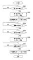
- the driving change control process shown in FIGS. 6 and 7 is started by the driving change control unit 63 based on the switching from the manual operation mode to the automatic operation mode.
- S101 operation information related to the driving operation input by the driver is acquired, and the first operation is detected based on the acquired operation information. If the first operation is detected in S101, the process proceeds to S102. On the other hand, if the first operation cannot be detected, the detection determination in S101 is continued. When it is not the manual operation mode, the detection determination in S101 is continuously performed.
- a timer for measuring the duration of the first operation which starts counting a timer et1 from the time t2 (see FIG. 4) at which the first operation is detected, is started, and the process proceeds to S103.
- the operation mode of the vehicle A is switched from the automatic operation mode to the cooperative operation mode (see time t2 in FIG. 4), and the process proceeds to S104 (see time t2 in FIG. 4).
- S104 it is determined whether or not the elapsed time et1 of the timer that started counting in S102 exceeds a reference value. For example, the above-described intention recovery time of 0.5 seconds is applied to the reference value. In S104, the determination is repeated until the elapsed time et1 exceeds the reference value. When the elapsed time et1 exceeds the reference value, the process proceeds to S105.
- S105 the input of the second operation by the driver is detected based on the operation information. If the second operation is detected in S105, the process proceeds to S106. On the other hand, if the second operation cannot be detected, the detection determination in S105 is continued. In S106, based on the detection determination of the second operation in S105, the operation mode of the vehicle A is switched from the cooperative operation mode to the manual operation mode (see time t3 in FIG. 4), and the operation change control process is ended.
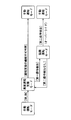
- S111 it is determined whether or not it is time to execute a driving change request to the driver based on the long-term driving plan. The determination in S111 is repeated until the execution timing of the driving change request is reached. If it is determined in S111 that it is the execution timing of the driving change request, the process proceeds to S112. In S112, a request for driving change is started (see time t1 in FIG. 5), and the process proceeds to S113.
- S113 similarly to S101 (see FIG. 6), the first operation is detected and determined, and the process proceeds to S114 based on the detection of the first operation.
- S114 the timer counting the elapsed time et1 from the time t3 (see FIG. 5) at which the first operation is detected is started, and the process proceeds to S115.
- S115 based on the detection determination of the first operation in S114, the operation mode of the vehicle A is switched from the automatic operation mode to the cooperative operation mode (see time t3 in FIG. 5), and the process proceeds to S116.
- S116 similarly to S104 (see FIG. 6), it is determined whether or not the elapsed time et1 of the timer exceeds a reference value (for example, 0.5 seconds), and based on the elapsed time et1 exceeding the reference value, S117 Proceed to In S117, detection determination of the second operation is performed similarly to S105 (see FIG. 6), and the process proceeds to S118 based on the determination result that the second operation is detected.
- the operation mode of the vehicle A is switched from the cooperative operation mode to the manual operation mode (see time t4 in FIG. 5), and the driving change control process is ended.
- switching from the cooperative operation mode to the manual operation mode is performed when it is determined that there is an input of the second operation detected after the first operation instead of the first operation.
- the Therefore it is possible to prevent a situation in which the operation mode is switched to the manual operation mode based on the driving operation performed reflexively and the driving operation continued without regaining the intention to drive.
- the automatic driving ECU 50 can switch to the manual driving mode after the driver can reflect his intention in the driving operation.
- switching of the operation state from the cooperative operation mode to the manual operation mode is started at substantially the same timing as the detection of the second operation, based on the edge of the second operation detection determination.
- the automatic driving ECU 50 can quickly return the control right of the driving operation to the driver who has regained the intention of driving.
- the operation detection block 63b of the first embodiment can detect a driving operation input to the same operation target as the first operation and having a smaller operation amount than the first operation as the second operation. .
- the driver notices that the operation amount of the driving operation (first operation) input in response to the generated event is excessive, and performs the driving operation to adjust the operation amount to be small.
- the driver who performs the driving operation for adjusting the operation amount has recovered to a state in which his / her intention can be reflected in the driving operation. Therefore, if the driving operation for reducing the operation amount is detected as the second operation, it is possible to reliably deliver the control right of the driving operation to the driver in a state where the intention can be reflected in the driving operation.
- the operation detection block 63b of the first embodiment can detect a driving operation for an operation target different from the operation target to which the first operation is input as the second operation. In this way, at the stage where the driving operation is performed on a plurality of operation objects, the driver is highly likely to have already regained the intention to drive the operation. Therefore, if the driving operation for the operation target different from the first operation can be detected as the second operation, the driving change control unit 63 reliably delivers the control right of the driving operation to the driver who can reflect the intention in the driving operation. It becomes possible.
- the operation detection block 63b of the first embodiment detects, as the second operation, the driving operation performed after the elapse of the intention recovery time from when the detection determination of the first operation is performed.
- the operation detection block 63b of the first embodiment detects, as the second operation, the driving operation performed after the elapse of the intention recovery time from when the detection determination of the first operation is performed.
- the driving mode when an intentional driving operation is not input after the driving change request, the driving mode is not switched to the manual driving mode but is switched to the automatic evacuation mode. According to such control, the situation where the driving change to the driver who has not regained the intention of driving operation is reliably avoided.
- the automatic driving ECU 50 can continue the automatic driving. Therefore, when there is no request for driving change, after switching to the cooperative driving mode, if the second operation is not detected, the automatic driving mode may be returned. Even with such control, a situation in which the control right is handed over to the driver who does not intend to perform the driving operation is avoided.
- the automatic operation ECU 50 corresponds to the “drive change control device”, and the main processor 51 and the graphic processor 52 correspond to the “processing unit”.
- the driving state switching block 63a corresponds to the “driving state switching unit”
- the operation detection block 63b corresponds to the “operation detection unit”
- the operation information acquisition block 64a corresponds to the “operation information acquisition unit”
- the request block 65a corresponds to a “driving change request unit”.
- the automatic operation mode corresponds to “automatic operation state”
- the manual operation mode corresponds to “manual operation state”
- the cooperative operation mode corresponds to “cooperative operation state”
- the automatic retraction mode is “automatic retraction state”. It corresponds to.
- the second embodiment of the present disclosure shown in FIGS. 8 to 11 is a modification of the first embodiment.
- the operation state switching block 63a (see FIG. 1) of the second embodiment is detected after the second operation is detected, when the second operation continues beyond a preset switching standby time tde, Start switching of the operation mode from the cooperative operation mode to the manual operation mode.
- the switching standby time tde may be set to substantially the same time as the intention recovery time tre, for example, about 0.5 seconds.
- the transition to time t3 is substantially the same as in the first embodiment (see FIG. 4).
- this driving operation is detected as the first operation at time t2.
- the driving state switching block 63a switches the driving mode from the automatic driving mode to the cooperative driving mode.
- the driving operation is Detected as an operation. Then, at time t4 when the second operation continues beyond the reference value, the operation state switching block 63a switches the operation mode from the cooperative operation mode to the manual operation mode.
- the above-described switching standby time tde (about 0.5 seconds) is used.
- S201 to S205 in the flowchart shown in FIG. 9 are substantially the same as S101 to S105 (see FIG. 6) of the first embodiment, and in S203, switching to the cooperative operation mode is performed.
- S206 when the second operation is detected in S205, a timer that measures the duration time of the second operation and that measures an elapsed time et2 from time t3 (see FIG. 8) at which the second operation is detected. Is started, and the process proceeds to S207.
- S207 it is determined whether or not the elapsed time et2 of the timer that started counting in S206 has exceeded the switching standby time tde that is a reference value. In S207, the determination is repeated until the elapsed time et2 exceeds the reference value. If the elapsed time et2 exceeds the reference value, the process proceeds to S208. In S208, the operation mode of vehicle A is switched from the cooperative operation mode to the manual operation mode (see time t4 in FIG. 8), and the driving change control process is terminated.
- the transition to time t3 is substantially the same as in the first embodiment (see FIG. 5).
- the driver's awareness is generated at time t2, and then the driving operation by the driver is input.
- the This driving operation is detected as the first operation at time t3, and the driving state switching block 63a switches to the cooperative driving mode.
- this driving operation is set as the second operation. Detected.
- the operation state switching block 63a switches the operation mode from the cooperative operation mode to the manual operation mode at time t5 when the second operation has continued beyond the switching standby time tde that is the reference value.
- S 11 are substantially the same as S111 to S117 (see FIG. 7) of the first embodiment, and in S215, switching to the cooperative operation mode is performed.
- S218 when the second operation is detected in S217, the timer for counting the elapsed time et2 from the time t4 (see FIG. 10) when the second operation is detected is started, and the process proceeds to S219.
- S219 it is determined whether or not the elapsed time et2 of the timer that started counting in S218 has exceeded the switching standby time tde that is a reference value. In S219, the determination is repeated until the elapsed time et2 exceeds the reference value, and when the elapsed time et2 exceeds the reference value, the process proceeds to S220. In S220, the operation mode of vehicle A is switched from the cooperative operation mode to the manual operation mode (see time t5 in FIG. 10), and the driving change control process is terminated.
- the switching of the operation state from the cooperative operation mode to the manual operation mode is started at the timing when the second operation continues beyond the switching standby time tde.
- the switching standby time tde has elapsed, not immediately after detection of the second operation, for example, when the first operation is input, another operation target is not intended. It is possible to prevent the driver from changing when he / she touches.
- the automatic driving ECU 50 can reliably deliver the control right of the driving operation to the driver who can reflect the intention in the driving operation.
- the third embodiment of the present disclosure shown in FIGS. 12 to 14 is another modification of the first embodiment.
- the automatic driving function installed in the vehicle A of the third embodiment is a semi-automatic driving function realized by a so-called advanced driving support system.
- the advanced driving support system is a system that presupposes that the driver can operate at any time even during the operation of the automatic driving function by the system.
- the advanced driving support system determines that the driving support cannot be continued, the driving state is changed to the manual driving mode without the driving change request as in the above embodiment.
- the advanced driving support system can execute a plurality of acceleration, steering, and braking of the vehicle A.
- the driving change request based on the long-term driving plan is not executed.
- the function of the driving shift control device in the vehicle A equipped with such an advanced driving support system is realized by a vehicle control ECU 180 shown in FIG.
- the vehicle control ECU 180 includes a part of the function of the automatic operation ECU 50 (see FIG. 1) of the first embodiment, and enables the vehicle A to run semi-automatically.
- the vehicle control ECU 180 includes a driving information acquisition unit 180a, an ADAS function unit 161, and a driving shift control unit 163 as functional blocks, and an actuator control unit 80b and an HCU communication unit 65 that are substantially the same as those in the first embodiment.
- the driving information acquisition unit 180a has the function of the operation information acquisition block 64a (see FIG. 1) of the first embodiment.
- the operation information acquisition unit 180a acquires operation information output from the sensors 44 to 46 and the detection switch 47.
- the operation information is provided to the driving change control unit 163 and used when driving is changed from the automatic driving function to the driver.
- the ADAS (Advanced Driving Assistant System) function unit 161 includes a target recognition block 161a, an ACC (Adaptive Cruise Control) function block 161b, and an LTC (Lane Trace Control) function block 161c as sub function blocks.
- the target recognition block 161a detects the relative position of the moving object and the stationary object in the traveling direction by integrating the detected object information acquired from the camera unit 73, the lidar 74, and the millimeter wave radar 75. For example, the target recognition block 161a can recognize a preceding vehicle, a lane marking, and the like.
- the ACC function block 161b adjusts the driving force and the braking force in cooperation with the actuator control unit 80b based on the relative position information of the moving object and the stationary object recognized by the target recognition block 161a. It is a functional unit that controls the traveling speed. Specifically, the ACC function block 161b cruises the vehicle A at the target speed set by the driver when the preceding vehicle is not detected. When the preceding vehicle is detected, the ACC function block 161b causes the vehicle A to follow the preceding vehicle while maintaining the inter-vehicle distance to the preceding vehicle.
- the LTC function block 161c adjusts the steering force in cooperation with the actuator control unit 80b based on the shape information of the lane markings in the traveling direction acquired from the target recognition block 161a, thereby adjusting the steering angle of the steered wheels of the vehicle A. It is a functional part to control.
- the LTC function block 161c causes the vehicle A to travel so as to follow the traveling lane.
- the driving change control unit 163 determines the driver's intention to override and stops the operation of the ADAS function unit 161 that realizes the advanced driving support system.
- the driving change control unit 163 includes an operation detection block 63b and an operating state switching block 63a as in the first embodiment.
- the operation detection block 63b detects the driving operation of the driver as related to the override based on the operation information acquired by the driving information acquisition unit 180a.
- the driving state switching block 63a switches the driving mode among the manual driving mode, the advanced driving support mode, and the cooperative driving mode. As shown in FIG. 12 to FIG. 14, the driving state switching block 63a is operated from the manual driving mode to the advanced driving support mode based on an input to a switch instructing the operation of ACC or LTC provided in an operation system such as a steering switch. The operation mode is switched to (see FIG. 13). In the advanced driving support mode, at least one of the ACC function block 161b and the LTC function block 161c functions.
- the driving operation is input by the driver (see time t2 in FIG. 14). Based on the detection of this driving operation as the first operation, the driving state switching block 63a switches the driving mode from the advanced driving support mode to the cooperative driving mode.
- the driver's driving operation is further input after the elapsed time et1 exceeds the intention recovery time tre due to the continuation of the first operation, this driving operation is detected as the second operation. (See FIG. 14, time t3). Based on the detection of the second operation, the operation state switching block 63a switches the operation mode from the cooperative operation mode to the manual operation mode. Thus, the override by the driver is completed.
- the override of the third embodiment can be realized by substantially the same driving change control process (see FIG. 7) as the first embodiment.
- the driving change control unit 163 switches the operation mode from the cooperative operation mode to the advanced driving support mode. To return.
- the ADAS function unit 161 determines that the automatic driving cannot be continued in the advanced driving support mode, the ADAS function unit 161 automatically stops the ACC function block 161b and the LTC function block 161c. As described above, the operation mode is switched to the manual operation mode.
- the vehicle control ECU 180 corresponds to the “driving change control device”
- the driving information acquisition unit 80a corresponds to the “operation information acquisition unit”
- the advanced driving support mode corresponds to the “automatic driving state”. To do.
- the fourth embodiment of the present disclosure illustrated in FIG. 15 is a modification of the third embodiment.
- the operation state switching block 63a (see FIG. 12) of the fourth embodiment is manually operated from the cooperative operation mode when the second operation is continued beyond a preset switching standby time tde. Start switching to operation mode.
- the transition of the override in the fourth embodiment is substantially the same as in the second embodiment (see FIG. 5). Specifically, when the driver notices at time t1 and a driving operation is input, this driving operation is detected as the first operation at time t2. Based on the detection determination of the first operation described above, the driving state switching block 63a switches the driving mode from the advanced driving support mode to the cooperative driving mode.
- the driving operation is further input at time t3 after the intention recovery time tre (about 0.5 seconds) is exceeded and the first operation is continued after switching to the cooperative driving mode, the driving operation is changed to the second operation. Detected as Then, at time t4 when the second operation has continued beyond the switching standby time tde (about 0.5 seconds), the operation state switching block 63a switches the operation mode from the cooperative operation mode to the manual operation mode. . Thus, the override by the driver is completed.
- the override of the fourth embodiment can be realized by the operation change control process (see FIG. 9) that is substantially the same as that of the second embodiment.
- the operation target of the first operation that is a trigger for switching to the cooperative operation mode is limited to the accelerator pedal, the brake pedal, and the steering wheel.
- the operation target of the second operation to the manual operation mode is not limited to the operation target of the first operation, and may include a turn signal lever, a shift lever, a shift paddle, and the like.
- the driving operation detected as the second operation may be limited to the driving operation input to the operation target different from the operation target input to the first operation. That is, a driving operation that adjusts the depression force of the accelerator pedal and the brake pedal may not be detected as the second operation. Further, whether or not to provide a switching standby time may be set according to the type of operation target to which the second operation is input.
- the driving operation detected as the second operation is limited to the driving operation after the input of the first operation has continued for the intention recovery time (about 0.5 seconds) or longer.
- the specific length of the intention recovery time may be adjusted as appropriate.
- the operation detection block can detect, for example, a driving operation after a predetermined intention recovery time (for example, 2.5 seconds) has elapsed since the start time of the driving change request (see time t1 in FIG. 5) as the second operation. It may be.
- switching to the manual operation mode is started immediately with the detection edge of the second operation as a trigger.
- a predetermined delay time may be set between the detection of the second operation and the start of switching. The length of the delay time may be changed as appropriate according to the traveling environment, the traveling state, and the like.
- the operation mode when the second operation is not detected after the transition to the cooperative operation mode, the operation mode is returned to the automatic operation mode or the altitude support mode.
- the cooperative operation mode may be continued until the second operation is detected.
- the driving mode when a driving operation is not detected after a driving change request, the driving mode is forcibly switched to the automatic evacuation mode.
- switching to the evacuation travel mode may not be performed.
- the vehicle A may be gradually stopped without searching for a stop position.
- the notification device that requests the driving change is not limited to the display device and the speaker device, and may be a tactile sense presentation device or the like.
- control using the second operation as a trigger for switching from the cooperative operation mode to the manual operation mode is also applied to a low-level automatic operation in which the driver is obliged to monitor even during the automatic operation. It is also applicable to high-level automated driving where no monitoring obligation is imposed.
- the function of the driving change control device may be realized by a configuration different from the automatic driving ECU 50 and the vehicle control ECU 180 described above.
- a processing unit provided in the HCU 20 or the like may implement the driving change control method according to the present disclosure.
- a processing unit of an electronic control unit that integrates two or more functions among the automatic driving ECU, the vehicle control ECU, and the HCU may implement the driving change control method according to the present disclosure.
- the processing units of a large number of electronic control units may cooperate to implement the driving change control method according to the present disclosure.
- each function related to driving change may be appropriately realized by various electronic control units mounted on the vehicle.
- various non-transitory physical storage media such as a flash memory and a hard disk can be adopted as a configuration for storing a driving change program executed by each processing unit.
- each unit is expressed as, for example, S101.
- each part can be divided into a plurality of sub-parts, while the plurality of parts can be combined into one part.
- each part configured in this manner can be referred to as a circuit, a device, a module, and a means.
- Each of the above-mentioned plurality of parts or a combination thereof is not only (i) a software part combined with a hardware unit (for example, a computer), but also (ii) hardware (for example, an integrated circuit, As a part of the (wiring logic circuit), it can be realized with or without including the functions of related devices.
- the hardware unit can be configured inside a microcomputer.
Abstract
This drive mode-switching control device comprises: operating information acquisition units (64a, 180a) which acquire operating information; a drive mode-switching unit (63a) which sets a plurality of drive modes including at least an automatic drive mode, a manual drive mode and an assisted drive mode, and switches between the plurality of drive modes; and an operation detection unit (63b) which, if the drive mode is not manual drive mode, detects, on the basis of operating information, the inputs of a first operation which is a driving operation of the driver, and a second operation which is a driving operation different from the first operation and which is performed after the first operation. The drive mode-switching unit switches the drive mode from automatic drive mode to assisted drive mode on the basis of the detection of the first operation, and switches the drive mode from the assisted drive mode to manual drive mode on the basis of the detection of the second operation.
Description
本出願は、2016年12月7日に出願された日本特許出願番号2016-237834号に基づくもので、ここにその記載内容を援用する。
This application is based on Japanese Patent Application No. 2016-237834 filed on Dec. 7, 2016, the contents of which are incorporated herein by reference.
この明細書による開示は、運転者と自動運転機能との間における運転交代を制御する運転交代制御装置、及び運転交代制御方法に関する。
The disclosure according to this specification relates to a driving shift control device that controls driving shift between a driver and an automatic driving function, and a driving shift control method.
近年、車両の運転操作を運転者に代わって実施可能な自動運転機能を備えた車両の開発が推し進められている。こうした車両では、運転者と自動運転機能との間における運転交代が実施される。一例として、車両が手動運転状態でない場合にて、運転者の運転操作が行われると、自動運転機能から運転者への運転交代が実施される。
In recent years, development of vehicles equipped with an automatic driving function capable of performing vehicle driving operations on behalf of a driver has been promoted. In such a vehicle, a driving change is performed between the driver and the automatic driving function. As an example, when the driving operation of the driver is performed when the vehicle is not in the manual driving state, the driving change from the automatic driving function to the driver is performed.
以上のような運転交代に関連する技術として、例えば特許文献1には、自動運転状態、手動運転状態、及び協調運転状態のうちで車両の運転状態を切り替える運転状態切替部を備えた自動運転車両システムが開示されている。この自動運転車両システムでは、自動運転状態である場合に、操作量が介入判定閾値以上かつ手動運転開始閾値未満となったとき、又は操作の継続カウントが第一閾値以上かつ第二閾値未満になったときに、協調運転状態へと運転状態が切り替えられる。さらに、操作量が手動運転開始閾値以上になったとき、又は操作の継続カウントが第二閾値以上になったときに、運転状態は、協調運転状態から手動運転状態へと切り替えられる。
As a technique related to the driving change as described above, for example, Patent Document 1 discloses an automatic driving vehicle including a driving state switching unit that switches a driving state of a vehicle among an automatic driving state, a manual driving state, and a cooperative driving state. A system is disclosed. In this automatic driving vehicle system, in the automatic driving state, when the operation amount is equal to or greater than the intervention determination threshold value and less than the manual driving start threshold value, or the operation continuation count is equal to or more than the first threshold value and less than the second threshold value. The driving state is switched to the cooperative driving state. Furthermore, when the operation amount is equal to or greater than the manual operation start threshold value or when the operation continuation count is equal to or greater than the second threshold value, the operation state is switched from the cooperative operation state to the manual operation state.
さて、本開示の発明者は、自動運転機能が車両の走行を制御する自動運転状態において、緊急回避を要するような状況が生じた場合に、運転者があわてて入力した操作には、運転者の意思が反映されていない点に着目した。こうした運転者の咄嗟の運転操作は、操作量が適切で無い場合が多くなる。故に、運転者が意思を持って操作量を適切に調整できる状態で手動運転状態に切り替える必要がある、と本開示の発明者は考えた。
Now, the inventor of the present disclosure provides the driver with an operation that is input by the driver when an emergency avoidance situation occurs in an automatic driving state in which the automatic driving function controls the traveling of the vehicle. We focused on the fact that no intention was reflected. There are many cases where the amount of operation is not appropriate for the driving operation of the driver's bag. Therefore, the inventor of the present disclosure thought that it is necessary to switch to the manual driving state in a state where the driver can appropriately adjust the operation amount with intention.
ここで、特許文献1の車両運転システムでは、運転操作の操作量が手動運転開始閾値以上になったとき、又は継続カウントが第二閾値以上になったときに、自動的に手動運転状態へと切り替えられる。そのため、反射的に行った過剰な操作量の運転操作、及び運転への意思を取り戻せないまま継続された運転操作等に基づき、手動運転状態へと切り替えられてしまう事態が生じ得た。以上のような運転交代が行われてしまうと、運転者が運転操作に意思を反映できない状態のまま、手動運転状態へと切り替る場合が発生し得た。
Here, in the vehicle driving system of Patent Document 1, when the operation amount of the driving operation becomes equal to or higher than the manual driving start threshold or when the continuation count becomes equal to or higher than the second threshold, the manual driving state is automatically entered. Can be switched. For this reason, there may have been a situation where the operation state is switched to the manual operation state based on the excessively manipulated operation operation performed reflexively and the operation operation continued without regaining the intention to drive. When the driving change as described above is performed, there may be a case where the driver switches to the manual driving state while the intention cannot be reflected in the driving operation.
本開示は、上記点に鑑みてなされたものであり、その目的は、運転者が運転操作に意思を反映できる状態となった後で、手動運転状態への切り替えを行うことが可能な運転交代制御装置及び運転交代制御方法を提供することにある。
The present disclosure has been made in view of the above points, and the purpose of the present disclosure is to change driving to a manual driving state after the driver can reflect his intention in the driving operation. A control device and an operation change control method are provided.
上記目的を達成するため、開示された一つの態様は、運転者に代わって運転操作を実施可能な自動運転機能を備える車両において、運転者と自動運転機能との間における運転交代を制御する運転交代制御装置であって、運転者によって入力される運転操作に関連した操作情報を取得する操作情報取得部と、自動運転機能が車両の走行を制御する自動運転状態、運転者が車両の走行を制御する手動運転状態、及び自動運転機能による制御と運転者による運転操作とを協調させて車両の走行が制御される協調運転状態、を少なくとも含む複数の運転状態を設定し、運転状態を複数のうちで切り替える運転状態切替部と、運転状態が手動運転状態でない場合にて、運転者の運転操作である第一操作、及び当該第一操作の後に実施され第一操作とは異なった運転操作である第二操作の各入力を、操作情報に基づいて検出する操作検出部と、を備え、運転状態切替部は、第一操作の検出判定に基づき運転状態を自動運転状態から協調運転状態へと切り替え、第二操作の検出判定に基づき運転状態を協調運転状態から手動運転状態へと切り替える運転交代制御装置とされる。
In order to achieve the above object, one disclosed aspect is a vehicle having an automatic driving function capable of performing a driving operation on behalf of the driver, and driving for controlling a driving change between the driver and the automatic driving function. The shift control device is an operation information acquisition unit that acquires operation information related to a driving operation input by a driver, an automatic driving state in which an automatic driving function controls driving of the vehicle, and the driver controls driving of the vehicle. A plurality of driving states including at least a manual driving state to be controlled, and a cooperative driving state in which the driving of the vehicle is controlled by coordinating the control by the automatic driving function and the driving operation by the driver. The first operation that is performed after the first operation and the first operation that is the driver's driving operation when the driving state is not the manual driving state, and the first operation that is performed after the first operation An operation detection unit that detects each input of the second operation that is a driving operation based on the operation information, and the driving state switching unit switches the driving state from the automatic driving state based on the detection determination of the first operation. The driving change control device is switched to the cooperative driving state and switches the driving state from the cooperative driving state to the manual driving state based on detection determination of the second operation.
また開示された一つの態様は、運転者に代わって運転操作を実施可能な自動運転機能を備える車両において、運転者と自動運転機能との間における運転交代を制御する運転交代制御方法であって、少なくとも一つの処理部により、運転者が車両の走行を制御する手動運転状態でない場合にて、運転者によって入力される運転操作に関連した操作情報を取得し、運転者の運転操作である第一操作を操作情報に基づいて検出し、第一操作の検出判定に基づいて、自動運転機能が車両の走行を制御する自動運転状態から、自動運転機能による制御と運転者による運転操作とを協調させて車両の走行が制御される協調運転状態へと、車両の運転状態を切り替え、第一操作の後に実施され第一操作とは異なった運転操作である第二操作の入力を操作情報に基づいて検出し、第二操作の検出判定に基づいて、運転状態を協調運転状態から手動運転状態へと切り替えることを含む、運転交代制御方法とされる。
One aspect disclosed is a driving change control method for controlling a driving change between a driver and an automatic driving function in a vehicle having an automatic driving function capable of performing a driving operation on behalf of the driver. The operation information related to the driving operation input by the driver is acquired by the at least one processing unit when the driver is not in the manual driving state for controlling the driving of the vehicle. One operation is detected based on the operation information, and based on the detection judgment of the first operation, the control by the automatic driving function and the driving operation by the driver are coordinated from the automatic driving state where the automatic driving function controls the driving of the vehicle The driving state of the vehicle is switched to the cooperative driving state in which the driving of the vehicle is controlled, and the input of the second operation that is performed after the first operation and is different from the first operation is input to the operation information. Detected on the basis of, on the basis of the detection and determination of the second operation includes switch the operating state from the cooperative operation state to the manual operation state, it is operated alternating control method.
これらの態様では、手動運転状態でない場合に、第一操作、及び第一操作の後に実施される第二操作の各入力が判定される。第一操作は、運転者があわてて入力した操作であると推定される。一方で、第二操作は、運転者が運転する意思を回復させたうえで実施した操作と推定され得る。
In these aspects, each input of the first operation and the second operation performed after the first operation is determined when not in the manual operation state. The first operation is presumed to be an operation input by the driver. On the other hand, the second operation can be estimated as an operation performed after the driver's intention to drive is recovered.
そして、これらの態様では、運転者による第二操作の入力があったと判定された場合には、協調運転状態から手動運転状態への切り替えが実施される。故に、反射的に行った運転操作及び運転への意思を取り戻せないまま継続された運転操作等に基づき、手動運転状態へと切り替えられてしまう事態は、防がれ得る。一方で、運転者が運転する意思を回復させたうえで第二操作を行えば、第二操作の入力判定に基づき、手動運転状態への切り替えが実施される。以上によれば、運転者が運転操作に意思を反映できる状態となった後で、手動運転状態への切り替えを行うことが可能となる。
In these modes, when it is determined that the driver has input the second operation, switching from the cooperative operation state to the manual operation state is performed. Therefore, it is possible to prevent a situation in which the operation state is switched to the manual operation state based on the driving operation performed reflexively and the driving operation continued without regaining the intention to drive. On the other hand, if the driver performs the second operation after recovering the intention to drive, switching to the manual operation state is performed based on the input determination of the second operation. According to the above, it becomes possible to switch to the manual driving state after the driver can reflect his intention in the driving operation.
本開示についての上記目的およびその他の目的、特徴や利点は、添付の図面を参照しながら下記の詳細な記述により、より明確になる。その図面は、
図1は、車両に搭載された自動運転に関連する構成の全体像を示すブロック図であり、
図2は、自動運転ECU、HCU、及び車両制御ECUの具体的な構成の一例を示す図であり、
図3は、運転交代制御部にて実施される運転モードの遷移の全体像を示す状態遷移図であり、
図4は、オーバーライドによって運転交代が行われる場合の推移を示すタイムチャートであり、
図5は、ハンドオーバーによって運転交代が行われる場合の推移を示すタイムチャートであり、
図6は、オーバーライドによる運転交代を実現するための運転交代制御処理の詳細を示すフローチャートであり、
図7は、ハンドオーバーによる運転交代を実現するための運転交代制御処理の詳細を示すフローチャートであり、
図8は、第二実施形態において、オーバーライドにより運転交代が行われる場合の推移を示すタイムチャートであり、
図9は、図8のオーバーライドによる運転交代を実現するための運転交代制御処理の詳細を示すフローチャートであり、
図10は、第二実施形態において、ハンドオーバーにより運転交代が行われる場合の推移を示すタイムチャートであり、
図11は、図11のハンドオーバーによる運転交代を実現するための運転交代制御処理の詳細を示すフローチャートであり、
図12は、第三実施形態にて自動運転に関連する構成の全体像を示すブロック図であり、
図13は、第三実施形態の運転交代制御部にて実施される運転モードの遷移の全体像を示す状態遷移図であり、
図14は、第三実施形態において、オーバーライドにより運転交代が行われる場合の推移を示すタイムチャートであり、
図15は、第四実施形態において、オーバーライドにより運転交代が行われる場合の推移を示すタイムチャートである。
The above and other objects, features and advantages of the present disclosure will become more apparent from the following detailed description with reference to the accompanying drawings. The drawing
FIG. 1 is a block diagram showing an overall image of a configuration related to automatic driving mounted on a vehicle. FIG. 2 is a diagram illustrating an example of specific configurations of the automatic operation ECU, the HCU, and the vehicle control ECU. FIG. 3 is a state transition diagram showing an overall image of the transition of the operation mode performed in the driving change control unit, FIG. 4 is a time chart showing a transition when a driving change is performed by an override. FIG. 5 is a time chart showing a transition when a driving change is performed by a handover, FIG. 6 is a flowchart showing details of the driving change control process for realizing the driving change by the override, FIG. 7 is a flowchart showing details of the driving change control process for realizing the driving change by handover, FIG. 8 is a time chart showing the transition when the driving change is performed by overriding in the second embodiment. FIG. 9 is a flowchart showing details of the driving change control process for realizing the driving change by the override of FIG. FIG. 10 is a time chart showing the transition when the driving change is performed by handover in the second embodiment. FIG. 11 is a flowchart showing details of the driving change control process for realizing the driving change by the handover of FIG. FIG. 12 is a block diagram showing an overall image of a configuration related to automatic driving in the third embodiment, FIG. 13 is a state transition diagram showing an overall image of the transition of the operation mode performed in the operation change control unit of the third embodiment. FIG. 14 is a time chart showing a transition when the driving change is performed by overriding in the third embodiment, FIG. 15 is a time chart showing a transition when the driving change is performed by overriding in the fourth embodiment.
以下、本開示の複数の実施形態を図面に基づいて説明する。尚、各実施形態において対応する構成要素には同一の符号を付すことにより、重複する説明を省略する場合がある。各実施形態において構成の一部分のみを説明している場合、当該構成の他の部分については、先行して説明した他の実施例の構成を適用することができる。また、各実施形態の説明において明示している構成の組み合わせばかりではなく、特に組み合わせに支障が生じなければ、明示していなくても複数の実施形態の構成同士を部分的に組み合わせることができる。そして、複数の実施形態及び変形例に記述された構成同士の明示されていない組み合わせも、以下の説明によって開示されているものとする。
Hereinafter, a plurality of embodiments of the present disclosure will be described with reference to the drawings. In addition, the overlapping description may be abbreviate | omitted by attaching | subjecting the same code | symbol to the corresponding component in each embodiment. When only a part of the configuration is described in each embodiment, the configuration of the other examples described above can be applied to other portions of the configuration. Moreover, not only the combination of the configurations explicitly described in the description of each embodiment, but also the configuration of a plurality of embodiments can be partially combined even if they are not explicitly described, as long as there is no problem in the combination. And the combination where the structure described in several embodiment and the modification is not specified shall also be disclosed by the following description.
(第一実施形態)
本開示の第一実施形態による運転交代制御装置の機能は、図1及び図2に示す自動運転ECU(Electronic Control Unit)50によって実現されている。自動運転ECU50は、HCU(HMI(Human Machine Interface)Control Unit)20及び車両制御ECU80等の電子制御ユニットと共に車両Aに搭載されている。自動運転ECU50、HCU20、及び車両制御ECU80は、直接的又は間接的に互い電気接続されており、相互に通信可能である。車両Aは、自動運転ECU50及び車両制御ECU80の作動により、自動運転機能を備える。 (First embodiment)
The function of the driving change control device according to the first embodiment of the present disclosure is realized by an automatic driving ECU (Electronic Control Unit) 50 shown in FIGS. 1 and 2. The automatic operation ECU 50 is mounted on the vehicle A together with an electronic control unit such as an HCU (HMI (Human Machine Interface) Control Unit) 20 and a vehicle control ECU 80. The automatic drivingECU 50, the HCU 20, and the vehicle control ECU 80 are directly or indirectly electrically connected to each other and can communicate with each other. The vehicle A has an automatic driving function by the operation of the automatic driving ECU 50 and the vehicle control ECU 80.
本開示の第一実施形態による運転交代制御装置の機能は、図1及び図2に示す自動運転ECU(Electronic Control Unit)50によって実現されている。自動運転ECU50は、HCU(HMI(Human Machine Interface)Control Unit)20及び車両制御ECU80等の電子制御ユニットと共に車両Aに搭載されている。自動運転ECU50、HCU20、及び車両制御ECU80は、直接的又は間接的に互い電気接続されており、相互に通信可能である。車両Aは、自動運転ECU50及び車両制御ECU80の作動により、自動運転機能を備える。 (First embodiment)
The function of the driving change control device according to the first embodiment of the present disclosure is realized by an automatic driving ECU (Electronic Control Unit) 50 shown in FIGS. 1 and 2. The automatic operation ECU 50 is mounted on the vehicle A together with an electronic control unit such as an HCU (HMI (Human Machine Interface) Control Unit) 20 and a vehicle control ECU 80. The automatic driving
HCU20は、ステアリングスイッチ等の操作系への入力情報の取得と、運転者への情報提示とを統合的に制御する。HCU20は、メインプロセッサ21、グラフィックプロセッサ22、RAM23、記憶媒体24、及び入出力インターフェース25を有するコンピュータを主体として構成されている。HCU20は、運転者へ向けて情報を通知する複数の報知機器10と電気的に接続されている。
The HCU 20 controls the acquisition of input information to the operation system such as a steering switch and the presentation of information to the driver in an integrated manner. The HCU 20 is mainly configured by a computer having a main processor 21, a graphic processor 22, a RAM 23, a storage medium 24, and an input / output interface 25. The HCU 20 is electrically connected to a plurality of notification devices 10 that notify information to the driver.
報知機器10は、HCU20によって出力される報知制御信号に基づき、車両Aに係る種々の情報を、運転者を含む車両Aの乗員へ向けて報知する。報知機器10は、車両Aに予め搭載された構成であってもよく、又は車両Aの乗員によって車室内に持ち込まれることにより、車両Aに一時的に搭載される構成であってもよい。報知機器10には、例えば表示によって情報を報知する表示装置11、通知音及びメッセージ音声等により情報を報知するスピーカ装置12等が含まれている。
The notification device 10 notifies various information related to the vehicle A to the passengers of the vehicle A including the driver based on the notification control signal output by the HCU 20. The notification device 10 may be configured to be mounted in advance on the vehicle A, or may be configured to be temporarily mounted on the vehicle A by being brought into the passenger compartment by a passenger of the vehicle A. The notification device 10 includes, for example, a display device 11 that notifies information by display, a speaker device 12 that notifies information by notification sound, message sound, and the like.
HCU20は、記憶媒体24に記憶された報知制御プログラムを各プロセッサ21,22によって実行することにより、情報取得部31及び報知制御部32を機能ブロックとして構築する。情報取得部31は、自動運転ECU50及び車両制御ECU80から種々の情報を取得する。情報取得部31は、一例として、自動運転機能から運転者へ運転交代を要求する交代要求情報を取得する。
The HCU 20 constructs the information acquisition unit 31 and the notification control unit 32 as functional blocks by executing the notification control program stored in the storage medium 24 by the processors 21 and 22. The information acquisition unit 31 acquires various information from the automatic driving ECU 50 and the vehicle control ECU 80. As an example, the information acquisition unit 31 acquires change request information for requesting a driver to change driving from the automatic driving function.
報知制御部32は、情報取得部31にて取得された情報に基づいて、表示装置11及びスピーカ装置12へ向けて出力する報知制御信号を生成する。報知制御部32は、表示装置11及びスピーカ装置12へ向けた報知制御信号の出力により、表示及び音による情報提示を制御する。報知制御部32は、情報取得部31によって交代要求情報が取得された場合、自動運転機能からの運転操作の引き継ぎを運転者に要求する通知を、表示装置11及びスピーカ装置12を用いて実施する。
The notification control unit 32 generates a notification control signal to be output to the display device 11 and the speaker device 12 based on the information acquired by the information acquisition unit 31. The notification control unit 32 controls display and information presentation by sound by outputting a notification control signal directed to the display device 11 and the speaker device 12. When the change request information is acquired by the information acquisition unit 31, the notification control unit 32 performs a notification requesting the driver to take over the driving operation from the automatic driving function using the display device 11 and the speaker device 12. .
車両制御ECU80は、車両Aに搭載された車載アクチュエータ群90と、直接的又は間接的に電気接続されている。加えて車両制御ECU80は、運転者によって実施された運転操作を検出するセンサ群と、直接的又は間接的に電気接続されている。車載アクチュエータ群90には、例えば電子制御スロットルのスロットルアクチュエータ、インジェクタ、ブレーキアクチュエータ、駆動用及び回生用のモータジェネレータ、並びに操舵アクチュエータ等が含まれている。
The vehicle control ECU 80 is electrically connected directly or indirectly to the vehicle-mounted actuator group 90 mounted on the vehicle A. In addition, the vehicle control ECU 80 is directly or indirectly electrically connected to a sensor group that detects a driving operation performed by the driver. The in-vehicle actuator group 90 includes, for example, a throttle actuator of an electronically controlled throttle, an injector, a brake actuator, a motor generator for driving and regeneration, a steering actuator, and the like.
センサ群には、アクセルポジションセンサ44、ブレーキ操作量センサ45、ステアリング角センサ46、及び検出スイッチ47等が含まれている。アクセルポジションセンサ44は、アクセルペダル14のストローク量を検出する。ブレーキ操作量センサ45は、ブレーキペダル15に入力された踏力を検出するブレーキ踏力センサである。
The sensor group includes an accelerator position sensor 44, a brake operation amount sensor 45, a steering angle sensor 46, a detection switch 47, and the like. The accelerator position sensor 44 detects the stroke amount of the accelerator pedal 14. The brake operation amount sensor 45 is a brake pedal force sensor that detects the pedal force input to the brake pedal 15.
ステアリング角センサ46は、ステアリングホイール16の回転角度を検出する。ステイアリング角センサ46に替えて、又はステイアリング角センサ46と共に、ステアリングホイール16へ入力されている操舵トルクを検出するステアリングトルクセンサが設けられていてもよい。検出スイッチ47は、ターンシグナルレバー17への操作の入力を検出する。各センサ及びスイッチ47は、運転操作を検出した操作情報を、自動運転ECU50及び車両制御ECU80へ向けて出力する。以上のアクセルペダル14、ブレーキペダル15、ステアリングホイール16、及びターンシグナルレバー17は、運転操作の操作対象とされる構成である。
The steering angle sensor 46 detects the rotation angle of the steering wheel 16. A steering torque sensor that detects the steering torque input to the steering wheel 16 may be provided in place of or together with the steering angle sensor 46. The detection switch 47 detects an operation input to the turn signal lever 17. Each sensor and switch 47 outputs operation information that detects the driving operation to the automatic driving ECU 50 and the vehicle control ECU 80. The accelerator pedal 14, the brake pedal 15, the steering wheel 16, and the turn signal lever 17 described above are configured as operation targets for driving operation.
車両制御ECU80は、プロセッサ81、RAM83、記憶媒体84、及び入出力インターフェース85等を有するコンピュータを主体として構成されている。車両制御ECU80は、記憶媒体84に記憶された車両制御プログラムをプロセッサ81によって実行することにより、車両制御に係る機能ブロックとして、運転情報取得部80a及びアクチュエータ制御部80bを構築する。
The vehicle control ECU 80 is mainly configured by a computer having a processor 81, a RAM 83, a storage medium 84, an input / output interface 85, and the like. The vehicle control ECU 80 executes the vehicle control program stored in the storage medium 84 by the processor 81, thereby constructing the driving information acquisition unit 80a and the actuator control unit 80b as functional blocks related to vehicle control.
運転情報取得部80aは、自動運転の作動状態を示す運転状態情報(後述する)に加えて自動運転ECU50から出力される車両制御情報と、センサ群から出力される操作情報とを、車両Aの挙動制御に用いる情報として取得可能である。アクチュエータ制御部80bは、運転情報取得部80aにて取得される車両制御情報及び操作情報の少なくとも一方に基づき、車両制御ECU80から車載アクチュエータ群90へ向けて出力される制御信号を生成する。
The driving information acquisition unit 80a obtains vehicle control information output from the automatic driving ECU 50 and operation information output from the sensor group in addition to driving state information (described later) indicating the operating state of automatic driving. It can be acquired as information used for behavior control. The actuator control unit 80b generates a control signal output from the vehicle control ECU 80 toward the in-vehicle actuator group 90 based on at least one of the vehicle control information and the operation information acquired by the driving information acquisition unit 80a.
自動運転ECU50は、GNSS受信器71、地図データベース72、カメラユニット73、ライダ74、及びミリ波レーダ75等と直接的又は間接的に電気接続されている。自動運転ECU50は、これらの構成(71~75)から自動運転に必要な自車両周囲の走行環境に係る情報を取得する。
The automatic operation ECU 50 is directly or indirectly electrically connected to the GNSS receiver 71, the map database 72, the camera unit 73, the lidar 74, the millimeter wave radar 75, and the like. The automatic driving ECU 50 acquires information related to the traveling environment around the host vehicle necessary for automatic driving from these configurations (71 to 75).
GNSS(Global Navigation Satellite System)受信器71は、複数の人工衛星からの測位信号を受信する。GNSS受信器71は、受信した測位信号に基づいて車両Aの現在位置を計測する。GNSS受信器71は、計測した車両Aの位置情報を自動運転ECU50へ向けて逐次出力する。
A GNSS (Global Navigation Satellite System) receiver 71 receives positioning signals from a plurality of artificial satellites. The GNSS receiver 71 measures the current position of the vehicle A based on the received positioning signal. The GNSS receiver 71 sequentially outputs the measured position information of the vehicle A to the automatic operation ECU 50.
地図データベース72は、多数の地図データを格納している記憶媒体である。地図データには、各道路の曲率、勾配、及び区間の長さといった構造情報、並びに制限速度及び一方通行といった非一時的な交通規制情報等が含まれている。地図データベース72は、車両Aの現在位置の周辺及び進行方向の地図データを、自動運転ECU50に取得させる。
The map database 72 is a storage medium that stores a large number of map data. The map data includes structural information such as the curvature, slope, and section length of each road, and non-temporary traffic regulation information such as speed limit and one-way traffic. The map database 72 causes the automatic driving ECU 50 to acquire map data around the current position of the vehicle A and the traveling direction.
カメラユニット73、ライダ74、及びミリ波レーダ75は、歩行者及び他の車両等の移動物体、さらに路上の落下物、交通信号、ガードレール、縁石、道路標識、道路標示、及び区画線等の静止物体を検出する自律センサである。カメラユニット73、ライダ74、及びミリ波レーダ75はそれぞれ、検出した移動物体及び静止物体に係る検出物情報を、自動運転ECU50へ向けて逐次出力する。
The camera unit 73, the lidar 74, and the millimeter wave radar 75 are stationary objects such as moving objects such as pedestrians and other vehicles, falling objects on the road, traffic signals, guardrails, curbs, road signs, road markings, and marking lines. It is an autonomous sensor that detects an object. The camera unit 73, the lidar 74, and the millimeter wave radar 75 sequentially output detected object information relating to the detected moving object and stationary object to the automatic operation ECU 50.
カメラユニット73は、車両Aの前方領域を撮影する単眼式又は複眼式の前方カメラと、前方カメラによって撮像された前方領域の画像を解析する画像処理部とを有している。カメラユニット73は、前方領域の画像に写る移動物体及び静止物体を抽出することにより、検出物情報を取得する。
The camera unit 73 includes a monocular or compound-eye front camera that captures a front area of the vehicle A, and an image processing unit that analyzes an image of the front area captured by the front camera. The camera unit 73 acquires detected object information by extracting a moving object and a stationary object that appear in the image of the front area.
ライダ74は、車両Aの進行方向へ向けてレーザ光を照射し、進行方向に存在する移動物体及び静止物体等で反射されたレーザ光を受信することにより、検出物情報を取得する。ミリ波レーダ75は、車両Aの進行方向へ向けてミリ波を照射し、進行方向に存在する移動物体及び静止物体等で反射されたミリ波を受信することにより、検出物情報を取得する。ミリ波レーダ75は、ライダ74よりも遠方の物体を検出可能である。
The lidar 74 irradiates the laser beam in the traveling direction of the vehicle A, and acquires the detected object information by receiving the laser beam reflected by the moving object and the stationary object existing in the traveling direction. The millimeter wave radar 75 irradiates the millimeter wave toward the traveling direction of the vehicle A, and acquires the detected object information by receiving the millimeter wave reflected by a moving object and a stationary object existing in the traveling direction. The millimeter wave radar 75 can detect an object farther than the lidar 74.
自動運転ECU50は、車両制御ECU80との連携によって車両Aの加減速制御及び操舵制御を行うことにより、運転者に代わって車両Aの運転操作を実施可能な自動運転機能を発揮する。自動運転ECU50は、メインプロセッサ51、グラフィックプロセッサ52、RAM53、記憶媒体54、及び入出力インターフェース55を有するコンピュータを主体に構成されている。自動運転ECU50は、記憶媒体54に記憶された自動運転プログラム及び運転交代プログラム等を各プロセッサ51,52によって実行可能である。自動運転ECU50は、自動運転プログラム及び運転交代プログラムに基づき、走行環境認識部61、走行計画生成部62、運転交代制御部63、ECU通信部64、及びHCU通信部65を自動運転に係る機能ブロックとして構築する。
The automatic driving ECU 50 performs an acceleration / deceleration control and a steering control of the vehicle A in cooperation with the vehicle control ECU 80, thereby exhibiting an automatic driving function capable of performing the driving operation of the vehicle A on behalf of the driver. The automatic operation ECU 50 is mainly configured by a computer having a main processor 51, a graphic processor 52, a RAM 53, a storage medium 54, and an input / output interface 55. The automatic operation ECU 50 can execute the automatic operation program and the operation change program stored in the storage medium 54 by the respective processors 51 and 52. Based on the automatic driving program and the driving change program, the automatic driving ECU 50 functions the driving environment recognition unit 61, the driving plan generation unit 62, the driving change control unit 63, the ECU communication unit 64, and the HCU communication unit 65 for automatic driving. Build as.
走行環境認識部61は、GNSS受信器71から取得した位置情報、地図データベース72から取得した地図データ、及び各自律センサから取得した検出物情報等を組み合わせることで、車両Aの走行環境を認識する。走行環境認識部61は、特に各自律センサの検出範囲内について、車両Aの周囲の物体の形状及び移動状態を各検出物情報の統合結果に基づいて認識し、位置情報及び地図データと組み合わせることで、実際の走行環境を三次元で再現した仮想空間を生成する。
The traveling environment recognition unit 61 recognizes the traveling environment of the vehicle A by combining the position information acquired from the GNSS receiver 71, the map data acquired from the map database 72, the detected object information acquired from each autonomous sensor, and the like. . The traveling environment recognizing unit 61 recognizes the shape and moving state of the object around the vehicle A based on the integration result of the detected object information, and combines the position information and the map data, particularly within the detection range of each autonomous sensor. Thus, a virtual space that reproduces the actual driving environment in three dimensions is generated.
走行計画生成部62は、走行環境認識部61によって認識された走行環境に基づき、自動運転機能によって車両Aを自動走行させるための走行計画を生成する。走行計画としては、長中期の走行計画と、短期の走行計画とが生成される。長中期の走行計画では、運転者によって設定された目的地に車両Aを向かわせるための経路が規定される。自動運転機能から運転者への計画的な運転交代のスケジュールは、主に長中期の走行計画に基づいて設定される。短期の走行計画では、走行環境認識部61にて生成された車両Aの周囲の仮想空間を用いて、長中期の走行計画に従った走行を実現するための予定走行軌跡が規定される。具体的に、車線追従及び車線変更のための操舵、速度調整のための加減速、並びに衝突回避のための急制動等の実行が、短期の走行計画に基づいて決定される。
The travel plan generation unit 62 generates a travel plan for automatically driving the vehicle A by an automatic driving function based on the travel environment recognized by the travel environment recognition unit 61. As the travel plan, a long-term travel plan and a short-term travel plan are generated. In the long-term driving plan, a route for directing the vehicle A to the destination set by the driver is defined. A schedule of planned driving change from the automatic driving function to the driver is set mainly based on a long-term driving plan. In the short-term travel plan, a planned travel locus for realizing travel according to the long- and medium-term travel plan is defined using the virtual space around the vehicle A generated by the travel environment recognition unit 61. Specifically, execution of steering for lane tracking and lane change, acceleration / deceleration for speed adjustment, and sudden braking for collision avoidance is determined based on a short-term travel plan.
運転交代制御部63は、自動運転機能と運転者との間において、運転操作に係る制御権の切り替えを制御する。運転交代制御部63は、自動運転可能なエリアにおいて、運転者による自動運転への切り替え操作を検出することにより、自動運転機能の作動を開始させる。また運転交代制御部63は、長中期の走行計画を参照し、自動運転可能なエリアが終了する手前にて、自動運転から運転者による手動運転に計画的に切り替える。さらに運転交代制御部63は、偶発的又は突発的に走行環境認識部61による走行環境の認識が困難となり、走行計画生成部62による短期の走行計画の生成が難しい場合にも、自動運転から手動運転に切り替える。
The driving change control unit 63 controls switching of the control right related to the driving operation between the automatic driving function and the driver. The driving change control unit 63 starts the operation of the automatic driving function by detecting the switching operation to the automatic driving by the driver in the area where the automatic driving is possible. Further, the driving change control unit 63 refers to the long-term driving plan, and systematically switches from automatic driving to manual driving by the driver before the area where automatic driving can be completed. Further, the driving change control unit 63 is configured to perform manual operation from automatic driving even when it is difficult to recognize the driving environment by the driving environment recognition unit 61 accidentally or suddenly and it is difficult to generate a short-term driving plan by the driving plan generation unit 62. Switch to driving.
ECU通信部64は、車両制御ECU80へ向けた情報の出力処理と、車両制御ECU80からの情報の取得処理とを行う。具体的に、ECU通信部64は、走行計画生成部62によって策定された予定走行軌跡に従う内容の加減速及び操舵を指示する車両制御情報を生成し、自動運転の作動状態を示す運転状態情報(後述する)と共に、車両制御ECU80へ向けて逐次出力する。またECU通信部64は、車載アクチュエータ群90の制御状態を示す状態情報を車両制御ECU80から逐次取得し、車両制御情報の内容を補正可能である。
The ECU communication unit 64 performs an output process of information directed to the vehicle control ECU 80 and an acquisition process of information from the vehicle control ECU 80. Specifically, the ECU communication unit 64 generates vehicle control information instructing acceleration / deceleration and steering in accordance with the planned travel locus formulated by the travel plan generation unit 62, and displays driving state information ( And output sequentially to the vehicle control ECU 80. Further, the ECU communication unit 64 can sequentially acquire state information indicating the control state of the in-vehicle actuator group 90 from the vehicle control ECU 80, and can correct the content of the vehicle control information.
加えてECU通信部64は、操作情報取得ブロック64aをサブ機能ブロックとして有している。操作情報取得ブロック64aは、アクセルポジションセンサ44、ブレーキ操作量センサ45、ステアリング角センサ46、及び検出スイッチ47から出力される信号を、運転者によって入力される運転操作に関連した操作情報として取得する。操作情報は、運転交代制御部63に提供されて、自動運転機能から運転者への運転交代の際に用いられる。
In addition, the ECU communication unit 64 has an operation information acquisition block 64a as a sub-function block. The operation information acquisition block 64a acquires signals output from the accelerator position sensor 44, the brake operation amount sensor 45, the steering angle sensor 46, and the detection switch 47 as operation information related to the driving operation input by the driver. . The operation information is provided to the driving change control unit 63 and used when changing driving from the automatic driving function to the driver.
HCU通信部65は、HCU20へ向けた情報の出力処理と、HCU20からの情報の取得処理とを行う。HCU通信部65は、運転交代要求ブロック65aをサブ機能ブロックとして有している。運転交代要求ブロック65aは、運転交代制御部63にて生成される運転交代のスケジュールに基づき、自動運転機能から運転者への運転交代を要求する交代要求情報を生成し、HCU20へ向けて出力する。運転交代要求ブロック65aは、HCU20との連携による報知機器10の制御により、運転者に対し運転交代を要求する。
The HCU communication unit 65 performs information output processing to the HCU 20 and information acquisition processing from the HCU 20. The HCU communication unit 65 has a driving change request block 65a as a sub-function block. The driving change request block 65 a generates change request information for requesting a driving change from the automatic driving function to the driver based on the driving change schedule generated by the driving change control unit 63, and outputs it to the HCU 20. . The driving change request block 65a requests the driver to change driving by controlling the notification device 10 in cooperation with the HCU 20.
次に、ここまで説明した運転交代制御部63による運転交代制御の詳細を、さらに説明する。運転交代制御部63は、自動運転から手動運転への切り替えを制御するサブ機能ブロックとして、運転状態切替ブロック63a及び操作検出ブロック63bを有している。まず、図1及び図3に基づき、これらのサブ機能ブロックの機能を説明する。
Next, details of the driving shift control by the driving shift control unit 63 described so far will be further described. The driving change control unit 63 includes a driving state switching block 63a and an operation detection block 63b as sub function blocks for controlling switching from automatic driving to manual driving. First, the functions of these sub-function blocks will be described with reference to FIGS.
運転状態切替ブロック63aは、自動運転機能の作動状態を遷移させる制御により、車両Aの運転モードを、予め規定された複数のうちで切り替える(図3参照)。運転状態切替ブロック63aによって切り替えられる複数の運転モードには、手動運転モード及び通常の自動運転モードに加えて、協調運転モード及び自動退避モードが少なくとも含まれている。運転状態切替ブロック63aにて現在設定されている運転モードは、HCU20の情報取得部31及び車両制御ECU80の運転情報取得部80aに、運転状態情報として通知される。
The driving state switching block 63a switches the driving mode of the vehicle A among a plurality of preliminarily defined by the control for changing the operation state of the automatic driving function (see FIG. 3). The plurality of operation modes switched by the operation state switching block 63a includes at least a cooperative operation mode and an automatic evacuation mode in addition to the manual operation mode and the normal automatic operation mode. The driving mode currently set in the driving state switching block 63a is notified to the information acquisition unit 31 of the HCU 20 and the driving information acquisition unit 80a of the vehicle control ECU 80 as driving state information.
手動運転モードでは、自動運転機能が停止されており、運転者が車両Aの走行を制御する。手動運転モードである旨の運転状態情報を取得中の車両制御ECU80は、各センサ44~46から取得する操作情報に従う内容の制御信号をアクチュエータ制御部80bにて生成し、車載アクチュエータ群90へ向けて出力する。
In the manual operation mode, the automatic operation function is stopped and the driver controls the traveling of the vehicle A. The vehicle control ECU 80 that is acquiring the driving state information indicating that it is in the manual driving mode generates a control signal in accordance with the operation information acquired from each of the sensors 44 to 46 by the actuator control unit 80b and sends it to the vehicle-mounted actuator group 90. Output.
自動運転モードでは、作動中の自動運転機能が車両Aの走行を制御する。自動運転モードである旨の運転状態情報を取得中の車両制御ECU80は、自動運転ECU50から取得する車両制御情報に従う内容の制御信号をアクチュエータ制御部80bにて生成し、車載アクチュエータ群90へ向けて出力する。
In the automatic driving mode, the automatic driving function in operation controls the traveling of the vehicle A. The vehicle control ECU 80 that is acquiring the driving state information indicating that it is in the automatic driving mode generates a control signal in accordance with the vehicle control information acquired from the automatic driving ECU 50 in the actuator control unit 80b, toward the in-vehicle actuator group 90. Output.
協調運転モードは、自動運転モードの特定の一態様であり、自動運転機能が作動している。協調運転モードでは、自動運転機能による制御と運転者による運転操作とを協調させて、車両Aの走行が制御される。協調運転モードである旨の運転状態情報を取得中の車両制御ECU80は、各センサ44~46から取得する操作情報と、自動運転ECU50から取得する車両制御情報との両方に基づく内容の制御信号を生成し、車載アクチュエータ群90へ向けて出力する。
The cooperative operation mode is a specific aspect of the automatic operation mode, and the automatic operation function is activated. In the cooperative driving mode, the traveling of the vehicle A is controlled by coordinating the control by the automatic driving function and the driving operation by the driver. The vehicle control ECU 80 that is acquiring the driving state information indicating that it is in the cooperative driving mode outputs a control signal having contents based on both the operation information acquired from each of the sensors 44 to 46 and the vehicle control information acquired from the automatic driving ECU 50. Generated and output toward the in-vehicle actuator group 90.
具体的に、運転状態情報の指示する駆動力と操作情報の示す駆動力とが互いに異なっていた場合、アクチュエータ制御部80bは、二つの駆動力のうちで値の大きい一方に従う内容の制御信号を生成する。同様に、運転状態情報の指示する制動力と操作情報の示す制動力とが互いに異なっていた場合、アクチュエータ制御部80bは、二つの制動力のうちで値の大きい一方に従う内容の制御信号を生成する。また、運転状態情報の指示する操舵目標値と操作情報の示す実際の操舵角とが異なっていた場合、アクチュエータ制御部80bは、運転状態情報の示す操舵目標値に実際の操舵角が近づくように、操舵アクチュエータのトルクを増減させる制御信号を出力する。
Specifically, when the driving force indicated by the driving state information and the driving force indicated by the operation information are different from each other, the actuator control unit 80b outputs a control signal having a content according to one of the two driving forces having a larger value. Generate. Similarly, when the braking force indicated by the driving state information and the braking force indicated by the operation information are different from each other, the actuator control unit 80b generates a control signal having a content according to one of the two braking forces having a larger value. To do. If the steering target value indicated by the driving state information is different from the actual steering angle indicated by the operation information, the actuator control unit 80b causes the actual steering angle to approach the steering target value indicated by the driving state information. The control signal for increasing or decreasing the torque of the steering actuator is output.
自動退避モードは、自動運転モードの別の一態様であり、自動運転機能が作動している。自動退避モードは、自動運転機能から運転者への制御権の引き継ぎが望ましい状態で実施されない場合に実施される。自動退避モードとされた車両Aは、自動運転ECU50によって探索された停止位置まで自動走行し、到達した停止位置に停止する。自動退避モードである旨の運転状態情報を取得中の車両制御ECU80は、各センサ44~46から取得する操作情報を原則的に無視し、自動運転ECU50から取得する車両制御情報のみに従う内容の制御信号を出力する。
The automatic evacuation mode is another aspect of the automatic operation mode, and the automatic operation function is activated. The automatic evacuation mode is performed when the control right transfer from the automatic driving function to the driver is not performed in a desirable state. The vehicle A in the automatic evacuation mode automatically travels to the stop position searched by the automatic operation ECU 50 and stops at the reached stop position. The vehicle control ECU 80 that is acquiring the driving state information indicating the automatic evacuation mode basically ignores the operation information acquired from each of the sensors 44 to 46, and controls the content according to only the vehicle control information acquired from the automatic driving ECU 50. Output a signal.
操作検出ブロック63bは、自動運転機能が作動している車両Aにおいて、操作情報取得ブロック64aの取得する操作情報に基づき、制御権のハンドオーバー及びオーバーライドに関連するような運転者の運転操作を検出する。ハンドオーバーは、自動運転ECU50において自動運転が継続できないと判断された場合に、運転者に運転交代を要求し、その要求に応えるかたちで運転者が運転操作を行うことで、制御権が運転者に移譲される形態の運転交代である。一方、オーバーライドは、自動運転機能によって車両Aが走行している際に、運転者が自らの意思で運転操作を行うことで、制御権が運転者に移譲される形態の運転交代である。ハンドオーバーは、システムの判断に基づく自動運転機能から運転者への権限移譲である。オーバーライドは、運転者の判断に基づく自動運転機能から運転者への権限移譲である。
The operation detection block 63b detects a driver's driving operation related to handover and override of the control right based on the operation information acquired by the operation information acquisition block 64a in the vehicle A in which the automatic driving function is operating. To do. When the automatic driving ECU 50 determines that the automatic driving cannot be continued, the handover requests the driver to change driving, and the driver performs the driving operation in response to the request. It is a driving change of the form transferred to. On the other hand, the override is a driving change in which the control right is transferred to the driver when the driver performs the driving operation with his / her own intention when the vehicle A is traveling by the automatic driving function. Handover is the transfer of authority from the automatic driving function to the driver based on the judgment of the system. The override is an authority transfer from the automatic driving function to the driver based on the judgment of the driver.
操作検出ブロック63bは、運転モードが手動運転モードでない場合、即ち自動運転機能が運転操作に介入可能な自動運転モード又は協調運転モードである場合にて、運転者の運転操作である第一操作及び第二操作を検出する。操作検出ブロック63bは、第一操作及び第二操作それぞれの有り判定を行うための操作量及び操作継続時間を規定した操作量閾値及び時間閾値を、操作対象毎に記憶している。操作検出ブロック63bは、操作情報に基づき、操作量閾値及び時間閾値の両方を超えた運転操作を、第一操作又は第二操作として検出する。
When the operation mode is not the manual operation mode, that is, when the automatic operation function is the automatic operation mode or the cooperative operation mode in which the automatic operation function can intervene in the operation operation, the operation detection block 63b A second operation is detected. The operation detection block 63b stores, for each operation target, an operation amount threshold value and a time threshold value that define an operation amount and an operation duration time for determining whether the first operation and the second operation are present. Based on the operation information, the operation detection block 63b detects a driving operation that exceeds both the operation amount threshold and the time threshold as a first operation or a second operation.
操作検出ブロック63bは、車両Aの走行に支障をきたすおそれのあるイベントに反応して運転者が反射的に行ったような運転操作を、第一操作として検出する。第一操作は、運転者があわてて入力したと推定される運転操作である。一方で、第一操作の後に実施され、且つ、第一操作とは異なった運転操作が第二操作として検出される。第二操作は、運転者が運転する意思を回復させたうえで実施したと推定される運転操作である。
The operation detection block 63b detects, as the first operation, a driving operation that is reflexively performed by the driver in response to an event that may interfere with the traveling of the vehicle A. The first operation is a driving operation that is estimated to have been input by the driver. On the other hand, a driving operation performed after the first operation and different from the first operation is detected as the second operation. The second operation is a driving operation presumed to have been performed after the driver's intention to drive was recovered.
具体的には、イベントの発生から運転者が運転の意思を回復するまでには、2.5秒程度必要であると考えられている。一方で、反射的な運転操作は、イベントの発生から約2.0秒以内には行われると考えられている。故に、操作検出ブロック63bには、運転者の意思の回復する時間(意思回復時間)として、約0.5秒という値が設定されている。操作検出ブロック63bは、第一操作の検出判定が行われたときから、約0.5秒の経過後に行われる運転操作を、第二操作として検出する。
Specifically, it is considered that it takes about 2.5 seconds from the occurrence of an event until the driver recovers his driving intention. On the other hand, it is considered that the reflective driving operation is performed within about 2.0 seconds from the occurrence of the event. Therefore, in the operation detection block 63b, a value of about 0.5 seconds is set as a time for recovering the driver's intention (intention recovery time). The operation detection block 63b detects, as the second operation, a driving operation that is performed after about 0.5 second has elapsed since the detection determination of the first operation is performed.
ここで、第一操作及び第二操作の入力される操作対象は、同一であってもよく、又は異なっていてもよい。一例として、操作検出ブロック63bは、ブレーキペダル15を踏む運転操作を第一操作として検出し、ステアリングホイール16を操舵する運転操作を第二操作として検出してよい。以上のように、操作検出ブロック63bは、第一操作が入力された操作対象とは別の操作対象に対する運転操作を、第二操作として検出できる。
Here, the operation target to which the first operation and the second operation are input may be the same or different. As an example, the operation detection block 63b may detect a driving operation of stepping on the brake pedal 15 as a first operation, and detect a driving operation of steering the steering wheel 16 as a second operation. As described above, the operation detection block 63b can detect, as the second operation, a driving operation for an operation target different from the operation target to which the first operation is input.
また別の一例として、操作検出ブロック63bは、ブレーキペダル15を強く踏み込む運転操作を第一操作として検出し、ブレーキペダル15の踏力をアジャストする運転操作を第二操作として検出してよい。以上のように、操作検出ブロック63bは、第一操作が入力された操作対象に対する運転操作であって、この第一操作よりも操作量の小さい運転操作を、第二操作として検出できる。
As another example, the operation detection block 63b may detect a driving operation that strongly depresses the brake pedal 15 as the first operation, and detect a driving operation that adjusts the depression force of the brake pedal 15 as the second operation. As described above, the operation detection block 63b can detect, as the second operation, a driving operation with respect to the operation target to which the first operation is input and having a smaller operation amount than the first operation.
次に、運転状態切替ブロック63aによる運転モードの遷移の相関を、図3~図5に基づき、図1を参照しつつ、さらに説明する。
Next, the correlation of the operation mode transition by the operation state switching block 63a will be further described with reference to FIG. 1 based on FIG. 3 to FIG.
運転状態切替ブロック63aは、ステアリングスイッチ等の操作系に設けられた自動運転の開始を指示するスイッチへの入力に基づき、手動運転モードから通常の自動運転モードへと、運転モードを切り替える。図3及び図4に示すように、自動運転モードにおいて、例えば回避すべき落下物等を前方に発見する等の運転者の気づきが発生すると(時刻t1)、操作量閾値及び時間閾値を超えるような運転操作が運転者によって入力される(時刻t2)。この第一操作の検出に基づき、運転状態切替ブロック63aは、自動運転モードから協調運転モードへと、運転モードを切り替える。
The operation state switching block 63a switches the operation mode from the manual operation mode to the normal automatic operation mode based on an input to a switch that instructs the start of automatic operation provided in an operation system such as a steering switch. As shown in FIGS. 3 and 4, in the automatic driving mode, for example, when a driver's notice such as finding a fallen object or the like to be avoided occurs (time t1), the operation amount threshold and the time threshold are exceeded. A driving operation is input by the driver (time t2). Based on the detection of the first operation, the driving state switching block 63a switches the driving mode from the automatic driving mode to the cooperative driving mode.
そして、協調運転モードにて、第一操作が基準値を超えて継続した後で、運転者の運転操作がさらに入力されると、この運転操作は、操作検出ブロック63bにて第二操作として検出される(時刻t3)。こうした第二操作の検出に基づき、運転状態切替ブロック63aは、協調運転モードから手動運転モードへと、運転モードを切り替える。第一実施形態では、第二操作が検出された旨の判定が行われたときに、協調運転モードから手動運転モードへの運転状態の切り替えが直ちに開始される。以上により、運転者によるオーバーライドが完了する。
In the cooperative operation mode, when the driver's driving operation is further input after the first operation has exceeded the reference value, the driving operation is detected as the second operation by the operation detection block 63b. (Time t3). Based on the detection of the second operation, the operation state switching block 63a switches the operation mode from the cooperative operation mode to the manual operation mode. In the first embodiment, when it is determined that the second operation has been detected, switching of the operation state from the cooperative operation mode to the manual operation mode is immediately started. Thus, the override by the driver is completed.
また、図3に示す運転交代の要求が無い場合に、第一操作の検出判定に基づき協調運転モードへの切り替えが行われた後、第二操作が検出されないまま所定の再開待機期間(例えば3秒程度)が経過したとする。このとき、運転状態切替ブロック63aは、協調運転モードから自動運転モードに運転モードを切り替える。以上の制御により、車両Aは、運転者の特別な操作が無くても、自動運転機能による走行を再開する。こうした運転モードの遷移によれば、例えば自動運転中に隣接車線を走行する大型車両を追い抜くシーンにて、自動運転が解除されることなく、ステアリング操作により走行中の車線内で大型車両から遠い側に車両Aを一次的に寄せることが可能になる。
In addition, when there is no driving change request shown in FIG. 3, after switching to the cooperative operation mode based on the detection determination of the first operation, a predetermined restart waiting period (for example, 3) is detected without detecting the second operation. Seconds). At this time, the driving state switching block 63a switches the driving mode from the cooperative driving mode to the automatic driving mode. With the above control, the vehicle A resumes traveling by the automatic driving function without any special operation by the driver. According to such a transition of the driving mode, for example, in a scene where a large vehicle traveling in an adjacent lane is overtaken during automatic driving, the automatic driving is not canceled and the side far from the large vehicle in the traveling lane by steering operation It is possible to bring the vehicle A to the vehicle temporarily.
また図3及び図5に示すように、自動運転モードにおいて、自動運転の継続が不可であるとの判断がなされると、自動運転モードから運転交代要求を実施するモードへの遷移が実施される(時刻t1)。こうした運転交代要求に運転者が気づくことで(時刻t2)、操作量閾値及び時間閾値を超えるような運転操作が入力される。この第一操作の検出に基づき、運転状態切替ブロック63aは、協調運転モードへの切り替えを実施する(時刻t3)。
Further, as shown in FIGS. 3 and 5, when it is determined in the automatic operation mode that the automatic operation cannot be continued, a transition from the automatic operation mode to a mode for executing the operation change request is performed. (Time t1). When the driver notices such a driving change request (time t2), a driving operation that exceeds the operation amount threshold and the time threshold is input. Based on the detection of the first operation, the driving state switching block 63a switches to the cooperative driving mode (time t3).
そして、協調運転モードにて、第一操作が基準値を超えて継続した後で、運転者の運転操作がさらに入力されると、この運転操作は、第二操作として検出される(時刻t4)。こうした第二操作の検出に基づき、運転状態切替ブロック63aは、運転交代要求を終了させて、協調運転モードから手動運転モードへの切り替えを実施する。協調運転モードから手動運転モードへの運転状態の切り替えは、第二操作が検出された旨の判定をトリガーとして、待機時間を設けられることなく、直ちに開始される。以上により、運転者によるハンドオーバーが完了する。
Then, in the cooperative operation mode, when the driver's driving operation is further input after the first operation has exceeded the reference value, this driving operation is detected as the second operation (time t4). . Based on the detection of the second operation, the driving state switching block 63a ends the driving change request and switches from the cooperative driving mode to the manual driving mode. The switching of the driving state from the cooperative driving mode to the manual driving mode is immediately started without a waiting time being triggered by the determination that the second operation is detected. Thus, the handover by the driver is completed.
一方で図3に示すように、運転交代要求に基づく協調運転モードへの遷移後に、第二操作が検出されないまま、予め規定された所定の要求実施時間が経過した場合、運転状態切替ブロック63aは、協調運転モードから自動退避モードへの切り替えを実施する。同様に、運転交代要求を実施した後で、運転操作が何ら検出されないまま所定の要求実施時間が経過した場合も、運転状態切替ブロック63aは、自動退避モードへの遷移を行う。以上の結果、車両Aは、自動運転ECU50及び車両制御ECU80の協調制御により、停止位置の探索と、停止位置への移動とを順に開始する。こうした制御は、運転者が運転困難状態となった場合に有効に機能する。尚、要求実施時間は、手動運転モードに遷移されないまま自動運転エリア外に車両Aが出ないように設定され、例えば4秒程度に設定されている。
On the other hand, as shown in FIG. 3, after the transition to the cooperative operation mode based on the driving change request, when the predetermined required execution time elapses without the second operation being detected, the driving state switching block 63a is Then, the cooperative operation mode is switched to the automatic evacuation mode. Similarly, after executing the driving change request, even when a predetermined request execution time has elapsed without any driving operation being detected, the driving state switching block 63a performs the transition to the automatic evacuation mode. As a result, the vehicle A sequentially starts the search for the stop position and the movement to the stop position by cooperative control of the automatic operation ECU 50 and the vehicle control ECU 80. Such control functions effectively when the driver is in a difficult driving state. The requested execution time is set so that the vehicle A does not go out of the automatic driving area without changing to the manual driving mode, and is set to about 4 seconds, for example.
以上のオーバーライド及びハンドオーバーを実現するために自動運転ECU50によって実施される運転交代制御処理の詳細を、図6及び図7に基づき、図1を参照しつつ説明する。図6及び図7に示す運転交代制御処理は、手動運転モードから自動運転モードへの切り替えが行われたことに基づき、運転交代制御部63によって開始される。
Details of the driving change control process performed by the automatic driving ECU 50 to realize the above override and handover will be described with reference to FIG. 1 based on FIG. 6 and FIG. The driving change control process shown in FIGS. 6 and 7 is started by the driving change control unit 63 based on the switching from the manual operation mode to the automatic operation mode.
図6に示す運転交代制御処理によれば、上述のオーバーライドが実現される。S101では、運転者によって入力される運転操作に関連した操作情報を取得し、取得した操作情報に基づいて第一操作を検出する。S101にて、第一操作を検出した場合には、S102に進む。一方、第一操作を検出できない場合は、S101の検出判定を継続する。手動運転モードではない場合、S101の検出判定が継続的に実施される。
According to the driving change control process shown in FIG. In S101, operation information related to the driving operation input by the driver is acquired, and the first operation is detected based on the acquired operation information. If the first operation is detected in S101, the process proceeds to S102. On the other hand, if the first operation cannot be detected, the detection determination in S101 is continued. When it is not the manual operation mode, the detection determination in S101 is continuously performed.
S102では、第一操作の継続時間を計測するタイマであって、第一操作を検出した時刻t2(図4参照)からの経過時間et1を計測するタイマのカウントを開始し、S103に進む。S103では、S101の第一操作の検出判定に基づいて、自動運転モードから協調運転モードへと車両Aの運転モードを切り替え(図4 時刻t2参照)、S104に進む(図4 時刻t2参照)。
In S102, a timer for measuring the duration of the first operation, which starts counting a timer et1 from the time t2 (see FIG. 4) at which the first operation is detected, is started, and the process proceeds to S103. In S103, based on the detection determination of the first operation in S101, the operation mode of the vehicle A is switched from the automatic operation mode to the cooperative operation mode (see time t2 in FIG. 4), and the process proceeds to S104 (see time t2 in FIG. 4).
S104では、S102にてカウントを開始したタイマの経過時間et1が基準値を超えたか否かを判定する。基準値には、一例として上述の意思回復時間である0.5秒が適用される。S104では、経過時間et1が基準値を超えるまで判定を繰り返し、経過時間et1が基準値を超えた場合に、S105に進む。
In S104, it is determined whether or not the elapsed time et1 of the timer that started counting in S102 exceeds a reference value. For example, the above-described intention recovery time of 0.5 seconds is applied to the reference value. In S104, the determination is repeated until the elapsed time et1 exceeds the reference value. When the elapsed time et1 exceeds the reference value, the process proceeds to S105.
S105では、操作情報に基づいて運転者による第二操作の入力を検出する。S105にて、第二操作を検出した場合には、S106に進む。一方、第二操作を検出できない場合は、S105の検出判定を継続する。S106では、S105の第二操作の検出判定に基づいて、協調運転モードから手動運転モードへと車両Aの運転モードを切り替え(図4 時刻t3参照)、運転交代制御処理を終了する。
In S105, the input of the second operation by the driver is detected based on the operation information. If the second operation is detected in S105, the process proceeds to S106. On the other hand, if the second operation cannot be detected, the detection determination in S105 is continued. In S106, based on the detection determination of the second operation in S105, the operation mode of the vehicle A is switched from the cooperative operation mode to the manual operation mode (see time t3 in FIG. 4), and the operation change control process is ended.
図7に示す運転交代制御処理によれば、上述のオーバーライドが実現される。S111では、長中期の走行計画に基づき、運転者への運転交代要求を実施するタイミングか否かを判定する。S111の判定は、運転交代要求の実施タイミングになるまで繰り返される。そして、S111にて、運転交代要求の実施タイミングであると判定した場合、S112に進む。S112では、運転交代の要求を開始し(図5 時刻t1参照)、S113に進む。
According to the driving change control process shown in FIG. In S111, it is determined whether or not it is time to execute a driving change request to the driver based on the long-term driving plan. The determination in S111 is repeated until the execution timing of the driving change request is reached. If it is determined in S111 that it is the execution timing of the driving change request, the process proceeds to S112. In S112, a request for driving change is started (see time t1 in FIG. 5), and the process proceeds to S113.
S113では、S101(図6参照)と同様に第一操作の検出判定を行い、第一操作を検出に基づいて、S114に進む。S114では、第一操作を検出した時刻t3(図5参照)からの経過時間et1を計測するタイマのカウントを開始し、S115に進む。S115では、S114の第一操作の検出判定に基づいて、自動運転モードから協調運転モードへと車両Aの運転モードを切り替え(図5 時刻t3参照)、S116に進む。
In S113, similarly to S101 (see FIG. 6), the first operation is detected and determined, and the process proceeds to S114 based on the detection of the first operation. In S114, the timer counting the elapsed time et1 from the time t3 (see FIG. 5) at which the first operation is detected is started, and the process proceeds to S115. In S115, based on the detection determination of the first operation in S114, the operation mode of the vehicle A is switched from the automatic operation mode to the cooperative operation mode (see time t3 in FIG. 5), and the process proceeds to S116.
S116では、S104(図6参照)と同様にタイマの経過時間et1が基準値(例えば0.5秒)を超えたか否かを判定し、経過時間et1が基準値を超えたことに基づき、S117に進む。S117では、S105(図6参照)と同様に第二操作の検出判定を行い、第二操作が検出された旨の判定結果に基づいて、S118に進む。S118では、S117による第二操作の検出判定結果に基づき、協調運転モードから手動運転モードへと車両Aの運転モードを切り替え(図5 時刻t4参照)、運転交代制御処理を終了する。
In S116, similarly to S104 (see FIG. 6), it is determined whether or not the elapsed time et1 of the timer exceeds a reference value (for example, 0.5 seconds), and based on the elapsed time et1 exceeding the reference value, S117 Proceed to In S117, detection determination of the second operation is performed similarly to S105 (see FIG. 6), and the process proceeds to S118 based on the determination result that the second operation is detected. In S118, based on the detection determination result of the second operation in S117, the operation mode of the vehicle A is switched from the cooperative operation mode to the manual operation mode (see time t4 in FIG. 5), and the driving change control process is ended.
ここまで説明した第一実施形態では、第一操作ではなく、第一操作後に検出される第二操作の入力があったと判定された場合に、協調運転モードから手動運転モードへの切り替えが実施される。故に、反射的に行った運転操作及び運転への意思を取り戻せないまま継続された運転操作等に基づき、手動運転モードへと切り替えられてしまう事態は、防がれ得る。一方で、運転者が運転する意思を回復させたうえで第二操作を行えば、第二操作の入力判定に基づき、手動運転モードへの切り替えが実施される。したがって、自動運転ECU50は、運転者が運転操作に意思を反映できる状態となった後で、手動運転モードへの切り替えを行うことが可能となる。
In the first embodiment described so far, switching from the cooperative operation mode to the manual operation mode is performed when it is determined that there is an input of the second operation detected after the first operation instead of the first operation. The Therefore, it is possible to prevent a situation in which the operation mode is switched to the manual operation mode based on the driving operation performed reflexively and the driving operation continued without regaining the intention to drive. On the other hand, if the driver performs the second operation after recovering his intention to drive, switching to the manual operation mode is performed based on the input determination of the second operation. Therefore, the automatic driving ECU 50 can switch to the manual driving mode after the driver can reflect his intention in the driving operation.
加えて第一実施形態では、第二操作の検出判定のエッジに基づき、第二操作の検出と実質同一のタイミングで、協調運転モードから手動運転モードへの運転状態の切り替えが開始される。このような切り替え開始のタイミング設定であれば、自動運転ECU50は、運転の意思を取り戻した運転者に、運転操作の制御権を迅速に戻すことが可能になる。
In addition, in the first embodiment, switching of the operation state from the cooperative operation mode to the manual operation mode is started at substantially the same timing as the detection of the second operation, based on the edge of the second operation detection determination. With such switching start timing setting, the automatic driving ECU 50 can quickly return the control right of the driving operation to the driver who has regained the intention of driving.
また第一実施形態の操作検出ブロック63bは、第一操作と同じ操作対象に入力された運転操作であって、第一操作よりも操作量の小さい運転操作を、第二操作として検出可能である。一般的に運転者は、発生したイベントに反応してあわてて入力した運転操作(第一操作)の操作量が過大であったことに気づき、操作量を小さく調整する運転操作を行う。このような操作量を調整する運転操作を行う運転者は、運転操作に意思を反映できる状態に回復している。故に、操作量を小さくする運転操作を第二操作として検出すれば、運転操作に意思を反映できる状態の運転者に、運転操作の制御権を確実に引き渡すことが可能となる。
Further, the operation detection block 63b of the first embodiment can detect a driving operation input to the same operation target as the first operation and having a smaller operation amount than the first operation as the second operation. . In general, the driver notices that the operation amount of the driving operation (first operation) input in response to the generated event is excessive, and performs the driving operation to adjust the operation amount to be small. The driver who performs the driving operation for adjusting the operation amount has recovered to a state in which his / her intention can be reflected in the driving operation. Therefore, if the driving operation for reducing the operation amount is detected as the second operation, it is possible to reliably deliver the control right of the driving operation to the driver in a state where the intention can be reflected in the driving operation.
さらに第一実施形態の操作検出ブロック63bは、第一操作が入力された操作対象とは別の操作対象に対する運転操作を、第二操作として検出可能である。このように複数の操作対象に対して運転操作を行う段階では、運転者は、運転操作への意思を既に取り戻している蓋然性が高い。故に、第一操作とは異なる操作対象に対する運転操作を第二操作として検出できれば、運転交代制御部63は、運転操作に意思を反映できる状態の運転者に、運転操作の制御権を確実に引き渡すことが可能となる。
Furthermore, the operation detection block 63b of the first embodiment can detect a driving operation for an operation target different from the operation target to which the first operation is input as the second operation. In this way, at the stage where the driving operation is performed on a plurality of operation objects, the driver is highly likely to have already regained the intention to drive the operation. Therefore, if the driving operation for the operation target different from the first operation can be detected as the second operation, the driving change control unit 63 reliably delivers the control right of the driving operation to the driver who can reflect the intention in the driving operation. It becomes possible.
加えて第一実施形態の操作検出ブロック63bは、第一操作の検出判定が行われたときから、意思回復時間の経過後に行われる運転操作を、第二操作として検出する。このように、第一操作と第二操作との検出タイミングに差を設けることによれば、反射的な第一操作の動きに伴った意図しない操作の入力が第二操作として検出される事態は、回避される。そして、意図された運転操作のみが第二操作として検出される確実性が向上する。
In addition, the operation detection block 63b of the first embodiment detects, as the second operation, the driving operation performed after the elapse of the intention recovery time from when the detection determination of the first operation is performed. As described above, by providing a difference in detection timing between the first operation and the second operation, a situation in which an input of an unintended operation accompanying the movement of the reflective first operation is detected as the second operation is To be avoided. And the certainty that only the intended driving operation is detected as the second operation is improved.
また第一実施形態では、運転交代要求の後で意思のある運転操作が入力されない場合には、運転モードは、手動運転モードには切り替えられず、自動退避モードに切り替えられる。こうした制御によれば、運転操作への意思を取り戻していない運転者への運転交代が実施されてしまう事態は、確実に回避される。
Further, in the first embodiment, when an intentional driving operation is not input after the driving change request, the driving mode is not switched to the manual driving mode but is switched to the automatic evacuation mode. According to such control, the situation where the driving change to the driver who has not regained the intention of driving operation is reliably avoided.
さらに、運転交代要求が実施されていないシーンであれば、自動運転ECU50は、自動運転を継続可能である。故に、運転交代の要求が無い場合に、協調運転モードへと切り替えられた後で、第二操作の検出が無ければ、自動運転モードに戻されてもよい。こうした制御によっても、運転操作への意思が無い運転者に制御権が引き渡されてしまう事態は、回避される。
Furthermore, if it is a scene where a driving change request is not performed, the automatic driving ECU 50 can continue the automatic driving. Therefore, when there is no request for driving change, after switching to the cooperative driving mode, if the second operation is not detected, the automatic driving mode may be returned. Even with such control, a situation in which the control right is handed over to the driver who does not intend to perform the driving operation is avoided.
尚、第一実施形態において、自動運転ECU50が「運転交代制御装置」に相当し、メインプロセッサ51、グラフィックプロセッサ52が「処理部」に相当する。また、運転状態切替ブロック63aが「運転状態切替部」に相当し、操作検出ブロック63bが「操作検出部」に相当し、操作情報取得ブロック64aが「操作情報取得部」に相当し、運転交代要求ブロック65aが「運転交代要求部」に相当する。そして、自動運転モードが「自動運転状態」に相当し、手動運転モードが「手動運転状態」に相当し、協調運転モードが「協調運転状態」に相当し、自動退避モードが「自動退避状態」に相当する。
In the first embodiment, the automatic operation ECU 50 corresponds to the “drive change control device”, and the main processor 51 and the graphic processor 52 correspond to the “processing unit”. Further, the driving state switching block 63a corresponds to the “driving state switching unit”, the operation detection block 63b corresponds to the “operation detection unit”, the operation information acquisition block 64a corresponds to the “operation information acquisition unit”, and the driving change. The request block 65a corresponds to a “driving change request unit”. The automatic operation mode corresponds to “automatic operation state”, the manual operation mode corresponds to “manual operation state”, the cooperative operation mode corresponds to “cooperative operation state”, and the automatic retraction mode is “automatic retraction state”. It corresponds to.
(第二実施形態)
図8~図11に示す本開示の第二実施形態は、第一実施形態の変形例である。第二実施形態の運転状態切替ブロック63a(図1参照)は、第二操作の検出判定が行われた後、この第二操作が予め設定された切替待機時間tdeを超えて継続したときに、協調運転モードから手動運転モードへの運転モードの切り替えを開始する。切替待機時間tdeは、意思回復時間treと実質同一の時間に設定されていよく、例えば0.5秒程度に設定されている。 (Second embodiment)
The second embodiment of the present disclosure shown in FIGS. 8 to 11 is a modification of the first embodiment. When the operationstate switching block 63a (see FIG. 1) of the second embodiment is detected after the second operation is detected, when the second operation continues beyond a preset switching standby time tde, Start switching of the operation mode from the cooperative operation mode to the manual operation mode. The switching standby time tde may be set to substantially the same time as the intention recovery time tre, for example, about 0.5 seconds.
図8~図11に示す本開示の第二実施形態は、第一実施形態の変形例である。第二実施形態の運転状態切替ブロック63a(図1参照)は、第二操作の検出判定が行われた後、この第二操作が予め設定された切替待機時間tdeを超えて継続したときに、協調運転モードから手動運転モードへの運転モードの切り替えを開始する。切替待機時間tdeは、意思回復時間treと実質同一の時間に設定されていよく、例えば0.5秒程度に設定されている。 (Second embodiment)
The second embodiment of the present disclosure shown in FIGS. 8 to 11 is a modification of the first embodiment. When the operation
まず、オーバーライドの際の運転モードの切り替えの推移と運転交代制御処理の詳細とを、図8及び図9に基づき、図1を参照しつつ順に説明する。
First, the transition of the operation mode at the time of overriding and the details of the operation change control process will be described in order with reference to FIG. 1 based on FIG. 8 and FIG.
図8に示すタイムチャートにて、時刻t3までの推移は、第一実施形態(図4参照)と実質同一である。時刻t1にて運転者の気づきが発生し、運転操作が入力されると、この運転操作が時刻t2にて第一操作として検出される。以上の第一操作の検出判定に基づき、運転状態切替ブロック63aは、自動運転モードから協調運転モードへと、運転モードを切り替える。
In the time chart shown in FIG. 8, the transition to time t3 is substantially the same as in the first embodiment (see FIG. 4). When the driver notices at time t1 and a driving operation is input, this driving operation is detected as the first operation at time t2. Based on the detection determination of the first operation described above, the driving state switching block 63a switches the driving mode from the automatic driving mode to the cooperative driving mode.
協調運転モードへの切り替え後、基準値である意思回復時間treを超えて第一操作が継続した後の時刻t3にて、運転者の運転操作がさらに入力されると、この運転操作が第二操作として検出される。そして、第二操作が基準値を超えて継続したタイミングの時刻t4にて、運転状態切替ブロック63aは、協調運転モードから手動運転モードへと、運転モードを切り替える。第二操作の継続時間と比較される基準値の一例として、上述の切替待機時間tde(約0.5秒)が用いられる。
When the driver's driving operation is further input at time t3 after the first operation is continued beyond the intention recovery time tre which is the reference value after switching to the cooperative driving mode, the driving operation is Detected as an operation. Then, at time t4 when the second operation continues beyond the reference value, the operation state switching block 63a switches the operation mode from the cooperative operation mode to the manual operation mode. As an example of the reference value compared with the duration time of the second operation, the above-described switching standby time tde (about 0.5 seconds) is used.
図9に示すフローチャートのS201~S205は、第一実施形態のS101~S105(図6参照)と実質同一であり、S203では、協調運転モードへの切り替えが実施される。S205にて第二操作を検出した場合のS206では、第二操作の継続時間を計測するタイマであって、第二操作を検出した時刻t3(図8参照)からの経過時間et2を計測するタイマのカウントを開始し、S207に進む。
S201 to S205 in the flowchart shown in FIG. 9 are substantially the same as S101 to S105 (see FIG. 6) of the first embodiment, and in S203, switching to the cooperative operation mode is performed. In S206 when the second operation is detected in S205, a timer that measures the duration time of the second operation and that measures an elapsed time et2 from time t3 (see FIG. 8) at which the second operation is detected. Is started, and the process proceeds to S207.
S207では、S206にてカウントを開始したタイマの経過時間et2が、基準値である切替待機時間tdeを超えたか否かを判定する。S207では、経過時間et2が基準値を超えるまで判定を繰り返し、経過時間et2が基準値を超えた場合に、S208に進む。そしてS208にて、協調運転モードから手動運転モードへと車両Aの運転モードを切り替え(図8 時刻t4参照)、運転交代制御処理を終了する。
In S207, it is determined whether or not the elapsed time et2 of the timer that started counting in S206 has exceeded the switching standby time tde that is a reference value. In S207, the determination is repeated until the elapsed time et2 exceeds the reference value. If the elapsed time et2 exceeds the reference value, the process proceeds to S208. In S208, the operation mode of vehicle A is switched from the cooperative operation mode to the manual operation mode (see time t4 in FIG. 8), and the driving change control process is terminated.
次に、ハンドオーバーの際の運転モードの切り替えの推移と運転交代制御処理の詳細とを、図10及び図11に基づき、図1を参照しつつ順に説明する。
Next, the transition of operation mode switching at the time of handover and details of the operation change control process will be described in order with reference to FIG. 1 based on FIG. 10 and FIG.
図10に示すタイムチャートにて、時刻t3までの推移は、第一実施形態(図5参照)と実質同一である。運転交代要求を実施するモードへの遷移により、時刻t1にて運転者への交代要求が実施されると、時刻t2にて運転者の気づきが発生し、その後、運転者による運転操作が入力される。この運転操作が時刻t3にて第一操作として検出され、運転状態切替ブロック63aが協調運転モードへの切り替えを実施する。
In the time chart shown in FIG. 10, the transition to time t3 is substantially the same as in the first embodiment (see FIG. 5). When a change request is made to the driver at time t1 due to the transition to the mode for executing the drive change request, the driver's awareness is generated at time t2, and then the driving operation by the driver is input. The This driving operation is detected as the first operation at time t3, and the driving state switching block 63a switches to the cooperative driving mode.
協調運転モードへの切り替え後、基準値である意思回復時間treを超えて第一操作が継続した時刻t4にて、運転者の運転操作がさらに入力されると、この運転操作が第二操作として検出される。そして、第二操作が基準値である切替待機時間tdeを超えて継続したタイミングの時刻t5にて、運転状態切替ブロック63aは、協調運転モードから手動運転モードへと、運転モードを切り替える。
When the driver's driving operation is further input at time t4 when the first operation has continued beyond the intention recovery time tre, which is the reference value, after switching to the cooperative driving mode, this driving operation is set as the second operation. Detected. The operation state switching block 63a switches the operation mode from the cooperative operation mode to the manual operation mode at time t5 when the second operation has continued beyond the switching standby time tde that is the reference value.
図11に示すフローチャートのS211~S217は、第一実施形態のS111~S117(図7参照)と実質同一であり、S215では、協調運転モードへの切り替えが実施される。S217にて第二操作を検出した場合のS218では、第二操作を検出した時刻t4(図10参照)からの経過時間et2を計測するタイマのカウントを開始し、S219に進む。
11 are substantially the same as S111 to S117 (see FIG. 7) of the first embodiment, and in S215, switching to the cooperative operation mode is performed. In S218 when the second operation is detected in S217, the timer for counting the elapsed time et2 from the time t4 (see FIG. 10) when the second operation is detected is started, and the process proceeds to S219.
S219では、S218にてカウントを開始したタイマの経過時間et2が、基準値である切替待機時間tdeを超えたか否かを判定する。S219では、経過時間et2が基準値を超えるまで判定を繰り返し、経過時間et2が基準値を超えた場合に、S220に進む。そしてS220にて、協調運転モードから手動運転モードへと車両Aの運転モードを切り替え(図10 時刻t5参照)、運転交代制御処理を終了する。
In S219, it is determined whether or not the elapsed time et2 of the timer that started counting in S218 has exceeded the switching standby time tde that is a reference value. In S219, the determination is repeated until the elapsed time et2 exceeds the reference value, and when the elapsed time et2 exceeds the reference value, the process proceeds to S220. In S220, the operation mode of vehicle A is switched from the cooperative operation mode to the manual operation mode (see time t5 in FIG. 10), and the driving change control process is terminated.
ここまで説明した第二実施形態でも、第一実施形態と同様の効果を奏し、運転者が運転操作に意思を反映できる状態となった後で、手動運転モードへの切り替え、換言すれば自動運転機能の解除を行うことが可能となる。
Even in the second embodiment described so far, the same effect as in the first embodiment is achieved, and after the driver can reflect his intention in the driving operation, switching to the manual driving mode, in other words, automatic driving. It is possible to cancel the function.
加えて第二実施形態では、第二操作が切替待機時間tdeを超えて継続したタイミングで、協調運転モードから手動運転モードへの運転状態の切り替えが開始される。このように、第二操作の検出直後ではなく、切替待機時間tdeの経過時に手動運転モードへの切り替えが開始されれば、例えば第一操作を入力する際に、意図せずに他の操作対象に触れてしまったような場合の運転交代が防止される。以上によれば、自動運転ECU50は、運転操作に意思を反映できる状態の運転者に、運転操作の制御権を確実に引き渡すことが可能となる。
In addition, in the second embodiment, the switching of the operation state from the cooperative operation mode to the manual operation mode is started at the timing when the second operation continues beyond the switching standby time tde. In this way, if switching to the manual operation mode is started when the switching standby time tde has elapsed, not immediately after detection of the second operation, for example, when the first operation is input, another operation target is not intended. It is possible to prevent the driver from changing when he / she touches. According to the above, the automatic driving ECU 50 can reliably deliver the control right of the driving operation to the driver who can reflect the intention in the driving operation.
(第三実施形態)
図12~図14に示す本開示の第三実施形態は、第一実施形態の別の変形例である。第三実施形態の車両Aに搭載された自動運転機能は、いわゆる高度運転支援システムによって実現される準自動走行の機能である。 (Third embodiment)
The third embodiment of the present disclosure shown in FIGS. 12 to 14 is another modification of the first embodiment. The automatic driving function installed in the vehicle A of the third embodiment is a semi-automatic driving function realized by a so-called advanced driving support system.
ここでいう高度運転支援システムとは、当該システムによる自動運転機能の作動中も、運転者がいつでも運転操作可能な状態にあることを前提としたシステムである。高度運転支援システムが運転支援の継続が不可であると判断をした場合、上記実施形態のような運転交代要求が行われることなく、運転状態は、手動運転モードに遷移する。
Here, the advanced driving support system is a system that presupposes that the driver can operate at any time even during the operation of the automatic driving function by the system. When the advanced driving support system determines that the driving support cannot be continued, the driving state is changed to the manual driving mode without the driving change request as in the above embodiment.
高度運転支援システムは、車両Aの加速、操舵、及び制動のうちの複数を実行可能である。高度運転支援システムでは、長中期の走行計画に基づく運転交代の要求は、実施されない。このような高度運転支援システムを搭載した車両Aでの運転交代制御装置の機能は、図12に示す車両制御ECU180によって実現されている。
The advanced driving support system can execute a plurality of acceleration, steering, and braking of the vehicle A. In the advanced driving support system, the driving change request based on the long-term driving plan is not executed. The function of the driving shift control device in the vehicle A equipped with such an advanced driving support system is realized by a vehicle control ECU 180 shown in FIG.
車両制御ECU180は、第一実施形態の自動運転ECU50(図1参照)の機能の一部を備えており、車両Aの準自動走行を可能にしている。車両制御ECU180には、機能ブロックとして、運転情報取得部180a、ADAS機能部161、及び運転交代制御部163と、第一実施形態と実質同一のアクチュエータ制御部80b及びHCU通信部65とが構築される。
The vehicle control ECU 180 includes a part of the function of the automatic operation ECU 50 (see FIG. 1) of the first embodiment, and enables the vehicle A to run semi-automatically. The vehicle control ECU 180 includes a driving information acquisition unit 180a, an ADAS function unit 161, and a driving shift control unit 163 as functional blocks, and an actuator control unit 80b and an HCU communication unit 65 that are substantially the same as those in the first embodiment. The
運転情報取得部180aは、第一実施形態の操作情報取得ブロック64a(図1参照)の機能を有している。運転情報取得部180aは、各センサ44~46及び検出スイッチ47から出力される操作情報を取得する。操作情報は、運転交代制御部163に提供されて、自動運転機能から運転者への運転交代の際に用いられる。
The driving information acquisition unit 180a has the function of the operation information acquisition block 64a (see FIG. 1) of the first embodiment. The operation information acquisition unit 180a acquires operation information output from the sensors 44 to 46 and the detection switch 47. The operation information is provided to the driving change control unit 163 and used when driving is changed from the automatic driving function to the driver.
ADAS(Advanced Driving Assistant System)機能部161は、物標認識ブロック161a、ACC(Adaptive Cruise Control)機能ブロック161b、及びLTC(Lane Trace Control)機能ブロック161cをサブ機能ブロックとして有している。
The ADAS (Advanced Driving Assistant System) function unit 161 includes a target recognition block 161a, an ACC (Adaptive Cruise Control) function block 161b, and an LTC (Lane Trace Control) function block 161c as sub function blocks.
物標認識ブロック161aは、カメラユニット73、ライダ74、及びミリ波レーダ75から取得した検出物情報を統合することにより、進行方向にある移動物体及び静止物体の相対位置等を検出する。例えば物標認識ブロック161aは、前走車及び車線の区画線等を認識可能である。
The target recognition block 161a detects the relative position of the moving object and the stationary object in the traveling direction by integrating the detected object information acquired from the camera unit 73, the lidar 74, and the millimeter wave radar 75. For example, the target recognition block 161a can recognize a preceding vehicle, a lane marking, and the like.
ACC機能ブロック161bは、物標認識ブロック161aにて認識された移動物体及び静止物体の相対位置情報に基づき、アクチュエータ制御部80bと連携して駆動力及び制動力を調整することで、車両Aの走行速度を制御する機能部である。具体的に、ACC機能ブロック161bは、前走車が検出されていない場合、運転者によって設定された目標速度で車両Aを巡航させる。また前走車が検出されている場合、ACC機能ブロック161bは、前走車までの車間距離を維持しつつ、車両Aを前走車に対して追従走行させる。
The ACC function block 161b adjusts the driving force and the braking force in cooperation with the actuator control unit 80b based on the relative position information of the moving object and the stationary object recognized by the target recognition block 161a. It is a functional unit that controls the traveling speed. Specifically, the ACC function block 161b cruises the vehicle A at the target speed set by the driver when the preceding vehicle is not detected. When the preceding vehicle is detected, the ACC function block 161b causes the vehicle A to follow the preceding vehicle while maintaining the inter-vehicle distance to the preceding vehicle.
LTC機能ブロック161cは、物標認識ブロック161aから取得する進行方向の区画線の形状情報に基づき、アクチュエータ制御部80bと連携して操舵力を調整することで、車両Aの操舵輪の舵角を制御する機能部である。LTC機能ブロック161cは、走行中の車線に追従するように車両Aを走行させる。
The LTC function block 161c adjusts the steering force in cooperation with the actuator control unit 80b based on the shape information of the lane markings in the traveling direction acquired from the target recognition block 161a, thereby adjusting the steering angle of the steered wheels of the vehicle A. It is a functional part to control. The LTC function block 161c causes the vehicle A to travel so as to follow the traveling lane.
運転交代制御部163は、運転者によるオーバーライドの意思を判定し、高度運転支援システムを実現するADAS機能部161の作動を停止させる。運転交代制御部163は、第一実施形態と同様に、操作検出ブロック63b及び運転状態切替ブロック63aを有している。操作検出ブロック63bは、運転情報取得部180aの取得する操作情報に基づき、オーバーライドに関連するような運転者の運転操作を検出する。
The driving change control unit 163 determines the driver's intention to override and stops the operation of the ADAS function unit 161 that realizes the advanced driving support system. The driving change control unit 163 includes an operation detection block 63b and an operating state switching block 63a as in the first embodiment. The operation detection block 63b detects the driving operation of the driver as related to the override based on the operation information acquired by the driving information acquisition unit 180a.
運転状態切替ブロック63aは、手動運転モード、高度運転支援モード、及び協調運転モードのうちで運転モードを切り替える。図12~図14に示すように、運転状態切替ブロック63aは、ステアリングスイッチ等の操作系に設けられたACC又はLTCの作動を指示するスイッチへの入力に基づき、手動運転モードから高度運転支援モードへと、運転モードを切り替える(図13参照)。高度運転支援モードでは、ACC機能ブロック161b及びLTC機能ブロック161cの少なくとも一方が機能している。
The driving state switching block 63a switches the driving mode among the manual driving mode, the advanced driving support mode, and the cooperative driving mode. As shown in FIG. 12 to FIG. 14, the driving state switching block 63a is operated from the manual driving mode to the advanced driving support mode based on an input to a switch instructing the operation of ACC or LTC provided in an operation system such as a steering switch. The operation mode is switched to (see FIG. 13). In the advanced driving support mode, at least one of the ACC function block 161b and the LTC function block 161c functions.
高度運転支援モードにおいて、運転者の気づきが発生すると(図14 時刻t1参照)、運転者によって運転操作が入力される(図14 時刻t2参照)。この運転操作が第一操作として検出されたことに基づき、運転状態切替ブロック63aは、高度運転支援モードから協調運転モードへと、運転モードを切り替える。
When the driver notices in the advanced driving support mode (see time t1 in FIG. 14), the driving operation is input by the driver (see time t2 in FIG. 14). Based on the detection of this driving operation as the first operation, the driving state switching block 63a switches the driving mode from the advanced driving support mode to the cooperative driving mode.
協調運転モードにて、第一操作の継続によって経過時間et1が意思回復時間treを超えた後で、運転者の運転操作がさらに入力されると、この運転操作は、第二操作として検出される(図14 時刻t3参照)。こうした第二操作の検出に基づき、運転状態切替ブロック63aは、協調運転モードから手動運転モードへと、運転モードを切り替える。以上により、運転者によるオーバーライドが完了する。尚、第三実施形態のオーバーライドは、第一実施形態と実質同一の運転交代制御処理(図7参照)によって実現可能である。
In the cooperative operation mode, when the driver's driving operation is further input after the elapsed time et1 exceeds the intention recovery time tre due to the continuation of the first operation, this driving operation is detected as the second operation. (See FIG. 14, time t3). Based on the detection of the second operation, the operation state switching block 63a switches the operation mode from the cooperative operation mode to the manual operation mode. Thus, the override by the driver is completed. Note that the override of the third embodiment can be realized by substantially the same driving change control process (see FIG. 7) as the first embodiment.
一方で、協調運転モードへの切り替えが行われた後、第二操作が検出されないまま所定の再開待機期間が経過した場合、運転交代制御部163は、協調運転モードから高度運転支援モードに運転モードを戻す。
On the other hand, after the switching to the cooperative operation mode is performed, when the predetermined resumption waiting period has elapsed without detecting the second operation, the driving change control unit 163 switches the operation mode from the cooperative operation mode to the advanced driving support mode. To return.
また、ADAS機能部161は、高度運転支援モードによる自動運転の継続が不可であると判断すると、ACC機能ブロック161b及びLTC機能ブロック161cを自動的に停止させる。以上により、運転モードは、手動運転モードへと切り替えられる。
If the ADAS function unit 161 determines that the automatic driving cannot be continued in the advanced driving support mode, the ADAS function unit 161 automatically stops the ACC function block 161b and the LTC function block 161c. As described above, the operation mode is switched to the manual operation mode.
ここまで説明した第三実施形態のように、高度運転支援システムの権限移譲においても第一実施形態と同様の効果を奏し、運転者が運転操作に意思を反映できる状態となった後で、手動運転モードへの切り替えを行うことが可能となる。尚、第三実施形態では、車両制御ECU180が「運転交代制御装置」に相当し、運転情報取得部80aが「操作情報取得部」に相当し、高度運転支援モードが「自動運転状態」に相当する。
As in the third embodiment described so far, in the authority transfer of the advanced driving support system, the same effect as the first embodiment is achieved, and after the driver can reflect the intention in the driving operation, It is possible to switch to the operation mode. In the third embodiment, the vehicle control ECU 180 corresponds to the “driving change control device”, the driving information acquisition unit 80a corresponds to the “operation information acquisition unit”, and the advanced driving support mode corresponds to the “automatic driving state”. To do.
(第四実施形態)
図15に示す本開示の第四実施形態は、第三実施形態の変形例である。第四実施形態の運転状態切替ブロック63a(図12参照)は、第二実施形態と同様に、予め設定された切替待機時間tdeを超えて第二操作が継続したときに、協調運転モードから手動運転モードへの切り替えを開始する。 (Fourth embodiment)
The fourth embodiment of the present disclosure illustrated in FIG. 15 is a modification of the third embodiment. Similarly to the second embodiment, the operationstate switching block 63a (see FIG. 12) of the fourth embodiment is manually operated from the cooperative operation mode when the second operation is continued beyond a preset switching standby time tde. Start switching to operation mode.
図15に示す本開示の第四実施形態は、第三実施形態の変形例である。第四実施形態の運転状態切替ブロック63a(図12参照)は、第二実施形態と同様に、予め設定された切替待機時間tdeを超えて第二操作が継続したときに、協調運転モードから手動運転モードへの切り替えを開始する。 (Fourth embodiment)
The fourth embodiment of the present disclosure illustrated in FIG. 15 is a modification of the third embodiment. Similarly to the second embodiment, the operation
第四実施形態のオーバーライドの推移は、第二実施形態(図5参照)と実質同一である。具体的には、時刻t1にて運転者の気づきが発生し、運転操作が入力されると、この運転操作が時刻t2にて第一操作として検出される。以上の第一操作の検出判定に基づき、運転状態切替ブロック63aは、高度運転支援モードから協調運転モードへと、運転モードを切り替える。
The transition of the override in the fourth embodiment is substantially the same as in the second embodiment (see FIG. 5). Specifically, when the driver notices at time t1 and a driving operation is input, this driving operation is detected as the first operation at time t2. Based on the detection determination of the first operation described above, the driving state switching block 63a switches the driving mode from the advanced driving support mode to the cooperative driving mode.
協調運転モードへの切り替え後、意思回復時間tre(約0.5秒)を超えて第一操作が継続した後の時刻t3にて運転操作がさらに入力されると、この運転操作が第二操作として検出される。そして、第二操作が切替待機時間tde(約0.5秒)を超えて継続したタイミングの時刻t4にて、運転状態切替ブロック63aは、協調運転モードから手動運転モードへと、運転モードを切り替える。以上により、運転者によるオーバーライドが完了する。尚、第四実施形態のオーバーライドは、第二実施形態と実質同一の運転交代制御処理(図9参照)によって実現可能である。
When the driving operation is further input at time t3 after the intention recovery time tre (about 0.5 seconds) is exceeded and the first operation is continued after switching to the cooperative driving mode, the driving operation is changed to the second operation. Detected as Then, at time t4 when the second operation has continued beyond the switching standby time tde (about 0.5 seconds), the operation state switching block 63a switches the operation mode from the cooperative operation mode to the manual operation mode. . Thus, the override by the driver is completed. The override of the fourth embodiment can be realized by the operation change control process (see FIG. 9) that is substantially the same as that of the second embodiment.
ここまで説明した第四実施形態でも、第三実施形態と同様の効果を奏し、運転者が運転操作に意思を反映できる状態となった後で、手動運転モードへの切り替えを行うことが可能となる。
In the fourth embodiment described so far, the same effect as in the third embodiment is achieved, and after the driver can reflect his intention in the driving operation, it is possible to switch to the manual driving mode. Become.
(他の実施形態)
上記実施形態において、協調運転モードへの切り替えのトリガとされる第一操作の操作対象は、アクセルペダル、ブレーキペダル、及びステアリングホイールに限定されることが望ましい。一方で、手動運転モードへの第二操作の操作対象は、第一操作の操作対象に限定されず、ターンシグナルレバー、シフトレバー、及びシフト用のパドル等を含んでいてもよい。 (Other embodiments)
In the above-described embodiment, it is desirable that the operation target of the first operation that is a trigger for switching to the cooperative operation mode is limited to the accelerator pedal, the brake pedal, and the steering wheel. On the other hand, the operation target of the second operation to the manual operation mode is not limited to the operation target of the first operation, and may include a turn signal lever, a shift lever, a shift paddle, and the like.
また、第二操作として検出される運転操作は、第一操作の入力された操作対象とは異なる操作対象に入力された運転操作に限定されてもよい。即ち、アクセルペダル及びブレーキペダルの踏力を調整するような運転操作が第二操作として検出されなくてもよい。また、第二操作の入力される操作対象の種類に応じて、切替待機時間を設けるか否かが設定されてもよい。
Further, the driving operation detected as the second operation may be limited to the driving operation input to the operation target different from the operation target input to the first operation. That is, a driving operation that adjusts the depression force of the accelerator pedal and the brake pedal may not be detected as the second operation. Further, whether or not to provide a switching standby time may be set according to the type of operation target to which the second operation is input.
上記実施形態にて、第二操作として検出される運転操作は、第一操作の入力が意思回復時間(約0.5秒)以上継続した後の運転操作に限られていた。しかし、意思回復時間の具体的な長さは、適宜調整されてもよい。加えて、操作検出ブロックは、例えば運転交代要求の開始時刻(図5 時刻t1参照)から所定の意思回復時間(例えば2.5秒)が経過した後の運転操作を、第二操作として検出可能であってもよい。
In the above embodiment, the driving operation detected as the second operation is limited to the driving operation after the input of the first operation has continued for the intention recovery time (about 0.5 seconds) or longer. However, the specific length of the intention recovery time may be adjusted as appropriate. In addition, the operation detection block can detect, for example, a driving operation after a predetermined intention recovery time (for example, 2.5 seconds) has elapsed since the start time of the driving change request (see time t1 in FIG. 5) as the second operation. It may be.
上記第一実施形態では、第二操作の検出のエッジをトリガとして、手動運転モードへの切り替えが即座に開始されていた。しかし、第二操作の検出時から切り替え開始時までの間に、所定の遅れ時間が設定されていてもよい。こうした遅れ時間の長さは、走行環境及び走行状態等に応じて、適宜変更されてよい。
In the first embodiment, switching to the manual operation mode is started immediately with the detection edge of the second operation as a trigger. However, a predetermined delay time may be set between the detection of the second operation and the start of switching. The length of the delay time may be changed as appropriate according to the traveling environment, the traveling state, and the like.
上記実施形態では、協調運転モードへの遷移後に第二操作が検出されない場合、運転モードは、自動運転モード又は高度支援モードに戻されていた。しかし、第二操作の検出まで、協調運転モードが継続されてもよい。
In the above embodiment, when the second operation is not detected after the transition to the cooperative operation mode, the operation mode is returned to the automatic operation mode or the altitude support mode. However, the cooperative operation mode may be continued until the second operation is detected.
上記第一実施形態では、運転交代要求後に運転操作が検出されない場合、運転モードは、強制的に自動退避モードへと切り替えられていた。しかし、退避走行モードへの切り替えは、実施されなくてもよい。例えば、停止位置を探索することなく、車両Aが徐々に停止されてもよい。また、運転交代を要求する報知機器は、表示装置及びスピーカ装置に限定されず、触覚提示デバイス等であってもよい。
In the first embodiment, when a driving operation is not detected after a driving change request, the driving mode is forcibly switched to the automatic evacuation mode. However, switching to the evacuation travel mode may not be performed. For example, the vehicle A may be gradually stopped without searching for a stop position. In addition, the notification device that requests the driving change is not limited to the display device and the speaker device, and may be a tactile sense presentation device or the like.
上記実施形態のように、協調運転モードから手動運転モードへの切り替えのトリガに第二操作を用いる制御は、自動運転中であっても運転者に監視義務が課せられる低レベルの自動運転にも、監視義務が課せられない高レベルの自動運転にも、適用可能である。
As in the above embodiment, the control using the second operation as a trigger for switching from the cooperative operation mode to the manual operation mode is also applied to a low-level automatic operation in which the driver is obliged to monitor even during the automatic operation. It is also applicable to high-level automated driving where no monitoring obligation is imposed.
運転交代制御装置の機能は、上記の自動運転ECU50及び車両制御ECU180とは異なる構成によって実現されてもよい。例えば、HCU20等に設けられた処理部が、本開示による運転交代制御方法を実施してもよい。或いは、自動運転ECU、車両制御ECU、及びHCUのうちで二つ以上の機能を統合させた電子制御ユニットの処理部が、本開示による運転交代制御方法を実施してもよい。さらに、多数の電子制御ユニットの処理部が連携して、本開示による運転交代制御方法を実施してもよい。以上のように、運転交代に関連する各機能は、車両に搭載された種々の電子制御ユニットによって適宜実現されてよい。さらに、フラッシュメモリ及びハードディスク等の種々の非遷移的実体的記憶媒体(non-transitory tangible storage medium)が、各処理部により実行される運転交代プログラム等を格納する構成として採用可能である。
The function of the driving change control device may be realized by a configuration different from the automatic driving ECU 50 and the vehicle control ECU 180 described above. For example, a processing unit provided in the HCU 20 or the like may implement the driving change control method according to the present disclosure. Alternatively, a processing unit of an electronic control unit that integrates two or more functions among the automatic driving ECU, the vehicle control ECU, and the HCU may implement the driving change control method according to the present disclosure. Furthermore, the processing units of a large number of electronic control units may cooperate to implement the driving change control method according to the present disclosure. As described above, each function related to driving change may be appropriately realized by various electronic control units mounted on the vehicle. Furthermore, various non-transitory physical storage media (non-transitory, tangible, storage, and medium) such as a flash memory and a hard disk can be adopted as a configuration for storing a driving change program executed by each processing unit.
本開示に記載されるフローチャート、あるいは、フローチャートの処理は、複数の部(あるいはステップと言及される)から構成され、各部は、たとえば、S101と表現される。さらに、各部は、複数のサブ部に分割されることができる、一方、複数の部が合わさって一つの部にすることも可能である。さらに、このように構成される各部は、サーキット、デバイス、モジュール、ミーンズとして言及されることができる。
The flowchart described in the present disclosure or the processing of the flowchart is configured by a plurality of units (or referred to as steps), and each unit is expressed as, for example, S101. Furthermore, each part can be divided into a plurality of sub-parts, while the plurality of parts can be combined into one part. Furthermore, each part configured in this manner can be referred to as a circuit, a device, a module, and a means.
また、上記の複数の部の各々あるいは組合わさったものは、(i) ハードウエアユニット(例えば、コンピュータ)と組み合わさったソフトウエアの部のみならず、(ii) ハードウエア(例えば、集積回路、配線論理回路)の部として、関連する装置の機能を含みあるいは含まずに実現できる。さらに、ハードウエアの部は、マイクロコンピュータの内部に構成されることもできる。
Each of the above-mentioned plurality of parts or a combination thereof is not only (i) a software part combined with a hardware unit (for example, a computer), but also (ii) hardware (for example, an integrated circuit, As a part of the (wiring logic circuit), it can be realized with or without including the functions of related devices. Furthermore, the hardware unit can be configured inside a microcomputer.
本開示は、実施例に準拠して記述されたが、本開示は当該実施例や構造に限定されるものではないと理解される。本開示は、様々な変形例や均等範囲内の変形をも包含する。加えて、様々な組み合わせや形態、さらには、それらに一要素のみ、それ以上、あるいはそれ以下、を含む他の組み合わせや形態をも、本開示の範畴や思想範囲に入るものである。
Although the present disclosure has been described based on the embodiments, it is understood that the present disclosure is not limited to the embodiments and structures. The present disclosure includes various modifications and modifications within the equivalent range. In addition, various combinations and forms, as well as other combinations and forms including only one element, more or less, are within the scope and spirit of the present disclosure.
Claims (9)
- 運転者に代わって運転操作を実施可能な自動運転機能を備える車両(A)において、前記運転者と前記自動運転機能との間における運転交代を制御する運転交代制御装置であって、
前記運転者によって入力される運転操作に関連した操作情報を取得する操作情報取得部(64a,180a)と、
前記自動運転機能が車両の走行を制御する自動運転状態、前記運転者が前記車両の走行を制御する手動運転状態、及び前記自動運転機能による制御と前記運転者による運転操作とを協調させて前記車両の走行が制御される協調運転状態、を少なくとも含む複数の運転状態を設定し、前記運転状態を複数のうちで切り替える運転状態切替部(63a)と、
前記運転状態が前記手動運転状態でない場合にて、前記運転者の運転操作である第一操作、及び当該第一操作の後に実施され前記第一操作とは異なった運転操作である第二操作の各入力を、前記操作情報に基づいて検出する操作検出部(63b)と、を備え、
前記運転状態切替部は、前記第一操作の検出判定に基づき前記運転状態を前記自動運転状態から前記協調運転状態へと切り替え、前記第二操作の検出判定に基づき前記運転状態を前記協調運転状態から前記手動運転状態へと切り替える運転交代制御装置。 In a vehicle (A) having an automatic driving function capable of performing a driving operation on behalf of a driver, a driving shift control device for controlling a driving shift between the driver and the automatic driving function,
An operation information acquisition unit (64a, 180a) for acquiring operation information related to the driving operation input by the driver;
An automatic driving state in which the automatic driving function controls driving of the vehicle, a manual driving state in which the driver controls driving of the vehicle, and a control by the automatic driving function and a driving operation by the driver are coordinated. A driving state switching unit (63a) that sets a plurality of driving states including at least a cooperative driving state in which driving of the vehicle is controlled, and switches the driving state among a plurality of driving states;
When the driving state is not the manual driving state, a first operation that is the driving operation of the driver and a second operation that is performed after the first operation and is different from the first operation. An operation detection unit (63b) for detecting each input based on the operation information,
The driving state switching unit switches the driving state from the automatic driving state to the cooperative driving state based on the detection determination of the first operation, and changes the driving state to the cooperative driving state based on the detection determination of the second operation. The driving change control device for switching from the manual operation state to the manual operation state. - 前記運転状態切替部は、前記操作検出部にて前記第二操作の検出判定が行われたときに、前記協調運転状態から前記手動運転状態への前記運転状態の切り替えを開始する請求項1に記載の運転交代制御装置。 The operation state switching unit starts switching the operation state from the cooperative operation state to the manual operation state when the operation detection unit determines that the second operation is detected. The described driving change control device.
- 前記運転状態切替部は、前記操作検出部にて前記第二操作の検出判定が行われた後、この第二操作が予め設定された切替待機時間(tde)を超えて継続したときに、前記協調運転状態から前記手動運転状態への前記運転状態の切り替えを開始する請求項1に記載の運転交代制御装置。 When the second operation is continued beyond a preset switching standby time (tde) after the second operation is detected by the operation detection unit, the operation state switching unit is The driving change control device according to claim 1, wherein switching of the driving state from the cooperative driving state to the manual driving state is started.
- 前記操作検出部は、前記第一操作が入力された操作対象に対する運転操作であって、この第一操作よりも操作量の小さい運転操作を、前記第二操作として検出する請求項1~3のいずれか一項に記載の運転交代制御装置。 The operation detection unit detects a driving operation with respect to an operation target to which the first operation is input and having a smaller operation amount than the first operation as the second operation. The driving change control device according to any one of the above.
- 前記操作検出部は、前記第一操作が入力された操作対象とは別の操作対象に対する運転操作を前記第二操作として検出する請求項1~4のいずれか一項に記載の運転交代制御装置。 The driving change control device according to any one of claims 1 to 4, wherein the operation detection unit detects, as the second operation, a driving operation for an operation target different from the operation target to which the first operation is input. .
- 前記操作検出部は、前記操作検出部にて前記第一操作の検出判定が行われたときから、予め設定された意思回復時間(tre)の経過後に行われる運転操作を、前記第二操作として検出する請求項1~5のいずれか一項に記載の運転交代制御装置。 The operation detection unit sets, as the second operation, a driving operation that is performed after elapse of a predetermined intention recovery time (tre) from when the determination of the first operation is performed by the operation detection unit. The operation change control device according to any one of claims 1 to 5, wherein the operation change control device is detected.
- 前記自動運転機能から前記運転者への運転交代を、前記運転者に対し要求する運転交代要求部(65a)、をさらに備え、
前記運転状態切替部は、前記運転交代要求部による運転交代の要求実施時間にて、前記操作検出部による前記第二操作の検出判定が行われない場合には、前記自動運転機能によって探索された停止位置に前記車両を停止させる自動退避状態に前記運転状態を切り替える請求項1~6のいずれか一項に記載の運転交代制御装置。 A driving change request unit (65a) for requesting the driver to change driving from the automatic driving function to the driver;
The driving state switching unit is searched for by the automatic driving function when the detection detection of the second operation by the operation detection unit is not performed at the operation execution request time by the driving change request unit. The driving change control device according to any one of claims 1 to 6, wherein the driving state is switched to an automatic retracting state in which the vehicle is stopped at a stop position. - 前記運転状態切替部は、前記運転交代要求部による運転交代の要求が無い場合に、前記第一操作の検出判定に基づき前記協調運転状態への切り替えを行った後、前記第二操作の検出判定が行われないまま予め設定された再開待機期間が経過したとき、前記運転状態を前記協調運転状態から前記自動運転状態に切り替える請求項7に記載の運転交代制御装置。 The operation state switching unit is configured to detect the second operation after switching to the cooperative operation state based on the detection determination of the first operation when there is no operation change request by the operation change request unit. The driving change control device according to claim 7, wherein the driving state is switched from the cooperative driving state to the automatic driving state when a preset resumption waiting period elapses without being performed.
- 運転者に代わって運転操作を実施可能な自動運転機能を備える車両において、前記運転者と前記自動運転機能との間における運転交代を制御する運転交代制御方法であって、
少なくとも一つの処理部(51,52)により、
前記運転者が前記車両の走行を制御する手動運転状態でない場合にて、前記運転者によって入力される運転操作に関連した操作情報を取得し、前記運転者の運転操作である第一操作を前記操作情報に基づいて検出し(S101,S113,S201,S213)、
前記第一操作の検出判定に基づいて、前記自動運転機能が前記車両の走行を制御する自動運転状態から、前記自動運転機能による制御と前記運転者による運転操作とを協調させて前記車両の走行が制御される協調運転状態へと、前記車両の運転状態を切り替え(S103,S115,S203,S215)、
前記第一操作の後に実施され前記第一操作とは異なった運転操作である第二操作の入力を前記操作情報に基づいて検出し(S105,S117,S205,S217)、
前記第二操作の検出判定に基づいて、前記運転状態を前記協調運転状態から前記手動運転状態へと切り替える(S106,S118,S208,S220)、ことを含む運転交代制御方法。
In a vehicle having an automatic driving function capable of performing a driving operation on behalf of a driver, a driving shift control method for controlling a driving shift between the driver and the automatic driving function,
By at least one processing unit (51, 52),
When the driver is not in a manual driving state that controls the driving of the vehicle, the operation information related to the driving operation input by the driver is acquired, and the first operation that is the driving operation of the driver is Detection based on operation information (S101, S113, S201, S213),
Based on the detection determination of the first operation, from the automatic driving state in which the automatic driving function controls the driving of the vehicle, the driving of the vehicle is coordinated with the control by the automatic driving function and the driving operation by the driver. The operation state of the vehicle is switched to the coordinated operation state in which control is performed (S103, S115, S203, S215),
An input of a second operation that is performed after the first operation and is a driving operation different from the first operation is detected based on the operation information (S105, S117, S205, S217),
A driving change control method including switching the driving state from the cooperative driving state to the manual driving state based on the detection determination of the second operation (S106, S118, S208, S220).
Priority Applications (4)
| Application Number | Priority Date | Filing Date | Title |
|---|---|---|---|
| CN201780075023.0A CN110035940A (en) | 2016-12-07 | 2017-10-10 | It drives conversion control device and drives switching control method |
| EP17879380.8A EP3552912A4 (en) | 2016-12-07 | 2017-10-10 | Drive mode-switching control device and drive mode-switching control method |
| US16/431,824 US11458982B2 (en) | 2016-12-07 | 2019-06-05 | Drive mode switch control device and drive mode switch control method |
| US17/866,608 US11702091B2 (en) | 2016-12-07 | 2022-07-18 | Drive mode switch control device and drive mode switch control method |
Applications Claiming Priority (2)
| Application Number | Priority Date | Filing Date | Title |
|---|---|---|---|
| JP2016237834A JP6617692B2 (en) | 2016-12-07 | 2016-12-07 | Driving change control device and driving change control method |
| JP2016-237834 | 2016-12-07 |
Related Child Applications (1)
| Application Number | Title | Priority Date | Filing Date |
|---|---|---|---|
| US16/431,824 Continuation US11458982B2 (en) | 2016-12-07 | 2019-06-05 | Drive mode switch control device and drive mode switch control method |
Publications (1)
| Publication Number | Publication Date |
|---|---|
| WO2018105226A1 true WO2018105226A1 (en) | 2018-06-14 |
Family
ID=62492202
Family Applications (1)
| Application Number | Title | Priority Date | Filing Date |
|---|---|---|---|
| PCT/JP2017/036570 WO2018105226A1 (en) | 2016-12-07 | 2017-10-10 | Drive mode-switching control device and drive mode-switching control method |
Country Status (5)
| Country | Link |
|---|---|
| US (2) | US11458982B2 (en) |
| EP (1) | EP3552912A4 (en) |
| JP (1) | JP6617692B2 (en) |
| CN (1) | CN110035940A (en) |
| WO (1) | WO2018105226A1 (en) |
Cited By (2)
| Publication number | Priority date | Publication date | Assignee | Title |
|---|---|---|---|---|
| JP2021127036A (en) * | 2020-02-14 | 2021-09-02 | トヨタ自動車株式会社 | Vehicle control apparatus |
| CN113613979A (en) * | 2019-03-29 | 2021-11-05 | 马自达汽车株式会社 | Vehicle travel control device |
Families Citing this family (19)
| Publication number | Priority date | Publication date | Assignee | Title |
|---|---|---|---|---|
| CN117087697A (en) * | 2014-12-12 | 2023-11-21 | 索尼公司 | Automatic driving control device, automatic driving control method, and program |
| JP6617692B2 (en) | 2016-12-07 | 2019-12-11 | 株式会社デンソー | Driving change control device and driving change control method |
| JP6791099B2 (en) | 2017-11-01 | 2020-11-25 | 株式会社デンソー | Vehicle control device |
| DE102017126513A1 (en) * | 2017-11-12 | 2019-05-16 | Zf Friedrichshafen Ag | Emergency stop system for a vehicle |
| DE102018200388A1 (en) * | 2018-01-11 | 2019-07-11 | Robert Bosch Gmbh | Method for operating a vehicle with a driver assistance system engaging in lateral dynamics of the vehicle |
| JP7048353B2 (en) * | 2018-02-28 | 2022-04-05 | 本田技研工業株式会社 | Driving control device, driving control method and program |
| JP7206970B2 (en) * | 2019-02-04 | 2023-01-18 | 日産自動車株式会社 | VEHICLE MOTION CONTROL METHOD AND VEHICLE MOTION CONTROL DEVICE |
| JP2020140407A (en) * | 2019-02-27 | 2020-09-03 | トヨタ自動車株式会社 | Control device for vehicle |
| JP7207098B2 (en) * | 2019-03-29 | 2023-01-18 | マツダ株式会社 | Automobile cruise control system |
| JP7207099B2 (en) * | 2019-03-29 | 2023-01-18 | マツダ株式会社 | Arithmetic device for automobile travel control and travel control system using the same |
| JP7298255B2 (en) * | 2019-04-10 | 2023-06-27 | トヨタ自動車株式会社 | vehicle control system |
| KR20210022803A (en) * | 2019-08-20 | 2021-03-04 | 현대자동차주식회사 | Vehicle and method for controlling thereof |
| CN110626336B (en) * | 2019-09-24 | 2021-07-16 | 中国第一汽车股份有限公司 | Control system for automatic driving of L3-grade vehicle |
| CN112706772B (en) * | 2019-10-24 | 2022-10-18 | 比亚迪股份有限公司 | Vehicle take-over detection method and device, medium and vehicle |
| KR102234194B1 (en) * | 2019-11-08 | 2021-03-31 | 재단법인대구경북과학기술원 | Apparatus for assessing safety of control transition in autonomous vehicles and assessing method using the same apparatus |
| CN111267945A (en) * | 2020-01-22 | 2020-06-12 | 清华大学 | Electric power steering control switching method for passenger vehicle |
| CN111861128B (en) * | 2020-06-20 | 2024-03-22 | 清华大学 | Method, system and storage medium for evaluating connection pipe comfort in man-machine cooperative control process of automatic driving vehicle |
| US11780453B2 (en) * | 2020-09-29 | 2023-10-10 | Delphi Technologies Ip Limited | Intelligent driving passive pedal control |
| CN113022577B (en) * | 2021-04-02 | 2023-02-21 | 中国第一汽车股份有限公司 | Driving mode switching method and device, vehicle and storage medium |
Citations (3)
| Publication number | Priority date | Publication date | Assignee | Title |
|---|---|---|---|---|
| JP2016038846A (en) * | 2014-08-11 | 2016-03-22 | 本田技研工業株式会社 | Automatic driving vehicle control device |
| JP2016132352A (en) | 2015-01-19 | 2016-07-25 | トヨタ自動車株式会社 | Autonomous driving vehicle system |
| JP2016133984A (en) * | 2015-01-19 | 2016-07-25 | トヨタ自動車株式会社 | Vehicle system |
Family Cites Families (8)
| Publication number | Priority date | Publication date | Assignee | Title |
|---|---|---|---|---|
| US8527199B1 (en) * | 2012-05-17 | 2013-09-03 | Google Inc. | Automatic collection of quality control statistics for maps used in autonomous driving |
| US9623879B2 (en) * | 2014-02-18 | 2017-04-18 | Honda Motor Co., Ltd. | System for operating vehicle in different driving modes and methods for same |
| KR101659034B1 (en) * | 2015-01-20 | 2016-09-23 | 엘지전자 주식회사 | Apparatus for switching driving mode of vehicle and method thereof |
| JP2017001597A (en) * | 2015-06-15 | 2017-01-05 | トヨタ自動車株式会社 | Automatic driving device |
| JP6617692B2 (en) * | 2016-12-07 | 2019-12-11 | 株式会社デンソー | Driving change control device and driving change control method |
| JP6630267B2 (en) * | 2016-12-21 | 2020-01-15 | 本田技研工業株式会社 | Vehicle control device |
| JP6686869B2 (en) * | 2016-12-22 | 2020-04-22 | 株式会社デンソー | Driving change control device and driving change control method |
| JP6600671B2 (en) * | 2017-10-12 | 2019-10-30 | 本田技研工業株式会社 | Vehicle control device |
-
2016
- 2016-12-07 JP JP2016237834A patent/JP6617692B2/en active Active
-
2017
- 2017-10-10 CN CN201780075023.0A patent/CN110035940A/en active Pending
- 2017-10-10 WO PCT/JP2017/036570 patent/WO2018105226A1/en unknown
- 2017-10-10 EP EP17879380.8A patent/EP3552912A4/en not_active Withdrawn
-
2019
- 2019-06-05 US US16/431,824 patent/US11458982B2/en active Active
-
2022
- 2022-07-18 US US17/866,608 patent/US11702091B2/en active Active
Patent Citations (3)
| Publication number | Priority date | Publication date | Assignee | Title |
|---|---|---|---|---|
| JP2016038846A (en) * | 2014-08-11 | 2016-03-22 | 本田技研工業株式会社 | Automatic driving vehicle control device |
| JP2016132352A (en) | 2015-01-19 | 2016-07-25 | トヨタ自動車株式会社 | Autonomous driving vehicle system |
| JP2016133984A (en) * | 2015-01-19 | 2016-07-25 | トヨタ自動車株式会社 | Vehicle system |
Cited By (3)
| Publication number | Priority date | Publication date | Assignee | Title |
|---|---|---|---|---|
| CN113613979A (en) * | 2019-03-29 | 2021-11-05 | 马自达汽车株式会社 | Vehicle travel control device |
| JP2021127036A (en) * | 2020-02-14 | 2021-09-02 | トヨタ自動車株式会社 | Vehicle control apparatus |
| JP7283411B2 (en) | 2020-02-14 | 2023-05-30 | トヨタ自動車株式会社 | vehicle controller |
Also Published As
| Publication number | Publication date |
|---|---|
| US20190283769A1 (en) | 2019-09-19 |
| JP2018090218A (en) | 2018-06-14 |
| EP3552912A1 (en) | 2019-10-16 |
| US11458982B2 (en) | 2022-10-04 |
| US20220348214A1 (en) | 2022-11-03 |
| CN110035940A (en) | 2019-07-19 |
| JP6617692B2 (en) | 2019-12-11 |
| EP3552912A4 (en) | 2019-11-20 |
| US11702091B2 (en) | 2023-07-18 |
Similar Documents
| Publication | Publication Date | Title |
|---|---|---|
| JP6617692B2 (en) | Driving change control device and driving change control method | |
| US10807608B2 (en) | Vehicle control system, vehicle control method, and storage medium | |
| US10676093B2 (en) | Vehicle control system, vehicle control method, and storage medium | |
| CN109398346B (en) | Vehicle control system and vehicle control method | |
| WO2018116654A1 (en) | Driving switching control device and driving switching control method | |
| US11299160B2 (en) | Vehicle control device, vehicle control method, and storage medium | |
| JP2021020580A (en) | Vehicle control device, vehicle control method, and program | |
| JP6942236B1 (en) | Vehicle control devices, vehicle control methods, and programs | |
| JP7194224B2 (en) | VEHICLE CONTROL DEVICE, VEHICLE CONTROL METHOD, AND PROGRAM | |
| JP7458459B2 (en) | Vehicle control device, vehicle control method, and program | |
| JP2024030413A (en) | Vehicle control device, vehicle control method, and program | |
| JP2023182401A (en) | Mobile body control device, mobile body control method, and program | |
| JP2023148512A (en) | Vehicle control device, vehicle control method, and program | |
| JP7329142B2 (en) | vehicle controller | |
| JP7421692B2 (en) | Vehicle control device | |
| WO2022249837A1 (en) | Function control device, function control program, automated driving control device, and automated driving control program | |
| JP7422253B2 (en) | Vehicle control device | |
| US20230294678A1 (en) | Driving assistance device, vehicle control system, and driving assistance method | |
| JP7449971B2 (en) | Vehicle control device, vehicle control method, and program | |
| US20230294677A1 (en) | Driving assistance device, vehicle control system, and driving assistance method | |
| WO2023145326A1 (en) | Vehicle control device and vehicle control method | |
| JP7268464B2 (en) | vehicle controller | |
| US20230294679A1 (en) | Driving assistance device, driving assistance method, and storage medium | |
| JP7201657B2 (en) | VEHICLE CONTROL DEVICE, VEHICLE CONTROL METHOD, AND PROGRAM | |
| US20230294675A1 (en) | Driving assistance device, driving assistance method, and storage medium |
Legal Events
| Date | Code | Title | Description |
|---|---|---|---|
| 121 | Ep: the epo has been informed by wipo that ep was designated in this application |
Ref document number: 17879380 Country of ref document: EP Kind code of ref document: A1 |
|
| ENP | Entry into the national phase |
Ref document number: 2017879380 Country of ref document: EP Effective date: 20190527 |
|
| NENP | Non-entry into the national phase |
Ref country code: DE |