JP6715744B2 - Harvester - Google Patents
Harvester Download PDFInfo
- Publication number
- JP6715744B2 JP6715744B2 JP2016208992A JP2016208992A JP6715744B2 JP 6715744 B2 JP6715744 B2 JP 6715744B2 JP 2016208992 A JP2016208992 A JP 2016208992A JP 2016208992 A JP2016208992 A JP 2016208992A JP 6715744 B2 JP6715744 B2 JP 6715744B2
- Authority
- JP
- Japan
- Prior art keywords
- harvesting
- unit
- cylinder
- section
- transport
- Prior art date
- Legal status (The legal status is an assumption and is not a legal conclusion. Google has not performed a legal analysis and makes no representation as to the accuracy of the status listed.)
- Active
Links
Images
Classifications
-
- A—HUMAN NECESSITIES
- A01—AGRICULTURE; FORESTRY; ANIMAL HUSBANDRY; HUNTING; TRAPPING; FISHING
- A01D—HARVESTING; MOWING
- A01D67/00—Undercarriages or frames specially adapted for harvesters or mowers; Mechanisms for adjusting the frame; Platforms
Landscapes
- Harvester Elements (AREA)
- Life Sciences & Earth Sciences (AREA)
- Environmental Sciences (AREA)
- Harvesting Machines For Specific Crops (AREA)
- Outside Dividers And Delivering Mechanisms For Harvesters (AREA)
Description
本発明は、収穫機に関する。 The present invention relates to harvesters.
従来の収穫機が、例えば、特許文献1に記載されている。本文献に記載の収穫機には、作物を収穫して後方に向けて搬送する収穫搬送部が備えられ、収穫搬送部に、機体の前方に位置して機体の左右幅に亘る収穫部と、収穫部の後部に連結され、機体に上下揺動可能に支持された搬送部と、1つの収穫搬送部の昇降用のシリンダが備えられている。
A conventional harvester is described in
ところで、近年、収穫効率を向上させるために、収穫搬送部が大型化する傾向にある。
上記従来の収穫機には、収穫搬送部の昇降用のシリンダが1つしか備えられていないため、収穫搬送部を大型化した場合に、収穫搬送部の支持バランスが不安定になったり、昇降動作時の収穫搬送部にぐらつきを生じたりするおそれがあった。
By the way, in recent years, in order to improve the harvesting efficiency, the harvesting and transporting section tends to increase in size.
Since the conventional harvesting machine described above is provided with only one cylinder for raising and lowering the harvesting and transporting unit, when the harvesting and transporting unit is enlarged, the support balance of the harvesting and transporting unit becomes unstable, There was a risk of wobbling in the harvesting and transport section during operation.
上記実情に鑑み、収穫搬送部をバランス良く支持できるとともに、収穫搬送部の昇降動作を安定して行うことができる収穫機の提供が望まれていた。 In view of the above situation, it has been desired to provide a harvester that can support the harvesting and transporting section in a well-balanced manner and that can stably perform the raising and lowering operation of the harvesting and transporting section.
本発明の収穫機は、
作物を収穫して後方に向けて搬送する収穫搬送部が備えられ、
前記収穫搬送部に、機体の前方に位置して前記機体の左右幅に亘る収穫部と、前記収穫部の後部に連結され、前記機体に上下揺動可能に支持された搬送部と、が備えられ、
前記収穫部は、左右方向において前記搬送部よりも幅広に構成され、且つ、前記搬送部に対して左右方向一方側に偏倚した状態で連結され、
前記搬送部と前記機体とに亘って設けられた昇降用の第1シリンダと、
前記搬送部と前記機体とに亘って設けられた昇降用の第2シリンダと、が備えられ、
前記搬送部の底部に、左右方向に沿って延びる支持フレームが備えられ、
前記支持フレームに、前記搬送部の側方から前記左右方向一方側に向けて突出する突出部が備えられ、
前記第1シリンダと前記第2シリンダとの両方が、前記支持フレームと前記機体とに亘って設けられ、
前記第1シリンダは、前記搬送部の底部において前記支持フレームに連結され、
前記第2シリンダは、前記突出部に連結されているものである。
The harvester of the present invention is
A harvesting and transporting unit that harvests crops and transports them backward is provided.
The harvesting and transporting unit includes a harvesting unit that is located in front of the machine body and extends over the left and right width of the machine body, and a transporting unit that is connected to a rear portion of the harvesting unit and is supported by the machine body so as to be vertically swingable. The
The harvesting section is configured to be wider than the transporting section in the left-right direction, and is connected to the transporting section in a state of being biased to one side in the left-right direction,
A first cylinder for raising and lowering provided across the transport section and the machine body,
A second cylinder for raising and lowering provided across the transport section and the machine body ,
A support frame extending in the left-right direction is provided at the bottom of the transport unit,
The support frame is provided with a protrusion that protrudes from the side of the transport unit toward the one side in the left-right direction,
Both the first cylinder and the second cylinder are provided across the support frame and the machine body,
The first cylinder is connected to the support frame at the bottom of the transport unit,
The second cylinder is connected to the protrusion .
本発明によると、搬送部と機体とに亘って設けられた昇降用の第1シリンダと、収穫搬送部と機体とに亘って設けられた昇降用の第2シリンダと、により、収穫搬送部を機体側に安定して支持できる。また、第1シリンダ及び第2シリンダの伸縮作動により、機体に対する収穫搬送部の昇降動作を安定して行うことができる。
よって、本願発明であれば、収穫搬送部をバランス良く支持できるとともに、収穫搬送部の昇降動作を安定して行うことができる。
According to the present invention, the harvesting and transporting unit is configured by the first lifting and lowering cylinder provided between the transporting unit and the machine body, and the second lifting and lowering cylinder provided between the harvesting and transporting unit and the machine body. It can be stably supported on the fuselage side. In addition, by the expansion and contraction operation of the first cylinder and the second cylinder, the raising and lowering operation of the harvesting and transporting unit with respect to the machine body can be stably performed.
Therefore, according to the present invention, the harvesting and transporting unit can be supported in a well-balanced manner, and the raising and lowering operation of the harvesting and transporting unit can be stably performed.
また、例えば、第1シリンダと第2シリンダの両方を搬送部と機体とに亘って設けるようにすると、第1シリンダと第2シリンダの両方により収穫搬送部の搬送部を機体側に安定支持するとともに、第1シリンダと第2シリンダの両方により機体に対する搬送部の昇降動作を安定して行うことができる。 Further, for example, result both the first cylinder and the second cylinder so as to provide over the transport unit and the body, stabilizes supporting the transport section of the harvest conveyor portion by both the first cylinder and the second cylinder in the machine body At the same time, both the first cylinder and the second cylinder can stably raise and lower the transport unit with respect to the machine body.
また、本構成によれば、第1シリンダと第2シリンダによりバランスよく支持される支持フレームにより搬送部を含む収穫搬送部の支持や昇降動作を安定して行うことができる。 Further , according to this configuration, it is possible to stably support and elevate the harvesting and transporting unit including the transporting unit by the support frame that is supported by the first cylinder and the second cylinder in a well-balanced manner.
また、本構成によれば、搬送部は機体の左右中心に対して左右一方側に偏倚して設けられていることが多いので、第1シリンダを搬送部の底部に配置するとともに、例えば、第2シリンダを搬送部よりも左右他方側に突出した箇所に配置することで、第1シリンダと第2シリンダとによる支持フレームを介した搬送部の支持バランスが良好なものとなる。 Further, according to this configuration, since the transport section is often provided so as to be offset to one of the left and right sides with respect to the lateral center of the machine body, the first cylinder is arranged at the bottom of the transport section, and By arranging the two cylinders at the positions projecting to the other left and right sides of the transfer unit, the support balance of the transfer unit via the support frame by the first cylinder and the second cylinder becomes good.
本発明の収穫機は、
作物を収穫して後方に向けて搬送する収穫搬送部が備えられ、
前記収穫搬送部に、機体の前方に位置して前記機体の左右幅に亘る収穫部と、前記収穫部の後部に連結され、前記機体に上下揺動可能に支持された搬送部と、が備えられ、
前記収穫部は、左右方向において前記搬送部よりも幅広に構成され、且つ、前記搬送部に対して左右方向一方側に偏倚した状態で連結され、
前記搬送部と前記機体とに亘って設けられた昇降用の第1シリンダと、
前記搬送部と前記機体とに亘って設けられた昇降用の第2シリンダと、が備えられ、
前記搬送部の側方から前記左右方向一方側に向けて突出する突出部が備えられ、
前記第1シリンダは、前記搬送部の底部に連結され、
前記第2シリンダは、前記突出部に連結されている。
The harvester of the present invention is
A harvesting and transporting unit that harvests crops and transports them backward is provided.
The harvesting and transporting unit includes a harvesting unit that is located in front of the machine body and extends over the left and right width of the machine body, and a transporting unit that is connected to a rear portion of the harvesting unit and is supported by the machine body so as to be vertically swingable. The
The harvesting section is configured to be wider than the transporting section in the left-right direction, and is connected to the transporting section in a state of being biased to one side in the left-right direction,
A first cylinder for raising and lowering provided across the transport section and the machine body,
A second cylinder for raising and lowering provided across the transport section and the machine body,
A projecting portion projecting from the lateral side of the transport section toward the one side in the left-right direction is provided,
The first cylinder is connected to the bottom of the transfer unit,
The second cylinder, that is connected to the projecting portion.
本構成によれば、搬送部は機体の左右中心に対して左右一方側に偏倚して設けられていることが多いので、第1シリンダを搬送部の底部に配置するとともに、例えば、第2シリンダを搬送部よりも左右他方側に突出した箇所に配置することで、第1シリンダと第2シリンダとによる搬送部の支持バランスが良好なものとなる。 According to this configuration, since the transport unit is often provided so as to be offset to the left or right side with respect to the left-right center of the machine body, the first cylinder is disposed at the bottom of the transport unit and, for example, the second cylinder is used. By arranging the first cylinder and the second cylinder at a position projecting to the other left and right sides of the transport section, the support balance of the transport section by the first cylinder and the second cylinder becomes good.
本発明において、
前記第1シリンダは、前記搬送部の底部のうち前記第2シリンダが位置する側とは反対側の部分を支持していると好適である。
In the present invention,
It is preferable that the first cylinder supports a portion of the bottom portion of the transport unit on the side opposite to the side on which the second cylinder is located.
本構成によれば、第1シリンダを、搬送部の底部のうち前記第2シリンダが位置する側とは反対側の部分に配置してあるので、第1シリンダと第2シリンダによる搬送部の支持バランスが良好なものとなる。 According to this configuration, since the first cylinder is arranged in the portion of the bottom of the transport unit opposite to the side where the second cylinder is located, the support of the transport unit by the first cylinder and the second cylinder is provided. Good balance.
本発明において、
前記機体の前部に、左右方向に沿って延びる前フレームが備えられ、
前記第1シリンダの後端部および前記第2シリンダの後端部は、前記前フレームに支持されていると好適である。
In the present invention,
The front part of the aircraft is provided with a front frame extending in the left-right direction,
The rear end of the first cylinder and the rear end of the second cylinder are preferably supported by the front frame.
本構成によれば、機体の前部に位置する前フレームに、第1シリンダと第2シリンダとの両方を支持してあるので、第1シリンダと第2シリンダから伝達される収穫搬送部の荷重が、前フレームを介して機体にバランス良く伝達されるものになる。 According to this configuration, since both the first cylinder and the second cylinder are supported by the front frame located in the front part of the machine body, the load of the harvesting and conveying section transmitted from the first cylinder and the second cylinder. However, it will be transmitted to the airframe in good balance via the front frame.
本発明において、
前記収穫部が、前記作物としてトウモロコシの房状体を収穫するように構成され、
前記搬送部が、収穫した前記房状体を後方に向けて搬送するように構成され、
前記収穫部に、収穫した前記房状体を横搬送して集めるオーガが備えられ、
前記搬送部に、前記オーガから搬送されてくる前記房状体を受け入れる入口が前面に設けられたケースと、前記ケースに収容され、前記ケースの下部側を搬送経路とする無端回動式の搬送装置と、が備えられ、
前記収穫部の底板部の後端部と前記ケースの底板部の前端部とを繋げる下案内部材が備えられていると好適である。
In the present invention,
The harvesting unit is configured to harvest a tuft of corn as the crop,
The transport unit is configured to transport the harvested tufts rearward,
The harvesting section is provided with an auger for laterally collecting and collecting the harvested tufts,
A case in which an entrance for receiving the tufted body conveyed from the auger is provided in the front surface of the conveyance unit, and an endless rotation type conveyance that is housed in the case and has a lower side of the case as a conveyance path. And a device,
It is preferable that a lower guide member that connects the rear end portion of the bottom plate portion of the harvesting section and the front end portion of the bottom plate portion of the case be provided.
本構成によれば、収穫部から搬送部に房状体が受け渡される際に、下案内部材によりオーガから後方に向けて搬送される房状体が、下案内部材により搬送部のケース内の下部にスムーズに案内される。このため、オーガとケースの間に房状体が零れ落ちることを回避できる。しかも、オーガとケースの下部との間の落差を大きく確保しなくても、下案内部材により房状体をオーガからケース内にスムーズに案内できるため、搬送部の前端部の高さを高く設定できる。 According to this configuration, when the tufted body is transferred from the harvesting section to the transport section, the tufted body transported from the auger to the rear by the lower guide member is stored in the case of the transport section by the lower guide member. You will be guided smoothly to the bottom. Therefore, the tufts can be prevented from spilling between the auger and the case. Moreover, since the tufts can be smoothly guided from the auger into the case by the lower guide member without requiring a large drop between the auger and the lower part of the case, the height of the front end of the transport unit is set high. it can.
本発明において、
前記下案内部材の前後方向中間部が、側面視で上方に向けて突出していると好適である。
In the present invention,
It is preferable that the front-rear direction intermediate portion of the lower guide member projects upward in a side view.
本構成によれば、房状体は、前後方向中間部を乗り越えると、下案内部材の傾斜を自然に転がり落ちて、スムーズに搬送部のケースの入口に導かれるものとなる。 According to this configuration, when the tufts pass over the intermediate portion in the front-rear direction, they naturally roll down the inclination of the lower guide member and are smoothly guided to the inlet of the case of the transport unit.
本発明において、
前記下案内部材に、前記収穫部側の第1案内部材と、前記ケース側の第2案内部材と、が備えられていると好適である。
In the present invention,
It is preferable that the lower guide member includes a first guide member on the harvesting section side and a second guide member on the case side.
本構成によれば、収穫部側の第1案内部材と、ケース側の第2案内部材とで、別個に着脱等が可能となるので、例えば、下案内部材を1つの部材で構成する場合に比べて、下案内部材のメンテナンスが容易となる。 According to this configuration, the first guide member on the harvester side and the second guide member on the case side can be separately attached and detached, so that, for example, when the lower guide member is configured by one member, In comparison, the maintenance of the lower guide member becomes easier.
本発明において、
前記搬送装置における前側の回転体が、前記搬送部の搬送方向に沿って位置変更可能であり、
前記第2案内部材が、前記回転体の位置変更に追従して位置変更されるように構成されていると好適である。
In the present invention,
The rotating body on the front side of the carrying device is positionally changeable along the carrying direction of the carrying section,
It is preferable that the second guide member is configured to change its position following the change of the position of the rotating body.
搬送装置の無端回動体と第2案内部材との間に形成される搬送経路の始端口は、広過ぎると搬送装置による房状体の掻き込み効率が低下し、狭すぎると房状体の詰まりが発生し易くなる。
本構成によれば、第2案内部材が、搬送装置における前側の回転体と一緒に位置変更されるので、前側の回転体の位置変更により搬送装置の無端回動体の張りの調整を行った場合であっても、搬送装置の無端回動体と第2案内部材との間に形成される搬送経路の始端口を予め設定された一定の大きさに保つことができる。
If the starting end of the transport path formed between the endless rotary body of the transport device and the second guide member is too wide, the efficiency of scraping tufts by the transport device decreases, and if it is too narrow, the tuft jams. Is likely to occur.
According to this configuration, the position of the second guide member is changed together with the front rotating body of the conveying device, so that the tension of the endless rotating body of the conveying device is adjusted by changing the position of the front rotating body. Even in this case, it is possible to keep the starting end opening of the conveying path formed between the endless rotating body of the conveying device and the second guide member to a predetermined constant size.
本発明において、
前記収穫部と前記入口との間において、前記下案内部材の上方に、前記房状体を下方側に向けて案内する上案内部材が備えられていると好適である。
In the present invention,
It is preferable that an upper guide member that guides the tuft toward the lower side is provided above the lower guide member between the harvesting section and the inlet.
本構成によれば、オーガの上方に房状体が飛び出ようとしても、その房状体は、上案内部材に案内されて、下案内部材等に落下し、搬送部へスムーズに搬送される。 According to this configuration, even if the tufts are about to pop out above the auger, the tufts are guided by the upper guide member, fall to the lower guide member, and are smoothly transported to the transport unit.
本発明において、
前記上案内部材における案内面の後端に、弾性変形可能な板状体が備えられていると好適である。
In the present invention,
It is preferable that an elastically deformable plate-shaped body is provided at the rear end of the guide surface of the upper guide member.
本構成によれば、上案内部材に当たる房状体の勢いを板状体の弾性変形で弱めることが可能となるので、房状体が搬送経路へスムーズに案内されるものとなる。 According to this configuration, the momentum of the tuft that contacts the upper guide member can be weakened by the elastic deformation of the plate, so that the tuft can be smoothly guided to the transport path.
本発明の収穫機は、
作物を収穫して後方に向けて搬送する収穫搬送部が備えられ、
前記収穫搬送部に、機体の前方に位置して前記機体の左右幅に亘る収穫部と、前記収穫部の後部に連結され、前記機体に上下揺動可能に支持された搬送部と、が備えられ、
前記収穫部が、収穫した前記作物を排出する開口を後部に有し、
前記搬送部が、前部に前記開口と連結される入口を有し、収穫した前記作物を後方に向けて搬送するように構成され、
前記収穫部の後部に、左右方向において前記開口よりも幅広の第1連結フレーム体が備えられ、
前記搬送部の前部に、左右方向において前記入口よりも幅広で、前記第1連結フレーム体に連結される第2連結フレーム体が備えられている。
The harvester of the present invention is
A harvesting and transporting unit that harvests crops and transports them backward is provided.
The harvesting and transporting unit includes a harvesting unit that is located in front of the machine body and extends over the left and right width of the machine body, and a transporting unit that is connected to a rear portion of the harvesting unit and is supported by the machine body so as to be vertically swingable. The
The harvesting section has an opening at the rear for discharging the harvested crop,
The transport unit has an inlet connected to the opening at the front, and is configured to transport the harvested crop backward.
A first connection frame body, which is wider than the opening in the left-right direction, is provided at the rear part of the harvesting section,
Wherein the front portion of the conveying section, wider at than the inlet in the horizontal direction, that has second connecting frame member is provided which is connected to the first connection frame body.
本構成によれば、左右方向において、収穫部の開口を含む範囲に設けられ、かつ、その開口よりも幅広な収穫部側の第1連結フレーム体と、左右方向において、搬送部の入口を含む範囲に設けられ、かつ、その入口よりも幅広な搬送部側の第2連結フレーム体と、を互いに連結するようにしている。これにより、収穫部が、第1連結フレーム体、第2連結フレーム体を介して、搬送部にしっかりと連結され、搬送部に対する収穫部の拗れ等が生じ難くなり、収穫部を搬送部にバランス良く安定支持させることができる。 According to this configuration, the first connecting frame body on the side of the harvesting unit, which is provided in the range including the opening of the harvesting unit in the left-right direction and is wider than the opening, and the inlet of the transport unit in the left-right direction are included. The second connection frame body, which is provided in the range and is wider than the entrance, on the transport unit side is connected to each other. As a result, the harvesting unit is firmly connected to the transport unit via the first connecting frame body and the second connecting frame body, making it difficult for the harvesting unit to be jammed with respect to the transporting unit. A well-balanced and stable support can be achieved.
本発明において、
前記第1連結フレーム体の幅内に、前記開口と前記入口とを接続する案内部が備えられていると好適である。
In the present invention,
It is preferable that a guide portion that connects the opening and the inlet is provided within the width of the first connection frame body.
本構成によれば、収穫部の開口と搬送部の入口とを接続する案内部があるので、収穫した作物が、収穫部と搬送部との間から機外に向けて零れ落ちにくい。さらに、案内部が第1連結フレーム体の幅内に位置しているので、第1連結フレーム体により左右外側から接近する障害物等から案内部を好適に保護できる。 According to this configuration, since there is the guide unit that connects the opening of the harvesting unit and the entrance of the transporting unit, it is difficult for the harvested crop to fall out of the machine from between the harvesting unit and the transporting unit. Further, since the guide portion is located within the width of the first connecting frame body, the first connecting frame body can suitably protect the guide portion from obstacles approaching from the left and right outside.
本発明において、
前記第1連結フレーム体に、前記収穫部の後部に連結された左右の側壁と、前記左右の側壁どうしを繋ぐ横フレームと、が備えられていると好適である。
In the present invention,
It is preferable that the first connection frame body is provided with left and right side walls connected to the rear part of the harvesting section and a horizontal frame that connects the left and right side walls.
本構成によれば、左右の側壁と左右の側壁どうしを繋ぐ横フレームと、を備える第1連結フレーム体とすることで、例えば、角パイプ等の単純な構造材のみで第1連結フレーム体を構成する場合に比べて、第1連結フレーム体の強度を高めることができる。 According to this configuration, the first connection frame body is provided with the left and right side walls and the horizontal frame that connects the left and right side walls, so that the first connection frame body is formed using only a simple structural material such as a square pipe. The strength of the first connection frame body can be increased as compared with the case where it is configured.
本発明において、
前記案内部と前記左右の側壁のうち一方の側壁との間の空間に、前記搬送部側の第1動力伝達装置と、前記収穫部側の第2動力伝達装置とを連結する連結部が通されていると好適である。
In the present invention,
A connecting portion that connects the first power transmission device on the transport unit side and the second power transmission device on the harvesting unit side is inserted into a space between the guide unit and one of the left and right side walls. It is suitable if it is.
本構成によれば、案内部と一方の側壁との間に形成される空間を活用して、搬送部側の第1動力伝達装置と収穫部側の第2動力伝達装置とを連結する連結部をコンパクトに配置できる。 According to this configuration, the space formed between the guide part and the one side wall is utilized to connect the first power transmission device on the transport part side and the second power transmission device on the harvest part side. Can be arranged compactly.
本発明において、
前記案内部と前記左右の側壁のうち一方の側壁との間の空間に、前記搬送部側の第1動力伝達装置と、前記収穫部側の第2動力伝達装置とを連結する連結部が通されていると好適である。
In the present invention,
A connecting portion that connects the first power transmission device on the transport unit side and the second power transmission device on the harvesting unit side is inserted into a space between the guide unit and one of the left and right side walls. It is suitable if it is.
本構成によれば、収穫部側の第2動力伝達装置に、一方の側壁を貫通する状態でカウンタ軸を配置し、カウンタ軸で連結部と側部伝達装置とを連動連結しているので、例えば、側壁を貫通しない状態でカウンタ軸を備える場合に比べて、カウンタ軸をコンパクトに配置できる。しかも、一方の側壁をカウンタ軸の支持に兼用しているので、カウンタ軸を安定して支持でき、かつ、カウンタ軸を支持するための専用の部材を削減できる。 According to this configuration, since the counter shaft is arranged in the second power transmission device on the side of the harvesting part in a state of penetrating one side wall, and the coupling part and the side transmission device are interlockingly connected by the counter shaft, For example, the counter shaft can be compactly arranged as compared with the case where the counter shaft is provided without penetrating the side wall. Moreover, since one side wall is also used to support the counter shaft, the counter shaft can be stably supported, and a dedicated member for supporting the counter shaft can be reduced.
本発明において、
前記連結部に、前記カウンタ軸の端部に設けられたスプリング式のトルクリミッタが備えられていると好適である。
In the present invention,
It is preferable that a spring type torque limiter provided at the end of the counter shaft is provided in the connecting portion.
本構成によれば、第2動力伝達装置におけるスプリング式のトルクリミッタをカウンタ軸の端部に設けているので、コンパクトに配置したトルクリミッタにより、第2動力伝達装置を介して過度なトルクが伝達されることを抑止できる。 According to this configuration, since the spring type torque limiter in the second power transmission device is provided at the end of the counter shaft, excessive torque is transmitted through the second power transmission device by the compactly arranged torque limiter. Can be suppressed.
本発明において、
前記連結部に、無端回動体と、前記無端回動体にテンション力を付与する輪体と、が備えられ、
前記輪体に付勢力を付与するとともに前記付勢力を調整可能なスプリングが、前記一方の側壁に対して、前記空間とは反対側の位置に設けられていると好適である。
In the present invention,
The connecting portion includes an endless rotating body, and a ring body that applies a tension force to the endless rotating body,
It is preferable that a spring that applies an urging force to the wheel body and that can adjust the urging force is provided at a position opposite to the space with respect to the one side wall.
本構成によれば、無端回動体のテンション力の調整用のスプリングを、一方の側壁を挟んで、案内部が位置する空間とは反対側に設けているので、スプリングと案内部とが互いに干渉しない配置となる。 According to this configuration, the spring for adjusting the tension force of the endless rotary body is provided on the side opposite to the space where the guide is located, with one side wall sandwiched, so that the spring and the guide interfere with each other. Will not be placed.
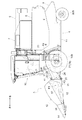
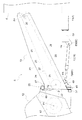
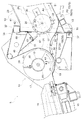
以下、本発明の一例である実施形態を図面に基づいて説明する。なお、説明において、図1及び図2に示す矢印Fの向きを「前」、図1及び図2に示す矢印Bの向きを「後」、図2に示す矢印Lの向きを「左」、図2に示す矢印Rの向きを「右」とする。 An embodiment, which is an example of the present invention, will be described below with reference to the drawings. In the description, the direction of arrow F shown in FIGS. 1 and 2 is “front”, the direction of arrow B shown in FIGS. 1 and 2 is “rear”, and the direction of arrow L shown in FIG. 2 is “left”. The direction of the arrow R shown in FIG. 2 is “right”.
図1、図2等に示すように、トウモロコシ収穫機(「収穫機」の一例)には、左右一対の前輪1及び左右一対の後輪2からなる走行装置3に支持されている自走可能な機体4、トウモロコシの房状体(「作物」の一例)を収穫して後方に向けて搬送する収穫搬送部5が備えられている。
As shown in FIGS. 1 and 2, the corn harvester (an example of a “harvester”) is capable of self-propelled movement supported by a traveling
図1、図2等に示すように、機体4には、収穫搬送部5から搬送されてくる包葉付きの房状体を脱穀処理(包葉の皮剥き及び穀粒の粒取り)する脱穀装置6、脱穀装置6で分離されたトウモロコシの穀粒を貯留可能な穀粒貯留部7、脱穀装置6で分離されたトウモロコシの包葉や芯部等の夾雑物を排出する排出部8、穀粒貯留部7に貯留された穀粒を外部に向けて排出可能なアンローダ9、搭乗者が運転操作を行う運転部10等が備えられている。機体4の下部には、枠状に組まれた車体フレーム11が備えられている。車体フレーム11は、走行装置3に支持されている。
As shown in FIG. 1, FIG. 2, etc., the
図1〜図8に示すように、収穫搬送部5には、機体4の前方に位置して機体4の左右幅に亘る収穫部12と、収穫部12の後部に連結され、機体4に上下揺動可能に支持された搬送部13と、が備えられている。
As shown in FIGS. 1 to 8, the harvesting and transporting
〔収穫部について〕
図1〜図8に示す収穫部12は、作物としてトウモロコシの房状体を収穫するように構成されている。図1、図2等に示すように、収穫部12には、左右方向に並べて配置されるデバイダ14が備えられている。収穫部12は、左右方向に4列の導入経路が設けられている。収穫部12には、導入経路毎に、左右一対の収穫ロール15、収穫ロール15の上部に位置する左右一対の無端搬送チェーン16が備えられている。
[About the harvest department]
The
図1、図2、図4〜図8に示すように、収穫部12には、収穫した房状体を横搬送して集めるオーガ17が備えられている。オーガ17には、第1回転軸18と、第1回転軸18と一体回転する筒部材19と、筒部材19の外周部に取り付けられ、房状体を押圧する左右一対の螺旋状の押圧体20と、が備えられている。
As shown in FIGS. 1, 2, and 4 to 8, the
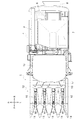
図4〜図8に示すように、収穫部12は、収穫した房状体を排出する開口21を後部に有している。収穫部12は、図6において矢印A1で示すように、オーガ17の下部側を房状体の搬送経路としている。オーガ17は、第1回転軸心P1周りに回動することにより、押圧体20で房状体を押圧して、房状体を後方に向けて搬送しながら、開口21に寄せ集める。オーガ17で集められた房状体は、開口21を通じて搬送部13側へ送られる。
As shown in FIGS. 4 to 8, the
〔搬送部について〕
図1〜図8に示す搬送部13は、収穫した房状体を後方に向けて搬送するように構成されている。図4〜図8に示すように、搬送部13は、前部に収穫部12の開口21に連結される入口22を有している。
[About transport section]
The carrying
図3〜図8等に示すように、搬送部13には、オーガ17から搬送されてくる房状体を受け入れる入口22が前面に設けられたケース23と、ケース23に収容され、ケース23の下部側を搬送経路とする無端回動式の搬送装置24と、が備えられている。搬送装置24は、図6において矢印A2で示すように、ケース23の下部側を房状体の搬送経路としている。
As shown in FIG. 3 to FIG. 8 and the like, the
図1、図5、図6、図8に示すように、搬送装置24には、従動輪体としての前側の回転体25と、駆動輪体としての後側の回転体26と、前側の回転体25と後側の回転体26とに亘って巻回される無端回動チェーン27と、無端回動チェーン27の周部に所定間隔を空けて設けられた搬送体28等が備えられている。
As shown in FIG. 1, FIG. 5, FIG. 6, and FIG. 8, the
図6に示すように、搬送装置24における前側の回転体25は、搬送部13の搬送方向に沿って位置変更可能である。図6に示す実線が回転体25を前側に位置調整した場合、図6に示す二点鎖線が回転体25を後側に位置調整した場合を示している。
As shown in FIG. 6, the
図6に示すように、ケース23の側面には、搬送部13の搬送方向に沿って長い複数の長孔29が設けられている。搬送部13には、前側の回転体25を左右方向に沿った第2回転軸心P2周りに回動自在に支持する第1取付部材30と、第1取付部材30に固定される第2取付部材31と、が備えられている。前側の回転体25の第2回転軸32は、第1取付部材30に設けられたボス部33に回動自在に支持されている。第1取付部材30は、ケース23の長孔29の所定箇所にボルト等からなる締結部材34を締結することで、ケース23に固定されている。
As shown in FIG. 6, the side surface of the
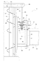
〔第1連結フレーム体について〕
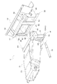
図3〜図8に示すように、収穫部12の後部には、左右方向において、開口21を含む範囲に設けられ、開口21よりも幅広の第1連結フレーム体35が備えられている。
[About the first connection frame body]
As shown in FIGS. 3 to 8, a rear part of the
図3、図4、図7等に示すように、第1連結フレーム体35には、収穫部12の後部に連結された左右の側壁36、左右の側壁36どうしを繋ぐ上下一対の左右方向に沿って延びる横フレーム37、上下の横フレーム37を繋ぐ左右一対の縦方向に沿って延びる縦フレーム38等が備えられている。左右の側壁36は、それぞれ、上部に折り返し部39を有している。
As shown in FIG. 3, FIG. 4, FIG. 7, etc., the left and
図6に示すように、第1連結フレーム体35の幅内には、開口21と入口22とを接続する逆U字型の案内部40が備えられている。案内部40は、左右の側壁36の間に配置されている。
As shown in FIG. 6, an inverted
〔第2連結フレーム体について〕
図3〜図8に示すように、搬送部13の前部には、第1連結フレーム体35に連結され、左右方向において、入口22を含む範囲に設けられ、かつ、入口22よりも幅広な第2連結フレーム体41が備えられている。
[About the second connection frame body]
As shown in FIGS. 3 to 8, a front portion of the
図3等に示すように、第2連結フレーム体41には、左右方向に沿って延びる載置フレーム42と、左右方向に沿って延びる支持フレーム43と、載置フレーム42と支持フレーム43とを繋ぐ左右一対の上下方向に沿って延びる第1後縦フレーム44と、第2後縦フレーム45と、載置フレーム42の前面に固定される左右一対の爪部49と、支持フレーム43の後部に固定される取付部材50と、が備えられている。
As shown in FIG. 3 and the like, the second
図4〜図8等に示すように、第1連結フレーム体35の上の横フレーム37を、第2連結フレーム体41において爪部49を乗り越えさせて載置フレーム42の上面に載置する。そして、第1連結フレーム体35の下の横フレーム37を、第2連結フレーム体41の取付部材50にボルト連結する。これにより、第1連結フレーム体35と第2連結フレーム体41とが連結され、収穫部12と搬送部13とが連結されるようになっている。
As shown in FIGS. 4 to 8, etc., the
図3〜図6、図8に示すように、搬送部13の前部の底部には、左右方向に沿って延びる支持フレーム43が備えられている。支持フレーム43は、搬送部13よりも側方に突出している。支持フレーム43には、搬送部13よりも側方に突出する突出部52が設けられている。機体4の前部には、車体フレーム11の一部として、左右方向に沿って延びる前フレーム53が備えられている。
As shown in FIGS. 3 to 6 and 8, a
〔下案内部材について〕
図3、図6等に示すように、収穫搬送部5には、収穫部12の底板部54の後端部とケース23の底板部51の前端部とを繋げる下案内部材55が備えられている。下案内部材55の前後方向中間部56は、側面視で湾曲状に上方に向けて突出している。下案内部材55には、収穫部12側の第1案内部材57と、ケース23側の第2案内部材58と、が備えられている。
[About the lower guide member]
As shown in FIGS. 3 and 6, the harvesting and conveying
図3、図6等に示すように、第1案内部材57は、逆U字状の案内部40の下端部に連結されている。第2案内部材58は、第2取付部材31に固定されている。第1案内部材57と逆U字状の案内部40とにより、前後に開口した筒状部材が構成されている。この筒状部材は、左右の側壁36の間に突っ込まれるようにして配置されている。
As shown in FIGS. 3 and 6, the
図6に示すように、第2案内部材58は、回転体25の位置変更に追従して位置変更されるように構成されている。具体的には、ケース23の長孔29における締結部材34の締結位置を変更することにより、ケース23に対する第1取付部材30、前側の回転体25、第2取付部材31、第2案内部材58の位置を、搬送部13の搬送方向に沿って調整できるようになっている。
As shown in FIG. 6, the
〔上案内部材について〕
図6に示すように、収穫搬送部5には、収穫部12と搬送部13の入口22との間において、下案内部材55の上方に、房状体を下方側に向けて案内する上案内部材60が備えられている。上案内部材60は、案内部40の上板体の下面に固定されている。上案内部材60は、案内部40内に連結支持されている。上案内部材60には、側面視で、略L字状に曲げられた板部材からなる剛性体61が備えられている。上案内部材60における案内面62の後端には、例えば樹脂製で弾性変形可能な板状体63が備えられている。板状体63は、剛性体61の下端部付近の箇所にボルト連結されている。
[About the upper guide member]
As shown in FIG. 6, in the harvesting and transporting
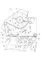
〔第1動力伝達装置、第2動力伝達装置、側部伝達装置について〕
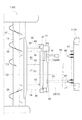
図7に示すように、案内部40と左右の側壁36のうち一方の側壁36との間の空間64には、搬送部13側の第1動力伝達装置65と、収穫部12側の第2動力伝達装置66とを連結する連結部67が通されている。図2、図7から理解されるように、第1動力伝達装置65、第2動力伝達装置66、連結部67は、機体4の右部側に配置されている。
[Regarding First Power Transmission Device, Second Power Transmission Device, Side Transmission Device]
As shown in FIG. 7, in the
エンジン(図示せず)から搬送部13側の第1動力伝達装置65に伝達された動力は、連結部67、第2動力伝達装置66に伝達され、その伝達された動力により、収穫部12側の装置であるオーガ17、収穫ロール15、及び、無端搬送チェーン16が駆動される。
The power transmitted from the engine (not shown) to the first
第2動力伝達装置66には、収穫部12の側部に設けられた側部伝達装置68と、一方の側壁36を貫通し、連結部67と側部伝達装置68とを繋ぐカウンタ軸69と、が備えられている。カウンタ軸69は、一方の側壁36と収穫部12の側壁部70とに支持されている。
The second
図7、図8に示すように、連結部67には、カウンタ軸69の端部に設けられたスプリング式のトルクリミッタ71が備えられている。連結部67には、チェーン式の無端回動体72と、無端回動体72にテンション力を付与する輪体73と、が備えられている。
As shown in FIGS. 7 and 8, the
また、連結部67には、輪体73に付勢力を付与するとともに付勢力を調整可能なスプリング74が、一方の側壁36に対して、空間64とは反対側の位置に設けられている。
輪体73は、左右方向に沿った枢支軸心P3周りに揺動可能な中継部材75の遊端部に回動可能に支持されている。中継部材75における枢支軸心P3と輪体73との間にスプリング74の一端部が引っ掛け支持されている。スプリング74の他端部は、調整ボルト機構76に連結されている。調整ボルト機構76の調整により、スプリング74のばね長が変更され、これにより、スプリング74から輪体73に付与される付勢力が調整される。
In addition, a
The
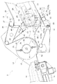
〔第1シリンダと第2シリンダについて〕
図1、図3〜図6、図8に示すように、機体4に対して収穫搬送部5を昇降させるために、昇降用の油圧式の第1シリンダ77と、昇降用の油圧式の第2シリンダ78と、が備えられている。第1シリンダ77及び第2シリンダ78を伸ばすと、収穫搬送部5が、昇降軸心P4周りに機体4に対して上昇し、一方、第1シリンダ77及び第2シリンダ78を縮めると、収穫搬送部5が、昇降軸心P4周りに機体4に対して下降する。
[Regarding the first cylinder and the second cylinder]
As shown in FIG. 1, FIG. 3 to FIG. 6, and FIG. 8, in order to move the harvesting and conveying
図4、図5等に示すように、第1シリンダ77と第2シリンダ78との両方は、支持フレーム43と機体4の前フレーム53とに亘って設けられている。
As shown in FIGS. 4 and 5, both the
第1シリンダ77は、搬送部13と機体4とに亘って設けられている。第1シリンダ77は、搬送部13の底部に連結されている。第1シリンダ77は、搬送部13の底部のうち第2シリンダ78が位置する側とは反対側の部分を支持している。具体的には、第1シリンダ77は、搬送部13の底部において支持フレーム43に連結されている。
The
第1シリンダ77の前端部は、一対の板部材からなる第1後ブラケット79を介して、左右方向を向く前横軸心P5周りに回動可能となる状態で、支持フレーム43に連結されている。第1シリンダ77の後端部は、前フレーム53に支持されている。説明を加えると、第1シリンダ77の後端部は、一対の板部材からなる第1前ブラケット80を介して、左右方向を向く後横軸心P6周りに回動可能となる状態で、前フレーム53に連結されている。
The front end portion of the
図4、図5等に示すように、第2シリンダ78は、収穫搬送部5と機体4とに亘って設けられている。説明を加えると、第2シリンダ78は、搬送部13と機体4とに亘って設けられている。第2シリンダ78は、支持フレーム43の突出部52に連結されている。
第2シリンダ78の前端部は、一対の板部材からなる第2後ブラケット81を介して、左右方向を向く前横軸心P5周りに回動可能となる状態で、支持フレーム43の突出部52に連結されている。
As shown in FIGS. 4 and 5, the
The front end portion of the
第2シリンダ78の後端部は、前フレーム53に支持されている。説明を加えると、第2シリンダ78の後端部は、一対の板部材からなる第2前ブラケット82を介して、左右方向を向く後横軸心P6周りに回動可能となる状態で、前フレーム53に支持されている。
The rear end of the
図4に示すように、機体4の左右中心C1に対して、搬送部13の左右中心C2は、左右一方側に偏倚している。このため、第1シリンダ77を、搬送部13の左右中心C2に対して左右一方側に偏倚した箇所に配置し、一方、第2シリンダ78を、機体4の左右中心C1よりも左右他方側に偏倚した箇所に配置してある。これにより、第1シリンダ77及び第2シリンダ78により、収穫搬送部5がバランス良く支持され、搬送部13に拗れが生じ難いものとなる。
As shown in FIG. 4, the left-right center C2 of the
〔別実施形態〕
以下、上記実施形態の一部を変更した別実施形態について説明する。各別実施形態は、説明している事項以外は、上記実施形態と同様である。各別実施形態は、矛盾が生じない限り、複数組み合わせることができる。尚、本発明の範囲は、説明している各実施形態に限定されるものではない。
[Another embodiment]
Hereinafter, another embodiment in which a part of the above embodiment is modified will be described. The respective other embodiments are the same as the above-mentioned embodiments except the matters described. A plurality of different embodiments can be combined as long as no contradiction occurs. It should be noted that the scope of the present invention is not limited to the described embodiments.
(1)上記実施形態では、第2シリンダ78は、搬送部13と機体4とに亘って設けられているものを例示しているが、これに限られない。例えば、第2シリンダ78が、収穫部12と機体4とに亘って設けられていてもよい。
(1) In the above embodiment, the
(2)上記別実施形態では、搬送部13の底部に、左右方向に沿って延びる支持フレーム43が備えられ、第1シリンダ77と第2シリンダ78との両方が、支持フレーム43と機体4とに亘って設けられているものを例示しているが、これに限られない。第1シリンダ77と第2シリンダ78とのうち少なくともいずれか一方が、支持フレーム43以外の部材に取り付けられていてもよい。
(2) In the above-described other embodiment, the
(3)上記実施形態では、支持フレーム43は、搬送部13よりも側方に突出しており、第1シリンダ77は、搬送部13の底部において支持フレーム43に連結され、第2シリンダ78が支持フレーム43の突出部52に連結されているものを例示しているが、これに限られない。例えば、第1シリンダ77が、支持フレーム43以外の部材に連結されていてもよい。また、例えば、第2シリンダ78が支持フレーム43における突出部52以外の箇所に連結されていてもよい。また、例えば、第1シリンダ77及び第2シリンダ78の両方が搬送部13の底部に支持されていてもよい。また、支持フレーム43に、突出部52とは反対側に突出する他の突出部を設け、第1シリンダ77をその他の突出部に連結したものであってもよい。
(3) In the above-described embodiment, the
(4)上記実施形態では、第1シリンダ77が、搬送部13の底部のうち第2シリンダ78が位置する側とは反対側の部分を支持しているものを例示しているが、これに限られない。例えば、第1シリンダ77が搬送部13の底部のうち第2シリンダ78が位置する側と同じ側の部分が支持しているものであってもよい。
(4) In the above-described embodiment, the
(5)上記実施形態では、機体4の前部に、左右方向に沿って延びる前フレーム53が備えられ、第1シリンダ77の後端部および第2シリンダ78の後端部は、前フレーム53に支持されているものを例示しているが、これに限られない。例えば、第1シリンダ77の後端部および第2シリンダ78の後端部のうち少なくとも一方が、前フレーム53以外の部材に支持されていてもよい。
(5) In the above-described embodiment, the front portion of the
(6)上記実施形態では、下案内部材55の前後方向中間部56が、側面視で湾曲状に上方に向けて突出しているものを例示しているが、これに限られない。例えば、前後方向中間部が、側面視で逆向きのL字型となるように角状に上方に向けて突出している下案内部材であってもよい。また、例えば、前後方向中間部が、側面視で真っ直ぐに斜め後ろ下がり傾斜となっている下案内部材であってもよい。
(6) In the above-described embodiment, the
(7)上記実施形態では、下案内部材55に、収穫部12側の第1案内部材57と、ケース23側の第2案内部材58と、が備えられているものを例示しているが、これに限られない。例えば、下案内部材55が単一の部材で構成されていてもよい。
(7) In the above embodiment, the
(8)上記実施形態では、搬送装置24における前側の回転体25が、搬送部13の搬送方向に沿って位置変更可能であり、第2案内部材58が、回転体25の位置変更に追従して位置変更されるように構成されているものを例示しているが、これに限られない。例えば、図9に示すように、下案内部材55のうち第2案内部材158が、位置変更不能にケース23に支持されていてもよい。この場合、第2案内部材158は、前側の回転体25とは別個に支持されるものとなっている。また、この場合、図9に示すように、搬送装置24における前側の回転体25は、搬送部13の搬送方向に沿って位置変更不能になっていてもよい。
(8) In the above embodiment, the position of the front
(9)上記実施形態では、上案内部材60における案内面62の後端に、弾性変形可能な板状体63が備えられているものを例示しているがこれに限られない。例えば、このような弾性変形可能な板状体63が備えられていなくてもよい。
(9) In the above embodiments, the
(10)上記実施形態では、収穫部12と入口22との間において、下案内部材55の上方に、房状体を下方側に向けて案内する上案内部材60が備えられているものを例示しているがこれに限られない。例えば、このような上案内部材60が備えられていなくてもよい。
(10) In the above embodiment, an example in which the
(11)上記実施形態では、収穫部12の底板部54の後端部とケース23の底板部51の前端部とを繋げる下案内部材55が備えられているものを例示しているがこれに限られない。例えば、このような下案内部材55が備えられていなくてもよい。
(11) In the above embodiment, the
(12)上記実施形態では、第1連結フレーム体35の幅内に、開口21と入口22とを接続する案内部40が備えられているものを例示しているが、これに限られない。例えば、このような案内部40が備えられていなくてもよい。
(12) In the above embodiment, the
(13)上記実施形態では、第1連結フレーム体35に、収穫部12の後部に連結された左右の側壁36と、左右の側壁36どうしを繋ぐ横フレーム37と、が備えられているものを例示しているが、これに限られない。例えば、このような側壁36や横フレーム37が備えられていなくてもよい。
(13) In the above embodiment, the first
(14)上記実施形態では、案内部40と左右の側壁36のうち一方の側壁36との間の空間64に、搬送部13側の第1動力伝達装置65と、収穫部12側の第2動力伝達装置66とを連結する連結部67が通されているものを例示しているが、これに限られない。
例えば、このような連結部67が、空間64以外の箇所に通されていてもよい。
(14) In the above embodiment, in the
For example, such a connecting
(15)上記実施形態では、第2動力伝達装置66に、収穫部12の側部に設けられた側部伝達装置68と、一方の側壁36を貫通し、連結部67と側部伝達装置68とを繋ぐカウンタ軸69と、が備えられ、カウンタ軸69は、一方の側壁36と収穫部12の側壁部70とに支持されているものを例示しているが、これに限られない。例えば、例えば、一方の側壁36を貫通しない態様のカウンタ軸69が備えられていてもよい。
(15) In the above-described embodiment, the second
(16)上記実施形態では、連結部67に、カウンタ軸69の端部に設けられたスプリング式のトルクリミッタ71が備えられているものを例示しているがこれに限られない。例えば、このようなトルクリミッタ71がカウンタ軸69に備えられていなくてもよい。
(16) In the above embodiment, the
(17)上記実施形態では、連結部67に、無端回動体72と、無端回動体72にテンション力を付与する輪体73と、が備えられ、輪体73に付勢力を付与するとともに付勢力を調整可能なスプリング74が、一方の側壁36に対して、空間64とは反対側の位置に設けられているものを例示しているが、これに限られない。例えば、このようなスプリング74が、空間64に設けられていたり、全く別の箇所に設けられていたりしてもよい。
(17) In the above-described embodiment, the connecting
(18)上記実施形態では、第1動力伝達装置65、第2動力伝達装置66、連結部67が、機体4の右部側に配置されているものが例示されているが、これに限られない。例えば、第1動力伝達装置65、第2動力伝達装置66、連結部67が、機体4の左部側に配置されていてもよい。
(18) In the above embodiment, the first
(19)上記実施形態では、収穫部12の後部に、左右方向において、開口21を含む範囲に設けられ、かつ、開口21よりも幅広の第1連結フレーム体35が備えられ、搬送部13の前部に、第1連結フレーム体35に連結され、左右方向において、入口22を含む範囲に設けられ、入口22よりも幅広で、第2連結フレーム体41が備えられているものを例示しているが、これに限られない。例えば、このような第1連結フレーム体35や第2連結フレーム体41が備えられていなくてもよい。
(19) In the above-described embodiment, the rear part of the
本発明は、上記トウモロコシ収穫機以外にも、イネ、大豆、そば等の作物を収穫する種々の収穫機に利用できる。 INDUSTRIAL APPLICABILITY The present invention can be applied to various harvesters for harvesting crops such as rice, soybeans and buckwheat, in addition to the above corn harvesters.
4 :機体
5 :収穫搬送部
12 :収穫部
13 :搬送部
17 :オーガ
21 :開口
22 :入口
23 :ケース
24 :搬送装置
25 :前側の回転体
35 :第1連結フレーム体
36 :側壁
37 :横フレーム
40 :案内部
41 :第2連結フレーム体
43 :支持フレーム
51 :底板部
52 :突出部
53 :前フレーム
54 :底板部
55 :下案内部材
56 :前後方向中間部
57 :第1案内部材
58,158:第2案内部材
60 :上案内部材
62 :案内面
63 :板状体
64 :空間
65 :第1動力伝達装置
66 :第2動力伝達装置
67 :連結部
68 :側部伝達装置
69 :カウンタ軸
70 :側壁部
71 :トルクリミッタ
72 :無端回動体
73 :輪体
74 :スプリング
77 :第1シリンダ
78 :第2シリンダ
4: Machine body 5: Harvesting and conveying section 12: Harvesting section 13: Conveying section 17: Auger 21: Opening 22: Entrance 23: Case 24: Conveying device 25: Front rotating body 35: First connecting frame body 36: Side wall 37: Horizontal frame 40: Guide portion 41: Second connecting frame body 43: Support frame 51: Bottom plate portion 52: Projection portion 53: Front frame 54: Bottom plate portion 55: Lower guide member 56: Front-rear direction intermediate portion 57: First guide
Claims (17)
前記収穫搬送部に、機体の前方に位置して前記機体の左右幅に亘る収穫部と、前記収穫部の後部に連結され、前記機体に上下揺動可能に支持された搬送部と、が備えられ、
前記収穫部は、左右方向において前記搬送部よりも幅広に構成され、且つ、前記搬送部に対して左右方向一方側に偏倚した状態で連結され、
前記搬送部と前記機体とに亘って設けられた昇降用の第1シリンダと、
前記搬送部と前記機体とに亘って設けられた昇降用の第2シリンダと、が備えられ、
前記搬送部の底部に、左右方向に沿って延びる支持フレームが備えられ、
前記支持フレームに、前記搬送部の側方から前記左右方向一方側に向けて突出する突出部が備えられ、
前記第1シリンダと前記第2シリンダとの両方が、前記支持フレームと前記機体とに亘って設けられ、
前記第1シリンダは、前記搬送部の底部において前記支持フレームに連結され、
前記第2シリンダは、前記突出部に連結されている収穫機。 A harvesting and transporting unit that harvests crops and transports them backward is provided.
The harvesting and transporting unit includes a harvesting unit that is located in front of the machine body and extends over the left and right width of the machine body, and a transporting unit that is connected to a rear portion of the harvesting unit and is supported by the machine body so as to be vertically swingable. The
The harvesting section is configured to be wider than the transporting section in the left-right direction, and is connected to the transporting section in a state of being biased to one side in the left-right direction,
A first cylinder for raising and lowering provided across the transport section and the machine body,
A second cylinder for raising and lowering provided across the transport section and the machine body ,
A support frame extending in the left-right direction is provided at the bottom of the transport unit,
The support frame is provided with a protrusion that protrudes from the side of the transport unit toward the one side in the left-right direction,
Both the first cylinder and the second cylinder are provided across the support frame and the machine body,
The first cylinder is connected to the support frame at the bottom of the transport unit,
The harvester , wherein the second cylinder is connected to the protrusion .
前記収穫搬送部に、機体の前方に位置して前記機体の左右幅に亘る収穫部と、前記収穫部の後部に連結され、前記機体に上下揺動可能に支持された搬送部と、が備えられ、
前記収穫部は、左右方向において前記搬送部よりも幅広に構成され、且つ、前記搬送部に対して左右方向一方側に偏倚した状態で連結され、
前記搬送部と前記機体とに亘って設けられた昇降用の第1シリンダと、
前記搬送部と前記機体とに亘って設けられた昇降用の第2シリンダと、が備えられ、
前記搬送部の側方から前記左右方向一方側に向けて突出する突出部が備えられ、
前記第1シリンダは、前記搬送部の底部に連結され、
前記第2シリンダは、前記突出部に連結されている収穫機。 A harvesting and transporting unit that harvests crops and transports them backward is provided.
The harvesting and transporting unit includes a harvesting unit that is located in front of the machine body and extends over the left and right width of the machine body, and a transporting unit that is connected to a rear portion of the harvesting unit and is supported by the machine body so as to be vertically swingable. The
The harvesting section is configured to be wider than the transporting section in the left-right direction, and is connected to the transporting section in a state of being biased to one side in the left-right direction,
A first cylinder for raising and lowering provided across the transport section and the machine body,
A second cylinder for raising and lowering provided across the transport section and the machine body ,
A projecting portion projecting from the lateral side of the transport section toward the one side in the left-right direction is provided,
The first cylinder is connected to the bottom of the transfer unit,
The harvester , wherein the second cylinder is connected to the protrusion .
前記第1シリンダの後端部および前記第2シリンダの後端部は、前記前フレームに支持されている請求項1から3のいずれか一項に記載の収穫機。 The front part of the aircraft is provided with a front frame extending in the left-right direction,
The harvester according to any one of claims 1 to 3 , wherein a rear end portion of the first cylinder and a rear end portion of the second cylinder are supported by the front frame.
前記搬送部が、収穫した前記房状体を後方に向けて搬送するように構成され、
前記収穫部に、収穫した前記房状体を横搬送して集めるオーガが備えられ、
前記搬送部に、前記オーガから搬送されてくる前記房状体を受け入れる入口が前面に設けられたケースと、前記ケースに収容され、前記ケースの下部側を搬送経路とする無端回動式の搬送装置と、が備えられ、
前記収穫部の底板部の後端部と前記ケースの底板部の前端部とを繋げる下案内部材が備えられている請求項1から4のいずれか一項に記載の収穫機。 The harvesting unit is configured to harvest a tuft of corn as the crop,
The transport unit is configured to transport the harvested tufts rearward,
The harvesting section is provided with an auger for laterally collecting and collecting the harvested tufts,
A case in which an entrance for receiving the tufted body conveyed from the auger is provided in the front surface of the conveyance unit, and an endless rotation type conveyance that is housed in the case and has a lower side of the case as a conveyance path. And a device,
Harvesting machine according to any one of 4 claims 1 where the lower guide member is provided to connect the front end of the bottom plate portion of the case and the rear end portion of the bottom plate portion of the harvesting unit.
前記第2案内部材が、前記回転体の位置変更に追従して位置変更されるように構成されている請求項7に記載の収穫機。 The rotating body on the front side of the carrying device is positionally changeable along the carrying direction of the carrying section,
The harvester according to claim 7 , wherein the second guide member is configured to be changed in position in accordance with a change in the position of the rotating body.
収穫機。 The upper guide member for guiding the tuft toward the lower side is provided above the lower guide member between the harvesting section and the inlet, according to any one of claims 5 to 8. Harvester as described.
前記収穫搬送部に、機体の前方に位置して前記機体の左右幅に亘る収穫部と、前記収穫部の後部に連結され、前記機体に上下揺動可能に支持された搬送部と、が備えられ、
前記収穫部が、収穫した前記作物を排出する開口を後部に有し、
前記搬送部が、前部に前記開口と連結される入口を有し、収穫した前記作物を後方に向けて搬送するように構成され、
前記収穫部の後部に、左右方向において、前記開口を含む範囲に設けられ、かつ、前記開口よりも幅広な第1連結フレーム体が備えられ、
前記搬送部の前部に、前記第1連結フレーム体に連結され、左右方向において、前記入口を含む範囲に設けられ、かつ、前記入口よりも幅広な第2連結フレーム体が備えられている収穫機。 A harvesting and transporting unit that harvests crops and transports them backward is provided.
The harvesting and transporting unit includes a harvesting unit that is located in front of the machine body and extends over the left and right width of the machine body, and a transporting unit that is connected to a rear portion of the harvesting unit and is supported by the machine body so as to be vertically swingable. The
The harvesting section has an opening at the rear for discharging the harvested crop,
The transport unit has an inlet connected to the opening at the front, and is configured to transport the harvested crop backward.
In the rear part of the harvesting part, a first connecting frame body that is provided in a range including the opening in the left-right direction and is wider than the opening is provided.
The front of the transport unit, coupled to said first connecting frame member, in the horizontal direction, the provided range including an inlet and yield that are equipped with wide second connection frame body than said inlet Harvesting machine.
前記カウンタ軸は、前記一方の側壁と前記収穫部の側壁とに支持されている請求項14に記載の収穫機。 The second power transmission device includes a side transmission device provided on a side portion of the harvesting unit, and a counter shaft that penetrates the one side wall and connects the connecting portion and the side transmission device. The
The harvester according to claim 14 , wherein the counter shaft is supported by the one sidewall and the sidewall of the harvesting unit.
前記輪体に付勢力を付与するとともに前記付勢力を調整可能なスプリングが、前記一方の側壁に対して、前記空間とは反対側の位置に設けられている請求項14から16のいずれか一項に記載の収穫機。 The connecting portion includes an endless rotating body, and a ring body that applies a tension force to the endless rotating body,
Adjustable spring the biasing force while applying a biasing force to the wheel body, wherein to one of the side walls, one of claims 14 to 16 provided in the position opposite to the space one Harvester according to item.
Priority Applications (2)
| Application Number | Priority Date | Filing Date | Title |
|---|---|---|---|
| JP2016208992A JP6715744B2 (en) | 2016-10-25 | 2016-10-25 | Harvester |
| CN201711000417.8A CN107969222B (en) | 2016-10-25 | 2017-10-24 | Harvester |
Applications Claiming Priority (1)
| Application Number | Priority Date | Filing Date | Title |
|---|---|---|---|
| JP2016208992A JP6715744B2 (en) | 2016-10-25 | 2016-10-25 | Harvester |
Publications (2)
| Publication Number | Publication Date |
|---|---|
| JP2018068146A JP2018068146A (en) | 2018-05-10 |
| JP6715744B2 true JP6715744B2 (en) | 2020-07-01 |
Family
ID=62012585
Family Applications (1)
| Application Number | Title | Priority Date | Filing Date |
|---|---|---|---|
| JP2016208992A Active JP6715744B2 (en) | 2016-10-25 | 2016-10-25 | Harvester |
Country Status (2)
| Country | Link |
|---|---|
| JP (1) | JP6715744B2 (en) |
| CN (1) | CN107969222B (en) |
Families Citing this family (4)
| Publication number | Priority date | Publication date | Assignee | Title |
|---|---|---|---|---|
| WO2020012513A1 (en) * | 2018-07-10 | 2020-01-16 | Moro Aratri S.R.L. | Digging plough |
| JP7169944B2 (en) * | 2019-06-27 | 2022-11-11 | 株式会社クボタ | Pre-harvest treatment equipment for corn harvester |
| JP7433145B2 (en) * | 2020-06-23 | 2024-02-19 | 株式会社クボタ | harvester |
| JP7774514B2 (en) * | 2022-07-14 | 2025-11-21 | 株式会社クボタ | Harvesting conveyor and corn harvester |
Family Cites Families (9)
| Publication number | Priority date | Publication date | Assignee | Title |
|---|---|---|---|---|
| JPS6174332U (en) * | 1984-10-22 | 1986-05-20 | ||
| JPH083236Y2 (en) * | 1989-12-06 | 1996-01-31 | ヤンマー農機株式会社 | Combine harvester |
| JPH06153662A (en) * | 1993-07-28 | 1994-06-03 | Iseki & Co Ltd | Combine harvester culm carrier |
| JP2001218520A (en) * | 2000-02-09 | 2001-08-14 | Seirei Ind Co Ltd | Transmission for lodged rice plant-raising machine in combine harvester |
| CN107258218B (en) * | 2011-12-16 | 2018-10-12 | 株式会社久保田 | The harvesting pretreatment unit of harvester |
| US8826635B2 (en) * | 2013-02-06 | 2014-09-09 | Deere & Company | Combine harvester with feederhouse arrangement |
| JP2014193116A (en) * | 2013-03-28 | 2014-10-09 | Kubota Corp | Ordinal type combine |
| JP2014233225A (en) * | 2013-05-31 | 2014-12-15 | 株式会社クボタ | Harvesting machine |
| JP6275004B2 (en) * | 2014-09-02 | 2018-02-07 | 株式会社クボタ | Harvesting machine |
-
2016
- 2016-10-25 JP JP2016208992A patent/JP6715744B2/en active Active
-
2017
- 2017-10-24 CN CN201711000417.8A patent/CN107969222B/en active Active
Also Published As
| Publication number | Publication date |
|---|---|
| CN107969222A (en) | 2018-05-01 |
| CN107969222B (en) | 2022-09-20 |
| JP2018068146A (en) | 2018-05-10 |
Similar Documents
| Publication | Publication Date | Title |
|---|---|---|
| JP6715744B2 (en) | Harvester | |
| EP3590321B1 (en) | System for adjusting the conveyor belt tension force within an agricultural harvester | |
| CN110226415B (en) | Combine harvester and threshing device mounted on the combine harvester | |
| JP6566909B2 (en) | Working machine | |
| JP6556203B2 (en) | Harvester | |
| JP6765348B2 (en) | combine | |
| JP2013135619A (en) | Combine harvester | |
| CN106572636B (en) | Harvester | |
| CN113677189B (en) | Harvester | |
| JP2012029568A (en) | Reaping and transporting part of combine harvester | |
| JP2013220054A (en) | Harvester | |
| JP7797325B2 (en) | Work equipment | |
| JP6650711B2 (en) | Harvester | |
| JP7368345B2 (en) | combine | |
| JP5984631B2 (en) | Combine | |
| JP2014068586A (en) | Combine-harvester | |
| JP3956580B2 (en) | Combine | |
| JP7266487B2 (en) | harvester | |
| JP7094198B2 (en) | Harvester | |
| JP6999509B2 (en) | combine | |
| CN2857439Y (en) | United reaper | |
| JP4565571B2 (en) | Combine | |
| JP6373131B2 (en) | Harvesting machine | |
| JP3743722B2 (en) | Combine harvester | |
| JP2006254706A (en) | Reaping apparatus of combine harvester |
Legal Events
| Date | Code | Title | Description |
|---|---|---|---|
| A621 | Written request for application examination |
Free format text: JAPANESE INTERMEDIATE CODE: A621 Effective date: 20181226 |
|
| A977 | Report on retrieval |
Free format text: JAPANESE INTERMEDIATE CODE: A971007 Effective date: 20190821 |
|
| A131 | Notification of reasons for refusal |
Free format text: JAPANESE INTERMEDIATE CODE: A131 Effective date: 20191008 |
|
| A521 | Request for written amendment filed |
Free format text: JAPANESE INTERMEDIATE CODE: A523 Effective date: 20191206 |
|
| TRDD | Decision of grant or rejection written | ||
| A01 | Written decision to grant a patent or to grant a registration (utility model) |
Free format text: JAPANESE INTERMEDIATE CODE: A01 Effective date: 20200512 |
|
| A61 | First payment of annual fees (during grant procedure) |
Free format text: JAPANESE INTERMEDIATE CODE: A61 Effective date: 20200609 |
|
| R150 | Certificate of patent or registration of utility model |
Ref document number: 6715744 Country of ref document: JP Free format text: JAPANESE INTERMEDIATE CODE: R150 |