JP6714974B2 - Current detector - Google Patents
Current detector Download PDFInfo
- Publication number
- JP6714974B2 JP6714974B2 JP2015101880A JP2015101880A JP6714974B2 JP 6714974 B2 JP6714974 B2 JP 6714974B2 JP 2015101880 A JP2015101880 A JP 2015101880A JP 2015101880 A JP2015101880 A JP 2015101880A JP 6714974 B2 JP6714974 B2 JP 6714974B2
- Authority
- JP
- Japan
- Prior art keywords
- wiring
- fixed
- members
- wiring members
- nut
- Prior art date
- Legal status (The legal status is an assumption and is not a legal conclusion. Google has not performed a legal analysis and makes no representation as to the accuracy of the status listed.)
- Active
Links
Images


Classifications
-
- G—PHYSICS
- G01—MEASURING; TESTING
- G01R—MEASURING ELECTRIC VARIABLES; MEASURING MAGNETIC VARIABLES
- G01R15/00—Details of measuring arrangements of the types provided for in groups G01R17/00 - G01R29/00, G01R33/00 - G01R33/26 or G01R35/00
-
- G—PHYSICS
- G01—MEASURING; TESTING
- G01R—MEASURING ELECTRIC VARIABLES; MEASURING MAGNETIC VARIABLES
- G01R15/00—Details of measuring arrangements of the types provided for in groups G01R17/00 - G01R29/00, G01R33/00 - G01R33/26 or G01R35/00
- G01R15/14—Adaptations providing voltage or current isolation, e.g. for high-voltage or high-current networks
- G01R15/146—Measuring arrangements for current not covered by other subgroups of G01R15/14, e.g. using current dividers, shunts, or measuring a voltage drop
-
- G—PHYSICS
- G01—MEASURING; TESTING
- G01R—MEASURING ELECTRIC VARIABLES; MEASURING MAGNETIC VARIABLES
- G01R1/00—Details of instruments or arrangements of the types included in groups G01R5/00 - G01R13/00 and G01R31/00
- G01R1/20—Modifications of basic electric elements for use in electric measuring instruments; Structural combinations of such elements with such instruments
- G01R1/203—Resistors used for electric measuring, e.g. decade resistors standards, resistors for comparators, series resistors, shunts
-
- G—PHYSICS
- G01—MEASURING; TESTING
- G01R—MEASURING ELECTRIC VARIABLES; MEASURING MAGNETIC VARIABLES
- G01R19/00—Arrangements for measuring currents or voltages or for indicating presence or sign thereof
- G01R19/0092—Arrangements for measuring currents or voltages or for indicating presence or sign thereof measuring current only
-
- G—PHYSICS
- G01—MEASURING; TESTING
- G01R—MEASURING ELECTRIC VARIABLES; MEASURING MAGNETIC VARIABLES
- G01R19/00—Arrangements for measuring currents or voltages or for indicating presence or sign thereof
- G01R19/32—Compensating for temperature change
-
- H—ELECTRICITY
- H01—ELECTRIC ELEMENTS
- H01C—RESISTORS
- H01C1/00—Details
- H01C1/14—Terminals or tapping points or electrodes specially adapted for resistors; Arrangements of terminals or tapping points or electrodes on resistors
- H01C1/148—Terminals or tapping points or electrodes specially adapted for resistors; Arrangements of terminals or tapping points or electrodes on resistors the terminals embracing or surrounding the resistive element
-
- H—ELECTRICITY
- H01—ELECTRIC ELEMENTS
- H01C—RESISTORS
- H01C13/00—Resistors not provided for elsewhere
-
- H—ELECTRICITY
- H01—ELECTRIC ELEMENTS
- H01C—RESISTORS
- H01C13/00—Resistors not provided for elsewhere
- H01C13/02—Structural combinations of resistors
-
- H—ELECTRICITY
- H01—ELECTRIC ELEMENTS
- H01C—RESISTORS
- H01C7/00—Non-adjustable resistors formed as one or more layers or coatings; Non-adjustable resistors made from powdered conducting material or powdered semi-conducting material with or without insulating material
- H01C7/06—Non-adjustable resistors formed as one or more layers or coatings; Non-adjustable resistors made from powdered conducting material or powdered semi-conducting material with or without insulating material including means to minimise changes in resistance with changes in temperature
Description
本発明は、電流配線として用いながら精度の高い電流測定が可能な電流検出装置に関する。 The present invention relates to a current detection device capable of highly accurate current measurement while being used as a current wiring.
バッテリの充放電電流の検出、電気自動車やハイブリッド自動車等を駆動するモータ電流の検出、エアコン等の電気機器や太陽電池等による発電設備等の電流の検出等において、シャント抵抗器を用いて、抵抗体への通電によって生じる電位差を計測することにより、電流が検出されている。 Use a shunt resistor to detect the charging/discharging current of a battery, the current of a motor that drives an electric vehicle or hybrid vehicle, the electric current of an electric device such as an air conditioner, or the current of a power generation facility such as a solar cell. The current is detected by measuring the potential difference caused by the energization of the body.
従来、シャント抵抗器とバスバーを接続する方法として、シャント抵抗器の電極部とバスバーに孔を形成しておき、この孔を介してボルトとナットで固定する方法が知られている。また、シャント抵抗器の電極部をボルト状に形成し、この電極部にナットを用いてバスバーを固定する方法が知られている(特許文献1参照)。 Conventionally, as a method of connecting a shunt resistor and a bus bar, a method is known in which holes are formed in the electrode portion of the shunt resistor and the bus bar and the bolts and nuts are fixed through the holes. Further, a method is known in which an electrode portion of a shunt resistor is formed in a bolt shape and a nut is used for the electrode portion to fix the bus bar (see Patent Document 1).
しかしながら、このようなバスバーとシャント抵抗器の接続方法では、接続部分が増えることになるため、接触抵抗による発熱の要因となり、また、接続信頼性の確保において問題がある。そこで、大電流を検出する用途に高い信頼性で使用できる電流検出装置が望まれていて、特許文献2には、長尺の第1端子および第2端子と、それら各端子の間に溶接固定されたシャント抵抗から構成されるバスバーが開示されている(図6など参照)。 However, in such a method of connecting the bus bar and the shunt resistor, the number of connecting portions is increased, which causes heat generation due to contact resistance, and there is a problem in ensuring connection reliability. Therefore, there is a demand for a current detection device that can be used with high reliability for the purpose of detecting a large current, and in Patent Document 2, a long first terminal and a second terminal are fixed by welding between these terminals. A bus bar composed of the shunt resistor is disclosed (see FIG. 6, etc.).
しかしながら、シャント抵抗として構成されたバスバーは、他のバスバー等にボルトとナット等で接続固定される。その際、ボルトまたはナットが自由に動き、固定作業が煩雑になることがある。例えば、自動車のエンジンルーム等の狭い空間等において、ボルトまたはナットの一方を固定しつつ、他方を回転締着することは必ずしも容易でない。 However, the bus bar configured as a shunt resistor is connected and fixed to another bus bar or the like with bolts and nuts or the like. At that time, the bolts or nuts may move freely, and the fixing work may be complicated. For example, in a narrow space such as an engine room of an automobile, it is not always easy to fix one of the bolt and the nut while rotating the other.
本発明は、上述の事情に基づいてなされたもので、シャント抵抗として構成されたバスバーに、他の部材をネジ止め部材の回転締着により容易に接続固定できる電流検出装置を提供することを目的とする。 The present invention has been made based on the above circumstances, and an object of the present invention is to provide a current detection device capable of easily connecting and fixing another member to a bus bar configured as a shunt resistor by rotationally fastening a screwing member. And
本発明の電流検出装置は、導電性の金属材からなる一対の配線部材と、これらの配線部材よりも抵抗温度係数の小さい金属材であって、配線部材と接合された抵抗体と、少なくともいずれかの配線部材に固定された、該配線部材とは別部材のネジ止め部材と、を備え、ネジ止め部材は、平坦部分と雌ネジ部と突出部を備えたナットであり、配線部材に孔部を備え、突出部を孔部内に浅く圧入することにより、ネジ止め部材の平坦部分は、孔部の周囲の配線部材の表面に当接しており、且つ、ネジ止め部材の突出部は、孔部の内周面に当接していて、一対の配線部材は、いずれか一方または双方に屈曲部を備え、配線部材の一面に前記ネジ止め部材が固定され、配線部材の他面にバスバーを配置し、これを挟んで他のネジ止め部材が前記ネジ止め部材に回転締着され、配線部材の抵抗体との接合面と、前記ネジ止め部材の固着部との中間に静止体への固定部を設けた、ことを特徴とする。 The current detecting device of the present invention includes at least one of a pair of wiring members made of a conductive metal material, a metal material having a resistance temperature coefficient smaller than those of the wiring members, and a resistor joined to the wiring member. And a screw-fastening member that is a member different from the wiring member, the screw-fastening member being a nut having a flat portion, a female screw portion, and a protruding portion. The flat portion of the screw fastening member is in contact with the surface of the wiring member around the hole portion by press-fitting the projection portion shallowly into the hole portion, and the projection portion of the screw fastening member is The pair of wiring members are in contact with the inner peripheral surface of the portion, and one or both of them has a bent portion, the screw member is fixed to one surface of the wiring member, and the bus bar is arranged on the other surface of the wiring member. Then, another screw-fastening member is rotationally fastened to the screw-fastening member with the screw-fastening member sandwiched therebetween, and a fixing portion to the stationary body is provided between the joining surface of the wiring member and the resistor and the fixing portion of the screw-fastening member. Is provided .
すなわち、バスバー状のシャント式電流検出装置であって、配線部材に、該配線部材とは別部材のネジ止め部材(ボルトまたはナット)の一方が固定された構造である。従って、配線部材の一面に一方のネジ止め部材を固定し、該配線部材の他面に配置した他の部材を挟み、他方のネジ止め部材を上記一方のネジ止め部材に回転締着する。これにより、一方のネジ止め部材の固定作業が不要となり、他方のネジ止め部材の回転締着作業のみで、配線部材の他面への他の部材の固定作業が容易に行える。特に、他方のネジ止め部材側のみからしか回転締着作業が行えない場合に有用である。 That is, the shunt-type current detection device is in the form of a bus bar, and has a structure in which one of the screw fastening members (bolts or nuts) that is a member different from the wiring member is fixed to the wiring member. Therefore, one screwing member is fixed to one surface of the wiring member, the other member arranged on the other surface of the wiring member is sandwiched, and the other screwing member is rotationally fastened to the one screwing member. This eliminates the need for fixing one screwing member, and facilitates fixing the other member to the other surface of the wiring member only by rotating and fastening the other screwing member. In particular, it is useful when the rotation fastening operation can be performed only from the other screw fastening member side.
そして、ネジ止め部材が配線部材とは別部材なので、強度を有するネジ止め部材を選択できる。また、配線部材自体の加工が最低限で済む。また、バスバーの配線機能と、シャント式の電流検出機能を一体化したバスバー状の電流検出装置であるため、部品点数を少なくでき、接点数が少なく、高精度の電流検出が可能となる。 Since the screwing member is a member different from the wiring member, a screwing member having strength can be selected. Further, the processing of the wiring member itself is minimal. In addition, since the busbar-shaped current detection device integrates the wiring function of the busbar and the shunt-type current detection function, the number of components can be reduced, the number of contacts can be reduced, and highly accurate current detection can be performed.
以下、本発明の実施形態について、図1乃至図10を参照して説明する。なお、各図中、同一または相当する部材または要素には、同一の符号を付して説明する。 Embodiments of the present invention will be described below with reference to FIGS. 1 to 10. In the drawings, the same or corresponding members or elements will be designated by the same reference numerals.
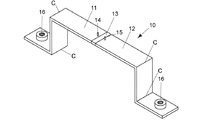
図1は本発明の実施例1の電流検出装置10を示す。この装置は、Cu、Cu系合金、Al等の高導電性の金属材からなる長尺の第1配線部材11および第2配線部材12と、これらの配線部材よりも抵抗温度係数の小さい金属材であって、第1配線部材および第2配線部材と接合された抵抗体13とを備える。長尺の第1配線部材11および第2配線部材12は電流経路となるバスバーであり、抵抗体13に接合する端子材でもある。第1配線部材11と第2配線部材12は、長さや形状が同一でもよく、また、異なっていてもよい。
1 shows a
抵抗体13はCu−Mn系、Cu−Ni系、Ni−Cr系等の抵抗温度係数がCu等の金属材よりも格段に小さい抵抗合金材からなる金属材で構成されている。そして、抵抗体13の両端面は配線部材11の端面と配線部材12の端面に、端面同士を突き合わせて溶接され、接合面が形成されている。溶接には、電子ビーム溶接、レーザービーム溶接、ろう接、等が用いられる。なお、抵抗体の端部と配線部材の端部を重ねて、圧接する等の構造でもよい。従って、この電流検出装置10は全体としてバスバー状である。
The
抵抗体13の両側の配線部材11,12には、抵抗体13の近傍に電圧検出端子14,15が設けられている。配線部材11,12に流れる電流は、抵抗体13を通過し、その両端の電位差が電圧検出端子14,15で検出される。従って、この電流検出装置10の抵抗体13とその周辺の構造により高い電流検出精度が得られる。
そして、配線部材11,12が電極(端子材)の機能を果たし、バスバーの機能とシャント抵抗の機能を一体にすることで、大電流が流れる接続部分が不要となり、部品点数を減らすことができ、バスバーに流れる電流を高精度且つ高信頼性で測定することが可能となる。なお、一対の配線部材11,12は、屈曲部Cを備えている。これにより、バスバーとしての配線配置の自由度が確保される。
The
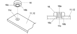
抵抗体13の両側の配線部材11,12の両端部には、少なくともいずれかの配線部材の一面に固定された、該配線部材とは別部材のネジ止め部材(ナット)16を備える。ナット16は雌ネジ部16aを備え、突出部分16cが配線部材11の孔部11cに圧入されて固定されている(図2参照)。なお、配線部材11の孔部11cは突出部16cよりもやや径が小さい。
At both ends of the
従って、配線部材11に孔部11cを備え、ナット16の平坦部分16bは孔部11cの周囲の配線部材11の表面に当接している。そして、ナット16の突出部16cの外周面は孔部11aの内周面に当接している。これら当接面を溶接により固定してもよい。一般に配線部材11,12は柔らかい銅を用いているが、ナット16の平坦部分(面)16bが配線部材11,12の表面と当接する。このため、多少強く締め付けても配線部材11,12を破損させることがない。
Therefore, the
図3はネジ止め部材(ナット)16の変形例を示す。このナット16Aは外周が六角形の面16dによって構成されている。このため、配線部材11には、浅い六角形状の段部11bとその中央に設けた円形の貫通孔11cを備える。ナット16Aには、雌ネジ部16aを備え、六角形の面16dが浅い六角形状の段部11bに圧入されて固定されている。従って、ナット16Aの底面は貫通孔11cの周囲の浅い段部11bの表面に当接し、ナット16Aの側面である面16dは浅い段部11bの内周面に当接していて、これらの当接面を溶接により固定してもよい。
FIG. 3 shows a modification of the screw fixing member (nut) 16. The
図4は実施例1のシャント式電流検出装置の端部を他のバスバーに接続固定する例を示す。配線部材11の端部の貫通孔(不図示)と他の配線部材18の端部の貫通孔18cを位置合わせし、両孔にボルト17を挿通し、その雄ネジ部17aをナット16の雌ネジ部16aに回転締着(ネジ止め)する。
FIG. 4 shows an example in which the end portion of the shunt type current detection device of the first embodiment is connected and fixed to another bus bar. The through hole (not shown) at the end of the
すなわち、配線部材11,12の一面に一方のネジ止め部材(ナット)16が固定され、配線部材11,12の他面に他の配線部材18,19を配置して挟み、他方のネジ止め部材(ボルト)17を上記一方のネジ止め部材(ナット)16に回転締着する。ナット16は配線部材11,12とは別部材であり、配線部材11,12に固定されているので、ナット16の固定作業を要せず、ボルト17のみをナット16に回転締着することで、配線部材18,19を配線部材11,12に接続固定することができる。
That is, one screwing member (nut) 16 is fixed to one surface of the
従って、バスバー端部を他のバスバー等へ接続固定する作業が容易になる。すなわち、ボルトをナットに締着固定するに際して、どちらか一方を固定し、他方を回転締着するのが一般的であるが、電流検出装置10においては、他の配線部材18、19を挟んで、ボルト17の回転締着作業のみで、配線部材11と18および配線部材12と19の接続固定が可能となる。これは、例えばエンジンルーム等の狭い空間等において、ボルト側のみからしか回転締着作業が行えない場合に特に有用である。
Therefore, the work of connecting and fixing the end portion of the busbar to another busbar or the like becomes easy. That is, when the bolt is fastened and fixed to the nut, it is general to fix one of them and rotationally fasten the other, but in the
また、ネジ止め部材が配線部材とは別部材なので、強度を有するネジ止め部材を選択できる。また、配線部材自体の加工が最低限で済む。そして、バスバーの配線機能と、シャント式の電流検出機能を一体化したバスバー状の電流検出装置に適用するので、部品点数を少なくでき、また、接続点数が少なく、高精度な電流検出が可能となる。 Further, since the screwing member is a member different from the wiring member, a screwing member having strength can be selected. Further, the processing of the wiring member itself is minimal. Since it is applied to a busbar-shaped current detection device that integrates the busbar wiring function and the shunt-type current detection function, the number of parts can be reduced, and the number of connection points is small, enabling highly accurate current detection. Become.
図5A−5Bは実施例2の電流検出装置10Aを示し、電圧検出端子14A,14Bの配線部材11,12への固定に、別部材のネジ止め部材の一方(ナット)16を固定した配線部材11,12を用い、別部材のボルト17で締着固定した例である。すなわち、配線部材11には孔部11cに位置合わせしたナット16が溶接等により固定されている。
5A-5B shows the
そして、電圧検出端子14A,14Bには扁平な接続部14aを備え、該接続部には貫通孔14cを備える。そして、電圧検出端子の貫通孔14cを配線部材の孔部11cに位置合わせし、ボルト17の雄ネジ部17aを挿入し、ナット16の雌ネジ部16aに回転締着(ネジ止め)する。従って、ナット16の固定作業は不要で、ボルト17の回転締着作業のみで、電圧検出端子14A,14Bの配線部材11,12への接続固定が可能となる。特に、ボルト側のみからしか回転締着作業が行えない場合に有用である。
The
図6A−6Bは実施例3の電流検出装置10Bを示し、配線部材11,12に設けた電圧検出端子14,15に接続する回路基板20を固定する例である。この実施例においても、配線部材11,12には図示しない貫通孔を備え、該貫通孔に位置合わせして固定したネジ止め部材(ナット)16を、配線部材11,12の下面側に備える。
6A and 6B show a
配線部材の上面側には、図示しない貫通孔を備えた回路基板20が配置され、ボルト17が該貫通孔および配線部材の貫通孔を挿通し、ナット16に回転締着(ネジ止め)する。回路基板20には、配線パターンが形成され、増幅回路、マイコン、信号出力端子、等が搭載される(図示省略)。これにより、電圧検出端子14,15に接続した配線パターンから取り出された検出電圧信号が増幅され、図示しない電圧検出装置に送出される。
A
この装置においても、ナット16の固定作業は不要で、ボルト17の回転締着作業のみで、電圧検出端子14,15に接続する回路基板20を配線部材11,12に容易に固定できる。
Also in this device, the fixing work of the
図7は実施例4の電流検出装置10Cに他のバスバー18,19を接続固定する例を示す。この実施例でも、配線部材11,12の一面(本例では電圧検出端子14,15と反対側の面)にナット16が固定され、配線部材11、12の他面に他のバスバー18,19を配置して挟み、それぞれの貫通孔(例えば配線部材18の貫通孔18c)に挿通してボルト17をナット16に回転締着し、他のバスバー18,19を接続固定することは上記実施例と同様である。
FIG. 7 shows an example in which
しかし、シャント抵抗として構成されたバスバーを、他のバスバー等に接続固定するときに、ネジ止め部材の回転締着によって、シャント抵抗として構成されたバスバーに回転力が作用し、これによって端子材と抵抗体との接合面に応力が加わり、電流検出に誤差が生じるおそれがある。 However, when the bus bar configured as a shunt resistor is connected and fixed to another bus bar or the like, a rotational force acts on the bus bar configured as a shunt resistor due to the rotational fastening of the screw fastening member, whereby the terminal member and Stress may be applied to the joint surface with the resistor, which may cause an error in current detection.
また、シャント抵抗として構成されたバスバーは長尺であるため、例えば、エンジンその他の振動によって、シャント抵抗として構成されたバスバーに振動が生じると、抵抗体は端子材に接合されているので、その界面に振動による応力が印加され、電流検出に誤差が生じるおそれがある。 Further, since the bus bar configured as the shunt resistor is long, for example, when vibration occurs in the bus bar configured as the shunt resistor due to vibration of the engine or the like, the resistor is bonded to the terminal material. Vibrational stress is applied to the interface, which may cause an error in current detection.
そこで、この実施例では、配線部材11,12に固定したナット21と配線部材11,12の貫通孔および配線部材18,19の貫通孔に挿通して、配線部材11、12および18、19を挟み、ボルト22をナット21に回転締着した位置決め部を備える。
Therefore, in this embodiment, the nuts 21 fixed to the
この回転締着を先に行うことで、ボルト17の回転締着に際して、一方の配線部材11,12に対する他方の配線部材18,19の相対的な回転が阻止され、配線部材11,12と18,19を正確に位置合わせし、同一位置に両者を配置して、接続して固定することができる。これにより、抵抗体13と配線部材11,12の接合界面に応力が印加されることを防止でき、電流検出精度の劣化を防止できる。
By performing this rotational fastening first, when the
さらに、この実施例では、ボルト23で配線部材12を固定部24に固定している。配線部材11,12はバスバー状で長尺である。従って、例えばエンジンルーム等に配置すると、エンジンの振動によりバスバー状の電流検出装置に振動が生じる場合がある。そうすると、抵抗体13と配線部材11,12の界面に振動が加わり、電流検出精度の劣化が生じる可能性がある。そこで、長尺の配線部材11,12の中間に静止体への固定部24を設けることで、振動が抵抗体13と配線部材11,12の界面に印加されることを防止でき、電流検出精度の劣化を防止できる。
Further, in this embodiment, the
図8は実施例5の電流検出装置10Dを示す。この実施例は、上述の振動防止のための固定部の変形例である。すなわち、配線部材11に固定したナット25に、配線部材11および固定板材27を挟んでボルト26を回転締着することで、配線部材11の中間部分を静止体である固定板材27に固定した例である。
FIG. 8 shows a
この例においても、バスバー状の電流検出装置10Dに生じる振動を抑制でき、高精度の電流検出を行える。配線部材11の一面に一方のネジ止め部材16,21が固定され、配線部材11の他面に他の配線部材18を配置して挟み、他方のネジ止め部材17,22を上記一方のネジ止め部材16,21に回転締着することは上記実施例と同様である。
Also in this example, the vibration generated in the bus bar-shaped
図9Aと図9Bは実施例6の電流検出装置10Eを示し、図10はその端部を他方のネジ止め部材(ナット)により他のバスバー18,19に接続固定する例である。上述のボルト17とナット16からなるネジ止め部材は、すべてナット16を配線部材11,12に固定したものであった。しかし、実施例6に示すように、ボルト17を配線部材11,12に固定し、他のバスバー18,19を配置して挟み、ナット16の回転締着(ネジ止め)により、他のバスバー18,19を固定するようにしてもよい。
9A and 9B show a
図9Bに示すように、ボルト17は雄ネジ部17aを備え、ナット16の雌ネジ部16a(不図示)が雄ネジ部17aに回転締着する。そして、ボルト17は突出部17cを備え、配線部材11,12に設けた孔部に嵌着し、ボルト17の外周面が配線部材11,12に設けた孔部の内周面に当接する。また、ボルトの平坦面17bは配線部材11,12に設けた孔部の周囲の表面に当接し、これらの当接面を溶接により固定してもよい。
As shown in FIG. 9B, the
従って、この実施例の電流検出装置10Eにおいては、配線部材11,12の一面に一方のネジ止め部材(ボルト)17が固定され、配線部材11,12の他面に他の配線部材18,19を配置して挟み、他方のネジ止め部材(ナット)16を上記一方のネジ止め部材(ボルト)17に回転締着する。これにより、バスバー(配線部材11,12)端部を他のバスバー(配線部材18,19)端部等へ接続固定する作業が容易になることは上記各実施例と同様である。
Therefore, in the
これまで本発明の一実施形態について説明したが、本発明は上述の実施形態に限定されず、その技術的思想の範囲内において種々異なる形態にて実施されてよいことは言うまでもない。 Although one embodiment of the present invention has been described so far, it is needless to say that the present invention is not limited to the above embodiment and may be implemented in various different forms within the scope of the technical idea thereof.
本発明は、バスバー状のシャント式電流検出装置に好適に利用可能である。 INDUSTRIAL APPLICABILITY The present invention can be preferably used for a bus bar-shaped shunt-type current detection device.
Claims (1)
これらの配線部材よりも抵抗温度係数の小さい金属材であって、配線部材と接合された抵抗体と、
少なくともいずれかの配線部材に固定された、該配線部材とは別部材のネジ止め部材と、を備え、
ネジ止め部材は、平坦部分と雌ネジ部と突出部を備えたナットであり、
配線部材に孔部を備え、突出部を孔部内に浅く圧入することにより、ネジ止め部材の平坦部分は、孔部の周囲の配線部材の表面に当接しており、且つ、ネジ止め部材の突出部は、孔部の内周面に当接していて、
一対の配線部材は、いずれか一方または双方に屈曲部を備え、
配線部材の一面に前記ネジ止め部材が固定され、配線部材の他面にバスバーを配置し、これを挟んで他のネジ止め部材が前記ネジ止め部材に回転締着され、
配線部材の抵抗体との接合面と、前記ネジ止め部材の固着部との中間に静止体への固定部を設けた、シャント式電流検出装置。 A pair of wiring members made of a conductive metal material,
A metal material having a smaller temperature coefficient of resistance than these wiring members, and a resistor joined to the wiring members,
A screw member fixed to at least one of the wiring members, which is a member different from the wiring member,
The screwing member is a nut having a flat portion, a female screw portion, and a protruding portion,
By providing the wiring member with the hole and press-fitting the protrusion into the hole shallowly, the flat portion of the screwing member is in contact with the surface of the wiring member around the hole and the screwing member is projected. Part is in contact with the inner peripheral surface of the hole ,
The pair of wiring members includes a bent portion on either one or both sides,
The screwing member is fixed to one surface of the wiring member, the bus bar is arranged on the other surface of the wiring member, and the other screwing member is rotationally fastened to the screwing member while sandwiching the bus bar.
A shunt-type current detecting device , wherein a fixing portion to a stationary body is provided between a joining surface of a wiring member and a resistor and a fixing portion of the screwing member .
Priority Applications (6)
| Application Number | Priority Date | Filing Date | Title |
|---|---|---|---|
| JP2015101880A JP6714974B2 (en) | 2015-05-19 | 2015-05-19 | Current detector |
| US15/572,938 US10473695B2 (en) | 2015-05-19 | 2016-05-13 | Current detection device |
| KR1020177035317A KR102515302B1 (en) | 2015-05-19 | 2016-05-13 | current detection device |
| DE112016002235.2T DE112016002235T5 (en) | 2015-05-19 | 2016-05-13 | Current detection device |
| PCT/JP2016/064256 WO2016186022A1 (en) | 2015-05-19 | 2016-05-13 | Current detection device |
| CN201680028293.1A CN107533891B (en) | 2015-05-19 | 2016-05-13 | Current detection device |
Applications Claiming Priority (1)
| Application Number | Priority Date | Filing Date | Title |
|---|---|---|---|
| JP2015101880A JP6714974B2 (en) | 2015-05-19 | 2015-05-19 | Current detector |
Publications (2)
| Publication Number | Publication Date |
|---|---|
| JP2016217829A JP2016217829A (en) | 2016-12-22 |
| JP6714974B2 true JP6714974B2 (en) | 2020-07-01 |
Family
ID=57320051
Family Applications (1)
| Application Number | Title | Priority Date | Filing Date |
|---|---|---|---|
| JP2015101880A Active JP6714974B2 (en) | 2015-05-19 | 2015-05-19 | Current detector |
Country Status (6)
| Country | Link |
|---|---|
| US (1) | US10473695B2 (en) |
| JP (1) | JP6714974B2 (en) |
| KR (1) | KR102515302B1 (en) |
| CN (1) | CN107533891B (en) |
| DE (1) | DE112016002235T5 (en) |
| WO (1) | WO2016186022A1 (en) |
Families Citing this family (14)
| Publication number | Priority date | Publication date | Assignee | Title |
|---|---|---|---|---|
| HUE046303T2 (en) * | 2016-11-30 | 2020-02-28 | Yuyang Dnu Co Ltd | System for charge-discharge cycler |
| JP6436275B1 (en) * | 2017-01-11 | 2018-12-12 | 株式会社村田製作所 | Current detection device, power supply device |
| JP7288314B2 (en) * | 2018-03-08 | 2023-06-07 | 古河電気工業株式会社 | Shunt structure, current detection device, method for manufacturing current detection device, and method for mounting current detection device |
| JP7184567B2 (en) * | 2018-08-24 | 2022-12-06 | 矢崎総業株式会社 | Busbar with shunt current sensor and shunt resistor |
| CN209055581U (en) * | 2018-09-17 | 2019-07-02 | 宁德时代新能源科技股份有限公司 | Sampling component and battery pack |
| KR102258813B1 (en) * | 2018-11-20 | 2021-05-31 | 주식회사 엘지에너지솔루션 | Hybrid type current measuring device |
| JP7265751B2 (en) * | 2019-02-19 | 2023-04-27 | 株式会社アスター | Method for manufacturing busbar joint |
| JP7288315B2 (en) * | 2019-03-08 | 2023-06-07 | 古河電気工業株式会社 | Shunt structure and current detection device |
| DE102019203496B3 (en) * | 2019-03-14 | 2020-07-16 | Te Connectivity Germany Gmbh | Passive current sensor with simplified geometry |
| DE102019108541A1 (en) * | 2019-04-02 | 2020-10-08 | Eberspächer Controls Landau Gmbh & Co. Kg | Current measuring module |
| JP7399647B2 (en) | 2019-08-19 | 2023-12-18 | 矢崎総業株式会社 | Shunt resistance type current detection device |
| JP2021076435A (en) * | 2019-11-07 | 2021-05-20 | Koa株式会社 | Shut resistance module and mounting structure of shut resistance module |
| DE102020214083A1 (en) * | 2020-11-10 | 2022-05-12 | Continental Automotive Gmbh | Resistor assembly and battery sensor with resistor assembly |
| JP2022123626A (en) * | 2021-02-12 | 2022-08-24 | 住友電装株式会社 | Electrical connection box |
Family Cites Families (17)
| Publication number | Priority date | Publication date | Assignee | Title |
|---|---|---|---|---|
| US906498A (en) | 1907-03-15 | 1908-12-08 | Edward Weston | Shunt or electrical resistance. |
| JPS56156754U (en) * | 1980-04-19 | 1981-11-21 | ||
| JPS5861640U (en) * | 1981-10-21 | 1983-04-26 | トヨタ自動車株式会社 | Installation structure for interior parts in molded ceilings for vehicles |
| JP2738177B2 (en) * | 1991-08-23 | 1998-04-08 | 日産自動車株式会社 | How to build an automobile door |
| CN1319078C (en) | 2003-07-09 | 2007-05-30 | 彭德龙 | Precision shunt resistor and manufacturing method thereof |
| DE102006001874B4 (en) * | 2006-01-13 | 2012-05-24 | Infineon Technologies Ag | Method and device for current and temperature measurement in a power electronic circuit |
| JP2008039571A (en) | 2006-08-04 | 2008-02-21 | Denso Corp | Current sensor |
| DE102010051007A1 (en) * | 2009-12-03 | 2011-06-16 | Koa Corp., Ina-shi | Shunt resistance and manufacturing process therefor |
| KR101233076B1 (en) * | 2010-06-22 | 2013-02-14 | 주식회사 와이즈오토모티브 | Battery sensor of vehicle |
| JP5637364B2 (en) * | 2010-07-29 | 2014-12-10 | 株式会社オートネットワーク技術研究所 | Bolt fastening structure |
| DE102010035485A1 (en) | 2010-08-26 | 2012-03-01 | Isabellenhütte Heusler Gmbh & Co. Kg | Current sense resistor |
| JP5873315B2 (en) * | 2011-12-13 | 2016-03-01 | 矢崎総業株式会社 | Shunt resistance type current sensor |
| JP2013221796A (en) * | 2012-04-13 | 2013-10-28 | Yazaki Corp | Shunt resistor based current sensor |
| KR20150014218A (en) * | 2013-07-29 | 2015-02-06 | 현대모비스 주식회사 | Combination structure of battery sensor module for vehicle |
| JP6177090B2 (en) * | 2013-10-25 | 2017-08-09 | Koa株式会社 | Manufacturing method of current detection device |
| JP6329754B2 (en) * | 2013-11-22 | 2018-05-23 | 矢崎総業株式会社 | Parts with fastening members and their mounting methods |
| JP6637250B2 (en) * | 2015-04-28 | 2020-01-29 | Koa株式会社 | Current detector |
-
2015
- 2015-05-19 JP JP2015101880A patent/JP6714974B2/en active Active
-
2016
- 2016-05-13 US US15/572,938 patent/US10473695B2/en active Active
- 2016-05-13 WO PCT/JP2016/064256 patent/WO2016186022A1/en active Application Filing
- 2016-05-13 DE DE112016002235.2T patent/DE112016002235T5/en active Pending
- 2016-05-13 KR KR1020177035317A patent/KR102515302B1/en active IP Right Grant
- 2016-05-13 CN CN201680028293.1A patent/CN107533891B/en active Active
Also Published As
| Publication number | Publication date |
|---|---|
| DE112016002235T5 (en) | 2018-02-22 |
| US10473695B2 (en) | 2019-11-12 |
| KR102515302B1 (en) | 2023-03-29 |
| CN107533891B (en) | 2019-12-17 |
| CN107533891A (en) | 2018-01-02 |
| JP2016217829A (en) | 2016-12-22 |
| KR20180011136A (en) | 2018-01-31 |
| WO2016186022A1 (en) | 2016-11-24 |
| US20180156844A1 (en) | 2018-06-07 |
Similar Documents
| Publication | Publication Date | Title |
|---|---|---|
| JP6714974B2 (en) | Current detector | |
| WO2016175116A1 (en) | Current detection device | |
| JP6637250B2 (en) | Current detector | |
| JP6305816B2 (en) | Metal plate resistor | |
| JP5117248B2 (en) | Shunt resistor and terminal mounting method to shunt resistor | |
| WO2017203963A1 (en) | Shunt resistor and shunt resistor mounting structure | |
| JP6462233B2 (en) | Current detection structure | |
| WO2015060102A1 (en) | Current detector | |
| WO2018003360A1 (en) | Current measuring device | |
| JP6802645B2 (en) | Shunt type current detector | |
| JP6564482B2 (en) | Metal plate resistor | |
| KR20160026818A (en) | Battery state detection apparatus and method for manufacturing same | |
| JP2008082957A (en) | Shunt resistor | |
| US11061054B2 (en) | Current measuring device | |
| JP5614806B2 (en) | Shunt resistor device | |
| JP2020193845A (en) | Sensor and shunt resistance | |
| JP6687462B2 (en) | Shunt resistor and shunt type current detector | |
| JP2019091824A (en) | Shunt resistor | |
| WO2021246034A1 (en) | Resistor | |
| EP3879276A1 (en) | Shunt sensor | |
| JP2021135140A (en) | Current measurement device | |
| JP2000180251A (en) | Mounting structure of sensing element |
Legal Events
| Date | Code | Title | Description |
|---|---|---|---|
| A621 | Written request for application examination |
Free format text: JAPANESE INTERMEDIATE CODE: A621 Effective date: 20180420 |
|
| A131 | Notification of reasons for refusal |
Free format text: JAPANESE INTERMEDIATE CODE: A131 Effective date: 20190604 |
|
| A521 | Request for written amendment filed |
Free format text: JAPANESE INTERMEDIATE CODE: A523 Effective date: 20190724 |
|
| A02 | Decision of refusal |
Free format text: JAPANESE INTERMEDIATE CODE: A02 Effective date: 20191210 |
|
| A521 | Request for written amendment filed |
Free format text: JAPANESE INTERMEDIATE CODE: A523 Effective date: 20200228 |
|
| A911 | Transfer to examiner for re-examination before appeal (zenchi) |
Free format text: JAPANESE INTERMEDIATE CODE: A911 Effective date: 20200306 |
|
| TRDD | Decision of grant or rejection written | ||
| A01 | Written decision to grant a patent or to grant a registration (utility model) |
Free format text: JAPANESE INTERMEDIATE CODE: A01 Effective date: 20200602 |
|
| A61 | First payment of annual fees (during grant procedure) |
Free format text: JAPANESE INTERMEDIATE CODE: A61 Effective date: 20200608 |
|
| R150 | Certificate of patent or registration of utility model |
Ref document number: 6714974 Country of ref document: JP Free format text: JAPANESE INTERMEDIATE CODE: R150 |
|
| R250 | Receipt of annual fees |
Free format text: JAPANESE INTERMEDIATE CODE: R250 |