JP6705199B2 - Printer - Google Patents

Printer Download PDF

Info

Publication number
JP6705199B2
JP6705199B2 JP2016026142A JP2016026142A JP6705199B2 JP 6705199 B2 JP6705199 B2 JP 6705199B2 JP 2016026142 A JP2016026142 A JP 2016026142A JP 2016026142 A JP2016026142 A JP 2016026142A JP 6705199 B2 JP6705199 B2 JP 6705199B2
Authority
JP
Japan
Prior art keywords
medium
sensor
width
carriage
unit
Prior art date
Legal status (The legal status is an assumption and is not a legal conclusion. Google has not performed a legal analysis and makes no representation as to the accuracy of the status listed.)
Active
Application number
JP2016026142A
Other languages
Japanese (ja)
Other versions
JP2017145077A (en
JP2017145077A5 (en
Inventor
森山 隆司
隆司 森山
前田 浩之
浩之 前田
中澤 篤史
篤史 中澤
六波羅 憲綱
憲綱 六波羅
Current Assignee (The listed assignees may be inaccurate. Google has not performed a legal analysis and makes no representation or warranty as to the accuracy of the list.)
Seiko Epson Corp
Original Assignee
Seiko Epson Corp
Priority date (The priority date is an assumption and is not a legal conclusion. Google has not performed a legal analysis and makes no representation as to the accuracy of the date listed.)
Filing date
Publication date
Application filed by Seiko Epson Corp filed Critical Seiko Epson Corp
Priority to JP2016026142A priority Critical patent/JP6705199B2/en
Priority to US15/421,626 priority patent/US10308050B2/en
Publication of JP2017145077A publication Critical patent/JP2017145077A/en
Publication of JP2017145077A5 publication Critical patent/JP2017145077A5/ja
Application granted granted Critical
Publication of JP6705199B2 publication Critical patent/JP6705199B2/en
Active legal-status Critical Current
Anticipated expiration legal-status Critical

Links

Images

Classifications

    • BPERFORMING OPERATIONS; TRANSPORTING
    • B41PRINTING; LINING MACHINES; TYPEWRITERS; STAMPS
    • B41JTYPEWRITERS; SELECTIVE PRINTING MECHANISMS, i.e. MECHANISMS PRINTING OTHERWISE THAN FROM A FORME; CORRECTION OF TYPOGRAPHICAL ERRORS
    • B41J13/00Devices or arrangements of selective printing mechanisms, e.g. ink-jet printers or thermal printers, specially adapted for supporting or handling copy material in short lengths, e.g. sheets
    • B41J13/0009Devices or arrangements of selective printing mechanisms, e.g. ink-jet printers or thermal printers, specially adapted for supporting or handling copy material in short lengths, e.g. sheets control of the transport of the copy material
    • BPERFORMING OPERATIONS; TRANSPORTING
    • B41PRINTING; LINING MACHINES; TYPEWRITERS; STAMPS
    • B41JTYPEWRITERS; SELECTIVE PRINTING MECHANISMS, i.e. MECHANISMS PRINTING OTHERWISE THAN FROM A FORME; CORRECTION OF TYPOGRAPHICAL ERRORS
    • B41J11/00Devices or arrangements  of selective printing mechanisms, e.g. ink-jet printers or thermal printers, for supporting or handling copy material in sheet or web form
    • B41J11/0025Handling copy materials differing in width
    • B41J11/003Paper-size detection, i.e. automatic detection of the length and/or width of copy material
    • BPERFORMING OPERATIONS; TRANSPORTING
    • B41PRINTING; LINING MACHINES; TYPEWRITERS; STAMPS
    • B41JTYPEWRITERS; SELECTIVE PRINTING MECHANISMS, i.e. MECHANISMS PRINTING OTHERWISE THAN FROM A FORME; CORRECTION OF TYPOGRAPHICAL ERRORS
    • B41J11/00Devices or arrangements  of selective printing mechanisms, e.g. ink-jet printers or thermal printers, for supporting or handling copy material in sheet or web form
    • B41J11/0095Detecting means for copy material, e.g. for detecting or sensing presence of copy material or its leading or trailing end
    • BPERFORMING OPERATIONS; TRANSPORTING
    • B41PRINTING; LINING MACHINES; TYPEWRITERS; STAMPS
    • B41JTYPEWRITERS; SELECTIVE PRINTING MECHANISMS, i.e. MECHANISMS PRINTING OTHERWISE THAN FROM A FORME; CORRECTION OF TYPOGRAPHICAL ERRORS
    • B41J2/00Typewriters or selective printing mechanisms characterised by the printing or marking process for which they are designed
    • B41J2/005Typewriters or selective printing mechanisms characterised by the printing or marking process for which they are designed characterised by bringing liquid or particles selectively into contact with a printing material
    • B41J2/01Ink jet

Description

本発明は、用紙等の媒体を搬送する搬送部と、搬送された媒体に印刷する印刷ヘッドと、媒体の搬送方向と交差する幅方向の側端を検出可能な媒体検出装置とを備えた印刷装置に関する。 The present invention relates to printing including a transport unit that transports a medium such as a sheet, a print head that prints on the transported medium, and a medium detection device that can detect a side edge in the width direction intersecting the transport direction of the medium. Regarding the device.

従来から、この種の印刷装置の一例として、用紙等の媒体を搬送する搬送部と、媒体に印刷する印刷ヘッドとを有する印刷装置が広く知られている(例えば特許文献1等)。
例えば特許文献1には、用紙(媒体の一例)の搬送方向における印刷部よりも上流側の位置で用紙の幅を検出する紙幅検出装置(媒体検出装置の一例)を備えたシリアル方式の印刷装置(シリアルプリンター)が開示されている。この印刷装置は、モーターの駆動により用紙の搬送方向と直交する紙幅方向(主走査方向)に移動して印刷を行う印刷ヘッドを有するキャリッジと、キャリッジにおける印刷ヘッドよりも搬送方向上流側の位置に設けられた2つのセンサー(右側検出器と左側検出器)とを備える。キャリッジが紙幅方向に移動する過程で、右側検出器が用紙の右側端を検出し、左側検出器が用紙の左側端を検出する。
2. Description of the Related Art Conventionally, as an example of this type of printing apparatus, a printing apparatus including a transport unit that transports a medium such as a sheet and a print head that prints on the medium has been widely known (for example, Patent Document 1).
For example, in Patent Document 1, a serial-type printing apparatus including a paper width detection device (an example of a medium detection device) that detects the width of the paper at a position upstream of the printing unit in the conveyance direction of the paper (an example of the medium) (Serial printer) is disclosed. This printing device is provided with a carriage having a print head that moves in the paper width direction (main scanning direction) orthogonal to the paper transport direction by a motor to perform printing, and a position in the carriage that is upstream of the print head in the transport direction. It is provided with two provided sensors (a right side detector and a left side detector). While the carriage is moving in the paper width direction, the right side detector detects the right side edge of the sheet and the left side detector detects the left side edge of the sheet.

特開2001−287405号公報JP, 2001-287405, A

ところで、特許文献1に記載の紙幅検出装置は、シリアル印刷方式の印刷装置に印刷のために主走査方向に移動可能なキャリッジに設けられていたので、例えばライン印刷方式の印刷装置(ラインプリンター)など、印刷用のキャリッジを備えない印刷装置では、印刷用のキャリッジにセンサーを設ける構成は採用できない。また、印刷装置で想定される最大幅の媒体の両側端を検出できる装置を別途組み付ける場合、印刷装置の幅方向サイズの大型化が懸念されるという課題がある。なお、この種の課題は、インクでセンサーが汚れることに起因する検出精度の低下を防止するために、特許文献1のように印刷用のキャリッジにセンサーを備える構成を回避したい場合には、シリアル印刷方式の印刷装置でも概ね共通する。 By the way, since the paper width detection device described in Patent Document 1 is provided in a carriage movable in the main scanning direction for printing in a serial printing type printing device, for example, a line printing type printing device (line printer). For example, in a printing apparatus that does not include a printing carriage, a configuration in which a sensor is provided in the printing carriage cannot be adopted. In addition, when separately assembling a device capable of detecting both side edges of the medium having the maximum width assumed in the printing device, there is a problem that the size of the printing device in the width direction may be increased. It should be noted that this kind of problem is that when it is desired to avoid a configuration in which a sensor for a printing carriage is provided with a sensor as in Patent Document 1, in order to prevent a decrease in detection accuracy due to contamination of the sensor with ink, serial The same applies to printing devices of the printing method.

本発明の目的は、印刷ヘッドが可動か固定かの印刷方式に依存することなく媒体の幅方向の両側端を検出でき、しかも装置の幅方向サイズ寸法を比較的短く抑えることができる印刷装置を提供することにある。 An object of the present invention is to provide a printing apparatus that can detect both side edges in the width direction of a medium without depending on a printing method in which a print head is movable or fixed, and that can reduce the size dimension of the apparatus in the width direction to a relatively short size. To provide.

以下、上記課題を解決するための手段及びその作用効果について記載する。
上記課題を解決する印刷装置は、媒体を搬送する搬送部と、前記媒体に印刷する印刷ヘッドと、前記印刷ヘッドよりも前記媒体の搬送方向の上流側に配置されるとともに前記媒体の前記搬送方向と交差する幅方向の側端を検出する媒体検出部と、前記搬送部、前記印刷ヘッド、前記媒体検出部を制御する制御部とを備え、前記媒体検出部は、前記印刷ヘッドよりも搬送方向の上流側の位置で前記幅方向に移動可能なキャリッジと、前記キャリッジにおける前記幅方向の異なる位置に設けられた2つのセンサーと、を備え、前記制御部は、前記媒体検出部を制御して前記キャリッジを移動させることで前記センサーに前記媒体の前記幅方向の側端を検出させる。
Hereinafter, the means for solving the above problems and the effects thereof will be described.
A printing apparatus that solves the above-described problems, a transport unit that transports a medium, a print head that prints on the medium, and a transport direction of the medium that is arranged upstream of the print head in the transport direction of the medium. A medium detection unit that detects a side edge in the width direction that intersects with the conveyance unit, the print head, and a control unit that controls the medium detection unit, and the medium detection unit is in the conveyance direction relative to the print head. of the carriages move to the previous SL width direction at a location upstream, and a two sensors provided at different positions in the width direction of the carriage, the control unit controls the medium detecting unit The carriage is moved so that the sensor detects the side edge of the medium in the width direction.

この構成によれば、媒体検出のキャリッジには2つのセンサーが幅方向の異なる位置に配置されているので、媒体の幅方向の側端を検出する際に2つのセンサーを使い分けることにより、側端を検出する際のキャリッジの移動量を少なく済ませられる。よって、印刷ヘッドが可動か固定かの印刷方式に依存することなく媒体の幅方向の両側端を検出でき、しかも媒体検出部を設けた割に、印刷装置の幅方向サイズ寸法を比較的短く抑えることができる。 According to this configuration, since the two sensors are arranged at different positions in the width direction on the carriage of the medium detection unit , the two sensors can be selectively used when detecting the side edge of the medium in the width direction. It is possible to reduce the movement amount of the carriage when detecting the edge. Therefore, both side edges in the width direction of the medium can be detected without depending on the printing method in which the print head is movable or fixed, and the size dimension in the width direction of the printing apparatus is kept relatively short despite the provision of the medium detection unit. be able to.

上記印刷装置において、前記キャリッジは、前記搬送部により搬送される媒体の搬送経路に対して前記印刷ヘッド側とは反対側の位置で前記幅方向に移動可能に設けられ、前記2つのセンサーは、前記搬送経路を挟んで前記印刷ヘッド側とは反対側の位置から媒体に向かって光を照射する光学式センサーであることが好ましい。 In the above printing apparatus, the carriage is provided movably in the width direction at a position opposite to the print head side with respect to a transport path of a medium transported by the transport unit, and the two sensors are It is preferable that the optical sensor is an optical sensor that irradiates light toward a medium from a position opposite to the print head side with the transport path interposed therebetween.

この構成によれば、キャリッジが、媒体の搬送経路に対して印刷ヘッド側とは反対側の位置において幅方向に移動することによって、光学式センサーからなる2つのセンサーは、搬送経路を挟んで印刷ヘッド側とは反対側の位置から媒体に向かって光を照射することで媒体の側端を検出する。2つのセンサーは媒体に対して印刷ヘッドとは反対側の位置を移動するので、媒体に対して印刷ヘッドと同じ側に配置される構成の場合に比べ、印刷ヘッドからのインクが付着しにくい。そのため、インク汚れに起因するセンサーの検出精度の低下を回避し易い。 According to this configuration, the carriage moves in the width direction at the position opposite to the print head side with respect to the medium transport path, so that the two sensors, which are optical sensors, print while sandwiching the transport path. The side edge of the medium is detected by irradiating the medium with light from a position opposite to the head side. Since the two sensors move to a position on the side opposite to the print head with respect to the medium, ink from the print head is less likely to adhere to the medium as compared with the case where the two sensors are arranged on the same side as the print head with respect to the medium. Therefore, it is easy to avoid a decrease in sensor detection accuracy due to ink stains.

上記印刷装置では、前記媒体検出部は、前記キャリッジ及び前記センサーを収容する筐体を備え、前記筐体は、前記搬送経路を搬送される媒体を支持する媒体支持部を有し、前記媒体支持部は、前記2つのセンサーからの光を透過可能な窓部を有することが好ましい。 In the above printing apparatus, the medium detection unit includes a housing that accommodates the carriage and the sensor, and the housing includes a medium support unit that supports a medium transported through the transport path. It is preferable that the section has a window section that can transmit light from the two sensors.

この構成によれば、媒体検出部の筐体には、搬送経路を搬送される媒体とセンサーの移動経路との間に、センサーからの光を透過可能な窓部を有する媒体支持部が設けられているので、センサーが媒体から出た紙粉等の塵埃や印刷ヘッドからのインクミスト等からセンサーを保護しつつ、窓部を通してセンサーにより媒体の側端を検出できる。また、窓部が媒体支持部の一部を兼ねているので、センサーと媒体との距離をほぼ一定に保つことができ、この点からもセンサーの検出精度を高く維持できる。 According to this configuration, the housing of the medium detection unit is provided with the medium support unit having the window portion through which the light from the sensor can pass, between the medium conveyed on the conveyance path and the movement path of the sensor. Therefore, the side edge of the medium can be detected by the sensor through the window while the sensor protects the sensor from dust such as paper dust emitted from the medium and ink mist from the print head. Further, since the window portion also serves as a part of the medium support portion, the distance between the sensor and the medium can be kept substantially constant, and from this point as well, the detection accuracy of the sensor can be maintained high.

上記印刷装置において、前記媒体支持部には、前記窓部が前記幅方向に沿って複数設けられていることが好ましい。
この構成によれば、媒体支持部におけるセンサーの移動エリアに相当する部分には、窓部が幅方向に沿って複数配置されているので、移動エリアに亘る1つの長い窓部を設けた構成に比べ、媒体支持部の強度を比較的高く確保できる。
In the above printing apparatus, it is preferable that the medium supporting unit is provided with a plurality of windows along the width direction.
According to this configuration, a plurality of windows are arranged in the width direction in the portion corresponding to the movement area of the sensor in the medium supporting portion, so that a configuration in which one long window portion is provided over the movement area is provided. In comparison, the strength of the medium supporting portion can be ensured to be relatively high.

上記印刷装置において、複数の前記窓部は、前記2つのセンサーが最小幅から最大幅までの媒体の両側の側端をそれぞれ異なる前記窓部を通して検出可能な位置に設けられていることが好ましい。 In the above printing apparatus, it is preferable that the plurality of windows are provided at positions where the two sensors can detect side edges on both sides of the medium having a minimum width to a maximum width through different windows.

この構成によれば、2つのセンサーによって最小幅から最大幅までの媒体の両側の側端をそれぞれ異なる窓部を通して検出できる。例えば最小幅から最大幅までの媒体の両側の側端を連続的に検出できる。 With this configuration, the two sensors can detect the side edges on both sides of the medium from the minimum width to the maximum width through different windows. For example, the side edges on both sides of the medium from the minimum width to the maximum width can be continuously detected.

上記印刷装置において、前記キャリッジを移動させる動力源を備え、前記動力源は、ステッピングモーターであることが好ましい。
この構成によれば、動力源がステッピングモーターであるので、直流モーター(DCモーター)を用いた場合に必要な、エンコーダー等が不要なので、直流モーターを使用した場合に比べ、媒体検出部の部品点数を少なく抑えることができる。例えば媒体検出部のサイズの小型化を実現し易い。
In the printing apparatus, it is preferable that a power source for moving the carriage is provided, and the power source is a stepping motor.
According to this configuration, since the power source is the stepping motor, the encoder and the like required when using the DC motor (DC motor) are not required. Therefore, the number of parts of the medium detection unit is larger than that when the DC motor is used. Can be kept low. For example easily downsized size of the medium detecting unit.

上記印刷装置において、前記キャリッジが移動可能な前記幅方向を左右方向とすると、前記媒体が最大幅の媒体である場合、前記キャリッジが移動可能範囲における左側の端部位置にあるとき、2つの前記センサーのうち右側の前記センサーは前記最大幅の媒体を検知し、左側の前記センサーは前記最大幅の媒体を検知せず、一方、前記キャリッジが移動可能範囲における右側の端部位置にあるとき、2つの前記センサーのうち左側の前記センサーは前記最大幅の媒体を検知し、右側の前記センサーは前記最大幅の媒体を検知しないことが好ましい。 In the above printing apparatus, when the carriage is to the width direction movable lateral direction, if the medium is a medium of the maximum width, when the carriage is in the end portion location of the left side of the movable range, two of the when the right of the sensor of the sensor detects the medium of the maximum width, the left side of the sensor does not detect the medium of the maximum width, whereas, the said carriage to the right end region location in the movable range, It is preferable that the sensor on the left side of the two sensors detects the medium having the maximum width, and the sensor on the right side does not detect the medium having the maximum width.

この構成によれば、最大幅の媒体であるとき、キャリッジが左側の端部位置にあるとき左側のセンサーのみが媒体から幅方向の外側へ外れ、キャリッジが右側の端部位置にあるとき右側のセンサーのみが媒体から幅方向の外側へ外れる。つまり、キャリッジの左右の端部位置間の移動可能範囲が最大幅の媒体の幅の割に相対的に短いので、媒体検出部を設けた印刷装置の幅方向のサイズ寸法を比較的短く抑えられる。また、媒体が最大幅の媒体である場合、媒体の左側の側端を左側のセンサーで検出し、媒体の右側の側端を右側のセンサーで検出することにより、最大幅の媒体の両側端を検出できる。 According to this arrangement, when a medium of the maximum width, the carriage is only the left sensor when the end portion location of the left out to the outside in the width direction from the medium, the right when the carriage is at the right end portion location Only the sensor is detached from the medium outward in the width direction. That is, since the movable range of the end portion置間of the left and right carriage is relatively short despite the width of the medium a maximum width, is suppressed relatively short width direction of the size dimensions of a printing apparatus provided with a media detecting unit .. When the medium has the maximum width, the left side edge of the medium is detected by the left side sensor, and the right side edge of the medium is detected by the right side sensor. Can be detected.

上記印刷装置において、前記キャリッジが移動する前記幅方向を左右方向とした場合、前記制御部は、前記媒体検出部を制御して前記キャリッジを前記幅方向に移動させて、前記媒体の左側端を左側の前記センサーに検出させ、前記媒体の右側端を右側の前記センサーに検出させることが好ましい。 In the above printing apparatus, when the width direction in which the carriage moves is the left-right direction, the control unit controls the medium detection unit to move the carriage in the width direction so that the left end of the medium is moved. It is preferable that the sensor on the left side detects the right end of the medium and the sensor on the right side detects the right end.

この構成によれば、媒体の左側端は左側のセンサーによって検出され、媒体の右側端は右側のセンサーによって検出される。よって、媒体の幅方向の両側端を検出する際にキャリッジに必要な移動距離を相対的に短く済ませられる。そのため、媒体検出部の幅方向のサイズ寸法を相対的に短くできる。例えば媒体検出部を設けた割に、印刷装置の幅方向サイズ寸法が相対的に長くなることを回避できるうえ、媒体の幅方向に関する媒体情報の取得所要時間を相対的に短く抑えることができる。 According to this configuration, the left end of the medium is detected by the left sensor, and the right end of the medium is detected by the right sensor. Therefore, the moving distance required for the carriage when detecting both side edges of the medium in the width direction can be relatively short. Therefore, the size of the medium detection unit in the width direction can be relatively shortened. For example, although the medium detection unit is provided, it is possible to prevent the size of the printing apparatus in the width direction from becoming relatively long, and it is possible to relatively reduce the time required to acquire the medium information in the width direction of the medium.

上記印刷装置において、前記媒体の幅情報を取得する幅情報取得部を更に備え、前記制御部は、前記幅情報に基づく媒体の幅が設定幅よりも長い場合、前記媒体の左側端を左側の前記センサーに検出させ、前記媒体の右側端を右側の前記センサーに検出させるように前記媒体検出部を制御することが好ましい。 In the printing device, further comprising a width information acquisition unit for acquiring the width information of the medium, the control unit, if the width of the medium based on the width information is longer than the set width, the left end of the medium It is preferable that the medium detector is controlled so that the sensor detects the medium and the right side edge of the medium is detected by the sensor on the right side.

この構成によれば、幅情報に基づく幅が設定幅よりも長い場合、この媒体の左側端が左側のセンサーに検出され、媒体の右側端が右側のセンサーに検出される。よって、媒体の両側端を検出する際にキャリッジに必要な移動距離を相対的に短く済ませられる。この結果、媒体検出部の幅方向のサイズ寸法を短くできるうえ、媒体情報の取得所要時間を相対的に短く抑えることができる。 According to this configuration, when the width based on the width information is longer than the set width, the left end of the medium is detected by the left sensor and the right end of the medium is detected by the right sensor. Therefore, the moving distance required for the carriage when detecting both side edges of the medium can be relatively short. As a result, the size of the medium detection unit in the width direction can be shortened, and the time required to acquire the medium information can be relatively shortened.

上記印刷装置において、前記媒体の幅情報を取得する幅情報取得部を更に備え、前記制御部は、前記幅情報に基づく媒体の幅が設定幅以下の場合、1つの前記センサーを用いて、前記媒体の幅方向の両方の側端を検出させ、前記制御部は、前記幅情報に基づく媒体の幅が設定幅よりも長い場合、2つの前記センサーを用いて、前記媒体の幅方向の両方の側端を検出させることが好ましい。
上記印刷装置では、前記センサーは光反射型センサーであり、前記搬送部により搬送される前記媒体の搬送経路を挟んで前記センサーの移動経路と対向する位置には、前記搬送経路に沿って前記媒体を案内する媒体案内部材が配置され、前記媒体案内部材は前記センサーの移動経路と対向する部分が光を反射する反射面となっていることが好ましい。
The printing apparatus further includes a width information acquisition unit that acquires width information of the medium, and the control unit uses one of the sensors when the width of the medium based on the width information is equal to or less than a set width. If both sides of the medium in the width direction are detected, and the width of the medium based on the width information is longer than the set width, the controller uses two sensors to detect both sides in the width direction of the medium. It is preferable to detect the side edge.
In the printing apparatus, the sensor is a light-reflective sensor, and the medium is conveyed along the conveyance path at a position facing the movement path of the sensor with the conveyance path of the medium conveyed by the conveyance section interposed therebetween. It is preferable that a medium guiding member that guides light is disposed, and that the medium guiding member has a reflection surface that reflects light in a portion facing the movement path of the sensor.

この構成によれば、媒体案内部材におけるセンサーの移動経路と対向する部分が光を反射する反射面となっている。このため、光反射面専用の部材を別途設ける必要がないので、搬送部の媒体案内構造を比較的コンパクトに構成できる。 According to this structure, the portion of the medium guiding member that faces the movement path of the sensor is a reflecting surface that reflects light. Therefore, it is not necessary to separately provide a member dedicated to the light reflecting surface, so that the medium guiding structure of the transport unit can be configured to be relatively compact.

上記印刷装置において、前記媒体案内部材は金属からなることが好ましい。
この構成によれば、金属からなる媒体案内部材のセンサーの移動経路と対向する部分に研磨やめっき等の加工を加えることによって、光を反射する反射面を比較的簡単に形成できる。
In the printing device, it is preferable that the medium guiding member is made of metal.
According to this configuration, the reflection surface that reflects light can be formed relatively easily by applying processing such as polishing or plating to the portion of the medium guide member made of metal that faces the movement path of the sensor.

上記印刷装置において、前記制御部は、前記搬送部が媒体を搬送していないときに、前記センサーの検出信号が、媒体がないときの検出値をとれば当該センサーを正常とし、媒体があるときの検出値をとれば当該センサーを故障とすることが好ましい。 In the above printing apparatus, the control unit normalizes the sensor if the detection signal of the sensor has a detection value when there is no medium when the conveyance unit is not conveying the medium, and when the medium is present. It is preferable that the sensor be out of order if the detected value is taken.

この構成によれば、媒体を搬送していないときに、センサーが反射面からの反射光を受光せず、媒体があるときの検出値をとれば、センサーは故障とされる。よって、故障したセンサーの検出信号に基づき間違った媒体の側端を検出する不都合を極力回避できる。 According to this configuration, when not carrying a medium, the sensor does not receive reflected light from the reflection surface, taking the detection value when there is a medium, the sensor is a failure. Therefore, the inconvenience of detecting the wrong side edge of the medium based on the detection signal of the failed sensor can be avoided as much as possible.

上記印刷装置において、前記制御部は、2つの前記センサーのうち一方が故障である場合、他方のセンサーで媒体の両側端を検出することが好ましい。
この構成によれば、一方のセンサーが故障である場合、他方のセンサーで媒体の両側端を検出するので、一方のセンサーが故障しても、媒体の両側端位置を取得できる。
In the above printing apparatus, it is preferable that, when one of the two sensors is out of order, the control unit detects the both ends of the medium by the other sensor.
According to this configuration, when one sensor is out of order, the other sensor detects both side edges of the medium, so that even if one sensor fails, both side edge positions of the medium can be acquired.

上記印刷装置において、前記媒体の幅情報を取得する幅情報取得部を備え、前記制御部は、2つの前記センサーのうち一方の前記センサーが故障である場合、前記幅情報に基づく前記媒体の幅が設定幅以下であれば、他方の前記センサーで前記媒体の両側端を検出することが好ましい。 In the printing apparatus, a width information acquisition unit that acquires width information of the medium is provided, and the control unit, when one of the two sensors is defective, the width of the medium based on the width information. Is less than or equal to the set width, it is preferable that the other sensor detects both side edges of the medium.

この構成によれば、一方のセンサーが故障である場合、幅情報に基づく媒体の幅が設定幅以下であれば、他方のセンサーで媒体の両側端を検出する。よって、一方のセンサーが故障しても、設定幅以下の幅を有する媒体については、両側端位置を取得できる。 According to this configuration, when one of the sensors is out of order and the width of the medium based on the width information is less than or equal to the set width, the other sensor detects both side edges of the medium. Therefore, even if one of the sensors fails, both side edge positions can be acquired for a medium having a width equal to or smaller than the set width.

上記印刷装置において、前記制御部は、2つの前記センサーのうち一方の前記センサーが故障である場合、前記幅情報に基づく媒体の幅が前記設定幅よりも大きければ、他方の前記センサーで前記媒体の両側端のうち一方の側端を検出し、当該一方の側端の検出結果と前記幅情報とに基づいて他方の側端の位置を推定することが好ましい。 In the printing apparatus, when one of the two sensors has a failure, the control unit causes the other sensor to use the medium if the width of the medium based on the width information is larger than the set width. It is preferable to detect one of the two side edges and to estimate the position of the other side edge based on the detection result of the one side edge and the width information.

この構成によれば、一方のセンサーが故障である場合、幅情報に基づく媒体の幅が設定幅よりも大きければ、他方のセンサーで媒体の両側端のうち一方の側端を検出し、当該一方の側端の検出結果と幅情報とに基づいて他方の側端の位置を推定する。よって、一方のセンサーが故障した際に、他方のセンサーで両側端を検出できないほど幅の大きな媒体についても、両側端位置を取得できる。 According to this configuration, in the case where one of the sensors is out of order and the width of the medium based on the width information is larger than the set width, the other sensor detects one of the both side edges of the medium and The position of the other side edge is estimated based on the detection result of the side edge and the width information. Therefore, when one of the sensors fails, it is possible to acquire the both-end position even for a medium having a width that is too wide for the other sensor to detect.

一実施形態における印刷装置を示す斜視図。FIG. 3 is a perspective view illustrating a printing device according to an embodiment. 印刷装置の模式断面図。FIG. 3 is a schematic cross-sectional view of a printing device. カバーを開けた状態にある印刷装置の斜視図。FIG. 3 is a perspective view of the printing apparatus with a cover open. カバーを開けた状態における本体側給送機構部とカバー側給送機構部とを示す斜視図。FIG. 3 is a perspective view showing a main body side feeding mechanism section and a cover side feeding mechanism section with a cover opened. 給送機構を示す側断面図。The sectional side view which shows a feeding mechanism. 給送機構の一部を示す側断面図。FIG. 3 is a side sectional view showing a part of the feeding mechanism. カバーを開けた状態における本体側給送機構部とカバー側給送機構部とを示す側断面図。FIG. 3 is a side sectional view showing a main body side feeding mechanism section and a cover side feeding mechanism section in a state where a cover is opened. 媒体検出装置及びその周辺部分を示す斜視図。FIG. 3 is a perspective view showing a medium detection device and its peripheral portion. 媒体検出装置を示す斜視図。FIG. 3 is a perspective view showing a medium detection device. 媒体検出装置を示す分解斜視図。FIG. 3 is an exploded perspective view showing the medium detection device. 媒体検出装置のカバーを取り外した状態を示す平面図。FIG. 4 is a plan view showing a state where the cover of the medium detection device is removed. 媒体検出装置を裏面側から見た斜視図。The perspective view which looked at the medium detection device from the back side. ホーム位置にある状態のキャリッジを示す平面図。FIG. 3 is a plan view showing the carriage in the home position. 媒体検出装置の要部を示す図13における14−14線断面図。FIG. 14 is a sectional view taken along line 14-14 in FIG. 13 showing a main part of the medium detection device. 媒体検出装置の要部を示す図13における15−15線断面図。FIG. 15 is a sectional view taken along line 15-15 in FIG. 13 showing a main part of the medium detection device. 印刷装置の電気的構成を示すブロック図。FIG. 3 is a block diagram showing an electrical configuration of the printing apparatus. 媒体検出装置における媒体側端検出処理を説明する模式平面図。FIG. 6 is a schematic plan view illustrating a medium side edge detection process in the medium detection device. 小サイズの媒体の側端検出処理を説明する各センサーの信号波形図。The signal waveform diagram of each sensor explaining the side edge detection processing of a small size medium. 大サイズの媒体の側端検出処理を説明する各センサーの信号波形図。The signal waveform diagram of each sensor explaining the side edge detection processing of a large size medium. 媒体側端検出処理ルーチンを示すフローチャート。The flowchart which shows a medium side edge detection processing routine. 故障時の媒体側端検出処理ルーチンを示すフローチャート。9 is a flowchart showing a medium side edge detection processing routine at the time of failure.

以下、印刷装置の一実施形態について図面を参照して説明する。
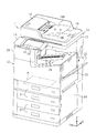
図1に示すように、印刷装置11は、用紙等の媒体Pに印刷する印刷機能を有するプリンター部12と、プリンター部12の上側に配置されたスキャナー部13とを備え、全体として鉛直方向Zに長い略直方体状をなす複合機からなる。プリンター部12の上面部にはスキャナー部13の隣(図1では手前側)の位置に、操作パネル14が設けられている。操作パネル14は、例えばタッチパネル機能を有する表示部15を備える。本例では、タッチパネルが操作部16の一例を構成する。なお、操作部16は、操作スイッチでもよい。
Hereinafter, an embodiment of a printing apparatus will be described with reference to the drawings.
As shown in FIG. 1, the printing device 11 includes a printer unit 12 having a printing function of printing on a medium P such as paper, and a scanner unit 13 arranged on the upper side of the printer unit 12, and as a whole, in the vertical direction Z. It consists of a complex machine with a long rectangular parallelepiped shape. An operation panel 14 is provided on the upper surface of the printer unit 12 adjacent to the scanner unit 13 (on the front side in FIG. 1). The operation panel 14 includes a display unit 15 having a touch panel function, for example. In this example, the touch panel constitutes an example of the operation unit 16. The operation unit 16 may be an operation switch.

図1に示すように、スキャナー部13は、上面が不図示の原稿台となったスキャナー本体部17と、スキャナー本体部17の上面(原稿台ガラス面)に対して開閉可能に設けられた原稿台カバー18とを備える。原稿台カバー18の上部には、自動原稿給送部19(オートドキュメントフィーダー(ADF))が搭載されている。 As shown in FIG. 1, the scanner unit 13 includes a scanner main body 17 whose upper surface serves as a document table (not shown), and an original document that is openable and closable with respect to the upper surface (original table glass surface) of the scanner main body unit 17. The base cover 18 is provided. An automatic document feeder 19 (auto document feeder (ADF)) is mounted on the document table cover 18.

スキャナー部13は、原稿台カバー18を開けて不図示の原稿台ガラス上にセットした原稿を読み取る不図示の読取部を有する。自動原稿給送部19は載置台19Aにセットされた複数枚の原稿を1枚ずつ順番に給送し、読取部によりスキャニングされ後の原稿はスタック部19B上に順次排出される。このように構成された印刷装置11は、前述の原稿台と操作パネル14とを上面部に有する略直方体状の本体20と原稿台カバー18とを備える。 The scanner unit 13 has a reading unit (not shown) that opens the document table cover 18 and reads a document set on a platen glass (not shown). The automatic document feeder 19 sequentially feeds a plurality of documents set on the mounting table 19A one by one, and the documents scanned by the reading unit are sequentially discharged onto the stack unit 19B. The printing apparatus 11 configured in this way includes a main body 20 having a substantially rectangular parallelepiped shape having the above-described document table and the operation panel 14 on the upper surface, and the document table cover 18.

図1に示すように、プリンター部12の下部には、複数枚の媒体Pを積載状態に載置して収容可能なカセット21が、本体20に対して正面側から挿抜可能な状態で上下方向に複数段挿着されている。また、本体20の一側部には、給送トレイ22が下端を中心に開閉可能に設けられている。給送トレイ22を図1に二点鎖線で示す開いた状態とし、その上に印刷するべき媒体Pをセットすることが可能となっている。また、本体20の一側部には、給送トレイ22を含むメンテナンス用のカバー23と、カバー23よりも下側に配置されたメンテナンス用のカバー24とが、それぞれ一側端を中心に横開きで開閉可能に設けられている。なお、本実施形態では、カセット21と給送トレイ22とが、媒体載置部の一例をそれぞれ構成する。給送トレイ22は、1枚の媒体Pのみをセットできる手差しトレイでもよいし、複数の媒体を積載状態にセットでき自動で1枚ずつ給送可能なホッパー機能付きの構成でもよい。 As shown in FIG. 1, a cassette 21 capable of accommodating and accommodating a plurality of media P in a stacked state is provided in a lower portion of the printer unit 12 in a vertical direction in a state where the cassette 21 can be inserted into and removed from the front side of the body 20. It is inserted in multiple stages. A feed tray 22 is provided on one side of the main body 20 so as to be openable and closable around the lower end. It is possible to set the feeding tray 22 in the open state shown by the chain double-dashed line in FIG. 1 and set the medium P to be printed on it. Further, on one side of the main body 20, a maintenance cover 23 including the feeding tray 22 and a maintenance cover 24 arranged below the cover 23 are arranged laterally around one side end. It is openable and can be opened and closed. In the present embodiment, the cassette 21 and the feeding tray 22 respectively constitute an example of the medium stacking unit. The feeding tray 22 may be a manual feeding tray that can set only one medium P, or may have a configuration with a hopper function that can set a plurality of media in a stacked state and can automatically feed one by one.

また、プリンター部12においてカセット21よりも上側の部分が、カセット21又は給送トレイ22から給送された媒体Pに印刷する印刷機構部25(図2参照)となっている。プリンター部12とスキャナー本体部17との間には印刷後の媒体が排出されるスタッカー部26が設けられている。 Further, a portion of the printer unit 12 above the cassette 21 is a printing mechanism unit 25 (see FIG. 2) that prints on the medium P fed from the cassette 21 or the feeding tray 22. A stacker unit 26 for ejecting the medium after printing is provided between the printer unit 12 and the scanner body unit 17.

次に図2を参照してプリンター部12の詳細な構成を説明する。なお、図2では、カセット21は最上段のもののみを示し、他の段のものは省略している。また、印刷ヘッド34に印刷されるときの媒体Pが搬送される方向を搬送方向Yとし、搬送方向Yと交差(特にば直交)する方向を幅方向Xとする。 Next, a detailed configuration of the printer unit 12 will be described with reference to FIG. In FIG. 2, only the uppermost cassette 21 is shown, and the other cassettes are omitted. Further, a direction in which the medium P is printed when printed on the print head 34 is defined as a carrying direction Y, and a direction intersecting (particularly orthogonal to) the carrying direction Y is defined as a width direction X.

図2に示すように、本実施形態の印刷装置11の本体20内には、前述の印刷機構部25が設けられている。印刷機構部25は、媒体Pを搬送路31に沿って搬送する搬送部の一例としての搬送ユニット32と、搬送途中の媒体Pに印刷する印刷ヘッド34を有する印刷ユニット33とが設けられている。 As shown in FIG. 2, the printing mechanism unit 25 described above is provided in the main body 20 of the printing apparatus 11 of the present embodiment. The printing mechanism unit 25 is provided with a transport unit 32 as an example of a transport unit that transports the medium P along the transport path 31, and a printing unit 33 having a print head 34 that prints on the medium P that is being transported. ..

印刷ヘッド34は、インクを吐出するインクジェット方式を採用する。印刷ヘッド34は、図1の紙面と直交する幅方向Xに最大幅の媒体Pの幅よりも少し長く延びる長尺状のラインヘッドからなり、幅方向Xへの移動が不能に所定位置に固定された固定式である。本実施形態では、固定式のラインヘッドからなる印刷ヘッド34により、搬送中の媒体Pに対してその幅方向Xに亘る範囲にインク滴を一斉に吐出してライン状に印刷を進めるライン印刷方式を採用している。この印刷ヘッド34から吐出されたインクが媒体Pに付着することにより、媒体Pに画像又は文書等が印刷される。なお、印刷ユニット33が幅方向Xに移動可能な印刷用のキャリッジを備え、その印刷用のキャリッジに設けられた印刷ヘッド34が、印刷用のキャリッジと共に幅方向X(主走査方向)に移動する移動式で、媒体Pの搬送動作と印刷ヘッド34による印刷動作とが交互に行われるあるシリアル印刷方式を採用することもできる。 The print head 34 employs an inkjet method that ejects ink. The print head 34 is composed of a long line head that extends a little longer than the width of the medium P having the maximum width in the width direction X orthogonal to the paper surface of FIG. 1, and is fixed at a predetermined position so that it cannot move in the width direction X. It is a fixed type. In the present embodiment, a line printing method in which a print head 34 including a fixed line head ejects ink droplets simultaneously to a medium P being conveyed in a range extending in the width direction X to perform linear printing. Has been adopted. The ink ejected from the print head 34 adheres to the medium P, so that an image, a document, or the like is printed on the medium P. The printing unit 33 includes a printing carriage that can move in the width direction X, and the print head 34 provided on the printing carriage moves in the width direction X (main scanning direction) together with the printing carriage. It is also possible to employ a certain serial printing method which is a moving method and in which the conveyance operation of the medium P and the printing operation by the print head 34 are alternately performed.

また、図2に示すように、搬送ユニット32は、媒体Pを給送する給送機構部35と、媒体Pを印刷ユニット33が印刷を行うときの搬送路36に沿って搬送する搬送機構部37と、印刷済みの媒体Pを排出路62に沿って搬送してスタッカー部26へ排出する排出機構部38とを備えている。 Further, as shown in FIG. 2, the transport unit 32 includes a feeding mechanism unit 35 that feeds the medium P, and a transport mechanism unit that transports the medium P along a transport path 36 when the printing unit 33 prints. 37, and a discharge mechanism section 38 that conveys the printed medium P along the discharge path 62 and discharges it to the stacker section 26.

給送機構部35は、給送トレイ22を給送元とする第1給送部41と、カセット21を給送元とする第2給送部42と、両面印刷時に片面の印刷を終えた媒体Pを再び搬送路36へ給送する第3給送部43とを有している。第1給送部41は、給送トレイ22上にセットされて先端部が挿入口20Aから挿入された状態にある媒体Pを、第1給送ローラー対44の回転によって、第1給送路45に沿って搬送機構部37へ給送する。なお、給送トレイ22を備えたカバー23(図1、図3を参照)は、本体20における印刷ヘッド34よりも搬送方向Yの上流側の位置に開閉可能に設けられている。 The feeding mechanism unit 35 has a first feeding unit 41 having a feeding tray 22 as a feeding source, a second feeding unit 42 having a cassette 21 as a feeding source, and has finished printing one side of a sheet during duplex printing. It has a third feeding section 43 that feeds the medium P to the transport path 36 again. The first feeding unit 41 rotates the first feeding roller pair 44 to feed the medium P that is set on the feeding tray 22 and has the leading end inserted from the insertion opening 20A. The sheet is fed along the line 45 to the transport mechanism section 37. The cover 23 (see FIGS. 1 and 3) provided with the feeding tray 22 is openably and closably provided at a position upstream of the print head 34 in the main body 20 in the transport direction Y.

また、第2給送部42は、カセット21から媒体Pを第2給送路48に沿って給送する。第2給送部42は、カセット21内の最上位の媒体Pを送り出すピックアップローラー49と、送り出された媒体Pを1枚に分離する分離ローラー対50と、分離された1枚の媒体Pを給送する第2給送ローラー対51及び従動ローラー52とを備える。 The second feeding unit 42 also feeds the medium P from the cassette 21 along the second feeding path 48. The second feeding unit 42 picks up the uppermost medium P in the cassette 21, a pickup roller 49, a separation roller pair 50 that separates the discharged medium P into one sheet, and one separated medium P. A second feeding roller pair 51 and a driven roller 52 for feeding are provided.

図2に示すように、搬送機構部37は、第1〜第3給送部41〜43の合流箇所よりも少し搬送方向Yの下流側の位置に配置された搬送ローラー対46と、印刷ヘッド34と対向する位置に配置されたベルト搬送機構58とを備える。媒体Pは停止中の搬送ローラー対46に先端が突き当てられることにより給送過程でスキュー取りされ、スキュー取り後の媒体Pが搬送ローラー対46の回転によって搬送路36へ搬送される。 As shown in FIG. 2, the transport mechanism unit 37 includes a transport roller pair 46 disposed at a position slightly downstream of the confluence of the first to third feeding units 41 to 43 in the transport direction Y, and a print head. 34 and a belt transport mechanism 58 arranged at a position facing each other. The medium P is skewed in the feeding process by the front end abutting the transporting roller pair 46 that is stopped, and the skewed medium P is transported to the transporting path 36 by the rotation of the transporting roller pair 46.

ベルト搬送機構58は、一対のローラー59,60と、一対のローラー59,60に巻き掛けられた搬送ベルト61とを有する。また、ベルト搬送機構58のローラー59の上方位置には搬送ベルト61と接触して従動する搬送従動ローラー47が配置されている。ベルト搬送機構58は、帯電された搬送ベルト61の表面に媒体Pを静電気の力により吸着させる静電吸着方式を採用する。印刷ヘッド34は、ベルト搬送機構58により印刷ヘッド34と一定のギャップを保持した状態で一定速度で搬送される媒体Pに向かってインクを吐出することで、媒体Pに画像や文書等が印刷される。 The belt transport mechanism 58 includes a pair of rollers 59 and 60, and a transport belt 61 wound around the pair of rollers 59 and 60. Further, a transport driven roller 47 that is in contact with the transport belt 61 and is driven is disposed above the roller 59 of the belt transport mechanism 58. The belt transport mechanism 58 employs an electrostatic adsorption method in which the medium P is attracted to the surface of the charged transport belt 61 by the force of static electricity. The print head 34 ejects ink toward the medium P that is conveyed at a constant speed while maintaining a constant gap with the print head 34 by the belt conveyance mechanism 58, so that an image, a document, or the like is printed on the medium P. It

第3給送部43は、両面印刷時に、一方の面(片面)が印刷済みの媒体Pを、表裏反転させて再び搬送機構部37に導く再給送を行う。搬送機構部37から排出された一方の面が印刷済みの媒体Pは、分岐機構53によって分岐搬送路54に導かれ、搬送ローラー対55の正転の後の逆転によって、図2において印刷ユニット33よりも上方に位置する反転給送路56に導かれる。そして、複数の反転搬送ローラー対57の回転によって、媒体Pは反転給送路56に沿って給送されて第1給送路45及び第2給送路48に反転した状態で合流し、その後、搬送機構部37に再び導かれ、印刷ヘッド34がその反転した媒体Pの未印刷の他方の面に印刷することで、両面印刷が行われる。 During double-sided printing, the third feeding unit 43 performs the re-feeding of the medium P having one surface (one surface) printed thereon, which is turned upside down and guided to the transport mechanism unit 37 again. The medium P, which has been printed on one surface and is discharged from the transport mechanism unit 37, is guided to the branch transport path 54 by the branch mechanism 53, and the transport roller pair 55 is rotated in the forward direction and then the reverse direction, so that the printing unit 33 in FIG. It is guided to the reversal feeding path 56 located above. Then, the medium P is fed along the reverse feeding path 56 by the rotation of the plurality of reverse feeding roller pairs 57 and joins the first feeding path 45 and the second feeding path 48 in a reversed state, and thereafter. Then, the double-sided printing is performed by being guided again to the transport mechanism section 37 and the print head 34 printing on the other side of the medium P, which has been reversed, on the unprinted side.

排出機構部38は、排出路62に沿って配置された複数の排出ローラー対63の回転によって、印刷を終えた媒体Pを媒体排出口20Bから図2に二点鎖線で示すようにスタッカー部26上へ排出する。排出された印刷済みの媒体Pは、スタッカー部26上に積載される。なお、カセット21及び給送トレイ22からの媒体Pを印刷ヘッド34が印刷可能な位置を通る経路で搬送するのが、搬送経路30である。 The ejecting mechanism section 38 rotates the plurality of ejecting roller pairs 63 arranged along the ejecting path 62 from the medium ejecting port 20B to the stacker section 26 as shown by a chain double-dashed line in FIG. Discharge up. The ejected printed medium P is stacked on the stacker unit 26. Note that the transport path 30 transports the medium P from the cassette 21 and the feeding tray 22 along a path that passes through a position where the print head 34 can print.

図2に示すように、印刷ヘッド34よりも搬送方向Yの上流側に位置する搬送ローラー対46よりも少し上流側には、媒体検出装置80が配置されている。媒体検出装置80は、第1給送路45と第2給送路48との合流部及び搬送経路30と反転給送路56との合流部の近傍位置の下側に位置する。媒体検出装置80は、第1給送部41及び第2給送部42により給送された媒体Pの搬送方向Yと交差(特に直交)する幅方向Xの側端を検出する。媒体検出装置80が検出した媒体Pの側端の情報から、媒体Pへの幅方向Xの側端位置、媒体幅(媒体サイズ)及び幅方向Xの印刷範囲のうち少なくとも一つを含む幅に関する媒体情報が取得される。 As shown in FIG. 2, the medium detection device 80 is disposed slightly upstream of the transport roller pair 46 located upstream of the print head 34 in the transport direction Y. The medium detection device 80 is located below the position near the confluence of the first feeding path 45 and the second feeding path 48 and the confluence of the transport path 30 and the reverse feeding path 56. The medium detection device 80 detects the side edge of the medium P fed by the first feeding unit 41 and the second feeding unit 42 in the width direction X intersecting (particularly orthogonal to) the conveying direction Y. Based on the side edge information of the medium P detected by the medium detection device 80, the side edge position in the width direction X on the medium P, the medium width (medium size), and the width including at least one of the printing ranges in the width direction X are related. Media information is acquired.

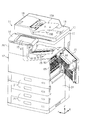
次に図3〜図7を参照して、給送機構部35における媒体検出装置80の周辺を含む部分の構成について説明する。なお、図5及び図6はカバー23を閉じた状態、図7はカバー23を開けた状態を示す。 Next, with reference to FIGS. 3 to 7, the configuration of the portion of the feeding mechanism portion 35 including the periphery of the medium detection device 80 will be described. 5 and 6 show a state in which the cover 23 is closed, and FIG. 7 shows a state in which the cover 23 is opened.

図3及び図4に示すように、印刷装置11の装置本体20に対して開閉可能なカバー23を開くと、各給送部41〜43の一部が露出する。各給送部41〜43は、本体20内の不図示のフレームに組み付けられた本体側給送機構部65と、カバー23の内面側に組み付けられたカバー側給送機構部66とにより構成される。本体20側には媒体検出装置80が組み付けられている。媒体検出装置80は、給送又は搬送中の媒体Pをその上面で支持しつつ、その上面の窓部88を通して媒体Pを幅方向Xに読み取って媒体Pの側端を検出する。このため、媒体検出装置80の媒体Pを支持する上面部分をなす媒体案内部81A及び媒体支持部81Bも、本体側給送機構部65の一部を構成している。 As shown in FIGS. 3 and 4, when the cover 23 that can be opened and closed is opened with respect to the apparatus body 20 of the printing apparatus 11, a part of each of the feeding units 41 to 43 is exposed. Each of the feeding units 41 to 43 is composed of a main body side feeding mechanism unit 65 assembled to a frame (not shown) in the main body 20, and a cover side feeding mechanism unit 66 assembled to the inner surface side of the cover 23. It A medium detection device 80 is assembled on the main body 20 side. The medium detection device 80 detects the side edge of the medium P by reading the medium P in the width direction X through the window 88 on the upper surface while supporting the medium P being fed or conveyed by the upper surface thereof. Therefore, the medium guiding portion 81A and the medium supporting portion 81B, which are the upper surface portion that supports the medium P of the medium detecting device 80, also form part of the main body side feeding mechanism portion 65.

図5及び図7に示すように、本体側給送機構部65には、第2給送部42を構成する分離ローラー対50、駆動ローラー51A、ガイド部材67、第3給送部43を構成する駆動ローラー57A、ガイド部材68,69及び搬送ローラー対46等が含まれる。また、媒体検出装置80は、その筐体81の上面部における搬送方向Yの上流側部分に第2給送路48からの媒体Pを案内する斜状の媒体案内部81Aを有している。さらに媒体検出装置80は、筐体81における媒体案内部81Aに対して搬送方向Yの下流側となる上面部分に、第1給送路45及び第2給送路48からの媒体Pを支持する媒体支持部81Bを有している。このため、これらの媒体案内部81A及び媒体支持部81Bは、本体側給送機構部65の一部を構成している。 As shown in FIGS. 5 and 7, in the main body side feeding mechanism portion 65, a separation roller pair 50 that constitutes the second feeding portion 42, a drive roller 51A, a guide member 67, and a third feeding portion 43 are configured. The drive roller 57A, the guide members 68 and 69, the transport roller pair 46, and the like are included. Further, the medium detecting device 80 has an oblique medium guiding portion 81A that guides the medium P from the second feeding path 48 at the upstream side portion in the transport direction Y on the upper surface portion of the housing 81. Further, the medium detecting device 80 supports the medium P from the first feeding path 45 and the second feeding path 48 on the upper surface portion of the housing 81, which is on the downstream side in the transport direction Y with respect to the medium guiding portion 81A. It has a medium support portion 81B. Therefore, the medium guiding portion 81A and the medium supporting portion 81B constitute a part of the main body side feeding mechanism portion 65.

また、図5及び図7に示すように、カバー側給送機構部66には、第1給送部41を構成する給送ローラー対44、ガイド部材70,71、第2給送部42を構成する従動ローラー51B,52、ガイド部材72及び第3給送部43を構成する従動ローラー57Bが含まれる。カバー23と一体に組み付けられているガイド部材71は、第1給送路45を構成する媒体案内面71Aと、反転給送路56を構成する媒体案内面71Bとを有する。カバー側給送機構部66には、複数の媒体載置部の一例を構成する給送トレイ22及びカセット21のうち少なくとも1つから媒体Pを給送する給送機構が含まれる。本例では、複数の媒体載置部の一例は、給送トレイ22及びカセット21の両方であり、カバー23には、給送部の少なくとも一部の一例として、第1給送部41の全部及び第2給送部42の一部が組み付けられている。 Further, as shown in FIGS. 5 and 7, the cover-side feeding mechanism portion 66 includes the feeding roller pair 44, the guide members 70 and 71, and the second feeding portion 42 that form the first feeding portion 41. The driven rollers 51B and 52, the guide member 72, and the driven roller 57B that configures the third feeding unit 43 are included. The guide member 71, which is integrally assembled with the cover 23, has a medium guiding surface 71A that constitutes the first feeding path 45 and a medium guiding surface 71B that constitutes the reversing feeding path 56. The cover-side feeding mechanism unit 66 includes a feeding mechanism that feeds the medium P from at least one of the feeding tray 22 and the cassette 21 that form an example of the plurality of medium placement units. In the present example, an example of the plurality of medium loading units is both the feeding tray 22 and the cassette 21, and the cover 23 includes the entire first feeding unit 41 as an example of at least a part of the feeding unit. And a part of the second feeding unit 42 is assembled.

図5及び図6に示すように、給送ローラー対44は、駆動ローラー44Aと従動ローラー44Bとを備える。両ローラー44A,44Bの給送方向の下流側には、ガイド部材70と、ガイド部材71の媒体案内面71Aとが対向して配置されることで、第1給送路45の一部が形成されている。また、互いに対向するガイド部材67,72、及び媒体検出装置80の媒体案内部81Aにより、第2給送路48の一部が形成されている。 As shown in FIGS. 5 and 6, the feeding roller pair 44 includes a driving roller 44A and a driven roller 44B. The guide member 70 and the medium guiding surface 71A of the guide member 71 are arranged to face each other on the downstream side of the rollers 44A and 44B in the feeding direction, so that a part of the first feeding path 45 is formed. Has been done. Further, the guide members 67 and 72 facing each other and the medium guiding portion 81A of the medium detecting device 80 form a part of the second feeding path 48.

図5に示すように、第2給送部42を構成する分離ローラー対50は、駆動ローラー50Aと従動ローラー50Bとからなる。
また、図5及び図6に示すように、第3給送部43を構成する反転搬送ローラー対57は、駆動ローラー57Aと従動ローラー57Bとからなる。片面が印刷済みの媒体Pを反転させて給送する反転給送路56の下流側の部分は、対向して配置された本体20側のガイド部材68とカバー23側のガイド部材71とにより形成されている。また、媒体検出装置80のうちガイド部材68と対向する面も反転給送路56の一部を形成している。また、媒体検出装置80の搬送方向Yの下流側の位置に配置された搬送ローラー対46は、駆動ローラー46Aと従動ローラー46Bとからなる。
As shown in FIG. 5, the separation roller pair 50 forming the second feeding unit 42 includes a driving roller 50A and a driven roller 50B.
Further, as shown in FIGS. 5 and 6, the reversal conveyance roller pair 57 that constitutes the third feeding unit 43 includes a drive roller 57A and a driven roller 57B. The downstream side portion of the reverse feeding path 56 that reverses and feeds the medium P having one surface printed is formed by the guide member 68 on the main body 20 side and the guide member 71 on the cover 23 side that are arranged to face each other. Has been done. The surface of the medium detecting device 80 facing the guide member 68 also forms a part of the reverse feeding path 56. The pair of transport rollers 46 arranged at the downstream side of the medium detection device 80 in the transport direction Y includes a drive roller 46A and a driven roller 46B.

図5に示す駆動ローラー44Aは、第1給送モーター121(図16参照)の動力により駆動される。また、駆動ローラー50A,51Aは、第2給送モーター122(図16参照)の動力により駆動される。また、駆動ローラー46A及び駆動ローラー57Aは、第1搬送モーター123(図16参照)の動力により駆動される。なお、図2に示すベルト搬送機構58は、ベルト用モーター124(図16参照)の動力により駆動される。また、図2に示す排出機構部38は、第2搬送モーター125(図16参照)の動力により駆動される。 The drive roller 44A shown in FIG. 5 is driven by the power of the first feeding motor 121 (see FIG. 16). The drive rollers 50A and 51A are driven by the power of the second feeding motor 122 (see FIG. 16). The drive roller 46A and the drive roller 57A are driven by the power of the first transport motor 123 (see FIG. 16). The belt transport mechanism 58 shown in FIG. 2 is driven by the power of the belt motor 124 (see FIG. 16). Further, the ejection mechanism unit 38 shown in FIG. 2 is driven by the power of the second transport motor 125 (see FIG. 16).

図6に示すように、第1給送路45と第2給送路48とは第1合流部75で合流している。この第1合流部75よりも給送方向(搬送方向Y)の下流側では、搬送通路の一例としての第2給送路48と両面印刷通路の一例としての反転給送路56とが通路合流部の一例としての第2合流部76で合流している。つまり、第1合流部75及び第2合流部76の間は、給送トレイ22から給送された媒体Pと、カセット21から給送された媒体Pとの共通の給送路である第1共通給送路77となっている。そして、第2合流部76よりも給送方向(搬送方向Y)の下流側は、媒体Pの一方の面を印刷するために給送される印刷前の媒体Pと、両面印刷を行うために一方の面が印刷された後に他方の面に印刷するために再給送される印刷後の媒体Pとの共通の給送路である第2共通給送路78となっている。このように印刷ヘッド34(図2参照)よりも搬送方向Yの上流側には、片面印刷経路の一例を構成する第1給送路45、第2給送路48及び第1共通給送路77と、反転給送路56との合流部である第2合流部76が存在している。 As shown in FIG. 6, the first feeding path 45 and the second feeding path 48 join at a first joining portion 75. On the downstream side of the first merging portion 75 in the feeding direction (conveying direction Y), the second feeding path 48 as an example of the conveying path and the reverse feeding path 56 as an example of the double-sided printing path are joined. The second merging portion 76 is an example of the merging portion. In other words, a space between the first merging portion 75 and the second merging portion 76 is a common feeding path for the medium P fed from the feeding tray 22 and the medium P fed from the cassette 21. It is a common feeding path 77. The downstream side of the second merging unit 76 in the feeding direction (conveying direction Y) is for performing double-sided printing with the pre-printing medium P that is fed to print one surface of the medium P. The second common feeding path 78 is a common feeding path with the printed medium P that is re-fed for printing on the other surface after printing on one surface. Thus, on the upstream side of the print head 34 (see FIG. 2) in the transport direction Y, the first feeding path 45, the second feeding path 48, and the first common feeding path that form an example of the single-sided printing path. There is a second merging portion 76 which is a merging portion between 77 and the reverse feeding path 56.

図6に示すように、第2合流部76を形成する複数の媒体案内面は、ガイド部材71の2つの媒体案内面71A,71Bの下流側の部分、反転給送路56を形成している媒体案内面68Aの下流側部分及び媒体検出装置80の媒体支持部81Bの少し下流寄り部分の表面である。これらの面によって媒体Pが合流する部分(合流領域)が形成される。カバー23(図5及び図7を参照)に組み付けられているガイド部材71は、第2合流部76を形成している一部の媒体案内面71A,71Bを有している。特にガイド部材71の2つの媒体案内面71A,71Bが交差する箇所によって第2合流部76が形成されている。 As shown in FIG. 6, the plurality of medium guiding surfaces forming the second merging portion 76 form a portion of the guide member 71 on the downstream side of the two medium guiding surfaces 71</b>A and 71</b>B, and the reverse feeding path 56. They are the surface of the downstream side portion of the medium guiding surface 68A and the surface of the medium supporting portion 81B of the medium detecting device 80 slightly downstream. These surfaces form a portion where the media P merge (merge area). The guide member 71 assembled to the cover 23 (see FIGS. 5 and 7) has a part of the medium guiding surfaces 71A and 71B forming the second joining portion 76. In particular, the second merging portion 76 is formed by the location where the two medium guiding surfaces 71A and 71B of the guide member 71 intersect.

図5及び図6に示すように、媒体検出装置80は、第1合流部75及び第2合流部76の下側に配置されている。媒体検出装置80の筐体81の上面部は、第2給送路48、第1共通給送路77及び第2共通給送路78の一部を構成している。また、搬送ローラー対46に対して搬送方向Yの上流側には、媒体Pの搬送方向Yの端部を検出可能なセンサー79が設けられている。このセンサー79は、媒体Pの搬送方向Yの先端を検知して、搬送ローラー対46による媒体Pのスキュー取り動作のタイミングを決めるために用いられる。 As shown in FIGS. 5 and 6, the medium detection device 80 is arranged below the first merging portion 75 and the second merging portion 76. The upper surface of the housing 81 of the medium detecting device 80 constitutes a part of the second feeding path 48, the first common feeding path 77, and the second common feeding path 78. Further, a sensor 79 capable of detecting the end portion of the medium P in the transport direction Y is provided on the upstream side of the transport roller pair 46 in the transport direction Y. The sensor 79 is used to detect the leading end of the medium P in the transport direction Y and determine the timing of the skew removal operation of the medium P by the transport roller pair 46.

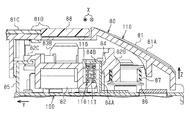
図6に示すように、媒体検出装置80は、前述の筐体81と、筐体81内に幅方向X(図6では紙面直交方向)に移動可能に収容されたキャリッジ82と、キャリッジ82における搬送経路30と対向する側に設けられたセンサー83と、キャリッジ82を移動させる動力源の一例としての電動モーター103(図12、図16を参照)とを備えている。筐体81内には、キャリッジ82を幅方向Xに沿って移動可能に案内する一対のレール部84,85が設けられている。キャリッジ82は、複数のプーリー86(図6では1つのみ示す)に巻き掛けられた無端状のベルト87の一部に固定されている。媒体検出装置80は、電動モーター103の動力によるベルト87の回転によってキャリッジ82を幅方向Xに往復移動させるベルト駆動方式を採用する。このように印刷ヘッド34とは別体に媒体検出装置80を設けているので、キャリッジ82及びセンサー83は印刷ヘッド34(図2参照)と独立して幅方向Xに移動可能である。 As shown in FIG. 6, the medium detection device 80 includes a housing 81, a carriage 82 housed in the housing 81 so as to be movable in the width direction X (a direction orthogonal to the paper surface of FIG. 6), and a carriage 82. A sensor 83 provided on the side facing the transport path 30 and an electric motor 103 (see FIGS. 12 and 16) as an example of a power source for moving the carriage 82 are provided. Inside the housing 81, a pair of rail portions 84 and 85 for guiding the carriage 82 so as to be movable along the width direction X are provided. The carriage 82 is fixed to a part of an endless belt 87 wound around a plurality of pulleys 86 (only one is shown in FIG. 6). The medium detection device 80 adopts a belt drive system in which the carriage 82 is reciprocated in the width direction X by the rotation of the belt 87 by the power of the electric motor 103. Since the medium detection device 80 is provided separately from the print head 34 in this way, the carriage 82 and the sensor 83 can move in the width direction X independently of the print head 34 (see FIG. 2).

図6に示すように、媒体検出装置80の筐体81には、キャリッジ82が移動するときにセンサー83の検出方向側に対向する部分に光透過部材からなる窓部88が設けられている。窓部88を構成する光透過部材は、例えば透明なガラス又は透明プラスチック等の透明部材からなる。本例のセンサー83は光学式センサーであり、第1共通給送路77を給送される媒体Pを、窓部88を介して光学的に読み取ることで媒体Pの幅方向Xの側端を検出する。キャリッジ82は、印刷ヘッド34よりも搬送方向Yの上流側の位置で幅方向Xに移動可能である。そのため、センサー83は、印刷ヘッド34よりも搬送方向Yの上流側の位置で媒体Pの側端を検出可能である。よって、媒体検出装置80が予め検出した媒体Pの側端位置を、それよりも下流側の位置で印刷を行う印刷ヘッド34の制御に使用できる。 As shown in FIG. 6, the housing 81 of the medium detecting device 80 is provided with a window portion 88 made of a light transmitting member at a portion facing the detection direction side of the sensor 83 when the carriage 82 moves. The light transmitting member forming the window portion 88 is made of a transparent member such as transparent glass or transparent plastic. The sensor 83 of this example is an optical sensor, and the medium P fed through the first common feeding path 77 is optically read through the window portion 88 to detect the side end of the medium P in the width direction X. To detect. The carriage 82 is movable in the width direction X at a position upstream of the print head 34 in the transport direction Y. Therefore, the sensor 83 can detect the side edge of the medium P at a position upstream of the print head 34 in the transport direction Y. Therefore, the side edge position of the medium P detected by the medium detection device 80 in advance can be used for controlling the print head 34 that performs printing at a position downstream thereof.

図6に示すように、センサー83がその検出方向(光出射方向)に窓部88を介して対向する領域、つまり読取位置に対応する対向領域には、ガイド部材71の媒体案内面71Aの一部が搬送方向Yに窓部88と平行かつ幅方向Xにセンサー83の移動経路と平行な状態で水平に延びている。つまり、媒体案内面71Aのその一部は、センサー83の移動経路上のどの位置にあってもセンサー83と等距離を維持可能な水平面となっている。そして、媒体案内面71Aの水平部分のうち少なくともセンサー83の移動経路と対向する領域は、センサー83からの光を反射する光反射面71Cとなっている。本例のガイド部材71は金属製で、光反射面71Cは、ガイド部材71の媒体案内面71Aのうち対応する部分を、例えば研磨又はめっき等により鏡面に加工されている。 As shown in FIG. 6, in a region where the sensor 83 faces the detection direction (light emission direction) through the window 88, that is, in a facing region corresponding to the reading position, one of the medium guiding surfaces 71A of the guide member 71 is provided. The section extends horizontally in the transport direction Y in parallel with the window 88 and in the width direction X in parallel with the movement path of the sensor 83. That is, a part of the medium guiding surface 71A is a horizontal plane that can maintain the same distance as the sensor 83 regardless of the position on the moving path of the sensor 83. Then, at least a region of the horizontal portion of the medium guiding surface 71A facing the movement path of the sensor 83 is a light reflecting surface 71C that reflects the light from the sensor 83. The guide member 71 of this example is made of metal, and the light reflecting surface 71C is a mirror-finished portion of the corresponding portion of the medium guiding surface 71A of the guide member 71, for example, by polishing or plating.

光反射面71Cは媒体Pよりも光反射率が十分高く形成されており、光反射型のセンサー83は、光反射面71Cからの反射光を受光してその受光量に応じた検出電圧値が閾値を超える場合にLレベルを出力し、媒体Pからの反射光を受光してその受光量に応じた検出電圧値が閾値以下である場合にHレベルを出力する(図18、図19を参照)。つまり、センサー83は、媒体Pを検知していないときにLレベルを出力し、媒体Pを検知した場合にHレベルを出力する。なお、センサー83が媒体Pの有無に応じた検出信号を出力可能であればよく、例えば光反射面71Cに塗装又は粗面加工を施すことにより、光反射面71Cを媒体Pよりも十分低反射率の面としてもよい。 The light reflection surface 71C is formed with a light reflectance sufficiently higher than that of the medium P, and the light reflection type sensor 83 receives the reflected light from the light reflection surface 71C and has a detected voltage value according to the received light amount. If the threshold value is exceeded, the L level is output, and the reflected light from the medium P is received, and if the detected voltage value according to the received light amount is less than or equal to the threshold value, the H level is output (see FIGS. 18 and 19). ). That is, the sensor 83 outputs the L level when the medium P is not detected, and outputs the H level when the medium P is detected. It is sufficient that the sensor 83 can output a detection signal according to the presence/absence of the medium P. For example, by coating or roughening the light reflecting surface 71C, the light reflecting surface 71C has a sufficiently lower reflection than the medium P. It may be a rate aspect.

図6に示すように、媒体検出装置80の筐体81の上面部における斜状の媒体案内部81Aによって第2給送路48の一部が形成されている。また、筐体81の上面部のうち窓部88と窓部88に対して搬送方向Yの下流側に位置する媒体案内部81Cとにより、給送トレイ22及びカセット21から給送される媒体Pが共通に支持される媒体支持部81Bが構成されている。媒体検出装置80は、筐体81の上部から搬送方向Yの下流側へ延出する延出部81Dを有する。この延出部81Dは従動ローラー46Bを支持する支持部材の一部からなるガイド部材69と対向する位置に配置され、第2共通給送路78の一部を形成している。 As shown in FIG. 6, a part of the second feeding path 48 is formed by the oblique medium guiding portion 81A on the upper surface of the housing 81 of the medium detecting device 80. Further, the medium P fed from the feeding tray 22 and the cassette 21 by the window portion 88 and the medium guiding portion 81C located on the downstream side of the window portion 88 in the transport direction Y on the upper surface portion of the housing 81. A medium support portion 81B is commonly supported. The medium detection device 80 has an extension part 81D extending from the upper part of the housing 81 to the downstream side in the transport direction Y. The extending portion 81D is arranged at a position facing the guide member 69 formed of a part of a supporting member that supports the driven roller 46B, and forms a part of the second common feeding path 78.

図6に示すように、キャリッジ82は、搬送ユニット32により搬送される媒体Pの搬送経路30に対して印刷ヘッド34側とは反対側の位置で幅方向Xに移動可能に設けられている。センサー83は、搬送経路30を挟んで印刷ヘッド34側とは反対側の位置から媒体Pに向かって光を照射することで、媒体Pの側端を検出可能である。 As shown in FIG. 6, the carriage 82 is provided so as to be movable in the width direction X at a position opposite to the print head 34 side with respect to the transport path 30 of the medium P transported by the transport unit 32. The sensor 83 can detect the side edge of the medium P by irradiating the medium P with light from a position opposite to the print head 34 side with the transport path 30 in between.

図6に示すように、媒体検出装置80は、センサー83の読取位置(図6では破線位置)が、第1共通給送路77と反転給送路56とが合流する第2合流部76よりも搬送方向Yの上流側となる位置に配置されている。例えば一方の面が印刷された媒体Pを読み取り可能な位置に媒体検出装置80を配置しようとすると、第2合流部76を媒体検出装置80の読取位置よりも搬送方向の上流側へずらして配置する必要があり、それに伴い、反転給送路56を有する第3給送部43及び第1給送部41を、搬送方向Yの上流側へずらして配置する必要が生じる。この場合、印刷装置11の給送機構部35を搬送方向Yの上流側へ後退させた位置に配置する必要があり、その後退させた分だけ、印刷装置11の搬送方向Yのサイズ寸法が相対的に長くなり、印刷装置11が搬送方向Yに大型化する。 As shown in FIG. 6, in the medium detection device 80, the reading position (broken line position in FIG. 6) of the sensor 83 is from the second joining portion 76 where the first common feed path 77 and the reverse feed path 56 join. Is also arranged at a position on the upstream side in the transport direction Y. For example, if the medium detection device 80 is to be placed at a position where the medium P having one surface printed thereon can be read, the second merging portion 76 is arranged so as to be shifted upstream of the reading position of the medium detection device 80 in the transport direction. Therefore, it is necessary to shift the third feeding section 43 and the first feeding section 41 having the reverse feeding path 56 to the upstream side in the transport direction Y. In this case, it is necessary to dispose the feeding mechanism portion 35 of the printing device 11 at a position retracted to the upstream side in the transport direction Y, and the size dimension of the printing device 11 in the transport direction Y is relative to the retracted position. The length of the printing apparatus 11 increases, and the printing apparatus 11 increases in size in the transport direction Y.

これに対して、一方の面が印刷された媒体Pの側端を読み取ることはせず、媒体検出装置80に対して第2経路合流部J2を読取位置よりも下流側となる位置に配置することで、第1給送部41及び第3給送部43を、搬送方向Yの上流側へずらして配置する必要がなくなる。このようにして印刷装置11の搬送方向Yのサイズ寸法を相対的に短くしている。 On the other hand, the side edge of the medium P on which one surface is printed is not read, and the second path merging portion J2 is arranged at a position downstream of the reading position with respect to the medium detection device 80. This eliminates the need to shift the first feeding unit 41 and the third feeding unit 43 to the upstream side in the transport direction Y. In this way, the size dimension of the printing device 11 in the transport direction Y is relatively shortened.

また、図6に示すように、給送ローラー対44の回転により給送される媒体Pの経路である第1給送経路91と、第2給送路48に沿って給送される媒体Pの経路である第2給送経路92とは、第1合流部75よりも少し下流側に位置する第1経路合流部J1で合流する。さらに第2給送経路92には、反転給送路56に沿って給送される媒体Pの経路である両面印刷経路の一例としての第3給送経路93が、第2合流部76よりも少し下流側に位置する合流部の一例としての第2経路合流部J2で合流する。媒体検出装置80の読取位置は、第2経路合流部J2よりも搬送方向Yの上流側に位置する。また、媒体検出装置80の読取位置は、第1経路合流部J1よりも搬送方向Yの下流側に位置する。この読取位置の位置範囲は、カセット21及び給送トレイ22から給送された各媒体Pが共通に搬送される共通搬送経路のうち、第2経路合流部J2よりも上流側の部分となっている。このため、どの給送元(媒体載置部)からの媒体Pであるかに関係なく、その媒体Pをセンサー83とほぼ一定の距離を保った状態で読み取って側端検出が可能であるうえ、反転給送路56を通って給送されてきた媒体Pの一方の面に施された印刷のインクが窓部88に付着することが回避され易い。よって、読取位置でのセンサー83と媒体Pとの距離のばらつき及び窓部88のインク汚れ等に起因する、媒体Pの側端の検出精度の低下や誤検出が低減される。 Further, as shown in FIG. 6, the medium P that is fed along the first feeding path 91 and the second feeding path 48 that are the paths of the medium P that is fed by the rotation of the feeding roller pair 44. The second feeding path 92, which is the path of (1), joins at the first path joining section J1 located slightly downstream of the first joining section 75. Furthermore, in the second feeding path 92, a third feeding path 93, which is an example of a double-sided printing path that is a path of the medium P fed along the reverse feeding path 56, is provided more than in the second joining section 76. Merging is performed at the second passage merging portion J2, which is an example of the merging portion located slightly downstream. The reading position of the medium detection device 80 is located on the upstream side in the transport direction Y with respect to the second path merging portion J2. The reading position of the medium detection device 80 is located on the downstream side in the transport direction Y with respect to the first path junction J1. The position range of the reading position is a portion on the upstream side of the second path merging section J2 in the common transport path on which the respective media P fed from the cassette 21 and the feed tray 22 are commonly transported. There is. Therefore, regardless of which feeding source (medium placing portion) the medium P is, the side edge can be detected by reading the medium P while keeping a substantially constant distance from the sensor 83. It is easy to avoid that the printing ink applied to one surface of the medium P that has been fed through the reverse feeding path 56 adheres to the window 88. Therefore, the lowering of the detection accuracy of the side edge of the medium P and the erroneous detection due to the variation in the distance between the sensor 83 and the medium P at the reading position, the ink stain on the window 88, and the like are reduced.

なお、本実施形態では、媒体検出装置80の読取位置は、第2経路合流部J2よりも搬送方向Yの上流側であればよい。また、読取位置は、第2合流部76よりも搬送方向Yの上流側であることが好ましい。さらに、媒体検出装置80の読取位置は、第1合流部75よりも搬送方向Yの下流側であればよい。また、読取位置は、第1経路合流部J1よりも搬送方向Yの下流側であることが好ましい。 In the present embodiment, the reading position of the medium detection device 80 may be on the upstream side in the transport direction Y with respect to the second path merging portion J2. Further, the reading position is preferably on the upstream side in the transport direction Y with respect to the second joining section 76. Further, the reading position of the medium detection device 80 may be on the downstream side in the transport direction Y with respect to the first merging portion 75. Further, the reading position is preferably on the downstream side in the transport direction Y with respect to the first path merging portion J1.

また、読取位置が、第2合流部76よりも上流側となる位置にあれば、第2合流部76を形成する2つの媒体案内面71A,71Bをもつガイド部材71が、センサー83の移動経路と対向して位置する。そして、本例では、ガイド部材71におけるセンサー83と対向する領域に、センサー83からの光を反射させる光反射面71Cを形成し、媒体案内用の部材と光反射面用の部材との共通化が図られている。 Further, if the reading position is located on the upstream side of the second merging portion 76, the guide member 71 having the two medium guiding surfaces 71A and 71B forming the second merging portion 76 is moved by the movement path of the sensor 83. Located opposite to. In this example, a light reflecting surface 71C that reflects the light from the sensor 83 is formed in a region of the guide member 71 facing the sensor 83, and the medium guiding member and the light reflecting surface member are used in common. Is being pursued.

図7に示すように、カバー23を開けると、ガイド部材71及びガイド部材72等を含むカバー側給送機構部66がカバー23と共に退避方向(搬送方向Yの上流側)へ移動し、媒体検出装置80が露出する。すなわち、媒体検出装置80は、その読取位置が第2経路合流部J2よりも搬送方向Yの上流側に位置する配置なので、第2合流部76を形成するガイド部材71が後方へ退避すると、図7及び図8に示すように露出するようになっている。特に読取位置が第2合流部76よりも搬送方向Yの上流側に位置する配置なので、第2合流部76を形成するガイド部材71が後方へ退避すると、図7及び図8に示すように窓部88も露出するようになっている。例えば窓部88の表面の汚れを除去する清掃は、媒体検出装置80を本体20に組み付けたまま行うことが可能である。 As shown in FIG. 7, when the cover 23 is opened, the cover side feeding mechanism unit 66 including the guide member 71 and the guide member 72 and the like moves together with the cover 23 in the retreat direction (the upstream side in the transport direction Y) to detect the medium. The device 80 is exposed. That is, the medium detection device 80 is arranged such that its reading position is located on the upstream side in the transport direction Y with respect to the second path merging portion J2. Therefore, when the guide member 71 forming the second merging portion 76 is retracted rearward, 7 and 8 are exposed. In particular, since the reading position is located on the upstream side in the transport direction Y with respect to the second merging portion 76, when the guide member 71 forming the second merging portion 76 is retracted rearward, as shown in FIG. 7 and FIG. The portion 88 is also exposed. For example, the cleaning for removing the dirt on the surface of the window portion 88 can be performed with the medium detection device 80 attached to the main body 20.

次に、図8〜図15を参照して媒体検出装置80の詳細な構成を説明する。
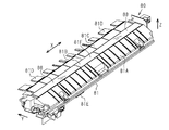
図8に示すように、媒体検出装置80は、幅方向Xに最大幅の媒体Pの幅よりも少し長く延びた長尺形状を有している。窓部88は幅方向X(筐体長手方向)に沿って2つ設けられている。本実施形態の印刷装置11では、媒体Pはサイズに依らずその幅中心が給送路の幅中心位置を通るセンター給送が行われる。2つの窓部88と媒体案内部81Cとによって媒体支持部81Bが形成されている。また、媒体検出装置80は筐体81の下部にコネクター81Eを有している。このコネクター81Eには制御部120からの配線に接続された不図示のコネクターが接続され、センサー83の検出信号はコネクター81E及び不図示の配線を介して制御部120に入力される。
Next, a detailed configuration of the medium detection device 80 will be described with reference to FIGS.
As shown in FIG. 8, the medium detection device 80 has an elongated shape that extends in the width direction X slightly longer than the width of the medium P having the maximum width. Two window portions 88 are provided along the width direction X (longitudinal direction of the housing). In the printing apparatus 11 according to the present embodiment, the medium P is fed by the center, whose width center passes through the width center position of the feeding path regardless of the size. The medium support portion 81B is formed by the two windows 88 and the medium guide portion 81C. The medium detection device 80 also has a connector 81E at the bottom of the housing 81. A connector (not shown) connected to the wiring from the control unit 120 is connected to the connector 81E, and the detection signal of the sensor 83 is input to the control unit 120 via the connector 81E and the wiring (not shown).

図9に示すように、媒体検出装置80の上面は、媒体案内部81A、2つの窓部88、2つの窓部88の間に介在する支持部81F、媒体案内部81C及び延出部81Dを備える。カセット21から給送された媒体Pは、媒体案内部81Aにより案内される。また、カセット21から給送された媒体P、及び給送トレイ22から給送された媒体Pは、窓部88、支持部81F及び媒体案内部81Cの上面からなる支持面に案内される。延出部81Dは、櫛歯状に複数延出しており、それぞれが幅方向Xに複数設けられた搬送ローラー対46間の間隙に挿入されている。搬送ローラー対46へ挿入される際の媒体Pは、複数の延出部81Dの上面によって支持される。 As shown in FIG. 9, the upper surface of the medium detecting device 80 includes a medium guiding portion 81A, two window portions 88, a support portion 81F interposed between the two window portions 88, a medium guiding portion 81C, and an extending portion 81D. Prepare The medium P fed from the cassette 21 is guided by the medium guiding portion 81A. Further, the medium P fed from the cassette 21 and the medium P fed from the feeding tray 22 are guided to the support surface including the window 88, the support 81F, and the medium guide 81C. The plurality of extending portions 81D extend in a comb-like shape, and are inserted in the gaps between the pair of transport rollers 46 provided in the width direction X, respectively. The medium P when being inserted into the pair of transport rollers 46 is supported by the upper surfaces of the plurality of extending portions 81D.

図10に示すように、媒体検出装置80の筐体81は、基台100とカバー110とより構成される。基台100の上面には、一対のレール部84,85が長手方向に沿って互いに平行に延びるように設けられている。キャリッジ82は、一対のレール部84,85に沿って筐体81の長手方向に移動可能に組み付けられている。また、基台100の上面には、基台100の長手方向の両端部に相当する各位置に、一対のプーリー86が長手方向に所定の間隔を離した状態で組み付けられている。一対のプーリー86には無端状のベルト87が巻き掛けられており、ベルト87の一部にキャリッジ82が固定されている。キャリッジ82に設けられたセンサー83は、筐体81の長手方向(幅方向X)に異なる位置に配置された一対のセンサー83A,83Bよりなる。また、キャリッジ82と基台100の上面における長手方向中央部との間は、フレキシブルフラットケーブル89を介して接続されている。また、基台100の上面における長手方向端部には、キャリッジ82が、その幅方向Xに沿った移動経路の端部に位置するホーム位置(ホームポジション)にあることを検知する位置センサー90が設けられている。なお、以下の説明では、センサー83Aを第1センサー83A、センサー83Bを第2センサー83Bと称する場合もある。 As shown in FIG. 10, the housing 81 of the medium detection device 80 includes a base 100 and a cover 110. A pair of rail portions 84 and 85 are provided on the upper surface of the base 100 so as to extend parallel to each other along the longitudinal direction. The carriage 82 is attached so as to be movable in the longitudinal direction of the housing 81 along the pair of rail portions 84 and 85. Further, on the upper surface of the base 100, a pair of pulleys 86 are assembled at respective positions corresponding to both ends of the base 100 in the longitudinal direction with a predetermined gap in the longitudinal direction. An endless belt 87 is wound around the pair of pulleys 86, and the carriage 82 is fixed to a part of the belt 87. The sensor 83 provided on the carriage 82 includes a pair of sensors 83A and 83B arranged at different positions in the longitudinal direction (width direction X) of the housing 81. Further, a flexible flat cable 89 is connected between the carriage 82 and the central portion in the longitudinal direction on the upper surface of the base 100. A position sensor 90 that detects that the carriage 82 is at the home position (home position) located at the end of the movement path along the width direction X is provided at the longitudinal end portion on the upper surface of the base 100. It is provided. In the following description, the sensor 83A may be referred to as the first sensor 83A and the sensor 83B may be referred to as the second sensor 83B.

図10に示すように、基台100にはその周縁部に周方向に適度な間隔を開けて複数のネジ孔101が形成されている。カバー110の周縁部には、ネジ孔101と対応する位置に形成された不図示の複数のネジ挿通孔に挿通されたネジ111が、基台100側の対応するネジ孔101に螺着されることで、基台100とカバー110と一体に組み付けられ、筐体81が形成される。 As shown in FIG. 10, a plurality of screw holes 101 are formed in the base 100 at the peripheral edge thereof at appropriate intervals in the circumferential direction. On the peripheral edge of the cover 110, screws 111 inserted through a plurality of screw insertion holes (not shown) formed at positions corresponding to the screw holes 101 are screwed into the corresponding screw holes 101 on the base 100 side. As a result, the base 100 and the cover 110 are integrally assembled, and the housing 81 is formed.

図11に示すように、キャリッジ82は、同図に実線で示すホーム位置HPと、ホーム位置HPに対して幅方向Xの反対側の端部となる、同図に二点鎖線で示す反ホーム位置APとの間を移動可能となっている。フレキシブルフラットケーブル89の一端部は基台100の周縁部における長手方向中央部に固定されており、フレキシブルフラットケーブル89の固定箇所から延びる部分が一方のレール部85に沿って配線されると共に途中で円弧状に曲げられた後に他方のレール部84に沿って配線されて他端部がキャリッジ82に接続されている。そして、キャリッジ82の移動に伴ってフレキシブルフラットケーブル89はその円弧状になる部分が幅方向Xに移動することで、移動中のキャリッジ82と電気的な接続を維持する。 As shown in FIG. 11, the carriage 82 is a home position HP shown by a solid line in the figure and an end portion on the side opposite to the home position HP in the width direction X. It is movable to and from the position AP. One end of the flexible flat cable 89 is fixed to the central portion in the longitudinal direction of the peripheral portion of the base 100, and the portion extending from the fixed portion of the flexible flat cable 89 is wired along one rail portion 85 and at the middle thereof. After being bent in an arc shape, it is wired along the other rail portion 84 and the other end portion is connected to the carriage 82. With the movement of the carriage 82, the arc-shaped portion of the flexible flat cable 89 moves in the width direction X, thereby maintaining electrical connection with the moving carriage 82.

図11に示すように、キャリッジ82のホーム位置HPと反ホーム位置APとが、キャリッジ82が幅方向Xに移動するときの両側のエンド位置になっている。位置センサー90は、キャリッジ82がホーム位置HPにあるときにオンし、キャリッジ82がホーム位置HPから離れた位置にあるときにオフする。 As shown in FIG. 11, the home position HP and the anti-home position AP of the carriage 82 are end positions on both sides when the carriage 82 moves in the width direction X. The position sensor 90 turns on when the carriage 82 is at the home position HP, and turns off when the carriage 82 is at a position away from the home position HP.

図12に示すように、基台100の裏面には、電動モーター103が組み付けられている。電動モーター103の駆動軸は一方のプーリー86(図11における左側のプーリー86)に連結されている。本例の電動モーター103は、ステッピングモーターからなる。電動モーター103から延びる配線の先端にはコネクター104が接続されている。このコネクター104には制御部120から延びる配線に接続された不図示のコネクターが接続され、制御部120から電力及び制御信号が配線を通じて電動モーター103に入力される。制御部120からの制御信号(ステップ制御信号)に基づいて電動モーター103が正逆転駆動されることで、キャリッジ82はベルト87の正逆回転により幅方向Xに往復移動する。 As shown in FIG. 12, an electric motor 103 is attached to the back surface of the base 100. The drive shaft of the electric motor 103 is connected to one pulley 86 (the left pulley 86 in FIG. 11). The electric motor 103 in this example is a stepping motor. A connector 104 is connected to the tip of the wiring extending from the electric motor 103. A connector (not shown) connected to a wiring extending from the control unit 120 is connected to the connector 104, and electric power and control signals are input from the control unit 120 to the electric motor 103 through the wiring. The electric motor 103 is driven in the forward/reverse direction based on a control signal (step control signal) from the control unit 120, so that the carriage 82 reciprocates in the width direction X by the forward/reverse rotation of the belt 87.

また、図12に示すように、基台100の裏面には、フレキシブルフラットケーブル89の配線が基台100の表面側(内面側)から裏面側へ延びて露出し、所定の経路で保持された状態で裏面上に配線されてコネクター81Eに接続されている。また、コネクター81Eには、位置センサー90から延びる配線105が基台100の表面側(内面側)から裏面側へ延びて露出し、その配線105が基台100の裏面上を所定の経路に保持された状態で配線されてコネクター81Eに接続されている。 Further, as shown in FIG. 12, on the back surface of the base 100, the wiring of the flexible flat cable 89 extends from the front surface side (inner surface side) of the base 100 to the back surface side, is exposed, and is held in a predetermined path. In this state, it is wired on the back surface and connected to the connector 81E. Further, in the connector 81E, the wiring 105 extending from the position sensor 90 is exposed by extending from the front surface side (inner surface side) of the base 100 to the back surface side, and the wiring 105 holds the back surface of the base 100 on a predetermined path. The wires are wired in the connected state and connected to the connector 81E.

図13に示すように、2つのセンサー83A,83Bは、発光部106と受光部107とを備えている。発光部106から射出された光が反射した反射光を受光部107が受光することで、センサー83A,83Bは受光量に応じた電圧レベルの検出信号を出力する。第1センサー83Aから延びる配線89Aは途中で一部折り曲げて畳み込んだ状態で、第2センサー83Bから延びる配線89Bと一つに接続されて1つのフレキシブルフラットケーブル89となっている。このフレキシブルフラットケーブル89はキャリッジ82に形成された配線孔に挿通されてキャリッジ82の裏面側へ延びた後、レール部84の内側面に沿って配線されている。 As shown in FIG. 13, the two sensors 83A and 83B include a light emitting unit 106 and a light receiving unit 107. When the light receiving unit 107 receives the reflected light that is the light emitted from the light emitting unit 106, the sensors 83A and 83B output a detection signal of a voltage level according to the amount of received light. The wiring 89A extending from the first sensor 83A is partially folded and folded in the middle to be connected to one wiring 89B extending from the second sensor 83B to form one flexible flat cable 89. The flexible flat cable 89 is inserted into a wiring hole formed in the carriage 82, extends to the back surface side of the carriage 82, and then is wired along the inner side surface of the rail portion 84.

また、図13に示すように、位置センサー90は発光部90Aと受光部90Bとを備えている。キャリッジ82は、ホーム位置HP側の側部から幅方向Xの外側へ突出する被検出部82Aを備える。キャリッジ82がホーム位置HPにあるときには、発光部90Aと受光部90Bとの間の凹所90Cに挿入された被検出部82Aが、発光部90Aから受光部90Bへの投光を遮断することで、位置センサー90は検知状態となる。一方、キャリッジ82がホーム位置HPから反ホーム位置AP側へ移動した状態では、被検出部82Aが凹所90Cから退避し、発光部90Aから受光部90Bへの投光を受光部90Bが受光することで、位置センサー90は非検知状態となる。 Further, as shown in FIG. 13, the position sensor 90 includes a light emitting unit 90A and a light receiving unit 90B. The carriage 82 includes a detected portion 82A that projects outward from the side portion on the home position HP side in the width direction X. When the carriage 82 is at the home position HP, the detected portion 82A inserted in the recess 90C between the light emitting portion 90A and the light receiving portion 90B blocks light emission from the light emitting portion 90A to the light receiving portion 90B. The position sensor 90 is in the detection state. On the other hand, when the carriage 82 moves from the home position HP to the side opposite to the home position AP, the detected portion 82A retracts from the recess 90C, and the light receiving portion 90B receives light emitted from the light emitting portion 90A to the light receiving portion 90B. As a result, the position sensor 90 is in the non-detection state.

図14に示すように、レール部84は、基台100に対して垂直に鉛直方向Zへ延びた垂立部84Aと、垂立部84Aの上端部から屈曲し水平に延びる支持部84Bとを有する。キャリッジ82には、押圧部材112が圧縮ばね113の付勢力に押されてレール部84の垂立部84Aに押し付けられてなる位置決め機構114が設けられている。この押圧部材112がレール部84の垂立部84Aに対して所定の付勢力で水平方向に押し付けられることで、キャリッジ82は搬送方向Yに位置決めされている。このため、キャリッジ82の搬送方向Yのがたつきが抑制される。 As shown in FIG. 14, the rail portion 84 includes an upright portion 84A that extends vertically in the vertical direction Z with respect to the base 100, and a support portion 84B that bends from the upper end of the upright portion 84A and extends horizontally. Have. The carriage 82 is provided with a positioning mechanism 114 in which the pressing member 112 is pressed by the biasing force of the compression spring 113 and pressed against the upright portion 84A of the rail portion 84. The carriage 82 is positioned in the transport direction Y by the pressing member 112 being pressed horizontally against the upright portion 84A of the rail portion 84 with a predetermined biasing force. Therefore, rattling of the carriage 82 in the transport direction Y is suppressed.

図15に示すように、キャリッジ82には、押圧部材116が圧縮ばね117の付勢力に押されてレール部84の支持部84Bに押し付けられてなる位置決め機構118を有している。この押圧部材116がレール部84の支持部84Bに所定の付勢力で押し付けられることで、キャリッジ82は鉛直方向Zに位置決めされている。このため、キャリッジ82の鉛直方向のがたつきが抑制される。また、キャリッジ82の搬送方向Yの上流側の側部に突設された把持部82Bにベルト87が把持された状態で、キャリッジ82はベルト87に固定されている。また、キャリッジ82から搬送方向Yの下流側へ延出する板状のガイド部82Cがレール部85の上面に案内されている。キャリッジ82は、2種類の位置決め機構114,118を介して搬送方向Yと鉛直方向Zに姿勢を保持した状態で、ベルト87の駆動によりレール部84,85に沿って幅方向Xに移動可能となっている。 As shown in FIG. 15, the carriage 82 has a positioning mechanism 118 in which the pressing member 116 is pressed by the urging force of the compression spring 117 and pressed against the support portion 84B of the rail portion 84. The carriage 82 is positioned in the vertical direction Z by pressing the pressing member 116 against the support portion 84B of the rail portion 84 with a predetermined biasing force. Therefore, rattling of the carriage 82 in the vertical direction is suppressed. Further, the carriage 82 is fixed to the belt 87 in a state in which the belt 87 is gripped by the grip portion 82</b>B provided on the side portion on the upstream side of the carriage 82 in the transport direction Y. In addition, a plate-shaped guide portion 82C extending from the carriage 82 to the downstream side in the transport direction Y is guided by the upper surface of the rail portion 85. The carriage 82 is movable in the width direction X along the rail portions 84 and 85 by driving the belt 87 while maintaining the posture in the transport direction Y and the vertical direction Z via the two types of positioning mechanisms 114 and 118. Is becoming

図2及び図6に示す搬送ローラー対46はレジストローラーであって、その下流側への媒体Pの搬送開始タイミングを決定する。停止中の搬送ローラー対46に、給送されてきた媒体Pの先端部を突き当てることで、媒体Pのスキュー(斜行)を除去又は低減させるスキュー取り動作を行わせる。このときスキュー取り動作で媒体Pが搬送ローラー対46に突き当てられているとき、媒体Pは停止しつつ面内で斜行角度分の回動をすることでスキューが取り除かれる。このスキュー取り動作の後、給送部41,42による媒体Pの後端部側を送り出す給送速度と、搬送ローラー対46の回転により媒体Pの先端部側を送り出す搬送速度を合わせることで、媒体Pは一定の搬送速度でベルト搬送機構58の搬送ベルト61上へ搬入される。 The conveyance roller pair 46 shown in FIGS. 2 and 6 is a registration roller, and determines the conveyance start timing of the medium P to the downstream side thereof. By causing the leading end portion of the fed medium P to abut against the stopped transport roller pair 46, a skew removing operation for removing or reducing skew (skew) of the medium P is performed. At this time, when the medium P is abutted against the transport roller pair 46 in the skew removing operation, the skew is removed by rotating the medium P in the plane by the skew angle while stopping. After the skew removal operation, the feeding speed of feeding the rear end side of the medium P by the feeding units 41 and 42 and the feeding speed of feeding the front end side of the medium P by the rotation of the feeding roller pair 46 are matched, The medium P is carried onto the conveyor belt 61 of the belt conveyor mechanism 58 at a constant conveyor speed.

図6に示すように、センサー83の読取位置は、搬送ローラー対46が媒体Pをニップ(挟持)するニップ箇所よりも搬送方向Yの上流側の位置に設定されている。媒体検出装置80は、スキュー取り後の媒体Pの幅方向Xの側端を検出する。媒体検出装置80は、スキュー取り後の停止中の媒体P又はスキュー取り後の搬送が開始された低速の媒体Pに対して側端を検出できる。このため、例えば搬送ローラー対46よりも搬送方向Yの下流側の位置で媒体検出装置が媒体Pの側端を検出する構成とした場合、スキュー取り後の媒体Pの側端を検出できるものの、ある程度の搬送速度に達した比較的高速な媒体Pが検出対象となる。このため、例えば媒体Pの両側端を検出する場合、一方の側端と他方の側端とを媒体Pの搬送方向Yに大きく異なる位置で検出することになる。この場合、媒体Pのスキューが僅かに残っていると、媒体Pの幅及び側端の検出精度が若干低下する。これに対して、センサー83の読取位置を、スキュー取り動作に使用される搬送ローラー対46のニップ箇所よりも搬送方向Yの上流側に設定した本実施形態によれば、センサー83の読取位置を搬送ローラー対46のニップ箇所よりも搬送方向Yの下流側に設定する場合に比べ、媒体Pの側端位置及び幅をより精度高く取得できる。なお、媒体Pの側端検出処理は、スキュー取り後のタイミング以外に媒体Pの搬送中においても行って、1枚の媒体Pの搬送方向Yに異なる複数箇所で側端検出を行ってもよい。 As shown in FIG. 6, the reading position of the sensor 83 is set to a position on the upstream side in the transport direction Y with respect to the nip position where the transport roller pair 46 nips (sandwiches) the medium P. The medium detection device 80 detects the side edge of the medium P after the skew removal in the width direction X. The medium detection device 80 can detect the side edge of the medium P that is stopped after the skew is removed or the medium P that has been transported after the skew is removed and at a low speed. Therefore, for example, when the medium detection device is configured to detect the side edge of the medium P at a position downstream of the conveyance roller pair 46 in the conveyance direction Y, the side edge of the medium P after skew removal can be detected, A relatively high-speed medium P that has reached a certain transport speed is a detection target. Therefore, for example, when detecting both side edges of the medium P, one side edge and the other side edge are detected at positions greatly different in the transport direction Y of the medium P. In this case, if the skew of the medium P is slightly left, the detection accuracy of the width and the side edge of the medium P is slightly lowered. On the other hand, according to the present embodiment in which the reading position of the sensor 83 is set to the upstream side in the carrying direction Y with respect to the nip portion of the carrying roller pair 46 used for the skew removing operation, the reading position of the sensor 83 is set. The side end position and width of the medium P can be acquired with higher accuracy than in the case where the position is set on the downstream side in the transport direction Y with respect to the nip portion of the transport roller pair 46. The side edge detection processing of the medium P may be performed during the transportation of the medium P other than the timing after the skew removal, and the side edge detection may be performed at a plurality of different positions in the transportation direction Y of one medium P. ..

次に図16を参照して印刷装置11の電気的構成を説明する。図16に示すように、印刷装置11は、印刷装置11を統括的に制御する制御部120と、媒体検出装置80、前述の操作パネル14、媒体Pを搬送する搬送ユニット32及び搬送中の媒体Pに印刷する印刷ヘッド34を備える。搬送ユニット32は、給送トレイ22にセットされた媒体Pを給送する第1給送部41の動力源となる第1給送モーター121、及びカセット21に収容された媒体Pを給送する第2給送部42の動力源である第2給送モーター122とを備える。また、搬送ユニット32は、給送された媒体Pを搬送する搬送ローラー対46及び排出機構部38等の動力源となる第1搬送モーター123、ベルト搬送機構58の動力源となるベルト用モーター124、一方の面が印刷された媒体Pを搬送する搬送ローラー対55及び反転搬送ローラー対57の動力源となる第2搬送モーター125を有している。制御部120には、搬送系のモーター数と同数個のモーター駆動回路126〜130を介して複数のモーター121〜125が電気的に接続されている。制御部120は、モーター駆動回路126〜130を介して各モーター121〜125を制御することで、媒体Pの給送、搬送、両面印刷時の反転及び排出を行う。なお、搬送ローラー対55を正転と逆転に切り換え可能な電磁クラッチを設け、搬送ローラー対55及び反転搬送ローラー対57の動力源を搬送ローラー対46と共通の第1搬送モーター123とし、第2搬送モーター125を廃止した構成でもよい。 Next, the electrical configuration of the printing apparatus 11 will be described with reference to FIG. As shown in FIG. 16, the printing apparatus 11 includes a control unit 120 that integrally controls the printing apparatus 11, the medium detection device 80, the operation panel 14, the transport unit 32 that transports the medium P, and the medium that is being transported. A print head 34 for printing on P is provided. The transport unit 32 feeds the first feeding motor 121, which is a power source of the first feeding unit 41 that feeds the medium P set in the feeding tray 22, and the medium P stored in the cassette 21. The second feeding motor 122, which is a power source of the second feeding unit 42, is provided. The transport unit 32 also includes a pair of transport rollers 46 that transport the fed medium P, a first transport motor 123 that serves as a power source for the discharge mechanism 38, and a belt motor 124 that serves as a power source for the belt transport mechanism 58. The second transport motor 125 serves as a power source for the transport roller pair 55 and the reverse transport roller pair 57 that transport the medium P having one surface printed. A plurality of motors 121 to 125 are electrically connected to the control unit 120 via the same number of motor drive circuits 126 to 130 as the number of motors in the transport system. The control unit 120 controls the motors 121 to 125 via the motor drive circuits 126 to 130 to feed, convey, and reverse and eject the medium P during double-sided printing. An electromagnetic clutch capable of switching the transport roller pair 55 between normal rotation and reverse rotation is provided, and the power source of the transport roller pair 55 and the reverse transport roller pair 57 is the first transport motor 123 common to the transport roller pair 46, and the second The configuration may be such that the transport motor 125 is eliminated.

また、制御部120には、印刷ヘッド34が電気的に接続されている。制御部120は、例えばホスト装置(図示略)から受信した印刷ジョブデータPD中の印刷画像データに基づき印刷ヘッド34を制御することで、搬送中の媒体Pのうち搬送ベルト61上の部分に印刷ヘッド34のノズルからインク滴を吐出して、媒体Pに印刷画像データに基づく画像等を印刷させる。また、制御部120には、操作パネル14を構成する操作部16及び表示部15が電気的に接続されている。制御部120は、操作部16から入力した操作信号に基づき、表示部15に表示されたメニューの中から選択された項目に応じた各種の設定情報や、印刷、スキャン及びコピー等を指示する指示情報を受け付ける。また、制御部120は、前述のメニュー及び故障発生時や異常発生時にその旨をユーザーに通知するメッセージなどを表示部15に表示させる。 The print head 34 is electrically connected to the control unit 120. The control unit 120 controls the print head 34 based on the print image data in the print job data PD received from the host device (not shown), for example, to print on the portion of the medium P being conveyed on the conveyance belt 61. Ink droplets are ejected from the nozzles of the head 34 to print an image or the like based on the print image data on the medium P. Further, the operation unit 16 and the display unit 15 that form the operation panel 14 are electrically connected to the control unit 120. The control unit 120, based on the operation signal input from the operation unit 16, various setting information according to the item selected from the menu displayed on the display unit 15 and an instruction to instruct printing, scanning, copying, and the like. Accept information. Further, the control unit 120 causes the display unit 15 to display the above-mentioned menu and a message for notifying the user when a failure occurs or an abnormality occurs.

また、制御部120は、媒体Pのスキュー取り動作を次のように行う。制御部120は、第1搬送モーター123の駆動を停止させた状態で、給送モーター121又は122を駆動させることで、給送した媒体Pの先端部を停止中の搬送ローラー対46に突き当てることで、媒体Pのスキュー(斜行)を除去又は低減させるスキュー取り動作を行わせる。そして、制御部120は、給送モーター121又は122がスキュー取り動作に必要な設定回転量だけ回転し終わると、給送モーター121又は122の駆動を一旦停止させる。このスキュー取り動作の後、給送モーター121又は122と第1搬送モーター123とを回転速度の同期をとりつつ駆動させることで、媒体Pを一定の搬送速度で搬送ベルト61上へ搬送する。なお、制御部120は、搬送ベルト61へ媒体Pが搬送されてくる前にベルト用モーター124の駆動を開始し、一定の搬送速度で駆動されている搬送ベルト61上に媒体Pは一定の搬送速度で搬入される。 Further, the control unit 120 performs the skew removal operation of the medium P as follows. The control unit 120 drives the feeding motor 121 or 122 in a state where the driving of the first transport motor 123 is stopped, so that the leading end portion of the fed medium P is abutted against the stopped transport roller pair 46. As a result, the skew removing operation for removing or reducing the skew (skew) of the medium P is performed. Then, when the feeding motor 121 or 122 has finished rotating by the set rotation amount required for the skew removal operation, the control unit 120 temporarily stops the driving of the feeding motor 121 or 122. After the skew removal operation, the feeding motor 121 or 122 and the first transport motor 123 are driven while the rotation speeds are synchronized to transport the medium P onto the transport belt 61 at a constant transport speed. The control unit 120 starts driving the belt motor 124 before the medium P is transported to the transport belt 61, and the medium P is transported on the transport belt 61 which is driven at a constant transport speed. Delivered at speed.

また、図16に示す制御部120には、媒体検出装置80のキャリッジ82の動力源となる電動モーター103、位置センサー90、キャリッジ82上の第1センサー83A及び第2センサー83Bが電気的に接続されている。制御部120は、モーター駆動回路131を介して電動モーター103を駆動制御することで、キャリッジ82を媒体Pの幅方向Xに往動及び復動させる移動制御を行うとともに、キャリッジ82を目標とする停止位置に停止させる位置制御を行う。 Further, the control unit 120 shown in FIG. 16 is electrically connected to the electric motor 103 that serves as a power source of the carriage 82 of the medium detection device 80, the position sensor 90, the first sensor 83A and the second sensor 83B on the carriage 82. Has been done. The control unit 120 drives and controls the electric motor 103 via the motor drive circuit 131, thereby performing movement control for moving the carriage 82 forward and backward in the width direction X of the medium P and targeting the carriage 82. Position control is performed to stop at the stop position.

また、図16に示す制御部120は、位置センサー90から入力する検出信号SH(図18、図19を参照)に基づいてキャリッジ82がホーム位置HPにあるか否かを把握する。制御部120は、位置センサー90から入力した検出信号SHが、キャリッジ82がホーム位置HPにある旨の信号レベル(例えばHレベル)にあれば、キャリッジ82がホーム位置HPにあると把握し、キャリッジ82がホーム位置HPにない旨の信号レベル(例えばLレベル)にあれば、キャリッジ82がホーム位置HPにないと把握する。 Further, the control unit 120 shown in FIG. 16 grasps whether or not the carriage 82 is at the home position HP based on the detection signal SH (see FIGS. 18 and 19) input from the position sensor 90. If the detection signal SH input from the position sensor 90 is at a signal level (for example, H level) indicating that the carriage 82 is at the home position HP, the control unit 120 determines that the carriage 82 is at the home position HP, and the carriage If the signal level 82 indicates that the carriage 82 is not at the home position HP (for example, L level), it is determined that the carriage 82 is not at the home position HP.

さらに図16に示す制御部120は、キャリッジ82の移動中に第1センサー83Aから検出信号SAを入力すると共に、第2センサー83Bから検出信号SB(いずれも図18、図19を参照)を入力する。制御部120は、第1センサー83A及び第2センサー83Bから入力する各検出信号SA,SBに基づいて、検出対象の媒体Pの幅方向Xにおける両側の側端を検出する。制御部120は、例えば媒体Pの幅方向Xにおける側端の検出結果から、側端位置PE1,PE2(図17参照)、印刷ヘッド34が印刷するときの幅方向Xの印刷範囲、媒体Pの幅(例えば紙幅)、その幅から規定される媒体サイズ(例えば用紙サイズ)等の幅に関する媒体情報を取得する。 Further, the control unit 120 shown in FIG. 16 inputs the detection signal SA from the first sensor 83A during the movement of the carriage 82, and also inputs the detection signal SB from the second sensor 83B (see FIGS. 18 and 19 for both). To do. The control unit 120 detects both side ends of the medium P to be detected in the width direction X based on the detection signals SA and SB input from the first sensor 83A and the second sensor 83B. The control unit 120 determines the side edge positions PE1 and PE2 (see FIG. 17), the print range in the width direction X when the print head 34 prints, and the medium P from the side edge detection result in the width direction X of the medium P, for example. The medium information regarding the width such as the width (for example, paper width) and the medium size (for example, paper size) defined from the width is acquired.

図16に示す制御部120は、例えば不図示のコンピューター及びメモリーを備え、そのメモリーに記憶されたプログラムをコンピューターが実行することにより機能する、媒体検出処理に必要な複数の機能部を備える。制御部120は、複数の機能部として、媒体Pの幅情報を取得する幅情報取得部141、電動モーター103を駆動制御するキャリッジ制御部142、センサー83A,83Bの故障を検出可能な故障検出部143、及びセンサー83A,83Bの検出信号SA,SBに基づいて媒体Pの側端位置PE1,PE2を検出可能な検出処理部144を備える。幅情報取得部141は、制御部120が受信した印刷ジョブデータPDに含まれる印刷設定情報から媒体Pの幅情報を取得する。幅情報は例えば媒体サイズの情報である。例えばメモリーには媒体紙サイズと幅情報との対応関係を示す参照データが記憶され、幅情報取得部141は得られた媒体サイズを基に参照データを参照して幅情報を取得する。 The control unit 120 illustrated in FIG. 16 includes, for example, a computer and a memory, which are not illustrated, and includes a plurality of functional units necessary for the medium detection process, which function by the computer executing a program stored in the memory. The control unit 120 has, as a plurality of functional units, a width information acquisition unit 141 that acquires width information of the medium P, a carriage control unit 142 that drives and controls the electric motor 103, and a failure detection unit that can detect a failure of the sensors 83A and 83B. 143, and a detection processing unit 144 capable of detecting the side edge positions PE1 and PE2 of the medium P based on the detection signals SA and SB of the sensors 83A and 83B. The width information acquisition unit 141 acquires the width information of the medium P from the print setting information included in the print job data PD received by the control unit 120. The width information is, for example, medium size information. For example, the memory stores reference data indicating the correspondence between the medium paper size and the width information, and the width information acquisition unit 141 refers to the reference data based on the obtained medium size to acquire the width information.

図16に示すキャリッジ制御部142は、モーター駆動回路131を介して電動モーター103を制御することで、キャリッジ82を幅方向Xに移動させる制御及びキャリッジ82を目標位置に停止させる位置制御を行う。故障検出部143は、媒体Pが搬送されていないときに、第1センサー83A及び第2センサー83Bからの各検出信号SA,SBが故障時の値をとるか否かを判定し、故障時の値をとるセンサーがあれば、そのセンサーを故障と検出する。本例では、センサー83A,83Bのうち、媒体Pがないにも関わらず、媒体Pがあるときの検出値であるHレベルをとるセンサーがあると、そのセンサーを故障と検出する。また、センサー83A,83Bが、光反射面71Cからの反射光を受光して、媒体Pがないときの検出値であるLレベルをとれば、センサー83A,83Bは正常であるとする。 The carriage control unit 142 shown in FIG. 16 controls the electric motor 103 via the motor drive circuit 131 to perform control for moving the carriage 82 in the width direction X and position control for stopping the carriage 82 at the target position. The failure detection unit 143 determines whether or not each of the detection signals SA and SB from the first sensor 83A and the second sensor 83B has a value at the time of failure when the medium P is not conveyed, and If there is a sensor that takes a value, it detects that sensor as a failure. In this example, of the sensors 83A and 83B, if there is a sensor that takes the H level, which is the detection value when the medium P is present, even if the medium P is not present, then that sensor is detected as a failure. If the sensors 83A and 83B receive the reflected light from the light reflecting surface 71C and take the L level which is the detection value when the medium P is not present, the sensors 83A and 83B are considered to be normal.

検出処理部144は、第1センサー83A及び第2センサー83Bの検出信号SA,SBに基づいて媒体Pの幅方向Xの側端を検出する。検出処理部144は、ホーム位置HPを原点とするキャリッジ82の幅方向Xの位置を計数するカウンター145と、第1及び第2センサー83A,83Bのうち一方が故障のときに他方が検出した媒体Pの一方の側端位置と幅情報とに基づいて媒体Pの他方の側端位置を演算する演算部146とを備える。 The detection processing unit 144 detects the side edge of the medium P in the width direction X based on the detection signals SA and SB of the first sensor 83A and the second sensor 83B. The detection processing unit 144 counts the position of the carriage 82 in the width direction X with the home position HP as the origin, and the medium detected by the other of the first and second sensors 83A and 83B when the other fails. The calculation unit 146 calculates the other side end position of the medium P based on the one side end position of the P and the width information.

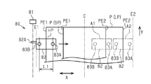
図17は、2つのセンサーにより媒体の側端を検出する方法を説明する模式図であり、媒体の裏面側から見た図となっている。図17に示すように、第1センサー83Aと第2センサー83Bは、キャリッジ82の上部に幅方向Xに中心間距離L1を離した状態で装着されている。キャリッジ82がホーム位置HPに位置するとき(図17の実線位置)、幅寸法の小さい小サイズの媒体SPの場合、両センサー83A,83Bが共に媒体SPの幅方向外側に位置して媒体SPを検知していない。一方、幅寸法の大きい大サイズの媒体LPの場合、キャリッジ82がホーム位置HPに位置するとき、ホーム位置HP側の一方のセンサー(図17の例では第2センサー83B)は媒体LPの幅方向X外側に位置して媒体LPを検知していない。これに対して、反ホーム位置AP側の他方のセンサー(図17の例では第1センサー83A)は、媒体LPと対向する位置にあって媒体LPを検知している。 FIG. 17 is a schematic diagram illustrating a method of detecting the side edge of the medium with two sensors, and is a diagram viewed from the back surface side of the medium. As shown in FIG. 17, the first sensor 83A and the second sensor 83B are mounted on the upper portion of the carriage 82 with a center-to-center distance L1 in the width direction X. When the carriage 82 is located at the home position HP (the solid line position in FIG. 17), in the case of a small size medium SP having a small width dimension, both the sensors 83A and 83B are located outside the medium SP in the width direction to move the medium SP. Not detected. On the other hand, in the case of a large size medium LP having a large width dimension, when the carriage 82 is located at the home position HP, one sensor on the home position HP side (the second sensor 83B in the example of FIG. 17) is in the width direction of the medium LP. It is located outside X and does not detect the medium LP. On the other hand, the other sensor (first sensor 83A in the example of FIG. 17) on the side of the anti-home position AP detects the medium LP at a position facing the medium LP.

本例では、最大幅の媒体Pが検出対象である場合、キャリッジ82が移動可能範囲における左側のエンド位置E1(例えばホーム位置HP)にあるとき、2つのセンサー83A,83Bのうち右側のセンサー83Aは最大幅の媒体Pを検知し、左側のセンサー83Bは最大幅の媒体Pを検知しない。一方、キャリッジ82が移動可能範囲における右側のエンド位置E2にあるとき、2つのセンサー83A,83Bのうち左側のセンサー83Bは最大幅の媒体Pを検知し、右側のセンサー83Aは最大幅の媒体Pを検知しない。このようにキャリッジ82の移動可能範囲が最大幅の媒体Pの幅の割に相対的に狭くなっている。このため、媒体検出装置80の幅方向Xのサイズ寸法が、最大幅の媒体Pの幅の割に相対的に短く抑えられており、媒体検出装置80をその長手方向が幅方向Xに一致する向きで装置本体20に設けても、印刷装置11の幅方向Xのサイズ寸法が相対的に短く抑えられている。 In this example, when the medium P having the maximum width is the detection target, when the carriage 82 is at the left end position E1 (for example, the home position HP) in the movable range, the right sensor 83A of the two sensors 83A and 83B. Detects the medium P having the maximum width, and the sensor 83B on the left side does not detect the medium P having the maximum width. On the other hand, when the carriage 82 is at the right end position E2 in the movable range, the left sensor 83B of the two sensors 83A and 83B detects the medium P having the maximum width, and the right sensor 83A detects the medium P having the maximum width. Is not detected. In this way, the movable range of the carriage 82 is relatively narrow relative to the width of the medium P having the maximum width. For this reason, the size dimension of the medium detection device 80 in the width direction X is kept relatively short relative to the width of the medium P having the maximum width, and the longitudinal direction of the medium detection device 80 coincides with the width direction X. Even if the printing apparatus 11 is provided in the orientation, the size of the printing apparatus 11 in the width direction X is relatively short.

図16に示す制御部120は、2つのセンサー83A,83Bのうち、媒体Pの両側の側端位置PE1,PE2を検出する側端検出処理で使用するセンサーの数を、媒体Pのサイズ(幅寸法)に応じて切り替える。つまり、制御部120は、幅情報に基づく媒体幅が設定幅以下である小サイズの媒体SPのときは、一方のセンサー(例えば第1センサー83A)のみを用いて、媒体SPの側端位置PE1,PE2を検出する。また、制御部120は、媒体幅が設定幅を超える大サイズの媒体LPのときは、第1及び第2センサー83A,83Bの両方を用いて、媒体LPの側端位置PE1,PE2を検出する。ここで、設定幅は、図17に示すように、キャリッジ82が実線で示すホーム位置HPにある状態において、2つのセンサー83A,83Bが共に媒体P(例えば媒体SP)を検知できない媒体幅のうち最大の媒体幅以上、かつ第1センサー83Aが媒体P(例えば媒体LP)を検知できる媒体幅のうち最小の媒体幅未満の値に設定されている。なお、図17においてキャリッジ82が移動可能な幅方向Xを左右方向とした場合、第1センサー83Aが右側のセンサーの一例に相当し、第2センサー83Bが左側のセンサーの一例に相当する。また、媒体Pの第1側端PE1が左側端の一例に相当し、第2側端PE2が右側端の一例に相当する。 The control unit 120 illustrated in FIG. 16 determines the number of sensors used in the side edge detection process for detecting the side edge positions PE1 and PE2 on both sides of the medium P, out of the two sensors 83A and 83B, as the size (width) of the medium P. Switch according to the dimensions. In other words, the control unit 120 uses only one sensor (for example, the first sensor 83A) when the medium width of the medium SP based on the width information is smaller than or equal to the set width, and uses only one sensor (the first sensor 83A). , PE2 is detected. In addition, when the medium width is a large size LP that exceeds the set width, the control unit 120 detects the side edge positions PE1 and PE2 of the medium LP using both the first and second sensors 83A and 83B. .. Here, as shown in FIG. 17, the set width is the medium width in which the two sensors 83A and 83B cannot detect the medium P (for example, the medium SP) when the carriage 82 is at the home position HP shown by the solid line. It is set to a value equal to or larger than the maximum medium width and less than the minimum medium width of the medium widths in which the first sensor 83A can detect the medium P (for example, the medium LP). When the width direction X in which the carriage 82 can move in FIG. 17 is the left-right direction, the first sensor 83A corresponds to an example of the right sensor, and the second sensor 83B corresponds to an example of the left sensor. The first side edge PE1 of the medium P corresponds to an example of the left side edge, and the second side edge PE2 corresponds to an example of the right side edge.

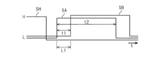
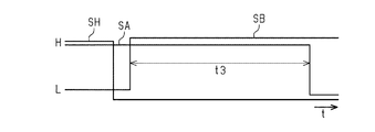
図18及び図19は、媒体Pの幅方向Xの両側の側端を検出するときに各センサー83A,83B,90から出力される検出信号を示す。図18は媒体幅が設定幅以下である小サイズの媒体SPの側端を検出するときの各検出信号の信号波形であり、図19は媒体幅が設定幅を超える大サイズの媒体LPの側端を検出するときの各検出信号の信号波形である。両図において横方向が時間t、縦方向が各検出信号SA,SB,SHの電圧レベルを示す。なお、キャリッジ82は一定速度V1で移動するため、両図における横方向の時間tは、電動モーター103のステップ数、すなわちキャリッジ82の移動距離に対応している。 18 and 19 show detection signals output from the respective sensors 83A, 83B, 90 when detecting side edges on both sides of the medium P in the width direction X. FIG. 18 is a signal waveform of each detection signal when detecting the side edge of a small-sized medium SP whose medium width is equal to or less than the set width, and FIG. 19 is a large-sized medium LP side where the medium width exceeds the set width. It is a signal waveform of each detection signal when detecting an edge. In both figures, the horizontal direction shows the time t, and the vertical direction shows the voltage levels of the detection signals SA, SB, SH. Since the carriage 82 moves at a constant speed V1, the horizontal time t in both figures corresponds to the number of steps of the electric motor 103, that is, the moving distance of the carriage 82.

図18に示すように、キャリッジ82がホーム位置HPに位置して(図17の実線位置)検出信号SHがHレベルにあるとき、検出対象が小サイズの媒体SPである場合、両センサー83A,83Bが共に媒体SPを検知しておらず、検出信号SA,SBは共にLレベルにある。キャリッジ82がホーム位置HPから移動を開始すると、まず右側の第1センサー83Aが左側の第1側端PE1を検知し、検出信号SAがLレベルからHレベルに立ち上がる。さらにキャリッジ82が2つのセンサー83A,83Bの中心間距離L1に相当する時間t1(=L1/V1)だけ移動すると、左側の第2センサー83Bが右側の第2側端PE2を検知し、検出信号SBがLレベルからHレベルに立ち上がる。次に第1センサー83Aが第1側端PE1の検出時点から媒体幅に相当する時間t2だけ移動すると、第1センサー83Aが第2側端PE2を検知し、検出信号SAがHレベルからLレベルに立ち下がる。なお、時間t2の期間に出力された電動モーター103のステップ数は、その期間におけるキャリッジ82の移動距離に相当し、これは媒体SPの幅に相当する。 As shown in FIG. 18, when the carriage 82 is located at the home position HP (the position shown by the solid line in FIG. 17) and the detection signal SH is at the H level, when the detection target is the medium SP of small size, both sensors 83A, Neither 83B detects the medium SP, and the detection signals SA and SB are both at the L level. When the carriage 82 starts moving from the home position HP, the first sensor 83A on the right side first detects the first side end PE1 on the left side, and the detection signal SA rises from the L level to the H level. Further, when the carriage 82 moves for a time t1 (=L1/V1) corresponding to the center-to-center distance L1 of the two sensors 83A and 83B, the left second sensor 83B detects the right second side end PE2, and the detection signal SB rises from L level to H level. Next, when the first sensor 83A moves from the time when the first side end PE1 is detected for a time t2 corresponding to the medium width, the first sensor 83A detects the second side end PE2 and the detection signal SA changes from H level to L level. Fall to. The number of steps of the electric motor 103 output during the period of time t2 corresponds to the moving distance of the carriage 82 during that period, which corresponds to the width of the medium SP.

また、図19に示すように、キャリッジ82がホーム位置HPに位置して(図17の実線位置)検出信号SHがHレベルにあるとき、検出対象が大サイズの媒体LPである場合、右側の第1センサー83Aは媒体LPを検知してHレベルにあり、左側の第2センサー83Bは媒体LPを検知しておらずLレベルにある。キャリッジ82がホーム位置から移動を開始すると、まず左側の第2センサー83Bが左側の第1側端PE1を検知し、検出信号SBがLレベルからHレベルに立ち上がる。さらにキャリッジ82が媒体幅に相当する時間t3だけ移動すると、右側の第1センサー83Aが右側の第2側端PE2を検知し、検出信号SAがHレベルからLレベルに立ち下がる。なお、時間t3の期間に出力された電動モーター103のステップ数は、その期間におけるキャリッジ82の移動距離に相当し、これは媒体LPの幅に相当する。 Further, as shown in FIG. 19, when the carriage 82 is located at the home position HP (the solid line position in FIG. 17) and the detection signal SH is at the H level, when the detection target is the medium LP of large size, The first sensor 83A detects the medium LP and is at the H level, and the second sensor 83B on the left side is not detecting the medium LP and is at the L level. When the carriage 82 starts moving from the home position, the left second sensor 83B first detects the left first side end PE1, and the detection signal SB rises from the L level to the H level. When the carriage 82 further moves for a time t3 corresponding to the medium width, the first sensor 83A on the right side detects the second side end PE2 on the right side, and the detection signal SA falls from the H level to the L level. The number of steps of the electric motor 103 output during the period of time t3 corresponds to the moving distance of the carriage 82 during that period, which corresponds to the width of the medium LP.

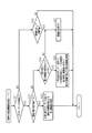
次に、図18〜図21を参照して、印刷装置11の作用について説明する。制御部120は、印刷装置11の電源が投入されると、制御部120は、図20に示される媒体側端検出処理を実行する。また、制御部120は、図20に示す媒体側端検出処理において、センサー83A,83Bのうち一方の故障を検出した場合は、図21に示される故障時の媒体側端検出処理を実行する。 Next, the operation of the printing device 11 will be described with reference to FIGS. When the printing apparatus 11 is powered on, the control unit 120 executes the medium side edge detection process shown in FIG. Further, when the controller 120 detects a failure of one of the sensors 83A and 83B in the medium side edge detection processing shown in FIG. 20, it executes the medium side edge detection processing at the time of failure shown in FIG.

まずステップS11では、センサー故障検出処理を行う。このセンサー故障検出処理は、搬送ユニット32が媒体Pを搬送していないときに行う。ここで、媒体Pを搬送していないときとは、印刷装置11の電源オン時、印刷ジョブの受信を待っている印刷待機状態にあるとき、休止モード(スリープモード)からの復帰時等が挙げられる。本例では、光反射面71Cは、センサー83A,83Bの移動経路と対向する領域に設けられているので、センサー83A,83Bは、移動経路上のどの位置にあっても、光反射面71Cと対向する。例えばキャリッジ82がホーム位置HPにある状態で、センサー83A,83Bは光を出射し、その出射した光が光反射面71Cで反射した反射光を受光する。制御部120は、センサー83A,83Bからの光が光反射面71Cで反射した反射光を受光した受光量が閾値を超えず、その検出信号が媒体ありのときのHレベルである場合は、故障と判定する。この故障検出処理を2つのセンサー83A,83Bのそれぞれについて行う。なお、センサー83A,83Bの移動経路のうち一部と対向する領域にしか光反射面71Cが存在せず、2つのセンサー83A,83Bが光反射面71Cと対向する位置にない場合、制御部120は、電動モーター103を駆動制御し、2つのセンサー83A,83が光反射面71Cと対向する位置に配置する。そして、制御部120は、2つのセンサー83A,83Bを光反射面71Cと対向する位置に配置した状態で発光させることにより、各検出信号に基づいて故障検出処理を行う。 First, in step S11, a sensor failure detection process is performed. This sensor failure detection process is performed when the transport unit 32 is not transporting the medium P. Here, when the medium P is not being conveyed, the printing apparatus 11 is powered on, is in a print standby state waiting for the reception of a print job, and is returning from a sleep mode (sleep mode). Be done. In this example, since the light reflecting surface 71C is provided in a region facing the movement paths of the sensors 83A and 83B, the sensors 83A and 83B are not affected by the light reflecting surface 71C at any position on the movement path. opposite. For example, when the carriage 82 is at the home position HP, the sensors 83A and 83B emit light and the emitted light is reflected by the light reflecting surface 71C. If the amount of light received from the light reflected from the light reflecting surface 71C by the light from the sensors 83A and 83B does not exceed the threshold and the detection signal is at the H level when the medium is present, the control unit 120 fails. To determine. This failure detection process is performed for each of the two sensors 83A and 83B. In addition, when the light reflecting surface 71C is present only in a region facing a part of the movement paths of the sensors 83A and 83B and the two sensors 83A and 83B are not in positions facing the light reflecting surface 71C, the control unit 120. Controls the electric motor 103 and arranges the two sensors 83A and 83 at positions facing the light reflecting surface 71C. Then, the control unit 120 causes the two sensors 83A and 83B to emit light in a state of being arranged at a position facing the light reflection surface 71C, thereby performing the failure detection process based on each detection signal.

ステップS12では、センサーが故障であるか否かを判定する。この故障判定では、2つのセンサー83A,83Bのうち1つでも故障であれば故障と判定する。1つでも故障であればステップS13に進み、故障でなければステップS14に進む。 In step S12, it is determined whether the sensor is out of order. In this failure determination, if even one of the two sensors 83A and 83B has a failure, it is determined to be a failure. If even one is in failure, the process proceeds to step S13, and if not, the process proceeds to step S14.

ステップS13では、故障報知を行う。すなわち、制御部120は、例えば表示部15に故障の旨のメッセージを表示することで、ユーザーに故障の旨を報知する。なお、故障報知は発光ダイオード等の発光部の発光又は点滅等による報知、ブザー又は音声による報知、これら複数種の報知方法を組み合わせて報知するものでもよい。 In step S13, failure notification is performed. That is, the control unit 120 notifies the user of the failure, for example, by displaying a message indicating the failure on the display unit 15. Note that the failure notification may be a notification by light emission or blinking of a light emitting portion such as a light emitting diode, a buzzer or a sound, or a combination of a plurality of these notification methods.

ステップS14では、幅情報を含む印刷ジョブを受け付けたか否かを判断する。本例の印刷装置11では、印刷ジョブには印刷設定情報が含まれ、その印刷設定情報の中の1つに媒体の幅情報(例えば用紙サイズ)が含まれている。つまり、このステップS14の処理は印刷ジョブを受け付けたか否かを判断するに同義である。なお、印刷ジョブ以外の方法で印刷の指示を受け付ける場合、例えば印刷装置11に不図示のメモリーカードを接続して操作部16を操作してメモリーカードから選択した画像を印刷する場合、制御部120は操作部16で選択された媒体Pの幅情報(例えば用紙サイズ)を取得する。 In step S14, it is determined whether a print job including width information has been received. In the printing apparatus 11 of this example, the print job includes print setting information, and one of the print setting information includes medium width information (for example, paper size). That is, the process of step S14 is synonymous with determining whether a print job is accepted. When a print instruction is received by a method other than a print job, for example, when a memory card (not shown) is connected to the printing apparatus 11 and the operation unit 16 is operated to print an image selected from the memory card, the control unit 120 Acquires width information (for example, paper size) of the medium P selected by the operation unit 16.

ステップS15では、センサーが全て正常であるか否かを判定する。詳しくは、制御部120の故障検出部143が、第1及び第2センサー83A,83Bの故障を検出する故障検出処理を行い、その故障検出処理結果に基づきセンサー83A,83Bが全て正常であるか否かを判定する。故障検出処理としては、媒体Pが給送される前の媒体の無い状態の下で、光反射面71Cで反射した反射光を受光しているはずのセンサー83A,83Bからの検出信号SA,SBの値が、媒体が無いときの値(例えばLレベル)でなく、媒体を検知しているときの値(例えばHレベル)であれば、そのセンサーを故障と判定する。全てのセンサー83A,83Bが正常であれば、ステップS16に進み、センサー83A,83Bのうち1つでも故障がある場合はステップS19に進む。 In step S15, it is determined whether all the sensors are normal. Specifically, the failure detection unit 143 of the control unit 120 performs a failure detection process for detecting a failure of the first and second sensors 83A, 83B, and whether all the sensors 83A, 83B are normal based on the result of the failure detection process. Determine whether or not. As the failure detection processing, the detection signals SA and SB from the sensors 83A and 83B, which should receive the reflected light reflected by the light reflection surface 71C, in the absence of the medium before the medium P is fed. If the value of is not the value when there is no medium (for example, L level) but the value when the medium is being detected (for example, H level), the sensor is determined to be defective. If all the sensors 83A and 83B are normal, the process proceeds to step S16, and if any one of the sensors 83A and 83B has a failure, the process proceeds to step S19.

ステップS16では、媒体の幅は設定幅以下であるか否かを判定する。そして、制御部120は、幅情報から取得した媒体Pの幅が設定幅以下であれば、つまり媒体Pが小サイズの媒体SPであれば、ステップS17に進む。一方、幅情報から取得した媒体Pの幅が設定幅を超えれば、つまり媒体Pが大サイズの媒体LPであれば、ステップS18に進む。 In step S16, it is determined whether the width of the medium is less than or equal to the set width. Then, the control unit 120 proceeds to step S17 if the width of the medium P acquired from the width information is equal to or smaller than the set width, that is, if the medium P is the small-sized medium SP. On the other hand, if the width of the medium P acquired from the width information exceeds the set width, that is, if the medium P is a large-sized medium LP, the process proceeds to step S18.

ステップS17では、1つのセンサーを用いて媒体の両側端を検出する第1側端検出処理を行う。制御部120のキャリッジ制御部142は、モーター駆動回路131を介して電動モーター103を駆動制御し、キャリッジ82を幅方向Xに移動させる。電動モーター103がステッピングモーターである本例では、キャリッジ制御部142は、ステップ数を指示することで電動モーター103を制御する。カウンター145は、キャリッジ82がホーム位置HPにあって位置センサー90が被検出部82Aを検知したときにリセットされ、制御に使用するステップ数をキャリッジ82の進行方向に応じて加算又は減算する計数処理を行う。これによりカウンター145には、キャリッジ82の幅方向Xにおける位置に応じた計数値が格納される。キャリッジ制御部142は、幅情報に基づき媒体Pの幅が設定幅以下の例えばA4判などの小サイズの媒体SPである場合、キャリッジ82をホーム位置HPから図17に2点鎖線で示す位置A1まで移動させる。このキャリッジ82の移動過程で、検出処理部144は、一方の第1センサー83Aのみを用いて小サイズの媒体SPの両側の側端位置PE1,PE2を検出する。 In step S17, a first side edge detection process of detecting both side edges of the medium using one sensor is performed. The carriage control unit 142 of the control unit 120 drives and controls the electric motor 103 via the motor drive circuit 131 to move the carriage 82 in the width direction X. In this example in which the electric motor 103 is a stepping motor, the carriage control unit 142 controls the electric motor 103 by instructing the number of steps. The counter 145 is reset when the carriage 82 is at the home position HP and the position sensor 90 detects the detected portion 82A, and count processing for adding or subtracting the number of steps used for control according to the traveling direction of the carriage 82. I do. As a result, the counter 145 stores the count value according to the position of the carriage 82 in the width direction X. When the width of the medium P is a small size medium SP such as A4 size which is equal to or smaller than the set width based on the width information, the carriage control unit 142 moves the carriage 82 from the home position HP to a position A1 shown by a two-dot chain line in FIG. Move to. In the process of moving the carriage 82, the detection processing unit 144 detects the side edge positions PE1 and PE2 on both sides of the small-sized medium SP using only one of the first sensors 83A.

このとき、図18に示すように、制御部120は、位置センサー90の検出信号SHと、第1センサー83Aの検出信号SAと、第2センサー83Bの検出信号SBとを入力する。制御部120の検出処理部144は、第1センサー83Aの検出信号SAを監視し、検出信号SAがLレベルからHレベルに立ち上がると、そのときのカウンター145の計数値を取得し、その計数値とキャリッジ幅中心位置から第1センサー83Aまでの幅方向Xの既知の第1距離(例えばL1/2)とを用いて第1側端位置PE1を算出する。その算出した第1側端位置PE1はメモリーに記憶される。そして、そのキャリッジ82の移動中に第1センサー83Aの検出信号SAがHレベルからLレベルに立ち下がると、そのときのカウンター145の計数値を取得し、その計数値と前述の既知の第1距離とを用いて第2側端位置PE2を算出し、その算出した第2側端位置PE2をメモリーに記憶する。こうしてキャリッジ82がホーム位置HPにあるときに2つのセンサー83A,83Bが共に媒体SPを検知していなければ、キャリッジ82の媒体検出時の移動過程の進行方向前側に位置する第1センサー83Aのみを用いることで、相対的にキャリッジ82の短い移動距離で、媒体Pの両側の側端位置PE1,PE2を検出できる。 At this time, as shown in FIG. 18, the control unit 120 inputs the detection signal SH of the position sensor 90, the detection signal SA of the first sensor 83A, and the detection signal SB of the second sensor 83B. The detection processing unit 144 of the control unit 120 monitors the detection signal SA of the first sensor 83A, and when the detection signal SA rises from the L level to the H level, acquires the count value of the counter 145 at that time, and the count value thereof. The first side end position PE1 is calculated by using a known first distance (for example, L1/2) in the width direction X from the carriage width center position to the first sensor 83A. The calculated first side end position PE1 is stored in the memory. Then, when the detection signal SA of the first sensor 83A falls from the H level to the L level during the movement of the carriage 82, the count value of the counter 145 at that time is acquired, and the count value and the above-mentioned known first value. The second side end position PE2 is calculated using the distance and the calculated second side end position PE2 is stored in the memory. In this way, if the two sensors 83A and 83B do not detect the medium SP when the carriage 82 is at the home position HP, only the first sensor 83A located on the front side in the traveling direction of the movement process of the carriage 82 when detecting the medium is detected. By using it, the side edge positions PE1 and PE2 on both sides of the medium P can be detected with a relatively short moving distance of the carriage 82.

図20におけるステップS18では、2つのセンサーを用いて媒体の両側端を検出する第2側端検出処理を行う。制御部120のキャリッジ制御部142は、ステップ数を指示してモーター駆動回路131を介して電動モーター103を駆動制御し、キャリッジ82を幅方向Xに移動させる。このとき、カウンター145には、キャリッジ82がホーム位置HPにあるときを原点とするキャリッジ82の幅方向Xにおける位置が計数される。キャリッジ制御部142は、幅情報に基づき媒体Pの幅が設定幅を超える例えばA3判などの大サイズの媒体SPである場合、キャリッジ82をホーム位置HPから幅方向Xに例えば図17に2点鎖線で示す位置A2まで移動させる。このキャリッジ82の移動過程で、検出処理部144は、第1及び第2センサー83A,83Bの両方を用いて、大サイズの媒体LPの幅方向Xの両側の側端位置PE1,PE2を検出する。 In step S18 in FIG. 20, a second side edge detection process of detecting both side edges of the medium using two sensors is performed. The carriage control unit 142 of the control unit 120 instructs the number of steps to drive and control the electric motor 103 via the motor drive circuit 131, and moves the carriage 82 in the width direction X. At this time, the counter 145 counts the position in the width direction X of the carriage 82 with the origin when the carriage 82 is at the home position HP. When the width of the medium P is larger than the set width based on the width information, for example, a large size medium SP such as A3 size, the carriage control unit 142 moves the carriage 82 from the home position HP in the width direction X to two points in FIG. 17, for example. It is moved to the position A2 shown by the chain line. In the process of moving the carriage 82, the detection processing unit 144 uses both the first and second sensors 83A and 83B to detect the side edge positions PE1 and PE2 on both sides of the large size medium LP in the width direction X. ..

詳しくは、図19に示すように、キャリッジ82がホーム位置HPにあって検出信号SHがHレベルにあるとき、第1センサー83Aは媒体LPを検知した状態にあってその検出信号SAはHレベルにある。一方、媒体LPを検知していない第2センサー83Bの検出信号SBはLレベルにある。キャリッジ82がホーム位置HPから移動を開始すると、検出処理部144は、まず第2センサー83Bの検出信号SBを監視する。検出処理部144は、第2センサー83Bの検出信号SBがLレベルからHレベルに立ち上がると、そのときのカウンター145の計数値を取得し、その計数値とキャリッジ幅中心位置から第2センサー83Bまでの幅方向Xの既知の第2距離(例えばL1/2)とを用いて第1側端位置PE1を算出する。その算出した第1側端位置PE1はメモリーに記憶される。そして、その後のキャリッジ82の移動中に第1センサー83Aの検出信号SAがHレベルからLレベルに立ち下がると、そのときのカウンター145の計数値を取得し、その計数値と前述の既知の第1距離とを用いて第2側端位置PE2を算出し、その算出した第2側端位置PE2をメモリーに記憶する。こうしてキャリッジ82がホーム位置HPにあるときに2つのセンサー83A,83Bのうち一方が媒体LPを検知していなければ、キャリッジ82の媒体検出時の移動過程の進行方向後側に位置する第2センサー83Bで第1側端位置PE1を検出し、進行方向前側に位置する第1センサー83Aで第2側端位置PE2を検出する。このため、相対的にキャリッジ82の短い移動距離で、媒体Pの両側の側端位置PE1,PE2を検出できる。 Specifically, as shown in FIG. 19, when the carriage 82 is at the home position HP and the detection signal SH is at the H level, the first sensor 83A is in the state of detecting the medium LP and the detection signal SA is at the H level. It is in. On the other hand, the detection signal SB of the second sensor 83B that does not detect the medium LP is at the L level. When the carriage 82 starts moving from the home position HP, the detection processing unit 144 first monitors the detection signal SB of the second sensor 83B. When the detection signal SB of the second sensor 83B rises from the L level to the H level, the detection processing unit 144 acquires the count value of the counter 145 at that time and the count value and the carriage width center position to the second sensor 83B. The first side end position PE1 is calculated using the known second distance (for example, L1/2) in the width direction X of. The calculated first side end position PE1 is stored in the memory. Then, when the detection signal SA of the first sensor 83A falls from the H level to the L level during the subsequent movement of the carriage 82, the count value of the counter 145 at that time is acquired, and the count value and the above-mentioned known first value are acquired. The second side end position PE2 is calculated using 1 distance, and the calculated second side end position PE2 is stored in the memory. Thus, if one of the two sensors 83A and 83B does not detect the medium LP when the carriage 82 is at the home position HP, the second sensor located on the rear side in the traveling direction of the moving process of the carriage 82 when detecting the medium. 83B detects the first side end position PE1, and the first sensor 83A located on the front side in the traveling direction detects the second side end position PE2. Therefore, the side end positions PE1 and PE2 on both sides of the medium P can be detected with a relatively short movement distance of the carriage 82.

図20におけるステップS19では、故障時の媒体側端検出処理を行う。この故障時の媒体側端検出処理は、制御部120のコンピューターが、図21に示す故障時の媒体側端検出処理ルーチンを実行することにより行われる。 In step S19 in FIG. 20, a medium side edge detection process at the time of failure is performed. The computer of the control unit 120 executes the medium side edge detection processing at the time of failure by executing the medium side edge detection processing routine at the time of failure shown in FIG.

以下、図21を参照して、制御部120が行う故障時の媒体側端検出処理について説明する。
まずステップS21では、一方のセンサーのみの故障であるか否かを判定する。すなわち、制御部120は、図20のステップS11におけるセンサー故障検出処理の検出結果を用いて、一方のセンサーのみの故障であるか否かを判定する。一方のセンサーのみの故障であればステップS22に進む。また、一方のセンサーのみの故障でなければ、つまり2つのセンサーが共に故障であれば、ステップS26に進む。
Hereinafter, with reference to FIG. 21, the medium side edge detection process performed by the control unit 120 when a failure occurs will be described.
First, in step S21, it is determined whether or not only one sensor is in failure. That is, the control unit 120 uses the detection result of the sensor failure detection process in step S11 of FIG. 20 to determine whether or not only one sensor is in failure. If only one of the sensors is out of order, the process proceeds to step S22. If only one of the sensors is out of order, that is, if both sensors are out of order, the process proceeds to step S26.

ステップS22では、媒体の幅は設定幅以下であるか否かを判断する。この判断処理は、図20におけるステップS16の判断処理と同じであり、幅情報に基づいて行う。媒体Pの幅が設定幅以下であればステップS23に進む。一方、媒体Pの幅が設定幅以下でなければ、つまり媒体Pの幅が設定幅を超えていれば、ステップS24に進む。 In step S22, it is determined whether the width of the medium is less than or equal to the set width. This determination process is the same as the determination process of step S16 in FIG. 20, and is performed based on the width information. If the width of the medium P is less than or equal to the set width, the process proceeds to step S23. On the other hand, if the width of the medium P is not less than the set width, that is, if the width of the medium P exceeds the set width, the process proceeds to step S24.

ステップS23では、正常な他方のセンサーを用いて媒体の両側端を検出する第3側端検出処理を行う。例えば第1センサー83Aが正常で第2センサー83Bが故障である場合、正常な第1センサー83Aを用いて媒体Pの両側端位置PE1,PE2を検出する、図19におけるステップS17と同様の第1側端検出処理を、第3側端検出処理として行う。一方、第1センサー83Aが故障で第2センサー83Bが正常である場合、正常な第2センサー83Bを用いて媒体Pの両側端位置PE1,PE2を検出する第3側端検出処理を行う。後者の場合、第2センサー83Bからの検出信号SBのLレベルからHレベルへの立ち上がり時のカウンター145の計数値を取得し、その計数値と前述の既知の第2距離とを用いて第1側端位置PE1を算出し、その算出した第1側端位置PE1をメモリーに記憶する。また、検出信号SBのHレベルからLレベルへの立ち下がり時のカウンター145の計数値を取得し、その計数値と前述の既知の第2距離とを用いて第2側端位置PE2を算出し、その算出した第2側端位置PE2をメモリーに記憶する。 In step S23, a third side edge detection process for detecting both side edges of the medium using the other normal sensor is performed. For example, when the first sensor 83A is normal and the second sensor 83B is defective, the normal first sensor 83A is used to detect the side end positions PE1 and PE2 of the medium P, and the first similar to step S17 in FIG. The side edge detection process is performed as the third side edge detection process. On the other hand, when the first sensor 83A is out of order and the second sensor 83B is normal, the third side edge detection process of detecting the side edge positions PE1 and PE2 of the medium P is performed using the normal second sensor 83B. In the latter case, the count value of the counter 145 when the detection signal SB from the second sensor 83B rises from the L level to the H level is acquired, and the count value and the above-described known second distance are used to make the first value. The side end position PE1 is calculated, and the calculated first side end position PE1 is stored in the memory. Further, the count value of the counter 145 when the detection signal SB falls from the H level to the L level is acquired, and the second side end position PE2 is calculated using the count value and the above-mentioned known second distance. , And stores the calculated second side end position PE2 in the memory.

ステップS24では、推定を伴う第4側端検出処理を行ってよいか否かを判断する。本例では、制御部120は、推定を伴う第4側端検出処理を行ってよいか否かの問合せメッセージを表示部15に表示し、その問合せの応答としてユーザーが操作部16を操作した操作信号に基づいて第4側端検出処理の実行の可否を判断する。あるいは、ユーザーが印刷装置11の操作部16を操作して予め登録しておいた登録情報をメモリーから読み出し、その登録情報に基づいて第4側端検出処理の実行の可否を判断する。制御部120は、第4側端検出処理の実行が許可されればステップS25に進み、第4側端検出処理の実行が許可されなければステップS27に進む。 In step S24, it is determined whether or not the fourth side edge detection process involving estimation may be performed. In this example, the control unit 120 displays on the display unit 15 an inquiry message as to whether or not the fourth side edge detection process with estimation may be performed, and the user operates the operation unit 16 as a response to the inquiry. Whether to execute the fourth side edge detection process is determined based on the signal. Alternatively, the user operates the operation unit 16 of the printing apparatus 11 to read the registration information registered in advance from the memory, and determines whether to execute the fourth side edge detection process based on the registration information. The control unit 120 proceeds to step S25 if execution of the fourth side edge detection process is permitted, and proceeds to step S27 if execution of the fourth side edge detection process is not permitted.

ステップS25では、正常な他方のセンサーを用いて一方の側端を検出し、一方の側端の検出結果と幅情報とを用いて他方の側端を推定する第4側端検出処理を行う。図17に示すように、本例の印刷装置11では、キャリッジ82をホーム位置HP側のエンド位置E1から反ホーム位置AP側のエンド位置E2まで移動できる移動可能範囲が相対的に短くなっている。このため、媒体検出装置80の幅方向Xのサイズ寸法、ひいては印刷装置11の幅方向Xのサイズ寸法を短くし、印刷装置11のコンパクト化に寄与する。しかし、キャリッジ82の移動可能範囲が相対的に短いことから、大サイズの媒体LPが検出対象である場合、正常な他方のセンサーだけでは、媒体LPの両側の側端を検出できない。このため、正常なセンサーで一方の側端位置を検出し、他方のセンサーの故障により検出できない他方の側端位置は、正常なセンサーで検出した側端位置と幅情報とを用いた演算で推定する。詳しくは、制御部120は、第1及び第2センサー83A,83Bのうち故障でない他方のセンサーにより一方の側端を検出する。例えば第1センサー83Aが正常で第2センサー83Bが故障の場合、第1センサー83Aにより一方の側端位置PE2を検出する。また、第1センサー83Aが故障で第2センサー83Bが正常の場合、第2センサー83Bにより一方の側端位置PE1を検出する。検出処理部144の演算部146は、この検出した一方の側端位置と媒体Pの幅情報とを用いて他方の側端位置を算出する。他方のセンサーで検出した一方の側端位置をx1、媒体幅をW1とすると、媒体Pの他方の側端位置x2は、第1センサー83Aが正常である場合にx2=x1−W1、第2センサー83Bが正常である場合にx1+W1により算出される。こうして第4側端検出処理によって、媒体Pの両側の側端位置PE1,PE2が取得される。 In step S25, a fourth side edge detection process of detecting one side edge using the other normal sensor and estimating the other side edge using the detection result of the one side edge and the width information is performed. As shown in FIG. 17, in the printing apparatus 11 of this example, the movable range in which the carriage 82 can be moved from the home position HP side end position E1 to the anti-home position AP side end position E2 is relatively short. . Therefore, the size dimension of the medium detection device 80 in the width direction X and the size dimension of the printing device 11 in the width direction X are shortened, which contributes to downsizing of the printing device 11. However, since the movable range of the carriage 82 is relatively short, when the medium LP having a large size is a detection target, the side edges on both sides of the medium LP cannot be detected only by the other normal sensor. Therefore, a normal sensor detects one side end position, and the other side end position that cannot be detected due to a failure of the other sensor is estimated by calculation using the side end position detected by the normal sensor and the width information. To do. Specifically, the control unit 120 detects one side end by the other sensor, which is not a failure, of the first and second sensors 83A and 83B. For example, when the first sensor 83A is normal and the second sensor 83B is out of order, the one side end position PE2 is detected by the first sensor 83A. When the first sensor 83A is out of order and the second sensor 83B is normal, the second sensor 83B detects one side end position PE1. The calculation unit 146 of the detection processing unit 144 calculates the other side end position using the detected one side end position and the width information of the medium P. Assuming that one side end position detected by the other sensor is x1 and the medium width is W1, the other side end position x2 of the medium P is x2=x1−W1, the second side position x2 when the first sensor 83A is normal. Calculated by x1+W1 when the sensor 83B is normal. Thus, the side edge positions PE1 and PE2 on both sides of the medium P are acquired by the fourth side edge detection processing.

制御部120は、媒体側端検出処理によって取得した媒体Pの両側の側端位置PE1,PE2に基づいて、印刷ヘッド34の幅方向Xにおける印刷範囲を制御する。この結果、媒体Pの幅方向Xにおいて適切な位置範囲に印刷が施される。なお、制御部120は、側端位置PE1,PE2から媒体Pの幅を取得し、その幅が幅情報から取得した媒体幅と許容範囲を超えて異なる場合は、媒体サイズのエラーの旨のメッセージを表示部15に表示させる。 The control unit 120 controls the printing range in the width direction X of the print head 34 based on the side edge positions PE1 and PE2 on both sides of the medium P acquired by the medium side edge detection process. As a result, printing is performed in an appropriate position range in the width direction X of the medium P. Note that the control unit 120 acquires the width of the medium P from the side end positions PE1 and PE2, and if the width is different from the medium width acquired from the width information beyond the allowable range, a message indicating a medium size error is displayed. Is displayed on the display unit 15.

ステップS26では、側端検出なしで印刷を実施してよいか否かを判断する。本例では、例えば制御部120は、問合せメッセージを表示部15に表示させ、ユーザーに媒体Pの側端の検出なしで印刷を実施してよいか否かを問い合わせる。制御部120は、操作部16からの操作信号に基づき、側端検出なしで印刷を実施する旨の応答を受け付けると(S26で肯定判定)、ステップS27に進み、一方、側端検出なしで印刷を実施しない旨の応答を受け付けると(S26で否定判定)、当該ルーチンを終了する。後者の場合、印刷自体が中止される。 In step S26, it is determined whether printing can be performed without detecting the side edge. In this example, for example, the control unit 120 causes the display unit 15 to display an inquiry message and inquires of the user whether or not printing may be performed without detecting the side edge of the medium P. When the control unit 120 receives a response indicating that the printing is performed without the side edge detection based on the operation signal from the operation unit 16 (Yes in S26), the process proceeds to step S27, and the printing is performed without the side edge detection. When a response not to execute is received (negative determination in S26), the routine ends. In the latter case, printing itself is stopped.

ステップS27では、側端検出処理を中止する。制御部120は、側端検出処理の実行の可否を管理するフラグを備え、フラグに中止の旨の値を書き込む。この場合、制御部120は、側端検出処理を行うことなく、印刷ジョブデータPDに基づく印刷を実施する。このとき、制御部120は、幅情報から取得した媒体幅に基づいて印刷ヘッド34の印刷範囲を制御する。 In step S27, the side edge detection process is stopped. The control unit 120 includes a flag that manages whether or not the side edge detection process can be executed, and writes a value indicating cancellation to the flag. In this case, the control unit 120 performs printing based on the print job data PD without performing side edge detection processing. At this time, the control unit 120 controls the print range of the print head 34 based on the medium width acquired from the width information.

なお、図20において、ステップS24及びステップS25の処理を廃止し、推定を伴う第4側端検出処理を行わない構成としてもよい。また、ステップS24で否定判定のときは、ステップS26の判断処理へ進んでもよい。さらに、ステップS26の処理を廃止し、全てのセンサー83A,83Bが故障である場合は、印刷を中止してもよい。 Note that, in FIG. 20, the processing of steps S24 and S25 may be omitted and the fourth side edge detection processing with estimation may not be performed. In addition, when the negative determination is made in step S24, the determination process of step S26 may be performed. Furthermore, the process of step S26 may be abolished, and if all the sensors 83A and 83B are defective, printing may be stopped.

以上詳述した第1実施形態によれば、以下に示す効果を得ることができる。
(1)印刷ヘッド34よりも媒体Pの搬送方向Yの上流側に、媒体Pの搬送方向Yと交差する幅方向Xの側端を検出する媒体検出装置80を配置した。媒体検出装置80は、印刷ヘッド34よりも搬送方向Yの上流側の位置で印刷ヘッド34と独立して幅方向Xに移動可能なキャリッジ82と、キャリッジ82における幅方向Xの異なる位置に設けられた2つのセンサー83A,83Bと、キャリッジ82を移動させる動力源の一例としての電動モーター103とを備える。制御部120は、電動モーター103を制御してキャリッジ82を移動させることでセンサー83A,83Bに媒体Pの幅方向Xの側端を検出させる。キャリッジ82には2つのセンサー83A,83Bが幅方向Xの異なる位置に配置されているので、2つのセンサー83A,83Bを使い分けることにより、媒体Pの幅方向Xの側端を検出する際のキャリッジ82の移動量を少なく済ませられる。よって、印刷ヘッド34が移動するか否かの印刷方式(例えばライン印刷方式やシリアル印刷方式)に依存することなく、媒体Pの幅方向Xの両側の側端を検出でき、しかも媒体検出装置80を設けた割に、印刷装置11の幅方向サイズ寸法を比較的短く抑えることができる。
According to the first embodiment described in detail above, the following effects can be obtained.
(1) A medium detection device 80 that detects a side edge in the width direction X that intersects the transport direction Y of the medium P is arranged upstream of the print head 34 in the transport direction Y of the medium P. The medium detection device 80 is provided at a position upstream of the print head 34 in the transport direction Y and movable in the width direction X independently of the print head 34, and at a different position in the width direction X of the carriage 82. Also, two sensors 83A and 83B and an electric motor 103 as an example of a power source for moving the carriage 82 are provided. The control unit 120 controls the electric motor 103 to move the carriage 82 so that the sensors 83A and 83B detect the side edge of the medium P in the width direction X. Since the two sensors 83A and 83B are arranged at different positions in the width direction X on the carriage 82, the carriage used when detecting the side edge of the medium P in the width direction X by properly using the two sensors 83A and 83B. The movement amount of 82 can be reduced. Therefore, both side edges of the medium P in the width direction X can be detected without depending on the printing method (for example, the line printing method or the serial printing method) whether the print head 34 moves or not, and the medium detecting device 80 However, the size of the printing device 11 in the width direction can be suppressed to be relatively short.

(2)キャリッジ82が、搬送ユニット32により搬送される媒体Pの搬送経路30に対して印刷ヘッド34側とは反対側の位置で幅方向Xに移動可能に設けられることで、光学式センサーからなる2つのセンサー83A,83Bは、搬送経路30を挟んで印刷ヘッド34側とは反対側の位置から媒体Pに向かって光を照射する。よって、2つのセンサー83A,83Bが、媒体Pに対して印刷ヘッド34と同じ側に配置される構成とした場合に比べ、印刷ヘッド34からのインクミストが付着しにくい。そのため、インク汚れに起因するセンサー83A,83Bの検出精度の低下を回避し易い。 (2) The carriage 82 is provided so as to be movable in the width direction X at a position opposite to the print head 34 side with respect to the transport path 30 of the medium P transported by the transport unit 32, so that the optical sensor can be operated. The two sensors 83</b>A and 83</b>B irradiate the medium P from the position opposite to the print head 34 side with the transport path 30 interposed therebetween. Therefore, as compared with the case where the two sensors 83A and 83B are arranged on the same side as the print head 34 with respect to the medium P, the ink mist from the print head 34 is less likely to adhere. Therefore, it is easy to avoid a decrease in detection accuracy of the sensors 83A and 83B due to ink stains.

(3)媒体検出装置80の筐体81は、搬送経路30を搬送される媒体Pを支持する媒体支持部81Bを有し、その媒体支持部81Bに2つのセンサー83A,83Bからの光を透過可能な窓部88を設けている。よって、センサー83A,83Bは窓部88によって保護されるので、媒体Pから出た紙粉等の塵埃や印刷ヘッド34からのインクミスト等により直接は汚れないので、センサー83A,83Bの検出精度を比較的高く維持できる。また、窓部88が媒体支持部81Bの一部を兼ね、窓部88の上面を摺動する媒体Pとセンサー83A,83Bとの距離を比較的短くでき、この点からもセンサー83A,83Bの検出精度を高く維持できる。 (3) The housing 81 of the medium detection device 80 has a medium support portion 81B that supports the medium P conveyed on the conveyance path 30, and the medium support portion 81B transmits the light from the two sensors 83A and 83B. A possible window portion 88 is provided. Therefore, since the sensors 83A and 83B are protected by the window 88, they are not directly contaminated by dust such as paper dust from the medium P or ink mist from the print head 34. Therefore, the detection accuracy of the sensors 83A and 83B is improved. Can be kept relatively high. Further, the window portion 88 also serves as a part of the medium support portion 81B, and the distance between the medium P sliding on the upper surface of the window portion 88 and the sensors 83A, 83B can be made relatively short. From this point as well, the sensors 83A, 83B High detection accuracy can be maintained.

(4)媒体支持部81Bには、2つの窓部88が幅方向Xに沿って配置されている。よって、センサー83A,83Bの移動エリアに亘る1つの長い窓部を設けた構成に比べ、媒体支持部81Bの強度を比較的高く確保できるうえ、窓部88の部品コストを相対的に安価に抑えることができる。 (4) Two windows 88 are arranged along the width direction X in the medium supporting portion 81B. Therefore, the strength of the medium support portion 81B can be kept relatively high and the cost of parts of the window portion 88 can be kept relatively low as compared with the configuration in which one long window portion is provided over the moving areas of the sensors 83A and 83B. be able to.

(5)複数の窓部88は、2つのセンサー83A,83Bによって最小幅から最大幅までの媒体Pの幅方向Xの両側の側端をそれぞれ異なる窓部88を通して検出できる位置に配置されている。例えば最小幅から最大幅までの媒体Pの両側の側端を連続的に検出できる。例えば定形の媒体P以外の不定形の媒体Pが搬送されても、その不定形の媒体Pの側端を検出できる。 (5) The plurality of window portions 88 are arranged at positions where the two sensors 83A and 83B can detect the side edges on both sides of the medium P in the width direction X from the minimum width to the maximum width through the different window portions 88, respectively. .. For example, the side edges on both sides of the medium P from the minimum width to the maximum width can be continuously detected. For example, even if an irregular medium P other than the regular medium P is conveyed, the side edge of the irregular medium P can be detected.

(6)媒体検出装置80の動力源の一例である電動モーター103をステッピングモーターとしたので、直流モーター(DCモーター)を使用した場合に必要になる、キャリッジ82の位置を取得するためのエンコーダー等が不要になる。よって、直流モーターを使用した場合に比べ、媒体検出装置80の部品点数を少なく抑えることができる。例えば媒体検出装置80の装置サイズの小型化を実現し易い。 (6) Since the electric motor 103, which is an example of the power source of the medium detection device 80, is a stepping motor, an encoder or the like for acquiring the position of the carriage 82, which is necessary when using a DC motor (DC motor) Becomes unnecessary. Therefore, the number of parts of the medium detecting device 80 can be reduced as compared with the case of using the DC motor. For example, it is easy to reduce the device size of the medium detection device 80.

(7)最大幅の媒体Pである場合、キャリッジ82が移動可能範囲における左側のエンド位置E1にあるとき、2つのセンサー83A,83Bのうち右側のセンサー83Aは最大幅の媒体Pを検知し、左側のセンサー83Bは最大幅の媒体Pを検知しない。一方、キャリッジ82が移動可能範囲における右側のエンド位置E2にあるとき、2つのセンサー83A,83Bのうち左側のセンサー83Bは最大幅の媒体Pを検知し、右側のセンサー83Aは最大幅の媒体Pを検知しない。すなわち、最大幅の媒体Pであるとき、キャリッジ82が左側のエンド位置E1にあるとき左側のセンサー83Bのみが媒体Pから幅方向の外側へ外れ、キャリッジ82が右側のエンド位置にあるとき右側のセンサー83Aのみが媒体Pから幅方向Xの外側へ外れる。このため、キャリッジ82の移動可能範囲が最大幅の媒体Pの幅の割に相対的に狭いので、媒体検出装置80を設けた印刷装置11の幅方向Xのサイズ寸法を比較的短く抑えられる。また、最大幅の媒体Pである場合、媒体Pの左側の側端PE1を左側のセンサー83Bで検出し、媒体Pの右側の側端PE2を右側のセンサー83Aで検出することにより、最大幅の媒体Pの両側の側端PE1.PE2を検出できる。 (7) In the case of the medium P having the maximum width, when the carriage 82 is at the left end position E1 in the movable range, the sensor 83A on the right side of the two sensors 83A and 83B detects the medium P having the maximum width, The sensor 83B on the left side does not detect the medium P having the maximum width. On the other hand, when the carriage 82 is at the right end position E2 in the movable range, the left sensor 83B of the two sensors 83A and 83B detects the medium P having the maximum width, and the right sensor 83A detects the medium P having the maximum width. Is not detected. That is, when the medium P has the maximum width, when the carriage 82 is at the left end position E1, only the left sensor 83B is displaced outward from the medium P in the width direction, and when the carriage 82 is at the right end position, the right side sensor 83B is located. Only the sensor 83A is detached from the medium P to the outside in the width direction X. For this reason, since the movable range of the carriage 82 is relatively narrow relative to the width of the medium P having the maximum width, the size dimension of the printing device 11 provided with the medium detection device 80 in the width direction X can be suppressed to be relatively short. When the medium P has the maximum width, the left side edge PE1 of the medium P is detected by the left sensor 83B, and the right side edge PE2 of the medium P is detected by the right sensor 83A. Side edges PE1. PE2 can be detected.

(8)媒体Pの左側端(第1側端PE1)を左側の第2センサー83Bに検出させ、媒体Pの右側端(第2側端PE2)を右側の第1センサー83Aに検出させる。よって、媒体Pの幅方向Xの両側の側端を検出する際にキャリッジ82に必要な移動距離を相対的に短く済ませられる。そのため、媒体検出装置80の幅方向Xのサイズ寸法を短くできる。例えば媒体検出装置80を設けたことに起因し、印刷装置11の幅方向サイズが大きくなることを回避できるうえ、媒体Pの幅方向Xに関する媒体情報の取得所要時間を相対的に短く抑えることができる。 (8) The left side end (first side end PE1) of the medium P is detected by the left side second sensor 83B, and the right side end (second side end PE2) of the medium P is detected by the right side first sensor 83A. Therefore, the movement distance required for the carriage 82 when detecting the side edges on both sides of the medium P in the width direction X can be relatively short. Therefore, the size dimension of the medium detection device 80 in the width direction X can be shortened. For example, the size of the printing device 11 in the width direction can be prevented from increasing due to the provision of the medium detection device 80, and the time required to acquire the medium information in the width direction X of the medium P can be kept relatively short. it can.

(9)幅情報取得部141が取得した幅情報に基づく媒体Pの幅が設定幅よりも長い場合、制御部120は電動モーター103を制御し、媒体Pの左側端(第1側端PE1)を左側の第2センサー83Bに検出させ、媒体Pの右側端(第2側端PE2)を右側の第1センサー83Aに検出させる。よって、媒体Pの両側の側端PE1,PE2を検出する際に必要なキャリッジ82に移動距離を相対的に短く済ませることができる。これにより媒体検出装置80の幅方向サイズ寸法を相対的に短くできるうえ、媒体情報の取得所要時間を相対的に短く抑えることができる。 (9) When the width of the medium P based on the width information acquired by the width information acquisition unit 141 is longer than the set width, the control unit 120 controls the electric motor 103, and the left end of the medium P (first side end PE1). Is detected by the second sensor 83B on the left side, and the right end (second side end PE2) of the medium P is detected by the first sensor 83A on the right side. Therefore, the movement distance of the carriage 82 required for detecting the side edges PE1 and PE2 on both sides of the medium P can be relatively short. As a result, the size of the medium detection device 80 in the width direction can be made relatively short, and the time required to acquire the medium information can be made relatively short.

(10)光反射型センサーからなるセンサー83A,83Bが検出時の光を透過させる窓部88に対して搬送経路30を挟んで対向する位置には、媒体案内部材の一例としてのガイド部材71が配置され、ガイド部材71におけるセンサー83A,83Bの移動経路と対向する部分が光反射面となっている。よって、光反射面専用の部材を別途設ける必要がないので、印刷ヘッド34よりも搬送方向Yの上流側における搬送ユニット32の媒体案内構造を比較的コンパクトに構成できる。 (10) A guide member 71, which is an example of a medium guide member, is provided at a position where the sensors 83A and 83B, which are light reflection type sensors, face the window portion 88, which transmits light at the time of detection, with the transport path 30 in between. A portion of the guide member 71, which is arranged and faces the movement paths of the sensors 83A and 83B, serves as a light reflecting surface. Therefore, since it is not necessary to separately provide a member dedicated to the light reflecting surface, the medium guiding structure of the transport unit 32 on the upstream side of the print head 34 in the transport direction Y can be configured to be relatively compact.

(11)ガイド部材71は金属製なので、ガイド部材71のセンサー83A,83Bの移動経路と対向する部分を例えば研磨すれば、光反射面71Cを比較的簡単に形成できる。 (11) Since the guide member 71 is made of metal, the light reflecting surface 71C can be formed relatively easily by, for example, polishing the portion of the guide member 71 that faces the movement paths of the sensors 83A and 83B.

(12)制御部120は、搬送ユニット32が媒体Pを搬送していないときに、センサー83A,83Bの検出信号SA,SBを監視し、光反射面71Cからの反射光を受光すれば当該センサーを正常とし、光反射面71Cからの反射光を受光しなければ当該センサーを故障とする。よって、故障したセンサーの検出信号に基づく側端位置の誤検出など、間違った媒体情報が取得される不都合を極力回避できる。 (12) When the transport unit 32 is not transporting the medium P, the control unit 120 monitors the detection signals SA and SB of the sensors 83A and 83B, and if the reflected light from the light reflecting surface 71C is received, the sensor is detected. Is normal, and if the reflected light from the light reflecting surface 71C is not received, the sensor is considered to be defective. Therefore, it is possible to avoid the inconvenience that wrong medium information is acquired, such as erroneous detection of the side end position based on the detection signal of the failed sensor.

(13)制御部120は、2つのセンサー83A,83Bのうち一方が故障である場合、他方のセンサーで媒体Pの両側端PE1,PE2を検出する。よって、一方のセンサーが故障しても、媒体Pの両側端PE1,PE2を検出して必要な媒体情報を取得できる。特に媒体Pが大サイズであるときに、一方のセンサーのみでは両側端PE1,PE2を検出できない比較的短いキャリッジ82の移動可能範囲が設定されている場合でも、設定幅以下の幅を有する小サイズの媒体SPについては、故障していない他方のセンサーによって媒体SPの両側端PE1,PE2を検出し、必要な媒体情報を取得できる。 (13) When one of the two sensors 83A and 83B is out of order, the control unit 120 detects the side edges PE1 and PE2 of the medium P with the other sensor. Therefore, even if one of the sensors fails, both side edges PE1 and PE2 of the medium P can be detected and necessary medium information can be acquired. In particular, when the medium P has a large size, even if a relatively short movable range of the carriage 82 in which both side ends PE1 and PE2 cannot be detected by only one sensor, a small size having a width equal to or less than the set width is set. With respect to the medium SP, the other sensor that has not failed can detect both side edges PE1 and PE2 of the medium SP, and can obtain necessary medium information.

(14)制御部120は、2つのセンサー83A,83Bのうち一方が故障である場合、媒体Pの幅が設定幅よりも大きければ、他方のセンサーで媒体Pの両側端PE1,PE2のうち一方の側端を検出し、その一方の側端の検出結果と幅情報とに基づいて演算部146が他方の側端位置を演算により推定する。よって、一方のセンサーが故障した際に、他方のセンサーで両側端を検出できないほど大きな幅の媒体LPについても、媒体LPの両側端位置PE1,PE2を含む媒体情報を取得できる。 (14) When one of the two sensors 83A and 83B is out of order and the width of the medium P is larger than the set width, the control unit 120 causes one of the two side edges PE1 and PE2 of the medium P to be detected by the other sensor. Is detected, and the calculation unit 146 calculates the other side end position based on the detection result of one side end and the width information. Therefore, when one sensor fails, medium information including both side edge positions PE1 and PE2 of the medium LP can be acquired even for a medium LP having a width that is too large for the other sensor to detect both side edges.

(15)印刷装置11は、媒体載置部の一例としてのカセット21及び給送トレイ22からの媒体Pを印刷ヘッド34が印刷可能な位置を通る経路で搬送する搬送経路30と、搬送経路30を通って印刷ヘッド34により一方の面が印刷された媒体Pを反転させつつ搬送経路30の途中の位置へ戻す第3給送経路93(両面印刷経路の一例)とを備える。そして、媒体Pを幅方向Xに読み取って媒体Pの両側端PE1,PE2を検出可能な媒体検出装置80を、印刷ヘッド34よりも媒体Pの搬送方向Yの上流側の位置に、その読取位置が搬送経路30と第3給送経路93とが合流する第2経路合流部J2(合流部の一例)よりも搬送方向Yの上流側に位置するように配置した。よって、媒体検出装置80を設けた割に、印刷装置11の搬送方向Yのサイズ寸法を比較的短くすることができる。例えば反転給送路56を通って再給送される一方の面が印刷された媒体Pも媒体検出装置に読み取らせる構成を採用しようとすると、合流部を媒体検出装置の読取位置よりも搬送方向Yの上流側へずらして配置する必要がある。これに伴い、搬送経路30及び反転給送路56のうち合流部76よりも搬送方向の上流側に位置する部分を、搬送方向Yの上流側へずらす必要が生じる。この場合、印刷装置11の搬送方向Yにおけるサイズ寸法が相対的に長くなる。これに対して、一方の面が印刷された媒体Pを読み取らず、合流部76を読取位置よりも搬送方向Yの下流側に配置する構成としたので、搬送経路30及び反転給送路56のうち合流部76よりも搬送方向Yの上流側(後側)に位置する部分を、なるべく下流側寄りに配置できる。この結果、印刷ヘッド34が移動式か固定式かの印刷方式に依存することなく、媒体Pの幅方向Xの両側端PE1,PE2を検出できるうえ、印刷装置11の搬送方向Yのサイズ寸法を比較的短く抑えることができる。 (15) In the printing apparatus 11, the transport path 30 that transports the medium P from the cassette 21 and the feeding tray 22 as an example of the medium stacking portion through a path that allows the print head 34 to print, and the transport path 30. And a third feeding path 93 (an example of a double-sided printing path) that reverses the medium P having one surface printed by the print head 34 and returns it to a position in the middle of the transport path 30. Then, the medium detection device 80 capable of reading the medium P in the width direction X and detecting both side edges PE1 and PE2 of the medium P is located at a position upstream of the print head 34 in the transport direction Y of the medium P, and its reading position. Is arranged on the upstream side in the transport direction Y with respect to the second path merging portion J2 (an example of a merging portion) where the transportation path 30 and the third feeding path 93 merge. Therefore, despite the provision of the medium detection device 80, the size of the printing device 11 in the transport direction Y can be made relatively short. For example, if it is attempted to adopt a configuration in which the medium detection device also reads the medium P having one surface printed again through the reverse feeding path 56, the merging portion may be conveyed in the transport direction rather than the reading position of the medium detection device. It is necessary to shift the position to the upstream side of Y. Along with this, it is necessary to shift the portions of the transport path 30 and the reverse feed path 56 that are located upstream of the confluence portion 76 in the transport direction to the upstream side in the transport direction Y. In this case, the size dimension of the printing device 11 in the transport direction Y becomes relatively long. On the other hand, since the medium P having one surface printed is not read and the merging portion 76 is arranged downstream of the reading position in the transport direction Y, the transport path 30 and the reverse feeding path 56 are not provided. Of these, a portion located on the upstream side (rear side) in the transport direction Y with respect to the merging portion 76 can be arranged as close to the downstream side as possible. As a result, both side edges PE1 and PE2 of the medium P in the width direction X can be detected without depending on the printing method of whether the print head 34 is a movable type or a fixed type, and the size dimension of the printing device 11 in the transport direction Y can be determined. It can be kept relatively short.

(16)媒体検出装置80は、センサー83A,83Bが最大幅の媒体Pの幅方向Xの両側端を検出可能な移動範囲をキャリッジ82が電動モーター103を動力源として移動できる幅方向Xに長い形状を有する。つまり、印刷装置11に、最大幅の媒体Pの幅よりも少し長い媒体検出装置80を、その長手方向が幅方向Xに一致する向きに設けても、媒体検出装置80の配設スペースを第2経路合流部J2が読取位置よりも搬送方向Yの下流側に位置するように設計することで、印刷装置11の搬送方向Yのサイズ寸法を比較的短く抑えることができる。 (16) In the medium detection device 80, the movement range in which the sensors 83A and 83B can detect both ends of the medium P having the maximum width in the width direction X is long in the width direction X in which the carriage 82 can move using the electric motor 103 as a power source. Have a shape. That is, even if the printing apparatus 11 is provided with the medium detection device 80 that is slightly longer than the width of the medium P having the maximum width in a direction in which the longitudinal direction thereof coincides with the width direction X, the space for disposing the medium detection device 80 is reduced to the first position. By designing the two-way merging portion J2 to be located downstream of the reading position in the transport direction Y, the size dimension of the printing device 11 in the transport direction Y can be suppressed to be relatively short.

(17)印刷装置11がカセット21と給送トレイ22との両方から給送される媒体Pの側端PE1,PE2を媒体検出装置80によって検出できるうえ、印刷装置11の搬送方向Yの小型化を図りつつ媒体検出装置80を設けることができる。 (17) The printing device 11 can detect the side edges PE1 and PE2 of the medium P fed from both the cassette 21 and the feeding tray 22 by the medium detection device 80, and the printing device 11 can be downsized in the transport direction Y. The medium detection device 80 can be provided while achieving the above.

(18)媒体検出装置80の読取位置は、搬送方向Yにおいてカセット21と給送トレイ22とから媒体Pを給送する2つの給送路45,48が合流する第1合流部75よりも下流側、かつ第2経路合流部J2よりも上流側に位置する。よって、カセット21と給送トレイ22とのいずれから給送された媒体Pも、媒体検出装置80の読取位置で読み取って、その両側端PE1,PE2を検出できる。このため、カセット21と給送トレイ22とのいずれから給送された媒体Pにも、幅方向Xに適切な位置に印刷できる。 (18) The reading position of the medium detecting device 80 is downstream of the first joining portion 75 where the two feeding paths 45 and 48 for feeding the medium P from the cassette 21 and the feeding tray 22 join in the carrying direction Y. And is located on the upstream side of the second path merging portion J2. Therefore, the medium P fed from either the cassette 21 or the feeding tray 22 can be read at the reading position of the medium detecting device 80 to detect both side edges PE1 and PE2. Therefore, it is possible to print on the medium P fed from either the cassette 21 or the feeding tray 22 at an appropriate position in the width direction X.

(19)特に読取位置が、搬送方向Yにおいて第1経路合流部J1よりも下流側、かつ第2経路合流部J2よりも上流側に位置する。この構成であれば、センサー83A,83Bと媒体Pとの距離をほぼ一定に保持できるので、より高い側端検出精度を確保できる。さらに読取位置が、搬送方向Yにおいて第1経路合流部J1よりも下流側、かつ第2合流部76よりも上流側に位置する。この構成であれば、反転給送路56を通って再給送される一方の面が印刷された媒体Pに対して、センサー83A,83Bの検知域が、ガイド部材71によって保護されるので、インク汚れに起因する側端検出精度の低下を抑制できる。例えば再給送された媒体Pの一方の面に施された印刷のインクが窓部88に付着しにくいので、センサー83A,83Bが窓部88を通して媒体Pを読み取る構成でも、媒体Pの側端検出精度を高く維持できる。 (19) In particular, the reading position is located downstream of the first path merging section J1 and upstream of the second path merging section J2 in the transport direction Y. With this configuration, since the distance between the sensors 83A and 83B and the medium P can be kept substantially constant, higher side edge detection accuracy can be secured. Further, the reading position is located downstream of the first path junction J1 and upstream of the second junction 76 in the transport direction Y. With this configuration, the detection areas of the sensors 83A and 83B are protected by the guide member 71 with respect to the medium P having one surface re-fed through the reverse feeding path 56 and printed, It is possible to suppress a decrease in side edge detection accuracy due to ink stains. For example, since the printing ink applied to one surface of the re-fed medium P does not easily adhere to the window portion 88, even if the sensors 83A and 83B read the medium P through the window portion 88, the side edge of the medium P is detected. High detection accuracy can be maintained.

(20)印刷装置11には、給送トレイ22に載置された媒体Pを給送可能な給送機構の一例としての第1給送部41と、第2合流部76を形成している一部の媒体案内面71A,71Bを有するガイド部材71とが組み付けたカバー23が、装置本体20に対して開閉可能な状態に設けられている。このため、カバー23を開けると、第1給送部41とガイド部材71とが、カバー23と共に装置本体20から外れ、媒体検出装置80の一部が露出する。この結果、媒体検出装置80のメンテナンス等がし易くなるうえ、メンテナンスや交換のために取り外す必要がある場合に、媒体検出装置80を比較的容易に取り外すことができる。 (20) In the printing device 11, a first feeding unit 41 and a second joining unit 76 are formed as an example of a feeding mechanism capable of feeding the medium P placed on the feeding tray 22. The cover 23 assembled with the guide member 71 having some of the medium guiding surfaces 71A and 71B is provided in a state capable of opening and closing with respect to the apparatus main body 20. Therefore, when the cover 23 is opened, the first feeding unit 41 and the guide member 71 are separated from the device body 20 together with the cover 23, and a part of the medium detection device 80 is exposed. As a result, the medium detecting device 80 can be easily maintained and the medium detecting device 80 can be relatively easily removed when the medium detecting device 80 needs to be removed for maintenance or replacement.

なお、上記実施形態は以下のような形態に変更することもできる。
・幅情報に基づく幅が設定幅以下の小サイズの媒体である場合も、第1側端と第2側端とを異なるセンサーによって検出させてもよい。また、幅情報に基づく幅が設定幅よりも長い大サイズの媒体である場合でも、キャリッジの移動距離を少し長くして、第1側端と第2側端とを同一のセンサーによって検出してもよい。
The above embodiment can be modified into the following forms.
The first side edge and the second side edge may be detected by different sensors even when the medium has a small size whose width based on the width information is equal to or less than the set width. Further, even in the case of a large-sized medium whose width based on the width information is longer than the set width, the moving distance of the carriage is slightly increased and the first side end and the second side end are detected by the same sensor. Good.

・2つのセンサーのうち一方が故障した場合、媒体幅が設定幅よりも長い媒体である場合、故障していない他方のセンサーで第1側端と第2側端とのうち一方の側端を検出し他方の側端を演算により推定する推定処理を行ってよいか否かを、表示部にメッセージを表示してユーザーに問い合わせてもよい。なお、この問い合わせはメッセージの表示に替えて又は加えて音声で問い合わせてもよい。 When one of the two sensors has a failure and the medium width is longer than the set width, the other sensor that has not failed is used to move one of the first side end and the second side end. A message may be displayed on the display unit to inquire of the user whether or not the estimation process for detecting and estimating the other side edge may be performed. This inquiry may be made by voice instead of or in addition to the message display.

・媒体検出装置80を搬送経路30の下側に配置したが、搬送経路30の上側に配置してもよい。この構成でも、2つのセンサー83により下方に向かって媒体Pを読み取ることで媒体Pの側端を検出できるうえ、媒体検出装置80をその読取位置が第2経路合流部J2よりも搬送方向Yの上流側となる位置に配置することで、印刷装置11を搬送方向Yのサイズ寸法を相対的に短くしてその小型化を実現できる。 Although the medium detection device 80 is arranged on the lower side of the conveyance path 30, it may be arranged on the upper side of the conveyance path 30. Also in this configuration, the side edge of the medium P can be detected by reading the medium P downward with the two sensors 83, and the reading position of the medium detecting device 80 is in the transport direction Y rather than the second path merging portion J2. By arranging at the position on the upstream side, the size of the printing device 11 in the transport direction Y can be relatively shortened, and the miniaturization thereof can be realized.

・センサー83が媒体の側端を検出して取得する媒体情報は、媒体Pの幅方向の一方の側端位置PE1又はPE2、両方の側端位置PE1,PE2、媒体幅(媒体幅から規定される媒体サイズを含む)及び幅方向Xの印刷範囲のうち少なくとも1つであればよい。例えば媒体情報は、一方の側端位置、両方の側端位置、媒体幅、印刷範囲のうちいずれか1つのみでもよい。また、側端検出結果から取得する媒体情報の内容が、印刷モードに応じて異なる構成でもよいし、側端検出処理を実施しない印刷モードが存在してもよい。なお、一方の側端のみを検出する場合、ある印刷モードでは媒体の一方の側端を検出し、他の印刷モードでは媒体の他方の側端を検出する構成であれば、キャリッジ82が最大幅の媒体の両側端を検出可能な移動範囲を移動できる必要はある。 The medium information acquired by the sensor 83 by detecting the side edge of the medium is one side edge position PE1 or PE2 in the width direction of the medium P, both side edge positions PE1 and PE2, the medium width (defined from the medium width. (Including the medium size) and the printing range in the width direction X. For example, the medium information may be only one of one side edge position, both side edge positions, medium width, and print range. Further, the content of the medium information acquired from the side edge detection result may be different depending on the print mode, or there may be a print mode in which the side edge detection processing is not performed. In the case where only one side edge is detected, the carriage 82 has the maximum width as long as one side edge of the medium is detected in a certain print mode and the other side edge of the medium is detected in another print mode. It is necessary to be able to move the both side edges of the medium in a moving range where it can be detected.

・センサー83A,83Bに、媒体Pの側端に加え、搬送方向Yの先端と後端とのうち少なくとも一方を検知させてもよい。例えば、媒体Pが読取位置に給送されてくる前に、キャリッジ82をホーム位置HPから移動させてセンサー83を媒体Pの搬送方向Yの先端を検出可能な位置に待機させ、媒体Pが給送されてきたときにその先端を検知させる。そして、先端を検知した後、キャリッジを幅方向Xの一方側(例えば右側)へ移動させて一方側の側端を検知し、次にキャリッジを幅方向Xの他方側(例えば左側)へ移動させて他方側の側端を検知する。例えば制御部120が、媒体Pの先端を検知した先端検知情報を基に媒体のスキュー取り動作等の所定動作の開始タイミングを制御してもよい。この場合、例えばセンサー79を廃止できる。また、制御部120が、先端検知情報に基づいて媒体Pの搬送方向Yの位置(搬送位置)を把握し、印刷ヘッド34による印刷開始タイミングを制御してもよい。 -In addition to the side edge of the medium P, the sensors 83A and 83B may detect at least one of the leading edge and the trailing edge in the transport direction Y. For example, before the medium P is fed to the reading position, the carriage 82 is moved from the home position HP to make the sensor 83 stand by at a position where the leading end of the medium P in the transport direction Y can be detected, and the medium P is fed. The tip is detected when it is sent. Then, after detecting the leading edge, the carriage is moved to one side (for example, right side) in the width direction X to detect the side end on one side, and then the carriage is moved to the other side (for example, left side) in the width direction X. Detects the side edge on the other side. For example, the control unit 120 may control the start timing of a predetermined operation such as the skew removal operation of the medium based on the edge detection information obtained by detecting the edge of the medium P. In this case, for example, the sensor 79 can be eliminated. Further, the control unit 120 may grasp the position (conveyance position) of the medium P in the conveyance direction Y based on the leading edge detection information and control the print start timing by the print head 34.

・センサー83を光学式センサーとした場合、光反射式に限定されず、光透過式でもよい。例えば媒体検出装置80と搬送経路を挟んで対向する位置にセンサー83と共に移動可能な光源又はセンサーの移動範囲に亘る範囲で点灯可能なライン状の光源を配置し、光源からの光を受光した受光状態と媒体に遮られて受光できない非受光状態との切り替わりをもって媒体の側端を検出してもよい。 When the sensor 83 is an optical sensor, it is not limited to the light reflection type and may be a light transmission type. For example, a light source that can move together with the sensor 83 or a line-shaped light source that can be turned on within the range of movement of the sensor is arranged at a position facing the medium detection device 80 across the transport path, and light received from the light source is received. The side edge of the medium may be detected by switching between the state and the non-light receiving state in which the medium is blocked and cannot receive light.

・センサー83を光学式センサーに替え、接触式のセンサーとしてもよい。接触式センサーであっても媒体の側端を検出することができる。
・媒体検出装置80の動力源をステッピングモーターに替え、DCモーター(直流モーター)としてもよい。DCモーターとした場合、キャリッジ82の移動距離に比例する数のパルス信号を出力可能な例えばリニアエンコーダー又はロータリーエンコーダーを設け、エンコーダーが出力するパルス信号のパルスエッジを計数してキャリッジ82の位置を示す値を計数可能なカウンターを設ければよい。そして、制御部は、カウンターの計数値に基づいてセンサー83A,83Bが検出した側端位置を取得すればよい。
The sensor 83 may be replaced with an optical sensor and a contact sensor may be used. Even a contact sensor can detect the side edge of the medium.
A DC motor (DC motor) may be used instead of the stepping motor as the power source of the medium detection device 80. In the case of a DC motor, for example, a linear encoder or a rotary encoder capable of outputting a number of pulse signals proportional to the moving distance of the carriage 82 is provided, and the pulse edge of the pulse signal output by the encoder is counted to indicate the position of the carriage 82. A counter capable of counting values may be provided. Then, the control unit may acquire the side end position detected by the sensors 83A and 83B based on the count value of the counter.

・窓部88は幅方向Xに沿って複数配置する構成に替え、1つの窓部をセンサーの移動経路と対応する領域に配置する構成としてもよい。また、窓部88を幅方向Xに沿って配置する数は2つに限定されず、3つ又は4つなど3つ以上の複数でもよい。この場合、複数の窓部を、幅の異なる複数種の媒体Pの両側の側端を検出可能な位置に配置すればよい。例えば搬送される媒体Pの幅中心(中心線)に対して幅方向Xに対称な位置に複数の窓部を配置すればよい。 -Instead of arranging a plurality of window portions 88 in the width direction X, one window portion may be arranged in a region corresponding to the movement path of the sensor. Further, the number of the window portions 88 arranged along the width direction X is not limited to two, and may be a plurality of three or more such as three or four. In this case, the plurality of windows may be arranged at positions where both side edges of the plurality of types of media P having different widths can be detected. For example, the plurality of windows may be arranged at positions symmetrical with respect to the width center (center line) of the medium P to be conveyed in the width direction X.

・反転給送路56(又は第3給送経路93)は、搬送経路30に対して印刷ヘッド34側(上側)を経由して合流部に合流する反転経路に替え、搬送経路30に対して印刷ヘッド34側と反対側(下側)を経由して合流部に合流する反転経路としてもよい。 The reversing feeding path 56 (or the third feeding path 93) is replaced with a reversing path that joins the merging portion via the print head 34 side (upper side) with respect to the conveying path 30, It may be a reversal path that joins the joining portion via the side (lower side) opposite to the print head 34 side.

・2つのセンサーのうち一方のセンサーのみで最大幅の媒体Pの両側端PE1,PE2を検出できる長さだけキャリッジ82の移動可能距離を延ばし、媒体Pの幅に応じて使用するセンサーの数を切り換えなくてもよい構成としてもよい。この場合、幅情報に基づく幅と設定幅とを比較する処理を廃止できるうえ、一方のセンサーのみで媒体の両側端を検出でき、故障時には他方のセンサーのみで媒体の両側端を検出できる。 -The movable distance of the carriage 82 is extended by a length such that only one of the two sensors can detect both side edges PE1 and PE2 of the medium P having the maximum width, and the number of sensors to be used according to the width of the medium P is increased. The configuration may not be switched. In this case, the process of comparing the width based on the width information with the set width can be omitted, and both ends of the medium can be detected by only one sensor, and both ends of the medium can be detected by only the other sensor when a failure occurs.

・媒体検出装置80をその読取位置が第2経路合流部J2よりも搬送方向Yの上流側かつ第2合流部76よりも搬送方向Yの下流側となる位置に配置してもよい。この構成でも、媒体検出装置80は、一方の面に印刷された媒体Pが再給送される第3給送経路93に対して読取位置では離れているので、一方の面に施された印刷のインクが窓部88に付着しにくい。よって、この種のインク汚れに起因する側端検出精度の低下を抑制しやすい。 The medium detection device 80 may be arranged such that its reading position is on the upstream side in the transport direction Y with respect to the second path merging portion J2 and on the downstream side in the transport direction Y with respect to the second merging portion 76. Also in this configuration, the medium detection device 80 is distant from the third feeding path 93 through which the medium P printed on one surface is re-fed at the reading position, so that the printing performed on one surface is performed. Of the ink is difficult to adhere to the window 88. Therefore, it is easy to suppress a decrease in side edge detection accuracy due to this type of ink stain.

・媒体検出装置80をその読取位置が第1経路合流部J1よりも搬送方向Yの上流側かつ第1合流部75よりも搬送方向Yの下流側となる位置に配置してもよい。この構成でも、媒体検出装置80は、2つの給送路45,48のうちどちらを通って給送された媒体Pも、共通の1つの媒体検出装置80により読み取ってその側端を検出することができる。この場合、第1合流部75で合流した箇所では媒体の異なる給送経路91,92は比較的近くを通るので、検知可能距離が比較的長いセンサー83を選択すれば、必要な側端検出精度は確保できる。 The medium detection device 80 may be arranged such that its reading position is upstream of the first path merging portion J1 in the transport direction Y and downstream of the first merging portion 75 in the transport direction Y. Also in this configuration, the medium detecting device 80 can detect the side edge of the medium P fed through either one of the two feeding paths 45 and 48 by reading the common medium detecting device 80. You can In this case, since the feeding paths 91 and 92 of different media pass relatively close to each other at the location where the first merging portion 75 merges, if the sensor 83 having a relatively long detectable distance is selected, the required side edge detection accuracy is obtained. Can be secured.

・媒体検出装置80をその読取位置が第1合流部75よりも搬送方向Yの上流側となる位置に配置してもよい。この場合、複数の給送経路91,92ごとに媒体検出装置80を配置すれば、異なる給送経路91,92を通る各媒体Pの側端を検出することはできる。また、複数の給送経路91,92のうち1つの給送経路を給送される媒体のみ媒体検出装置80により側端の検出を行ってもよい。 The medium detection device 80 may be arranged at a position where its reading position is on the upstream side in the transport direction Y with respect to the first merging portion 75. In this case, by disposing the medium detection device 80 for each of the plurality of feeding paths 91, 92, it is possible to detect the side edge of each medium P passing through the different feeding paths 91, 92. Further, the side edge may be detected by the medium detection device 80 only for the medium fed through one of the plurality of feeding routes 91, 92.

・媒体検出装置80をその読取位置が第2経路合流部J2よりも搬送方向Yの下流側となる位置に配置してもよい。例えば搬送ローラー対46よりも搬送方向Yの下流側かつ印刷ヘッド34の最上流ノズルよりも搬送方向Yの上流側に配置してもよい。さらに媒体検出装置80を印刷後の媒体Pを読取り可能な位置に配置してもよい。また、媒体Pの搬送経路上の複数箇所で側端を検出可能に複数の媒体検出装置80を設けてもよい。 The medium detection device 80 may be arranged at a position where the reading position is on the downstream side in the transport direction Y with respect to the second path merging portion J2. For example, it may be arranged downstream of the pair of transport rollers 46 in the transport direction Y and upstream of the most upstream nozzle of the print head 34 in the transport direction Y. Further, the medium detection device 80 may be arranged at a position where the medium P after printing can be read. Further, a plurality of medium detection devices 80 may be provided so that the side edges can be detected at a plurality of positions on the conveyance path of the medium P.

・第1給送部41の一部のみをカバー23に設けたり、第2給送部42の一部のみをカバー23に設けたり、第1給送部41の一部と第2給送部の一部とをカバー23に設けたりしてもよい。また、カバーは媒体載置部の一例としての給送トレイ22を備えない構成でもよい。 -Only a part of the first feeding unit 41 is provided in the cover 23, only a part of the second feeding unit 42 is provided in the cover 23, a part of the first feeding unit 41 and the second feeding unit A part of the above may be provided on the cover 23. Further, the cover may not have the feed tray 22 as an example of the medium stacking unit.

・媒体載置部は、カセット21と給送トレイ22との一方のみであってもよい。また、カセット21は複数に限らず1つでもよい。さらに給送トレイは1つに限らず複数設けられていてもよい。 The medium loading unit may be only one of the cassette 21 and the feeding tray 22. Further, the number of cassettes 21 is not limited to a plurality, and may be one. Further, the feeding tray is not limited to one, but a plurality of feeding trays may be provided.

・印刷装置は、ライン印刷方式の印刷装置(ラインプリンター)やシリアル印刷方式の印刷装置(シリアルプリンター)に限定されず、キャリッジが主走査方向と副走査方向との2方向に移動可能なラテラル印刷方式の印刷装置(ラテラル式プリンター)でもよい。この種のシリアルプリンター又はラテラル式プリンターに適用しても、媒体検出装置を設けた構成とした場合に印刷装置の幅方向X及び搬送方向Yのサイズ寸法を比較的短くすることができる。 The printing device is not limited to the line printing type printing device (line printer) or the serial printing type printing device (serial printer), and the lateral printing in which the carriage can move in two directions of the main scanning direction and the sub scanning direction. A system printing device (lateral printer) may be used. Even when applied to this type of serial printer or lateral printer, when the medium detection device is provided, the size of the printing device in the width direction X and the conveyance direction Y can be made relatively short.

・制御部内に構築される各機能部は、プログラムを実行するコンピューターによりソフトウェアで実現されることに限定されず、例えばFPGA(field-programmable gate array)やASIC(Application Specific IC)等の電子回路によりハードウェアで実現されたり、ソフトウェアとハードウェアとの協働により実現されたりしてもよい。 Each functional unit built in the control unit is not limited to being realized by software by a computer that executes a program, and may be realized by an electronic circuit such as FPGA (field-programmable gate array) or ASIC (Application Specific IC). It may be realized by hardware or may be realized by the cooperation of software and hardware.

・媒体は、用紙に限定されず、樹脂製のフィルムやシート、樹脂と金属の複合体フィルム(ラミネートフィルム)、織物、不織布、金属箔、金属フィルム、セラミックシートなどであってもよい。 The medium is not limited to paper, and may be a resin film or sheet, a composite film of resin and metal (laminate film), a woven fabric, a nonwoven fabric, a metal foil, a metal film, a ceramic sheet, or the like.

・印刷装置は、複合機に限らず、スキャナー部を備えずプリンター部を有するプリンターでもよい。
・印刷装置はインクジェット式プリンターに限定されず、ドットインパクト式プリンターや熱転写式プリンター、電子写真式プリンターでもよい。
The printing device is not limited to the multi-function peripheral, and may be a printer having a printer unit without a scanner unit.
The printing device is not limited to the inkjet printer, and may be a dot impact printer, a thermal transfer printer, or an electrophotographic printer.

・印刷装置は、用紙等の媒体に印刷を行う印刷装置に限らず、部品の基材等からなる媒体に樹脂液滴を吐出して三次元立体物を成形する3Dプリンターでもよい。この種の印刷装置でも、装置本体のサイズ寸法を比較的短くできるうえ、基材等の媒体上に精度の高い三次元立体物を成形できる。 The printing device is not limited to a printing device that prints on a medium such as paper, but may be a 3D printer that ejects resin droplets onto a medium such as a base material of a component to form a three-dimensional solid object. Also in this type of printing apparatus, the size of the apparatus main body can be made relatively short, and a highly accurate three-dimensional object can be formed on a medium such as a base material.

11…印刷装置、12…プリンター部、14…操作パネル、15…表示部、16…操作部、20…装置本体(本体)、21…媒体載置部の一例としてのカセット、22…媒体載置部の一例としての給送トレイ、23…カバー、25…印刷機構部、30…搬送経路、31…搬送路、32…搬送部の一例としての搬送ユニット、33…印刷ユニット、34…印刷ヘッド、35…給送機構部、36…搬送路、37…搬送機構部、38…排出機構部、41…第1給送部、42…第2給送部、43…第3給送部、44…給送ローラー対、45…第1給送路、46…搬送ローラー対、48…搬送通路の一例としての第2給送路、49…ピックアップローラー、50…分離ローラー、53…分岐機構、54…分岐搬送路、55…搬送ローラー対、56…両面印刷通路の一例としての反転給送路、57…反転搬送ローラー対、58…ベルト搬送機構、65…本体側給送機構部、66…カバー側給送機構部、71…媒体案内部材の一例としてのガイド部材、71A,71B…媒体案内面、71C…光反射面、75…第1合流部、76…通路合流部の一例としての第2合流部、77…搬送通路の一例を構成する第1共通給送路、78…第2共通給送路、80…媒体検出装置、81…筐体、81A…媒体案内部、81B…媒体支持部、82…キャリッジ、83,83A…センサー(第1センサー)、83,83B…センサー(第2センサー)、84,85…レール部、86…プーリー、87…ベルト、88…窓部、89…フレキシブルフラットケーブル、90…位置センサー、91…第1給送経路、92…第2給送経路、93…両面印刷経路の一例としての第3給送経路、103…電動モーター、106…発光部、107…受光部、114,118…位置決め機構、120…制御部、121…第1給送モーター、122…第2給送モーター、123…第1搬送モーター、124…ベルト用モーター、125…第2搬送モーター、126〜131…モーター駆動回路、141…幅情報取得部、142…キャリッジ制御部、143…故障検出部、144…検出処理部、145…カウンター、146…演算部、P,SP,LP…媒体、J1…第1経路合流部、J2…合流部の一例としての第2経路合流部、PD…印刷ジョブデータ、HP…ホーム位置、AP…反ホーム位置、L1…中心間距離、SA,SB…センサーの検出信号、SH…位置センサーの検出信号、t1,t2,t3…時間、PE1…第1側端(側端)、PE2…第2側端(側端)、Y…搬送方向、X…幅方向。 DESCRIPTION OF SYMBOLS 11... Printing device, 12... Printer part, 14... Operation panel, 15... Display part, 16... Operation part, 20... Device main body (main body), 21... Cassette as an example of medium mounting part, 22... Medium mounting A feed tray as an example of a unit, a cover 23, a printing mechanism unit 30, a transport path, a transport path 31, a transport unit 32 as an example of a transport unit, a print unit 34, a print head, and the like. 35... Feeding mechanism section, 36... Conveying path, 37... Conveying mechanism section, 38... Ejecting mechanism section, 41... First feeding section, 42... Second feeding section, 43... Third feeding section, 44... Feeding roller pair, 45... First feeding path, 46... Conveying roller pair, 48... Second feeding path as an example of conveying path, 49... Pickup roller, 50... Separation roller, 53... Branching mechanism, 54... Branch transport path, 55... Transport roller pair, 56... Reverse feed path as an example of double-sided printing path, 57... Reverse transport roller pair, 58... Belt transport mechanism, 65... Main body side feed mechanism section, 66... Cover side Feeding mechanism section, 71... Guide member as an example of medium guiding member, 71A, 71B... Medium guiding surface, 71C... Light reflecting surface, 75... First merging section, 76... Second merging as an example of passage merging section , 77... First common feeding path, 78... Second common feeding path, 80... Medium detecting device, 81... Housing, 81A... Medium guiding section, 81B... Medium supporting section, 82... Carriage, 83, 83A... Sensor (first sensor), 83, 83B... Sensor (second sensor), 84, 85... Rail part, 86... Pulley, 87... Belt, 88... Window part, 89... Flexible flat Cable, 90... Position sensor, 91... First feeding path, 92... Second feeding path, 93... Third feeding path as an example of double-sided printing path, 103... Electric motor, 106... Light emitting part, 107... Light receiving section, 114, 118... Positioning mechanism, 120... Control section, 121... First feeding motor, 122... Second feeding motor, 123... First conveyance motor, 124... Belt motor, 125... Second conveyance motor , 126 to 131... Motor drive circuit, 141... Width information acquisition unit, 142... Carriage control unit, 143... Failure detection unit, 144... Detection processing unit, 145... Counter, 146... Arithmetic unit, P, SP, LP... Medium , J1... First path merging section, J2... Second path merging section as an example of merging section, PD... Print job data, HP... Home position, AP... Anti-home position, L1... Center distance, SA, SB... Sensor detection signal, SH... Position sensor detection Output signal, t1, t2, t3... Time, PE1... First side edge (side edge), PE2... Second side edge (side edge), Y... Conveying direction, X... Width direction.

Claims (15)

媒体を搬送する搬送部と、
前記媒体に印刷する印刷ヘッドと、
前記印刷ヘッドよりも前記媒体の搬送方向の上流側に配置されるとともに前記媒体の前記搬送方向と交差する幅方向の側端を検出する媒体検出部と、
前記搬送部、前記印刷ヘッド、前記媒体検出部を制御する制御部と
を備え、
前記媒体検出部は、前記印刷ヘッドよりも搬送方向の上流側の位置で前記幅方向に移動可能なキャリッジと、
前記キャリッジにおける前記幅方向の異なる位置に設けられた2つのセンサーと、
を備え、
前記制御部は、前記媒体検出部を制御して前記キャリッジを移動させることで前記センサーに前記媒体の前記幅方向の側端を検出させ
前記キャリッジが移動可能な前記幅方向を左右方向とすると、
前記媒体が最大幅の媒体である場合、
前記キャリッジが移動可能範囲における左側の端部位置にあるとき、2つの前記センサーのうち右側の前記センサーは前記最大幅の媒体を検知し、左側の前記センサーは前記最大幅の媒体を検知せず、一方、前記キャリッジが移動可能範囲における右側の端部位置にあるとき、2つの前記センサーのうち左側の前記センサーは前記最大幅の媒体を検知し、右側の前記センサーは前記最大幅の媒体を検知しないことを特徴とする印刷装置。
A transport unit for transporting the medium,
A print head for printing on the medium,
A medium detection unit that is arranged on the upstream side of the print head in the transport direction of the medium and that detects a side end of the medium in the width direction intersecting the transport direction,
And a control unit that controls the transport unit, the print head, and the medium detection unit,
The medium detection unit is a carriage movable in the width direction at a position upstream of the print head in the transport direction,
Two sensors provided at different positions in the width direction of the carriage,
Equipped with
The control unit controls the medium detection unit to move the carriage to cause the sensor to detect a side edge of the medium in the width direction ,
If the width direction in which the carriage can move is the left-right direction,
If the medium is a medium of maximum width,
When the carriage is at the left end position in the movable range, the sensor on the right side of the two sensors detects the medium having the maximum width, and the sensor on the left side does not detect the medium having the maximum width. On the other hand, when the carriage is at the right end position in the movable range, the left sensor of the two sensors detects the maximum width medium, and the right sensor detects the maximum width medium. A printing device characterized by not detecting .
前記キャリッジは、前記搬送部により搬送される媒体の搬送経路に対して前記印刷ヘッド側とは反対側の位置で前記幅方向に移動可能に設けられ、
前記2つのセンサーは、前記搬送経路を挟んで前記印刷ヘッド側とは反対側の位置から媒体に向かって光を照射する光学式センサーであることを特徴とする請求項1に記載の印刷装置。
The carriage is provided movably in the width direction at a position opposite to the print head side with respect to a transport path of a medium transported by the transport unit,
The printing device according to claim 1, wherein the two sensors are optical sensors that irradiate light toward a medium from a position opposite to the print head side with the transport path interposed therebetween.
前記媒体検出部は、前記キャリッジ及び前記センサーを収容する筐体を備え、
前記筐体は、前記搬送経路を搬送される媒体を支持する媒体支持部を有し、
前記媒体支持部は、前記2つのセンサーからの光を透過可能な窓部を有することを特徴とする請求項2に記載の印刷装置。
The medium detection unit includes a housing that houses the carriage and the sensor,
The housing has a medium support portion that supports a medium transported through the transport path,
The printing apparatus according to claim 2, wherein the medium supporting unit includes a window unit that allows light from the two sensors to pass therethrough.
前記媒体支持部には、前記窓部が前記幅方向に沿って複数設けられていることを特徴とする請求項3に記載の印刷装置。 The printer according to claim 3, wherein a plurality of the window portions are provided in the medium supporting portion along the width direction. 複数の前記窓部は、前記2つのセンサーが最小幅から最大幅までの媒体の両側の側端をそれぞれ異なる前記窓部を通して検出可能な位置に設けられていることを特徴とする請求項4に記載の印刷装置。 The plurality of windows are provided at positions where the two sensors can detect side edges on both sides of the medium having a minimum width to a maximum width through different windows, respectively. The printing device described. 前記キャリッジを移動させる動力源を備え、
前記動力源は、ステッピングモーターであることを特徴とする請求項1乃至5のいずれか一項に記載の印刷装置。
A power source for moving the carriage,
The printing apparatus according to claim 1, wherein the power source is a stepping motor.
媒体を搬送する搬送部と、
前記媒体に印刷する印刷ヘッドと、
前記印刷ヘッドよりも前記媒体の搬送方向の上流側に配置されるとともに前記媒体の前記搬送方向と交差する幅方向の側端を検出する媒体検出部と、
前記搬送部、前記印刷ヘッド、前記媒体検出部を制御する制御部と
を備え、
前記媒体検出部は、前記印刷ヘッドよりも搬送方向の上流側の位置で前記幅方向に移動可能なキャリッジと、
前記キャリッジにおける前記幅方向の異なる位置に設けられた2つのセンサーと、
を備え、
前記制御部は、前記媒体検出部を制御して前記キャリッジを移動させることで前記センサーに前記媒体の前記幅方向の側端を検出させ
前記キャリッジが移動する前記幅方向を左右方向とした場合、
前記制御部は、前記媒体検出部を制御して前記キャリッジを前記幅方向に移動させて、前記媒体の左側端を左側の前記センサーに検出させ、前記媒体の右側端を右側の前記センサーに検出させることを特徴とする印刷装置。
A transport unit for transporting the medium,
A print head for printing on the medium,
A medium detection unit that is arranged on the upstream side of the print head in the transport direction of the medium and that detects a side end of the medium in the width direction intersecting the transport direction,
And a control unit that controls the transport unit, the print head, and the medium detection unit,
The medium detection unit is a carriage movable in the width direction at a position upstream of the print head in the transport direction,
Two sensors provided at different positions in the width direction of the carriage,
Equipped with
The control unit controls the medium detection unit to move the carriage to cause the sensor to detect a side edge of the medium in the width direction ,
When the width direction in which the carriage moves is the left-right direction,
The control unit controls the medium detection unit to move the carriage in the width direction so that the sensor on the left side detects the left end of the medium and the sensor on the right side detects the right end of the medium. printing apparatus characterized by causing.
前記媒体の幅情報を取得する幅情報取得部を更に備え、
前記制御部は、前記幅情報に基づく媒体の幅が設定幅よりも長い場合、前記媒体の左側端を左側の前記センサーに検出させ、前記媒体の右側端を右側の前記センサーに検出させるように前記媒体検出部を制御することを特徴とする請求項1乃至7のいずれか一項に記載の印刷装置。
Further comprising a width information acquisition unit for acquiring width information of the medium,
When the width of the medium based on the width information is longer than a set width, the control unit causes the left sensor to detect the left end of the medium and the right sensor to detect the right end of the medium. the printing apparatus according to any one of claims 1 to 7, wherein the controller controls the medium detecting unit.
媒体を搬送する搬送部と、
前記媒体に印刷する印刷ヘッドと、
前記印刷ヘッドよりも前記媒体の搬送方向の上流側に配置されるとともに前記媒体の前記搬送方向と交差する幅方向の側端を検出する媒体検出部と、
前記搬送部、前記印刷ヘッド、前記媒体検出部を制御する制御部と
前記媒体の幅情報を取得する幅情報取得部と
を備え、
前記媒体検出部は、前記印刷ヘッドよりも搬送方向の上流側の位置で前記幅方向に移動可能なキャリッジと、
前記キャリッジにおける前記幅方向の異なる位置に設けられた2つのセンサーと、
を備え、
前記制御部は、前記媒体検出部を制御して前記キャリッジを移動させることで前記センサーに前記媒体の前記幅方向の側端を検出させ
前記制御部は、前記幅情報に基づく媒体の幅が設定幅以下の場合、1つの前記センサーを用いて、前記媒体の幅方向の両方の側端を検出させ、
前記制御部は、前記幅情報に基づく媒体の幅が設定幅よりも長い場合、2つの前記センサーを用いて、前記媒体の幅方向の両方の側端を検出させることを特徴とする印刷装置。
A transport unit for transporting the medium,
A print head for printing on the medium,
A medium detection unit that is arranged on the upstream side of the print head in the transport direction of the medium and that detects a side end of the medium in the width direction intersecting the transport direction,
A control unit that controls the transport unit, the print head, and the medium detection unit ;
A width information acquisition unit for acquiring width information of the medium ,
The medium detector is a carriage movable in the width direction at a position upstream of the print head in the transport direction,
Two sensors provided at different positions in the width direction of the carriage,
Equipped with
The control unit controls the medium detection unit to move the carriage to cause the sensor to detect a side end of the medium in the width direction ,
When the width of the medium based on the width information is less than or equal to a set width, the control unit uses one of the sensors to detect both side edges in the width direction of the medium,
Wherein, when the width of the medium based on the width information is longer than the set width, with two of said sensors, the printing apparatus according to claim Rukoto to detect the side edge of both the width direction of the medium ..
前記センサーは光反射型センサーであり、
前記搬送部により搬送される前記媒体の搬送経路を挟んで前記センサーの移動経路と対向する位置には、前記搬送経路に沿って前記媒体を案内する媒体案内部材が配置され、前記媒体案内部材は前記センサーの移動経路と対向する部分が光を反射する反射面となっていることを特徴とする請求項1乃至のいずれか一項に記載の印刷装置。
The sensor is a light reflection type sensor,
A medium guiding member that guides the medium along the transportation route is disposed at a position facing the movement route of the sensor with the transportation route of the medium transported by the transportation unit interposed therebetween. the printing apparatus according to any one of claims 1 to 9, characterized in that the movement path facing a portion of said sensor is a reflection surface that reflects light.
前記媒体案内部材は金属からなることを特徴とする請求項1に記載の印刷装置。 Said medium guide member printing apparatus according to claim 1 0, characterized in that it consists of metal. 前記制御部は、前記搬送部が媒体を搬送していないときに、前記センサーの検出信号が、媒体がないときの検出値をとれば当該センサーを正常とし、媒体があるときの検出値をとれば当該センサーを故障とすることを特徴とする請求項1乃至1のいずれか一項に記載の印刷装置。 The control unit normalizes the sensor if the detection signal of the sensor has a detection value when there is no medium and the detection value when there is a medium when the conveyance unit is not conveying the medium. if the printing apparatus according to any one of claims 1 to 1 1, characterized in that the sensor and failure. 前記制御部は、2つの前記センサーのうち一方が故障である場合、他方のセンサーで媒体の両側端を検出することを特徴とする請求項1に記載の印刷装置。 Wherein, if one of the two said sensors is faulty, the printing apparatus according to claim 1 2, characterized by detecting both side edge of the medium at the other sensor. 媒体を搬送する搬送部と、
前記媒体に印刷する印刷ヘッドと、
前記印刷ヘッドよりも前記媒体の搬送方向の上流側に配置されるとともに前記媒体の前記搬送方向と交差する幅方向の側端を検出する媒体検出部と、
前記搬送部、前記印刷ヘッド、前記媒体検出部を制御する制御部と
前記媒体の幅情報を取得する幅情報取得部と
を備え、
前記媒体検出部は、前記印刷ヘッドよりも搬送方向の上流側の位置で前記幅方向に移動可能なキャリッジと、
前記キャリッジにおける前記幅方向の異なる位置に設けられた2つのセンサーと、
を備え、
前記制御部は、前記媒体検出部を制御して前記キャリッジを移動させることで前記センサーに前記媒体の前記幅方向の側端を検出させ
前記制御部は、前記搬送部が媒体を搬送していないときに、前記センサーの検出信号が、媒体がないときの検出値をとれば当該センサーを正常とし、媒体があるときの検出値をとれば当該センサーを故障とし、
前記制御部は、2つの前記センサーのうち一方の前記センサーが故障である場合、前記幅情報に基づく媒体の幅が設定幅以下であれば、他方の前記センサーで前記媒体の両側端を検出することを特徴とする印刷装置。
A transport unit for transporting the medium,
A print head for printing on the medium,
A medium detection unit that is arranged on the upstream side of the print head in the transport direction of the medium and that detects a side end of the medium in the width direction intersecting the transport direction,
A control unit that controls the transport unit, the print head, and the medium detection unit ;
A width information acquisition unit for acquiring width information of the medium ,
The medium detection unit is a carriage movable in the width direction at a position upstream of the print head in the transport direction,
Two sensors provided at different positions in the width direction of the carriage,
Equipped with
The control unit controls the medium detection unit to move the carriage to cause the sensor to detect a side edge of the medium in the width direction ,
The control unit normalizes the sensor if the detection signal of the sensor has a detection value when there is no medium and the detection value when there is a medium when the conveyance unit is not conveying the medium. If the sensor is broken,
When one of the two sensors is defective, the control unit detects the both ends of the medium by the other sensor if the width of the medium based on the width information is equal to or less than a set width. A printing device characterized by the above.
媒体を搬送する搬送部と、
前記媒体に印刷する印刷ヘッドと、
前記印刷ヘッドよりも前記媒体の搬送方向の上流側に配置されるとともに前記媒体の前記搬送方向と交差する幅方向の側端を検出する媒体検出部と、
前記搬送部、前記印刷ヘッド、前記媒体検出部を制御する制御部と
前記媒体の幅情報を取得する幅情報取得部と
を備え、
前記媒体検出部は、前記印刷ヘッドよりも搬送方向の上流側の位置で前記幅方向に移動可能なキャリッジと、
前記キャリッジにおける前記幅方向の異なる位置に設けられた2つのセンサーと、
を備え、
前記制御部は、前記媒体検出部を制御して前記キャリッジを移動させることで前記センサーに前記媒体の前記幅方向の側端を検出させ
前記制御部は、前記搬送部が媒体を搬送していないときに、前記センサーの検出信号が、媒体がないときの検出値をとれば当該センサーを正常とし、媒体があるときの検出値をとれば当該センサーを故障とし、
前記制御部は、2つの前記センサーのうち一方の前記センサーが故障である場合、前記幅情報に基づく媒体の幅が設定幅よりも大きければ、他方の前記センサーで前記媒体の両側端のうち一方の側端を検出し、当該一方の側端の検出結果と前記幅情報とに基づいて他方の側端の位置を推定することを特徴とする印刷装置。
A transport unit for transporting the medium,
A print head for printing on the medium,
A medium detection unit that is arranged on the upstream side of the print head in the transport direction of the medium and that detects a side end of the medium in the width direction intersecting the transport direction,
A control unit that controls the transport unit, the print head, and the medium detection unit ;
A width information acquisition unit for acquiring width information of the medium ,
The medium detection unit is a carriage movable in the width direction at a position upstream of the print head in the transport direction,
Two sensors provided at different positions in the width direction of the carriage,
Equipped with
The control unit controls the medium detection unit to move the carriage to cause the sensor to detect a side edge of the medium in the width direction ,
The control unit normalizes the sensor if the detection signal of the sensor has a detection value when there is no medium and the detection value when there is a medium when the conveyance unit is not conveying the medium. If the sensor is broken,
If one of the two sensors has a failure, and the width of the medium based on the width information is larger than a set width, the controller may use one of the two ends of the medium by the other sensor. And a position of the other side edge is estimated based on the detection result of the one side edge and the width information .
JP2016026142A 2016-02-15 2016-02-15 Printer Active JP6705199B2 (en)

Priority Applications (2)

Application Number Priority Date Filing Date Title
JP2016026142A JP6705199B2 (en) 2016-02-15 2016-02-15 Printer
US15/421,626 US10308050B2 (en) 2016-02-15 2017-02-01 Printing apparatus

Applications Claiming Priority (1)

Application Number Priority Date Filing Date Title
JP2016026142A JP6705199B2 (en) 2016-02-15 2016-02-15 Printer

Publications (3)

Publication Number Publication Date
JP2017145077A JP2017145077A (en) 2017-08-24
JP2017145077A5 JP2017145077A5 (en) 2019-04-04
JP6705199B2 true JP6705199B2 (en) 2020-06-03

Family

ID=59560046

Family Applications (1)

Application Number Title Priority Date Filing Date
JP2016026142A Active JP6705199B2 (en) 2016-02-15 2016-02-15 Printer

Country Status (2)

Country Link
US (1) US10308050B2 (en)
JP (1) JP6705199B2 (en)

Families Citing this family (7)

* Cited by examiner, † Cited by third party
Publication number Priority date Publication date Assignee Title
JP6665652B2 (en) * 2016-04-18 2020-03-13 セイコーエプソン株式会社 PRINTING APPARATUS AND CONTROL METHOD OF PRINTING APPARATUS
JP7039329B2 (en) * 2018-02-28 2022-03-22 キヤノン株式会社 Recording device
JP7155559B2 (en) * 2018-03-22 2022-10-19 京セラドキュメントソリューションズ株式会社 SENSOR UNIT AND IMAGE FORMING APPARATUS INCLUDING THE SAME
US11376868B2 (en) 2018-08-07 2022-07-05 Hewlett-Packard Development Company, L.P. Capacitance sensor
JP7196540B2 (en) * 2018-10-31 2022-12-27 株式会社リコー Sheet material reading device, document reading device and image forming device
JP7226027B2 (en) * 2019-04-01 2023-02-21 セイコーエプソン株式会社 IMAGE FORMING APPARATUS AND IMAGE FORMING APPARATUS CONTROL METHOD
JP7314641B2 (en) * 2019-06-18 2023-07-26 京セラドキュメントソリューションズ株式会社 image forming device

Family Cites Families (11)

* Cited by examiner, † Cited by third party
Publication number Priority date Publication date Assignee Title
JPH11199099A (en) * 1998-01-06 1999-07-27 Canon Inc Sheet conveying device and image forming device
JP2001287405A (en) * 2000-04-05 2001-10-16 Seiko Epson Corp Recording apparatus and recording method of recording apparatus
JP2001322738A (en) * 2000-05-15 2001-11-20 Canon Inc Image forming device
JP4520328B2 (en) * 2005-02-28 2010-08-04 株式会社リコー Image forming apparatus
JP2011194612A (en) 2010-03-17 2011-10-06 Ricoh Co Ltd Image forming device and control program
JP5153907B2 (en) * 2010-06-30 2013-02-27 キヤノン株式会社 Sheet conveying apparatus and image forming apparatus
JP2012076904A (en) 2010-10-05 2012-04-19 Seiko Epson Corp Skew detection method, skew detection device, and printing device equipped with the same
JP2013119439A (en) * 2011-12-06 2013-06-17 Seiko Epson Corp Medium transportation device and recording apparatus
JP5982938B2 (en) * 2012-03-28 2016-08-31 セイコーエプソン株式会社 Image forming apparatus and medium edge determination method
JP2014018987A (en) 2012-07-13 2014-02-03 Seiko Epson Corp Line ink jet printer
JP5865331B2 (en) * 2013-10-31 2016-02-17 京セラドキュメントソリューションズ株式会社 Image forming apparatus

Also Published As

Publication number Publication date
JP2017145077A (en) 2017-08-24
US20170232765A1 (en) 2017-08-17
US10308050B2 (en) 2019-06-04

Similar Documents

Publication Publication Date Title
JP6705199B2 (en) Printer
US8152169B2 (en) Feeding device and image recording apparatus with the feeding device
US7722026B2 (en) Sheet conveyer device and image forming apparatus with error judging system
JP2008247537A (en) Double-sided recording device
JP5549409B2 (en) Image recording device
US9637334B2 (en) Feed apparatus and image recording apparatus
JP6746938B2 (en) Printer
US8790026B2 (en) Image recording apparatus
JP7131148B2 (en) Media transport device and media processing device
JP2019211524A (en) Recording device and method for controlling recording device
JP5540922B2 (en) Image recording device
JP4405872B2 (en) Image forming apparatus
JP2013063553A (en) Inkjet recording device
JP5862173B2 (en) Image recording device
JP2016050116A (en) Recording device
JP5605007B2 (en) Image recording device
JP4992857B2 (en) Sheet conveying apparatus, image recording apparatus, and image reading apparatus
JP2023090101A (en) Printer, and printer control method
JP7171242B2 (en) Image recording device and its control method
JP2011025546A (en) Image recording apparatus
JP2013209181A (en) Image recording apparatus and program
JP6079428B2 (en) Inkjet recording device
JP5353829B2 (en) Image recording device
JP5725223B2 (en) Image recording device
JP5343766B2 (en) Image recording device

Legal Events

Date Code Title Description
A521 Request for written amendment filed

Free format text: JAPANESE INTERMEDIATE CODE: A523

Effective date: 20190213

A621 Written request for application examination

Free format text: JAPANESE INTERMEDIATE CODE: A621

Effective date: 20190213

A977 Report on retrieval

Free format text: JAPANESE INTERMEDIATE CODE: A971007

Effective date: 20191209

A131 Notification of reasons for refusal

Free format text: JAPANESE INTERMEDIATE CODE: A131

Effective date: 20191217

A521 Request for written amendment filed

Free format text: JAPANESE INTERMEDIATE CODE: A523

Effective date: 20200217

TRDD Decision of grant or rejection written
A01 Written decision to grant a patent or to grant a registration (utility model)

Free format text: JAPANESE INTERMEDIATE CODE: A01

Effective date: 20200414

A61 First payment of annual fees (during grant procedure)

Free format text: JAPANESE INTERMEDIATE CODE: A61

Effective date: 20200427

R150 Certificate of patent or registration of utility model

Ref document number: 6705199

Country of ref document: JP

Free format text: JAPANESE INTERMEDIATE CODE: R150