JP7171242B2 - Image recording device and its control method - Google Patents

Image recording device and its control method Download PDF

Info

Publication number
JP7171242B2
JP7171242B2 JP2018104693A JP2018104693A JP7171242B2 JP 7171242 B2 JP7171242 B2 JP 7171242B2 JP 2018104693 A JP2018104693 A JP 2018104693A JP 2018104693 A JP2018104693 A JP 2018104693A JP 7171242 B2 JP7171242 B2 JP 7171242B2
Authority
JP
Japan
Prior art keywords
tray
recording
recording medium
contact member
image
Prior art date
Legal status (The legal status is an assumption and is not a legal conclusion. Google has not performed a legal analysis and makes no representation as to the accuracy of the status listed.)
Active
Application number
JP2018104693A
Other languages
Japanese (ja)
Other versions
JP2019210066A5 (en
JP2019210066A (en
Inventor
紀生 櫻井
勇気 江本
聡明 杣野
恒介 山本
Current Assignee (The listed assignees may be inaccurate. Google has not performed a legal analysis and makes no representation or warranty as to the accuracy of the list.)
Canon Inc
Original Assignee
Canon Inc
Priority date (The priority date is an assumption and is not a legal conclusion. Google has not performed a legal analysis and makes no representation as to the accuracy of the date listed.)
Filing date
Publication date
Application filed by Canon Inc filed Critical Canon Inc
Priority to JP2018104693A priority Critical patent/JP7171242B2/en
Priority to US16/423,354 priority patent/US10843493B2/en
Priority to CN201910470726.4A priority patent/CN110549738B/en
Publication of JP2019210066A publication Critical patent/JP2019210066A/en
Publication of JP2019210066A5 publication Critical patent/JP2019210066A5/ja
Application granted granted Critical
Publication of JP7171242B2 publication Critical patent/JP7171242B2/en
Active legal-status Critical Current
Anticipated expiration legal-status Critical

Links

Images

Classifications

    • BPERFORMING OPERATIONS; TRANSPORTING
    • B41PRINTING; LINING MACHINES; TYPEWRITERS; STAMPS
    • B41JTYPEWRITERS; SELECTIVE PRINTING MECHANISMS, i.e. MECHANISMS PRINTING OTHERWISE THAN FROM A FORME; CORRECTION OF TYPOGRAPHICAL ERRORS
    • B41J13/00Devices or arrangements of selective printing mechanisms, e.g. ink-jet printers or thermal printers, specially adapted for supporting or handling copy material in short lengths, e.g. sheets
    • B41J13/10Sheet holders, retainers, movable guides, or stationary guides
    • B41J13/106Sheet holders, retainers, movable guides, or stationary guides for the sheet output section
    • BPERFORMING OPERATIONS; TRANSPORTING
    • B41PRINTING; LINING MACHINES; TYPEWRITERS; STAMPS
    • B41JTYPEWRITERS; SELECTIVE PRINTING MECHANISMS, i.e. MECHANISMS PRINTING OTHERWISE THAN FROM A FORME; CORRECTION OF TYPOGRAPHICAL ERRORS
    • B41J11/00Devices or arrangements  of selective printing mechanisms, e.g. ink-jet printers or thermal printers, for supporting or handling copy material in sheet or web form
    • B41J11/0095Detecting means for copy material, e.g. for detecting or sensing presence of copy material or its leading or trailing end
    • BPERFORMING OPERATIONS; TRANSPORTING
    • B41PRINTING; LINING MACHINES; TYPEWRITERS; STAMPS
    • B41JTYPEWRITERS; SELECTIVE PRINTING MECHANISMS, i.e. MECHANISMS PRINTING OTHERWISE THAN FROM A FORME; CORRECTION OF TYPOGRAPHICAL ERRORS
    • B41J2/00Typewriters or selective printing mechanisms characterised by the printing or marking process for which they are designed
    • B41J2/005Typewriters or selective printing mechanisms characterised by the printing or marking process for which they are designed characterised by bringing liquid or particles selectively into contact with a printing material
    • B41J2/01Ink jet
    • BPERFORMING OPERATIONS; TRANSPORTING
    • B41PRINTING; LINING MACHINES; TYPEWRITERS; STAMPS
    • B41JTYPEWRITERS; SELECTIVE PRINTING MECHANISMS, i.e. MECHANISMS PRINTING OTHERWISE THAN FROM A FORME; CORRECTION OF TYPOGRAPHICAL ERRORS
    • B41J29/00Details of, or accessories for, typewriters or selective printing mechanisms not otherwise provided for
    • B41J29/38Drives, motors, controls or automatic cut-off devices for the entire printing mechanism
    • B41J29/393Devices for controlling or analysing the entire machine ; Controlling or analysing mechanical parameters involving printing of test patterns
    • BPERFORMING OPERATIONS; TRANSPORTING
    • B65CONVEYING; PACKING; STORING; HANDLING THIN OR FILAMENTARY MATERIAL
    • B65HHANDLING THIN OR FILAMENTARY MATERIAL, e.g. SHEETS, WEBS, CABLES
    • B65H29/00Delivering or advancing articles from machines; Advancing articles to or into piles
    • B65H29/20Delivering or advancing articles from machines; Advancing articles to or into piles by contact with rotating friction members, e.g. rollers, brushes, or cylinders
    • B65H29/22Delivering or advancing articles from machines; Advancing articles to or into piles by contact with rotating friction members, e.g. rollers, brushes, or cylinders and introducing into a pile
    • BPERFORMING OPERATIONS; TRANSPORTING
    • B65CONVEYING; PACKING; STORING; HANDLING THIN OR FILAMENTARY MATERIAL
    • B65HHANDLING THIN OR FILAMENTARY MATERIAL, e.g. SHEETS, WEBS, CABLES
    • B65H33/00Forming counted batches in delivery pile or stream of articles
    • B65H33/06Forming counted batches in delivery pile or stream of articles by displacing articles to define batches
    • B65H33/08Displacing whole batches, e.g. forming stepped piles
    • BPERFORMING OPERATIONS; TRANSPORTING
    • B65CONVEYING; PACKING; STORING; HANDLING THIN OR FILAMENTARY MATERIAL
    • B65HHANDLING THIN OR FILAMENTARY MATERIAL, e.g. SHEETS, WEBS, CABLES
    • B65H2801/00Application field
    • B65H2801/03Image reproduction devices

Landscapes

  • Engineering & Computer Science (AREA)
  • Mechanical Engineering (AREA)
  • Pile Receivers (AREA)

Description

本発明は、画像記録装置およびその制御方法に関する。 The present invention relates to an image recording apparatus and its control method.

画像記録装置においては、連続して排出される複数の記録媒体を仕分けしながら整列させる機能を有するものがある。特許文献1には、排出される記録媒体を受容するための排出トレイを、排出口に対し水平方向に移動させることにより、排出トレイ上の異なる位置に記録媒体を整列させる排出方法が開示されている。 Some image recording apparatuses have a function of sorting and aligning a plurality of recording media that are continuously discharged. Japanese Patent Application Laid-Open No. 2002-200000 discloses a discharge method for aligning recording media at different positions on the discharge tray by horizontally moving the discharge tray for receiving the discharged recording media with respect to the discharge port. there is

特開2006-137610号公報JP-A-2006-137610

一方、画像記録装置において、排紙トレイに対し鉛直方向に揺動可能なレバーを用い、このレバーの先端が排出トレイに積載されている最上位の記録媒体の表面に接触したときのレバーの回転角度から、積載された記録媒体の満載を検知する方法が知られている。 On the other hand, in the image recording apparatus, a lever that can swing vertically with respect to the discharge tray is used. Methods are known for detecting the fullness of a stack of recording media from an angle.

しかしながら、上記レバーを配した排出トレイにおいて特許文献1に開示される排出トレイの水平方向への移動を実行した場合、以下のような懸念が生じる。例えば、排出トレイに積載されている最上位の記録媒体にレバーの先端が当接した状態で画像記録装置が電源オフ、スリープ、スタンバイのような非稼動状態に移行する場合がある。このとき、ユーザが積載された記録媒体の束を持ち出し、その後レバーから外れた位置にこの束を戻したりすると、次の排出トレイの水平方向への移動において戻された束の側面にレバーが衝突し、当該側面が傷ついたりレバーが破損したりするおそれが生じる。また、ユーザが記録媒体をレバーに当接する位置に戻したとしても、その位置がずれている場合は排出トレイの水平方向への移動に伴ってレバーが記録媒体から外れ、やはり束の側面が傷ついたりレバーが破損したりするおそれが生じる。 However, when the ejection tray provided with the above-described lever is moved in the horizontal direction as disclosed in Japanese Patent Laid-Open No. 2002-200031, the following concern arises. For example, the image recording apparatus may shift to a non-operating state such as power off, sleep, or standby while the tip of the lever is in contact with the uppermost recording medium stacked on the discharge tray. At this time, if the user takes out the stacked stack of recording media and then returns this stack to a position away from the lever, the lever collides with the side surface of the returned stack during the next horizontal movement of the discharge tray. However, there is a risk that the side surface may be damaged or the lever may be damaged. Further, even if the user returns the recording medium to a position where it abuts against the lever, if the position is displaced, the lever comes off from the recording medium as the discharge tray moves in the horizontal direction, and the side surface of the bundle is also damaged. or the lever may be damaged.

更に、レバーが束の側面に衝突することにより記録媒体の整列位置もばらつき、レバーが積載された記録媒体から外れた状態であると満載検知自体、正常に行うことができなくなる。 Furthermore, the alignment position of the recording media varies due to the collision of the lever with the side surface of the bundle, and if the lever is out of the loaded recording media, the full load detection itself cannot be performed normally.

また、非稼動状態だけではなく、画像記録装置の排出動作中であっても積載された記録媒体の束がずらされる懸念は同様である。また、積載された記録媒体の最上面とレバー先端とが接触したまま排紙トレイが移動すると、最上面付近の記録媒体がずれてしまったり、記録面の汚れや傷がついたりするおそれがある。 In addition, there is the same concern that the stack of recording media loaded in the image recording apparatus may be shifted not only in the non-operating state but also during the ejection operation of the image recording apparatus. Also, if the output tray moves while the top surface of the stacked recording media is in contact with the tip of the lever, the recording media near the top surface may shift or the recording surface may become dirty or scratched. .

本発明は上記問題点を解決するためになされたものである。よってその目的とするところは、仕分けを伴う排出処理のような排出トレイの水平方向への移動を伴う動作を正常に行いつつ排出トレイの満載を確実に検知することが可能な画像記録装置を提供することである。 The present invention has been made to solve the above problems. Therefore, the object is to provide an image recording apparatus capable of reliably detecting the full load of the discharge tray while normally performing an operation involving horizontal movement of the discharge tray, such as discharge processing accompanied by sorting. It is to be.

そのために本発明は、記録媒体に画像を記録する記録手段と、前記記録手段によって記録を行うための印刷ジョブを受信する受信手段と、前記記録手段によって画像が記録され第1の方向に排出される記録媒体を積載するためのトレイを、前記第1の方向と交差する第2の方向に移動させるトレイ移動手段と、前記トレイに積載された記録媒体に当接し積載量に応じて移動可能な当接部材を、前記積載された記録媒体に当接することが可能な第1ポジションと、前記積載された記録媒体から離間された第2ポジションと、の間で移動させる当接部材移動手段と、前記トレイ移動手段および前記当接部材移動手段を制御する制御手段と、を備える画像記録装置であって、前記制御手段は、記録媒体を前記トレイに排出する際に、前記当接部材移動手段を制御して前記当接部材が前記第1ポジションにある状態にし、前記トレイ移動手段に前記トレイを前記第2の方向に移動させない第1のモードと、前記当接部材移動手段を制御して前記受信手段が受信した前記印刷ジョブの記録の開始から終了までの間前記当接部材が前記第2ポジションにある状態にし、記録媒体の排出に応じて前記トレイ移動手段に前記トレイを前記第2の方向に移動させる第2のモードと、を実行することが可能であることを特徴とする。 For this purpose, the present invention includes recording means for recording an image on a recording medium, reception means for receiving a print job for recording by the recording means, and an image recorded by the recording means and ejected in a first direction. a tray moving means for moving a tray for stacking the recording media in a second direction intersecting the first direction; contact member moving means for moving the contact member between a first position capable of contacting the stacked recording media and a second position spaced apart from the stacked recording media; An image recording apparatus comprising control means for controlling the tray moving means and the contact member moving means, wherein the control means controls the contact member moving means when ejecting a recording medium to the tray. a first mode in which the contact member is placed in the first position and the tray moving means does not move the tray in the second direction ; The contact member is placed at the second position from the start to the end of recording of the print job received by the receiving means, and the tray is moved to the second position by the tray moving means according to ejection of the recording medium. and a second mode of moving in a direction.

本発明によれば、排出トレイの水平方向への移動を伴う動作を正常に行いつつ排出トレイの満載を確実に検知することが可能となる。 According to the present invention, it is possible to reliably detect that the discharge tray is fully loaded while normally performing an operation that accompanies the horizontal movement of the discharge tray.

記録装置が待機状態にあるときの図である。FIG. 4 is a diagram when the recording device is in a standby state; 記録装置の制御構成図である。3 is a control configuration diagram of the recording apparatus; FIG. 記録装置が記録状態にあるときの図である。FIG. 4 is a diagram when the recording device is in a recording state; (a)~(c)は、第1カセットから給送された記録媒体の搬送経路図である。(a) to (c) are conveying route diagrams of a recording medium fed from a first cassette. (a)~(c)は、第2カセットから給送された記録媒体の搬送経路図である。(a) to (c) are conveying route diagrams of a recording medium fed from a second cassette. (a)~(d)は、記録媒体の裏面に記録動作を行う場合の搬送経路図である。(a) to (d) are conveyance path diagrams when performing a recording operation on the back surface of a recording medium. 記録装置がメンテナンス状態にあるときの図である。FIG. 10 is a diagram when the recording device is in a maintenance state; 駆動ローラとモータとの対応関係を示す図である。It is a figure which shows the correspondence of a drive roller and a motor. (a)~(c)は、排出トレイの構成と設置位置を示す図である。(a) to (c) are diagrams showing the configuration and installation position of a discharge tray. 第1フレーム930の拡大斜視図である。4 is an enlarged perspective view of a first frame 930; FIG. (a)および(b)は、満載検知の仕組みを説明するための図である。(a) and (b) are diagrams for explaining the mechanism of full load detection. 記録コマンドを受信したときに実行する処理工程のフローチャートである。4 is a flowchart of processing steps performed when a record command is received; (a)~(c)は、トレイ移動の構成を説明するための図である。(a) to (c) are diagrams for explaining the configuration of tray movement. 第1の初期化動作の工程を説明するためのフローチャートである。4 is a flowchart for explaining steps of a first initialization operation; 第2の初期化動作の工程を説明するためのフローチャートである。FIG. 10 is a flow chart for explaining steps of a second initialization operation; FIG.

図1は、本実施形態で使用するインクジェット記録装置1(以下、記録装置1)の内部構成図である。図において、x方向は水平方向、y方向(紙面垂直方向)は後述する記録ヘッド8において吐出口が配列される方向、z方向は鉛直方向をそれぞれ示す。 FIG. 1 is an internal configuration diagram of an inkjet recording apparatus 1 (hereinafter referred to as recording apparatus 1) used in this embodiment. In the drawing, the x direction is the horizontal direction, the y direction (perpendicular to the paper surface) is the direction in which ejection ports are arranged in the recording head 8 described later, and the z direction is the vertical direction.

記録装置1は、プリント部2とスキャナ部3を備える複合機であり、記録動作と読取動作に関する様々な処理を、プリント部2とスキャナ部3で個別にあるいは連動して実行することができる。スキャナ部3は、ADF(オートドキュメントフィーダ)とFBS(フラットベッドスキャナ)を備えており、ADFによって自動給紙される原稿の読み取りと、ユーザによってFBSの原稿台に置かれた原稿の読み取り(スキャン)を行うことができる。なお、本実施形態はプリント部2とスキャナ部3を併せ持った複合機であるが、スキャナ部3を備えない形態であってもよい。図1は、記録装置1が記録動作も読取動作も行っていない待機状態にあるときを示す。 The recording apparatus 1 is a multi-function device including a print unit 2 and a scanner unit 3, and various processes related to recording operation and reading operation can be executed by the print unit 2 and the scanner unit 3 individually or in conjunction with each other. The scanner unit 3 includes an ADF (automatic document feeder) and an FBS (flatbed scanner), and reads documents automatically fed by the ADF and documents placed by the user on the document table of the FBS (scanning). )It can be performed. Although the present embodiment is a multifunction device having both the printing unit 2 and the scanner unit 3, a configuration without the scanner unit 3 is also possible. FIG. 1 shows the recording apparatus 1 in a standby state in which neither recording operation nor reading operation is performed.

プリント部2において、筐体4の鉛直方向下方の底部には、記録媒体(カットシート)Sを収容するための第1カセット5Aと第2カセット5Bが着脱可能に設置されている。第1カセット5AにはA4サイズまでの比較的小さな記録媒体が、第2カセット5BにはA3サイズまでの比較的大きな記録媒体が、平積みに収容されている。第1カセット5A近傍には、収容されている記録媒体を1枚ずつ分離して給送するための第1給送ユニット6Aが設けられている。同様に、第2カセット5B近傍には、第2給送ユニット6Bが設けられている。記録動作が行われる際にはいずれか一方のカセットから選択的に記録媒体Sが給送される。 In the printing unit 2, a first cassette 5A and a second cassette 5B for containing recording media (cut sheets) S are detachably installed at the bottom of the housing 4 in the vertical direction. The first cassette 5A accommodates relatively small recording media up to A4 size, and the second cassette 5B accommodates relatively large recording media up to A3 size in a flat stack. In the vicinity of the first cassette 5A, a first feeding unit 6A for separating and feeding the contained recording media one by one is provided. Similarly, a second feeding unit 6B is provided near the second cassette 5B. When the recording operation is performed, the recording medium S is selectively fed from one of the cassettes.

搬送ローラ7、排出ローラ12、ピンチローラ7a、拍車7b、ガイド18、インナーガイド19およびフラッパ11は、記録媒体Sを所定の方向に導くための搬送機構である。搬送ローラ7は、記録ヘッド8(プラテン9)の上流側および下流側に配され、搬送モータによって駆動される駆動ローラである。ピンチローラ7aは、搬送ローラ7と共に記録媒体Sをニップして回転する従動ローラである。排出ローラ12は、搬送ローラ7の下流側に配され、排出モータによって駆動される駆動ローラである。拍車7bは、記録ヘッド8(プラテン9)の下流側に配される搬送ローラ7及び排出ローラ12と共に記録媒体Sを挟持して搬送する。 The transport roller 7, discharge roller 12, pinch roller 7a, spur 7b, guide 18, inner guide 19, and flapper 11 are a transport mechanism for guiding the recording medium S in a predetermined direction. The transport rollers 7 are driving rollers arranged upstream and downstream of the recording head 8 (platen 9) and driven by a transport motor. The pinch roller 7 a is a driven roller that rotates while nipping the recording medium S together with the transport roller 7 . The discharge roller 12 is a driving roller arranged downstream of the conveying roller 7 and driven by a discharge motor. The spur 7b nips and conveys the recording medium S together with the conveying roller 7 and the discharge roller 12 arranged downstream of the recording head 8 (platen 9).

記録装置1には、上記駆動ローラを駆動するための複数のモータが設けられており、上記駆動ローラのそれぞれは、複数のモータのうちの1つに接続されている。モータと駆動ローラの対応関係については後に詳しく説明する。 The recording apparatus 1 is provided with a plurality of motors for driving the drive rollers, and each of the drive rollers is connected to one of the plurality of motors. The correspondence relationship between the motor and the driving roller will be described later in detail.

ガイド18は、記録媒体Sの搬送経路に設けられ、記録媒体Sを所定の方向に案内する。インナーガイド19は、y方向に延在する部材で湾曲した側面を有し、当該側面に沿って記録媒体Sを案内する。フラッパ11は、両面記録動作の際に、記録媒体Sが搬送される方向を切り替えるための部材である。排出トレイ13は、記録動作が完了し排出ローラ12によって排出された記録媒体Sを受容し積載保持するためのトレイである。 The guide 18 is provided on the transport path of the recording medium S and guides the recording medium S in a predetermined direction. The inner guide 19 is a member extending in the y direction and has a curved side surface, and guides the recording medium S along the side surface. The flapper 11 is a member for switching the direction in which the recording medium S is conveyed during the double-sided recording operation. The ejection tray 13 is a tray for receiving, stacking and holding the recording medium S ejected by the ejection roller 12 after the printing operation is completed.

本実施形態の記録ヘッド8は、フルラインタイプのカラーインクジェット記録ヘッドであり、記録データに従ってインクを吐出する吐出口が、図1におけるy方向に沿って記録媒体Sの幅に相当する分だけ複数配列されている。記録ヘッド8が待機位置にあるとき、記録ヘッド8の吐出口面8aは、図1のように鉛直下方を向きキャップユニット10によってキャップされている。記録動作を行う際は、後述するプリントコントローラ202によって、吐出口面8aがプラテン9と対向するように記録ヘッド8の向きが変更される。プラテン9は、y方向に延在する平板によって構成され、記録ヘッド8によって記録動作が行われる記録媒体Sを背面から支持する。記録ヘッド8の待機位置から記録位置への移動については、後に詳しく説明する。 The recording head 8 of this embodiment is a full-line type color inkjet recording head, and has a plurality of ejection openings corresponding to the width of the recording medium S along the y direction in FIG. 1 for ejecting ink according to recording data. arrayed. When the recording head 8 is at the standby position, the ejection port surface 8a of the recording head 8 faces vertically downward and is capped by the cap unit 10 as shown in FIG. When performing a printing operation, the direction of the printing head 8 is changed by the print controller 202 to be described later so that the ejection port surface 8 a faces the platen 9 . The platen 9 is composed of a flat plate extending in the y direction, and supports the recording medium S on which the recording operation is performed by the recording head 8 from the back. The movement of the recording head 8 from the standby position to the recording position will be described later in detail.

インクタンクユニット14は、記録ヘッド8へ供給される4色のインクをそれぞれ貯留する。インク供給ユニット15は、インクタンクユニット14と記録ヘッド8を接続する流路の途中に設けられ、記録ヘッド8内のインクの圧力及び流量を適切な範囲に調整する。本実施形態では循環型のインク供給系を採用しており、インク供給ユニット15は記録ヘッド8へ供給されるインクの圧力と記録ヘッド8から回収されるインクの流量を適切な範囲に調整する。 The ink tank unit 14 stores four color inks to be supplied to the recording head 8 . The ink supply unit 15 is provided in the middle of the flow path connecting the ink tank unit 14 and the recording head 8, and adjusts the pressure and flow rate of the ink inside the recording head 8 to appropriate ranges. This embodiment employs a circulating ink supply system, and the ink supply unit 15 adjusts the pressure of the ink supplied to the recording head 8 and the flow rate of the ink recovered from the recording head 8 within appropriate ranges.

メンテナンスユニット16は、キャップユニット10とワイピングユニット17を備え、所定のタイミングにこれらを作動させて、記録ヘッド8に対するメンテナンス動作を行う。メンテナンス動作については後に詳しく説明する。 The maintenance unit 16 includes the cap unit 10 and the wiping unit 17 and activates them at predetermined timings to perform maintenance operations on the recording head 8 . The maintenance operation will be explained later in detail.

図2は、記録装置1における制御構成を示すブロック図である。制御構成は、主にプリント部2を統括するプリントエンジンユニット200と、スキャナ部3を統括するスキャナエンジンユニット300と、記録装置1全体を統括するコントローラユニット100によって構成されている。プリントコントローラ202は、コントローラユニット100のメインコントローラ101の指示に従ってプリントエンジンユニット200の各種機構を制御する。スキャナエンジンユニット300の各種機構は、コントローラユニット100のメインコントローラ101によって制御される。以下に制御構成の詳細について説明する。 FIG. 2 is a block diagram showing a control configuration in the printing apparatus 1. As shown in FIG. The control configuration is mainly composed of a print engine unit 200 that controls the print section 2, a scanner engine unit 300 that controls the scanner section 3, and a controller unit 100 that controls the entire printing apparatus 1. FIG. The print controller 202 controls various mechanisms of the print engine unit 200 according to instructions from the main controller 101 of the controller unit 100 . Various mechanisms of the scanner engine unit 300 are controlled by the main controller 101 of the controller unit 100 . Details of the control configuration will be described below.

コントローラユニット100において、CPUにより構成されるメインコントローラ101は、ROM107に記憶されているプログラムや各種パラメータに従って、RAM106をワークエリアとしながら記録装置1全体を制御する。例えば、ホストI/F102またはワイヤレスI/F103を介してホスト装置400から印刷ジョブが入力されると、メインコントローラ101の指示に従って、画像処理部108が受信した画像データに対して所定の画像処理を施す。そして、メインコントローラ101はプリントエンジンI/F105を介して、画像処理を施した画像データをプリントエンジンユニット200へ送信する。 In the controller unit 100 , a main controller 101 composed of a CPU controls the entire printing apparatus 1 using a RAM 106 as a work area according to programs and various parameters stored in a ROM 107 . For example, when a print job is input from the host device 400 via the host I/F 102 or wireless I/F 103, the image processing unit 108 performs predetermined image processing on the received image data according to instructions from the main controller 101. Apply. Then, the main controller 101 transmits the processed image data to the print engine unit 200 via the print engine I/F 105 .

なお、記録装置1は無線通信や有線通信を介してホスト装置400から画像データを取得しても良いし、記録装置1に接続された外部記憶装置(USBメモリ等)から画像データを取得しても良い。無線通信や有線通信に利用される通信方式は限定されない。例えば、無線通信に利用される通信方式として、Wi-Fi(Wireless Fidelity)(登録商標)やBluetooth(登録商標)が適用可能である。また、有線通信に利用される通信方式としては、USB(Universal Serial Bus)等が適用可能である。また、例えばホスト装置400から読取コマンドが入力されると、メインコントローラ101は、スキャナエンジンI/F109を介してこのコマンドをスキャナ部3に送信する。 The printing apparatus 1 may acquire image data from the host apparatus 400 via wireless communication or wired communication, or may acquire image data from an external storage device (such as a USB memory) connected to the printing apparatus 1. Also good. A communication method used for wireless communication or wired communication is not limited. For example, Wi-Fi (Wireless Fidelity) (registered trademark) or Bluetooth (registered trademark) can be applied as a communication method used for wireless communication. As a communication method used for wired communication, USB (Universal Serial Bus) or the like can be applied. Also, for example, when a read command is input from the host device 400 , the main controller 101 transmits this command to the scanner section 3 via the scanner engine I/F 109 .

操作パネル104は、ユーザが記録装置1に対して入出力を行うための機構である。ユーザは、操作パネル104を介してコピーやスキャン等の動作を指示したり、印刷モードを設定したり、記録装置1の情報を認識したりすることができる。 The operation panel 104 is a mechanism for the user to input/output to/from the printing apparatus 1 . A user can instruct operations such as copying and scanning, set a print mode, and recognize information of the printing apparatus 1 via the operation panel 104 .

プリントエンジンユニット200において、CPUにより構成されるプリントコントローラ202は、ROM203に記憶されているプログラムや各種パラメータに従って、RAM204をワークエリアとしながら、プリント部2が備える各種機構を制御する。コントローラI/F201を介して各種コマンドや画像データが受信されると、プリントコントローラ202は、これを一旦RAM204に保存する。記録ヘッド8が記録動作に利用できるように、プリントコントローラ202は画像処理コントローラ205に、保存した画像データを記録データへ変換させる。記録データが生成されると、プリントコントローラ202は、ヘッドI/F206を介して記録ヘッド8に記録データに基づく記録動作を実行させる。プリントコントローラ202は、搬送制御部207を介して図1に示す給送ユニット6A、6B、搬送ローラ7、排出ローラ12、フラッパ11のほか、図1では不図示の可動トレイ950、満載検知用のレバー30を駆動して記録媒体Sの搬送と排出を制御する。 In the print engine unit 200 , a print controller 202 configured by a CPU controls various mechanisms provided in the print section 2 while using a RAM 204 as a work area according to programs and various parameters stored in a ROM 203 . When various commands and image data are received via the controller I/F 201 , the print controller 202 temporarily stores them in the RAM 204 . The print controller 202 causes the image processing controller 205 to convert the stored image data into print data so that the print head 8 can be used for printing operations. When print data is generated, the print controller 202 causes the print head 8 to perform a print operation based on the print data via the head I/F 206 . The print controller 202 controls the feed units 6A and 6B, the transport roller 7, the discharge roller 12, and the flapper 11 shown in FIG. The lever 30 is driven to control the conveyance and ejection of the recording medium S.

搬送制御部207は、記録媒体Sの搬送状態を検知する検知部212と、複数の駆動ローラや排出トレイ13を駆動する駆動部211とに接続している。検知部212は、記録媒体Sの有無を検知する検知部材20、駆動ローラの回転量を検出する搬送用エンコーダ21、排出トレイ13の満載を検知するための満載検出センサ50および排出トレイ13の位置を検出するトレイ用エンコーダ71を有している。駆動部211は、記録媒体Sを給送、搬送、排出するための複数のモータ22~29のほか、排出トレイ13を駆動するためのトレイ用モータ990、および不図示のモータに接続されたレバー昇降部材1000を有している。 The transport control unit 207 is connected to a detection unit 212 that detects the transport state of the recording medium S and a drive unit 211 that drives the plurality of drive rollers and the discharge tray 13 . The detection unit 212 includes a detection member 20 for detecting the presence or absence of the recording medium S, a conveying encoder 21 for detecting the amount of rotation of the drive roller, a full load detection sensor 50 for detecting the full load of the discharge tray 13, and the position of the discharge tray 13. It has a tray encoder 71 for detecting . The drive unit 211 includes a plurality of motors 22 to 29 for feeding, conveying, and ejecting the recording medium S, a tray motor 990 for driving the ejection tray 13, and a lever connected to the motor (not shown). It has a lifting member 1000 .

搬送制御部207は、検知部212から得られる検知結果に基づいて駆動部211を用いて記録媒体Sの搬送を制御する。搬送制御部207によって記録媒体Sが搬送される過程で、プリントコントローラ202の指示に従って、記録ヘッド8による記録動作が実行され、印刷処理が行われる。また、搬送制御部207は、記録コマンド(印刷ジョブ)に「仕分け排出処理」が設定されている場合に、トレイ用モータ990を駆動して排出される記録媒体を排出トレイ13上で仕分けする。 The transport control unit 207 controls transport of the recording medium S using the drive unit 211 based on the detection result obtained from the detection unit 212 . While the recording medium S is conveyed by the conveyance control unit 207, the recording head 8 performs a recording operation according to instructions from the print controller 202, and print processing is performed. Further, the transport control unit 207 drives the tray motor 990 to sort the ejected recording media on the ejection tray 13 when “sorting ejection processing” is set in the recording command (print job).

ヘッドキャリッジ制御部208は、記録装置1のメンテナンス状態や記録状態といった動作状態に応じて記録ヘッド8の向きや位置を変更する。インク供給制御部209は、記録ヘッド8へ供給されるインクの圧力が適切な範囲に収まるように、インク供給ユニット15を制御する。メンテナンス制御部210は、記録ヘッド8に対するメンテナンス動作を行う際に、メンテナンスユニット16におけるキャップユニット10やワイピングユニット17の動作を制御する。 The head carriage control unit 208 changes the direction and position of the recording head 8 according to the operating state such as the maintenance state and recording state of the recording apparatus 1 . The ink supply control unit 209 controls the ink supply unit 15 so that the pressure of the ink supplied to the recording head 8 is within an appropriate range. The maintenance control unit 210 controls operations of the cap unit 10 and the wiping unit 17 in the maintenance unit 16 when performing maintenance operations on the recording head 8 .

スキャナエンジンユニット300においては、メインコントローラ101が、ROM107に記憶されているプログラムや各種パラメータに従って、RAM106をワークエリアとしながら、スキャナコントローラ302のハードウェアリソースを制御する。これにより、スキャナ部3が備える各種機構は制御される。例えばコントローラI/F301を介してメインコントローラ101がスキャナコントローラ302内のハードウェアリソースを制御することにより、ユーザによってADFに搭載された原稿を、搬送制御部304を介して搬送し、センサ305によって読み取る。そして、スキャナコントローラ302は読み取った画像データをRAM303に保存する。なお、プリントコントローラ202は、上述のように取得された画像データを記録データに変換することで、記録ヘッド8に、スキャナコントローラ302で読み取った画像データに基づく記録動作を実行させることが可能である。 In the scanner engine unit 300 , the main controller 101 controls hardware resources of the scanner controller 302 while using the RAM 106 as a work area according to programs and various parameters stored in the ROM 107 . As a result, various mechanisms provided in the scanner section 3 are controlled. For example, the main controller 101 controls the hardware resources in the scanner controller 302 via the controller I/F 301 to transport the document placed on the ADF by the user via the transport control unit 304 and read it by the sensor 305 . . The scanner controller 302 stores the read image data in the RAM 303 . The print controller 202 converts the image data acquired as described above into print data, thereby making it possible for the print head 8 to execute a print operation based on the image data read by the scanner controller 302. .

図3は、記録装置1が記録状態にあるときを示す。図1に示した待機状態と比較すると、キャップユニット10が記録ヘッド8の吐出口面8aから離間し、吐出口面8aがプラテン9と対向している。本実施形態において、プラテン9の平面は水平方向に対して約45度傾いており、記録位置における記録ヘッド8の吐出口面8aも、プラテン9との距離が一定に維持されるように水平方向に対して約45度傾いている。 FIG. 3 shows the recording device 1 in the recording state. 1, the cap unit 10 is separated from the ejection port surface 8a of the recording head 8, and the ejection port surface 8a faces the platen 9. As shown in FIG. In this embodiment, the plane of the platen 9 is tilted about 45 degrees with respect to the horizontal direction, and the ejection port surface 8a of the recording head 8 at the recording position is also tilted horizontally so that the distance from the platen 9 is kept constant. is tilted about 45 degrees with respect to

記録ヘッド8を図1に示す待機位置から図3に示す記録位置に移動する際、プリントコントローラ202は、メンテナンス制御部210を用いて、キャップユニット10を図3に示す退避位置まで降下させる。これにより、記録ヘッド8の吐出口面8aは、キャップ部材10aと離間する。その後、プリントコントローラ202は、ヘッドキャリッジ制御部208を用いて記録ヘッド8の鉛直方向の高さを調整しながら45度回転させ、吐出口面8aをプラテン9と対向させる。記録動作が完了し、記録ヘッド8が記録位置から待機位置に移動する際は、プリントコントローラ202によって上記と逆の工程が行われる。 When moving the print head 8 from the standby position shown in FIG. 1 to the print position shown in FIG. 3, the print controller 202 uses the maintenance control section 210 to lower the cap unit 10 to the retracted position shown in FIG. As a result, the discharge port surface 8a of the recording head 8 is separated from the cap member 10a. Thereafter, the print controller 202 rotates the recording head 8 by 45 degrees while adjusting the vertical height of the recording head 8 using the head carriage control unit 208 , so that the ejection port surface 8 a faces the platen 9 . When the print operation is completed and the print head 8 is moved from the print position to the standby position, the print controller 202 performs the reverse steps.

次に、プリント部2における記録媒体Sの搬送経路について説明する。記録コマンドが入力されると、プリントコントローラ202は、まず、メンテナンス制御部210およびヘッドキャリッジ制御部208を用いて、記録ヘッド8を図3に示す記録位置に移動する。その後、プリントコントローラ202は搬送制御部207を用い、記録コマンドに従って第1給送ユニット6Aおよび第2給送ユニット6Bのいずれかを駆動し、記録媒体Sを給送する。 Next, the transport path of the recording medium S in the printing section 2 will be described. When a print command is input, the print controller 202 first uses the maintenance control section 210 and the head carriage control section 208 to move the print head 8 to the print position shown in FIG. After that, the print controller 202 uses the transport control unit 207 to drive either the first feeding unit 6A or the second feeding unit 6B according to the recording command to feed the recording medium S. FIG.

図4(a)~(c)は、第1カセット5Aに収容されているA4サイズの記録媒体Sが給送されるときの搬送経路を示す図である。第1カセット5A内の1番上に積載された記録媒体Sは、第1給送ユニット6Aによって2枚目以降の記録媒体から分離され、搬送ローラ7とピンチローラ7aにニップされながら、プラテン9と記録ヘッド8の間の記録領域Pに向けて搬送される。図4(a)は、記録媒体Sの先端が記録領域Pに到達する直前の搬送状態を示す。記録媒体Sの進行方向は、第1給送ユニット6Aに給送されて記録領域Pに到達する間に、水平方向(x方向)から、水平方向に対して約45度傾いた方向に変更される。 FIGS. 4(a) to 4(c) are diagrams showing the transport path when the A4 size recording medium S housed in the first cassette 5A is transported. The recording medium S stacked at the top in the first cassette 5A is separated from the second and subsequent recording media by the first feeding unit 6A, and is nipped between the conveying roller 7 and the pinch roller 7a. and the recording head 8 toward the recording area P. FIG. 4A shows the conveying state immediately before the leading edge of the recording medium S reaches the recording area P. FIG. The traveling direction of the recording medium S is changed from the horizontal direction (x direction) to a direction inclined by about 45 degrees with respect to the horizontal direction while being fed to the first feeding unit 6A and reaching the recording area P. be.

記録領域Pでは、記録ヘッド8に設けられた複数の吐出口から記録媒体Sに向けてインクが吐出される。インクが付与される領域の記録媒体Sは、プラテン9によってその背面が支持されており、吐出口面8aと記録媒体Sの距離が一定に保たれている。インクが付与された後の記録媒体Sは、搬送ローラ7と拍車7bに案内されながら、先端が右に傾いているフラッパ11の左側を通り、ガイド18に沿って記録装置1の鉛直方向上方へ搬送される。図4(b)は、記録媒体Sの先端が記録領域Pを通過して鉛直方向上方に搬送される状態を示す。記録媒体Sの進行方向は、水平方向に対し約45度傾いた記録領域Pの位置から、搬送ローラ7と拍車7bによって鉛直方向上方に変更されている。 In the recording area P, ink is ejected toward the recording medium S from a plurality of ejection openings provided in the recording head 8 . The back surface of the recording medium S in the area to which ink is applied is supported by the platen 9, and the distance between the ejection port surface 8a and the recording medium S is kept constant. While being guided by the conveying roller 7 and the spur 7b, the recording medium S to which ink has been applied passes through the left side of the flapper 11 whose tip is tilted to the right, and along the guide 18, vertically upwards of the recording apparatus 1. be transported. FIG. 4B shows a state in which the leading edge of the recording medium S passes through the recording area P and is transported vertically upward. The traveling direction of the recording medium S is changed vertically upward by the conveying roller 7 and the spur 7b from the position of the recording area P which is inclined by about 45 degrees with respect to the horizontal direction.

記録媒体Sは、鉛直方向上方に搬送された後、排出ローラ12と拍車7bによって排出トレイ13に排出される。図4(c)は、記録媒体Sの先端が排出ローラ12を通過して排出トレイ13に排出される状態を示す。排出された記録媒体Sは、記録ヘッド8によって画像が記録された面を下にした状態で、排出トレイ13上に保持される。 After being transported vertically upward, the recording medium S is discharged to the discharge tray 13 by the discharge roller 12 and the spur 7b. FIG. 4C shows a state in which the leading edge of the recording medium S passes through the ejection roller 12 and is ejected to the ejection tray 13 . The discharged recording medium S is held on the discharge tray 13 with the surface on which the image is recorded by the recording head 8 facing downward.

図5(a)~(c)は、第2カセット5Bに収容されているA3サイズの記録媒体Sが給送されるときの搬送経路を示す図である。第2カセット5B内の1番上に積載された記録媒体Sは、第2給送ユニット6Bによって2枚目以降の記録媒体から分離され、搬送ローラ7とピンチローラ7aにニップされながら、プラテン9と記録ヘッド8の間の記録領域Pに向けて搬送される。 FIGS. 5(a) to 5(c) are diagrams showing the transport path when the A3 size recording medium S housed in the second cassette 5B is fed. The recording medium S stacked at the top in the second cassette 5B is separated from the second and subsequent recording media by the second feeding unit 6B, and while being nipped by the transport roller 7 and the pinch roller 7a, the platen 9 is moved. and the recording head 8 toward the recording area P.

図5(a)は、記録媒体Sの先端が記録領域Pに到達する直前の搬送状態を示す。第2給送ユニット6Bに給送されて記録領域Pに到達するまでの搬送経路には、複数の搬送ローラ7とピンチローラ7aおよびインナーガイド19が配されることで、記録媒体SはS字状に湾曲されてプラテン9まで搬送される。 FIG. 5A shows the conveying state immediately before the leading edge of the recording medium S reaches the recording area P. FIG. A plurality of conveying rollers 7, pinch rollers 7a, and an inner guide 19 are arranged on the conveying path from the second feeding unit 6B to the recording area P, so that the recording medium S is S-shaped. It is bent into a shape and transported to the platen 9 .

その後の搬送経路は、図4(b)および(c)で示したA4サイズの記録媒体Sの場合と同様である。図5(b)は、記録媒体Sの先端が記録領域Pを通過して鉛直方向上方に搬送される状態を示す。図5(c)は、記録媒体Sの先端が排出ローラ12を通過して排出トレイ13に排出される状態を示す。 The subsequent transport path is the same as in the case of the A4 size recording medium S shown in FIGS. 4(b) and 4(c). FIG. 5B shows a state in which the leading edge of the recording medium S passes through the recording area P and is transported vertically upward. FIG. 5C shows a state in which the leading edge of the recording medium S passes through the ejection roller 12 and is ejected to the ejection tray 13 .

図6(a)~(d)は、A4サイズの記録媒体Sの裏面(第2面)に対して記録動作(両面記録)を行う場合の搬送経路を示す。両面記録を行う場合、第1面(表面)を記録した後に第2面(裏面)に記録動作を行う。第1面を記録する際の搬送工程は図4(a)~(c)と同様であるので、ここでは説明を省略する。以後、図4(c)以後の搬送工程について説明する。 FIGS. 6A to 6D show the transport path when performing a recording operation (double-sided recording) on the back side (second side) of the recording medium S of A4 size. When double-sided recording is performed, the recording operation is performed on the second side (back side) after recording on the first side (front side). The conveying process for recording the first side is the same as that shown in FIGS. Hereinafter, the transfer process after FIG. 4(c) will be described.

記録ヘッド8による第1面への記録動作が完了し、記録媒体Sの後端がフラッパ11を通過すると、プリントコントローラ202は、搬送ローラ7を逆回転させて記録媒体Sを記録装置1の内部へ搬送する。この際、フラッパ11は、不図示のアクチュエータによってその先端が左側に傾くように制御されるため、記録媒体Sの先端(第1面の記録動作における後端)はフラッパ11の右側を通過して鉛直方向下方へ搬送される。図6(a)は、記録媒体Sの先端(第1面の記録動作における後端)が、フラッパ11の右側を通過する状態を示す。 When the recording operation on the first side by the recording head 8 is completed and the trailing edge of the recording medium S passes the flapper 11 , the print controller 202 reversely rotates the conveying roller 7 to move the recording medium S inside the recording apparatus 1 . transport to At this time, the flapper 11 is controlled by an actuator (not shown) so that its tip is tilted to the left. It is transported vertically downward. 6A shows a state in which the leading edge of the recording medium S (the trailing edge in the recording operation on the first surface) passes the right side of the flapper 11. FIG.

その後記録媒体Sは、インナーガイド19の湾曲した外周面に沿って搬送され、再び記録ヘッド8とプラテン9の間の記録領域Pに搬送される。この際、記録ヘッド8の吐出口面8aに、記録媒体Sの第2面が対向する。図6(b)は、第2面の記録動作のために、記録媒体Sの先端が記録領域Pに到達する直前の搬送状態を示す。 After that, the recording medium S is transported along the curved outer peripheral surface of the inner guide 19 and transported to the recording area P between the recording head 8 and the platen 9 again. At this time, the second surface of the recording medium S faces the ejection port surface 8 a of the recording head 8 . FIG. 6B shows the conveying state immediately before the leading edge of the recording medium S reaches the recording area P for the recording operation on the second surface.

その後の搬送経路は、図4(b)および(c)で示した第1面記録の場合と同様である。図6(c)は、記録媒体Sの先端が記録領域Pを通過して鉛直方向上方に搬送される状態を示す。この際、フラッパ11は、不図示のアクチュエータにより先端が右側に傾いた位置に移動するように制御される。図6(d)は、記録媒体Sの先端が排出ローラ12を通過して排出トレイ13に排出される状態を示す。 The transport path after that is the same as in the first surface recording shown in FIGS. 4(b) and 4(c). FIG. 6C shows a state in which the leading edge of the recording medium S passes through the recording area P and is transported vertically upward. At this time, the flapper 11 is controlled by an actuator (not shown) so that the tip thereof is tilted to the right. FIG. 6D shows a state in which the leading edge of the recording medium S passes through the ejection roller 12 and is ejected to the ejection tray 13 .

次に、記録ヘッド8に対するメンテナンス動作について説明する。図1でも説明したように、本実施形態のメンテナンスユニット16は、キャップユニット10とワイピングユニット17とを備え、所定のタイミングにこれらを作動させてメンテナンス動作を行う。 Next, maintenance operations for the recording head 8 will be described. As explained in FIG. 1, the maintenance unit 16 of this embodiment includes the cap unit 10 and the wiping unit 17, and operates these at predetermined timings to perform maintenance operations.

図7は、記録装置1がメンテナンス状態のときの図である。記録ヘッド8を図1に示す待機位置から図7に示すメンテナンス位置に移動する際、プリントコントローラ202は、記録ヘッド8を鉛直方向において上方に移動させるとともにキャップユニット10を鉛直方向下方に移動させる。そして、プリントコントローラ202は、ワイピングユニット17を退避位置から図7における右方向に移動させる。その後、プリントコントローラ202は、記録ヘッド8を鉛直方向下方に移動させメンテナンス動作が可能なメンテナンス位置に移動させる。 FIG. 7 is a diagram when the recording apparatus 1 is in a maintenance state. When moving the recording head 8 from the standby position shown in FIG. 1 to the maintenance position shown in FIG. 7, the print controller 202 moves the recording head 8 upward in the vertical direction and moves the cap unit 10 downward in the vertical direction. Then, the print controller 202 moves the wiping unit 17 rightward in FIG. 7 from the retracted position. After that, the print controller 202 moves the recording head 8 downward in the vertical direction to the maintenance position where the maintenance operation can be performed.

一方、記録ヘッド8を図3に示す記録位置から図7に示すメンテナンス位置に移動する際、プリントコントローラ202は、記録ヘッド8を45度回転させつつ鉛直方向上方に移動させる。そして、プリントコントローラ202は、ワイピングユニット17を退避位置から右方向に移動させる。その後プリントコントローラ202は、記録ヘッド8を鉛直方向下方に移動させて、メンテナンスユニット16によるメンテナンス動作が可能なメンテナンス位置に移動させる。 On the other hand, when moving the recording head 8 from the recording position shown in FIG. 3 to the maintenance position shown in FIG. 7, the print controller 202 moves the recording head 8 vertically upward while rotating it by 45 degrees. The print controller 202 then moves the wiping unit 17 rightward from the retracted position. After that, the print controller 202 moves the recording head 8 downward in the vertical direction to the maintenance position where the maintenance operation by the maintenance unit 16 is possible.

図8は、記録装置1における複数のモータと駆動ローラの対応関係を示す図である。第1給送モータ22は、第1カセット5Aから記録媒体Sを給送するための第1給送ユニット6Aを駆動する。第2給送モータ23は、第2カセット5Bから記録媒体Sを給送するための第2給送ユニット6Bを駆動する。第1搬送モータ24は、第1給送ユニット6Aにより給送された記録媒体Sを最初に搬送する第1中間ローラ71Aを駆動する。第2搬送モータ25は、第2給送ユニット6Bにより給送された記録媒体Sを最初に搬送する第2中間ローラ71Bを駆動する。 FIG. 8 is a diagram showing a correspondence relationship between a plurality of motors and drive rollers in the recording apparatus 1. As shown in FIG. The first feeding motor 22 drives the first feeding unit 6A for feeding the recording medium S from the first cassette 5A. The second feeding motor 23 drives the second feeding unit 6B for feeding the recording medium S from the second cassette 5B. The first conveying motor 24 drives the first intermediate roller 71A that initially conveys the recording medium S fed by the first feeding unit 6A. The second conveying motor 25 drives the second intermediate roller 71B that first conveys the recording medium S fed by the second feeding unit 6B.

主搬送モータ26は、プラテン9の上流側に配され主に記録中の記録媒体Sを搬送する主搬送ローラ70を駆動する。また主搬送モータ26は、プラテン9の下流側に配され主搬送ローラ70により搬送される記録媒体Sを更に下流側に搬送する2つの搬送ローラ7を駆動する。 The main conveying motor 26 drives a main conveying roller 70 arranged upstream of the platen 9 and mainly conveying the recording medium S during recording. The main conveying motor 26 also drives two conveying rollers 7 arranged downstream of the platen 9 and conveying the recording medium S conveyed by the main conveying rollers 70 further downstream.

第3搬送モータ27は、第1面に記録が行われた記録媒体Sを下方に搬送する2つの搬送ローラ7を駆動する。又、第3搬送モータ27は、インナーガイド19に沿って配され第2カセット5Bから給送され第2中間ローラ71Bに搬送された記録媒体S、又は第1面に記録が行われ表裏が反転された記録媒体Sを記録ヘッド8に向けて搬送する2つの搬送ローラ7を駆動する。 The third conveying motor 27 drives two conveying rollers 7 that convey downward the recording medium S having the first surface printed thereon. The third conveying motor 27 is arranged along the inner guide 19 and fed from the second cassette 5B and conveyed to the second intermediate roller 71B of the recording medium S, or the first side of which is recorded and turned upside down. Two transport rollers 7 for transporting the printed recording medium S toward the recording head 8 are driven.

第4搬送モータ28は、記録動作が行われた後の記録媒体Sを上方または下方に搬送する2つの搬送ローラ7を駆動する。排出モータ29は、記録が行われた記録媒体Sを排出トレイ13へ排出する排出ローラ12を駆動する。このように、2つの給送モータ22、23、5つの搬送モータ24~28、および排出モータ29のそれぞれは、1つ以上の駆動ローラに対応づけられている。 A fourth transport motor 28 drives two transport rollers 7 that transport the recording medium S upward or downward after the recording operation has been performed. The ejection motor 29 drives the ejection roller 12 that ejects the printed recording medium S to the ejection tray 13 . Thus, each of the two feed motors 22, 23, the five transport motors 24-28, and the discharge motor 29 is associated with one or more drive rollers.

一方、搬送経路に沿った8箇所には、記録媒体Sの有無を検知するための検知部材20が配されている。個々の検知部材20は搬送経路を挟んで配置されたセンサとミラーによって構成され、搬送経路の一方側に発光部と受光部を有するセンサが配置され、搬送経路の他方側であってセンサと対向する位置にミラーが配置される。センサの発光部から発せられた光がミラーで反射し受光部がこれを検知したか否かによって、記録媒体Sの有無すなわち先端または後端の通過を判別する。 On the other hand, detection members 20 for detecting the presence or absence of the recording medium S are arranged at eight locations along the transport path. Each detection member 20 is composed of a sensor and a mirror arranged across the conveying path. A sensor having a light emitting part and a light receiving part is arranged on one side of the conveying path, and a sensor is arranged on the other side of the conveying path and faces the sensor. A mirror is placed at the position where Whether or not the light emitted from the light-emitting portion of the sensor is reflected by the mirror and detected by the light-receiving portion determines the presence or absence of the recording medium S, that is, the passing of the leading edge or the trailing edge.

搬送制御部207は、複数の検知部材20それぞれの検知結果および各駆動ローラの回転量を検知するエンコーダの出力値に基づいて、給送モータ22、23、搬送モータ24~28、および排出モータ29を個別に駆動し、装置全体の搬送を制御する。 The transport control unit 207 controls the feed motors 22 and 23, the transport motors 24 to 28, and the discharge motor 29 based on the detection result of each of the plurality of detection members 20 and the output value of the encoder that detects the amount of rotation of each driving roller. are individually driven to control the transportation of the entire device.

図9(a)~(c)は、排出トレイ13の構成と設置位置を説明するための図である。 9A to 9C are diagrams for explaining the configuration and installation position of the discharge tray 13. FIG.

図9(a)は、記録装置1における排出トレイ13の設置部を示す。画像記録部を収容する記録装置1の筐体4は、正面手前側(-y方向側)の第1側板91と正面奥側(+y方向側)の第2側板920とを有している。第1側板910と第2側板920は板金で形成され、記録装置1全体の剛性を確保している。また、同じく板金で形成され水平面と平行な面を有する第1フレーム930と第2フレーム940は、第1側板910と第2側板920を連結するように固定されている。本実施形態の排出トレイ13は、第1側板910と第2側板920の間であって、これらの間に架け渡された第1フレーム930と第2フレーム940の上に搭載される。 9A shows an installation portion of the discharge tray 13 in the recording apparatus 1. FIG. The housing 4 of the recording apparatus 1 that accommodates the image recording section has a first side plate 91 on the front side (−y direction side) and a second side plate 920 on the front back side (+y direction side). The first side plate 910 and the second side plate 920 are made of sheet metal to ensure the rigidity of the recording apparatus 1 as a whole. A first frame 930 and a second frame 940, which are also made of sheet metal and have surfaces parallel to the horizontal surface, are fixed so as to connect the first side plate 910 and the second side plate 920. As shown in FIG. The discharge tray 13 of this embodiment is mounted between the first side plate 910 and the second side plate 920 and on the first frame 930 and the second frame 940 that span between them.

図9(b)は、排出トレイ13の構成を示す図である。排出トレイ13は、可動トレイ950、第1固定トレイ960、第2固定トレイ970、およびトレイ側面カバー980によって構成される。 FIG. 9B is a diagram showing the configuration of the discharge tray 13. As shown in FIG. The discharge tray 13 is composed of a movable tray 950 , a first fixed tray 960 , a second fixed tray 970 and a tray side cover 980 .

装置組み立て時において、第1固定トレイ960と第2固定トレイ970が、まず本体の第1フレーム930と第2フレーム940を架け渡すように搭載される。この際、第1固定トレイ960は手前側に配されて第1側板910に固定される。第2固定トレイ970は奥側に配されて第2側板920に固定される。 When assembling the device, the first fixed tray 960 and the second fixed tray 970 are first mounted so as to span the first frame 930 and the second frame 940 of the main body. At this time, the first fixed tray 960 is arranged on the front side and fixed to the first side plate 910 . The second fixed tray 970 is arranged on the back side and fixed to the second side plate 920 .

次に、可動トレイ950が、同じく第1フレーム930と第2フレーム940を架け渡すように搭載される。この際、可動トレイ950は、第1固定トレイ960と第2固定トレイ970の間の隙間を埋めるように、これらトレイ上にy方向(後述する幅方向)において一部重複しながら搭載される。すなわち、第1固定トレイ960は可動トレイ950の一方側の一部を支持し、第2固定トレイ970は可動トレイ950の他方側の一部を支持する状態となる。このように、第1固定トレイ960、第2固定トレイ970および可動トレイ950が搭載された後、トレイ側面カバー980が取りつけられ、図9(c)のような排出トレイ13が完成する。 Next, the movable tray 950 is mounted so as to span the first frame 930 and the second frame 940 as well. At this time, the movable tray 950 is mounted on the first fixed tray 960 and the second fixed tray 970 while partially overlapping in the y direction (the width direction described later) so as to fill the gap between these trays. That is, the first fixed tray 960 supports a portion of the movable tray 950 on one side, and the second fixed tray 970 supports a portion of the movable tray 950 on the other side. After the first fixed tray 960, the second fixed tray 970 and the movable tray 950 are mounted in this manner, the tray side cover 980 is attached to complete the discharge tray 13 as shown in FIG. 9(c).

このような排出トレイ13に対し、画像が記録された後の記録媒体Sは、図の+x方向から-x方向に向けて排出される。以下、図のx方向を排出方向、これと交差する(本実施形態においては直交する)y方向を幅方向と言う。また、+x方向側を排出方向上流側、-x方向を排出方向下流側と言う。 The recording medium S on which an image has been recorded is discharged from the discharge tray 13 in the +x direction to the −x direction in the drawing. Hereinafter, the x direction in the drawing is referred to as the ejection direction, and the y direction that intersects (perpendicularly in this embodiment) the x direction is referred to as the width direction. Also, the +x direction side is called the discharge direction upstream side, and the -x direction is called the discharge direction downstream side.

図9(c)に示すように、排出トレイ13は、排出方向の上流側が低くなるような傾斜を有している。これは、下流に位置する第2フレーム940のほうが、上流に位置する第1フレーム930よりも、鉛直方向の高い位置に配されるためである。また、可動トレイ950は、第1固定トレイ960および第2固定トレイ970との重複関係を保ちながら、幅方向に移動可能になっている。 As shown in FIG. 9C, the discharge tray 13 has an inclination such that the upstream side in the discharge direction is lower. This is because the second frame 940 positioned downstream is arranged at a higher position in the vertical direction than the first frame 930 positioned upstream. In addition, the movable tray 950 is movable in the width direction while maintaining an overlapping relationship with the first fixed tray 960 and the second fixed tray 970 .

図10は、第1フレーム930の拡大斜視図である。図10に示すように、第1フレーム930には、可動トレイ950の背面と当接する支持部材931とガイド部材932が配されている。 FIG. 10 is an enlarged perspective view of the first frame 930. FIG. As shown in FIG. 10, the first frame 930 is provided with a support member 931 and a guide member 932 that contact the rear surface of the movable tray 950 .

また、第1フレーム930の背面には、トレイ移動の駆動源となるトレイ用モータ990が配され、第1フレーム930の下流側の側面には、トレイ用モータ990の駆動力を可動トレイ950に伝達するための駆動伝達ユニット60が設けられている。このような第1フレーム930は、両側の取り付け面によって第1側板910(図9参照)と第2側板920(図9参照)に固定され、装置本体の枠体の一部として可動トレイ950を支持している。 A tray motor 990 serving as a drive source for tray movement is arranged on the rear surface of the first frame 930 , and the driving force of the tray motor 990 is applied to the movable tray 950 on the downstream side surface of the first frame 930 . A drive transmission unit 60 is provided for transmission. The first frame 930 is fixed to the first side plate 910 (see FIG. 9) and the second side plate 920 (see FIG. 9) by the mounting surfaces on both sides, and the movable tray 950 is used as a part of the frame of the apparatus main body. Support.

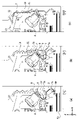
図11(a)および(b)は、排出トレイ13における満載検知の仕組みを説明するための図である。排出ローラ12から排出される記録媒体Sは、後端が排出ローラ12のニップ部から解放された後、重力によって可動トレイ950の上流側端部に寄せられ、後端が揃った状態で積載される。 11(a) and 11(b) are diagrams for explaining the mechanism for detecting the full load of the discharge tray 13. FIG. After the trailing edge of the recording medium S ejected from the ejecting roller 12 is released from the nip portion of the ejecting roller 12, the recording medium S is moved to the upstream end of the movable tray 950 by gravity and stacked with the trailing edge aligned. be.

排出ローラ12の鉛直上方には、回転軸30aを中心に回転可能なレバー30が配されている。レバー30は重力に従って図の反時計回りに回転しようとし、レバー30の先端が排出トレイ13に積載されている記録媒体の最上面に当接した位置で回転位置が決まる。すなわち、記録媒体の積載量が少ないときレバー30の先端は低い位置にあり、記録媒体の積載量が多くなるほどレバー30の先端は高い位置に移動する。レバー30の先端が、図のように積載された記録媒体に当接した状態で新たな記録媒体が排出されるとき、排出ローラ12のニップ部から排出される記録媒体Sの先端は、レバー30を押し上げてすでに積載されている記録媒体の上に積載される。 A lever 30 rotatable about a rotation shaft 30 a is arranged vertically above the discharge roller 12 . The lever 30 tends to rotate counterclockwise in the drawing according to gravity, and the rotational position is determined when the tip of the lever 30 contacts the uppermost surface of the recording media stacked on the discharge tray 13 . That is, the tip of the lever 30 is at a low position when the stacking amount of recording media is small, and the tip of the lever 30 moves to a higher position as the stacking quantity of recording media increases. When a new recording medium is ejected while the tip of the lever 30 is in contact with the stacked recording media as shown in the figure, the tip of the recording medium S ejected from the nip portion of the ejection roller 12 is is pushed up and loaded on top of the recording media already loaded.

レバー30の回転軸30aには、レバー30とともに回転する遮光板31が取り付けられている。また遮光板31の回転経路の一部には光学センサから成る満載検出センサ50が配されている。排出トレイ13にある記録媒体が少量のとき、レバー30の先端は低い位置にあり、満載検出センサ50は遮光板に遮断されていない。この状態において、搬送制御部207は、排出トレイ13は満載ではないと判断する。排出トレイ13に多数の記録媒体が排出されレバー30の先端位置が上昇し、満載検出センサが遮光板31によって遮断されると(図11(a))、搬送制御部207は排出トレイ13の満載を判断する。 A light shielding plate 31 that rotates together with the lever 30 is attached to the rotating shaft 30 a of the lever 30 . A full load detection sensor 50 consisting of an optical sensor is arranged in a part of the rotation path of the light blocking plate 31 . When the amount of recording media on the discharge tray 13 is small, the tip of the lever 30 is at a low position and the full load detection sensor 50 is not blocked by the light shielding plate. In this state, the transport control unit 207 determines that the discharge tray 13 is not fully loaded. When a large number of recording media are ejected onto the ejection tray 13, the tip position of the lever 30 is raised, and the full load detection sensor is blocked by the light shielding plate 31 (FIG. 11(a)), the transport control unit 207 detects that the ejection tray 13 is fully loaded. to judge.

一方、レバー30の鉛直方向下方には、レバー移動の駆動源となるレバー昇降部材1000によって回転可能な昇降部材40が配されている。昇降部材40は、図の時計回りに回転することによりレバー当接部32に当接し、レバー30を重力に逆らって押し上げ、レバー30の先端を積載された記録媒体から離すことができる(図11(b))。 On the other hand, below the lever 30 in the vertical direction, an elevating member 40 rotatable by a lever elevating member 1000 serving as a driving source for lever movement is arranged. When the lifting member 40 rotates clockwise in the figure, it comes into contact with the lever contact portion 32 and pushes up the lever 30 against the force of gravity so that the tip of the lever 30 can be separated from the loaded recording medium (FIG. 11). (b)).

以下、昇降部材40がレバー30を押し上げ、レバー30の先端が積載された記録媒体または可動トレイから退避した状態を「退避ポジション」と称す。また、昇降部材40がレバーと接触せず、レバー30の先端が積載された記録媒体に当接または当接可能な位置にあるポジションを「検知ポジション」と称す。すなわち、搬送制御部207は、レバー昇降部材1000を駆動することにより「検知ポジション」と「退避ポジション」を切り替えることができる。 Hereinafter, a state in which the lifting member 40 pushes up the lever 30 and the tip of the lever 30 is retracted from the stacked recording medium or movable tray is referred to as a "retraction position". Further, a position where the lifting member 40 does not contact the lever and the tip of the lever 30 contacts or can contact the stacked recording medium is referred to as a "detection position". That is, the transport control unit 207 can switch between the “detection position” and the “retreat position” by driving the lever lifting member 1000 .

本実施形態の記録装置1は、記録コマンドの内容に応じて「検知ポジション」と「退避ポジション」を切り替えるものとする。図12は、記録コマンドを受信したときに、プリントコントローラ202が実行する処理工程を説明するためのフローチャートである。 The recording apparatus 1 of this embodiment switches between the "detection position" and the "retraction position" according to the content of the recording command. FIG. 12 is a flowchart for explaining the processing steps performed by print controller 202 when a print command is received.

本処理が開始されると、プリントコントローラ202は、S1において、受信した記録コマンドに「仕分け排出処理」が設定されているか否かを判定する。ここで、「仕分け排出処理」とは、可動トレイ950を排出口に対し水平方向に移動させることにより、排出トレイ上の異なる位置に記録媒体を整列させるための排出処理を言う。「仕分け排出処理」が設定されている場合、S2に進み、レバー30が「退避ポジション」にあるか否かを判定する。 When this process is started, the print controller 202 determines in S1 whether or not "sorting discharge process" is set in the received print command. Here, "sorting and discharging processing" refers to discharging processing for aligning recording media at different positions on the discharging tray by horizontally moving the movable tray 950 with respect to the discharging port. When the "sorting and discharging process" is set, the process proceeds to S2 to determine whether or not the lever 30 is at the "retreat position".

S2において「退避ポジション」にある場合はS4に進み、「退避ポジション」にない場合は、S3でレバー昇降部材1000を駆動してレバー30を「退避ポジション」に移動させた後、S4に進む。 If it is in the "retracted position" in S2, the process proceeds to S4. If not in the "retracted position", in S3, the lever lifting member 1000 is driven to move the lever 30 to the "retracted position", and then the process proceeds to S4.

S4において、プリントコントローラ202は、「仕分け排出処理」を行いながら記録動作を実行する。すなわち、プリントコントローラ202は、搬送制御部207を介し、複数の記録媒体の排出タイミングに同期させながら可動トレイ950を幅方向に設けられた複数の排出位置に移動させる。これにより、排出口から排出される複数の記録媒体Sは、可動トレイ950上の複数の異なる位置に仕分けて積載される。一連の記録動作が終了するとS5に進み、プリントコントローラ202は、レバー30を「検出ポジション」に降下させる。 In S4, the print controller 202 executes the recording operation while performing the "sorting and discharging process". That is, the print controller 202 moves the movable tray 950 to a plurality of discharge positions provided in the width direction through the transport control unit 207 while synchronizing with the discharge timings of the plurality of recording media. As a result, a plurality of recording media S ejected from the ejection port are sorted and stacked at a plurality of different positions on the movable tray 950 . When a series of recording operations is completed, the process proceeds to S5, and the print controller 202 lowers the lever 30 to the "detection position".

例えば5枚セットのジョブを複数部出力する場合、可動トレイ950が第1の位置(リアまたはフロント)にある時に第1のセットが排出され、可動トレイ950が第2の位置(フロントまたはリア)にある時に第2のセットが排出される。また、第1のコマンドにより記録された記録媒体が第1の位置(リアまたはフロント)にある可動トレイ950に排出され、次に第2のコマンドが来たときは、可動トレイ950が第2の位置(フロントまたはリア)にある状態で記録媒体は排出される。 For example, when outputting multiple copies of a five-sheet set job, the first set is discharged when the movable tray 950 is at the first position (rear or front), and the movable tray 950 is at the second position (front or rear). A second set is ejected when . Also, the recording medium recorded by the first command is ejected to the movable tray 950 at the first position (rear or front), and when the second command comes next, the movable tray 950 is moved to the second position. The recording medium is ejected in the position (front or rear).

S6において、プリントコントローラ202は、排出トレイ13において記録媒体が満載か否かを判定する。すなわち、満載検出センサ50の出力に基づいて、満載検出センサ50が遮光板31に遮光されている場合は「満載」と判定し、遮光されていない場合は「満載ではない」と判定する。「満載ではない」と判定した場合、本処理は終了する。一方、「満載」と判定した場合、プリントコントローラ202はS7に進み、所定の満載処理を行った後、本処理を終了する。ここで、所定の満載処理とは、例えば操作パネル104を介して排出トレイ13が満載である旨をユーザに通知し、排出トレイ13から記録媒体を取り出すことを勧める処理である。 In S6, the print controller 202 determines whether or not the discharge tray 13 is full of recording media. That is, based on the output of the full load detection sensor 50, when the full load detection sensor 50 is shielded by the light shielding plate 31, it is determined as "full load", and when it is not shielded, it is determined as "not full load". If it is determined that the vehicle is not fully loaded, the process ends. On the other hand, if it is determined to be "fully loaded", the print controller 202 advances to S7, performs predetermined full loading processing, and then terminates this processing. Here, the predetermined full load process is, for example, a process of notifying the user via the operation panel 104 that the discharge tray 13 is full and recommending that the user take out recording media from the discharge tray 13 .

一方、S1において「仕分け排出処理」が設定されていないと判定した場合、プリントコントローラ202はS8に進み、レバー30が「検知ポジション」にあるか否かを判定する。 On the other hand, if it is determined in S1 that the "sorting and discharging process" is not set, the print controller 202 proceeds to S8 and determines whether or not the lever 30 is in the "detection position".

S8において「検知ポジション」にある場合はS10に進み、「検知ポジション」にない場合は、S9でレバー昇降部材1000を駆動してレバー30を「検知ポジション」に上昇させた後、S10に進む。 If it is in the "detection position" in S8, the process proceeds to S10, and if it is not in the "detection position" in S9, the lever lifting member 1000 is driven to raise the lever 30 to the "detection position", and then the process proceeds to S10.

S10において、プリントコントローラ202は、仕分けを含まない通常の排出処理を行いながら記録動作を実行する。すなわち、可動トレイを移動させること無く複数の記録媒体を排出する。これにより、連続的に排出される複数の記録媒体Sは、可動トレイ950の傾斜に沿って後端部が揃えられ、可動トレイ950上の同じ位置に積載される。 In S10, the print controller 202 executes a printing operation while performing normal discharge processing that does not include sorting. That is, a plurality of recording media are ejected without moving the movable tray. As a result, the plurality of recording media S that are continuously ejected are stacked at the same position on the movable tray 950 with their trailing ends aligned along the inclination of the movable tray 950 .

S10における記録動作の最中、プリントコントローラ202は、満載検出センサの出力値を検知する。積載された記録媒体に当接しているレバー30は排出トレイ13に積載されている記録媒体の枚数が増えるに連れて徐々に図の時計回りに回転する。そして、遮光板31が満載検出センサ50の位置に達すると、プリントコントローラ202は排出トレイ13が満載であると判定し、記録動作を停止し、所定の満載処理を実行した後、本処理を終了する。全ての記録動作が完了するまで満載が検出されない場合は、記録動作が完了した時点で本処理を終了する。 During the recording operation in S10, the print controller 202 detects the output value of the full load detection sensor. As the number of recording media stacked on the discharge tray 13 increases, the lever 30 in contact with the stacked recording media gradually rotates clockwise in the figure. When the light shielding plate 31 reaches the position of the full load detection sensor 50, the print controller 202 determines that the discharge tray 13 is full, stops the recording operation, executes predetermined full load processing, and then terminates this processing. do. If the full load is not detected until all the recording operations are completed, this process ends when the recording operations are completed.

以上説明した本実施形態によれば、記録コマンドに仕分けを伴う排出処理が設定されている場合、レバー30は排出トレイ13から退避され、その状態で可動トレイ950が幅方向に移動しながら複数の記録媒体が排出される。よって、排出トレイ13に積載されている複数の記録媒体は、レバー30に衝突することなく移動し、排出トレイ13の異なる複数の位置に整列する。一方、記録コマンドに仕分けを伴う排出処理が設定されていない場合、可動トレイ950が静止しレバー30が記録媒体に当接した状態で、複数の記録媒体が排出される。よって、排出トレイ13の同じ位置に複数の記録媒体が揃って積載される。このように本実施形態によれば、記録コマンドの内容に応じてレバー30の「検知ポジション」と「退避ポジション」を切り替えることにより、仕分けを伴う排出処理を正常に行いつつ排出トレイの満載を確実に検知することができる。また、積載された記録媒体の最上面とレバー先端とが接触したまま相対移動することを避けることができるため、積載された記録媒体のずれ、汚れ、傷等を防止することができる。 According to the present embodiment described above, when the ejection process accompanied by sorting is set in the recording command, the lever 30 is retracted from the ejection tray 13, and in this state, the movable tray 950 moves in the width direction to produce a plurality of images. The recording medium is ejected. Therefore, a plurality of recording media stacked on the ejection tray 13 move without colliding with the lever 30 and are aligned at a plurality of different positions on the ejection tray 13 . On the other hand, when ejection processing accompanied by sorting is not set in the recording command, a plurality of recording media are ejected with the movable tray 950 stationary and the lever 30 in contact with the recording media. Therefore, a plurality of recording media are stacked at the same position on the discharge tray 13 . As described above, according to the present embodiment, by switching the lever 30 between the "detection position" and the "retraction position" according to the content of the recording command, the discharge process accompanied by the sorting can be normally performed while ensuring that the discharge tray is fully loaded. can be detected. In addition, since the uppermost surface of the stacked recording medium and the tip of the lever can be prevented from moving relative to each other while being in contact with each other, the stacked recording medium can be prevented from being displaced, soiled, damaged, and the like.

(第2の実施形態)
本実施形態においても、第1の実施形態と同様の記録装置1を用いる。本実施形態の記録装置1では、可動トレイ950の幅方向の移動位置を正確に管理するため、適切なタイミングで可動トレイ950の原点位置を取得する初期化動作を行う。本実施形態では第1の初期化動作と第2の初期化動作を用意する。
(Second embodiment)
Also in this embodiment, the same recording apparatus 1 as in the first embodiment is used. In the recording apparatus 1 of the present embodiment, in order to accurately manage the movement position of the movable tray 950 in the width direction, an initialization operation for acquiring the origin position of the movable tray 950 is performed at appropriate timing. In this embodiment, a first initialization operation and a second initialization operation are prepared.

第1の初期化動作は、スタンバイ状態にある記録装置1に新たな記録コマンドが入力された場合など、比較的短時間の非稼働時間の後に記録動作が開始される場合に行うものである。スタンバイ状態ではただちに記録動作を開始することが求められるため、第1の初期化動作は、比較的短い所要時間で可動トレイ950の原点位置を取得することが必要である。 The first initialization operation is performed when a recording operation is started after a relatively short period of non-operation, such as when a new recording command is input to the recording apparatus 1 in the standby state. Since it is required to start the recording operation immediately in the standby state, the first initialization operation needs to acquire the origin position of the movable tray 950 in a relatively short required time.

一方、第2の初期化動作は、電源ON時や、スリープ状態にあるときに記録コマンドが入力された場合など、比較的長時間の非稼働時間の後に記録動作が開始される場合に行うものである。非稼働時間が長時間に及ぶと可動トレイ950の移動経路になんらかの異物が置かれる可能性が高くなる。また、非稼働時間が長時間に及ぶと、コギング変動等によってトレイ用モータ990が回転したり、外力等の外乱が作用したりするなどして可動トレイが動いてしまう場合もある。このため、第2の初期化動作は、原点位置の取得に加え、可動トレイ950の移動領域全域において、正常に移動可能か否かの検査も行う。 On the other hand, the second initialization operation is performed when the recording operation is started after a relatively long period of non-operating time, such as when the power is turned on or when a recording command is input in the sleep state. is. If the non-operating time is long, there is a high possibility that some kind of foreign object will be placed on the moving path of the movable tray 950 . Further, if the non-operating time is long, the tray motor 990 may rotate due to cogging fluctuation or the like, or the movable tray may move due to disturbance such as external force. Therefore, in the second initialization operation, in addition to acquiring the origin position, it is also inspected whether or not the movable tray 950 can move normally in the entire movement area.

図13(a)~(c)は、可動トレイ950を移動させるための構成および原点位置の取得方法を説明するための図である。図13(a)は、図10で示した駆動伝達ユニット60の拡大図である。DCモータであるトレイ用モータ990の駆動力は、プーリ61およびアイドラプーリ62を介してエンドレスベルト63を回動させる。エンドレスベルト63の直線部分には、可動トレイ950の背面と連結する可動トレイ連結部66が取り付けられている。このような構成の下、搬送制御部207が、トレイ用モータ990を正方向および逆方向に駆動することにより、可動トレイ連結部66に連結された可動トレイ950が、幅方向(図の±y方向)に往復に移動する。 FIGS. 13A to 13C are diagrams for explaining the configuration for moving the movable tray 950 and the method for obtaining the origin position. FIG. 13(a) is an enlarged view of the drive transmission unit 60 shown in FIG. The driving force of the tray motor 990 , which is a DC motor, rotates the endless belt 63 via the pulley 61 and the idler pulley 62 . A movable tray connecting portion 66 that connects with the rear surface of the movable tray 950 is attached to the linear portion of the endless belt 63 . Under this configuration, the transport control unit 207 drives the tray motor 990 in the forward and reverse directions, thereby moving the movable tray 950 connected to the movable tray connecting unit 66 in the width direction (±y in the figure). direction).

可動トレイ連結部66の移動可能領域の両端部であって、可動トレイ連結部66が突き当て可能な位置には、第1基準突き当て64と第2基準突き当て65が配されている。本実施形態では、可動トレイ連結部66が第1基準突き当て64に突き当る位置を、可動トレイ950の原点位置とする。 A first reference abutment 64 and a second reference abutment 65 are arranged at both ends of the movable area of the movable tray connecting portion 66 and at positions where the movable tray connecting portion 66 can abut. In the present embodiment, the position where the movable tray connecting portion 66 hits the first reference abutment 64 is the origin position of the movable tray 950 .

トレイ用モータ990の駆動中に可動トレイ連結部66が第1基準突き当て64または第2基準突き当て65に突き当たると、トレイ用モータ990の負荷が上昇する。また、可動トレイ950の移動経路中になんらかの異物が存在する場合も、トレイ用モータ990の負荷は上昇する。本実施形態では、このようなトレイ用モータ990の負荷を検出することにより、可動トレイ950の原点位置を把握したり異物の存在を検出したりする。なお、トレイ用モータの負荷は、トルク、電流値、単位時間当たりの移動量などから計測することができる。 When the movable tray connecting portion 66 hits the first reference abutment 64 or the second reference abutment 65 while the tray motor 990 is being driven, the load of the tray motor 990 increases. In addition, the load on the tray motor 990 also increases when some kind of foreign matter exists in the moving path of the movable tray 950 . In this embodiment, by detecting the load of the tray motor 990, the origin position of the movable tray 950 can be grasped and the presence of a foreign object can be detected. The load of the tray motor can be measured from the torque, current value, movement amount per unit time, and the like.

図13(b)に示すように、トレイ用モータ990には、トレイ用モータ990と同軸に回転するコードホイール70が取り付けられ、コードホイール70の規則的なマーキングをエンコーダセンサ71が検出する。従って、プリントコントローラ202は、エンコーダセンサ71がマーキングを検出した回数をカウントすることにより、コードホイール70の回転量、すなわち可動トレイ950の相対移動量を検出することができる。 As shown in FIG. 13B, the tray motor 990 is attached with a code wheel 70 that rotates coaxially with the tray motor 990 , and an encoder sensor 71 detects regular markings on the code wheel 70 . Therefore, the print controller 202 can detect the amount of rotation of the code wheel 70, that is, the amount of relative movement of the movable tray 950, by counting the number of times the encoder sensor 71 detects the marking.

図13(c)は、相対移動量に対するトレイ用モータ990の負荷の様子を示すグラフである。トレイ用モータ990の駆動中に可動トレイ連結部66が第1基準突き当て64または第2基準突き当て65に突き当たると、図に示すようにトレイ用モータ990の負荷が上昇し、閾値を超える。 FIG. 13(c) is a graph showing the load of the tray motor 990 with respect to the amount of relative movement. When the movable tray connecting portion 66 hits the first reference abutment 64 or the second reference abutment 65 while the tray motor 990 is being driven, the load of the tray motor 990 rises and exceeds the threshold as shown in the figure.

以上の構成のもと、プリントコントローラ202は、可動トレイ連結部66が第1基準突き当て64に向かうようにトレイ用モータ990を駆動しながらモータ負荷を検知する。そして、モータ負荷が閾値を超えた位置を例えば原点位置(すなわちマーキングカウント値を0)と定義する。そして、原点位置が定義された後は、原点からのカウント値に基づいて可動トレイ950の絶対位置を制御する。 With the above configuration, the print controller 202 detects the motor load while driving the tray motor 990 so that the movable tray connecting portion 66 faces the first reference abutment 64 . Then, the position where the motor load exceeds the threshold value is defined as, for example, the origin position (that is, the marking count value is 0). After the origin position is defined, the absolute position of the movable tray 950 is controlled based on the count value from the origin.

ところで、以上のような初期化動作においても、レバー30が「検知ポジション」にあると、レバー30が排出トレイに載せられた紙束などに衝突し、原点位置を正確に取得できないおそれが生じる。よって、本実施形態では、初期化動作を行う場合にも当該動作に先立ってレバー30を退避ポジションに移動させる。 By the way, even in the initialization operation as described above, if the lever 30 is at the "detection position", the lever 30 may collide with a stack of paper placed on the discharge tray, and the origin position may not be obtained accurately. Therefore, in this embodiment, even when performing the initialization operation, the lever 30 is moved to the retracted position prior to the initialization operation.

図14は、第1の初期化動作の工程を説明するためのフローチャートである。本処理は、スタンバイ状態にある記録装置1が記録コマンドを受信したときに、プリントコントローラ202が記録動作に先立って実行する処理である。 FIG. 14 is a flow chart for explaining the steps of the first initialization operation. This process is executed by the print controller 202 prior to the printing operation when the printing apparatus 1 in the standby state receives a print command.

本処理が開始されると、プリントコントローラ202は、S11においてレバー30が「退避ポジション」にあるか否かを判定する。「退避ポジション」にある場合はS13に進む。S11において「退避ポジション」にない場合はS12に進み、レバー昇降部材1000を駆動してレバー30を「退避ポジション」まで上昇させた後、S13に進む。 When this process is started, the print controller 202 determines whether or not the lever 30 is at the "retreat position" in S11. If it is in the "retreat position", proceed to S13. If it is not in the "retracted position" in S11, the process proceeds to S12, and after driving the lever elevating member 1000 to raise the lever 30 to the "retracted position", the process proceeds to S13.

S13において、プリントコントローラ202は、トレイ用モータ990を駆動して、可動トレイ950を第1基準突き当て64の方向(-y方向)に移動させながら、トレイ用モータ990の負荷を検知する。この際、プリントコントローラ202は、突き当てに伴う破損を防ぐため、実際に「仕分け排出処理」を行う場合よりも遅い速度(100mm/s以下)で可動トレイ950を移動させる。このような移動は、S14でモータ負荷が閾値を超えたと判定されるまで継続する。 In S13, the print controller 202 drives the tray motor 990 to detect the load of the tray motor 990 while moving the movable tray 950 in the direction of the first reference abutment 64 (-y direction). At this time, the print controller 202 moves the movable tray 950 at a slower speed (100 mm/s or less) than when the "sorting and discharging process" is actually performed in order to prevent damage due to bumping. Such movement continues until it is determined in S14 that the motor load exceeds the threshold.

S14でモータ負荷が閾値を超えたと判定されるとS15進み、プリントコントローラ202は原点処理を実行する。具体的には、マーキングのカウント値を0にリセットする。 If it is determined in S14 that the motor load has exceeded the threshold value, the process proceeds to S15, and the print controller 202 executes origin processing. Specifically, the marking count value is reset to zero.

S16において、プリントコントローラ202は、トレイ用モータ990を駆動して、可動トレイ950を第2基準突き当ての方向に、予め設定された初期位置まで移動させる。本実施形態において、初期位置とは原点位置(第1基準突き当て64の位置)から僅かに第2基準突き当て65の方向に移動した位置とする。原点位置から初期位置までの距離(カウント量)は予め記憶されており、プリントコントローラ202は、カウント値が当該所定のカウント量に達するまで可動トレイ950を移動させる。 In S16, the print controller 202 drives the tray motor 990 to move the movable tray 950 to the preset initial position in the direction of the second reference abutment. In this embodiment, the initial position is a position slightly moved in the direction of the second reference abutment 65 from the origin position (the position of the first reference abutment 64). The distance (count amount) from the origin position to the initial position is stored in advance, and the print controller 202 moves the movable tray 950 until the count value reaches the predetermined count amount.

S17において、プリントコントローラ202は、レバー昇降部材1000を駆動し、レバー30を「検知ポジション」まで降下させる。以上で本処理を終了する。以上のような第1の初期化動作は、可動領域全域において可動トレイ950を移動させる必要がないため、比較的短い所要時間で終了させ記録動作に移行することができる。 In S17, the print controller 202 drives the lever lifting member 1000 to lower the lever 30 to the "detection position". This completes the processing. Since the first initialization operation as described above does not need to move the movable tray 950 over the entire movable area, it can be completed in a relatively short required time and the recording operation can be started.

第1の初期化動作の後、プリントコントローラは図12で説明したフローチャートに従って、記録動作を実行すればよい。この際、S4の記録動作において、プリントコントローラ202は、複数の記録媒体の排出タイミングに同期させながら、上記第1の初期化動作で取得した原点位置を基準とした複数の位置に可動トレイ950を移動させることになる。これにより、連続的に排出される複数の記録媒体Sを、複数の異なる位置に所定枚数ずつ整列して積載させることができる。 After the first initialization operation, the print controller should perform the recording operation according to the flowchart described in FIG. At this time, in the recording operation of S4, the print controller 202 moves the movable tray 950 to a plurality of positions based on the origin position obtained in the first initialization operation while synchronizing with the ejection timing of the plurality of recording media. will be moved. As a result, a plurality of recording media S that are continuously ejected can be stacked in a predetermined number of sheets at a plurality of different positions.

なお、同じ原点位置のまま可動トレイ950の移動を何度も繰り返していると、エンコーダのカウント値と可動トレイの絶対位置との僅かな誤差が累積し、可動トレイ950の位置を正確に管理できなくなる場合がある。このような場合には、記録コマンドを受信したときの記録装置1がスタンバイ状態になくても、累積誤差が許容値を超える程度のタイミングで上記第1の初期化動作を行って原点位置を更新することが好ましい。 If the movement of the movable tray 950 is repeated many times while maintaining the same origin position, a slight error between the count value of the encoder and the absolute position of the movable tray accumulates, and the position of the movable tray 950 cannot be accurately managed. may disappear. In such a case, even if the recording apparatus 1 is not in the standby state when the recording command is received, the first initialization operation is performed at the timing when the accumulated error exceeds the allowable value to update the origin position. preferably.

次に、第2の初期化動作について説明する。図15は、第2の初期化動作の工程を説明するためのフローチャートである。本処理は、記録装置1に電力が投入(電源ON)されたときや、スリープ状態にあるタイミングで記録コマンドを受信したときに、記録動作に先立ってプリントコントローラ202が実行する処理である。 Next, the second initialization operation will be explained. FIG. 15 is a flow chart for explaining the process of the second initialization operation. This process is executed by the print controller 202 prior to the printing operation when power is supplied to the printing apparatus 1 (power ON) or when a print command is received in the sleep state.

本処理が開始されると、プリントコントローラ202は、S21においてレバー30が「退避ポジション」にあるか否かを判定する。「退避ポジション」にある場合はS23に進む。S21において「退避ポジション」にない場合は、S22でレバー昇降部材1000を駆動してレバー30を「退避ポジション」まで移動させた後、S23に進む。 When this process is started, the print controller 202 determines whether or not the lever 30 is at the "retreat position" in S21. If it is in the "retreat position", proceed to S23. If it is not in the "retracted position" in S21, the lever lifting member 1000 is driven to move the lever 30 to the "retracted position" in S22, and then the process proceeds to S23.

S23において、プリントコントローラ202は、トレイ用モータ990を駆動して、可動トレイ950を第2基準突き当て65の方向(+y方向)に移動させながら、トレイ用モータ990の負荷を検知する。この際、プリントコントローラ202は、実際に「仕分け排出処理」を行う場合よりも遅い速度(100mm/s以下)で可動トレイ950が移動するように、トレイ用モータ990を駆動する。このような移動は、S24でモータ負荷が閾値を超えたと判定されるまで継続する。 In S23, the print controller 202 detects the load of the tray motor 990 while driving the tray motor 990 to move the movable tray 950 in the direction of the second reference abutment 65 (+y direction). At this time, the print controller 202 drives the tray motor 990 so that the movable tray 950 moves at a slower speed (100 mm/s or less) than when the "sorting and discharging process" is actually performed. Such movement continues until it is determined in S24 that the motor load exceeds the threshold.

S24でモータ負荷が閾値を超えたと判定されるとS25進み、プリントコントローラ202は、第2基準位置を取得する。具体的には、マーキングの現在のカウント値C2を記憶する。S24でモータ負荷が閾値を超えた原因が、第2基準突き当て65との当接でなく何かしらの異物との衝突であったとしても、S25ではその異物の位置を第2基準位置として保存する。 If it is determined in S24 that the motor load has exceeded the threshold, the print controller 202 proceeds to S25 and acquires the second reference position. Specifically, the current count value C2 of marking is stored. Even if the cause of the motor load exceeding the threshold in S24 is not the contact with the second reference abutment 65 but the collision with some foreign matter, the position of the foreign matter is saved as the second reference position in S25. .

S26において、プリントコントローラ202は、トレイ用モータ990を駆動して、可動トレイ950を第1基準突き当て64の方向(-y方向)に移動させながら、トレイ用モータ990の負荷を検知する。S26においても、S23と同様、可動トレイ950は低速度で移動させる。 In S26, the print controller 202 drives the tray motor 990 to detect the load of the tray motor 990 while moving the movable tray 950 in the direction of the first reference abutment 64 (-y direction). Also in S26, the movable tray 950 is moved at a low speed as in S23.

S27でモータ負荷が閾値を超えたと判定すると、プリントコントローラ202は、第1基準位置を取得する(S28)。具体的には、マーキングの現在のカウント値C1を記憶する。 If it is determined in S27 that the motor load has exceeded the threshold, the print controller 202 acquires the first reference position (S28). Specifically, the current count value C1 of the marking is stored.

S29において、プリントコントローラ202は、第2基準位置から第1基準位置までのカウント量D(=C1-C2)を算出する。このようなカウント量DはS28で検出した第1基準位置とS24で検出した第2基準位置の距離に対応する。 In S29, the print controller 202 calculates the count amount D (=C1-C2) from the second reference position to the first reference position. Such count amount D corresponds to the distance between the first reference position detected in S28 and the second reference position detected in S24.

S30において、プリントコントローラ202は、カウント量Dが予め定めた上限閾値と下限閾値の間にあるか否かを判定する。カウント量Dが上限値と下限値の間に含まれない場合は、本来の第1基準突き当て64と第2基準突き当て65の間に何らかの異物が存在したり、トレイ用モータ990の回転量をエンコーダセンサ71が正確に検知できていなかったりしていることが想定される。よって、プリントコントローラ202はS33に進み、所定のエラー処理を行って本処理を終了する。所定のエラー処理とは、例えば、操作パネル104などを介して、排出トレイ13に異常が発生した旨をユーザに通知し、異物の確認などを勧める処理である。 In S30, the print controller 202 determines whether or not the count amount D is between a predetermined upper threshold and lower threshold. If the count amount D is not included between the upper limit value and the lower limit value, there is some foreign matter between the original first reference abutment 64 and the second reference abutment 65, or the amount of rotation of the tray motor 990 is changed. It is assumed that the encoder sensor 71 is not able to detect accurately. Therefore, the print controller 202 advances to S33, performs predetermined error processing, and terminates this processing. The predetermined error process is, for example, a process of notifying the user that an abnormality has occurred in the output tray 13 via the operation panel 104 or the like and recommending confirmation of foreign matter.

一方、S30において、カウント量Dが上限閾値と下限閾値の間にあると判定した場合、プリントコントローラ202はS31に進み、第1基準位置を原点に設定した上で、可動トレイ950を初期位置まで移動する。具体的には、第1基準位置においてのマーキングのカウント値をリセット(0に設定)する。そして、再びトレイ用モータ990を駆動して、可動トレイ950を第2基準突き当て65の方向に初期位置まで移動させる。 On the other hand, if it is determined in S30 that the count amount D is between the upper limit threshold value and the lower limit threshold value, the print controller 202 advances to S31, sets the first reference position as the origin, and moves the movable tray 950 to the initial position. Moving. Specifically, the marking count value at the first reference position is reset (set to 0). Then, the tray motor 990 is driven again to move the movable tray 950 to the initial position in the direction of the second reference abutment 65 .

S32において、プリントコントローラ202は、レバー昇降部材1000を駆動し、レバー30を「検知ポジション」まで降下させる。以上で本処理を終了する。以上のような第2の初期化動作は、所要時間が多少かかるが、可動トレイ950の可動領域全域を検査することができるため、その後行われる排出トレイの水平方向への移動を伴う動作の確実性を高めことができる。 In S32, the print controller 202 drives the lever lifting member 1000 to lower the lever 30 to the "detection position". This completes the processing. Although the second initialization operation as described above takes some time, it can inspect the entire movable area of the movable tray 950, so that the subsequent operation accompanying the horizontal movement of the discharge tray can be performed reliably. can enhance sexuality.

なお、図15のフローチャートでは、第2の基準位置を取得してから第1の基準位置を取得する順番としたが、この順番は逆転させても良い。 In addition, in the flowchart of FIG. 15, the order of obtaining the first reference position after obtaining the second reference position is set, but this order may be reversed.

以上説明した本実施形態によれば、第1の初期化動作においても第2の初期化動作においても、レバー30を「退避ポジション」に退避させた後に、原点位置の取得や移動経路の検査を行っている。よって、初期化動作を確実に行い、その後行われる「仕分け排出処理」の信頼性を高めることができる。 According to the present embodiment described above, in both the first initialization operation and the second initialization operation, after the lever 30 is retracted to the "retreat position", acquisition of the origin position and inspection of the movement path are performed. Is going. Therefore, the initialization operation can be reliably performed, and the reliability of the subsequent "sorting and discharging process" can be enhanced.

なお、以上では、可動トレイ連結部66を基準突き当てに突き当てた際のモータ負荷を検出することによって原点位置を取得したが、本発明はこのような形態に限定されるものではない。例えば、基準となる位置に光学センサを設け、可動トレイ950に取り付けた遮光板が光学センサを遮光したタイミングで原点位置を取得するようにしてもよい。基準位置や異物を検出できる仕組みであれば、このような光学的手法のほか、電気的手法や磁気的手法などを採用することもできる。 In the above description, the origin position is acquired by detecting the motor load when the movable tray connecting portion 66 is abutted against the reference abutment, but the present invention is not limited to such a form. For example, an optical sensor may be provided at a reference position, and the origin position may be obtained at the timing when the light shielding plate attached to the movable tray 950 blocks light from the optical sensor. In addition to such optical techniques, electrical techniques, magnetic techniques, and the like can be employed as long as they are mechanisms capable of detecting the reference position and foreign matter.

以上では第1と第2の2つの初期化動作について説明したが、更に別の初期化動作を用意しても良い。また、以上では原点位置と初期位置とを別に設けたが、原点位置を初期位置としても良い。この場合、原点処理を行った後に初期位置まで移動する工程を省略することができる。 Although the first and second initialization operations have been described above, another initialization operation may be prepared. Moreover, although the origin position and the initial position are provided separately above, the origin position may be used as the initial position. In this case, it is possible to omit the step of moving to the initial position after performing the origin processing.

(その他の実施形態)
本発明は、上述した第1の実施形態や第2の実施形態のように記録動作や初期化動作の直前にレバー30を退避させることに限定されるものではない。可動トレイ950の移動を伴う動作が行われる際に、その動作に先立ってレバーが退避ポジションに移動されればよい。この際、レバー30を退避ポジションに移動させるタイミングは、上記動作の直前だけでなく記録装置が非稼動となる直前(例えば排出完了直後、電源オフ直前、スリープ状態移行直前)であってもよい。いずれにせよ、「仕分け排出処理」が可能な画像記録装置であって、可動トレイ950の移動を伴う動作を、レバー30が退避ポジションにあることを確認した上で行う構成であれば、本発明の範疇である。
(Other embodiments)
The present invention is not limited to retracting the lever 30 immediately before the recording operation or initialization operation as in the first and second embodiments described above. When an operation involving movement of the movable tray 950 is performed, the lever may be moved to the retracted position prior to the operation. At this time, the timing of moving the lever 30 to the retracted position may be not only immediately before the operation described above but also immediately before the printing apparatus becomes non-operational (for example, immediately after ejection is completed, immediately before power is turned off, immediately before transition to sleep state). In any case, as long as the image recording apparatus is capable of the "sorting and discharging process" and is configured to perform the operation involving the movement of the movable tray 950 after confirming that the lever 30 is at the retracted position, the present invention can be applied. It is the category of

1 インクジェット記録装置(画像記録装置)
8 記録ヘッド
30 レバー
40 昇降部材
202 プリントコントローラ
207 搬送制御部
950 可動トレイ
990 トレイ用モータ
991 駆動伝達ユニット
1000 レバー昇降部材
1 Inkjet recording device (image recording device)
8 recording head 30 lever 40 elevation member 202 print controller 207 transport control unit 950 movable tray 990 tray motor 991 drive transmission unit 1000 lever elevation member

Claims (17)

記録媒体に画像を記録する記録手段と、
前記記録手段によって記録を行うための印刷ジョブを受信する受信手段と、
前記記録手段によって画像が記録され第1の方向に排出される記録媒体を積載するためのトレイを、前記第1の方向と交差する第2の方向に移動させるトレイ移動手段と、
前記トレイに積載された記録媒体に当接し積載量に応じて移動可能な当接部材を、前記積載された記録媒体に当接することが可能な第1ポジションと、前記積載された記録媒体から離間された第2ポジションと、の間で移動させる当接部材移動手段と、
前記トレイ移動手段および前記当接部材移動手段を制御する制御手段と、
を備える画像記録装置であって、
前記制御手段は、記録媒体を前記トレイに排出する際に、前記当接部材移動手段を制御して前記当接部材が前記第1ポジションにある状態にし、前記トレイ移動手段に前記トレイを前記第2の方向に移動させない第1のモードと、前記当接部材移動手段を制御して前記受信手段が受信した前記印刷ジョブの記録の開始から終了までの間前記当接部材が前記第2ポジションにある状態にし、記録媒体の排出に応じて前記トレイ移動手段に前記トレイを前記第2の方向に移動させる第2のモードと、を実行することが可能であることを特徴とする画像記録装置。
a recording means for recording an image on a recording medium;
receiving means for receiving a print job for recording by the recording means;
tray moving means for moving, in a second direction intersecting the first direction, a tray for stacking recording media on which an image is recorded by the recording means and ejected in a first direction;
A contact member that contacts the recording media stacked on the tray and is movable according to the stacking amount is separated from a first position capable of contacting the stacked recording media and from the stacked recording media. and a contact member moving means for moving between the second position;
a control means for controlling the tray moving means and the contact member moving means;
An image recording device comprising:
The control means controls the contact member moving means to put the contact member in the first position when the recording medium is discharged to the tray, and the tray moving means moves the tray to the first position. a first mode in which the contact member is not moved in the direction 2; and a second mode in which the tray moving means moves the tray in the second direction in accordance with ejection of the recording medium.
前記第1ポジションにあって前記積載された記録媒体に当接している前記当接部材の位置に基づいて、前記トレイにおける前記記録媒体の満載を検出する満載検出手段を更に備え、
前記満載検出手段が満載を検出した場合、前記制御手段は前記記録手段に記録動作を停止させることを特徴とする請求項1に記載の画像記録装置。
Further comprising full load detection means for detecting full loading of the recording medium in the tray based on the position of the contact member that is in the first position and is in contact with the stacked recording medium,
2. An image recording apparatus according to claim 1, wherein said control means causes said recording means to stop recording when said full load detection means detects a full load.
前記第2のモードにおいて、前記制御手段は、前記記録手段に画像を記録させながら、前記トレイ移動手段に、前記記録手段によって画像が記録された記録媒体の排出に同期して前記トレイを前記第2の方向に移動させることを特徴とする請求項1または2に記載の画像記録装置。 In the second mode, while causing the recording means to record an image, the control means causes the tray moving means to move the tray to the second position in synchronism with ejection of the recording medium on which the image has been recorded by the recording means. 3. The image recording apparatus according to claim 1, wherein the image recording apparatus moves in two directions. 前記第2のモードにおいて、前記制御手段は、前記トレイの移動が完了し、移動した位置にある前記トレイへの記録媒体の排出が完了した後、前記当接部材移動手段に前記当接部材を前記第2ポジションから前記第1ポジションに移動させることを特徴とする請求項1から3のいずれか1項に記載の画像記録装置。 In the second mode, after the movement of the tray is completed and the ejection of the recording medium to the tray at the moved position is completed, the control means moves the contact member to the contact member moving means. 4. The image recording apparatus according to any one of claims 1 to 3, wherein the is moved from the second position to the first position. 前記制御手段は、前記トレイ移動手段に前記トレイを前記第2の方向に移動させることにより、移動領域の原点位置を取得するための初期化動作を行うことを特徴とする請求項1から4のいずれか1項に記載の画像記録装置。 5. The apparatus according to any one of claims 1 to 4, wherein said control means performs an initialization operation for obtaining an origin position of a moving area by causing said tray moving means to move said tray in said second direction. The image recording apparatus according to any one of items 1 and 2. 前記初期化動作は、前記トレイが前記移動領域のうち一部の領域を移動する第1の初期化動作と、前記トレイが前記移動領域の全ての領域を移動する第2の初期化動作とを有することを特徴とする請求項5に記載の画像記録装置。 The initialization operation includes a first initialization operation in which the tray moves in a part of the movement area, and a second initialization operation in which the tray moves in the entire movement area. 6. The image recording apparatus according to claim 5, characterized by comprising: 前記記録手段は、前記トレイの鉛直下方に配され、画像データに従ってインクを吐出するフルラインタイプのインクジェット記録ヘッドであることを特徴とする請求項1から6のいずれか1項に記載の画像記録装置。 7. The image recording apparatus according to claim 1, wherein said recording means is a full-line type ink jet recording head which is disposed vertically below said tray and ejects ink according to image data. Device. 前記当接部材は、前記トレイに積載された記録媒体に当接し積載量に応じて回転可能なことを特徴とする請求項1から7のいずれか1項に記載の画像記録装置。 8. The image recording apparatus according to any one of claims 1 to 7, wherein the contact member contacts the recording medium stacked on the tray and is rotatable according to the amount of the recording medium loaded. 記録媒体を前記トレイに排出する排出手段をさらに備えることを特徴とする請求項1から8のいずれか1項に記載の画像記録装置。 9. The image recording apparatus according to any one of claims 1 to 8, further comprising ejecting means for ejecting a recording medium to said tray. 記録媒体に画像を記録する記録手段と、
前記記録手段によって記録を行うための印刷ジョブを受信する受信手段と、
前記記録手段によって画像が記録され第1の方向に排出される記録媒体を積載するためのトレイと、
前記トレイに積載された記録媒体に当接し、積載量に応じて移動可能な当接部材と、
を備える画像記録装置の制御方法であって、
記録媒体を前記トレイに排出する際に、前記当接部材が前記積載された記録媒体に当接することが可能な第1ポジションにある状態にし、前記トレイを前記第1の方向と交差する第2の方向に移動させない第1のモードと、
前記受信手段が受信した前記印刷ジョブの記録の開始から終了までの間、前記当接部材が前記積載された記録媒体から離間された第2ポジションにある状態にし、記録媒体の排出に応じて前記トレイを前記第2の方向に移動させる第2のモードと、
を実行することが可能であることを特徴とする制御方法。
a recording means for recording an image on a recording medium;
receiving means for receiving a print job for recording by the recording means;
a tray for stacking a recording medium on which an image is recorded by the recording means and ejected in a first direction;
a contact member that contacts the recording media stacked on the tray and is movable according to the stacking amount;
A control method for an image recording device comprising
When the recording medium is ejected to the tray, the contact member is placed in a first position in which the contact member can contact the stacked recording medium, and the tray is placed in a second direction intersecting the first direction. a first mode that does not move in the direction of
During the period from the start to the end of recording of the print job received by the receiving means, the abutment member is placed in a second position separated from the stacked recording medium, and the recording medium is ejected. a second mode for moving the tray in the second direction;
A control method characterized in that it is possible to execute
前記第1ポジションにあって前記積載された記録媒体に当接している前記当接部材の位置に基づいて、前記トレイにおける前記記録媒体の満載を検出する満載検出工程を有し、前記満載検出工程で満載を検出した場合、前記記録手段に記録動作を停止させることを特徴とする請求項10に記載の制御方法。 a full load detection step of detecting a full load of the recording media in the tray based on the position of the contact member that is in the first position and is in contact with the stacked recording media; 11. The control method according to claim 10, further comprising the step of causing said recording means to stop recording operation when full loading is detected by said recording means. 前記第2のモードでは、前記記録手段によって画像が記録された記録媒体の排出に同期して前記トレイを前記第2の方向に移動させることを特徴とする請求項10または11に記載の制御方法。 12. The control method according to claim 10, wherein, in said second mode, said tray is moved in said second direction in synchronization with ejection of a recording medium on which an image has been recorded by said recording means. . 前記第2のモードでは、前記トレイの移動が完了し、移動した位置にある前記トレイへの記録媒体の排出が完了した後、前記当接部材を前記第2ポジションから前記第1ポジションに移動させることを特徴とする請求項10から12のいずれか1項に記載の制御方法。 In the second mode, the contact member is moved from the second position to the first position after the movement of the tray is completed and the ejection of the recording medium to the tray at the moved position is completed . 13. The control method according to any one of claims 10 to 12, characterized in that 前記トレイを前記第2の方向に移動させることにより、移動領域の原点位置を取得するための初期化動作を行うことを特徴とする請求項10から13のいずれか1項に記載の制御方法。 14. The control method according to any one of claims 10 to 13, wherein by moving the tray in the second direction, an initialization operation for obtaining the origin position of the movement area is performed. 前記初期化動作は、前記トレイが前記移動領域のうち一部の領域を移動する第1の初期化動作と、前記トレイが前記移動領域の全ての領域を移動する第2の初期化動作を有することを特徴とする請求項14に記載の制御方法。 The initialization operation includes a first initialization operation in which the tray moves in a part of the movement area, and a second initialization operation in which the tray moves in the entire movement area. 15. The control method according to claim 14, characterized by: 前記当接部材は、前記トレイに積載された記録媒体に当接し積載量に応じて回転可能なことを特徴とする請求項10から15のいずれか1項に記載の制御方法。 16. The control method according to any one of claims 10 to 15, wherein the contact member contacts the recording media stacked on the tray and is rotatable according to the amount of the recording media loaded. ジョブを受信する受信手段と、
画像が記録され第1の方向に排出される記録媒体を積載するためのトレイを、前記第1の方向と交差する第2の方向に移動させるトレイ移動手段と、
前記トレイに積載された記録媒体に当接し積載量に応じて回転可能な当接部材を、前記積載された記録媒体に当接することが可能な第1ポジションと、前記積載された記録媒体から離間された第2ポジションと、の間で移動させる当接部材移動手段と、
前記トレイ移動手段および前記当接部材移動手段を制御する制御手段と、
を備える記録媒体排出装置であって、
前記制御手段は、記録媒体を前記トレイに排出する際に、前記当接部材移動手段を制御して前記当接部材が前記第1ポジションにある状態にし、前記トレイ移動手段に前記トレイを前記第2の方向に移動させない第1のモードと、前記当接部材移動手段を制御して前記受信手段が受信した前記ジョブの開始から終了までの間前記当接部材が前記第2ポジションにある状態にし、記録媒体の排出に応じて前記トレイ移動手段に前記トレイを前記第2の方向に移動させる第2のモードと、を実行することが可能であることを特徴とする記録媒体排出装置。
a receiving means for receiving a job;
tray moving means for moving, in a second direction intersecting the first direction, a tray for stacking recording media on which an image is recorded and ejected in a first direction;
A contact member that contacts the recording media stacked on the tray and is rotatable according to the stacking amount is moved to a first position capable of contacting the stacked recording media and away from the stacked recording media. and a contact member moving means for moving between the second position;
a control means for controlling the tray moving means and the contact member moving means;
A recording medium ejection device comprising
The control means controls the contact member moving means to put the contact member in the first position when the recording medium is discharged to the tray, and the tray moving means moves the tray to the first position. a first mode that does not move in the second direction, and a state in which the contact member is in the second position from the start to the end of the job received by the receiving means by controlling the contact member moving means. and a second mode in which the tray moving means moves the tray in the second direction in response to ejection of the recording medium.
JP2018104693A 2018-05-31 2018-05-31 Image recording device and its control method Active JP7171242B2 (en)

Priority Applications (3)

Application Number Priority Date Filing Date Title
JP2018104693A JP7171242B2 (en) 2018-05-31 2018-05-31 Image recording device and its control method
US16/423,354 US10843493B2 (en) 2018-05-31 2019-05-28 Image printing apparatus, control method therefor, and print medium discharging apparatus
CN201910470726.4A CN110549738B (en) 2018-05-31 2019-05-31 Image printing apparatus, control method thereof, and print medium discharge apparatus

Applications Claiming Priority (1)

Application Number Priority Date Filing Date Title
JP2018104693A JP7171242B2 (en) 2018-05-31 2018-05-31 Image recording device and its control method

Publications (3)

Publication Number Publication Date
JP2019210066A JP2019210066A (en) 2019-12-12
JP2019210066A5 JP2019210066A5 (en) 2021-07-26
JP7171242B2 true JP7171242B2 (en) 2022-11-15

Family

ID=68694944

Family Applications (1)

Application Number Title Priority Date Filing Date
JP2018104693A Active JP7171242B2 (en) 2018-05-31 2018-05-31 Image recording device and its control method

Country Status (3)

Country Link
US (1) US10843493B2 (en)
JP (1) JP7171242B2 (en)
CN (1) CN110549738B (en)

Families Citing this family (2)

* Cited by examiner, † Cited by third party
Publication number Priority date Publication date Assignee Title
JP7549796B2 (en) 2020-07-07 2024-09-12 株式会社リコー Feeding device and image forming system
JP2022102562A (en) * 2020-12-25 2022-07-07 キヤノン株式会社 Recording device, recording method, storage medium, and program

Citations (3)

* Cited by examiner, † Cited by third party
Publication number Priority date Publication date Assignee Title
JP2001058754A (en) 1999-06-08 2001-03-06 Ricoh Co Ltd Sheet sorting device and sheet discharging device
JP2002087685A (en) 2000-09-11 2002-03-27 Sharp Corp Paper delivery device for image forming device
JP2009101572A (en) 2007-10-23 2009-05-14 Canon Inc Inkjet recorder

Family Cites Families (11)

* Cited by examiner, † Cited by third party
Publication number Priority date Publication date Assignee Title
JPH061517A (en) * 1992-06-19 1994-01-11 Ricoh Co Ltd Copy stacking device
JP3432726B2 (en) * 1997-11-17 2003-08-04 シャープ株式会社 Sheet ejection mechanism
WO2000023367A1 (en) * 1998-10-20 2000-04-27 Citizen Watch Co., Ltd. Stacker
JP2006137610A (en) 1999-06-08 2006-06-01 Ricoh Co Ltd Sheet delivery device
JP2002167119A (en) * 2000-12-05 2002-06-11 Sharp Corp Paper sheet discharge detection device
KR100419218B1 (en) * 2001-12-28 2004-02-21 삼성전자주식회사 Paper stacking apparatus for printer
JP2004210527A (en) * 2003-01-08 2004-07-29 Sharp Corp Paper delivery detector for image forming machine
JP2009023739A (en) * 2007-07-17 2009-02-05 Konica Minolta Business Technologies Inc Paper stacking device, paper treatment device, and image forming system
KR20110100410A (en) * 2010-03-04 2011-09-14 삼성전자주식회사 Print medium finishing apparatus and control method thereof
JP5485248B2 (en) * 2011-11-17 2014-05-07 シャープ株式会社 Paper feeding device and image forming apparatus having the same
US9359163B1 (en) * 2014-03-17 2016-06-07 Kyocera Document Solutions Inc. Sheet processing apparatus and image forming apparatus

Patent Citations (3)

* Cited by examiner, † Cited by third party
Publication number Priority date Publication date Assignee Title
JP2001058754A (en) 1999-06-08 2001-03-06 Ricoh Co Ltd Sheet sorting device and sheet discharging device
JP2002087685A (en) 2000-09-11 2002-03-27 Sharp Corp Paper delivery device for image forming device
JP2009101572A (en) 2007-10-23 2009-05-14 Canon Inc Inkjet recorder

Also Published As

Publication number Publication date
US20190366742A1 (en) 2019-12-05
CN110549738B (en) 2022-04-08
JP2019210066A (en) 2019-12-12
US10843493B2 (en) 2020-11-24
CN110549738A (en) 2019-12-10

Similar Documents

Publication Publication Date Title
JP6624039B2 (en) Inkjet recording device
US11298958B2 (en) Ink-jet recording apparatus and ink-jet recording method
JP6705199B2 (en) Printer
JP5938875B2 (en) Image forming apparatus
US7083245B2 (en) Recording apparatus
JP7171242B2 (en) Image recording device and its control method
JP5684605B2 (en) Inkjet printer
JP7130441B2 (en) recording device
JP7043323B2 (en) Inkjet recording equipment and inspection equipment
JP2019137493A (en) Recording apparatus
JP7098420B2 (en) Recording device and control method of recording device
JP7146446B2 (en) Loading device and load detection method
JP2019136906A (en) Recording device
JP7086671B2 (en) Recording device and control method of recording device
JP4616084B2 (en) Image recording device
JP6987665B2 (en) Transport and recording equipment
JP6746938B2 (en) Printer
JP6743575B2 (en) Inkjet recording device
JP7199838B2 (en) image recorder
JP2015160340A (en) Image forming device and sheet loading device
JP7271764B2 (en) recording device
JP6079428B2 (en) Inkjet recording device
JP7046589B2 (en) Recording device
JP2022186009A (en) Recording device and transport device
JP2022167432A (en) recording device

Legal Events

Date Code Title Description
A521 Request for written amendment filed

Free format text: JAPANESE INTERMEDIATE CODE: A523

Effective date: 20210528

A621 Written request for application examination

Free format text: JAPANESE INTERMEDIATE CODE: A621

Effective date: 20210528

A977 Report on retrieval

Free format text: JAPANESE INTERMEDIATE CODE: A971007

Effective date: 20220328

A131 Notification of reasons for refusal

Free format text: JAPANESE INTERMEDIATE CODE: A131

Effective date: 20220405

A521 Request for written amendment filed

Free format text: JAPANESE INTERMEDIATE CODE: A523

Effective date: 20220527

A131 Notification of reasons for refusal

Free format text: JAPANESE INTERMEDIATE CODE: A131

Effective date: 20220705

A521 Request for written amendment filed

Free format text: JAPANESE INTERMEDIATE CODE: A523

Effective date: 20220823

TRDD Decision of grant or rejection written
A01 Written decision to grant a patent or to grant a registration (utility model)

Free format text: JAPANESE INTERMEDIATE CODE: A01

Effective date: 20221004

A61 First payment of annual fees (during grant procedure)

Free format text: JAPANESE INTERMEDIATE CODE: A61

Effective date: 20221102

R151 Written notification of patent or utility model registration

Ref document number: 7171242

Country of ref document: JP

Free format text: JAPANESE INTERMEDIATE CODE: R151