JP6700699B2 - Refractive index distribution measuring method, refractive index distribution measuring apparatus, and optical element manufacturing method - Google Patents
Refractive index distribution measuring method, refractive index distribution measuring apparatus, and optical element manufacturing method Download PDFInfo
- Publication number
- JP6700699B2 JP6700699B2 JP2015190070A JP2015190070A JP6700699B2 JP 6700699 B2 JP6700699 B2 JP 6700699B2 JP 2015190070 A JP2015190070 A JP 2015190070A JP 2015190070 A JP2015190070 A JP 2015190070A JP 6700699 B2 JP6700699 B2 JP 6700699B2
- Authority
- JP
- Japan
- Prior art keywords
- refractive index
- lens
- index distribution
- under test
- unit
- Prior art date
- Legal status (The legal status is an assumption and is not a legal conclusion. Google has not performed a legal analysis and makes no representation as to the accuracy of the status listed.)
- Active
Links
Images


Classifications
-
- G—PHYSICS
- G01—MEASURING; TESTING
- G01M—TESTING STATIC OR DYNAMIC BALANCE OF MACHINES OR STRUCTURES; TESTING OF STRUCTURES OR APPARATUS, NOT OTHERWISE PROVIDED FOR
- G01M11/00—Testing of optical apparatus; Testing structures by optical methods not otherwise provided for
- G01M11/02—Testing optical properties
- G01M11/0228—Testing optical properties by measuring refractive power
Landscapes
- Physics & Mathematics (AREA)
- General Physics & Mathematics (AREA)
- Chemical & Material Sciences (AREA)
- Analytical Chemistry (AREA)
- Testing Of Optical Devices Or Fibers (AREA)
- Spectroscopy & Molecular Physics (AREA)
- Health & Medical Sciences (AREA)
- Life Sciences & Earth Sciences (AREA)
- Biochemistry (AREA)
- General Health & Medical Sciences (AREA)
- Immunology (AREA)
- Pathology (AREA)
- Geometry (AREA)
- Investigating Or Analysing Materials By Optical Means (AREA)
Description
本発明は、光学素子の屈折率分布を計測する屈折率分布計測方法及び屈折率分布計測装置に関する。 The present invention relates to a refractive index distribution measuring method and a refractive index distribution measuring device for measuring a refractive index distribution of an optical element.
モールドによるレンズ製造方法では、形状、屈折率、屈折率分布の3つの物理量が設計値から乖離する。特に、レンズ内部に発生する屈折率分布は、光学性能に悪影響を及ぼす。そのため、モールドレンズの製造には、形状および屈折率が設計値と異なるという条件のもとで、モールド後のレンズの屈折率分布を非破壊で計測する技術が必要である。 In the lens manufacturing method using a mold, three physical quantities of shape, refractive index, and refractive index distribution deviate from design values. In particular, the refractive index distribution generated inside the lens adversely affects the optical performance. Therefore, in manufacturing a molded lens, a technique for nondestructively measuring the refractive index distribution of the lens after molding is required under the condition that the shape and the refractive index are different from the designed values.
特許文献1に開示された計測方法では、被検物の屈折率と略同じ屈折率を有し、被検物の面形状と逆の面形状を有する第1および第2基準素子で被検物を挟み、第1及び第2基準素子と被検物との隙間にマッチングオイルを充填させて測定セルを構成する。そして、測定セルの干渉縞を測定し、干渉縞から位相分布データを算出し、あらかじめ設定された基準値との差を求めることで被検物の屈折率分布を求める。 In the measurement method disclosed in Patent Document 1, the first and second reference elements having a refractive index substantially the same as the refractive index of the test object and having a surface shape opposite to the surface shape of the test object are used for the test object. And the matching oil is filled in the gap between the first and second reference elements and the object to be measured to form a measuring cell. Then, the interference fringes of the measurement cell are measured, the phase distribution data is calculated from the interference fringes, and the difference from the preset reference value is obtained to obtain the refractive index distribution of the test object.
特許文献1に開示された計測方法では、被検物の屈折率と略同じ屈折率を有する基準素子とマッチングオイルとを用いて、被検物の形状による屈折の影響を低減して被検物の屈折率分布を求めている。しかしながら、モールドによるレンズ製造方法では、モールド条件ごとに被検物の形状だけでなく被検物の屈折率も設計値から乖離するため、被検物、基準素子、マッチングオイルそれぞれの屈折率の間に差異が生じる。 In the measurement method disclosed in Patent Document 1, the reference element having a refractive index substantially the same as the refractive index of the test object and the matching oil are used to reduce the influence of refraction due to the shape of the test object. The refractive index distribution of is calculated. However, in the lens manufacturing method by molding, not only the shape of the test object but also the refractive index of the test object deviates from the design value for each molding condition. Difference occurs.
この屈折率の差異によって、被検物の形状誤差(形状の設計値からの乖離)が、屈折率分布の誤差となって現れる。さらに、被検物と基準素子の屈折率の差そのものも、屈折率分布の算出誤差につながる。そのため、高精度に屈折率分布を求めるためには被検物の形状誤差及び被検物の屈折率誤差(屈折率の設計値からの乖離)の影響を補正する演算が必要である。 Due to this difference in refractive index, a shape error of the test object (deviation from the design value of the shape) appears as an error in the refractive index distribution. Furthermore, the difference in the refractive index between the test object and the reference element itself leads to an error in calculating the refractive index distribution. Therefore, in order to obtain the refractive index distribution with high accuracy, it is necessary to perform calculation to correct the influence of the shape error of the test object and the refractive index error of the test object (deviation of the refractive index from the design value).
本発明は、レンズの屈折率分布を非破壊かつ高精度に計測することができる屈折率分布計測方法および屈折率分布計測装置を提供することを例示的な目的とする。 An exemplary object of the present invention is to provide a refractive index distribution measuring method and a refractive index distribution measuring device capable of nondestructively and highly accurately measuring the refractive index distribution of a lens.
本発明の一側面としての屈折率分布計測方法は、形状及び屈折率が既知の第1基準レンズと、形状及び屈折率が既知の第2基準レンズと、媒質とを用いて前記被検レンズを挟むことにより構成される被検ユニットの透過波面を測定する測定ステップと、前記第1基準レンズの形状及び屈折率と、前記第2基準レンズの形状及び屈折率と、前記被検ユニットの透過波面とを用いて、前記被検ユニットの透過波面の不確定な定数成分に由来する屈折率分布誤差を補正して、前記被検レンズの屈折率分布を算出する算出ステップと、を含むことを特徴とする。 A refractive index distribution measuring method according to one aspect of the present invention uses a first reference lens whose shape and refractive index are known, a second reference lens whose shape and refractive index are known, and a medium, A measuring step of measuring a transmitted wavefront of the unit to be inspected constituted by sandwiching, a shape and a refractive index of the first reference lens, a shape and a refractive index of the second reference lens, and a transmitted wavefront of the unit to be tested. And a correction step for calculating a refractive index distribution of the lens under test by correcting a refractive index distribution error derived from an uncertain constant component of the transmitted wavefront of the unit under test. And
尚、レンズをモールドするステップと、上記の屈折率分布計測方法を用いてレンズの屈折率分布を計測することによって、モールドされたレンズの光学性能を評価するステップとを含むレンズの製造方法も、本発明の他の一側面を構成する。 Incidentally, a method of manufacturing a lens, including a step of molding the lens, and a step of evaluating the optical performance of the molded lens by measuring the refractive index distribution of the lens using the above-mentioned refractive index distribution measuring method, It constitutes another aspect of the present invention.
また、本発明のさらに他の一側面としての屈折率分布計測装置は、形状及び屈折率が既知の第1基準レンズと、形状及び屈折率が既知の第2基準レンズと、媒質を用いて前記被検レンズを挟むことにより構成される被検ユニットの透過波面を測定する測定手段と、前記第1基準レンズの形状及び屈折率と、前記第2基準レンズの形状及び屈折率と、前記被検ユニットの透過波面とを用いて、前記被検ユニットの透過波面の不確定な定数成分に由来する屈折率分布誤差を補正して、前記被検レンズの屈折率分布を算出する算出手段と、を有することを特徴とする。 Further, a refractive index distribution measuring device according to still another aspect of the present invention uses a medium, a first reference lens having a known shape and refractive index, a second reference lens having a known shape and refractive index, and a medium. Measuring means for measuring a transmitted wavefront of a unit to be inspected constituted by sandwiching the lens to be inspected, shape and refractive index of the first reference lens, shape and refractive index of the second reference lens, and Using the transmitted wavefront of the unit, the refractive index distribution error derived from the uncertain constant component of the transmitted wavefront of the unit to be tested is corrected, and a calculating means for calculating the refractive index distribution of the lens to be tested, It is characterized by having.
本発明によれば、レンズの屈折率分布を非破壊かつ高精度に計測することができる。 According to the present invention, the refractive index distribution of a lens can be measured nondestructively and with high accuracy.
以下、図面を参照しつつ、本発明の実施例について説明する。 Hereinafter, embodiments of the present invention will be described with reference to the drawings.
図1は、本発明における実施例1の屈折率分布計測装置の概略構成を示している。本実施例の屈折率分布計測装置は、マッハツェンダ干渉計をもとに構成されている。計測装置は、光源10、干渉光学系、被検ユニット200、補償板130、検出器80、コンピュータ90を有し、被検レンズ60の屈折率分布を計測する。本実施例では、被検レンズは正の屈折力を有するレンズであるが、屈折力の正負に依らず、屈折型光学素子であれば屈折率分布の計測を行うことができる。
First Embodiment FIG. 1 shows a schematic configuration of a refractive index distribution measuring device according to a first embodiment of the present invention. The refractive index distribution measuring device of the present embodiment is constructed based on a Mach-Zehnder interferometer. The measuring device has a
光源10は、複数の波長の光を射出することができる光源(例えば、スーパーコンティニューム光源)である。複数の波長の光は、モノクロメータ20を通って準単色光となる。モノクロメータ20を通った光は、ピンホール30を通って発散波となり、コリメータレンズ40を通って平行光となる。
The
干渉光学系は、ビームスプリッタ100、101、ミラー105、106を有する。干渉光学系は、コリメータレンズ40を通った光を、被検レンズを透過しない参照光と被検レンズを透過する被検光に分割し、参照光と被検光を干渉させて、その干渉光を検出器80に導光する。
The interference optical system includes
被検ユニット200は、被検レンズ60、第1基準レンズ120、第2基準レンズ125、媒質71で構成され、第1基準レンズ120、媒質71、被検レンズ60、媒質71、第2基準レンズ125の順で並んでいる。
The
第1基準レンズ120は、特定の波長において被検レンズ60の屈折率と等しい屈折率を有する。被検レンズ60は屈折率分布をもつため、上記被検レンズ60の屈折率とは、被検レンズ60の特定の一部の屈折率を指している。特定の一部は、任意の部分でよい。
The
第2基準レンズ125は、第1基準レンズ120と同一の材料でつくられている。媒質71の屈折率は、被検レンズ60の屈折率と等しい必要はない(例えば、被検レンズ60の屈折率ndが約1.9であるとき、媒質71の屈折率ndを約1.7程度でよい)。尚、媒質の屈折率は被検レンズ60の屈折率に近いほど被検レンズ60の表面における屈折の影響を低減できるため好ましいが、媒質を空気とすることもできる。
The
第1基準レンズ120は、平面と被検レンズ60の第1面の面形状とほぼ等しい形状の面とを有し、第2基準レンズ125は、被検レンズ60の第2面の面形状とほぼ等しい形状の面と平面とを有している。すなわち、第1基準レンズ120及び第2基準レンズ125は、被検レンズ60に対向する面とは反対側の面が平面である。
The
本実施例において、ほぼ等しい形状の面とは、例えば、被検レンズの面形状の製造誤差程度の範囲で形状が一致している面のことである。第1基準レンズ120と第2基準レンズ125の面形状及び屈折率は既知である。第1基準レンズ120及び第2基準レンズ125は、屈折率分布が無視できるレンズであり、例えば、研削・研磨で製作されたものである。被検ユニット200は、入射する被検光に対して垂直方向に回転軸をもつ回転ステージ140上に配置されている。
In this embodiment, the surfaces having substantially the same shape are, for example, surfaces having the same shape within a manufacturing error range of the surface shape of the lens under test. The surface shapes and refractive indexes of the
ビームスプリッタ100で反射した被検光は、ミラー106で反射し、被検ユニット200を透過する。一方、ビームスプリッタ100を透過した参照光は、補償板130を透過し、ミラー105で反射する。補償板130は、被検光と参照光の光路長差を小さくするためのガラスブロックである。モノクロメータ20を透過した光の可干渉距離が長ければ、補償板130は必要ない。参照光と被検光は、ビームスプリッタ101で合波されて、干渉光を形成する。
The test light reflected by the
媒質71の屈折率は、不図示の温度計を用いて媒質71付近の大気の温度を測定し、測定した温度をもとに屈折率に換算することで算出できる。ただし、本実施例では、媒質71の屈折率の算出は必須ではない。
The refractive index of the
ミラー105は、不図示の駆動機構により、図1中の矢印方向に駆動される。駆動方向は図1の矢印方向に限らず、ミラー105の駆動によって参照光と被検光の光路長差が変化しさえすれば任意の方向でよい。ミラー105の駆動機構は、例えば、ピエゾステージ等から構成される。ミラー105の駆動量は、不図示の測長器(例えば、レーザ変位計やエンコーダ)によって測定され、コンピュータ90によって制御される。参照光と被検光の光路長差は、ミラー105の駆動機構によって調整される。
The
ビームスプリッタ101で形成された干渉光は、結像レンズ45を介して検出器80(例えば、CCDやCMOS)で検出される。検出器80で検出された干渉信号は、コンピュータ90に送られる。検出器80は、被検レンズ60の位置と、結像レンズ45に関して共役な位置に配置されている。つまり、被検レンズ60の像と干渉縞とが検出器80上に結像される。
The interference light formed by the
コンピュータ90は、検出器80の検出結果をもとに被検レンズの屈折率分布を算出する算出手段や、モノクロメータ20を透過する光の波長、ミラー105の駆動量、回転ステージ140の回転量を制御する制御手段を有し、CPU等から成る。
The
図2は、被検レンズ60の屈折率分布を算出する算出手順を示すフローチャートである。本実施例では、まず、第1基準レンズ120と第2基準レンズ125と媒質71とを用いて被検レンズ60を挟み、被検ユニット200を構成する(S10)。
FIG. 2 is a flowchart showing a calculation procedure for calculating the refractive index distribution of the
第1基準レンズ120と第2基準レンズ125は、図3に示すように、被検レンズ60とは異なる屈折率分散を有し、特定の波長λ0において被検レンズ60の屈折率と等しい屈折率を有する。一般に、モールドレンズの屈折率絶対値は、モールドの条件によって大きく変化する。もし、第1及び第2基準レンズが被検レンズ60と同じ屈折率分散を有していると、図3の2つの曲線がほぼ同じ傾きとなるため、2曲線の交点(特定の波長λ0)が存在しない場合がある。したがって、本実施例では、第1基準レンズ120と第2基準レンズ125は、被検レンズ60の材料とは異なる材料が望ましい。
As shown in FIG. 3, the
次に、被検ユニット200が被検光路上に配置される(S20)。モノクロメータ20で波長を制御しながら、複数の波長における被検ユニット200の透過波面が測定される(S30)。そして、複数の波長における被検ユニット200の透過波面から特定の波長λ0が決定される(S40)。
Next, the
特定の波長λ0とは、被検レンズ60内部の特定の位置の屈折率と第1及び第2基準レンズの屈折率とが一致する波長である。屈折率が一致している波長においては、被検ユニット200の前後で波面の変化が小さくなるため、透過波面の大きさから特定の波長λ0を決定できる。特に、被検レンズ60の第1面に対する第2面の傾きが急な部分において透過波面は大きくなるため、その部分を用いると特定の波長λ0を決定しやすい。例えば、被検レンズの切断端(コバ)付近の透過波面が特定の波長λ0の決定に適している。
The specific wavelength λ 0 is a wavelength at which the refractive index at a specific position inside the
特定の波長λ0は、透過波面ではなく干渉縞から決定することもできる。干渉縞から特定の波長λ0を決定する場合、モノクロメータ20で波長を制御しながら複数の波長における干渉縞を測定し、干渉縞が最も少なくなる波長(=特定の波長λ0)を決定すればよい。
The specific wavelength λ 0 can also be determined from the interference fringes rather than the transmitted wavefront. When the specific wavelength λ 0 is determined from the interference fringes, the interference fringes at a plurality of wavelengths are measured while controlling the wavelength with the
透過波面は、ミラー105の駆動を用いたフリンジスキャン法によって測定される。特定の波長λ0における被検ユニットの透過波面W(λ0,x,y)は、数式1のように表される。
The transmitted wavefront is measured by the fringe scan method using the driving of the
LA(x,y)、LB(x,y)、L(x,y)、LC(x,y)、LD(x,y)は、図4(b)に示される光線に沿った各構成要素間の幾何学距離である。図4(b)の光線は、図4(a)に示す被検レンズ60の内部にある点(x,y)を通る光線を指す。図4(b)は、各面における屈折による光線の偏向を無視して描かれている。
L A (x, y), L B (x, y), L (x, y), L C (x, y), and L D (x, y) are the light rays shown in FIG. It is the geometric distance between each component along. The light ray of FIG. 4B indicates a light ray passing through a point (x, y) inside the
L(x,y)は被検レンズ60の厚み、LA(x,y)は第1基準レンズ120の厚み、LD(x,y)は第2基準レンズ125の厚みである。LA(x,y)、LD(x,y)は、触針式の面形状計測方法等によって計測されているものとし、ここでは既知の量と定義している。LB(x,y)とLC(x,y)は、第1基準レンズ120の第2面と被検レンズ60の第1面、被検レンズ60の第2面と第2基準レンズ125の第1面、の面形状がわずかに異なることによって発生する隙間であり、その隙間には媒質71が満たされている。
L(x,y) is the thickness of the
nsample(λ0,x,y)は、特定の波長λ0における被検レンズ60の屈折率である。n0(λ0)は、第1基準レンズ120、第2基準レンズ125の特定の波長λ0における屈折率であり、既知である。本実施例では、第1基準レンズ120、第2基準レンズ125の屈折率は同一で、レンズ内に一様に分布しているものと仮定している。nmedium(λ0)は、特定の波長λ0における媒質71の屈折率である。
n sample (λ 0 , x, y) is the refractive index of the
Lは、LA(x,y)、LB(x,y)、L(x,y)、LC(x,y)、LD(x,y)の和である。つまり、数式2の関係式がある。数式2の右辺は既知の量であり、被検レンズ60の厚みの設計値とほぼ等しい。
L is the sum of L A (x, y), L B (x, y), L (x, y), L C (x, y), and L D (x, y). That is, there is a relational expression of Expression 2. The right side of Expression 2 is a known amount and is substantially equal to the design value of the thickness of the
Cは任意定数である。干渉計では、波面、つまり等位相面の定数成分(DC成分)を測定できない。したがって、干渉計で測定された波面は、定数成分の不確定量Cを含む。数式1のn0(λ0)Lの項は、定数項であり定数項Cの一部であるが、後の計算のため、定数項Cから分離して表記している。数式1は、数式2を用いて数式3のように変形できる。 C is an arbitrary constant. The interferometer cannot measure the wavefront, that is, the constant component (DC component) of the equiphase surface. Therefore, the wavefront measured by the interferometer contains an uncertain amount C of a constant component. The term of n 0 (λ 0 )L in Expression 1 is a constant term and is a part of the constant term C, but is expressed separately from the constant term C for later calculation. Expression 1 can be transformed into Expression 3 using Expression 2.
数式3の両辺を、L−(LA(x,y)+LD(x,y))で除算すれば、数式4で表される屈折率分布が算出される。数式4中の右辺第2項と右辺第3項は、屈折率分布の算出誤差に相当する。 Both sides of Equation 3, if divided by the L- (L A (x, y ) + L D (x, y)), the refractive index distribution is expressed by Equation 4 is calculated. The second term on the right side and the third term on the right side in Equation 4 correspond to the calculation error of the refractive index distribution.
数式4の第3項は、干渉計で測定できない不確定な定数項Cに由来する成分のため、Cの値によっては大きな屈折率分布誤差になりうる。そこで、以下のような補正演算を行う。 The third term of the equation (4) is a component derived from the uncertain constant term C that cannot be measured by the interferometer, and therefore a large refractive index distribution error may occur depending on the value of C. Therefore, the following correction calculation is performed.
被検レンズ60内部の特定の位置(x0,y0)において、被検レンズ60の屈折率が第1及び第2基準レンズの屈折率n0(λ0)と等しいとする(nsample(λ0,x0,y0)=n0(λ0))。このとき、数式3は位置(x0,y0)において、数式5のように表される。数式3を数式5で減算した後に、L−(LA(x,y)+LD(x,y))で除算すれば、数式6のように、定数項Cに由来する屈折率分布の誤差成分が混入しない屈折率分布が得られる。
At a specific position (x 0 , y 0 ) inside the
![]()
![]()
定数項Cは、被検レンズ60の屈折率と第1及び第2基準レンズの屈折率との差が小さく、かつ、被検レンズ60の屈折率分布がゼロに近ければ、C=0としても問題ない。しかし、一般的に、モールドによって被検レンズ60の屈折率は変化し、屈折率分布も発生するため、C=0とすると精度が悪化する。本実施例では、被検レンズ60の屈折率と第1及び第2基準レンズの屈折率とが等しくなる特定の波長λ0において透過波面を測定し、数式5及び数式6の演算によって定数項Cに由来する屈折率分布誤差を消去しているため、精度が高い。
The constant term C may be set as C=0 if the difference between the refractive index of the lens under
被検レンズ60の第1面の面形状と第1基準レンズ120の第2面の面形状、及び被検レンズ60の第2面の面形状と第2基準レンズ125の第1面の面形状が、被検レンズの面形状の製造誤差程度の範囲で一致していれば、数式6の右辺第2項は無視できる。つまり、数式7の近似が成り立つ。
The surface shape of the first surface of the
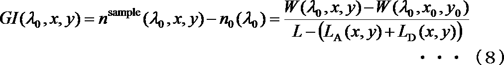
以上より、特定の波長における被検レンズ60の屈折率分布GI(λ0,x,y)が、数式8のように算出される。数式8の右辺の分母L−(LA(x,y)+LD(x,y))は、被検レンズ60の厚みの設計値とほぼ等しいため、L−(LA(x,y)+LD(x,y))の代わりに被検レンズ60の厚みの設計値で代用してもよい。
From the above, the refractive index distribution GI(λ 0 , x, y) of the
本実施例の計測方法は、被検レンズ60の形状誤差(形状の設計値からの乖離)及び被検レンズ60の屈折率誤差(屈折率の設計値からの乖離)によって発生する屈折率分布の算出誤差を、基準レンズの形状及び屈折率を用いて補正している。そのため、光学素子の屈折率分布を非破壊かつ高精度に計測できる。
The measuring method of the present embodiment is based on the refractive index distribution caused by the shape error of the
本実施例の計測方法は、被検レンズ60の屈折率とほぼ等しい屈折率を有する媒質(マッチング液)を用いずに、被検レンズ60の屈折率分布を計測する。したがって、実効的なマッチング液が得られない高屈折率(nd〜1.8以上)の光学素子の屈折率分布も、高精度に算出できる。
The measurement method of the present embodiment measures the refractive index distribution of the
本実施例では、図1のように、被検レンズ60に対して被検光が垂直に入射する構成で被検レンズ60の屈折率分布を計測したが、図5のように被検レンズ60に対して被検光が斜めに入射する構成でも被検レンズ60の屈折率分布を計測できる。斜入射配置による被検レンズ60の屈折率分布計測によって、被検レンズ60の光軸方向の屈折率分布が算出できる。光軸方向とは、被検レンズ60の第1面頂点から第2面頂点に向かう方向を指す。
In this embodiment, as shown in FIG. 1, the refractive index distribution of the
まず、被検光に対して被検ユニット200の傾きが異なる複数の配置において、被検ユニット200の透過波面が測定される。被検光に対する被検ユニット200の傾き角度は、回転ステージ140の回転量をコンピュータ90で制御することで調整される。
First, the transmitted wavefront of the unit to be measured 200 is measured in a plurality of arrangements in which the unit to be measured 200 has different inclinations with respect to the light to be measured. The tilt angle of the unit to be inspected 200 with respect to the light to be inspected is adjusted by controlling the rotation amount of the
そして、複数の配置において、被検レンズ60の屈折率分布が算出される。本実施例で算出される屈折率分布は、被検レンズ60の3次元屈折率分布を、被検光の透過方向に投影した屈折率分布投影値である。斜入射配置による被検レンズ60の屈折率分布投影値は、傾き角度に応じた被検レンズ60の光軸方向の屈折率分布情報を有する。複数の配置において屈折率分布投影値を算出すれば、被検レンズ60の光軸方向の屈折率分布情報を抽出できる。
Then, in a plurality of arrangements, the refractive index distribution of the
図5(a)、(b)は、被検光に対して被検ユニット200を傾けたときの光線の進み方を示している。被検ユニット200の傾き角が大きくなるに従い、被検ユニット200の表面における屈折角が大きくなる。屈折角が大きくなると、入射する被検光に対して透過する被検光のシフト量が大きくなる。また、この屈折の影響で、被検レンズ60に対する被検光の入射角度が、被検ユニット200の傾き角度に比べて小さいという問題がある。入射角度が小さいと、被検レンズ60の光軸方向の屈折率分布情報はあまり得られない。
5A and 5B show how a light beam travels when the
図5(c)、(d)は、上記問題を解決する方法を示している。被検ユニット200の傾き角度と同じ角度の頂角を有するプリズム150、151、155、156を被検ユニット200の前後に挿入することで、屈折の影響を低減している。
5C and 5D show a method for solving the above problem. The influence of refraction is reduced by inserting
プリズム150、151、155、156は、第1及び第2基準レンズと同一材質で製作されている。プリズム150、151、155、156と被検ユニット200のそれぞれの隙間には、隙間における屈折の影響を低減するために媒質71が塗布されている。
The
図5(c)、(d)のように、被検ユニット200の傾き角と同じ頂角を有するプリズムを用いることで、被検ユニット200の傾き角度と同じ入射角度の屈折率分布投影値が得られる。
As shown in FIGS. 5C and 5D, by using the prism having the same apex angle as the tilt angle of the unit under
光路長分布(=屈折率分布×L(x,y))は、モールドレンズの光学性能を示す物理量として、屈折率分布の代用が可能である。したがって、本発明の屈折率分布計測方法(屈折率分布計測装置)は、光路長分布計測方法(光路長分布計測装置)も意味する。 The optical path length distribution (=refractive index distribution×L(x,y)) can be substituted for the refractive index distribution as a physical quantity indicating the optical performance of the molded lens. Therefore, the refractive index distribution measuring method (refractive index distribution measuring apparatus) of the present invention also means an optical path length distribution measuring method (optical path length distribution measuring apparatus).
本実施例では、複数の波長の光を射出する光源とモノクロメータの組み合わせで波長を走査した。複数の波長の光を射出する光源としてスーパーコンティニューム光源が使用されているが、光周波数コム、スーパールミネッセントダイオード(SLD)、短パルスレーザ、ハロゲンランプが代用できる。 In this embodiment, the wavelength is scanned by a combination of a light source that emits light of a plurality of wavelengths and a monochromator. A supercontinuum light source is used as a light source that emits light of a plurality of wavelengths, but an optical frequency comb, a super luminescent diode (SLD), a short pulse laser, and a halogen lamp can be used instead.
複数の波長の光を射出する光源とモノクロメータの組み合わせの代わりに、波長掃引光源でもよいし、複数の波長を離散的に射出するマルチラインレーザでもよい。複数の波長の光を射出する光源は、単一の光源に限らず、複数の光源を組み合わせでもよい。本実施例は、2種類以上の波長の光を射出する光源であれば足りる。 Instead of a combination of a light source that emits light of a plurality of wavelengths and a monochromator, a wavelength swept light source may be used, or a multiline laser that discretely emits a plurality of wavelengths may be used. The light source that emits light of a plurality of wavelengths is not limited to a single light source, and a plurality of light sources may be combined. This embodiment is sufficient if it is a light source that emits light of two or more types of wavelengths.
本実施例では、干渉光学系にマッハツェンダ干渉計を用いた。その代わりにトワイマングリーン干渉計やフィゾー干渉計が代用できる。 In this embodiment, a Mach-Zehnder interferometer is used for the interference optical system. Instead, a Twyman Green interferometer or a Fizeau interferometer can be substituted.
本実施例では、第1基準レンズ120の第2面の面形状と被検レンズ60の第1面の面形状との差、及び被検レンズ60の第2面の面形状と第2基準レンズの第1面の面形状との差が、実施例1よりも大きい場合の屈折率分布計測方法を説明する。本実施例では、この面形状の差(形状成分)を、2種類の異なる波長における透過波面を用いて除去する。
In this embodiment, the difference between the surface shape of the second surface of the
図6は、本発明における実施例2の屈折率分布計測装置の概略構成を示す図である。本実施例では、実施例1で使用した干渉光学系を使用せずに、シャックハルトマンセンサ81を用いて透過波面を測定する。光源11はマルチラインガスレーザ(例えば、アルゴンレーザやクリプトンレーザ)、被検レンズ60は負の屈折力をもつレンズである。実施例1と同様の構成については、同一の符号を付して説明する。
FIG. 6 is a diagram showing a schematic configuration of a refractive index distribution measuring apparatus according to the second embodiment of the present invention. In this embodiment, the transmitted wavefront is measured using the Shack-
被検ユニット200は、容器50内に満たされた媒質70中に配置されている。本実施例における被検ユニット200は、図6のように、第1基準レンズ120、被検レンズ60、第2基準レンズ125、媒質70、補助ガラス127、128、129で構成されており、全体で直方体(または円柱)になっている。被検レンズ60の第1面及び第2面は非球面である。第1基準レンズ120の第2面は、被検レンズ60の第1面の非球面形状に近い球面であり、第2基準レンズ125の第1面は、被検レンズ60の第2面の非球面形状に近い球面である。
The unit to be tested 200 is arranged in the medium 70 filled in the
本実施例では、被検レンズ60の切断端(コバ)付近の屈折率nsample(λ,a,b)が既知としている。被検レンズ60の屈折率は、例えば、被検レンズ60のコバ付近をプリズム形状に加工して最小偏角法で計測できる。また、第1基準レンズ120、第2基準レンズ125、補助ガラス127、128、129はすべて同一材質で製作されており、すべての面形状及び屈折率n0(λ)が既知の量である。
In this embodiment, the refractive index n sample (λ, a, b) near the cut end (edge) of the
光源11から射出した光は、モノクロメータ20によって分光され、ピンホール30を透過して発散光となり、コリメータレンズ40によって平行光となる。平行光は、容器50内の媒質70中に配置された被検ユニット200を透過し、シャックハルトマンセンサ81で検出される。シャックハルトマン81で検出された信号は、コンピュータ90に送られる。容器50には、不図示の温度計が配置されている。媒質70の屈折率は、温度計により測定された媒質70の温度と、媒質70の屈折率の温度係数とを用いてコンピュータ90で算出される。
The light emitted from the
本実施例における被検レンズ60の屈折率分布の算出方法を以下に示す。本実施例は、まず、被検レンズ60を第1基準レンズ120と第2基準レンズ125と媒質70と補助ガラス127、128、129とで挟んで被検ユニット200を構成し、被検ユニット200を容器50内の光路上に配置する。
A method of calculating the refractive index distribution of the
そして、第1の波長λ1(例えば、λ1=457nm)における被検ユニット200の第1の透過波面W(λ1,x,y)と、第2の波長λ2(例えば、λ2=514nm)における被検ユニット200の第2の透過波面W(λ2,x,y)とを測定する。波長λにおける透過波面W(λ,x,y)は、数式9で表される。さらに、数式9は、数式2と、数式10の近似を用いて数式11のように変形できる。数式11は、座標(a,b)において、数式12のように表される。数式13は、数式11から数式12を減算して、定数項Cを消去した式である。数式中の記号の意味は、実施例1と同一である。
Then, the first transmitted wavefront W(λ 1 , x, y) of the unit under
第1基準レンズ120の形状及び屈折率と、第2基準レンズ125の形状及び屈折率と、第1の波長における被検ユニット200の透過波面と、第2の波長における被検ユニット200の透過波面とを用いて、第1及び第2基準レンズと被検レンズ60との面形状の差(形状成分)LB(x,y)−LB(0,0)+LC(x,y)−LC(0,0)を除去できる。
The shape and refractive index of the
第1波長における被検レンズ60の屈折率分布GI(λ1,x,y)は、数式14の近似を用いて数式15のように算出される。第2波長における被検レンズ60の屈折率分布GI(λ2,x,y)は、数式14、数式15を用いて数式16のように表される。
The refractive index distribution GI(λ 1 , x, y) of the
本実施例では、第1及び第2基準レンズと被検レンズとの面形状差が大きい場合に、異なる2種類の波長における透過波面を用いて面形状差(形状成分)を除去して屈折率分布を算出した。形状成分の除去には、2種類の波長の代わりに、屈折率の異なる2種類の媒質を利用してもよい。屈折率の異なる2種類の媒質を用いて被検ユニット200を構成し、被検ユニット200の透過波面を測定すれば、形状成分を除去して屈折率分布を算出できる。その方法は次のとおりである。
In this embodiment, when the surface shape difference between the first and second reference lenses and the test lens is large, the surface shape difference (shape component) is removed by using the transmitted wavefronts at two different wavelengths, and the refractive index. The distribution was calculated. In order to remove the shape component, two types of media having different refractive indexes may be used instead of the two types of wavelengths. If the
第1基準レンズ120と、第2基準レンズ125と、第1の屈折率n1 medium(λ)を有する第1の媒質と補助ガラス127、128、129とを用いて被検レンズ60を挟み、第1の被検ユニットを構成する。そして、第1の被検ユニットの第1の透過波面を測定する。第1の被検ユニットの第1の透過波面W1(λ,x,y)は、数式17のように表される。
The
第1基準レンズ120と、第2基準レンズ125と、第1の屈折率n1 medium(λ)と異なる第2の屈折率n2 medium(λ)を有する第2の媒質と補助ガラス127、128、129とを用いて被検レンズ60を挟み、第2の被検ユニットを構成する。そして、第2の被検ユニットの第2の透過波面を測定する。第2の被検ユニットの第2の透過波面W2(λ,x,y)は、数式18のように表される。
The
最後に、第1基準レンズ120の形状及び屈折率と、第2基準レンズ125の形状及び屈折率と、第1の透過波面と、第2の透過波面とを用いて、被検レンズ60の形状成分を除去して屈折率分布を算出する。定数項Cは、数式12、13と同様の方法で消去できる。被検レンズ60の屈折率分布GI(λ,x,y)は、数式19のように表される。
Finally, using the shape and refractive index of the
2種類の波長や2種類の媒質を用いる代わりに、第1、第2基準レンズを用いて特定の屈折率分布を有する基準被検レンズを挟んで構成された基準被検ユニットの透過波面を用いて、第1、第2基準レンズと被検レンズ60との面形状の差の影響を低減できる。
Instead of using two kinds of wavelengths and two kinds of media, a transmitted wavefront of a reference unit to be measured, which is constructed by sandwiching a reference sample lens having a specific refractive index distribution using the first and second reference lenses, is used. Thus, the influence of the difference in surface shape between the first and second reference lenses and the
本実施例では、基準被検レンズの屈折率分布として、屈折率nsample(λ,a,b)の一様な屈折率分布を仮定する。基準被検レンズの形状として被検レンズ60の設計値を用いる。第1基準レンズと第2基準レンズとを用いて基準被検レンズを挟むことにより構成される基準被検ユニットの透過波面Wsim(λ,x,y)は、数式20のように表される。ただし、C’は任意定数である。
In this embodiment, a uniform refractive index distribution of the refractive index n sample (λ,a,b) is assumed as the refractive index distribution of the reference test lens. The design value of the
δLB(x,y)は被検レンズ60の第1面形状と基準被検レンズの第1面形状との差、δLC(x,y)は被検レンズ60の第2面形状と基準被検レンズの第2面形状との差である。この基準被検ユニットの透過波面Wsim(λ,x,y)を用いると、第1及び第2基準レンズと被検レンズ60との面形状の差の影響(数式11の右辺第2項)を低減できる。
δL B (x, y) is the difference between the first surface shape of the lens under
被検ユニット200の透過波面W(λ,x,y)(数式11)と、基準被検ユニットの透過波面Wsim(λ,x,y)(数式20)との差は、数式21のように表される。 The difference between the transmitted wavefront W(λ,x,y) (Equation 11) of the unit to be measured 200 and the transmitted wavefront W sim (λ,x,y) (Equation 20) of the reference unit to be inspected is as shown in Equation 21. Represented by.
δLB(x,y)やδLC(x,y)は、被検レンズ60の製造誤差程度の小さな値なので、数式22の近似が成り立つ。数式21から数式12、13と同様の方法で定数項C−C’を消去して、数式22の近似を用いると、被検レンズ60の屈折率分布GI(λ,x,y)が、数式23のように表される。
Since δL B (x, y) and δL C (x, y) are values that are as small as the manufacturing error of the lens under
本実施例では、被検ユニット200の透過波面の測定にシャックハルトマンセンサ81を使用した。シャックハルトマンセンサの代わりにタルボ干渉計のようなシアリング干渉計を用いてもよい。
In this embodiment, the Shack-
本実施例では、モノクロメータ20を用いて波長を制御したが、モノクロメータの代わりに波長選択フィルタを用いてもよい。
In this embodiment, the wavelength is controlled using the
本実施例では、複数の波長を射出する光源(マルチラインガスレーザ)を用いたが、2種類の媒質を用いる方式や基準被検レンズを用いる方式を使用する場合は、単一波長の光源(例えば、HeNeレーザ)で良い。 In this embodiment, a light source (multi-line gas laser) that emits a plurality of wavelengths is used. However, when a method using two types of media or a method using a reference test lens is used, a light source with a single wavelength (for example, , HeNe laser).
実施例1、実施例2で説明した装置及び方法を用いて計測された屈折率分布の結果を、モールドレンズ等の光学素子の製造方法にフィードバックすることも可能である。 It is also possible to feed back the result of the refractive index distribution measured using the apparatus and method described in the first and second embodiments to the method for manufacturing an optical element such as a molded lens.
図7には、モールド成型を利用した光学素子の製造工程の例を示している。 FIG. 7 shows an example of a manufacturing process of an optical element using molding.
光学素子は、光学素子の設計工程、金型の設計工程及び、設計された金型を用いた光学素子のモールド工程を経て製造される。モールドされた光学素子は、その形状精度が評価され、精度不足である場合は金型を補正して再度モールドを行う。形状精度が良好であれば、光学素子の光学性能が評価される。この光学性能の評価工程に、本発明の屈折率分布計測方法を組み込むことで、高屈折率硝材を母材としてモールドされる光学素子の量産が可能になる。なお、光学性能が低い場合は、光学面を補正した光学素子を設計し直す。 The optical element is manufactured through an optical element designing step, a die designing step, and an optical element molding step using the designed die. The shape accuracy of the molded optical element is evaluated, and if the accuracy is insufficient, the mold is corrected and molding is performed again. If the shape accuracy is good, the optical performance of the optical element is evaluated. By incorporating the refractive index distribution measuring method of the present invention in this optical performance evaluation step, it becomes possible to mass-produce optical elements molded using a high refractive index glass material as a base material. If the optical performance is low, redesign the optical element with the corrected optical surface.
以上、説明した各実施例は代表的な例に過ぎず、本発明の実施に際しては、各実施例に対して種々の変形や変更が可能である。 The embodiments described above are merely representative examples, and various modifications and changes can be made to the embodiments when implementing the present invention.
10 光源
60 被検レンズ
71 媒質
80 検出器
90 コンピュータ
120 第1基準レンズ
125 第2基準レンズ
200 被検ユニット
10
Claims (13)
前記第1基準レンズの形状及び屈折率と、前記第2基準レンズの形状及び屈折率と、前記被検ユニットの透過波面とを用いて、前記被検ユニットの透過波面の不確定な定数成分に由来する屈折率分布誤差を補正して、前記被検レンズの屈折率分布を算出する算出ステップと、
を含むことを特徴とする屈折率分布計測方法。 A transmitted wavefront of a unit to be measured, which is configured by sandwiching the lens to be measured with a first reference lens having a known shape and a refractive index, a second reference lens having a known shape and a refractive index, and a medium, is measured Measurement step,
Using the shape and refractive index of the first reference lens, the shape and refractive index of the second reference lens, and the transmitted wavefront of the unit under test, an uncertain constant component of the transmitted wavefront of the unit under test is obtained. Compensating the refractive index distribution error resulting from, a calculation step of calculating the refractive index distribution of the lens under test,
A method of measuring a refractive index distribution, comprising:
前記複数の波長における前記被検ユニットの透過波面から前記特定の波長を決定し、
前記特定の波長における透過波面を用いて、前記被検レンズの屈折率分布を算出することを特徴とする請求項2に記載の屈折率分布計測方法。 Measuring the transmitted wavefront of the unit under test at a plurality of wavelengths,
Determining the specific wavelength from the transmitted wavefront of the unit under test at the plurality of wavelengths,
The refractive index distribution measuring method according to claim 2, wherein the refractive index distribution of the lens to be tested is calculated using a transmitted wavefront at the specific wavelength.
前記複数の配置における前記被検ユニットの透過波面を用いて、前記被検レンズの光軸方向の屈折率分布を算出することを特徴とする請求項1から3のいずれか1項に記載の屈折率分布計測方法。 Measuring the transmitted wavefront of the unit to be inspected for a plurality of arrangements in which the inclination of the unit to be inspected with respect to the light to be inspected is different,
The refraction according to any one of claims 1 to 3, wherein the refractive index distribution in the optical axis direction of the lens under test is calculated by using the transmitted wavefronts of the unit under test in the plurality of arrangements. Rate distribution measurement method.
前記第1基準レンズの形状及び屈折率と、前記第2基準レンズの形状及び屈折率と、前記第1の波長における前記被検ユニットの透過波面と、前記第2の波長における前記被検ユニットの透過波面とを用いて、前記被検レンズの形状成分を除去して、前記被検レンズの屈折率分布を算出することを特徴とする請求項1から4のいずれか1項に記載の屈折率分布計測方法。 Measuring a transmitted wavefront of the unit under test at a first wavelength and a transmitted wavefront of the unit under test at a second wavelength different from the first wavelength;
The shape and the refractive index of the first reference lens, the shape and the refractive index of the second reference lens, the transmitted wavefront of the unit under test at the first wavelength, and the unit of the unit under test at the second wavelength. The refractive index distribution according to any one of claims 1 to 4, wherein a shape component of the lens under test is removed by using a transmitted wavefront to calculate a refractive index distribution of the lens under test. Distribution measurement method.
前記第1基準レンズと、前記第2基準レンズと、前記第1の屈折率と異なる第2の屈折率を有する第2の媒質とを用いて前記被検レンズを挟むことにより構成される第2の被検ユニットの透過波面を測定し、
前記第1基準レンズの形状及び屈折率と、前記第2基準レンズの形状及び屈折率と、前記第1の被検ユニットの透過波面と、前記第2の被検ユニットの透過波面とを用いて、前記被検レンズの形状成分を除去して、前記被検レンズの屈折率分布を算出することを特徴とする請求項1から4のいずれか1項に記載の屈折率分布計測方法。 A transmitted wavefront of a first unit to be tested formed by sandwiching the lens to be tested by using the first reference lens, the second reference lens, and a first medium having a first refractive index. Measure
A second configuration formed by sandwiching the lens under test using the first reference lens, the second reference lens, and a second medium having a second refractive index different from the first refractive index. Measure the transmitted wavefront of the unit to be tested,
Using the shape and refractive index of the first reference lens, the shape and refractive index of the second reference lens, the transmitted wavefront of the first unit under test, and the transmitted wavefront of the second unit under test The refractive index distribution measuring method according to any one of claims 1 to 4, wherein the shape component of the test lens is removed to calculate the refractive index distribution of the test lens.
請求項1から7のいずれか1項に記載の屈折率分布計測方法を用いて前記光学素子の屈折率分布を計測することによって、モールドされた光学素子の光学性能を評価するステップと、を含むことを特徴とする光学素子の製造方法。 Molding the optical element,
Evaluating the optical performance of the molded optical element by measuring the refractive index distribution of the optical element using the refractive index distribution measuring method according to any one of claims 1 to 7. A method for manufacturing an optical element, comprising:
前記第1基準レンズの形状及び屈折率と、前記第2基準レンズの形状及び屈折率と、前記被検ユニットの透過波面とを用いて、前記被検ユニットの透過波面の不確定な定数成分に由来する屈折率分布誤差を補正して、前記被検レンズの屈折率分布を算出する算出手段と、
を有することを特徴とする屈折率分布計測装置。 Measurement for measuring a transmitted wavefront of a unit to be tested, which is formed by sandwiching a lens to be tested with a first reference lens having a known shape and refractive index, a second reference lens having a known shape and refractive index, and a medium. Means and
Using the shape and refractive index of the first reference lens, the shape and refractive index of the second reference lens, and the transmitted wavefront of the unit under test, an uncertain constant component of the transmitted wavefront of the unit under test is obtained. Correcting the refractive index distribution error derived from, a calculating means for calculating the refractive index distribution of the lens under test,
A refractive index distribution measuring device comprising:
Priority Applications (3)
| Application Number | Priority Date | Filing Date | Title |
|---|---|---|---|
| US14/959,878 US9709490B2 (en) | 2014-12-08 | 2015-12-04 | Refractive index distribution measuring method, refractive index distribution measuring apparatus, and optical element manufacturing method |
| KR1020150171931A KR20160069476A (en) | 2014-12-08 | 2015-12-04 | Refractive index distribution measuring method, refractive index distribution measuring apparatus, and optical element manufacturing method |
| CN201510893831.0A CN105675261A (en) | 2014-12-08 | 2015-12-08 | Refractive index distribution measuring method, refractive index distribution measuring apparatus, and optical element manufacturing method |
Applications Claiming Priority (2)
| Application Number | Priority Date | Filing Date | Title |
|---|---|---|---|
| JP2014248475 | 2014-12-08 | ||
| JP2014248475 | 2014-12-08 |
Publications (2)
| Publication Number | Publication Date |
|---|---|
| JP2016109670A JP2016109670A (en) | 2016-06-20 |
| JP6700699B2 true JP6700699B2 (en) | 2020-05-27 |
Family
ID=56123747
Family Applications (1)
| Application Number | Title | Priority Date | Filing Date |
|---|---|---|---|
| JP2015190070A Active JP6700699B2 (en) | 2014-12-08 | 2015-09-28 | Refractive index distribution measuring method, refractive index distribution measuring apparatus, and optical element manufacturing method |
Country Status (3)
| Country | Link |
|---|---|
| JP (1) | JP6700699B2 (en) |
| KR (1) | KR20160069476A (en) |
| CN (1) | CN105675261A (en) |
Families Citing this family (4)
| Publication number | Priority date | Publication date | Assignee | Title |
|---|---|---|---|---|
| CN109444077B (en) * | 2018-11-30 | 2020-04-07 | 中山大学 | Quantitative measurement system and method for refractive index field based on phase calibration |
| CN109855541B (en) * | 2019-01-21 | 2020-08-04 | 山西大学 | Air refractive index self-calibration system and method based on optical frequency comb |
| JP7794829B2 (en) * | 2021-07-20 | 2026-01-06 | 株式会社日立ハイテク | Far-infrared spectrometer and sample adapter |
| KR102781336B1 (en) * | 2022-12-08 | 2025-03-18 | 한국표준과학연구원 | A complex wavefront inspection system combining a Fizeau interferometer and a Shack-Hartmann sensor |
Family Cites Families (15)
| Publication number | Priority date | Publication date | Assignee | Title |
|---|---|---|---|---|
| US5151752A (en) * | 1988-06-16 | 1992-09-29 | Asahi Kogaku Kogyo K.K. | Method of measuring refractive indices of lens and sample liquid |
| JP3699810B2 (en) * | 1997-07-29 | 2005-09-28 | 株式会社リコー | Method and apparatus for measuring refractive index distribution |
| JP2002188979A (en) * | 2000-12-22 | 2002-07-05 | Nikon Corp | Method of measuring refractive index distribution, measuring device of refractive index distribution, method of manufacturing optical system, and optical system |
| JP4929529B2 (en) * | 2001-03-27 | 2012-05-09 | 株式会社ニコン | OPTICAL SYSTEM MANUFACTURING METHOD AND EXPOSURE APPARATUS PROVIDED WITH OPTICAL SYSTEM PRODUCED BY THE MANUFACTURING METHOD |
| JP4319554B2 (en) * | 2004-01-14 | 2009-08-26 | 株式会社リコー | Refractive index distribution measuring method and measuring apparatus |
| CN101464209A (en) * | 2007-12-19 | 2009-06-24 | 鸿富锦精密工业(深圳)有限公司 | Method and apparatus for measuring refractive index variable quantity of lens |
| JP5008650B2 (en) * | 2008-12-25 | 2012-08-22 | キヤノン株式会社 | Refractive index distribution measuring method and refractive index distribution measuring apparatus |
| US8269981B1 (en) * | 2009-03-30 | 2012-09-18 | Carl Zeiss Smt Gmbh | Method and an apparatus for measuring a deviation of an optical test surface from a target shape |
| JP2011080875A (en) * | 2009-10-07 | 2011-04-21 | Tokyo Institute Of Technology | Apparatus and method for measuring refraction index distribution |
| JP4895409B2 (en) * | 2010-05-25 | 2012-03-14 | キヤノン株式会社 | Refractive index distribution measuring method and refractive index distribution measuring apparatus |
| JP5868142B2 (en) * | 2011-11-24 | 2016-02-24 | キヤノン株式会社 | Refractive index distribution measuring method and refractive index distribution measuring apparatus |
| JP5575161B2 (en) * | 2012-02-10 | 2014-08-20 | キヤノン株式会社 | Refractive index distribution measuring method and refractive index distribution measuring apparatus |
| JP2014016253A (en) * | 2012-07-09 | 2014-01-30 | Canon Inc | Refractive index distribution measurement method, method of manufacturing optical element, and refractive index distribution measurement instrument |
| JP2014196966A (en) * | 2013-03-29 | 2014-10-16 | コニカミノルタ株式会社 | Refractive index distribution-measuring reference element, and device and method for measuring refractive index distribution |
| JP2015099133A (en) * | 2013-11-20 | 2015-05-28 | キヤノン株式会社 | Measurement method and measurement device for thickness |
-
2015
- 2015-09-28 JP JP2015190070A patent/JP6700699B2/en active Active
- 2015-12-04 KR KR1020150171931A patent/KR20160069476A/en not_active Ceased
- 2015-12-08 CN CN201510893831.0A patent/CN105675261A/en active Pending
Also Published As
| Publication number | Publication date |
|---|---|
| CN105675261A (en) | 2016-06-15 |
| KR20160069476A (en) | 2016-06-16 |
| JP2016109670A (en) | 2016-06-20 |
Similar Documents
| Publication | Publication Date | Title |
|---|---|---|
| US9709490B2 (en) | Refractive index distribution measuring method, refractive index distribution measuring apparatus, and optical element manufacturing method | |
| JP6157240B2 (en) | Refractive index measuring method, refractive index measuring apparatus, and optical element manufacturing method | |
| US8520218B2 (en) | Measuring method of refractive index and measuring apparatus of refractive index | |
| JP4895409B2 (en) | Refractive index distribution measuring method and refractive index distribution measuring apparatus | |
| US10330461B2 (en) | Calibration of an interferometer | |
| JP6700699B2 (en) | Refractive index distribution measuring method, refractive index distribution measuring apparatus, and optical element manufacturing method | |
| KR20160145496A (en) | Refractive index measurement method, measurement apparatus, and optical element manufacturing method | |
| JP5868142B2 (en) | Refractive index distribution measuring method and refractive index distribution measuring apparatus | |
| TWI570397B (en) | Optical evaluation of lenses and lens molds | |
| JP2017198613A (en) | Refractive index measurement method, refractive index measurement device, and optical element manufacturing method | |
| JP2015099133A (en) | Measurement method and measurement device for thickness | |
| KR20160142235A (en) | Measurement method, measurement apparatus, and manufacturing method for optical element | |
| US9625350B2 (en) | Refractive index distribution measuring method, refractive index distribution measuring apparatus, and method for manufacturing optical element | |
| JP2015105850A (en) | Refractive index measuring method, refractive index measuring apparatus, and optical element manufacturing method | |
| JP6157241B2 (en) | Refractive index measuring method, refractive index measuring apparatus, and optical element manufacturing method | |
| JP5500354B2 (en) | Membrane structure measuring method and surface shape measuring apparatus | |
| Lassila et al. | Wave front and phase correction for double-ended gauge block interferometry | |
| TWI596325B (en) | Method or system for dertermining information about an object or a transparent optical element and method of forming an optical assembly | |
| JP2015010920A (en) | Refractive index measuring method, refractive index measuring apparatus, and optical element manufacturing method | |
| JP2015210241A (en) | Wavefront measuring method, wavefront measuring apparatus, and optical element manufacturing method | |
| JP2016109595A (en) | Refractive index distribution measurement method, refractive index distribution measurement device, and optical element manufacturing method | |
| JP6407000B2 (en) | Refractive index measuring method, refractive index measuring apparatus, and optical element manufacturing method | |
| JP2016109592A (en) | Refractive index distribution measurement method, refractive index distribution measurement device, and optical element manufacturing method | |
| JP2000180134A (en) | Measuring method | |
| KR20160071298A (en) | Curvature of both sides surface and refractive index profile simultaneous measurement method of the lens |
Legal Events
| Date | Code | Title | Description |
|---|---|---|---|
| A621 | Written request for application examination |
Free format text: JAPANESE INTERMEDIATE CODE: A621 Effective date: 20180921 |
|
| A977 | Report on retrieval |
Free format text: JAPANESE INTERMEDIATE CODE: A971007 Effective date: 20190724 |
|
| A131 | Notification of reasons for refusal |
Free format text: JAPANESE INTERMEDIATE CODE: A131 Effective date: 20190820 |
|
| A521 | Written amendment |
Free format text: JAPANESE INTERMEDIATE CODE: A523 Effective date: 20191018 |
|
| TRDD | Decision of grant or rejection written | ||
| A01 | Written decision to grant a patent or to grant a registration (utility model) |
Free format text: JAPANESE INTERMEDIATE CODE: A01 Effective date: 20200331 |
|
| A61 | First payment of annual fees (during grant procedure) |
Free format text: JAPANESE INTERMEDIATE CODE: A61 Effective date: 20200501 |
|
| R151 | Written notification of patent or utility model registration |
Ref document number: 6700699 Country of ref document: JP Free format text: JAPANESE INTERMEDIATE CODE: R151 |