JP6696565B2 - Fluid spray system - Google Patents
Fluid spray system Download PDFInfo
- Publication number
- JP6696565B2 JP6696565B2 JP2018505924A JP2018505924A JP6696565B2 JP 6696565 B2 JP6696565 B2 JP 6696565B2 JP 2018505924 A JP2018505924 A JP 2018505924A JP 2018505924 A JP2018505924 A JP 2018505924A JP 6696565 B2 JP6696565 B2 JP 6696565B2
- Authority
- JP
- Japan
- Prior art keywords
- water
- tank
- compressed air
- pure water
- fluid
- Prior art date
- Legal status (The legal status is an assumption and is not a legal conclusion. Google has not performed a legal analysis and makes no representation as to the accuracy of the status listed.)
- Active
Links
- 239000012530 fluid Substances 0.000 title claims description 68
- 239000007921 spray Substances 0.000 title claims description 50
- XLYOFNOQVPJJNP-UHFFFAOYSA-N water Substances O XLYOFNOQVPJJNP-UHFFFAOYSA-N 0.000 claims description 146
- 238000005507 spraying Methods 0.000 claims description 8
- 239000007788 liquid Substances 0.000 claims description 7
- CURLTUGMZLYLDI-UHFFFAOYSA-N Carbon dioxide Chemical compound O=C=O CURLTUGMZLYLDI-UHFFFAOYSA-N 0.000 description 57
- 239000000463 material Substances 0.000 description 40
- 229910002092 carbon dioxide Inorganic materials 0.000 description 28
- 239000001569 carbon dioxide Substances 0.000 description 28
- 238000010586 diagram Methods 0.000 description 16
- 239000002245 particle Substances 0.000 description 15
- 230000000694 effects Effects 0.000 description 6
- -1 polypropylene Polymers 0.000 description 5
- 238000001223 reverse osmosis Methods 0.000 description 5
- 239000004743 Polypropylene Substances 0.000 description 4
- 239000002184 metal Substances 0.000 description 4
- 238000000034 method Methods 0.000 description 4
- 229920001155 polypropylene Polymers 0.000 description 4
- 239000000470 constituent Substances 0.000 description 3
- 239000008367 deionised water Substances 0.000 description 3
- 229910021641 deionized water Inorganic materials 0.000 description 3
- 238000000889 atomisation Methods 0.000 description 2
- 239000012535 impurity Substances 0.000 description 2
- 238000002347 injection Methods 0.000 description 2
- 239000007924 injection Substances 0.000 description 2
- 239000012528 membrane Substances 0.000 description 2
- 239000008399 tap water Substances 0.000 description 2
- 235000020679 tap water Nutrition 0.000 description 2
- 238000009736 wetting Methods 0.000 description 2
- NWUYHJFMYQTDRP-UHFFFAOYSA-N 1,2-bis(ethenyl)benzene;1-ethenyl-2-ethylbenzene;styrene Chemical compound C=CC1=CC=CC=C1.CCC1=CC=CC=C1C=C.C=CC1=CC=CC=C1C=C NWUYHJFMYQTDRP-UHFFFAOYSA-N 0.000 description 1
- 239000004698 Polyethylene Substances 0.000 description 1
- BZHJMEDXRYGGRV-UHFFFAOYSA-N Vinyl chloride Chemical compound ClC=C BZHJMEDXRYGGRV-UHFFFAOYSA-N 0.000 description 1
- 239000000919 ceramic Substances 0.000 description 1
- 238000001816 cooling Methods 0.000 description 1
- 238000004090 dissolution Methods 0.000 description 1
- 230000005611 electricity Effects 0.000 description 1
- 239000010419 fine particle Substances 0.000 description 1
- 239000007789 gas Substances 0.000 description 1
- JEGUKCSWCFPDGT-UHFFFAOYSA-N h2o hydrate Chemical compound O.O JEGUKCSWCFPDGT-UHFFFAOYSA-N 0.000 description 1
- 238000010438 heat treatment Methods 0.000 description 1
- 239000012510 hollow fiber Substances 0.000 description 1
- 238000009413 insulation Methods 0.000 description 1
- 239000003456 ion exchange resin Substances 0.000 description 1
- 229920003303 ion-exchange polymer Polymers 0.000 description 1
- 238000005259 measurement Methods 0.000 description 1
- 238000002844 melting Methods 0.000 description 1
- 230000008018 melting Effects 0.000 description 1
- 238000002156 mixing Methods 0.000 description 1
- 210000002445 nipple Anatomy 0.000 description 1
- 229920000573 polyethylene Polymers 0.000 description 1
- 230000003068 static effect Effects 0.000 description 1
- 238000004078 waterproofing Methods 0.000 description 1
Images


Classifications
-
- F—MECHANICAL ENGINEERING; LIGHTING; HEATING; WEAPONS; BLASTING
- F24—HEATING; RANGES; VENTILATING
- F24F—AIR-CONDITIONING; AIR-HUMIDIFICATION; VENTILATION; USE OF AIR CURRENTS FOR SCREENING
- F24F6/00—Air-humidification, e.g. cooling by humidification
- F24F6/12—Air-humidification, e.g. cooling by humidification by forming water dispersions in the air
- F24F6/14—Air-humidification, e.g. cooling by humidification by forming water dispersions in the air using nozzles
Description
本発明の実施形態は、流体を噴霧する流体噴霧システムに関する。 Embodiments of the present invention relate to a fluid spray system for spraying a fluid.
従来、噴霧ノズルにより純水を粒子にして室内空間に供給することにより、室内空間を加湿する加湿システムがある。 2. Description of the Related Art Conventionally, there is a humidification system that humidifies an indoor space by supplying pure water into the indoor space as particles by a spray nozzle.
加湿システムでは、噴霧した純水粒子が帯電し、噴霧ノズル本体、噴霧ノズル周囲にある壁、柱、配管、機器、付近を通る人、又は、製品に、クーロン力で引き寄せられて付着することがある。 In a humidification system, sprayed pure water particles are electrically charged and may be attracted by the Coulomb force and adhere to the spray nozzle body, walls around the spray nozzle, columns, pipes, equipment, people passing by, or products. is there.
これにより、水濡れ又は静電気による機器の故障、感電、若しくは、空中放電の問題を引き起こす為、狭くて障害物が多い場所、電子機器の有る場所、人が通る場所、濡れの許されない場所、又は、防爆仕様の要求される場所で、純水を噴霧することが困難である。 This may cause equipment failure due to water wetting or static electricity, electric shock, or air discharge problems. It is difficult to spray pure water in places where explosion-proof specifications are required.
本発明の目的は、噴霧することにより、少なくとも特定の箇所を濡らさないようにする流体噴霧システムを提供することにある。 It is an object of the present invention to provide a fluid spray system that sprays so that it does not wet at least certain locations.
本発明の観点に従った流体噴霧システムは、
第一の圧縮空気を供給する圧縮空気供給源と、
純水と比抵抗が1[MΩ・cm]を超える水とから成る群から選択した一つの水を供給する水供給源と、
前記圧縮空気供給源から供給される前記第一の圧縮空気をレギュレータで圧力制御することで第二の圧縮空気を生成し、前記第二の圧縮空気を前記水供給源から供給される前記水に溶解させることで前記水の導電率を調整する導電率調整手段と、
前記導電率調整手段により調整された前記水と前記圧縮空気供給源から供給された前記第一の圧縮空気を混合させて、霧化した流体を噴霧することで加湿を行う加湿用二流体ノズルと
を備え、
前記水供給源から供給される前記水を蓄える第一タンクを備え、
前記導電率調整手段は、前記第二の圧縮空気を前記第一タンクの下側から入れることで、前記第二の圧縮空気を前記第一タンクの中の前記水に溶解させ、
前記水供給源から供給される前記水を蓄える第二タンクを備え、
前記導電率調整手段は、前記第一の圧縮空気を前記第二タンクの下側から入れることで前記第一の圧縮空気を前記第二タンクの中の前記水に溶解させ、
前記第一タンクは、前記第二タンクを介して前記第一の圧縮空気が溶解された前記水を取得するように構築されたものである。
A fluid atomization system according to an aspect of the present invention comprises:
A compressed air supply source for supplying a first compressed air;
A water supply source for supplying one water selected from the group consisting of pure water and water having a specific resistance of more than 1 [M Ω · cm 2 ],
The second compressed air is generated by controlling the pressure of the first compressed air supplied from the compressed air supply source with a regulator, and the second compressed air is supplied to the water supplied from the water supply source. Conductivity adjusting means for adjusting the conductivity of the water by dissolving,
A two-fluid nozzle for humidification, which mixes the water adjusted by the conductivity adjusting unit with the first compressed air supplied from the compressed air supply source to perform humidification by spraying atomized fluid. Equipped with
A first tank for storing the water supplied from the water supply source;
The conductivity adjusting means, by inserting the second compressed air from the lower side of the first tank, to dissolve the second compressed air in the water in the first tank,
A second tank for storing the water supplied from the water supply source,
The conductivity adjusting means dissolves the first compressed air in the water in the second tank by introducing the first compressed air from the lower side of the second tank,
It said first tank, Ru der those constructed to obtain the water in which the first compressed air is dissolved through the second tank.
(第1の実施形態)
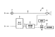
図1は、本発明の第1の実施形態に係る流体噴霧システム10の構成を示す構成図である。なお、図面における同一部分には同一符号を付してその詳しい説明を省略し、異なる部分について主に述べる。(First embodiment)
FIG. 1 is a configuration diagram showing a configuration of a
初めに、流体噴霧システム10により噴霧する流体について説明する。
First, the fluid sprayed by the
例えば、流体は、純水である。純水は、主に水道水を精製することにより得られる。例えば、純水は、次のように作る。 For example, the fluid is pure water. Pure water is mainly obtained by purifying tap water. For example, pure water is made as follows.
まず、逆浸透膜(RO(reverse osmosis)膜)を用いて、水道水から不純物を取り除くことで、RO水を作る。このRO水から、イオン交換樹脂を用いて、イオン成分及び残存する微細な不純物を取り除くことで、脱イオン水を作る。この脱イオン水が純水となる。一般に、水は、純度が高いほど比抵抗が高くなる。水の比抵抗が高くなると、水を粒子にした場合に、粒子が帯電し易くなる。具体的には、水の比抵抗が約1[MΩ・cm]を超えると、帯電するようになる。上述のように作られた純水の比抵抗は、1[MΩ・cm]を超えるため、噴霧すると帯電する。 First, RO water is produced by removing impurities from tap water using a reverse osmosis (RO) membrane. Deionized water is prepared by removing ion components and remaining fine impurities from the RO water using an ion exchange resin. This deionized water becomes pure water. Generally, the higher the purity of water, the higher the specific resistance. When the specific resistance of water is high, when water is used as particles, the particles are easily charged. Specifically, when the specific resistance of water exceeds about 1 [MΩ · cm], it becomes charged. Since the specific resistance of pure water produced as described above exceeds 1 [MΩ · cm], it is charged when sprayed.
なお、流体噴霧システム10で用いる純水2は、純度を高くするために精製された水であれば、上述の方法以外で精製されたものでもよい。例えば、純水2は、RO水、又は、RO水を介さない脱イオン水でもよい。
The
流体噴霧システム10は、加湿をするのであれば、冷却又は加熱などの温度調節を同時に行ってもよい。流体噴霧システム10は、二流体ノズル1、ポンプユニット3、材料溶解ユニット4、レギュレータ7、材料供給弁14、調節計15、及び、材料供給源17を備える。圧縮空気6は、レギュレータ7を介して、二流体ノズル1に供給される。
The
圧縮空気6が流れる空気供給路8は、圧縮空気6の供給源からレギュレータ7を介して二流体ノズル1に設けられた空気供給口に供給されるように設けられる。純水2が流れる水供給路5は、純水2の供給源からポンプユニット3及び材料溶解ユニット4を順次に介して、二流体ノズル1に設けられた水供給口に供給されるように設けられる。
The
二流体ノズル1は、液体と気体を混合させて、霧化された流体を噴霧するノズルである。本実施形態では、液体は純水2であり、気体は圧縮空気6である。
The two-
ポンプユニット3は、純水2の供給源から材料溶解ユニット4を介して、二流体ノズル1に純水2を送り込むための機器である。
The pump unit 3 is a device for feeding the
レギュレータ7は、圧縮空気6を二流体ノズル1に送り込むための機器である。
The regulator 7 is a device for sending the
材料供給源17は、導電率調整材料を蓄えるユニットである。導電率調整材料は、純水2の導電率を高くするために、純水2に溶解させるための材料である。導電率調整材料は、二流体ノズル1から噴霧された空間の環境になるべく影響を与えないものが望ましい。但し、噴霧される空間が許容するのであれば、導電率調整材料は、どのようなものでもよい。例えば、炭酸ガスは、空気中に含まれる成分であるため、噴霧しても環境への影響はほぼ無い。以降では、導電率調整材料は、主に炭酸ガスとして説明する。
The
調節計15は、材料供給弁14の開度を調節するための指示値を材料供給弁14に出力する。調節計15には、純水2の導電率が目標とする値(目標導電率)になるように、指示値が設定される。
The controller 15 outputs an instruction value for adjusting the opening degree of the material supply valve 14 to the material supply valve 14. An instruction value is set in the controller 15 so that the conductivity of the
材料供給弁14は、材料供給源17から材料溶解ユニット4に供給する炭酸ガスの量を調節するための弁である。材料供給弁14は、調節計15から受信した指示値により、開度を決定する。材料供給弁14の開度が大きいほど、材料溶解ユニット4に供給される炭酸ガスの量は多くなる。材料供給弁14から供給する炭酸ガスの量が多くなるほど、純水2の導電率は高くなる。
The material supply valve 14 is a valve for adjusting the amount of carbon dioxide gas supplied from the
材料溶解ユニット4は、材料供給源17から供給される炭酸ガスを純水2に溶解させるユニットである。材料溶解ユニット4の内部には、例えば中空糸膜又はセラミックが収納されている。材料溶解ユニット4は、純水2に炭酸ガスを混入する。炭酸ガスが純水2に溶解することで、純水2が目標導電率になる。例えば、目標導電率として、純水2の比抵抗を1.0MΩ・cm以下にする。材料溶解ユニット4は、炭酸ガスを純水2に溶解させ、目標導電率に達した純水2を二流体ノズル1に供給する。
The material dissolving unit 4 is a unit for dissolving the carbon dioxide gas supplied from the
二流体ノズル1は、材料溶解ユニット4から供給される炭酸ガスが溶解した純水2とレギュレータ7から供給される圧縮空気6を混合して噴霧する。これにより、二流体ノズル1は、純水2を微細な粒子にして噴霧する。
The two-
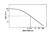
図2を参照して、純水2の導電率と炭酸ガスの溶解量との関係について説明する。図2において、縦軸は比抵抗(導電率)を示し、横軸は炭酸ガスの溶解量を示す。
The relationship between the conductivity of
純度が100%で、炭酸が溶解していない純水2の比抵抗は、約18.2MΩ・cmである。純水2の目標導電率(比抵抗)を1.0MΩ・cmとした場合、1Lの純水に0.6mg以上の炭酸ガスを溶解させることで目標導電率まで下がる。
The specific resistance of
図3を参照して、空気中の炭酸ガスを純水2に溶解させる場合について説明する。この場合、材料供給源17には、空気が蓄えられる。
A case where carbon dioxide gas in the air is dissolved in
重量が1293mg/Lで、炭酸ガス濃度が400ppmの空気の場合、この空気には、0.517mg/Lの炭酸ガスが含まれる。このように、炭酸ガスの濃度が分かれば、必要な炭酸ガスを含む空気重量が求まる。 In the case of air having a weight of 1293 mg / L and a carbon dioxide gas concentration of 400 ppm, the air contains 0.517 mg / L of carbon dioxide gas. Thus, if the concentration of carbon dioxide is known, the weight of air containing the required carbon dioxide can be obtained.
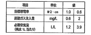
図4を参照して、調節計15の設定方法について説明する。 A method of setting the controller 15 will be described with reference to FIG.
調節計15を設定するには、純水2の目標導電率に対して、純水2に溶解させる炭酸ガス注入量又は必要な空気量を求める。例えば、図4では、目標導電率(比抵抗)が1.0MΩ・cmの場合、1Lの純水2に対する炭酸ガス注入量は0.6mgであり、1Lの純水2に対する必要な空気量は1.2Lである。目標導電率(比抵抗)が0.6MΩ・cmの場合、1Lの純水2に対する炭酸ガス注入量は2mgであり、1Lの純水2に対する必要な空気量は3.9Lである。
To set the controller 15, the amount of carbon dioxide gas to be dissolved in the
このように求めた炭酸ガス注入量又は必要な空気量に基づいて、材料供給弁14の開度を決定するための指示値を求める。このように求めた指示値が調節計15に設定される。 An instruction value for determining the opening degree of the material supply valve 14 is obtained based on the carbon dioxide injection amount or the required air amount thus obtained. The instruction value thus obtained is set in the controller 15.
本実施形態によれば、純水2に導電率調整材料を溶解させることで、噴霧された純水2を帯電させないようにすることができる。これにより、流体噴霧システム10により噴霧された純水2の粒子で、あらゆる物を濡らさないようにすることができる。例えば、噴霧ノズル本体、噴霧ノズル周囲にある壁、柱、配管、機器、付近を通る人、又は、製品などを、流体噴霧システム10による噴霧で濡らすことがない。したがって、これらの物を防滴加工又は防水加工する必要はない。
According to this embodiment, the sprayed
(第2の実施形態)
図5は、本発明の第2の実施形態に係る流体噴霧システム10Aの構成を示す構成図である。(Second embodiment)
FIG. 5: is a block diagram which shows the structure of 10 A of fluid spray systems which concern on the 2nd Embodiment of this invention.
流体噴霧システム10Aは、図1に示す第1の実施形態に係る流体噴霧システム10において、調節計15を調節計15Aに代え、導電率計16を追加したものである。
The
導電率計16は、二流体ノズル1と材料溶解ユニット4とを接続する水供給路5に設けられる。導電率計16は、水供給路5に流れる純水2の導電率を測定する。導電率計16は、測定した導電率を調節計15Aに送信する。
The
調節計15Aは、導電率計16による測定結果に基づいて、材料供給弁14の開度を決定する指示値を決定する。調節計15Aは、設定された指示値を修正してもよいし、新たに指示値を計算してもよい。調節計15Aは、決定した指示値を材料供給弁14に出力する。
The
本実施形態によれば、第1の実施形態による作用効果に加え、以下の作用効果を得ることができる。導電率計16を設けて、純水2の導電率を測定することで、純水2の導電率を制御することができる。これにより、純水2の導電率が低く過ぎることを防止することができる。また、純水2の導電率が高い場合、材料供給弁14の開度を低くして、炭酸ガスの供給を抑えることで、炭酸ガスの余剰な供給を防止することができる。
According to this embodiment, the following operational effects can be obtained in addition to the operational effects of the first embodiment. The conductivity of the
(第3の実施形態)
図6は、本発明の第3の実施形態に係る流体噴霧システム10Bの噴霧中の構成を示す構成図である。ここでは、第1の実施形態と異なる部分について主に説明する。(Third Embodiment)
FIG. 6 is a configuration diagram showing a configuration during spraying of the
流体噴霧システム10Bは、二流体ノズル1、圧力タンク31、供給タンク32、水供給弁33、6つの逆止弁34,35,36,37,38,39、水用電空レギュレータ40、空気用電空レギュレータ41、及び、三方弁42を備える。これらの機器は、水供給路5又は空気供給路8などの配管で接続されている。
The
空気用電空レギュレータ41は、圧縮空気6の供給源と二流体ノズル1との間の空気供給路8に設けられている。空気用電空レギュレータ41は、二流体ノズル1に供給される圧縮空気6の圧力を所望の値にする。
The
水用電空レギュレータ40は、圧縮空気6の供給源と圧力タンク31との間の空気供給路8に設けられている。水用電空レギュレータ40は、圧力タンク31に供給する圧縮空気6の圧力を制御する。例えば、水用電空レギュレータ40は、400kPaの圧力で、圧縮空気6を圧力タンク31に送り込む。また、水用電空レギュレータ40は、水排気系9に設けられた排気弁に開放指令又は閉路指令を与える。
The
三方弁42は、圧縮空気6の供給源と供給タンク32との間の空気供給路8に設けられている。三方弁42により、供給タンク32に圧縮空気6が送り込まれる。
The three-
逆止弁37は、水用電空レギュレータ40と圧力タンク31との間に設けられている。逆止弁38は、逆止弁37及び圧力タンク31の両端を接続するように設けられている。逆止弁35は、三方弁42と供給タンク32との間に設けられている。逆止弁36は、逆止弁35及び供給タンク32との両端を接続するように設けられている。圧力タンク31と供給タンク32との間の水供給路5には逆止弁39が設けられている。
The
圧力タンク31及び供給タンク32のそれぞれの内部には、高位液面センサHと低位液面センサLが設けられている。これらのセンサL,Hに基づいて制御することで、次のような動作が行われる。供給タンク32の純水が少なくなると、供給タンク32に純水2が自動的に補給される。供給タンク32の純水2が満タンになると、純水2の供給が自動的に停止される。圧力タンク31の純水2は、噴霧時に、二流体ノズル1に供給される。圧力タンク31の純水2が少なくなると、供給タンク32の純水2が圧力タンク31に自動的に移送される。
A high level liquid level sensor H and a low level liquid level sensor L are provided inside each of the
圧縮空気6の供給源から、水用電空レギュレータ40及び逆止弁38を介して圧力タンク31の下側から内部に、圧縮空気6が供給される。圧力タンク31の内部に圧縮空気6の体積が増えた分だけ二流体ノズル1から純水2が噴霧される。圧力タンク31の下側から圧縮空気6を入れることで、空気が圧力タンク31の内部の純水2を下から上に通り抜ける。圧力タンク31の純水2を空気に触れさせることで、空気(炭酸ガス)を純水2に溶解させる。
The
圧力タンク31には、供給タンク32から逆止弁39を介して、純水2が供給される。
圧縮空気6の供給源から、三方弁42及び逆止弁36を介して供給タンク32の下側から内部に、圧縮空気6が供給される。供給タンク32に圧縮空気6の体積が増えた分だけ圧力タンク31に純水2が移る。供給タンク32の下側から圧縮空気6を入れることで、空気が供給タンク32の内部の純水2を下から上に通り抜ける。供給タンク32の純水2を空気に触れさせることで、空気を純水2に溶解させる。
The
供給タンク32には、純水2の供給源から、水供給弁33及び逆止弁34を順次に介して、純水2が供給される。
水供給弁33から供給される純水2は、1.0MΩ・cm以上の帯電し易い導電率(比抵抗)である。圧力タンク31及び供給タンク32で、純水2を空気に多く触れさせるようにすることで、純水2の導電率が上がる。これにより、圧力タンク31から二流体ノズル1に供給される純水2は、比抵抗が1.0MΩ・cm未満の帯電し難い導電率になる。なお、純水2の導電率が十分に上がるのであれば、圧力タンク31又は供給タンク32のいずれか1つで、空気を純水2に溶解させるように構成してもよい。
The
本実施形態によれば、炭酸ガスなどの導電率調整材料を用いなくても、噴霧される純水2の導電率を上げることができる。これにより、第1の実施形態と同様の作用効果を得ることができる。
According to this embodiment, the conductivity of the
(第4の実施形態)
図7は、本発明の第4の実施形態に係る流体噴霧システムにおける循環ダクト20の構成を示す構成図である。(Fourth Embodiment)
FIG. 7: is a block diagram which shows the structure of the
本実施形態に係る流体噴霧システムの基本的な構成は、第1から第3の実施形態のいずれかの流体噴霧システム10〜10Bにおいて、純水2に導電率調整材料を混ぜる構成を取り除いたものと同様である。したがって、本実施形態では、純水2に導電率調整材料を混ぜずに噴霧するため、噴霧された純水粒子(噴霧粒子)は帯電する性質を持つ。
The basic configuration of the fluid spray system according to the present embodiment is the
循環ダクト20は、二流体ノズル1から噴霧して、流入する空気を加湿し、加湿された空気を送り出すダクトである。循環ダクト20を通り抜ける空気の流れSaは、二流体ノズル1が設けられている側から水平方向に入り、垂直上方向に出る。循環ダクト20は、金属で形成されている。循環ダクト20は、内部に設けられた金属製の支柱21で支えられている。例えば、支柱21の高さは、約3メートルである。
The
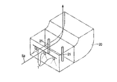
図8は、支柱21の防滴効果を示す構成図である。
FIG. 8 is a configuration diagram showing the drip-proof effect of the
支柱21の外周は、完全に一周するように、絶縁部材60で覆われる。絶縁部材60は、電気絶縁をする部材である。例えば、絶縁部材60は、ポリプロピレン、弗素樹脂、塩化ビニール、又は、ポリエチレンなどである。
The outer periphery of the
絶縁部材60で覆われていなければ、金属製である支柱21は、帯電した噴霧粒子を引き寄せる。一方、支柱21を覆う絶縁部材60は、帯電した噴霧粒子と同極性(正極)に帯電する。したがって、空気の流れSaに乗って噴霧粒子が支柱21に向かってきても、噴霧粒子の流れSgは、クーロン力により反発して離れていく。これにより、噴霧粒子による支柱21の濡れを抑制する。
If not covered with the insulating
支柱21の外周が絶縁部材60で完全に一周覆われていない場合、絶縁部材60が覆われていない箇所に集中して噴霧粒子が引き寄せられる。したがって、絶縁部材60は、支柱21の外周を一周以上して、重なる部分が出るぐらいの長さが望ましい。
When the outer periphery of the
図9は、支柱21の構成の具体例を示す構成図である。
FIG. 9 is a configuration diagram showing a specific example of the configuration of the
絶縁部材60は、ポリプロピレン製のフィルムである。絶縁部材60の厚さは、0.2mm以上が望ましいが、少なくとも0.1mm以上は必要である。絶縁部材60を支柱21の外周を1.5周程度巻く。このように、絶縁部材60が支柱21に巻かれた状態で、インシュロック61で固定する。
The insulating
また、循環ダクト20の内部の壁面及び床面などの表面も、支柱21と同様に、ポリプロピレン製のフィルムなどの絶縁部材60で覆うように隙間なく貼る。
Similarly to the
図10は、本実施形態に係る二流体ノズル1付近の構成を示す構成図である。
FIG. 10 is a configuration diagram showing a configuration near the two-
二流体ノズル1には、水供給路5及び空気供給路8が接続されている。水供給路5の材質は絶縁部材である。空気供給路8の材質は金属製である。したがって、空気供給路8は絶縁部材で覆う必要があり、水供給路5は絶縁部材で覆う必要はない。
A
次に、水供給路5を絶縁部材62で覆う方法について説明する。
Next, a method of covering the
絶縁部材62は、例えば、ポリプロピレン製の熱収縮するチューブである。
The insulating
絶縁部材62を熱収縮させずに空気供給路8に被せる。このとき、二流体ノズル1に空気供給路8を取り付けるためのニップルも覆うように被せる。なお、絶縁部材62は、空気供給路8の二流体ノズル1に近い部分にのみ被せれば、空気供給路8の全てを覆う必要はない。
The insulating
このように、流体噴霧システムの構成の一部で、濡らしたくない部位については、絶縁部材で覆う。その他に、流体噴霧システムの噴霧対象となる空間にあり、濡らしたくない物については絶縁部材で覆う。例えば、流体噴霧システムにより加湿を行う部屋で、水に弱い機器類は、絶縁部材で覆う。また、この部屋の内部の壁、柱、又は、床などを絶縁部材で覆ってもよい。なお、二流体ノズル1から噴霧された純水粒子は、空気中を漂う間に電荷を放出し、帯電していない状態になる。したがって、二流体ノズル1から一定以上離れた箇所は、絶縁部材で覆う必要はない。
As described above, a part of the configuration of the fluid spray system that does not want to get wet is covered with an insulating member. In addition, an object to be sprayed in the fluid spray system that is not to be wetted is covered with an insulating member. For example, in a room humidified by a fluid spray system, water-sensitive equipment is covered with an insulating member. Further, the wall, pillar, floor, or the like inside the room may be covered with an insulating member. The pure water particles sprayed from the two-
本実施形態によれば、防滴対象物を絶縁部材で覆うことで、二流体ノズル1から噴霧された帯電した噴霧粒子をクーロン力で反発させて、防滴対象物に付着するのを抑制することができる。
According to the present embodiment, by covering the drip-proof target with the insulating member, the charged spray particles sprayed from the two-
なお、本発明は上記実施形態そのままに限定されるものではなく、実施段階ではその要旨を逸脱しない範囲で構成要素を変形して具体化できる。また、上記実施形態に開示されている複数の構成要素の適宜な組み合わせにより、種々の発明を形成できる。例えば、実施形態に示される全構成要素から幾つかの構成要素を削除してもよい。さらに、異なる実施形態にわたる構成要素を適宜組み合わせてもよい。 It should be noted that the present invention is not limited to the above-described embodiments as they are, and can be embodied by modifying the constituent elements within a range not departing from the gist of the invention in an implementation stage. Further, various inventions can be formed by appropriately combining a plurality of constituent elements disclosed in the above-described embodiments. For example, some components may be deleted from all the components shown in the embodiment. Furthermore, the constituent elements of different embodiments may be combined appropriately.
Claims (5)
純水と比抵抗が1[MΩ・cm]を超える水とから成る群から選択した一つの水を供給する水供給源と、
前記圧縮空気供給源から供給される前記第一の圧縮空気をレギュレータで圧力制御することで第二の圧縮空気を生成し、前記第二の圧縮空気を前記水供給源から供給される前記水に溶解させることで前記水の導電率を調整する導電率調整手段と、
前記導電率調整手段により調整された前記水と前記圧縮空気供給源から供給された前記第一の圧縮空気を混合させて、霧化した流体を噴霧することで加湿を行う加湿用二流体ノズルと、
を備え、
前記水供給源から供給される前記水を蓄える第一タンクを備え、
前記導電率調整手段は、前記第二の圧縮空気を前記第一タンクの下側から入れることで、前記第二の圧縮空気を前記第一タンクの中の前記水に溶解させ、
前記水供給源から供給される前記水を蓄える第二タンクを備え、
前記導電率調整手段は、前記第一の圧縮空気を前記第二タンクの下側から入れることで前記第一の圧縮空気を前記第二タンクの中の前記水に溶解させ、
前記第一タンクは、前記第二タンクを介して前記第一の圧縮空気が溶解された前記水を取得するように構築された流体噴霧システム。 A compressed air supply source for supplying a first compressed air;
A water supply source for supplying one water selected from the group consisting of pure water and water having a specific resistance of more than 1 [MΩ · cm];
The second compressed air is generated by controlling the pressure of the first compressed air supplied from the compressed air supply source with a regulator, and the second compressed air is supplied to the water supplied from the water supply source. Conductivity adjusting means for adjusting the conductivity of the water by dissolving,
A two-fluid nozzle for humidification, which mixes the water adjusted by the conductivity adjusting unit with the first compressed air supplied from the compressed air supply source to perform humidification by spraying atomized fluid. ,
Equipped with
A first tank for storing the water supplied from the water supply source;
The conductivity adjusting means, by inserting the second compressed air from the lower side of the first tank, to dissolve the second compressed air in the water in the first tank,
A second tank for storing the water supplied from the water supply source,
The conductivity adjusting means dissolves the first compressed air in the water in the second tank by introducing the first compressed air from the lower side of the second tank,
Wherein the first tank, the flow body spray system constructed to obtain the water in which the first compressed air is dissolved through the second tank.
前記第二タンクの中の液面位置に応じて、前記第二タンクへの前記水の補給と補給停止とが自動的に実施され、
前記第一タンクの中の液面位置に応じて、前記第二タンクから前記第一タンクへの前記水の移送が自動的に実施されるように構築された請求項2に記載の流体噴霧システム。 A liquid level sensor is provided in the first tank and the second tank,
Depending on the liquid level position in the second tank, the replenishment and stoppage of the replenishment of the water to the second tank is automatically performed,
The fluid spray system according to claim 2 , wherein the water spray is constructed so that the transfer of the water from the second tank to the first tank is automatically performed according to the liquid surface position in the first tank. ..
Applications Claiming Priority (3)
| Application Number | Priority Date | Filing Date | Title |
|---|---|---|---|
| JP2016050199 | 2016-03-14 | ||
| JP2016050199 | 2016-03-14 | ||
| PCT/JP2017/010018 WO2017159630A1 (en) | 2016-03-14 | 2017-03-13 | Fluid spraying system |
Publications (2)
| Publication Number | Publication Date |
|---|---|
| JPWO2017159630A1 JPWO2017159630A1 (en) | 2018-12-13 |
| JP6696565B2 true JP6696565B2 (en) | 2020-05-20 |
Family
ID=59851013
Family Applications (1)
| Application Number | Title | Priority Date | Filing Date |
|---|---|---|---|
| JP2018505924A Active JP6696565B2 (en) | 2016-03-14 | 2017-03-13 | Fluid spray system |
Country Status (2)
| Country | Link |
|---|---|
| JP (1) | JP6696565B2 (en) |
| WO (1) | WO2017159630A1 (en) |
Families Citing this family (4)
| Publication number | Priority date | Publication date | Assignee | Title |
|---|---|---|---|---|
| JP6724747B2 (en) * | 2016-11-30 | 2020-07-15 | 東芝三菱電機産業システム株式会社 | Spray nozzle |
| JP7315953B2 (en) | 2019-07-29 | 2023-07-27 | 株式会社いけうち | Water spray method and water spray system |
| JP7214762B2 (en) * | 2021-02-05 | 2023-01-30 | 新日本空調株式会社 | Humidifying device, humidifier and humidifying method |
| JP7185972B1 (en) * | 2022-01-14 | 2022-12-08 | 株式会社キャスティングイン | spraying device |
Family Cites Families (7)
| Publication number | Priority date | Publication date | Assignee | Title |
|---|---|---|---|---|
| JPH02130921A (en) * | 1988-11-11 | 1990-05-18 | Taiyo Sanso Co Ltd | Cleaning equipment for solid surface |
| JP3702762B2 (en) * | 2000-07-27 | 2005-10-05 | 日立プラント建設株式会社 | Humidification method and humidifier |
| JP2003154242A (en) * | 2001-11-26 | 2003-05-27 | Texas Instr Japan Ltd | Fluid mixing apparatus |
| JP2006223995A (en) * | 2005-02-17 | 2006-08-31 | Sony Corp | Washing method and washing device |
| WO2006137410A1 (en) * | 2005-06-21 | 2006-12-28 | Nikon Corporation | Exposure apparatus, exposure method, maintenance method and device manufacturing method |
| JP2011236867A (en) * | 2010-05-13 | 2011-11-24 | Hino Motors Ltd | Fuel spray nozzle |
| JP6007294B2 (en) * | 2015-08-03 | 2016-10-12 | 東芝三菱電機産業システム株式会社 | Two-fluid spraying device |
-
2017
- 2017-03-13 WO PCT/JP2017/010018 patent/WO2017159630A1/en active Application Filing
- 2017-03-13 JP JP2018505924A patent/JP6696565B2/en active Active
Also Published As
| Publication number | Publication date |
|---|---|
| WO2017159630A1 (en) | 2017-09-21 |
| JPWO2017159630A1 (en) | 2018-12-13 |
Similar Documents
| Publication | Publication Date | Title |
|---|---|---|
| JP6696565B2 (en) | Fluid spray system | |
| KR100915213B1 (en) | A system and method for controlling direct-spraying humidifier in a clean room | |
| US10363497B2 (en) | Devices, systems, and methods for controlled delivery of process gases | |
| US20110236730A1 (en) | Battery watering system | |
| CA2867883A1 (en) | Method of delivering a process gas from a multi-component solution | |
| JP2020518951A (en) | Integrated hydrogen recycling system using a pressurized multi-chamber tank | |
| US10508820B2 (en) | Device for producing water droplets for air humidification and a humidification system with such devices | |
| CN203102030U (en) | Foam mixing control system based on CAN (controller area network) bus for fire-fighting truck | |
| CN208082077U (en) | A kind of micro- mist system | |
| KR102175708B1 (en) | Gas humidity control method and regulator | |
| JP4243154B2 (en) | Slurry supply method | |
| CN106032923A (en) | Multifunctional humidifier | |
| KR102353490B1 (en) | Plenum moisturizing system | |
| CN207849599U (en) | Large Central Air Conditioning System assists warming and wetting apparatus | |
| KR102441847B1 (en) | Activation apparatus for fuel cell and humidifier thereof | |
| JP2015085316A (en) | Equipment for producing hydrogen-containing solution | |
| JP2008075943A (en) | Humidifier | |
| WO1988008125A1 (en) | Air stream visualization apparatus | |
| CN109960299B (en) | Humidification module of high-power fuel cell stack tester | |
| JP6777533B2 (en) | Diluting solution manufacturing equipment and diluent manufacturing method | |
| US20170013797A1 (en) | Cage system comprising a climate control unit having a low flow vaporizer | |
| WO2018123193A1 (en) | Device for manufacturing diluted liquid, and method for manufacturing diluted liquid | |
| TW397803B (en) | Dispensing system and method for dispensing an aqueous solution | |
| CN113731146A (en) | Wet washing device and cooling method during flue gas washing | |
| JP2010063960A (en) | Atomizer |
Legal Events
| Date | Code | Title | Description |
|---|---|---|---|
| A621 | Written request for application examination |
Free format text: JAPANESE INTERMEDIATE CODE: A621 Effective date: 20180813 |
|
| A131 | Notification of reasons for refusal |
Free format text: JAPANESE INTERMEDIATE CODE: A131 Effective date: 20190604 |
|
| A521 | Request for written amendment filed |
Free format text: JAPANESE INTERMEDIATE CODE: A523 Effective date: 20190712 |
|
| A02 | Decision of refusal |
Free format text: JAPANESE INTERMEDIATE CODE: A02 Effective date: 20200107 |
|
| A521 | Request for written amendment filed |
Free format text: JAPANESE INTERMEDIATE CODE: A523 Effective date: 20200221 |
|
| A911 | Transfer to examiner for re-examination before appeal (zenchi) |
Free format text: JAPANESE INTERMEDIATE CODE: A911 Effective date: 20200303 |
|
| TRDD | Decision of grant or rejection written | ||
| A01 | Written decision to grant a patent or to grant a registration (utility model) |
Free format text: JAPANESE INTERMEDIATE CODE: A01 Effective date: 20200324 |
|
| A61 | First payment of annual fees (during grant procedure) |
Free format text: JAPANESE INTERMEDIATE CODE: A61 Effective date: 20200406 |
|
| R150 | Certificate of patent or registration of utility model |
Ref document number: 6696565 Country of ref document: JP Free format text: JAPANESE INTERMEDIATE CODE: R150 |
|
| R250 | Receipt of annual fees |
Free format text: JAPANESE INTERMEDIATE CODE: R250 |
|
| R250 | Receipt of annual fees |
Free format text: JAPANESE INTERMEDIATE CODE: R250 |