JP6692762B2 - Torque sensor - Google Patents
Torque sensor Download PDFInfo
- Publication number
- JP6692762B2 JP6692762B2 JP2017023885A JP2017023885A JP6692762B2 JP 6692762 B2 JP6692762 B2 JP 6692762B2 JP 2017023885 A JP2017023885 A JP 2017023885A JP 2017023885 A JP2017023885 A JP 2017023885A JP 6692762 B2 JP6692762 B2 JP 6692762B2
- Authority
- JP
- Japan
- Prior art keywords
- bridge circuit
- strain sensor
- sensor
- circuit
- output voltage
- Prior art date
- Legal status (The legal status is an assumption and is not a legal conclusion. Google has not performed a legal analysis and makes no representation as to the accuracy of the status listed.)
- Active
Links
- 230000005856 abnormality Effects 0.000 claims description 32
- 238000001514 detection method Methods 0.000 claims description 29
- 239000002184 metal Substances 0.000 claims description 10
- 238000006243 chemical reaction Methods 0.000 description 11
- 230000002159 abnormal effect Effects 0.000 description 5
- 239000000470 constituent Substances 0.000 description 3
- 238000010586 diagram Methods 0.000 description 3
- 239000003638 chemical reducing agent Substances 0.000 description 2
- 230000000694 effects Effects 0.000 description 2
- 238000003466 welding Methods 0.000 description 2
- 239000010408 film Substances 0.000 description 1
- 238000004519 manufacturing process Methods 0.000 description 1
- 239000000463 material Substances 0.000 description 1
- 239000010409 thin film Substances 0.000 description 1
Images


Classifications
-
- G—PHYSICS
- G01—MEASURING; TESTING
- G01L—MEASURING FORCE, STRESS, TORQUE, WORK, MECHANICAL POWER, MECHANICAL EFFICIENCY, OR FLUID PRESSURE
- G01L25/00—Testing or calibrating of apparatus for measuring force, torque, work, mechanical power, or mechanical efficiency
- G01L25/003—Testing or calibrating of apparatus for measuring force, torque, work, mechanical power, or mechanical efficiency for measuring torque
-
- B—PERFORMING OPERATIONS; TRANSPORTING
- B25—HAND TOOLS; PORTABLE POWER-DRIVEN TOOLS; MANIPULATORS
- B25J—MANIPULATORS; CHAMBERS PROVIDED WITH MANIPULATION DEVICES
- B25J13/00—Controls for manipulators
- B25J13/08—Controls for manipulators by means of sensing devices, e.g. viewing or touching devices
- B25J13/085—Force or torque sensors
-
- G—PHYSICS
- G01—MEASURING; TESTING
- G01L—MEASURING FORCE, STRESS, TORQUE, WORK, MECHANICAL POWER, MECHANICAL EFFICIENCY, OR FLUID PRESSURE
- G01L3/00—Measuring torque, work, mechanical power, or mechanical efficiency, in general
- G01L3/02—Rotary-transmission dynamometers
- G01L3/04—Rotary-transmission dynamometers wherein the torque-transmitting element comprises a torsionally-flexible shaft
- G01L3/10—Rotary-transmission dynamometers wherein the torque-transmitting element comprises a torsionally-flexible shaft involving electric or magnetic means for indicating
- G01L3/108—Rotary-transmission dynamometers wherein the torque-transmitting element comprises a torsionally-flexible shaft involving electric or magnetic means for indicating involving resistance strain gauges
-
- G—PHYSICS
- G01—MEASURING; TESTING
- G01L—MEASURING FORCE, STRESS, TORQUE, WORK, MECHANICAL POWER, MECHANICAL EFFICIENCY, OR FLUID PRESSURE
- G01L5/00—Apparatus for, or methods of, measuring force, work, mechanical power, or torque, specially adapted for specific purposes
- G01L5/0028—Force sensors associated with force applying means
- G01L5/0042—Force sensors associated with force applying means applying a torque
-
- G—PHYSICS
- G01—MEASURING; TESTING
- G01L—MEASURING FORCE, STRESS, TORQUE, WORK, MECHANICAL POWER, MECHANICAL EFFICIENCY, OR FLUID PRESSURE
- G01L5/00—Apparatus for, or methods of, measuring force, work, mechanical power, or torque, specially adapted for specific purposes
- G01L5/0061—Force sensors associated with industrial machines or actuators
- G01L5/0071—Specific indicating arrangements, e.g. of overload
Landscapes
- Physics & Mathematics (AREA)
- General Physics & Mathematics (AREA)
- Engineering & Computer Science (AREA)
- Chemical & Material Sciences (AREA)
- Analytical Chemistry (AREA)
- Human Computer Interaction (AREA)
- Robotics (AREA)
- Mechanical Engineering (AREA)
- Force Measurement Appropriate To Specific Purposes (AREA)
- Measurement Of Length, Angles, Or The Like Using Electric Or Magnetic Means (AREA)
- Transmission And Conversion Of Sensor Element Output (AREA)
Description
本発明の実施形態は、例えばロボットアームの関節に設けられるトルクセンサに関する。 Embodiments of the present invention relate to a torque sensor provided at a joint of a robot arm, for example.
例えば製造ラインにおいて、複数のロボットアームが設置され、これらロボットアームが協働して製品の組み立てが行われている。これらロボットアームの関節には、トルクセンサが設けられている(例えば特許文献1、2、3参照)。
For example, in a manufacturing line, a plurality of robot arms are installed, and these robot arms cooperate to assemble a product. Torque sensors are provided at the joints of these robot arms (see, for example,
従来、ロボットアームに装着されるトルクセンサは、トルクセンサ自体の異常や、アームの異常を検出することが困難であった。このため、例えば複数のロボットアームが協働する協働ロボットにおいて、何らかの原因によりトルクセンサ自体の異常や、アームの異常が発生した場合においても、ロボットアーム同士の衝突などを回避することが困難であった。したがって、トルクセンサ自体の異常を事前に検知することが可能な所謂フェイルセーフ機能を有するトルクセンサが要望されている。 Conventionally, it has been difficult for a torque sensor mounted on a robot arm to detect an abnormality of the torque sensor itself or an abnormality of the arm. For this reason, for example, in a collaborative robot in which a plurality of robot arms collaborate, it is difficult to avoid collision between robot arms even when abnormality of the torque sensor itself or abnormality of the arm occurs for some reason. there were. Therefore, there is a demand for a torque sensor having a so-called fail-safe function that can detect an abnormality of the torque sensor itself in advance.
本発明の実施形態は、トルクセンサ自体の異常を検出することができ、フェイルセーフ機能を有するトルクセンサを提供する。 Embodiments of the present invention provide a torque sensor capable of detecting an abnormality in the torque sensor itself and having a fail-safe function.
本実施形態のトルクセンサは、被計測体に連結される第1構造体と、第2構造体と、前記第1構造体と前記第2構造体との間に伝達される力を検出する複数の歪センサを含む第1ブリッジ回路と、前記第1構造体と前記第2構造体との間に伝達される力を検出する複数の歪センサを含む第2ブリッジ回路と、前記第1ブリッジ回路の第1出力電圧と前記第2ブリッジ回路の第2出力電圧との差が第1閾値電圧を超えた場合、異常検出信号を出力するコントローラと、前記複数の歪センサのそれぞれが設けられた金属板のそれぞれを、前記第1構造体と前記第2構造体との間に固定する複数のネジと、を具備する。 The torque sensor according to the present embodiment includes a plurality of first structures that are coupled to the object to be measured, a second structure, and a plurality of forces that detect forces transmitted between the first structure and the second structure. Bridge circuit including a strain sensor, a second bridge circuit including a plurality of strain sensors for detecting a force transmitted between the first structure and the second structure, and the first bridge circuit When a difference between the first output voltage and the second output voltage of the second bridge circuit exceeds a first threshold voltage, a controller that outputs an abnormality detection signal, and a metal provided with each of the plurality of strain sensors A plurality of screws for fixing each of the plates between the first structure and the second structure .
以下、実施の形態について、図面を参照して説明する。図面において、同一部分には同一符号を付している。 Hereinafter, embodiments will be described with reference to the drawings. In the drawings, the same parts are designated by the same reference numerals.
(第1の実施形態)
図1において、トルクセンサ10は、例えば第1構造体11、第2構造体12、梁部としての複数の第3構造体13、第1ブリッジ回路B1、及び第2ブリッジ回路B2を具備している。
(First embodiment)
In FIG. 1, the
第1構造体11及び第2構造体12は、例えば環状であり、第2構造体12は、第1構造体11に同心状に配置されている。複数の第3構造体13a、13b、13c、13dは、第1構造体11と第2構造体12を連結する。第1の実施形態において、第3構造体13a、13b、13c、13dは、例えば起歪部として機能する。
The
第1構造体11は、被計測体としての例えば図示せぬロボットアームの関節の一方に取着される。具体的には、第1構造体11は、例えば図示せぬ減速機に取着され、減速機は図示せぬモータに連結される。第2構造体12は、例えば図示せぬロボットアームの関節の他方に取着される。
The
第3構造体13a、13b、13c、13dは、第1構造体11と第2構造体12間において、力(トルク)を伝達する。
The
第1構造体11、第2構造体12、第3構造体13a、13b、13c、13dは、例えば金属により構成されている。しかし、印加されるトルクに対して十分な機械的強度を得ることができれば、金属以外の材料により第1構造体11、第2構造体12、第3構造体13a、13b、13c、13dを構成することも可能である。
The
第3構造体13a、13b、13c、13dのうち、例えば180°離れた位置に配置された第3構造体13a、13cには、第1ブリッジ回路B1と、第2ブリッジ回路B2が設けられる。
Of the
第1ブリッジ回路B1は、第1歪センサ(歪ゲージ)G1〜第4歪センサG4により構成され、第2ブリッジ回路B2は、第5歪センサG5〜第8歪センサG8により構成されている。 The first bridge circuit B1 includes first strain sensor (strain gauge) G1 to fourth strain sensor G4, and the second bridge circuit B2 includes fifth strain sensor G5 to eighth strain sensor G8.
第1ブリッジ回路B1の第1歪センサG1、第2歪センサG2、及び第2ブリッジ回路B2の第5歪センサG5、第6歪センサG6は、第3構造体13aに設けられ、第1ブリッジ回路B1の第3歪センサG3、第4歪センサG4、及び第2ブリッジ回路B2の第7歪センサG7、第8歪センサG8は、第3構造体13cに設けられている。
The first strain sensor G1 and the second strain sensor G2 of the first bridge circuit B1 and the fifth strain sensor G5 and the sixth strain sensor G6 of the second bridge circuit B2 are provided in the
第1歪センサG1〜第8歪センサG8は、例えば図示せぬ金属板上に絶縁膜を介して設けられた例えば薄膜抵抗体により構成されている。しかし、第1歪センサG1〜第8歪センサG8の構成は、これに限定されるものではない。 The first strain sensor G1 to the eighth strain sensor G8 are composed of, for example, thin film resistors provided on a metal plate (not shown) via an insulating film. However, the configurations of the first strain sensor G1 to the eighth strain sensor G8 are not limited to this.
第1歪センサG1〜第8歪センサG8の金属板は、例えば接着、ネジ締結又は溶接などの手段を用いて第3構造体13a又は第3構造体13cの表面に固定される。
The metal plates of the first strain sensor G1 to the eighth strain sensor G8 are fixed to the surface of the
また、第1歪センサG1、第2歪センサG2、第5歪センサG5、第6歪センサG6を、第3構造体13aに設け、第3歪センサG3、第4歪センサG4、第7歪センサG7、第8歪センサG8を、第3構造体13cに設けたが、これに限定されるものではない。
Further, the first strain sensor G1, the second strain sensor G2, the fifth strain sensor G5, and the sixth strain sensor G6 are provided in the
例えば、第1歪センサG1〜第8歪センサG8に設けられた金属板を起歪体として用い、第3構造体13a、13b、13c、13d以外の場所で、第1歪センサG1、第2歪センサG2、第5歪センサG5、第6歪センサG6の金属板を、第1構造体11と第2構造体12との間に架け渡し、第3歪センサG3、第4歪センサG4、第7歪センサG7、第8歪センサG8の金属板を、第1構造体11と第2構造体12との間に架け渡す構成としてもよい。各歪センサの金属板は、第1構造体11と第2構造体12に、例えば接着、ネジ締結又は溶接などの手段を用いて固定すればよい。
For example, the metal plate provided in the first strain sensor G1 to the eighth strain sensor G8 is used as a strain generating body, and the first strain sensor G1 The metal plates of the strain sensor G2, the fifth strain sensor G5, and the sixth strain sensor G6 are bridged between the
第1ブリッジ回路B1において、第1歪センサG1と第3歪センサG3は直列接続され、第2歪センサG2と第4歪センサG4は、直列接続されている。直列接続された第1歪センサG1と第3歪センサG3は、直列接続された第2歪センサG2と第4歪センサG4に並列接続されている。 In the first bridge circuit B1, the first strain sensor G1 and the third strain sensor G3 are connected in series, and the second strain sensor G2 and the fourth strain sensor G4 are connected in series. The first strain sensor G1 and the third strain sensor G3 connected in series are connected in parallel to the second strain sensor G2 and the fourth strain sensor G4 connected in series.
第2歪センサG2と第4歪センサG4との接続ノードに電源Vo、例えば5Vが供給され、第1歪センサG1と第3歪センサG3との接続ノードは、接地されている。 The connection node between the second strain sensor G2 and the fourth strain sensor G4 is supplied with the power source Vo, for example, 5V, and the connection node between the first strain sensor G1 and the third strain sensor G3 is grounded.
第2ブリッジ回路B2において、第5歪センサG5と第7歪センサG7は直列接続され、第6歪センサG6と第8歪センサG8は、直列接続されている。直列接続された第5歪センサG5と第7歪センサG7は、直列接続された第6歪センサG6と第8歪センサG8に並列接続されている。 In the second bridge circuit B2, the fifth strain sensor G5 and the seventh strain sensor G7 are connected in series, and the sixth strain sensor G6 and the eighth strain sensor G8 are connected in series. The fifth strain sensor G5 and the seventh strain sensor G7 connected in series are connected in parallel to the sixth strain sensor G6 and the eighth strain sensor G8 connected in series.
第6歪センサG6と第8歪センサG8との接続ノードに電源Vo、例えば5Vが供給され、第5歪センサG5と第7歪センサG7との接続ノードは、接地されている。 The connection node between the sixth strain sensor G6 and the eighth strain sensor G8 is supplied with the power source Vo, for example, 5V, and the connection node between the fifth strain sensor G5 and the seventh strain sensor G7 is grounded.
第1ブリッジ回路B1において、第1歪センサG1と第2歪センサG2との接続ノードは第1電圧検出回路15の一端部に接続され、第3歪センサG3と第4歪センサG4との接続ノードは第1電圧検出回路15の他端部に接続されている。
In the first bridge circuit B1, the connection node between the first strain sensor G1 and the second strain sensor G2 is connected to one end of the first
第2ブリッジ回路B2において、第5歪センサG5と第6歪センサG6との接続ノードは第2電圧検出回路16の一端部に接続され、第7歪センサG7と第8歪センサG8との接続ノードは第2電圧検出回路16の他端部に接続されている。
In the second bridge circuit B2, the connection node between the fifth strain sensor G5 and the sixth strain sensor G6 is connected to one end of the second
第1電圧検出回路15は、第1ブリッジ回路B1の出力電圧を検出し、第2電圧検出回路16は、第2ブリッジ回路B2の出力電圧を検出する。第1電圧検出回路15及び第2電圧検出回路16は、例えば分圧抵抗と演算増幅器により構成される。しかし、これに限定されるものではない。
The first
第1電圧検出回路15の動作原理は、次の通りである。
The operating principle of the first
例えばトルクセンサ10にトルク(第1構造体11、第2構造体12の時計回り方向又は反時計回り方向)が印加された場合、第1ブリッジ回路B1において、第1歪センサG1と第2歪センサG2の接続点から出力電圧Vout+が出力され、第3歪センサG3と第4歪センサG4の接続点から出力電圧Vout-が出力される。出力電圧Vout+及び出力電圧Vout-から式(1)で示す第1ブリッジ回路B1の出力電圧Vout1が得られる。
For example, when torque (clockwise direction or counterclockwise direction of the
Vout1=(Vout+−Vout-)
=(R1/(R1+R2)−R3/(R3+R4))・Vo …(1)
ここで、
R1は、第1歪センサG1の抵抗値
R2は、第2歪センサG2の抵抗値
R3は、第3歪センサG3の抵抗値
R4は、第4歪センサG4の抵抗値
であり、トルクセンサ10にトルクが印加されていない状態において、R1=R2=R3=R4=Rである。
Vout1 = (Vout + -Vout-)
= (R1 / (R1 + R2) -R3 / (R3 + R4)) * Vo (1)
here,
R1 is the resistance value of the first strain sensor G1, R2 is the resistance value of the second strain sensor G2, R3 is the resistance value of the third strain sensor G3, R4 is the resistance value of the fourth strain sensor G4, and
一方、トルクセンサ10にトルク以外の力、例えばスラスト力(図1に示す第1構造体11、第2構造体12に対する左右方向(X方向)の力、又は、上下方向(Y方向)の力)が加わった場合、第1歪センサG1、第2歪センサG2、第3歪センサG3及び第4歪センサG4の抵抗値の変化(R1=R−ΔR、R2=R+ΔR、R3=R−ΔR、R4=R+ΔR、ここで、ΔRは、抵抗値の変化の値)が相殺され、第1ブリッジ回路B1の出力電圧Vout1は、0Vとなる。
On the other hand, a force other than torque is applied to the
第2ブリッジ回路B2に対応する第2電圧検出回路16の動作原理も第1電圧検出回路15と同様である。第2電圧検出回路16の出力電圧Vout2も第1電圧検出回路15と同様にして得られる。
The operation principle of the second
第1電圧検出回路15の出力電圧Vout1は、アナログデジタル(AD)変換回路17に供給されてデジタル信号に変換され、第2電圧検出回路16出力電圧Vout2は、AD変換回路18に供給されてデジタル信号に変換される。AD変換回路17及びAD変換回路18の出力信号(以下、第1ブリッジ回路B1及び第2ブリッジ回路B2の出力信号とも言う)は、例えば定期的にコントローラ19に供給される。コントローラ19は、AD変換回路17及びAD変換回路18の出力信号の一方又は両方を、トルクセンサ10の出力信号として外部の装置に供給したり、後述するトルクセンサ10の異常を検知したりする。
The output voltage Vout1 of the first
また、コントローラ19は、AD変換回路17及びAD変換回路18の出力信号を例えば一定期間記憶することが可能な記憶部20を具備している。記憶部20に記憶されたAD変換回路17及びAD変換回路18の出力信号は、例えば一定期間毎に更新される。
The
さらに、コントローラ19には、例えば表示装置21が接続されている。表示装置21は、トルクセンサ10の検出出力信号やトルクセンサ10の異常が検出されたことを示す信号などを表示する。
Further, for example, a
(動作)
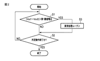
図2、図3は、コントローラ19の動作を説明するためのフローチャートである。
(motion)
2 and 3 are flowcharts for explaining the operation of the
トルクセンサ10は、通常時、第1ブリッジ回路B1と第2ブリッジ回路B2との両方が同時に動作しており、第1ブリッジ回路B1と第2ブリッジ回路B2の出力電圧が比較されている。すなわち、コントローラ19は、第1電圧検出回路15からAD変換回路17を介して供給される第1ブリッジ回路B1の出力電圧Vout1と、第2電圧検出回路16からAD変換回路18を介して供給される第2ブリッジ回路B2の出力電圧Vout2との差の絶対値を求め、この差の絶対値と第1閾値電圧とを比較する(S1)。尚、絶対値は必ずしも必要なく、両出力電圧の差が求められればよい。
In the
上記比較の結果、差の絶対値が第1閾値電圧より小さい場合(S1、NO)、第1ブリッジ回路B1と第2ブリッジ回路B2の両方は、正常に動作していると判断される。コントローラ19は、第1ブリッジ回路B1と第2ブリッジ回路B2の例えば一方の出力電圧に基づきトルクセンサ10の所定の動作が終了したかどうかを判断する(S2)。所定の動作とは、前述したように、例えばトルクセンサ10の出力信号を外部の装置に供給したり、トルクセンサ10の異常を検知したりするなどの動作である。この判断の結果、所定の動作が終了していない場合(S2、NO)、制御がS1に移行される。また、所定の動作が終了している場合(S2、YES)、制御が終了される。
As a result of the comparison, when the absolute value of the difference is smaller than the first threshold voltage (S1, NO), it is determined that both the first bridge circuit B1 and the second bridge circuit B2 are operating normally. The
一方、S1において、差の絶対値が第1閾値電圧より大きいと判断された場合(S1、YES)、制御が異常処理ルーチンS3に移行される。すなわち、差の絶対値が第1閾値電圧より大きいということは、第1ブリッジ回路B1と第2ブリッジ回路B2のいずれかに異常が発生したことを意味している。このため、異常処理ルーチンS3において、第1ブリッジ回路B1と第2ブリッジ回路B2のどちらに異常が発生しているかが判別される。 On the other hand, if it is determined in S1 that the absolute value of the difference is larger than the first threshold voltage (S1, YES), the control proceeds to the abnormality processing routine S3. That is, the absolute value of the difference being larger than the first threshold voltage means that an abnormality has occurred in either the first bridge circuit B1 or the second bridge circuit B2. Therefore, in the abnormality processing routine S3, it is determined which of the first bridge circuit B1 and the second bridge circuit B2 has an abnormality.
図3は、異常処理ルーチンS3の一例を示している。 FIG. 3 shows an example of the abnormality processing routine S3.
先ず、コントローラ19は、第1ブリッジ回路B1の出力電圧Vout1と記憶部20に記憶された第1ブリッジ回路B1の前回の出力電圧Vout11との差の絶対値を求め、この絶対値が第2閾値電圧より高いかどうかを判断する(S31)。第2閾値電圧は、第1閾値電圧と同等又は第1閾値電圧以下であってもよい。
First, the
この判別の結果、差の絶対値が第2閾値電圧より大きい場合(S31、YES)、第1ブリッジ回路B1は異常と判断され、例えば第1ブリッジ回路B1への電源供給が停止されるとともに、表示装置21に第1ブリッジ回路B1が異常であることが表示される(S32)。この後、制御が例えばS2に移行され、正常な第2ブリッジ回路B2を用いて所定の動作が実行される。
As a result of this determination, when the absolute value of the difference is larger than the second threshold voltage (S31, YES), the first bridge circuit B1 is determined to be abnormal, and for example, the power supply to the first bridge circuit B1 is stopped, and The
一方、絶対値が第2閾値電圧以下である場合、第1ブリッジ回路B1は正常と判断され(S31、YES)、コントローラ19は、第2ブリッジ回路B2の出力電圧Vout2と記憶部20に記憶された第2ブリッジ回路B2の前回の出力電圧Vout21との差の絶対値を求め、この差の絶対値が第2閾値電圧より高いかどうかを判断する(S33)。
On the other hand, when the absolute value is equal to or lower than the second threshold voltage, the first bridge circuit B1 is determined to be normal (S31, YES), and the
この判別の結果、差の絶対値が第2閾値電圧より大きい場合(S33、YES)、第2ブリッジ回路B2は異常と判断され、例えば第2ブリッジ回路B2への電源供給が停止されるとともに、表示装置21に第2ブリッジ回路B2が異常であることが表示される(S34)。この後、制御が例えばS2に移行され、正常な第1ブリッジ回路B1を用いて所定の動作が実行される。
As a result of this determination, when the absolute value of the difference is larger than the second threshold voltage (S33, YES), the second bridge circuit B2 is determined to be abnormal, and for example, the power supply to the second bridge circuit B2 is stopped, and The
また、S33において、差の絶対値が第2閾値電圧以下と判断された場合(S33、NO)、今回の判断において、第1ブリッジ回路B1と第2ブリッジ回路B2のいずれにも異常が検出されなかったと判断される。このような結果が出る場合は、トルクセンサ10以外に異常が発生しているなどの原因が考えられる。このため、S33において、絶対値が第2閾値電圧以下と判断された場合(S33、NO)、例えば表示装置21に異常が発生したことが表示される(S35)。この後、制御がS2に移行される。
If it is determined in S33 that the absolute value of the difference is less than or equal to the second threshold voltage (S33, NO), an abnormality is detected in both the first bridge circuit B1 and the second bridge circuit B2 in this determination. It is judged that there was not. When such a result is obtained, it is considered that a cause other than the
このように、異常処理ルーチンS3において、第1ブリッジ回路B1と第2ブリッジ回路B2との一方に異常が検出された場合、異常が検出された第1ブリッジ回路B1及び第2ブリッジ回路B2の一方が停止され、正常な第1ブリッジ回路B1及び第2ブリッジ回路B2の他方を用いてトルクセンサ10の動作が継続される。
Thus, in the abnormality processing routine S3, when an abnormality is detected in one of the first bridge circuit B1 and the second bridge circuit B2, one of the first bridge circuit B1 and the second bridge circuit B2 in which the abnormality is detected is detected. Is stopped, and the operation of the
しかし、異常処理ルーチンは、これに限定されるものではなく、S1において、異常が検出された場合、直ちに第1ブリッジ回路B1及び第2ブリッジ回路B2を停止させ、表示装置21にトルクセンサ10に異常が発生したことを表示させてもよい。
However, the abnormality processing routine is not limited to this, and when an abnormality is detected in S1, the first bridge circuit B1 and the second bridge circuit B2 are immediately stopped, and the
上記第1の実施形態によれば、トルクセンサ10は、第1ブリッジ回路B1と第2ブリッジ回路B2を具備し、第1ブリッジ回路B1の出力電圧と第2ブリッジ回路B2の出力電圧の差(の絶対値)が第1閾値電圧を超えた場合、第1ブリッジ回路B1と第2ブリッジ回路B2の一方に異常が発生したものと判断している。このため、第1ブリッジ回路B1と第2ブリッジ回路B2の両方が故障する以前にトルクセンサ10の異常を検出することが可能である。したがった、トルクセンサ10は、フェイルセーフ機能を有し、トルクセンサ10が装着されるロボットアームの衝突等の発生を未然に防止することが可能である。
According to the first embodiment, the
また、第1ブリッジ回路B1又は第2ブリッジ回路B2に異常が発生した場合、異常が発生したブリッジ回路を特定して停止させ、正常なブリッジ回路を用いて動作を継続することが可能である。このため、正常なブリッジ回路を用いてトルクセンサ10を継続して動作させることができ、ロボットアームを例えば安全な位置に移動させた後に停止させるなどの制御を行うことが可能である。
Further, when an abnormality occurs in the first bridge circuit B1 or the second bridge circuit B2, it is possible to identify the bridge circuit in which the abnormality has occurred and stop it, and continue the operation using a normal bridge circuit. Therefore, the
(第2の実施形態)
第1の実施形態において、第1ブリッジ回路B1と第2ブリッジ回路B2は、共に第1構造体13aと13cに設けた。すなわち、第1ブリッジ回路B1と第2ブリッジ回路B2は、並行に配置されていた。
(Second embodiment)
In the first embodiment, both the first bridge circuit B1 and the second bridge circuit B2 are provided in the
これに対して、第2の実施形態において、第1ブリッジ回路Bと第2ブリッジ回路B2は、交差して配置される。 On the other hand, in the second embodiment, the first bridge circuit B and the second bridge circuit B2 are arranged to intersect with each other.
図4は、第2の実施形態の一例を示している。 FIG. 4 shows an example of the second embodiment.
図4に示すように、第1ブリッジ回路B1の第1歪センサG1と第2歪センサG2は、第3構造体13aに配置され、第1ブリッジ回路B1の第3歪センサG3と第4歪センサG4は、第3構造体13cに配置される。
As shown in FIG. 4, the first strain sensor G1 and the second strain sensor G2 of the first bridge circuit B1 are arranged in the
また、第2ブリッジ回路B2の第5歪センサG5と第6歪センサG6は、第3構造体13bに配置され、第2ブリッジ回路B2の第7歪センサG7と第8歪センサG8は、第3構造体13dに配置される。
Further, the fifth strain sensor G5 and the sixth strain sensor G6 of the second bridge circuit B2 are arranged in the
第2の実施形態において、回路構成及び動作は、第1の実施形態と同様である。 The circuit configuration and operation of the second embodiment are similar to those of the first embodiment.
第2の実施形態によっても第1の実施形態と同様の効果を得ることが可能である。 The same effects as those of the first embodiment can be obtained by the second embodiment.
しかも、第2の実施形態によれば、第1ブリッジ回路B1と第2ブリッジ回路B2を交差して配置し、第1ブリッジ回路B1の第1歪センサG1〜第4歪センサG4を第3構造体13a、13cに配置し、第2ブリッジ回路B2の第5歪センサG5〜第8歪センサG8を第3構造体13a、13cとは別の第3構造体13b、13dに配置することにより、第1ブリッジ回路B1と第2ブリッジ回路B2が同時に故障する確率を低減させることが可能である。
Moreover, according to the second embodiment, the first bridge circuit B1 and the second bridge circuit B2 are arranged so as to cross each other, and the first strain sensor G1 to the fourth strain sensor G4 of the first bridge circuit B1 have the third structure. By disposing the fifth strain sensor G5 to the eighth strain sensor G8 of the second bridge circuit B2 in the
(第3の実施形態)
第1、第2の実施形態において、第1ブリッジ回路B1及び第2ブリッジ回路B2の異常は、デジタル信号をベースとして検出した。しかし、これに限らず、アナログ信号をベースとして検出することも可能である。
(Third Embodiment)
In the first and second embodiments, the abnormality of the first bridge circuit B1 and the second bridge circuit B2 is detected based on the digital signal. However, the present invention is not limited to this, and it is also possible to detect based on an analog signal.
図5は、第3の実施形態の一例を示している。 FIG. 5 shows an example of the third embodiment.
第3の実施形態において、第1ブリッジ回路B1と第2ブリッジ回路B2の配置は、第1の実施形態と同様に平行に配置されているが、第2の実施形態のように、交差して配置してもよい。 In the third embodiment, the first bridge circuit B1 and the second bridge circuit B2 are arranged in parallel as in the first embodiment, but they are arranged in the same manner as in the second embodiment. You may arrange.
第1ブリッジ回路B1の出力電圧Vout+、Vout-は、第1電圧検出回路15に供給され、第2ブリッジ回路B2の出力電圧Vout+、Vout-は、第2電圧検出回路16に供給される。第1電圧検出回路15の出力電圧Vout1と、第2電圧検出回路16の出力電圧Vout2は、減算回路22に供給される。減算回路22は、第1電圧検出回路15の出力電圧Vout1と、第2電圧検出回路16の出力電圧Vout2との差の電圧を出力する。減算回路22の出力電圧は、比較回路23に供給され、比較回路23において、第1閾値電圧24と比較される。比較回路23の比較結果はコントローラ19に供給される。コントローラ19は、比較回路23の比較結果が異常を示す場合、例えば第1ブリッジ回路B1、第2ブリッジ回路B2への電源供給を停止するとともに、例えばロボットアームの動作を停止させる。或いは、コントローラ19は、第1の実施形態のように、第1ブリッジ回路B1、第2ブリッジ回路B2のうちのどちらに異常が発生したかを検出するように構成することも可能である。
The output voltages Vout + and Vout− of the first bridge circuit B1 are supplied to the first
第3の実施形態によっても第1、第2の実施形態と同様の効果を得ることが可能である。しかも、アナログ信号ベースで処理することにより、処理速度を高速化することが可能である。 The same effects as those of the first and second embodiments can also be obtained by the third embodiment. Moreover, the processing speed can be increased by processing on the basis of the analog signal.
その他、本発明は上記各実施形態そのままに限定されるものではなく、実施段階ではその要旨を逸脱しない範囲で構成要素を変形して具体化できる。また、上記各実施形態に開示されている複数の構成要素の適宜な組み合わせにより、種々の発明を形成できる。例えば、実施形態に示される全構成要素から幾つかの構成要素を削除してもよい。さらに、異なる実施形態にわたる構成要素を適宜組み合わせてもよい。 In addition, the present invention is not limited to the above-described embodiments as they are, and can be embodied by modifying the constituent elements within a range not departing from the gist of the invention in an implementation stage. Further, various inventions can be formed by appropriately combining a plurality of constituent elements disclosed in each of the above embodiments. For example, some components may be deleted from all the components shown in the embodiment. Furthermore, the constituent elements of different embodiments may be combined appropriately.
10…トルクセンサ、11…第1構造体、12…第2構造体、13a、13b、13c、13d…第3構造体、B1…第1ブリッジ回路、B2…第2ブリッジ回路、G1〜G8…第1歪センサ〜第8歪センサ、15…第1電圧検出回路、16…第2電圧検出回路、19…コントローラ、20…記憶部、21…表示装置。 10 ... Torque sensor, 11 ... 1st structure, 12 ... 2nd structure, 13a, 13b, 13c, 13d ... 3rd structure, B1 ... 1st bridge circuit, B2 ... 2nd bridge circuit, G1-G8 ... 1st distortion sensor-8th distortion sensor, 15 ... 1st voltage detection circuit, 16 ... 2nd voltage detection circuit, 19 ... Controller, 20 ... Storage part, 21 ... Display device.
Claims (4)
第2構造体と、
前記第1構造体と前記第2構造体との間に伝達される力を検出する複数の歪センサを含む第1ブリッジ回路と、
前記第1構造体と前記第2構造体との間に伝達される力を検出する複数の歪センサを含む第2ブリッジ回路と、
前記第1ブリッジ回路の第1出力電圧と前記第2ブリッジ回路の第2出力電圧との差が第1閾値電圧を超えた場合、異常検出信号を出力するコントローラと、
前記複数の歪センサのそれぞれが設けられた金属板のそれぞれを、前記第1構造体と前記第2構造体との間に固定する複数のネジと、
を具備することを特徴とするトルクセンサ。 A first structure connected to the object to be measured,
A second structure,
A first bridge circuit including a plurality of strain sensors for detecting a force transmitted between the first structure and the second structure;
A second bridge circuit including a plurality of strain sensors for detecting a force transmitted between the first structure and the second structure;
A controller that outputs an abnormality detection signal when the difference between the first output voltage of the first bridge circuit and the second output voltage of the second bridge circuit exceeds a first threshold voltage;
A plurality of screws for fixing each of the metal plates provided with each of the plurality of strain sensors between the first structure and the second structure;
A torque sensor comprising:
Priority Applications (5)
| Application Number | Priority Date | Filing Date | Title |
|---|---|---|---|
| JP2017023885A JP6692762B2 (en) | 2017-02-13 | 2017-02-13 | Torque sensor |
| PCT/JP2017/042906 WO2018146917A1 (en) | 2017-02-13 | 2017-11-29 | Torque sensor |
| EP17895539.9A EP3581908B1 (en) | 2017-02-13 | 2017-11-29 | Torque sensor |
| CN201780080958.8A CN110121638A (en) | 2017-02-13 | 2017-11-29 | Torque sensor |
| US16/451,839 US10955309B2 (en) | 2017-02-13 | 2019-06-25 | Torque sensor |
Applications Claiming Priority (1)
| Application Number | Priority Date | Filing Date | Title |
|---|---|---|---|
| JP2017023885A JP6692762B2 (en) | 2017-02-13 | 2017-02-13 | Torque sensor |
Publications (2)
| Publication Number | Publication Date |
|---|---|
| JP2018132313A JP2018132313A (en) | 2018-08-23 |
| JP6692762B2 true JP6692762B2 (en) | 2020-05-13 |
Family
ID=63108002
Family Applications (1)
| Application Number | Title | Priority Date | Filing Date |
|---|---|---|---|
| JP2017023885A Active JP6692762B2 (en) | 2017-02-13 | 2017-02-13 | Torque sensor |
Country Status (5)
| Country | Link |
|---|---|
| US (1) | US10955309B2 (en) |
| EP (1) | EP3581908B1 (en) |
| JP (1) | JP6692762B2 (en) |
| CN (1) | CN110121638A (en) |
| WO (1) | WO2018146917A1 (en) |
Families Citing this family (10)
| Publication number | Priority date | Publication date | Assignee | Title |
|---|---|---|---|---|
| JP6976892B2 (en) * | 2018-03-29 | 2021-12-08 | 日本電産コパル電子株式会社 | Torque sensor |
| JP2020012660A (en) * | 2018-07-13 | 2020-01-23 | 日本電産コパル電子株式会社 | Torque sensor |
| CN114040723A (en) * | 2019-07-24 | 2022-02-11 | 世美特株式会社 | Contact force sensor and device comprising a contact force sensor |
| DE102020101424B3 (en) * | 2020-01-22 | 2021-04-15 | Schaeffler Technologies AG & Co. KG | Method for checking an arrangement of at least three strain gauges and stress wave gears |
| EP3896416A1 (en) * | 2020-04-16 | 2021-10-20 | MEAS France | Torque sensor device |
| CN111347446A (en) * | 2020-04-17 | 2020-06-30 | 成都卡诺普自动化控制技术有限公司 | Hollow type cooperative robot mechanical arm joint |
| CN111579133B (en) * | 2020-05-27 | 2021-10-01 | 安徽大学 | Variable-configuration force sensor with continuously adjustable force resolution |
| CN112665765A (en) * | 2020-12-01 | 2021-04-16 | 哈尔滨工业大学 | Robot high-rigidity joint torque sensor based on parallel load sharing principle |
| TWI805978B (en) * | 2020-12-22 | 2023-06-21 | 達明機器人股份有限公司 | Two loops torque sensing system and sensing method thereof |
| CN115790926B (en) * | 2022-12-01 | 2023-07-04 | 华中科技大学 | Torque measuring method and device for motor unit |
Family Cites Families (20)
| Publication number | Priority date | Publication date | Assignee | Title |
|---|---|---|---|---|
| JPS5640905B2 (en) | 1973-10-31 | 1981-09-24 | ||
| US3915015A (en) * | 1974-03-18 | 1975-10-28 | Stanford Research Inst | Strain gauge transducer system |
| JPS5947494B2 (en) | 1977-01-28 | 1984-11-19 | 株式会社日立製作所 | surface acoustic wave filter |
| JP3444952B2 (en) * | 1994-02-28 | 2003-09-08 | 大和製衡株式会社 | Load cell failure detection device and failure recovery device |
| JP4026247B2 (en) * | 1998-10-01 | 2007-12-26 | 日本精工株式会社 | Torque sensor |
| US20080204266A1 (en) * | 2004-02-03 | 2008-08-28 | Jussi Malmberg | Method and Device For Implementing Vibration Output Commands in Mobile Terminal Devices |
| JP4764619B2 (en) * | 2004-08-23 | 2011-09-07 | 株式会社エー・アンド・デイ | Rotary component force measuring device |
| CN101365609A (en) * | 2005-12-13 | 2009-02-11 | Tk电子控股公司 | Signal processing system and method |
| JP2007255953A (en) * | 2006-03-22 | 2007-10-04 | Hitachi Ltd | Dynamic quantity measuring device |
| EP2184576B1 (en) * | 2007-08-27 | 2019-05-15 | Hitachi, Ltd. | Semiconductor strain sensor |
| DE102009053043A1 (en) * | 2009-11-16 | 2011-05-19 | Baumer Innotec Ag | Load cell for measuring the injection force during injection molding |
| EP2510325A2 (en) * | 2009-12-08 | 2012-10-17 | Abb Ag | Multiaxial force-torque sensors |
| JP5640905B2 (en) * | 2011-06-14 | 2014-12-17 | トヨタ自動車株式会社 | Straining body and apparatus including the same |
| JP5947494B2 (en) * | 2011-06-30 | 2016-07-06 | トヨタ自動車株式会社 | Method for manufacturing torque measuring device |
| US8966996B2 (en) * | 2011-07-27 | 2015-03-03 | Tri-Force Management Corporation | Force sensor |
| JP5699904B2 (en) * | 2011-10-28 | 2015-04-15 | トヨタ自動車株式会社 | Straining body and torque sensor |
| CN203164326U (en) * | 2013-03-11 | 2013-08-28 | 唐山钢铁集团微尔自动化有限公司 | Digital display type detection device of resistor strain sensor |
| JP6135408B2 (en) * | 2013-09-04 | 2017-05-31 | トヨタ自動車株式会社 | Torque sensor, driving device, and robot |
| US10422707B2 (en) * | 2016-01-19 | 2019-09-24 | Ati Industrial Automation, Inc. | Compact robotic force/torque sensor including strain gages |
| JP6214072B1 (en) * | 2016-08-09 | 2017-10-18 | 株式会社トライフォース・マネジメント | Force sensor |
-
2017
- 2017-02-13 JP JP2017023885A patent/JP6692762B2/en active Active
- 2017-11-29 EP EP17895539.9A patent/EP3581908B1/en active Active
- 2017-11-29 CN CN201780080958.8A patent/CN110121638A/en active Pending
- 2017-11-29 WO PCT/JP2017/042906 patent/WO2018146917A1/en active Application Filing
-
2019
- 2019-06-25 US US16/451,839 patent/US10955309B2/en active Active
Also Published As
| Publication number | Publication date |
|---|---|
| US10955309B2 (en) | 2021-03-23 |
| WO2018146917A1 (en) | 2018-08-16 |
| CN110121638A (en) | 2019-08-13 |
| EP3581908B1 (en) | 2023-06-28 |
| EP3581908A4 (en) | 2020-12-30 |
| EP3581908A1 (en) | 2019-12-18 |
| US20190346329A1 (en) | 2019-11-14 |
| JP2018132313A (en) | 2018-08-23 |
Similar Documents
| Publication | Publication Date | Title |
|---|---|---|
| JP6692762B2 (en) | Torque sensor | |
| JP6512268B2 (en) | Steering angle detection device for vehicle and electric power steering device equipped with the same | |
| JP6515989B2 (en) | Electric power steering device | |
| WO2015040961A1 (en) | Power steering device and control device for vehicle-mounted instrument | |
| JP5892012B2 (en) | In-vehicle electronic control unit | |
| WO2014098008A1 (en) | Rotational drive device | |
| JP2018091813A (en) | Torque sensor | |
| JP5980877B2 (en) | System, robot, and robot system for detecting load applied to robot | |
| WO2015186572A1 (en) | Robot control device | |
| JP2012139770A (en) | Robot | |
| CN111684250B (en) | Torque sensor | |
| JP5203585B2 (en) | Drive control apparatus and control method thereof | |
| US10444098B2 (en) | Torque sensor and robot | |
| JP6549812B2 (en) | Torque sensor and robot | |
| US9270209B2 (en) | Servo apparatus, and controlling method of servo apparatus | |
| KR102021461B1 (en) | Motor controlling apparatus and method | |
| Lee et al. | A two-staged residual for resilient external torque estimation with series elastic actuators | |
| JP5982222B2 (en) | Acceleration detector | |
| JP2022037742A (en) | Fault detection system | |
| WO2021187342A1 (en) | Torque sensor and robot joint structure | |
| JP6853534B2 (en) | Torque sensor | |
| JP2009276212A (en) | Vehicle momentum sensor | |
| JP2015184022A (en) | Multi-rotation detection angle sensor |
Legal Events
| Date | Code | Title | Description |
|---|---|---|---|
| A521 | Request for written amendment filed |
Free format text: JAPANESE INTERMEDIATE CODE: A523 Effective date: 20170518 |
|
| A621 | Written request for application examination |
Free format text: JAPANESE INTERMEDIATE CODE: A621 Effective date: 20200110 |
|
| A131 | Notification of reasons for refusal |
Free format text: JAPANESE INTERMEDIATE CODE: A131 Effective date: 20200128 |
|
| A521 | Request for written amendment filed |
Free format text: JAPANESE INTERMEDIATE CODE: A523 Effective date: 20200326 |
|
| TRDD | Decision of grant or rejection written | ||
| A01 | Written decision to grant a patent or to grant a registration (utility model) |
Free format text: JAPANESE INTERMEDIATE CODE: A01 Effective date: 20200407 |
|
| A61 | First payment of annual fees (during grant procedure) |
Free format text: JAPANESE INTERMEDIATE CODE: A61 Effective date: 20200415 |
|
| R150 | Certificate of patent or registration of utility model |
Ref document number: 6692762 Country of ref document: JP Free format text: JAPANESE INTERMEDIATE CODE: R150 |
|
| R250 | Receipt of annual fees |
Free format text: JAPANESE INTERMEDIATE CODE: R250 |
|
| R250 | Receipt of annual fees |
Free format text: JAPANESE INTERMEDIATE CODE: R250 |