EP3581908B1 - Torque sensor - Google Patents
Torque sensor Download PDFInfo
- Publication number
- EP3581908B1 EP3581908B1 EP17895539.9A EP17895539A EP3581908B1 EP 3581908 B1 EP3581908 B1 EP 3581908B1 EP 17895539 A EP17895539 A EP 17895539A EP 3581908 B1 EP3581908 B1 EP 3581908B1
- Authority
- EP
- European Patent Office
- Prior art keywords
- bridge circuit
- circuit
- output voltage
- strain sensor
- torque sensor
- Prior art date
- Legal status (The legal status is an assumption and is not a legal conclusion. Google has not performed a legal analysis and makes no representation as to the accuracy of the status listed.)
- Active
Links
Images

Classifications
-
- B—PERFORMING OPERATIONS; TRANSPORTING
- B25—HAND TOOLS; PORTABLE POWER-DRIVEN TOOLS; MANIPULATORS
- B25J—MANIPULATORS; CHAMBERS PROVIDED WITH MANIPULATION DEVICES
- B25J13/00—Controls for manipulators
- B25J13/08—Controls for manipulators by means of sensing devices, e.g. viewing or touching devices
- B25J13/085—Force or torque sensors
-
- G—PHYSICS
- G01—MEASURING; TESTING
- G01L—MEASURING FORCE, STRESS, TORQUE, WORK, MECHANICAL POWER, MECHANICAL EFFICIENCY, OR FLUID PRESSURE
- G01L25/00—Testing or calibrating of apparatus for measuring force, torque, work, mechanical power, or mechanical efficiency
- G01L25/003—Testing or calibrating of apparatus for measuring force, torque, work, mechanical power, or mechanical efficiency for measuring torque
-
- G—PHYSICS
- G01—MEASURING; TESTING
- G01L—MEASURING FORCE, STRESS, TORQUE, WORK, MECHANICAL POWER, MECHANICAL EFFICIENCY, OR FLUID PRESSURE
- G01L3/00—Measuring torque, work, mechanical power, or mechanical efficiency, in general
- G01L3/02—Rotary-transmission dynamometers
- G01L3/04—Rotary-transmission dynamometers wherein the torque-transmitting element comprises a torsionally-flexible shaft
- G01L3/10—Rotary-transmission dynamometers wherein the torque-transmitting element comprises a torsionally-flexible shaft involving electric or magnetic means for indicating
- G01L3/108—Rotary-transmission dynamometers wherein the torque-transmitting element comprises a torsionally-flexible shaft involving electric or magnetic means for indicating involving resistance strain gauges
-
- G—PHYSICS
- G01—MEASURING; TESTING
- G01L—MEASURING FORCE, STRESS, TORQUE, WORK, MECHANICAL POWER, MECHANICAL EFFICIENCY, OR FLUID PRESSURE
- G01L5/00—Apparatus for, or methods of, measuring force, work, mechanical power, or torque, specially adapted for specific purposes
- G01L5/0028—Force sensors associated with force applying means
- G01L5/0042—Force sensors associated with force applying means applying a torque
-
- G—PHYSICS
- G01—MEASURING; TESTING
- G01L—MEASURING FORCE, STRESS, TORQUE, WORK, MECHANICAL POWER, MECHANICAL EFFICIENCY, OR FLUID PRESSURE
- G01L5/00—Apparatus for, or methods of, measuring force, work, mechanical power, or torque, specially adapted for specific purposes
- G01L5/0061—Force sensors associated with industrial machines or actuators
- G01L5/0071—Specific indicating arrangements, e.g. of overload
Definitions
- Embodiments of the present invention relate to a torque sensor provided to, for example, a joint of a robot arm.
- a plurality of robot arms is provided and these robot arms cooperate to assemble the products.
- Each joint of these robot arms is provided with a torque sensor (see, for example, Patent Literature 1, 2, 3, 4 and 5).
- Embodiments of the present invention provide a torque sensor capable of detecting an abnormality of the torque sensor itself and having a fail-safe function.
- the torque sensor of the present embodiments comprises a first structure to be coupled to an object to be measured; a second structure; a plurality of third structures coupling the first structure and second structure to each other; a first bridge circuit including a plurality of first strain sensors configured to detect force to be transmitted between the first structure and the second structure; a second bridge circuit including a plurality of second strain sensors configured to detect force to be transmitted between the first structure and the second structure; a first detecting circuit configured to detect a first output voltage of the first bridge circuit; a second detecting circuit configured to detect a second output voltage of the second bridge circuit; a memory configured to store the first output voltage from the first detecting circuit and the second output voltage from the second detecting circuit; and a controller configured to output a signal indicating an abnormality when a difference between the first output voltage of the first bridge circuit and the second output voltage of the second bridge circuit is greater than a first threshold voltage; characterized in that each of the strain sensors is constituted of a thin-film resistive element provided on a metallic plate through an insul
- the present invention can provide a torque sensor capable of detecting an abnormality of the torque sensor itself and having a fail-safe function.
- a torque sensor 10 comprises, for example, a first structure 11, second structure 12, a plurality of third structures 13 serving as beam parts, first bridge circuit B1, and second bridge circuit B2.
- the first structure 11 and second structure 12 have, for example, annular shapes and, the second structure 12 and first structure 11 constitute concentric circles.
- a plurality of third structures 13a, 13b, 13c, and 13d couples the first structure 11 and second structure 12 to each other.
- the third structures 13a, 13b, 13c, and 13d function as, for example, strain-inducing parts.
- the first structure 11 is attached to, for example, one of joints of a robot arm (not shown), the one of joints being an object to be measured. More specifically, the first structure 11 is attached to, for example, a speed reducer (not shown) and, the speed reducer is coupled to a motor (not shown).
- the second structure 12 is attached to, for example, the other of the joints of the robot arm (not shown).
- the third structures 13a, 13b, 13c, and 13d transmit force (torque) between the first structure 11 and the second structure 12.
- the first structure 11, second structure 12, and third structures 13a, 13b, 13c, and 13d are constituted of, for example, a metal. However, if a mechanical strength sufficient for the torque to be applied can be obtained, it is also possible to form the first structure 11, second structure 12, and third structures 13a, 13b, 13c, and 13d of a material other than the metal.
- the third structures 13a and 13c which are arranged at positions 180° apart from each other are provided with the first bridge circuit B1 and second bridge circuit B2.
- the first bridge circuit B1 is constituted of first to fourth strain sensors (strain gages) G1 to G4, and second bridge circuit B2 is constituted of fifth to eighth strain sensors G5 to G8.
- the first strain sensor G1 and second strain sensor G2 of the first bridge circuit B1, and fifth strain sensor G5 and sixth strain sensor G6 of the second bridge circuit B2 are provided on the third structure 13a and, third strain sensor G3 and fourth strain sensor G4 of the first bridge circuit B1, and seventh strain sensor G7 and eighth strain sensor G8 of the second bridge circuit B2 are provided on the third structure 13c.
- Each of the first to eighth strain sensors G1 to G8 is constituted of a thin-film resistive element provided on a metallic plate (not shown) through an insulating film.
- the configuration of each of the first to eighth strain sensors G1 to G8 is not limited to this.
- the metallic plate of each of the first to eighth strain sensors G1 to G8 is fixed to the surface of the third structure 13a or third structure 13c by means of, for example, adhesive bonding, screwing, welding or the like.
- first strain sensor G1, second strain sensor G2, fifth strain sensor G5 and sixth strain sensor G6 are provided on the third structure 13a, and third strain sensor G3, fourth strain sensor G4, seventh strain sensor G7, and eighth strain sensor G8 are provided on the third structure 13c, the arrangement of the strain sensors is not limited to this.
- the metallic plate provided in each of the first to eighth strain sensors G1 to G8 may also be used as a strain body.
- the metallic plates of the first strain sensor G1, second strain sensor G2, fifth strain sensor G5, and sixth strain sensor G6 may be provided between the first structure 11 and second structure 12 at positions other than the third structures 13a, 13b, 13c, and 13d, and metallic plates of the third strain sensor G3, fourth strain sensor G4, seventh strain sensor G7, and eighth strain sensor G8 may be provided between the first structure 11 and second structure 12.
- the metallic plate of each strain sensor may be fixed to the first structure 11 or second structure 12 by means of, for example, adhesive bonding, screwing, welding or the like.
- first strain sensor G1 and third strain sensor G3 are connected in series, and second strain sensor G2 and fourth strain sensor G4 are also connected in series.
- the first strain sensor G1 and third strain sensor G3 connected in series are connected in parallel with the second strain sensor G2 and fourth strain sensor G4 connected in series
- a power-supply voltage Vo for example, 5 V is supplied to a connection node between the second strain sensor G2 and fourth strain sensor G4, and connection node between the first strain sensor G1 and third strain sensor G3 is grounded.
- the fifth strain sensor G5 and seventh strain sensor G7 are connected in series, and sixth strain sensor G6 and eighth strain sensor G8 are also connected in series.
- the fifth strain sensor G5 and seventh strain sensor G7 connected in series are connected in parallel with the sixth strain sensor G6 and eighth strain sensor G8 connected in series.
- a power-supply voltage Vo for example, 5 V is supplied to a connection node between the sixth strain sensor G6 and eighth strain sensor G8, and connection node between the fifth strain sensor G5 and seventh strain sensor G7 is grounded.
- connection node between the first strain sensor G1 and second strain sensor G2 is connected to a first input terminal of a first voltage detecting circuit 15, and connection node between the third strain sensor G3 and fourth strain sensor G4 is connected to a second input terminal of the first voltage detecting circuit 15.
- connection node between the fifth strain sensor G5 and sixth strain sensor G6 is connected to a first input terminal of a second voltage detecting circuit 16
- connection node between the seventh strain sensor G7 and eighth strain sensor G8 is connected to a second input terminal of the second voltage detecting circuit 16.
- the first voltage detecting circuit 15 detects an output voltage of the first bridge circuit B1
- second voltage detecting circuit 16 detects an output voltage of the second bridge circuit B2.
- Each of the first voltage detecting circuit 15 and second voltage detecting circuit 16 is constituted of, for example, voltage-dividing resistors and operational amplifier. However, the configuration of each of the first and second voltage detecting circuits 15 and 16 is not limited to this.
- the principle of operation of the first voltage detecting circuit 15 is as follows.
- the principle of operation of the second voltage detecting circuit 16 corresponding to the second bridge circuit B2 is identical to the first voltage detecting circuit 15.
- An output voltage Vout2 of the second voltage detecting circuit 16 is also obtained in the same manner as the first voltage detecting circuit 15.
- the output voltage Vout1 of the first voltage detecting circuit 15 is supplied to an analog-to-digital (A/D) converter circuit 17, and is converted into a digital signal and, output voltage Vout2 of the second voltage detecting circuit 16 is supplied to an A/D converter circuit 18, and is converted into a digital signal.
- Output signals of the A/D converter circuit 17 and A/D converter circuit 18 (hereinafter referred to also as output signals of the first bridge circuit B1 and second bridge circuit B2) are supplied to, for example, a controller 19 periodically.
- the controller 19 supplies one or both of the output signals of the A/D converter circuit 17 and A/D converter circuit 18 to an external device as an output signal or output signals of the torque sensor 10 or detects an abnormality of the torque sensor 10 to be described later.
- the controller 19 is provided with a storage part 20 capable of storing therein the output signals of the A/D converter circuit 17 and A/D converter circuit 18 for, for example, a fixed period.
- the output signals of the A/D converter circuit 17 and A/D converter circuit 18 stored in the storage part 20 are updated, for example, every fixed periods.
- a display device 21 is connected to the controller 19, for example.
- the display device 21 displays a detection output signal of the torque sensor 10 and signal or the like indicating that an abnormality of the torque sensor 10 has been detected.
- FIG. 2 and FIG. 3 are flowcharts for explaining the operation of the controller 19.
- both the first bridge circuit B1 and second bridge circuit B2 simultaneously operate, and the output voltages of the first bridge circuit B1 and second bridge circuit B2 are compared with each other. That is, the controller 19 obtains an absolute value of a difference between the output voltage Vout1 of the first bridge circuit B1 supplied thereto from the first voltage detecting circuit 15 through the A/D converter circuit 17 and output voltage Vout2 of the second bridge circuit B2 supplied thereto from the second voltage detecting circuit 16 through the A/D converter circuit 18, and compares the absolute value of the difference with a first threshold voltage (S1). It should be noted that the absolute value is not indispensable, and it is sufficient if the difference between both the output voltages can be obtained.
- the controller 19 determines whether or not a predetermined operation of the torque sensor 10 has been completed on the basis the output voltage of, for example, one of the first bridge circuit B1 and second bridge circuit B2 (S2).
- the predetermined operation implies, as described previously, an operation of, for example, supplying the output signal of the torque sensor 10 to the external device, detecting an abnormality of the torque sensor 10 or the like.
- FIG. 3 shows an example of the abnormality processing routine S3.
- the controller 19 obtains an absolute value of a difference between the output voltage Vout1 of the first bridge circuit B1 and last output voltage Vout11 of the first bridge circuit B1 stored in the storage part 20, and determines whether or not this absolute value is greater than a second threshold voltage (S31).
- the second threshold voltage may be equal to the first threshold voltage or may be less than or equal to the first threshold voltage.
- the controller 19 obtains an absolute value of a difference between the output voltage Vout2 of the second bridge circuit B2 and last output voltage Vout21 of the second bridge circuit B2 stored in the storage part 20, and determines whether or not this absolute value of the difference is greater than the second threshold voltage (S33).
- the abnormality processing routine is not limited to this and, when an abnormality is detected in S1, both the first bridge circuit B1 and second bridge circuit B2 may immediately be stopped, and it may be displayed on the display device 21 that an abnormality has occurred in the torque sensor 10.
- the torque sensor 10 is provided with the first bridge circuit B1 and second bridge circuit B2 and, when the difference (absolute value thereof) between the output voltage of the first bridge circuit B1 and output voltage of the second bridge circuit B2 is greater than the first threshold voltage, it is determined that an abnormality has occurred in one of the first bridge circuit B1 and second bridge circuit B2. Accordingly, it is possible to detect an abnormality of the torque sensor 10 before both the first bridge circuit B1 and second bridge circuit B2 go out of order. Therefore, the torque sensor 10 has a fail-safe function, and it is possible to prevent beforehand a robot arm equipped with the torque sensor 10 from causing a collision or the like.
- both the first bridge circuit B1 and second bridge circuit B2 are provided on the first structures 13a and 13c. That is, the first bridge circuit B1 and second bridge circuit B2 are arranged in parallel with each other.
- a first bridge circuit B1 and second bridge circuit B2 are arranged in such a manner that the first bridge circuit B1 and second bridge circuit B2 intersect each other.
- FIG. 4 shows an example of the second embodiment.
- a first strain sensor G1 and second strain sensor G2 of the first bridge circuit B1 are arranged on a third structure 13a, and third strain sensor G3 and fourth strain sensor G4 of the first bridge circuit B1 are arranged on a third structure 13c.
- a fifth strain sensor G5 and sixth strain sensor G6 of the second bridge circuit B2 are arranged on a third structure 13b, and seventh strain sensor G7 and eighth strain sensor G8 of the second bridge circuit B2 are arranged on a third structure 13d.
- circuit configuration and operation are the same as the first embodiment.
- the first bridge circuit B1 and second bridge circuit B2 are arranged in such a manner that the first bridge circuit B1 and second bridge circuit B2 intersect each other, the first to fourth strain sensors G1 to G4 of the first bridge circuit B1 are arranged on the third structures 13a and 13c, and fifth to eighth strain sensors G5 to G8 of the second bridge circuit B2 are arranged on the third structures 13b and 13d other than the third structures 13a and 13c. Accordingly, it is possible to reduce the probability that both the first bridge circuit B1 and second bridge circuit B2 simultaneously go out of order.
- the abnormality of the first bridge circuit B1 or second bridge circuit B2 is detected on the basis of a digital signal.
- detection of the abnormality is not limited to this, and it is also possible to detect an abnormality of the first bridge circuit B1 or second bridge circuit B2 on the basis of an analog signal.
- FIG. 5 shows an example of a third embodiment.
- the first bridge circuit B1 and second bridge circuit B2 may be arranged in the same manner as the first embodiment, i.e., the first bridge circuit B1 and second bridge circuit B2 are arranged in parallel with each other, the first bridge circuit B1 and second bridge circuit B2 may be arranged in the same manner as the second embodiment, i.e., the first bridge circuit B1 and second bridge circuit B2 may be arranged in such a manner that the first bridge circuit B1 and second bridge circuit B2 intersect each other.
- Output voltages Vout+ and Vout- of the first bridge circuit B1 are supplied to a first voltage detecting circuit 15, and output voltages Vout+ and Vout- of the second bridge circuit B2 are supplied to a second voltage detecting circuit 16.
- An output voltage Vout1 of the first voltage detecting circuit 15 and output voltage Vout2 of the second voltage detecting circuit 16 are supplied to a subtracting circuit 22.
- the subtracting circuit 22 outputs a voltage of a difference between the output voltage Vout1 of the first voltage detecting circuit 15 and output voltage Vout2 of the second voltage detecting circuit 16.
- An output voltage of the subtracting circuit 22 and first threshold voltage 24 are supplied to a comparison circuit 23.
- the comparison circuit 23 compares the output voltage of the subtracting circuit 22 and first threshold voltage 24 with each other.
- a comparison result of the comparison circuit 23 is supplied to a controller 19.
- the controller 19 stops power supply to, for example, the first bridge circuit B1 and second bridge circuit B2, and stops, for example, the operation of the robot arm.
- the controller 19 may also be configured to detect one of the first bridge circuit B1 and second bridge circuit B2, the one being the bridge circuit having an abnormality.
- the present invention is not limited to the above embodiments as it is, and at the implementation stage, the constituent elements can be modified and embodied without departing from the scope of the invention.
- various inventions can be formed by appropriate combinations of a plurality of constituent elements disclosed in the above embodiments. For example, some components may be deleted from all the components shown in the embodiment. Furthermore, components in different embodiments may be combined as appropriate. However the present invention is defined by the scope of the appended claims.
- the present invention can be applied to, for example, a torque sensor provided at a joint of a robot arm.
- 10 torque sensor, 11 ... first structure, 12 ... second structure, 13a, 13b, 13c, 13d ... third structure, B1 ... first bridge circuit, B2 ... second bridge circuit, G1 to G8 ... first strain sensor to eighth strain sensor, 15 ... first voltage detecting circuit, 16 ... second voltage detecting circuit, 19 ... controller, 20 ... storage part, 21 ... display device.
Landscapes
- Physics & Mathematics (AREA)
- General Physics & Mathematics (AREA)
- Engineering & Computer Science (AREA)
- Chemical & Material Sciences (AREA)
- Analytical Chemistry (AREA)
- Human Computer Interaction (AREA)
- Robotics (AREA)
- Mechanical Engineering (AREA)
- Force Measurement Appropriate To Specific Purposes (AREA)
- Measurement Of Length, Angles, Or The Like Using Electric Or Magnetic Means (AREA)
- Transmission And Conversion Of Sensor Element Output (AREA)
Description
- Embodiments of the present invention relate to a torque sensor provided to, for example, a joint of a robot arm.
- For example, in a production line, a plurality of robot arms is provided and these robot arms cooperate to assemble the products. Each joint of these robot arms is provided with a torque sensor (see, for example,
Patent Literature 1, 2, 3, 4 and 5). -
- Patent Literature 1:
JP 2013-096735 A - Patent Literature 2:
JP 2015-049209 A - Patent Literature 3:
JP 5640905 B - Patent Literature 4:
JP 5947494 B - Patent Literature 5:
JP 3444952 B - Heretofore, it has been difficult for a torque sensor attached to a robot arm to detect an abnormality of the torque sensor itself or abnormality of the arm. For this reason, even in a case where in, for example, a collaborative robot in which a plurality of robot arms cooperate with each other, an abnormality of the torque sensor itself or abnormality of the arm occurs due to some cause, it has been difficult to avoid a collision between robot arms. Accordingly, a torque sensor having a so-called fail-safe function which makes it possible to detect in advance an abnormality of the torque sensor itself is desired.
- Embodiments of the present invention provide a torque sensor capable of detecting an abnormality of the torque sensor itself and having a fail-safe function.
- The torque sensor of the present embodiments comprises a first structure to be coupled to an object to be measured; a second structure; a plurality of third structures coupling the first structure and second structure to each other; a first bridge circuit including a plurality of first strain sensors configured to detect force to be transmitted between the first structure and the second structure; a second bridge circuit including a plurality of second strain sensors configured to detect force to be transmitted between the first structure and the second structure; a first detecting circuit configured to detect a first output voltage of the first bridge circuit; a second detecting circuit configured to detect a second output voltage of the second bridge circuit; a memory configured to store the first output voltage from the first detecting circuit and the second output voltage from the second detecting circuit; and a controller configured to output a signal indicating an abnormality when a difference between the first output voltage of the first bridge circuit and the second output voltage of the second bridge circuit is greater than a first threshold voltage; characterized in that each of the strain sensors is constituted of a thin-film resistive element provided on a metallic plate through an insulating film, and the metallic plate of each of the strain sensors is fixed to the surface of the third structure by means of screwing, and in that the controller stops the first bridge circuit when a difference between the first output voltage supplied from the first detecting circuit and the first output voltage stored in the memory is greater than a second threshold voltage, and stops the second bridge circuit when a difference between the second output voltage supplied from the second detecting circuit and the second output voltage stored in the memory is greater than the second threshold voltage.
- The present invention can provide a torque sensor capable of detecting an abnormality of the torque sensor itself and having a fail-safe function.
-
-
FIG. 1 is a block diagram showing an example of a torque sensor according to a first embodiment. -
FIG. 2 is a flowchart shown for explaining an operation ofFIG. 1 . -
FIG. 3 is a flowchart shown for explaining an operation subsequent toFIG. 2 . -
FIG. 4 is a block diagram showing an example of a torque sensor according to a second embodiment. -
FIG. 5 is a block diagram showing an example of a torque sensor according to a third embodiment. - Hereinafter, embodiments will be described with reference to the accompanying drawings. In the drawings, the same parts are denoted by the same reference numerals.
- In
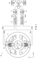
FIG. 1 , atorque sensor 10 comprises, for example, afirst structure 11,second structure 12, a plurality of third structures 13 serving as beam parts, first bridge circuit B1, and second bridge circuit B2. - The
first structure 11 andsecond structure 12 have, for example, annular shapes and, thesecond structure 12 andfirst structure 11 constitute concentric circles. A plurality ofthird structures first structure 11 andsecond structure 12 to each other. In the first embodiment, thethird structures - The
first structure 11 is attached to, for example, one of joints of a robot arm (not shown), the one of joints being an object to be measured. More specifically, thefirst structure 11 is attached to, for example, a speed reducer (not shown) and, the speed reducer is coupled to a motor (not shown). Thesecond structure 12 is attached to, for example, the other of the joints of the robot arm (not shown). - The
third structures first structure 11 and thesecond structure 12. - The
first structure 11,second structure 12, andthird structures first structure 11,second structure 12, andthird structures - Of the
third structures third structures - The first bridge circuit B1 is constituted of first to fourth strain sensors (strain gages) G1 to G4, and second bridge circuit B2 is constituted of fifth to eighth strain sensors G5 to G8.
- The first strain sensor G1 and second strain sensor G2 of the first bridge circuit B1, and fifth strain sensor G5 and sixth strain sensor G6 of the second bridge circuit B2 are provided on the
third structure 13a and, third strain sensor G3 and fourth strain sensor G4 of the first bridge circuit B1, and seventh strain sensor G7 and eighth strain sensor G8 of the second bridge circuit B2 are provided on thethird structure 13c. - Each of the first to eighth strain sensors G1 to G8 is constituted of a thin-film resistive element provided on a metallic plate (not shown) through an insulating film. However, the configuration of each of the first to eighth strain sensors G1 to G8 is not limited to this.
- The metallic plate of each of the first to eighth strain sensors G1 to G8 is fixed to the surface of the
third structure 13a orthird structure 13c by means of, for example, adhesive bonding, screwing, welding or the like. - Further, although the first strain sensor G1, second strain sensor G2, fifth strain sensor G5 and sixth strain sensor G6 are provided on the
third structure 13a, and third strain sensor G3, fourth strain sensor G4, seventh strain sensor G7, and eighth strain sensor G8 are provided on thethird structure 13c, the arrangement of the strain sensors is not limited to this. - For example, the metallic plate provided in each of the first to eighth strain sensors G1 to G8 may also be used as a strain body. In this case, the metallic plates of the first strain sensor G1, second strain sensor G2, fifth strain sensor G5, and sixth strain sensor G6 may be provided between the
first structure 11 andsecond structure 12 at positions other than thethird structures first structure 11 andsecond structure 12. The metallic plate of each strain sensor may be fixed to thefirst structure 11 orsecond structure 12 by means of, for example, adhesive bonding, screwing, welding or the like. - In the first bridge circuit B1, the first strain sensor G1 and third strain sensor G3 are connected in series, and second strain sensor G2 and fourth strain sensor G4 are also connected in series. The first strain sensor G1 and third strain sensor G3 connected in series are connected in parallel with the second strain sensor G2 and fourth strain sensor G4 connected in series
- A power-supply voltage Vo, for example, 5 V is supplied to a connection node between the second strain sensor G2 and fourth strain sensor G4, and connection node between the first strain sensor G1 and third strain sensor G3 is grounded.
- In the second bridge circuit B2, the fifth strain sensor G5 and seventh strain sensor G7 are connected in series, and sixth strain sensor G6 and eighth strain sensor G8 are also connected in series. The fifth strain sensor G5 and seventh strain sensor G7 connected in series are connected in parallel with the sixth strain sensor G6 and eighth strain sensor G8 connected in series.
- A power-supply voltage Vo, for example, 5 V is supplied to a connection node between the sixth strain sensor G6 and eighth strain sensor G8, and connection node between the fifth strain sensor G5 and seventh strain sensor G7 is grounded.
- In the first bridge circuit B1, a connection node between the first strain sensor G1 and second strain sensor G2 is connected to a first input terminal of a first
voltage detecting circuit 15, and connection node between the third strain sensor G3 and fourth strain sensor G4 is connected to a second input terminal of the firstvoltage detecting circuit 15. - In the second bridge circuit B2, a connection node between the fifth strain sensor G5 and sixth strain sensor G6 is connected to a first input terminal of a second
voltage detecting circuit 16, and connection node between the seventh strain sensor G7 and eighth strain sensor G8 is connected to a second input terminal of the secondvoltage detecting circuit 16. - The first
voltage detecting circuit 15 detects an output voltage of the first bridge circuit B1, and secondvoltage detecting circuit 16 detects an output voltage of the second bridge circuit B2. Each of the firstvoltage detecting circuit 15 and secondvoltage detecting circuit 16 is constituted of, for example, voltage-dividing resistors and operational amplifier. However, the configuration of each of the first and secondvoltage detecting circuits - The principle of operation of the first
voltage detecting circuit 15 is as follows. - For example, when torque (in the clockwise direction or counterclockwise direction of the
first structure 11 and second structure 12) is applied to thetorque sensor 10, in the first bridge circuit B1, an output voltage Vout+ is output from the connection point between the first strain sensor G1 and second strain sensor G2, and output voltage Vout- is output from the connection point between the third strain sensor G3 and fourth strain sensor G4. From the output voltage Vout+ and output voltage Vout-, an output voltage Vout1 of the first bridge circuit B1 indicated by a formula (1) is obtained.
- R1 is the resistance value of the first strain sensor G1,
- R2 is the resistance value of the second strain sensor G2,
- R3 is the resistance value of the third strain sensor G3,
- R4 is the resistance value of the fourth strain sensor G4, and
- R1=R2=R3=R4=R is obtained in a state where no torque is applied to the
torque sensor 10. - On the other hand, when force other than torque, for example, thrust force (force to be applied to the
first structure 11 andsecond structure 12 shown inFIG. 1 in the horizontal direction (X direction) or in the vertical direction (Y direction)) is applied to thetorque sensor 10, changes in the resistance values of the first strain sensor G1, second strain sensor G2, third strain sensor G3, and fourth strain sensor G4 (R1=R-ΔR, R2=R+ΔR, R3=R-ΔR, R4=R+ΔR, where ΔR is a value of a change in the resistance value) cancel each other, and the output voltage Vout1 of the first bridge circuit B1 becomes 0 V. - The principle of operation of the second
voltage detecting circuit 16 corresponding to the second bridge circuit B2 is identical to the firstvoltage detecting circuit 15. An output voltage Vout2 of the secondvoltage detecting circuit 16 is also obtained in the same manner as the firstvoltage detecting circuit 15. - The output voltage Vout1 of the first
voltage detecting circuit 15 is supplied to an analog-to-digital (A/D)converter circuit 17, and is converted into a digital signal and, output voltage Vout2 of the secondvoltage detecting circuit 16 is supplied to an A/D converter circuit 18, and is converted into a digital signal. Output signals of the A/D converter circuit 17 and A/D converter circuit 18 (hereinafter referred to also as output signals of the first bridge circuit B1 and second bridge circuit B2) are supplied to, for example, acontroller 19 periodically. Thecontroller 19 supplies one or both of the output signals of the A/D converter circuit 17 and A/D converter circuit 18 to an external device as an output signal or output signals of thetorque sensor 10 or detects an abnormality of thetorque sensor 10 to be described later. - Further, the
controller 19 is provided with astorage part 20 capable of storing therein the output signals of the A/D converter circuit 17 and A/D converter circuit 18 for, for example, a fixed period. The output signals of the A/D converter circuit 17 and A/D converter circuit 18 stored in thestorage part 20 are updated, for example, every fixed periods. - Furthermore, to the
controller 19, for example, adisplay device 21 is connected. Thedisplay device 21 displays a detection output signal of thetorque sensor 10 and signal or the like indicating that an abnormality of thetorque sensor 10 has been detected. -
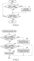
FIG. 2 and FIG. 3 are flowcharts for explaining the operation of thecontroller 19. - In normal times, in the
torque sensor 10, both the first bridge circuit B1 and second bridge circuit B2 simultaneously operate, and the output voltages of the first bridge circuit B1 and second bridge circuit B2 are compared with each other. That is, thecontroller 19 obtains an absolute value of a difference between the output voltage Vout1 of the first bridge circuit B1 supplied thereto from the firstvoltage detecting circuit 15 through the A/D converter circuit 17 and output voltage Vout2 of the second bridge circuit B2 supplied thereto from the secondvoltage detecting circuit 16 through the A/D converter circuit 18, and compares the absolute value of the difference with a first threshold voltage (S1). It should be noted that the absolute value is not indispensable, and it is sufficient if the difference between both the output voltages can be obtained. - When the absolute value of the difference is less than the first threshold voltage as a result of the above comparison (S1, NO), it is determined that both the first bridge circuit B1 and second bridge circuit B2 normally operate. The
controller 19 determines whether or not a predetermined operation of thetorque sensor 10 has been completed on the basis the output voltage of, for example, one of the first bridge circuit B1 and second bridge circuit B2 (S2). The predetermined operation implies, as described previously, an operation of, for example, supplying the output signal of thetorque sensor 10 to the external device, detecting an abnormality of thetorque sensor 10 or the like. When the predetermined operation has not been completed yet as a result of this determination (S2, NO), the control is moved to S1. Further, when the predetermined operation has already been completed (S2, YES), the control is terminated. - On the other hand, when it is determined in S1 that the absolute value of the difference is greater than the first threshold voltage (S1, YES), the control is moved to an abnormality processing routine S3. That is, that the absolute value of the difference is greater than the first threshold voltage implies that an abnormality has occurred in one of the first bridge circuit B1 and second bridge circuit B2. Accordingly, in the abnormality processing routine S3, it is determined in which of the first bridge circuit B1 and second bridge circuit B2 the abnormality has occurred.
-
FIG. 3 shows an example of the abnormality processing routine S3. - First, the
controller 19 obtains an absolute value of a difference between the output voltage Vout1 of the first bridge circuit B1 and last output voltage Vout11 of the first bridge circuit B1 stored in thestorage part 20, and determines whether or not this absolute value is greater than a second threshold voltage (S31). The second threshold voltage may be equal to the first threshold voltage or may be less than or equal to the first threshold voltage. - When the absolute value of the difference is greater than the second threshold voltage as a result of this determination (S31, YES), it is determined that the first bridge circuit B1 is abnormal, and power supply to, for example, the first bridge circuit B1 is stopped. Concomitantly with this, a signal indicating an abnormality is supplied to the
display device 21, and it is displayed on thedisplay device 21 that the first bridge circuit B1 is abnormal (S32). After this, the control is moved to, for example, S2, and the predetermined operation is executed by using the normal second bridge circuit B2. - On the other hand, when the absolute value is less than or equal to the second threshold voltage, it is determined that the first bridge circuit B1 is normal (S31, NO), the
controller 19 obtains an absolute value of a difference between the output voltage Vout2 of the second bridge circuit B2 and last output voltage Vout21 of the second bridge circuit B2 stored in thestorage part 20, and determines whether or not this absolute value of the difference is greater than the second threshold voltage (S33). - As a result of this determination, when the absolute value of the difference is greater than the second threshold voltage (S33, YES), it is determined that the second bridge circuit B2 is abnormal, and power supply to, for example, the second bridge circuit B2 is stopped. Concomitantly with this, a signal indicating an abnormality is supplied to the
display device 21, and it is displayed on thedisplay device 21 that the second bridge circuit B2 is abnormal (S34). After this, the control is moved to, for example, S2, and the predetermined operation is executed by using the normal first bridge circuit B1. - Further, when it is determined in S33 that the absolute value of the difference is less than or equal to the second threshold voltage (S33, NO), it is determined that an abnormality has not been detected in neither of the first bridge circuit B1 and second bridge circuit B2 in the determination of this time. When such a result is brought about, it is conceivable as a cause that an abnormality or the like may have occurred in something other than the
torque sensor 10. Accordingly, when it is determined in S33 that the absolute value is less than or equal to the second threshold voltage (S33, NO), it is displayed on thedisplay device 21, for example, that an abnormality has occurred (S35). After this, the control is moved to S2. - As described above, when an abnormality is detected in one of the first bridge circuit B1 and second bridge circuit B2 in the abnormality processing routine S3, one of the first bridge circuit B1 and second bridge circuit, the one being the bridge circuit in which the abnormality is detected is stopped, and the operation of the
torque sensor 10 is continued by using the other of the first bridge circuit B1 and second bridge circuit B2, the other being the normal bridge circuit. - However, the abnormality processing routine is not limited to this and, when an abnormality is detected in S1, both the first bridge circuit B1 and second bridge circuit B2 may immediately be stopped, and it may be displayed on the
display device 21 that an abnormality has occurred in thetorque sensor 10. - According to the first embodiment described above, the
torque sensor 10 is provided with the first bridge circuit B1 and second bridge circuit B2 and, when the difference (absolute value thereof) between the output voltage of the first bridge circuit B1 and output voltage of the second bridge circuit B2 is greater than the first threshold voltage, it is determined that an abnormality has occurred in one of the first bridge circuit B1 and second bridge circuit B2. Accordingly, it is possible to detect an abnormality of thetorque sensor 10 before both the first bridge circuit B1 and second bridge circuit B2 go out of order. Therefore, thetorque sensor 10 has a fail-safe function, and it is possible to prevent beforehand a robot arm equipped with thetorque sensor 10 from causing a collision or the like. - Further, when an abnormality has occurred in the first bridge circuit B1 or in the second bridge circuit B2, it is possible to identify and stop the bridge circuit in which the abnormality has occurred, and continue the operation by using the normal bridge circuit. Accordingly, it is possible to make the
torque sensor 10 continue to operate by using the normal bridge circuit, and carry out control or the like to stop the robot arm after moving the robot arm to, for example, a safe position. - In the first embodiment, both the first bridge circuit B1 and second bridge circuit B2 are provided on the
first structures - Conversely, in a second embodiment, a first bridge circuit B1 and second bridge circuit B2 are arranged in such a manner that the first bridge circuit B1 and second bridge circuit B2 intersect each other.
-
FIG. 4 shows an example of the second embodiment. - As shown in
FIG. 4 , a first strain sensor G1 and second strain sensor G2 of the first bridge circuit B1 are arranged on athird structure 13a, and third strain sensor G3 and fourth strain sensor G4 of the first bridge circuit B1 are arranged on athird structure 13c. - Further, a fifth strain sensor G5 and sixth strain sensor G6 of the second bridge circuit B2 are arranged on a
third structure 13b, and seventh strain sensor G7 and eighth strain sensor G8 of the second bridge circuit B2 are arranged on athird structure 13d. - In the second embodiment, the circuit configuration and operation are the same as the first embodiment.
- It is possible to obtain, by the second embodiment too, an advantage identical to the first embodiment.
- Moreover, according to the second embodiment, the first bridge circuit B1 and second bridge circuit B2 are arranged in such a manner that the first bridge circuit B1 and second bridge circuit B2 intersect each other, the first to fourth strain sensors G1 to G4 of the first bridge circuit B1 are arranged on the
third structures third structures third structures - In the first and second embodiments, the abnormality of the first bridge circuit B1 or second bridge circuit B2 is detected on the basis of a digital signal. However, detection of the abnormality is not limited to this, and it is also possible to detect an abnormality of the first bridge circuit B1 or second bridge circuit B2 on the basis of an analog signal.
-
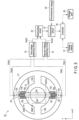
FIG. 5 shows an example of a third embodiment. - In the third embodiment, although the arrangement of the first bridge circuit B1 and second bridge circuit B2 is done in the same manner as the first embodiment, i.e., the first bridge circuit B1 and second bridge circuit B2 are arranged in parallel with each other, the first bridge circuit B1 and second bridge circuit B2 may be arranged in the same manner as the second embodiment, i.e., the first bridge circuit B1 and second bridge circuit B2 may be arranged in such a manner that the first bridge circuit B1 and second bridge circuit B2 intersect each other.
- Output voltages Vout+ and Vout- of the first bridge circuit B1 are supplied to a first
voltage detecting circuit 15, and output voltages Vout+ and Vout- of the second bridge circuit B2 are supplied to a secondvoltage detecting circuit 16. An output voltage Vout1 of the firstvoltage detecting circuit 15 and output voltage Vout2 of the secondvoltage detecting circuit 16 are supplied to a subtractingcircuit 22. The subtractingcircuit 22 outputs a voltage of a difference between the output voltage Vout1 of the firstvoltage detecting circuit 15 and output voltage Vout2 of the secondvoltage detecting circuit 16. An output voltage of the subtractingcircuit 22 andfirst threshold voltage 24 are supplied to a comparison circuit 23. The comparison circuit 23 compares the output voltage of the subtractingcircuit 22 andfirst threshold voltage 24 with each other. A comparison result of the comparison circuit 23 is supplied to acontroller 19. When the comparison result of the comparison circuit 23 indicates an abnormality, thecontroller 19 stops power supply to, for example, the first bridge circuit B1 and second bridge circuit B2, and stops, for example, the operation of the robot arm. Alternatively, as in the case of the first embodiment, thecontroller 19 may also be configured to detect one of the first bridge circuit B1 and second bridge circuit B2, the one being the bridge circuit having an abnormality. - It is possible to obtain, by the third embodiment too, an advantage identical to the second embodiment. Moreover, by carrying out processing on the basis of an analog signal, it is possible to enhance the processing speed.
- In addition, the present invention is not limited to the above embodiments as it is, and at the implementation stage, the constituent elements can be modified and embodied without departing from the scope of the invention. In addition, various inventions can be formed by appropriate combinations of a plurality of constituent elements disclosed in the above embodiments. For example, some components may be deleted from all the components shown in the embodiment. Furthermore, components in different embodiments may be combined as appropriate. However the present invention is defined by the scope of the appended claims.
- The present invention can be applied to, for example, a torque sensor provided at a joint of a robot arm.
- 10 ... torque sensor, 11 ... first structure, 12 ... second structure, 13a, 13b, 13c, 13d ... third structure, B1 ... first bridge circuit, B2 ... second bridge circuit, G1 to G8 ... first strain sensor to eighth strain sensor, 15 ... first voltage detecting circuit, 16 ... second voltage detecting circuit, 19 ... controller, 20 ... storage part, 21 ... display device.
Claims (3)
- A torque sensor (10) comprising:a first structure (11) to be coupled to an object to be measured;a second structure (12);a plurality of third structures (13a, 13b, 13c, and 13d) coupling the first structure (11) and second structure (12) to each other;a first bridge circuit (B1) including a plurality of first strain sensors (G1-G4) configured to detect force to be transmitted between the first structure (11) and the second structure (12);a second bridge circuit (B2) including a plurality of second strain sensors (G5-G8) configured to detect force to be transmitted between the first structure (11) and the second structure (12);a first detecting circuit (15) configured to detect a first output voltage of the first bridge circuit (B1);a second detecting circuit (16) configured to detect a second output voltage of the second bridge circuit (B2);a memory (20) configured to store the first output voltage from the first detecting circuit and the second output voltage from the second detecting circuit; anda controller (19) configured to output a signal indicating an abnormality when a difference between the first output voltage of the first bridge circuit (B1) and the second output voltage of the second bridge circuit (B2) is greater than a first threshold voltage;characterized in thateach of the strain sensors (G1-G8) is constituted of a thin-film resistive element provided on a metallic plate through an insulating film, and the metallic plate of each of the strain sensors (G1-G8) is fixed to the surface of the third structure (13a or 13c) by means of screwing, and in thatthe controller (19) is configured to stopthe first bridge circuit (B1) when a difference between the first output voltage supplied from the first detecting circuit (15) and the first output voltage stored in the memory (20) is greater than a second threshold voltage, and to stop the second bridge circuit (B2) when a difference between the second output voltage supplied from the second detecting circuit (16) and the second output voltage stored in the memory (20) is greater than the second threshold voltage.
- The torque sensor of Claim 1 characterized in that
the first strain sensors (G1-G4) included in the first bridge circuit (B1) and the second strain sensors (G5-G8) included in the second bridge circuit (B2) are arranged in parallel with each other. - The torque sensor of Claim 1 characterized in that
the first strain sensors (G1-G4) included in the first bridge circuit (B1) and the second strain sensors (G5-G8) included in the second bridge circuit (B2) are arranged in directions perpendicular to each other.
Applications Claiming Priority (2)
| Application Number | Priority Date | Filing Date | Title |
|---|---|---|---|
| JP2017023885A JP6692762B2 (en) | 2017-02-13 | 2017-02-13 | Torque sensor |
| PCT/JP2017/042906 WO2018146917A1 (en) | 2017-02-13 | 2017-11-29 | Torque sensor |
Publications (3)
| Publication Number | Publication Date |
|---|---|
| EP3581908A1 EP3581908A1 (en) | 2019-12-18 |
| EP3581908A4 EP3581908A4 (en) | 2020-12-30 |
| EP3581908B1 true EP3581908B1 (en) | 2023-06-28 |
Family
ID=63108002
Family Applications (1)
| Application Number | Title | Priority Date | Filing Date |
|---|---|---|---|
| EP17895539.9A Active EP3581908B1 (en) | 2017-02-13 | 2017-11-29 | Torque sensor |
Country Status (5)
| Country | Link |
|---|---|
| US (1) | US10955309B2 (en) |
| EP (1) | EP3581908B1 (en) |
| JP (1) | JP6692762B2 (en) |
| CN (1) | CN110121638A (en) |
| WO (1) | WO2018146917A1 (en) |
Families Citing this family (10)
| Publication number | Priority date | Publication date | Assignee | Title |
|---|---|---|---|---|
| JP6976892B2 (en) * | 2018-03-29 | 2021-12-08 | 日本電産コパル電子株式会社 | Torque sensor |
| JP2020012660A (en) * | 2018-07-13 | 2020-01-23 | 日本電産コパル電子株式会社 | Torque sensor |
| JP6964212B2 (en) * | 2019-07-24 | 2021-11-10 | Semitec株式会社 | A device equipped with a contact force sensor and a contact force sensor |
| DE102020101424B3 (en) * | 2020-01-22 | 2021-04-15 | Schaeffler Technologies AG & Co. KG | Method for checking an arrangement of at least three strain gauges and stress wave gears |
| EP3896416B1 (en) * | 2020-04-16 | 2025-08-13 | TE Connectivity Sensors France | Torque sensor device |
| CN111347446A (en) * | 2020-04-17 | 2020-06-30 | 成都卡诺普自动化控制技术有限公司 | Hollow type cooperative robot mechanical arm joint |
| CN111579133B (en) * | 2020-05-27 | 2021-10-01 | 安徽大学 | A variable-configuration force sensor with continuously adjustable force resolution |
| CN112665765A (en) * | 2020-12-01 | 2021-04-16 | 哈尔滨工业大学 | Robot high-rigidity joint torque sensor based on parallel load sharing principle |
| TWI805978B (en) * | 2020-12-22 | 2023-06-21 | 達明機器人股份有限公司 | Two loops torque sensing system and sensing method thereof |
| CN115790926B (en) * | 2022-12-01 | 2023-07-04 | 华中科技大学 | Torque measuring method and device for motor unit |
Citations (3)
| Publication number | Priority date | Publication date | Assignee | Title |
|---|---|---|---|---|
| US20070240519A1 (en) * | 2006-03-22 | 2007-10-18 | Hitachi, Ltd. | Mechanical quantity measuring apparatus |
| EP2184576A1 (en) * | 2007-08-27 | 2010-05-12 | Hitachi Ltd. | Semiconductor strain sensor |
| EP2322905A1 (en) * | 2009-11-16 | 2011-05-18 | Baumer Innotec AG | Force measurement cell for measuring the injection force of injection moulding |
Family Cites Families (17)
| Publication number | Priority date | Publication date | Assignee | Title |
|---|---|---|---|---|
| JPS5640905B2 (en) | 1973-10-31 | 1981-09-24 | ||
| US3915015A (en) * | 1974-03-18 | 1975-10-28 | Stanford Research Inst | Strain gauge transducer system |
| JPS5947494B2 (en) | 1977-01-28 | 1984-11-19 | 株式会社日立製作所 | surface acoustic wave filter |
| JP3444952B2 (en) * | 1994-02-28 | 2003-09-08 | 大和製衡株式会社 | Load cell failure detection device and failure recovery device |
| JP4026247B2 (en) * | 1998-10-01 | 2007-12-26 | 日本精工株式会社 | Torque sensor |
| US20080204266A1 (en) * | 2004-02-03 | 2008-08-28 | Jussi Malmberg | Method and Device For Implementing Vibration Output Commands in Mobile Terminal Devices |
| JP4764619B2 (en) * | 2004-08-23 | 2011-09-07 | 株式会社エー・アンド・デイ | Rotary component force measuring device |
| CN101365609A (en) * | 2005-12-13 | 2009-02-11 | Tk电子控股公司 | Signal processing system and method |
| EP2510325A2 (en) * | 2009-12-08 | 2012-10-17 | Abb Ag | Multiaxial force-torque sensors |
| JP5640905B2 (en) * | 2011-06-14 | 2014-12-17 | トヨタ自動車株式会社 | Straining body and apparatus including the same |
| JP5947494B2 (en) * | 2011-06-30 | 2016-07-06 | トヨタ自動車株式会社 | Method for manufacturing torque measuring device |
| US8966996B2 (en) * | 2011-07-27 | 2015-03-03 | Tri-Force Management Corporation | Force sensor |
| JP5699904B2 (en) * | 2011-10-28 | 2015-04-15 | トヨタ自動車株式会社 | Straining body and torque sensor |
| CN203164326U (en) * | 2013-03-11 | 2013-08-28 | 唐山钢铁集团微尔自动化有限公司 | Digital display type detection device of resistor strain sensor |
| JP6135408B2 (en) * | 2013-09-04 | 2017-05-31 | トヨタ自動車株式会社 | Torque sensor, driving device, and robot |
| US10422707B2 (en) * | 2016-01-19 | 2019-09-24 | Ati Industrial Automation, Inc. | Compact robotic force/torque sensor including strain gages |
| JP6214072B1 (en) * | 2016-08-09 | 2017-10-18 | 株式会社トライフォース・マネジメント | Force sensor |
-
2017
- 2017-02-13 JP JP2017023885A patent/JP6692762B2/en active Active
- 2017-11-29 EP EP17895539.9A patent/EP3581908B1/en active Active
- 2017-11-29 CN CN201780080958.8A patent/CN110121638A/en active Pending
- 2017-11-29 WO PCT/JP2017/042906 patent/WO2018146917A1/en not_active Ceased
-
2019
- 2019-06-25 US US16/451,839 patent/US10955309B2/en not_active Expired - Fee Related
Patent Citations (3)
| Publication number | Priority date | Publication date | Assignee | Title |
|---|---|---|---|---|
| US20070240519A1 (en) * | 2006-03-22 | 2007-10-18 | Hitachi, Ltd. | Mechanical quantity measuring apparatus |
| EP2184576A1 (en) * | 2007-08-27 | 2010-05-12 | Hitachi Ltd. | Semiconductor strain sensor |
| EP2322905A1 (en) * | 2009-11-16 | 2011-05-18 | Baumer Innotec AG | Force measurement cell for measuring the injection force of injection moulding |
Also Published As
| Publication number | Publication date |
|---|---|
| EP3581908A1 (en) | 2019-12-18 |
| JP2018132313A (en) | 2018-08-23 |
| US10955309B2 (en) | 2021-03-23 |
| EP3581908A4 (en) | 2020-12-30 |
| CN110121638A (en) | 2019-08-13 |
| US20190346329A1 (en) | 2019-11-14 |
| WO2018146917A1 (en) | 2018-08-16 |
| JP6692762B2 (en) | 2020-05-13 |
Similar Documents
| Publication | Publication Date | Title |
|---|---|---|
| EP3581908B1 (en) | Torque sensor | |
| JP5333619B2 (en) | Voltage detection device and coupling circuit | |
| JP6515989B2 (en) | Electric power steering device | |
| JP6512268B2 (en) | Steering angle detection device for vehicle and electric power steering device equipped with the same | |
| US20210199539A1 (en) | Test device | |
| EP3232209B1 (en) | Insulation resistance measuring device and method | |
| US9327408B2 (en) | Robot control device detecting contact with external environment | |
| JP4908608B2 (en) | Electric load current control device | |
| CN111070237B (en) | Integrated joint and integrated joint multi-sensor control system and method | |
| US11499879B2 (en) | Torque sensor having a strain sensor | |
| CN111684250B (en) | torque sensor | |
| JP6549812B2 (en) | Torque sensor and robot | |
| WO2018207319A1 (en) | Electronic control device | |
| JP2017083303A (en) | Semiconductor device and cell voltage measuring method | |
| US10724912B2 (en) | Sensor device | |
| JP5846092B2 (en) | Voltage detector | |
| EP3130894B1 (en) | Abnormality detection device for sensor and sensor device | |
| KR102612239B1 (en) | Motor Controlling Apparatus And The Method Thereof | |
| US8939024B2 (en) | Angular velocity sensor | |
| TW201942550A (en) | Torque sensor | |
| JP5016538B2 (en) | A / D conversion apparatus and method | |
| JP4064303B2 (en) | Sense comparator circuit and offset compensation method thereof | |
| JP6879189B2 (en) | A / D converter | |
| JP2008058168A (en) | Detecting device for force sensor |
Legal Events
| Date | Code | Title | Description |
|---|---|---|---|
| STAA | Information on the status of an ep patent application or granted ep patent |
Free format text: STATUS: THE INTERNATIONAL PUBLICATION HAS BEEN MADE |
|
| PUAI | Public reference made under article 153(3) epc to a published international application that has entered the european phase |
Free format text: ORIGINAL CODE: 0009012 |
|
| STAA | Information on the status of an ep patent application or granted ep patent |
Free format text: STATUS: REQUEST FOR EXAMINATION WAS MADE |
|
| 17P | Request for examination filed |
Effective date: 20190625 |
|
| AK | Designated contracting states |
Kind code of ref document: A1 Designated state(s): AL AT BE BG CH CY CZ DE DK EE ES FI FR GB GR HR HU IE IS IT LI LT LU LV MC MK MT NL NO PL PT RO RS SE SI SK SM TR |
|
| AX | Request for extension of the european patent |
Extension state: BA ME |
|
| DAV | Request for validation of the european patent (deleted) | ||
| DAX | Request for extension of the european patent (deleted) | ||
| A4 | Supplementary search report drawn up and despatched |
Effective date: 20201126 |
|
| RIC1 | Information provided on ipc code assigned before grant |
Ipc: G01L 3/10 20060101ALI20201120BHEP Ipc: G01L 25/00 20060101AFI20201120BHEP Ipc: G01L 5/00 20060101ALI20201120BHEP |
|
| STAA | Information on the status of an ep patent application or granted ep patent |
Free format text: STATUS: EXAMINATION IS IN PROGRESS |
|
| 17Q | First examination report despatched |
Effective date: 20220715 |
|
| GRAP | Despatch of communication of intention to grant a patent |
Free format text: ORIGINAL CODE: EPIDOSNIGR1 |
|
| STAA | Information on the status of an ep patent application or granted ep patent |
Free format text: STATUS: GRANT OF PATENT IS INTENDED |
|
| INTG | Intention to grant announced |
Effective date: 20230120 |
|
| GRAS | Grant fee paid |
Free format text: ORIGINAL CODE: EPIDOSNIGR3 |
|
| GRAA | (expected) grant |
Free format text: ORIGINAL CODE: 0009210 |
|
| STAA | Information on the status of an ep patent application or granted ep patent |
Free format text: STATUS: THE PATENT HAS BEEN GRANTED |
|
| AK | Designated contracting states |
Kind code of ref document: B1 Designated state(s): AL AT BE BG CH CY CZ DE DK EE ES FI FR GB GR HR HU IE IS IT LI LT LU LV MC MK MT NL NO PL PT RO RS SE SI SK SM TR |
|
| REG | Reference to a national code |
Ref country code: CH Ref legal event code: EP |
|
| REG | Reference to a national code |
Ref country code: AT Ref legal event code: REF Ref document number: 1583101 Country of ref document: AT Kind code of ref document: T Effective date: 20230715 |
|
| REG | Reference to a national code |
Ref country code: IE Ref legal event code: FG4D |
|
| REG | Reference to a national code |
Ref country code: DE Ref legal event code: R096 Ref document number: 602017070820 Country of ref document: DE |
|
| REG | Reference to a national code |
Ref country code: LT Ref legal event code: MG9D |
|
| PG25 | Lapsed in a contracting state [announced via postgrant information from national office to epo] |
Ref country code: SE Free format text: LAPSE BECAUSE OF FAILURE TO SUBMIT A TRANSLATION OF THE DESCRIPTION OR TO PAY THE FEE WITHIN THE PRESCRIBED TIME-LIMIT Effective date: 20230628 Ref country code: NO Free format text: LAPSE BECAUSE OF FAILURE TO SUBMIT A TRANSLATION OF THE DESCRIPTION OR TO PAY THE FEE WITHIN THE PRESCRIBED TIME-LIMIT Effective date: 20230928 |
|
| REG | Reference to a national code |
Ref country code: NL Ref legal event code: MP Effective date: 20230628 |
|
| REG | Reference to a national code |
Ref country code: AT Ref legal event code: MK05 Ref document number: 1583101 Country of ref document: AT Kind code of ref document: T Effective date: 20230628 |
|
| PG25 | Lapsed in a contracting state [announced via postgrant information from national office to epo] |
Ref country code: RS Free format text: LAPSE BECAUSE OF FAILURE TO SUBMIT A TRANSLATION OF THE DESCRIPTION OR TO PAY THE FEE WITHIN THE PRESCRIBED TIME-LIMIT Effective date: 20230628 Ref country code: NL Free format text: LAPSE BECAUSE OF FAILURE TO SUBMIT A TRANSLATION OF THE DESCRIPTION OR TO PAY THE FEE WITHIN THE PRESCRIBED TIME-LIMIT Effective date: 20230628 Ref country code: LV Free format text: LAPSE BECAUSE OF FAILURE TO SUBMIT A TRANSLATION OF THE DESCRIPTION OR TO PAY THE FEE WITHIN THE PRESCRIBED TIME-LIMIT Effective date: 20230628 Ref country code: LT Free format text: LAPSE BECAUSE OF FAILURE TO SUBMIT A TRANSLATION OF THE DESCRIPTION OR TO PAY THE FEE WITHIN THE PRESCRIBED TIME-LIMIT Effective date: 20230628 Ref country code: HR Free format text: LAPSE BECAUSE OF FAILURE TO SUBMIT A TRANSLATION OF THE DESCRIPTION OR TO PAY THE FEE WITHIN THE PRESCRIBED TIME-LIMIT Effective date: 20230628 Ref country code: GR Free format text: LAPSE BECAUSE OF FAILURE TO SUBMIT A TRANSLATION OF THE DESCRIPTION OR TO PAY THE FEE WITHIN THE PRESCRIBED TIME-LIMIT Effective date: 20230929 |
|
| PG25 | Lapsed in a contracting state [announced via postgrant information from national office to epo] |
Ref country code: FI Free format text: LAPSE BECAUSE OF FAILURE TO SUBMIT A TRANSLATION OF THE DESCRIPTION OR TO PAY THE FEE WITHIN THE PRESCRIBED TIME-LIMIT Effective date: 20230628 |
|
| PG25 | Lapsed in a contracting state [announced via postgrant information from national office to epo] |
Ref country code: SK Free format text: LAPSE BECAUSE OF FAILURE TO SUBMIT A TRANSLATION OF THE DESCRIPTION OR TO PAY THE FEE WITHIN THE PRESCRIBED TIME-LIMIT Effective date: 20230628 |
|
| PG25 | Lapsed in a contracting state [announced via postgrant information from national office to epo] |
Ref country code: ES Free format text: LAPSE BECAUSE OF FAILURE TO SUBMIT A TRANSLATION OF THE DESCRIPTION OR TO PAY THE FEE WITHIN THE PRESCRIBED TIME-LIMIT Effective date: 20230628 |
|
| PG25 | Lapsed in a contracting state [announced via postgrant information from national office to epo] |
Ref country code: IS Free format text: LAPSE BECAUSE OF FAILURE TO SUBMIT A TRANSLATION OF THE DESCRIPTION OR TO PAY THE FEE WITHIN THE PRESCRIBED TIME-LIMIT Effective date: 20231028 |
|
| PG25 | Lapsed in a contracting state [announced via postgrant information from national office to epo] |
Ref country code: SM Free format text: LAPSE BECAUSE OF FAILURE TO SUBMIT A TRANSLATION OF THE DESCRIPTION OR TO PAY THE FEE WITHIN THE PRESCRIBED TIME-LIMIT Effective date: 20230628 Ref country code: SK Free format text: LAPSE BECAUSE OF FAILURE TO SUBMIT A TRANSLATION OF THE DESCRIPTION OR TO PAY THE FEE WITHIN THE PRESCRIBED TIME-LIMIT Effective date: 20230628 Ref country code: RO Free format text: LAPSE BECAUSE OF FAILURE TO SUBMIT A TRANSLATION OF THE DESCRIPTION OR TO PAY THE FEE WITHIN THE PRESCRIBED TIME-LIMIT Effective date: 20230628 Ref country code: PT Free format text: LAPSE BECAUSE OF FAILURE TO SUBMIT A TRANSLATION OF THE DESCRIPTION OR TO PAY THE FEE WITHIN THE PRESCRIBED TIME-LIMIT Effective date: 20231030 Ref country code: IS Free format text: LAPSE BECAUSE OF FAILURE TO SUBMIT A TRANSLATION OF THE DESCRIPTION OR TO PAY THE FEE WITHIN THE PRESCRIBED TIME-LIMIT Effective date: 20231028 Ref country code: ES Free format text: LAPSE BECAUSE OF FAILURE TO SUBMIT A TRANSLATION OF THE DESCRIPTION OR TO PAY THE FEE WITHIN THE PRESCRIBED TIME-LIMIT Effective date: 20230628 Ref country code: EE Free format text: LAPSE BECAUSE OF FAILURE TO SUBMIT A TRANSLATION OF THE DESCRIPTION OR TO PAY THE FEE WITHIN THE PRESCRIBED TIME-LIMIT Effective date: 20230628 Ref country code: CZ Free format text: LAPSE BECAUSE OF FAILURE TO SUBMIT A TRANSLATION OF THE DESCRIPTION OR TO PAY THE FEE WITHIN THE PRESCRIBED TIME-LIMIT Effective date: 20230628 Ref country code: AT Free format text: LAPSE BECAUSE OF FAILURE TO SUBMIT A TRANSLATION OF THE DESCRIPTION OR TO PAY THE FEE WITHIN THE PRESCRIBED TIME-LIMIT Effective date: 20230628 |
|
| PG25 | Lapsed in a contracting state [announced via postgrant information from national office to epo] |
Ref country code: PL Free format text: LAPSE BECAUSE OF FAILURE TO SUBMIT A TRANSLATION OF THE DESCRIPTION OR TO PAY THE FEE WITHIN THE PRESCRIBED TIME-LIMIT Effective date: 20230628 |
|
| REG | Reference to a national code |
Ref country code: DE Ref legal event code: R097 Ref document number: 602017070820 Country of ref document: DE |
|
| PG25 | Lapsed in a contracting state [announced via postgrant information from national office to epo] |
Ref country code: DK Free format text: LAPSE BECAUSE OF FAILURE TO SUBMIT A TRANSLATION OF THE DESCRIPTION OR TO PAY THE FEE WITHIN THE PRESCRIBED TIME-LIMIT Effective date: 20230628 |
|
| PLBE | No opposition filed within time limit |
Free format text: ORIGINAL CODE: 0009261 |
|
| STAA | Information on the status of an ep patent application or granted ep patent |
Free format text: STATUS: NO OPPOSITION FILED WITHIN TIME LIMIT |
|
| PG25 | Lapsed in a contracting state [announced via postgrant information from national office to epo] |
Ref country code: IT Free format text: LAPSE BECAUSE OF FAILURE TO SUBMIT A TRANSLATION OF THE DESCRIPTION OR TO PAY THE FEE WITHIN THE PRESCRIBED TIME-LIMIT Effective date: 20230628 |
|
| 26N | No opposition filed |
Effective date: 20240402 |
|
| REG | Reference to a national code |
Ref country code: CH Ref legal event code: PL |
|
| PG25 | Lapsed in a contracting state [announced via postgrant information from national office to epo] |
Ref country code: MC Free format text: LAPSE BECAUSE OF FAILURE TO SUBMIT A TRANSLATION OF THE DESCRIPTION OR TO PAY THE FEE WITHIN THE PRESCRIBED TIME-LIMIT Effective date: 20230628 |
|
| PG25 | Lapsed in a contracting state [announced via postgrant information from national office to epo] |
Ref country code: LU Free format text: LAPSE BECAUSE OF NON-PAYMENT OF DUE FEES Effective date: 20231129 |
|
| PG25 | Lapsed in a contracting state [announced via postgrant information from national office to epo] |
Ref country code: CH Free format text: LAPSE BECAUSE OF NON-PAYMENT OF DUE FEES Effective date: 20231130 |
|
| GBPC | Gb: european patent ceased through non-payment of renewal fee |
Effective date: 20231129 |
|
| PG25 | Lapsed in a contracting state [announced via postgrant information from national office to epo] |
Ref country code: MC Free format text: LAPSE BECAUSE OF FAILURE TO SUBMIT A TRANSLATION OF THE DESCRIPTION OR TO PAY THE FEE WITHIN THE PRESCRIBED TIME-LIMIT Effective date: 20230628 Ref country code: LU Free format text: LAPSE BECAUSE OF NON-PAYMENT OF DUE FEES Effective date: 20231129 Ref country code: CH Free format text: LAPSE BECAUSE OF NON-PAYMENT OF DUE FEES Effective date: 20231130 Ref country code: SI Free format text: LAPSE BECAUSE OF FAILURE TO SUBMIT A TRANSLATION OF THE DESCRIPTION OR TO PAY THE FEE WITHIN THE PRESCRIBED TIME-LIMIT Effective date: 20230628 |
|
| REG | Reference to a national code |
Ref country code: BE Ref legal event code: MM Effective date: 20231130 |
|
| REG | Reference to a national code |
Ref country code: IE Ref legal event code: MM4A |
|
| PG25 | Lapsed in a contracting state [announced via postgrant information from national office to epo] |
Ref country code: IE Free format text: LAPSE BECAUSE OF NON-PAYMENT OF DUE FEES Effective date: 20231129 |
|
| PG25 | Lapsed in a contracting state [announced via postgrant information from national office to epo] |
Ref country code: GB Free format text: LAPSE BECAUSE OF NON-PAYMENT OF DUE FEES Effective date: 20231129 |
|
| PG25 | Lapsed in a contracting state [announced via postgrant information from national office to epo] |
Ref country code: BE Free format text: LAPSE BECAUSE OF NON-PAYMENT OF DUE FEES Effective date: 20231130 |
|
| PG25 | Lapsed in a contracting state [announced via postgrant information from national office to epo] |
Ref country code: FR Free format text: LAPSE BECAUSE OF NON-PAYMENT OF DUE FEES Effective date: 20231130 |
|
| PG25 | Lapsed in a contracting state [announced via postgrant information from national office to epo] |
Ref country code: IE Free format text: LAPSE BECAUSE OF NON-PAYMENT OF DUE FEES Effective date: 20231129 Ref country code: GB Free format text: LAPSE BECAUSE OF NON-PAYMENT OF DUE FEES Effective date: 20231129 Ref country code: FR Free format text: LAPSE BECAUSE OF NON-PAYMENT OF DUE FEES Effective date: 20231130 Ref country code: BE Free format text: LAPSE BECAUSE OF NON-PAYMENT OF DUE FEES Effective date: 20231130 |
|
| PG25 | Lapsed in a contracting state [announced via postgrant information from national office to epo] |
Ref country code: BG Free format text: LAPSE BECAUSE OF FAILURE TO SUBMIT A TRANSLATION OF THE DESCRIPTION OR TO PAY THE FEE WITHIN THE PRESCRIBED TIME-LIMIT Effective date: 20230628 |
|
| PG25 | Lapsed in a contracting state [announced via postgrant information from national office to epo] |
Ref country code: BG Free format text: LAPSE BECAUSE OF FAILURE TO SUBMIT A TRANSLATION OF THE DESCRIPTION OR TO PAY THE FEE WITHIN THE PRESCRIBED TIME-LIMIT Effective date: 20230628 |
|
| PG25 | Lapsed in a contracting state [announced via postgrant information from national office to epo] |
Ref country code: CY Free format text: LAPSE BECAUSE OF FAILURE TO SUBMIT A TRANSLATION OF THE DESCRIPTION OR TO PAY THE FEE WITHIN THE PRESCRIBED TIME-LIMIT; INVALID AB INITIO Effective date: 20171129 |
|
| PG25 | Lapsed in a contracting state [announced via postgrant information from national office to epo] |
Ref country code: HU Free format text: LAPSE BECAUSE OF FAILURE TO SUBMIT A TRANSLATION OF THE DESCRIPTION OR TO PAY THE FEE WITHIN THE PRESCRIBED TIME-LIMIT; INVALID AB INITIO Effective date: 20171129 |
|
| PG25 | Lapsed in a contracting state [announced via postgrant information from national office to epo] |
Ref country code: TR Free format text: LAPSE BECAUSE OF FAILURE TO SUBMIT A TRANSLATION OF THE DESCRIPTION OR TO PAY THE FEE WITHIN THE PRESCRIBED TIME-LIMIT Effective date: 20230628 |
|
| PGFP | Annual fee paid to national office [announced via postgrant information from national office to epo] |
Ref country code: DE Payment date: 20250930 Year of fee payment: 9 |